EP3952063A1 - Stator core - Google Patents
Stator core Download PDFInfo
- Publication number
- EP3952063A1 EP3952063A1 EP20778532.0A EP20778532A EP3952063A1 EP 3952063 A1 EP3952063 A1 EP 3952063A1 EP 20778532 A EP20778532 A EP 20778532A EP 3952063 A1 EP3952063 A1 EP 3952063A1
- Authority
- EP
- European Patent Office
- Prior art keywords
- core
- back portion
- core back
- protrusion
- recess
- Prior art date
- Legal status (The legal status is an assumption and is not a legal conclusion. Google has not performed a legal analysis and makes no representation as to the accuracy of the status listed.)
- Withdrawn
Links
Images




Classifications
-
- H—ELECTRICITY
- H02—GENERATION; CONVERSION OR DISTRIBUTION OF ELECTRIC POWER
- H02K—DYNAMO-ELECTRIC MACHINES
- H02K1/00—Details of the magnetic circuit
- H02K1/06—Details of the magnetic circuit characterised by the shape, form or construction
- H02K1/12—Stationary parts of the magnetic circuit
- H02K1/14—Stator cores with salient poles
- H02K1/146—Stator cores with salient poles consisting of a generally annular yoke with salient poles
-
- H—ELECTRICITY
- H02—GENERATION; CONVERSION OR DISTRIBUTION OF ELECTRIC POWER
- H02K—DYNAMO-ELECTRIC MACHINES
- H02K1/00—Details of the magnetic circuit
- H02K1/06—Details of the magnetic circuit characterised by the shape, form or construction
- H02K1/12—Stationary parts of the magnetic circuit
- H02K1/14—Stator cores with salient poles
- H02K1/146—Stator cores with salient poles consisting of a generally annular yoke with salient poles
- H02K1/148—Sectional cores
-
- H—ELECTRICITY
- H02—GENERATION; CONVERSION OR DISTRIBUTION OF ELECTRIC POWER
- H02K—DYNAMO-ELECTRIC MACHINES
- H02K15/00—Processes or apparatus specially adapted for manufacturing, assembling, maintaining or repairing of dynamo-electric machines
- H02K15/02—Processes or apparatus specially adapted for manufacturing, assembling, maintaining or repairing of dynamo-electric machines of stator or rotor bodies
- H02K15/021—Magnetic cores
- H02K15/022—Magnetic cores with salient poles
-
- H—ELECTRICITY
- H02—GENERATION; CONVERSION OR DISTRIBUTION OF ELECTRIC POWER
- H02K—DYNAMO-ELECTRIC MACHINES
- H02K2213/00—Specific aspects, not otherwise provided for and not covered by codes H02K2201/00 - H02K2211/00
- H02K2213/03—Machines characterised by numerical values, ranges, mathematical expressions or similar information
Definitions
- the present invention relates to a stator core.
- stator core of a motor As a stator core of a motor, a stator core in which a plurality of stator core plates punched into the shape of the stator core by a press device or the like are laminated in the thickness direction is known.
- the stator core includes a plurality of teeth provided radially, and a core back annularly connecting the teeth on a radially outer side of the teeth.
- a stator core in which a plurality of core pieces having teeth and segment core backs are annularly arranged is known.
- a stator core for example, as disclosed in Patent Literature 1, there is a stator core in which core pieces in which stator core plates having different shapes are alternately laminated are annularly arranged.
- a core piece constituting the stator core a protrusion at a circumferential end portion in the core back portion constituting the segment core back is formed in a tapered shape in the thickness direction of the stator core plate. That is, the thickness of the core back portion of the stator core plate constituting the core piece decreases toward the circumferential end. Therefore, in the adjacent core pieces, the protrusion at the end of one core piece is smoothly guided to a recess at an end of the other core piece.
- core pieces can be coupled to each other easily and reliably.
- Patent Literature 1 JP 7-222383 A
- An object of the present invention is to provide a stator core in which radial alignment between core pieces can be performed rapidly and easily.
- a stator core is an annular stator core extending along a central axis.
- the stator core includes a core piece in which at least a first laminated member and a second laminated member are laminated.
- the first laminated member includes a first core back portion extending in a circumferential direction, and a first tooth portion extending radially inward from the first core bag portion.
- the second laminated member includes a second core back portion extending in the circumferential direction, and a second tooth portion extending radially inward from the second core bag portion. Both circumferential end positions of the first core back portion are different from both circumferential end positions of the second core back portion.
- One of the first core back portion and a first core back portion of an adjacent core piece in the circumferential direction has a first protrusion protruding in the circumferential direction
- the other of the first core back portion and the first core back portion of the adjacent core piece has a first recess recessed in the circumferential direction.
- the first protrusion and the first recess face each other.
- One of the second core back portion and a second core back portion of the adjacent core piece has a second protrusion protruding in the circumferential direction
- the other of the second core back portion and the second core back portion of the adjacent core piece has a second recess recessed in the circumferential direction.
- the second protrusion and the second recess face each other.
- the first core back portion and the first core back portion of the adjacent core piece are in contact with each other on a radially outer side and a radially inner side sandwiching a vertex of the first protrusion, and the second core back portion and the second core back portion of the adjacent core piece are in contact with each other on a radially outer side and a radially inner side sandwiching a vertex of the second protrusion.
- stator core According to the stator core according to an embodiment of the present invention, radial alignment between the core pieces can be performed quickly and easily.
- a direction parallel to the central axis P of a stator core 1 is referred to as an "axial direction", “axial”, or “axially”
- a direction orthogonal to the central axis P is referred to as a “radial direction”, “radial”, or “radially”
- a direction along an arc with the central axis P as the center is referred to as a “circumferential direction”, “circumferential”, or “circumferentially”.
- the expressions such as “fixed”, “connected”, “joined” and “attached” are not limited to the case where the members are directly fixed or the like to each other. It also includes the case where it is fixed or the like via another member. That is, in the following description, the expression such as fixation includes the meaning of direct and indirect fixation or the like between members.
- an embodiment of the present invention relates to a configuration of a stator core 1 used for a motor.
- the "stator core 1" refers to a set of a plurality of core pieces 2 in a state of being annularly connected around the central axis P.
- the "core piece 2" refers to a portion having the teeth 4 around which no conductive wire is wound and a core back portion that becomes annular in a connected state.
- Each layer of the core piece 2 forming the core piece 2 by being laminated is referred to as a "laminated member”.
- the “laminated member” does not necessarily refer to a member having only one layer of the members constituting the core piece 2, and includes a member having a plurality of layers having the same shape or substantially the same shape and continuously laminated.
- FIG. 1 shows a schematic configuration of the stator core 1 according to an embodiment of the present invention.
- the stator core 1 is an iron core constituting a stator.
- the stator core 1 includes a plurality of core pieces 2 annularly arranged around the central axis P.
- the stator core 1 has three core pieces 2.
- Each core piece 2 includes a segment core back 3 constituting a part of a cylindrical core back, and a tooth 4.
- the number of core pieces 2 constituting the stator core 1 is appropriately determined according to the number of teeth 4. That is, when the number of teeth 4 of the stator core 1 is larger than three, the number of core pieces 2 is larger than three.
- the core piece 2 includes a first laminated member 5 and a second laminated member 10 made of electromagnetic steel sheets.
- two first laminated members 5 and two second laminated members 10 are alternately laminated in the thickness direction.
- the number of units of the first laminated member 5 and the second laminated member 10 to be laminated or the like may be arbitrarily set.
- the first laminated member 5 and the second laminated member 10 are connected to each other by being caulked at a caulking portion 2a in a state of being alternately laminated in the thickness direction.
- a circumferential end of the segment core back 3 in one core piece 2 contacts a circumferential end of the segment core back 3 of another core piece 2 adjacent to the segment core back 3 in the circumferential direction.
- an annular core back of the stator core 1 is configured of the segment core backs 3 in the plurality of core pieces 2.
- the plurality of core pieces 2 are in contact with each other to constitute the stator core 1 including the core back configured of the plurality of segment core backs 3 and the plurality of teeth 4.
- the first laminated member 5 of the core piece 2 includes a first core back portion 6 and a first tooth portion 9.
- the first core back portion 6 is a portion constituting an annular portion of the stator core 1.
- the first core back portion 6 includes a straight portion 6a extending in a direction perpendicular to a straight line A with the straight line A passing through the central axis P being the center, and a first-side arc portion 6b and a second-side arc portion 6c extending from both ends of the straight portion 6a along a circumferential direction of an arc with the central axis P being the center.
- the straight portion 6a is line-symmetric with respect to the straight line A. That is, the straight portion 6a extends with an equal length in both directions with the straight line A as a symmetry line.
- the first-side arc portion 6b extending from the first-side end of the straight portion 6a is longer than the second-side arc portion 6c extending from the second-side end of the straight portion 6a by a predetermined length in the circumferential direction.
- the first core back portion 6 has a first protrusion 7 protruding in the circumferential direction at the first-side end in the circumferential direction.
- the first protrusion 7 has a vertex 7a protruding in the circumferential direction.
- the first protrusion 7 includes, as linear first protrusion-side contact portions, a protrusion-side upward inclined surface 7b extending from the inner periphery of the first core back portion 6 toward the vertex 7a of the first protrusion 7, and a protrusion-side downward inclined surface 7c extending from the outer periphery of the first core back portion 6 toward the vertex 7a of the first protrusion 7.
- the first protrusion 7 has a shape including a gradient in which the radius from the central axis P increases radially inward with the vertex 7a being interposed therebetween, and a gradient in which the radius from the central axis P decreases radially outward with the vertex 7a being interposed therebetween.
- the first core back portion 6 has a first recess 8 that is recessed in the circumferential direction at the second-side end in the circumferential direction.
- the first recess 8 has a vertex 8a recessed in the circumferential direction.
- the first recess 8 has, as linear first recess-side contact portions, a recess-side upward inclined surface 8b extending from the inner periphery of the first core back portion 6 to the vertex 8a of the first recess 8, and a recess-side downward inclined surface 8c extending from the outer periphery of the first core back portion 6 to the vertex 8a of the first recess 8.
- the first recess 8 has a shape including a gradient in which the radius from the central axis P increases radially inward with the vertex 8a being interposed therebetween, and a gradient in which the radius from the central axis P decreases radially outward with the vertex 8a being interposed therebetween.
- the outer shape of the first recess-side contact portion is the same as the outer shape of the first protrusion-side contact portion.
- the first tooth portion 9 is a portion constituting one of the plurality of teeth 4 of the stator core 1.
- the first tooth portion 9 extends radially inward from the center of the straight portion 6a of the first core back portion 6.
- the first tooth portion 9 is line-symmetric with the straight line A passing through the central axis P being the center.
- the first tooth portion 9 has a shape in which a radially inner end portion expands in the circumferential direction.
- the second laminated member 10 of the core piece 2 includes a second core back portion 11 and a second tooth portion 14.
- the second core back portion 11 is a portion constituting an annular portion of the stator core 1.
- the second core back portion 11 includes a straight portion 11a extending in a direction perpendicular to the straight line A with the straight line A passing through the central axis P being the center, and a first-side arc portion 11b and a second-side arc portion 11c respectively extending from both ends of the straight portion 11a along a circumferential direction of an arc with the central axis P being the center.
- the straight portion 11a is line-symmetric with respect to the straight line A. That is, the straight portion 11a extends with an equal length in both directions with the straight line A as a symmetry line.
- the first-side arc portion 11b extending from a first-side end of the straight portion 11a is shorter than the second-side arc portion 11c extending from a second-side end of the straight portion 11a by a predetermined length in the circumferential direction.
- the second core back portion 11 has a second protrusion 12 protruding in the circumferential direction at the first-side end in the circumferential direction.
- the second protrusion 12 has a vertex 12a protruding in the circumferential direction.
- the second protrusion 12 includes, as linear second protrusion-side contact portions, a protrusion-side upward inclined surface 12b extending from the inner periphery of the second core back portion 11 toward the vertex 12a of the second protrusion 12, and a protrusion-side downward inclined surface 12c extending from the outer periphery of the second core back portion 11 toward the vertex 12a of the second protrusion 12.
- the second protrusion 12 has a shape including a gradient in which the radius from the central axis P increases radially inward with the vertex 12a interposed therebetween, and a gradient in which the radius from the central axis P decreases radially outward with the vertex 12a interposed therebetween.
- the second core back portion 11 has a second recess 13 that is recessed in the circumferential direction at the second-side end in the circumferential direction.
- the second recess 13 has a vertex 13a recessed in the circumferential direction.
- the second recess 13 includes, as a linear second recess-side contact portion, a recess-side upward inclined surface 13b extending from the inner periphery of the second core back portion 11 toward the vertex 13a of the second recess 13, and a recess-side downward inclined surface 13c extending from the outer periphery of the second core back portion 11 toward the vertex 13a of the second recess 13.
- the second recess 13 has a shape including a gradient in which the radius from the central axis P increases radially inward with the vertex 13a being interposed therebetween, and a gradient in which the radius from the central axis P decreases radially outward with the vertex 13a being interposed therebetween.
- the outer shape of the second recess-side contact portion is the same as the outer shape of the second protrusion-side contact portion.
- the second tooth portion 14 is a portion constituting one of the plurality of teeth 4 of the stator core 1.
- the second tooth portion 14 extends radially inward from the center of the straight portion 11a of the second core back portion 11.
- the second tooth portion 14 is line-symmetric about the straight line A passing through the central axis P.
- the second tooth portion 14 has a shape in which a radially inner end portion expands in the circumferential direction.
- each of the vertex 7a of the first protrusion 7 and the vertex 12a of the second protrusion 12 refers to a portion where an inclined surface and an inclined surface intersect with each other, but it is not limited to a portion where a plane and a plane intersect with each other, and may be the center of a portion protruding most in the circumferential direction.
- a case where the vertex 7a or the vertex 12a is a curved surface, and a case where the first protrusion 7 or the second protrusion 12 has an arc shape or a trapezoidal shape are also included.
- the vertex 7a of the first protrusion 7 or the vertex 12a of the second protrusion is a curved surface
- a virtual point which is an intersection of a tangent and a tangent of the curved surface is included.
- the first protrusion 7 or the second protrusion 12 has a trapezoidal shape or the like and a portion protruding most in the circumferential direction is flat, the center of the flat portion is set.
- each of the vertex 8a of the first recess 8 and the vertex 13a of the second recess 13 refers to a portion where an inclined surface and an inclined surface intersect with each other, but it is not limited to a portion where a plane and a plane intersect with each other, and may be at the center of a portion that is recessed most in the circumferential direction.
- a case where the vertex 8a or the vertex 13a is a curved surface or a case where the first recess 8 or the second recess 13 has an arc shape or a trapezoidal shape is also included.
- the vertex 8a or the vertex 13a is a curved surface
- a virtual point which is an intersection of a tangent and a tangent of the curved surface is included.
- the first recess 8 or the second recess 13 has a trapezoidal shape or the like and the portion recessed most in the circumferential direction is flat, the center of the flat portion is set.
- a predetermined number of the first laminated members 5 and a predetermined number of the second laminated members 10 are alternately laminated two by two.
- the first laminated member 5 and the second laminated member 10 are laminated with the first tooth portion 9 and the second tooth portion 14 coinciding with each other.
- the segment core back 3 of the core piece 2 includes the first core back portion 6 of the first laminated member 5 and the second core back portion 11 of the second laminated member 10 that are laminated.
- the teeth 4 of the core piece 2 include the first tooth portion 9 of the first laminated member 5 and the second tooth portion 14 of the second laminated member 10 that are laminated.
- the length of the first-side arc portion 6b is longer than the length of the second-side arc portion 6c by a predetermined length.
- the length of the first-side arc portion 11b is shorter than the length of the second-side arc portion 11c by a predetermined length. Therefore, in the core piece 2, both circumferential end positions of the first core back portion 6 are different from both circumferential end positions of the second core back portion 11. At the first side in the circumferential direction of the core piece 2, the first core back portion 6 protrudes in the circumferential direction from the second core back portion 11.
- the second core back portion 11 protrudes in the circumferential direction from the first core back portion 6. That is, the first core back portions 6 are disposed in a comb-teeth shape on the first side in the circumferential direction of the core piece 2. The second core back portions 11 are disposed in a comb-teeth shape on the second side in the circumferential direction of the core piece 2.
- the first-side end in the circumferential direction of the segment core back 3 in one core piece 2 is connected to the second-side end in the circumferential direction of the segment core back 3 in another core piece 2 adjacent to the first side in the circumferential direction.
- the second core back portion 11 of the adjacent segment core back 3 enters between the first core back portion 6 and the first core back portion 6.
- the second-side end in the circumferential direction of the segment core back 3 in one core piece 2 is connected with the first-side end in the circumferential direction of the segment core back 3 in another core piece 2 adjacent to the second side in the circumferential direction.
- the first core back portion 6 of the adjacent segment core back 3 enters between the second core back portion 11 and the second core back portion 11.
- one core piece and another core piece 2 adjacent thereto in the circumferential direction are connected with each other in a state where the first core back portion 6 and the second core back portion 11 overlap each other in the thickness direction.
- the first core back portion 6 is in contact with the first core back portion 6 of the segment core back 3 of another core piece 2 adjacent thereto
- the second core back portion 11 is in contact with the second core back portion 11 of the segment core back 3 of another core piece 2 adjacent thereto. That is, between the segment core back 3 of one core piece 2 and the segment core back 3 of another core piece 2 adjacent thereto, the first protrusion 7 of the first core back portion 6 and the first recess 8 of the first core back portion 6 adjacent thereto face each other, and the second protrusion 12 of the second core back portion 11 and the second recess 13 of the second core back portion 11 adjacent thereto face each other.
- first protrusion 7 of the first core back portion 6 in one core piece 2 is in contact with the first recess 8 of the first core back portion 6 in another core piece 2 adjacent thereto.
- the first recess 8 of the first core back portion 6 in one core piece 2 is in contact with the first protrusion 7 of the first core back portion 6 in another core piece 2 adjacent thereto.
- the second protrusion 12 of the second core back portion 11 in one core piece 2 is in contact with the second recess 13 of the second core back portion 11 in another core piece 2 adjacent thereto.
- the second recess 13 of the second core back portion 11 in one core piece 2 is in contact with the second protrusion 12 of the second core back portion 11 in another core piece 2 adjacent thereto.
- the first protrusion-side contact portion and the first recess-side contact portion are in contact with each other. That is, between the first protrusion 7 and the first recess 8, the protrusion-side upward inclined surface 7b of the first protrusion-side contact portion and the recess-side upward inclined surface 8b of the first recess-side contact portion are in contact with each other, and the protrusion-side downward inclined surface 7c of the first protrusion-side contact portion and the recess-side downward inclined surface 8c of the first recess-side contact portion are in contact with each other.
- the first protrusion 7 and the first recess 8 are in contact with each other at two positions, that is, the protrusion-side upward inclined surface 7b and the recess-side upward inclined surface 8b on the radially inner side, and the protrusion-side downward inclined surface 7c and the recess-side downward inclined surface 8c on the radially outer side, with the vertex 7a of the first protrusion 7 being interposed therebetween.
- the second protrusion-side contact portion and the second recess-side contact portion are in contact with each other. That is, between the second protrusion 12 and the second recess 13, the protrusion-side upward inclined surface 12b of the second protrusion-side contact portion and the recess-side upward inclined surface 13b of the second recess-side contact portion are in contact with each other, and the protrusion-side downward inclined surface 12c of the second protrusion-side contact portion and the recess-side downward inclined surface 13c of the second recess-side contact portion are in contact with each other.
- the second protrusion 12 and the second recess 13 are in contact with each other at two positions, that is, the protrusion-side upward inclined surface 12b and the recess-side upward inclined surface 13b on the radially inner side, and the protrusion-side downward inclined surface 12c and the recess-side downward inclined surface 13c on the radially outer side, with the vertex 12a of the second protrusion 12 being interposed therebetween.
- the radial position of the first core back portion 6 with respect to the adjacent first core back portion 6 is determined by the balance between the radially outward force from the radially inner side toward the vertex 8a of the first recess 8 and the radially inward force from the radially outer side toward the vertex 8a of the first recess 8.
- the radial position with respect to the adjacent second core back portion 11 is determined by the balance between the component force from the radially inner side indicated by an arrow toward the vertex 13a of the second recess 13 and the component force from the radially outer side toward the vertex 13a of the second recess 13. That is, the position of one core piece 2 in the radial direction with respect to the other core pieces 2 adjacent thereto is determined by applying a force in the circumferential direction.
- the first protrusion 7 of the first core back portion 6 and the first recess 8 of the first core back portion 6 adjacent thereto, and the second protrusion 12 of the second core back portion 11 and the second recess 13 of the second core back portion 11 adjacent thereto, in the segment core back 3 of one core piece, are in contact with each other only at two positions with the vertex of each protrusion being interposed therebetween, so that the alignment function by the radially inward force and the radially outward force is not hindered.
- the radially inward force and the radially outward force are determined by the shapes of the first protrusion 7 and the second protrusion 12 and the first recess 8 and the second recess 13. As a result, the radial position between the core pieces 2 can be adjusted to an appropriate position.
- stator core 1 that is a second embodiment of the stator core 1 according to the present invention will be described with reference to FIGS. 6 and 7 .
- the stator core 1 according to the following embodiment is applied in place of the stator core 1 in the stator core 1 illustrated in FIGS. 1 to 7 , and the names, figure numbers, and reference numerals used in the description are used to indicate the same components.
- specific description of the same points as those of the embodiment already described will be omitted, and different points will be mainly described.
- the first core back portion 6 has a first protrusion 15 protruding in the circumferential direction at first-side end in the circumferential direction.
- the first protrusion 15 has an arc portion protruding in the circumferential direction.
- the first protrusion 15 has, as a first protrusion-side contact portion, a protrusion-side upward curved surface 15b extending from the inner periphery of the first core back portion 6 toward the vertex 15a of the first protrusion 15, and a protrusion-side downward curved surface 15c extending from the outer periphery of the first core back portion 6 toward the vertex 15a of the first protrusion 15.
- the second core back portion 11 has a second protrusion 16 protruding in the circumferential direction at first-side end in the circumferential direction.
- the second protrusion 16 has an arc portion protruding in the circumferential direction.
- a point that protrudes most in the circumferential direction in the arc portion is defined as a vertex 16a.
- the second protrusion 16 has, as a second protrusion-side contact portion, a protrusion-side upward curved surface 16b extending from the inner periphery of the second core back portion 11 toward the vertex 16a of the second protrusion 16, and a protrusion-side downward curved surface 16c extending from the outer periphery of the second core back portion 11 toward the vertex 16a of the second protrusion 16.
- the protrusion-side upward curved surface 16b of the first protrusion-side contact portion and the recess-side upward inclined surface 8b of the first recess-side contact portion are in contact with each other, and the protrusion-side downward curved surface 16c of the first protrusion-side contact portion and the recess-side downward inclined surface 8c of the first recess-side contact portion are in contact with each other. That is, the first protrusion 15 of the first core back portion 6 is in contact with the linear first recess-side contact portion of the adjacent first core back portion 6.
- the first protrusion 15 and the first recess 8 are in contact with each other at two positions, that is, the protrusion-side upward curved surface 16b and the recess-side upward inclined surface 8b on the radially inner side, and the protrusion-side downward curved surface 16c and the recess-side downward inclined surface 8c on the radially outer side, with the vertex 15a of the first protrusion 15 being interposed therebetween.
- the protrusion-side upward curved surface 16b of the second protrusion-side contact portion and the recess-side upward inclined surface 8b of the second recess-side contact portion, and the protrusion-side downward curved surface 16c of the second protrusion-side contact portion and the recess-side downward inclined surface 8c of the second recess-side contact portion are in contact with each other. That is, the second protrusion 16 of the second core back portion 11 is in contact with the linear second recess-side contact portion of the adjacent second core back portion 11.
- the second protrusion 16 and the second recess 13 are in contact with each other at two positions, that is, the protrusion-side upward curved surface 16b and the recess-side upward inclined surface 8b on the radially inner side, and the protrusion-side downward curved surface 16c and the recess-side downward inclined surface 8c on the radially outer side, with the vertex 16a of the second protrusion 16 being interposed therebetween.
- the linear first recess-side contact portion of the first core hack portion 6 comes into contact with the first protrusion 15 of the adjacent first core hack portion 6, and the linear second recess-side contact portion of the second core back portion 11 comes into contact with the second protrusion 16 of the adjacent second core back portion 11. Therefore, the radially inward force and the radially outward force are determined by the shapes of the first recess-side contact portion and the second recess-side contact portion. As a result, the radial position between the core pieces 2 can be adjusted to an appropriate position.
- stator core 1 that is a third embodiment of the stator core 1 according to the present invention will be described with reference to FIGS. 8 and 9 .
- the first core back portion 6 has a first first-side uneven portion 17 formed of a curved surface in which an arc-shaped protrusion protruding in the circumferential direction and an arc-shaped recess recessed in the circumferential direction continue at a first-side end in the circumferential direction.
- the first first-side uneven portion 17 has a protrusion-side curved surface 17a protruding in the circumferential direction as a first protrusion-side contact portion, and has a recess-side curved surface 17b recessed in the circumferential direction as a first recess-side contact portion.
- the first core back portion 6 has a first second-side uneven portion 18 formed of a curved surface in which an arc-shaped protrusion protruding in the circumferential direction and an arc-shaped recess recessed in the circumferential direction continue at a second-side end in the circumferential direction.
- the first second-side uneven portion 18 has a protrusion-side curved surface 18a protruding in the circumferential direction as the first protrusion-side contact portion, and has a recess-side curved surface 18b recessed in the circumferential direction as the first recess-side contact portion.
- the first protrusion-side contact portion and the first recess-side contact portion are arranged from the radially outer side toward the radially inner side.
- the first recess-side contact portion and the first protrusion-side contact portion are arranged from the radially outer side toward the radially inner side.
- the outer shape of the first recess-side contact portion is the same as the outer shape of the first protrusion-side contact portion.
- the second core back portion 11 has a second first-side uneven portion 19 formed of a curved surface in which an arc-shaped protrusion protruding in the circumferential direction and an arc-shaped recess recessed in the circumferential direction continue at the first-side end in the circumferential direction.
- the second first-side uneven portion 19 has a protrusion-side curved surface 19a protruding in the circumferential direction as the second protrusion-side contact portion, and has a recess-side curved surface 19b recessed in the circumferential direction as the second recess-side contact portion.
- the second core back portion 11 has a second second-side uneven portion 20 formed of a curved surface in which an arc-shaped protrusion protruding in the circumferential direction and an arc-shaped recess recessed in the circumferential direction continue at the second-side end in the circumferential direction.
- the second second-side uneven portion 20 has a protrusion-side curved surface 20a protruding in the circumferential direction as the second protrusion-side contact portion, and has a recess-side curved surface 20b recessed in the circumferential direction as the second recess-side contact portion.
- the second protrusion side contact portion and the second recess-side contact portion are arranged from the radially outer side toward the radially inner side.
- the second recess-side contact portion and the second protrusion-side contact portion are arranged from the radially outer side toward the radially inner side.
- the outer shape of the second recess-side contact portion is the same as the outer shape of the second protrusion-side contact portion.
- the first protrusion-side contact portion and the first recess-side contact portion are in contact with each other. That is, at the first-side end in the circumferential direction of the first core back portion 6, the first protrusion-side contact portion on the radially outer side is in contact with the first recess-side contact portion of the adjacent first core back portion 6. Further, at the first-side end in the circumferential direction of the first core back portion 6, the first recess-side contact portion on the radially inner side is in contact with the first protrusion-side contact portion of the adjacent first core back portion 6.
- the first recess-side contact portion on the radially outer side is in contact with the first protrusion-side contact portion of the adjacent first core back portion 6. Furthermore, at the second-side end in the circumferential direction of the first core back portion 6, the first protrusion-side contact portion on the radially inner side is in contact with the first recess-side contact portion of the adjacent first core back portion 6.
- the second protrusion-side contact portion and the second recess-side contact portion are in contact with each other. That is, at the first-side end in the circumferential direction of the second core back portion 11, the second protrusion-side contact portion on the radially outer side is in contact with the second recess-side contact portion of the adjacent second core back portion 11. Further, at the first-side end in the circumferential direction of the second core back portion 11, the second recess-side contact portion on the radially inner side is in contact with the second protrusion-side contact portion of the adjacent second core back portion 11.
- the second recess-side contact portion on the radially outer side is in contact with the second protrusion-side contact portion of the adjacent second core back portion 11. Further, at the second-side end in the circumferential direction of the second core back portion 11, the second protrusion-side contact portion on the radially inner side is in contact with the second recess-side contact portion of the adjacent second core back portion 11.
- the first recess-side contact portion and the first protrusion-side contact portion, and the second recess-side contact portion and the second protrusion-side contact portion, which are aligned in the radial direction of the first core back portion 6 and the second core back portion 11, are in contact with each other, so that the relative position between the core pieces 2 is determined.
- the axial positional deviation between the core pieces 2 can be suppressed, and the radial position of the core piece 2 can be adjusted to an appropriate position.
- the first core back portion 6 has the first protrusion 7 at the first-side end in the circumferential direction and the first recess 8 at the second-side end in the circumferential direction, but the positions of the first protrusion 7 and the first recess 8 in the first core back portion 6 are not limited.
- the first core back portion 6 and the first core hack portion of the core piece 2 adjacent thereto in the circumferential direction it is only necessary that either one of them has the first protrusion 7 and the other has the first recess 8 and that the first protrusion 7 and the first recess 8 face each other.
- the first core back portion 6 may have the first protrusions 7 or the first recesses 8 on both side ends. The same applies to the second core back portion 11.
- the arrangement of the first protrusion 7 and the first recess 8 in the first core back portion 6 does not define the arrangement of the second protrusion 12 and the second recess 13 in the second core back portion 11. That is, the first protrusion 7 may be provided at a first-side end in the circumferential direction of the first core back portion 6, and the second recess 13 may be provided at the first-side end in the circumferential direction of the second core back portion 11. Also in the second embodiment, the positions and shapes of the first first-side uneven portion and the first second-side uneven portion of the first core back portion 6 are not limited.
- the annular stator core 1 configured as described above includes the core piece 2 in which at least the first laminated member 5 and the second laminated member 10 are laminated in the first embodiment.
- the first laminated member 5 includes the first core back portion 6 extending in the circumferential direction and a first tooth portion 9 extending radially inward from the first core bag portion 6.
- the second laminated member 10 includes the second core back portion 11 extending in the circumferential direction and the second tooth portion 14 extending radially inward from the second core back portion 11. Both end positions in the circumferential direction of the first core back portion 6 are different from both end positions in the circumferential direction of the second core back portion 11.
- One of the first core back portion 6 and the first core back portion 6 of the core piece 2 adjacent thereto in the circumferential direction has the first protrusion 7 protruding in the circumferential direction
- the other of the first core back portion 6 and the first core back portion 6 of the core piece 2 adjacent thereto has the first recess 8 recessed in the circumferential direction
- the first protrusion 7 and the first recess 8 face each other
- one of the second core back portion 11 and the second core back portion 11 of the core piece 2 adjacent thereto has the second protrusion 12 protruding in the circumferential direction
- the other of the second core back portion 11 and the second core back portion 11 of the core piece 2 adjacent thereto has the second recess 13 recessed in the circumferential direction
- the second protrusion 12 and the second recess 13 face each other
- the first core back portion 6 and the first core back portion 6 of the core piece 2 adjacent thereto are in contact with each other on the radially outer side and the radially inner side sandwiching the vertex
- the adjacent core pieces 2 are meshed with each other and connected to each other, and the position in the central axis P direction is determined.
- the stator core 1 can suppress the axial positional deviation between the core pieces 2 and adjust the radial position between the core pieces 2 to an appropriate position only by connecting the core pieces 2 to each other.
- the present invention is applicable to the annular stator core 1.
Landscapes
- Engineering & Computer Science (AREA)
- Power Engineering (AREA)
- Manufacturing & Machinery (AREA)
- Iron Core Of Rotating Electric Machines (AREA)
Abstract
Description
- The present invention relates to a stator core.
- As a stator core of a motor, a stator core in which a plurality of stator core plates punched into the shape of the stator core by a press device or the like are laminated in the thickness direction is known. The stator core includes a plurality of teeth provided radially, and a core back annularly connecting the teeth on a radially outer side of the teeth. In addition, a stator core in which a plurality of core pieces having teeth and segment core backs are annularly arranged is known.
- As such a stator core, for example, as disclosed in Patent Literature 1, there is a stator core in which core pieces in which stator core plates having different shapes are alternately laminated are annularly arranged. In a core piece constituting the stator core, a protrusion at a circumferential end portion in the core back portion constituting the segment core back is formed in a tapered shape in the thickness direction of the stator core plate. That is, the thickness of the core back portion of the stator core plate constituting the core piece decreases toward the circumferential end. Therefore, in the adjacent core pieces, the protrusion at the end of one core piece is smoothly guided to a recess at an end of the other core piece. In the stator core configured as described above, core pieces can be coupled to each other easily and reliably.
- Patent Literature 1:
JP 7-222383 A - In the configuration disclosed in Patent Literature 1 described above, even if a cumulative error in the thickness direction occurs in the core pieces due to the lamination of the stator core plates, the core pieces can be easily coupled to each other. However, it is difficult to quickly and accurately align the core pieces in the radial direction, and there is a possibility that accuracy of roundness of the stator core decreases.
- An object of the present invention is to provide a stator core in which radial alignment between core pieces can be performed rapidly and easily.
- A stator core according to an embodiment of the present invention is an annular stator core extending along a central axis. The stator core includes a core piece in which at least a first laminated member and a second laminated member are laminated. The first laminated member includes a first core back portion extending in a circumferential direction, and a first tooth portion extending radially inward from the first core bag portion. The second laminated member includes a second core back portion extending in the circumferential direction, and a second tooth portion extending radially inward from the second core bag portion. Both circumferential end positions of the first core back portion are different from both circumferential end positions of the second core back portion. One of the first core back portion and a first core back portion of an adjacent core piece in the circumferential direction has a first protrusion protruding in the circumferential direction, and the other of the first core back portion and the first core back portion of the adjacent core piece has a first recess recessed in the circumferential direction. The first protrusion and the first recess face each other. One of the second core back portion and a second core back portion of the adjacent core piece has a second protrusion protruding in the circumferential direction, and the other of the second core back portion and the second core back portion of the adjacent core piece has a second recess recessed in the circumferential direction. The second protrusion and the second recess face each other. The first core back portion and the first core back portion of the adjacent core piece are in contact with each other on a radially outer side and a radially inner side sandwiching a vertex of the first protrusion, and the second core back portion and the second core back portion of the adjacent core piece are in contact with each other on a radially outer side and a radially inner side sandwiching a vertex of the second protrusion.
- According to the stator core according to an embodiment of the present invention, radial alignment between the core pieces can be performed quickly and easily.
-
-
FIG. 1 is a perspective view illustrating a schematic configuration of a stator core according to a first embodiment. -
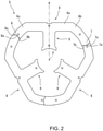
FIG. 2 is a plan view illustrating a schematic configuration of a first laminated member. -
FIG. 3 is a plan view illustrating a schematic configuration of a second laminated member. -
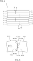
FIG. 4 is a partial side view illustrating a connection state between core pieces. -
FIG. 5 is a partially enlarged plan view illustrating a state in which radial positions of core pieces are adjusted in the first embodiment. -
FIG. 6(a) is a plan view showing the shape of a first laminated member andFIG. 6(b) is a plan view showing the shape of a second laminated member, in a second embodiment. -
FIG. 7 is a partially enlarged plan view illustrating a state in which radial positions of core pieces are adjusted in the second embodiment. -
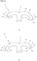
FIG. 8(a) is a plan view illustrating the shape of a first laminated member, andFIG. 8(b) is a plan view illustrating the shape of a second laminated member, in a third embodiment. -
FIG. 9 is a partial plan view illustrating a connection state between core pieces in the third embodiment. - Hereinafter, an embodiment of the present invention will be described in detail with reference to the drawings. The same or corresponding parts in the drawings are denoted by the same reference numerals, and the description thereof will not be repeated. Further, the dimensions of constituent members in each drawing do not faithfully represent the actual dimensions of the constituent members, the dimensional ratio of each constituent member, or the like.
- Further, in the description provided below, a direction parallel to the central axis P of a stator core 1 is referred to as an "axial direction", "axial", or "axially", a direction orthogonal to the central axis P is referred to as a "radial direction", "radial", or "radially", and a direction along an arc with the central axis P as the center is referred to as a "circumferential direction", "circumferential", or "circumferentially". However, there is no intention to limit the direction at the time of use of the stator core 1 according to the invention by these definitions of the directions.
- Further, in the following description, the expressions such as "fixed", "connected", "joined" and "attached" (hereinafter referred to as "fixed" or the like) are not limited to the case where the members are directly fixed or the like to each other. It also includes the case where it is fixed or the like via another member. That is, in the following description, the expression such as fixation includes the meaning of direct and indirect fixation or the like between members.
- An embodiment of the present invention relates to a configuration of a stator core 1 used for a motor. In the present specification, the "stator core 1" refers to a set of a plurality of
core pieces 2 in a state of being annularly connected around the central axis P. The "core piece 2" refers to a portion having the teeth 4 around which no conductive wire is wound and a core back portion that becomes annular in a connected state. Each layer of thecore piece 2 forming thecore piece 2 by being laminated is referred to as a "laminated member". The "laminated member" does not necessarily refer to a member having only one layer of the members constituting thecore piece 2, and includes a member having a plurality of layers having the same shape or substantially the same shape and continuously laminated. -
FIG. 1 shows a schematic configuration of the stator core 1 according to an embodiment of the present invention. - As illustrated in
FIG. 1 , the stator core 1 is an iron core constituting a stator. The stator core 1 includes a plurality ofcore pieces 2 annularly arranged around the central axis P. The stator core 1 has threecore pieces 2. Eachcore piece 2 includes asegment core back 3 constituting a part of a cylindrical core back, and a tooth 4. - The number of
core pieces 2 constituting the stator core 1 is appropriately determined according to the number of teeth 4. That is, when the number of teeth 4 of the stator core 1 is larger than three, the number ofcore pieces 2 is larger than three. - The
core piece 2 includes a first laminatedmember 5 and a second laminatedmember 10 made of electromagnetic steel sheets. In thecore piece 2, two first laminatedmembers 5 and two second laminatedmembers 10 are alternately laminated in the thickness direction. In the present embodiment, as long as thecore piece 2 has a configuration in which the first laminatedmember 5 and the second laminatedmember 10 are alternately laminated, the number of units of the first laminatedmember 5 and the second laminatedmember 10 to be laminated or the like may be arbitrarily set. The first laminatedmember 5 and the second laminatedmember 10 are connected to each other by being caulked at a caulking portion 2a in a state of being alternately laminated in the thickness direction. - A circumferential end of the segment core back 3 in one
core piece 2 contacts a circumferential end of the segment core back 3 of anothercore piece 2 adjacent to the segment core back 3 in the circumferential direction. As a result, an annular core back of the stator core 1 is configured of the segment core backs 3 in the plurality ofcore pieces 2. In this manner, the plurality ofcore pieces 2 are in contact with each other to constitute the stator core 1 including the core back configured of the plurality of segment core backs 3 and the plurality of teeth 4. - Next, the first
laminated member 5 and the secondlaminated member 10 constituting thecore piece 2, and thecore piece 2 will be described in detail with reference toFIGS. 2 to 4 . - As illustrated in
FIG. 2 , the firstlaminated member 5 of thecore piece 2 includes a first core backportion 6 and afirst tooth portion 9. - The first core back
portion 6 is a portion constituting an annular portion of the stator core 1. The first core backportion 6 includes astraight portion 6a extending in a direction perpendicular to a straight line A with the straight line A passing through the central axis P being the center, and a first-side arc portion 6b and a second-side arc portion 6c extending from both ends of thestraight portion 6a along a circumferential direction of an arc with the central axis P being the center. Thestraight portion 6a is line-symmetric with respect to the straight line A. That is, thestraight portion 6a extends with an equal length in both directions with the straight line A as a symmetry line. The first-side arc portion 6b extending from the first-side end of thestraight portion 6a is longer than the second-side arc portion 6c extending from the second-side end of thestraight portion 6a by a predetermined length in the circumferential direction. - The first core back
portion 6 has afirst protrusion 7 protruding in the circumferential direction at the first-side end in the circumferential direction. Thefirst protrusion 7 has avertex 7a protruding in the circumferential direction. In addition, thefirst protrusion 7 includes, as linear first protrusion-side contact portions, a protrusion-side upwardinclined surface 7b extending from the inner periphery of the first core backportion 6 toward thevertex 7a of thefirst protrusion 7, and a protrusion-side downwardinclined surface 7c extending from the outer periphery of the first core backportion 6 toward thevertex 7a of thefirst protrusion 7. That is, thefirst protrusion 7 has a shape including a gradient in which the radius from the central axis P increases radially inward with thevertex 7a being interposed therebetween, and a gradient in which the radius from the central axis P decreases radially outward with thevertex 7a being interposed therebetween. - The first core back
portion 6 has afirst recess 8 that is recessed in the circumferential direction at the second-side end in the circumferential direction. Thefirst recess 8 has avertex 8a recessed in the circumferential direction. In addition, thefirst recess 8 has, as linear first recess-side contact portions, a recess-side upwardinclined surface 8b extending from the inner periphery of the first core backportion 6 to thevertex 8a of thefirst recess 8, and a recess-side downwardinclined surface 8c extending from the outer periphery of the first core backportion 6 to thevertex 8a of thefirst recess 8. That is, thefirst recess 8 has a shape including a gradient in which the radius from the central axis P increases radially inward with thevertex 8a being interposed therebetween, and a gradient in which the radius from the central axis P decreases radially outward with thevertex 8a being interposed therebetween. The outer shape of the first recess-side contact portion is the same as the outer shape of the first protrusion-side contact portion. As a result, to thefirst recess 8 of the first core backportion 6, thefirst protrusion 7 of the adjacent first core backportion 6 is fitted, whereby the first recess-side contact portion and the first protrusion-side contact portion come into contact with each other. - The
first tooth portion 9 is a portion constituting one of the plurality of teeth 4 of the stator core 1. Thefirst tooth portion 9 extends radially inward from the center of thestraight portion 6a of the first core backportion 6. Thefirst tooth portion 9 is line-symmetric with the straight line A passing through the central axis P being the center. Thefirst tooth portion 9 has a shape in which a radially inner end portion expands in the circumferential direction. - As illustrated in
FIG. 3 , the secondlaminated member 10 of thecore piece 2 includes a second core backportion 11 and asecond tooth portion 14. - The second core back
portion 11 is a portion constituting an annular portion of the stator core 1. The second core backportion 11 includes astraight portion 11a extending in a direction perpendicular to the straight line A with the straight line A passing through the central axis P being the center, and a first-side arc portion 11b and a second-side arc portion 11c respectively extending from both ends of thestraight portion 11a along a circumferential direction of an arc with the central axis P being the center. Thestraight portion 11a is line-symmetric with respect to the straight line A. That is, thestraight portion 11a extends with an equal length in both directions with the straight line A as a symmetry line. The first-side arc portion 11b extending from a first-side end of thestraight portion 11a is shorter than the second-side arc portion 11c extending from a second-side end of thestraight portion 11a by a predetermined length in the circumferential direction. - The second core back
portion 11 has asecond protrusion 12 protruding in the circumferential direction at the first-side end in the circumferential direction. Thesecond protrusion 12 has avertex 12a protruding in the circumferential direction. In addition, thesecond protrusion 12 includes, as linear second protrusion-side contact portions, a protrusion-side upwardinclined surface 12b extending from the inner periphery of the second core backportion 11 toward thevertex 12a of thesecond protrusion 12, and a protrusion-side downwardinclined surface 12c extending from the outer periphery of the second core backportion 11 toward thevertex 12a of thesecond protrusion 12. That is, thesecond protrusion 12 has a shape including a gradient in which the radius from the central axis P increases radially inward with thevertex 12a interposed therebetween, and a gradient in which the radius from the central axis P decreases radially outward with thevertex 12a interposed therebetween. - The second core back
portion 11 has asecond recess 13 that is recessed in the circumferential direction at the second-side end in the circumferential direction. Thesecond recess 13 has avertex 13a recessed in the circumferential direction. In addition, thesecond recess 13 includes, as a linear second recess-side contact portion, a recess-side upwardinclined surface 13b extending from the inner periphery of the second core backportion 11 toward thevertex 13a of thesecond recess 13, and a recess-side downwardinclined surface 13c extending from the outer periphery of the second core backportion 11 toward thevertex 13a of thesecond recess 13. That is, thesecond recess 13 has a shape including a gradient in which the radius from the central axis P increases radially inward with thevertex 13a being interposed therebetween, and a gradient in which the radius from the central axis P decreases radially outward with thevertex 13a being interposed therebetween. The outer shape of the second recess-side contact portion is the same as the outer shape of the second protrusion-side contact portion. As a result, to thesecond recess 13 of the second core backportion 11, thesecond protrusion 12 of the adjacent second core backportion 11 is fitted, whereby the second recess-side contact portion and the second protrusion-side contact portion come into contact with each other. - The
second tooth portion 14 is a portion constituting one of the plurality of teeth 4 of the stator core 1. Thesecond tooth portion 14 extends radially inward from the center of thestraight portion 11a of the second core backportion 11. Thesecond tooth portion 14 is line-symmetric about the straight line A passing through the central axis P. Thesecond tooth portion 14 has a shape in which a radially inner end portion expands in the circumferential direction. - In each embodiment of the present application, each of the
vertex 7a of thefirst protrusion 7 and thevertex 12a of thesecond protrusion 12 refers to a portion where an inclined surface and an inclined surface intersect with each other, but it is not limited to a portion where a plane and a plane intersect with each other, and may be the center of a portion protruding most in the circumferential direction. For example, a case where thevertex 7a or thevertex 12a is a curved surface, and a case where thefirst protrusion 7 or thesecond protrusion 12 has an arc shape or a trapezoidal shape are also included. When thevertex 7a of thefirst protrusion 7 or thevertex 12a of the second protrusion is a curved surface, a virtual point which is an intersection of a tangent and a tangent of the curved surface is included. When thefirst protrusion 7 or thesecond protrusion 12 has a trapezoidal shape or the like and a portion protruding most in the circumferential direction is flat, the center of the flat portion is set. - In each embodiment of the present application, each of the
vertex 8a of thefirst recess 8 and thevertex 13a of thesecond recess 13 refers to a portion where an inclined surface and an inclined surface intersect with each other, but it is not limited to a portion where a plane and a plane intersect with each other, and may be at the center of a portion that is recessed most in the circumferential direction. For example, a case where thevertex 8a or thevertex 13a is a curved surface or a case where thefirst recess 8 or thesecond recess 13 has an arc shape or a trapezoidal shape is also included. In a case where thevertex 8a or thevertex 13a is a curved surface, a virtual point which is an intersection of a tangent and a tangent of the curved surface is included. When thefirst recess 8 or thesecond recess 13 has a trapezoidal shape or the like and the portion recessed most in the circumferential direction is flat, the center of the flat portion is set. - As illustrated in
FIG. 1 , a predetermined number of the firstlaminated members 5 and a predetermined number of the secondlaminated members 10 are alternately laminated two by two. The firstlaminated member 5 and the secondlaminated member 10 are laminated with thefirst tooth portion 9 and thesecond tooth portion 14 coinciding with each other. The segment core back 3 of thecore piece 2 includes the first core backportion 6 of the firstlaminated member 5 and the second core backportion 11 of the secondlaminated member 10 that are laminated. The teeth 4 of thecore piece 2 include thefirst tooth portion 9 of the firstlaminated member 5 and thesecond tooth portion 14 of the secondlaminated member 10 that are laminated. - As illustrated in
FIGS. 2 to 4 , in the first core backportion 6 of the firstlaminated member 5, the length of the first-side arc portion 6b is longer than the length of the second-side arc portion 6c by a predetermined length. Similarly, in the second core backportion 11 of the secondlaminated member 10, the length of the first-side arc portion 11b is shorter than the length of the second-side arc portion 11c by a predetermined length. Therefore, in thecore piece 2, both circumferential end positions of the first core backportion 6 are different from both circumferential end positions of the second core backportion 11. At the first side in the circumferential direction of thecore piece 2, the first core backportion 6 protrudes in the circumferential direction from the second core backportion 11. At the second side in the circumferential direction of thecore piece 2, the second core backportion 11 protrudes in the circumferential direction from the first core backportion 6. That is, the first core backportions 6 are disposed in a comb-teeth shape on the first side in the circumferential direction of thecore piece 2. The second core backportions 11 are disposed in a comb-teeth shape on the second side in the circumferential direction of thecore piece 2. - As illustrated in
FIG. 4 , the first-side end in the circumferential direction of the segment core back 3 in onecore piece 2 is connected to the second-side end in the circumferential direction of the segment core back 3 in anothercore piece 2 adjacent to the first side in the circumferential direction. At the first-side end in the circumferential direction of the segment core back 3, the second core backportion 11 of the adjacent segment core back 3 enters between the first core backportion 6 and the first core backportion 6. Further, the second-side end in the circumferential direction of the segment core back 3 in onecore piece 2 is connected with the first-side end in the circumferential direction of the segment core back 3 in anothercore piece 2 adjacent to the second side in the circumferential direction. At the second-side end in the circumferential direction of the segment core back 3, the first core backportion 6 of the adjacent segment core back 3 enters between the second core backportion 11 and the second core backportion 11. As a result, one core piece and anothercore piece 2 adjacent thereto in the circumferential direction are connected with each other in a state where the first core backportion 6 and the second core backportion 11 overlap each other in the thickness direction. - As illustrated in
FIGS. 2 and3 , in the segment core back 3 in onecore piece 2, the first core backportion 6 is in contact with the first core backportion 6 of the segment core back 3 of anothercore piece 2 adjacent thereto, and the second core backportion 11 is in contact with the second core backportion 11 of the segment core back 3 of anothercore piece 2 adjacent thereto. That is, between the segment core back 3 of onecore piece 2 and the segment core back 3 of anothercore piece 2 adjacent thereto, thefirst protrusion 7 of the first core backportion 6 and thefirst recess 8 of the first core backportion 6 adjacent thereto face each other, and thesecond protrusion 12 of the second core backportion 11 and thesecond recess 13 of the second core backportion 11 adjacent thereto face each other. - Further, the
first protrusion 7 of the first core backportion 6 in onecore piece 2 is in contact with thefirst recess 8 of the first core backportion 6 in anothercore piece 2 adjacent thereto. Thefirst recess 8 of the first core backportion 6 in onecore piece 2 is in contact with thefirst protrusion 7 of the first core backportion 6 in anothercore piece 2 adjacent thereto. Similarly, thesecond protrusion 12 of the second core backportion 11 in onecore piece 2 is in contact with thesecond recess 13 of the second core backportion 11 in anothercore piece 2 adjacent thereto. Thesecond recess 13 of the second core backportion 11 in onecore piece 2 is in contact with thesecond protrusion 12 of the second core backportion 11 in anothercore piece 2 adjacent thereto. - As illustrated in
FIG. 5 , between thefirst protrusion 7 of the first core backportion 6 and thefirst recess 8 of the first core backportion 6 adjacent thereto, the first protrusion-side contact portion and the first recess-side contact portion are in contact with each other. That is, between thefirst protrusion 7 and thefirst recess 8, the protrusion-side upwardinclined surface 7b of the first protrusion-side contact portion and the recess-side upwardinclined surface 8b of the first recess-side contact portion are in contact with each other, and the protrusion-side downwardinclined surface 7c of the first protrusion-side contact portion and the recess-side downwardinclined surface 8c of the first recess-side contact portion are in contact with each other. That is, thefirst protrusion 7 and thefirst recess 8 are in contact with each other at two positions, that is, the protrusion-side upwardinclined surface 7b and the recess-side upwardinclined surface 8b on the radially inner side, and the protrusion-side downwardinclined surface 7c and the recess-side downwardinclined surface 8c on the radially outer side, with thevertex 7a of thefirst protrusion 7 being interposed therebetween. - Between the
second protrusion 12 of the second core backportion 11 and thesecond recess 13 of the second core backportion 11 adjacent thereto, the second protrusion-side contact portion and the second recess-side contact portion are in contact with each other. That is, between thesecond protrusion 12 and thesecond recess 13, the protrusion-side upwardinclined surface 12b of the second protrusion-side contact portion and the recess-side upwardinclined surface 13b of the second recess-side contact portion are in contact with each other, and the protrusion-side downwardinclined surface 12c of the second protrusion-side contact portion and the recess-side downwardinclined surface 13c of the second recess-side contact portion are in contact with each other. That is, thesecond protrusion 12 and thesecond recess 13 are in contact with each other at two positions, that is, the protrusion-side upwardinclined surface 12b and the recess-side upwardinclined surface 13b on the radially inner side, and the protrusion-side downwardinclined surface 12c and the recess-side downwardinclined surface 13c on the radially outer side, with thevertex 12a of thesecond protrusion 12 being interposed therebetween. - When a circumferential force indicated by a black arrow is applied to the segment core back 3 of one
core piece 2 and the segment core back 3 of anothercore piece 2 adjacent thereto, in the first core backportion 6 which is a part of the segment core back 3, a component force toward thevertex 8a of thefirst recess 8 indicated by an arrow along the recess-side upwardinclined surface 8b and a component force toward thevertex 8a of thefirst recess 8 indicated by an arrow along the recess-side downwardinclined surface 8c are generated with respect to the adjacent first core backportion 6. The radial position of the first core backportion 6 with respect to the adjacent first core backportion 6 is determined by the balance between the radially outward force from the radially inner side toward thevertex 8a of thefirst recess 8 and the radially inward force from the radially outer side toward thevertex 8a of thefirst recess 8. Similarly, in the second core backportion 11 that is a part of the segment core back 3, the radial position with respect to the adjacent second core backportion 11 is determined by the balance between the component force from the radially inner side indicated by an arrow toward thevertex 13a of thesecond recess 13 and the component force from the radially outer side toward thevertex 13a of thesecond recess 13. That is, the position of onecore piece 2 in the radial direction with respect to theother core pieces 2 adjacent thereto is determined by applying a force in the circumferential direction. - In the stator core 1 including the plurality of
core pieces 2, thefirst protrusion 7 of the first core backportion 6 and thefirst recess 8 of the first core backportion 6 adjacent thereto, and thesecond protrusion 12 of the second core backportion 11 and thesecond recess 13 of the second core backportion 11 adjacent thereto, in the segment core back 3 of one core piece, are in contact with each other only at two positions with the vertex of each protrusion being interposed therebetween, so that the alignment function by the radially inward force and the radially outward force is not hindered. In addition, since the linear first protrusion-side contact portion and the linear first recess-side contact portion are in contact with each other, and the linear second protrusion-side contact portion and the linear second recess-side contact portion are in contact with each other, the radially inward force and the radially outward force are determined by the shapes of thefirst protrusion 7 and thesecond protrusion 12 and thefirst recess 8 and thesecond recess 13. As a result, the radial position between thecore pieces 2 can be adjusted to an appropriate position. - Next, a stator core 1 that is a second embodiment of the stator core 1 according to the present invention will be described with reference to
FIGS. 6 and7 . The stator core 1 according to the following embodiment is applied in place of the stator core 1 in the stator core 1 illustrated inFIGS. 1 to 7 , and the names, figure numbers, and reference numerals used in the description are used to indicate the same components. In the following embodiment, specific description of the same points as those of the embodiment already described will be omitted, and different points will be mainly described. - As illustrated in
FIG. 6(a) , the first core backportion 6 has afirst protrusion 15 protruding in the circumferential direction at first-side end in the circumferential direction. Thefirst protrusion 15 has an arc portion protruding in the circumferential direction. - In the
first protrusion 15, a point protruding most in the circumferential direction in the arc portion is defined as avertex 15a. Thefirst protrusion 15 has, as a first protrusion-side contact portion, a protrusion-side upwardcurved surface 15b extending from the inner periphery of the first core backportion 6 toward thevertex 15a of thefirst protrusion 15, and a protrusion-side downwardcurved surface 15c extending from the outer periphery of the first core backportion 6 toward thevertex 15a of thefirst protrusion 15. - As illustrated in
FIG. 6(b) , the second core backportion 11 has asecond protrusion 16 protruding in the circumferential direction at first-side end in the circumferential direction. Thesecond protrusion 16 has an arc portion protruding in the circumferential direction. In thesecond protrusion 16, a point that protrudes most in the circumferential direction in the arc portion is defined as avertex 16a. Thesecond protrusion 16 has, as a second protrusion-side contact portion, a protrusion-side upwardcurved surface 16b extending from the inner periphery of the second core backportion 11 toward thevertex 16a of thesecond protrusion 16, and a protrusion-side downwardcurved surface 16c extending from the outer periphery of the second core backportion 11 toward thevertex 16a of thesecond protrusion 16. - As illustrated in
FIG. 7 , between thefirst protrusion 15 of the first core backportion 6 and thefirst recess 8 of the first core backportion 6 adjacent thereto, the protrusion-side upwardcurved surface 16b of the first protrusion-side contact portion and the recess-side upwardinclined surface 8b of the first recess-side contact portion are in contact with each other, and the protrusion-side downwardcurved surface 16c of the first protrusion-side contact portion and the recess-side downwardinclined surface 8c of the first recess-side contact portion are in contact with each other. That is, thefirst protrusion 15 of the first core backportion 6 is in contact with the linear first recess-side contact portion of the adjacent first core backportion 6. Thefirst protrusion 15 and thefirst recess 8 are in contact with each other at two positions, that is, the protrusion-side upwardcurved surface 16b and the recess-side upwardinclined surface 8b on the radially inner side, and the protrusion-side downwardcurved surface 16c and the recess-side downwardinclined surface 8c on the radially outer side, with thevertex 15a of thefirst protrusion 15 being interposed therebetween. - Between the
second protrusion 16 of the second core backportion 11 and thesecond recess 13 of the adjacent second core backportion 11, the protrusion-side upwardcurved surface 16b of the second protrusion-side contact portion and the recess-side upwardinclined surface 8b of the second recess-side contact portion, and the protrusion-side downwardcurved surface 16c of the second protrusion-side contact portion and the recess-side downwardinclined surface 8c of the second recess-side contact portion are in contact with each other. That is, thesecond protrusion 16 of the second core backportion 11 is in contact with the linear second recess-side contact portion of the adjacent second core backportion 11. Thesecond protrusion 16 and thesecond recess 13 are in contact with each other at two positions, that is, the protrusion-side upwardcurved surface 16b and the recess-side upwardinclined surface 8b on the radially inner side, and the protrusion-side downwardcurved surface 16c and the recess-side downwardinclined surface 8c on the radially outer side, with thevertex 16a of thesecond protrusion 16 being interposed therebetween. - With such a configuration, the linear first recess-side contact portion of the first
core hack portion 6 comes into contact with thefirst protrusion 15 of the adjacent firstcore hack portion 6, and the linear second recess-side contact portion of the second core backportion 11 comes into contact with thesecond protrusion 16 of the adjacent second core backportion 11. Therefore, the radially inward force and the radially outward force are determined by the shapes of the first recess-side contact portion and the second recess-side contact portion. As a result, the radial position between thecore pieces 2 can be adjusted to an appropriate position. - Next, a stator core 1 that is a third embodiment of the stator core 1 according to the present invention will be described with reference to
FIGS. 8 and9 . - As illustrated in
FIG. 8(a) , the first core backportion 6 has a first first-sideuneven portion 17 formed of a curved surface in which an arc-shaped protrusion protruding in the circumferential direction and an arc-shaped recess recessed in the circumferential direction continue at a first-side end in the circumferential direction. The first first-sideuneven portion 17 has a protrusion-sidecurved surface 17a protruding in the circumferential direction as a first protrusion-side contact portion, and has a recess-sidecurved surface 17b recessed in the circumferential direction as a first recess-side contact portion. In addition, the first core backportion 6 has a first second-sideuneven portion 18 formed of a curved surface in which an arc-shaped protrusion protruding in the circumferential direction and an arc-shaped recess recessed in the circumferential direction continue at a second-side end in the circumferential direction. The first second-sideuneven portion 18 has a protrusion-sidecurved surface 18a protruding in the circumferential direction as the first protrusion-side contact portion, and has a recess-sidecurved surface 18b recessed in the circumferential direction as the first recess-side contact portion. - At the first-side end in the circumferential direction of the first core back
portion 6, the first protrusion-side contact portion and the first recess-side contact portion are arranged from the radially outer side toward the radially inner side. At the second-side end in the circumferential direction of the first core backportion 6, the first recess-side contact portion and the first protrusion-side contact portion are arranged from the radially outer side toward the radially inner side. The outer shape of the first recess-side contact portion is the same as the outer shape of the first protrusion-side contact portion. As a result, the first first-sideuneven portion 17 of the first core backportion 6 is fitted to the first second-sideuneven portion 18 of the adjacent first core backportion 6. - As illustrated in
FIG. 8(b) , the second core backportion 11 has a second first-sideuneven portion 19 formed of a curved surface in which an arc-shaped protrusion protruding in the circumferential direction and an arc-shaped recess recessed in the circumferential direction continue at the first-side end in the circumferential direction. The second first-sideuneven portion 19 has a protrusion-sidecurved surface 19a protruding in the circumferential direction as the second protrusion-side contact portion, and has a recess-sidecurved surface 19b recessed in the circumferential direction as the second recess-side contact portion. In addition, the second core backportion 11 has a second second-sideuneven portion 20 formed of a curved surface in which an arc-shaped protrusion protruding in the circumferential direction and an arc-shaped recess recessed in the circumferential direction continue at the second-side end in the circumferential direction. The second second-sideuneven portion 20 has a protrusion-sidecurved surface 20a protruding in the circumferential direction as the second protrusion-side contact portion, and has a recess-sidecurved surface 20b recessed in the circumferential direction as the second recess-side contact portion. - At the first-side end in the circumferential direction of the second core back
portion 11, the second protrusion side contact portion and the second recess-side contact portion are arranged from the radially outer side toward the radially inner side. At the second-side end in the circumferential direction of the second core backportion 11, the second recess-side contact portion and the second protrusion-side contact portion are arranged from the radially outer side toward the radially inner side. The outer shape of the second recess-side contact portion is the same as the outer shape of the second protrusion-side contact portion. As a result, the seconduneven portion 18 of the second core backportion 11 is fitted to the seconduneven portion 18 of the adjacent second core backportion 11 without any gap. - As illustrated in
FIG. 9 , between the first first-sideuneven portion 17 of the first core backportion 6 and the first second-sideuneven portion 18 of the adjacent first core backportion 6, the first protrusion-side contact portion and the first recess-side contact portion are in contact with each other. That is, at the first-side end in the circumferential direction of the first core backportion 6, the first protrusion-side contact portion on the radially outer side is in contact with the first recess-side contact portion of the adjacent first core backportion 6. Further, at the first-side end in the circumferential direction of the first core backportion 6, the first recess-side contact portion on the radially inner side is in contact with the first protrusion-side contact portion of the adjacent first core backportion 6. Further, at the second-side end in the circumferential direction of the first core backportion 6, the first recess-side contact portion on the radially outer side is in contact with the first protrusion-side contact portion of the adjacent first core backportion 6. Furthermore, at the second-side end in the circumferential direction of the first core backportion 6, the first protrusion-side contact portion on the radially inner side is in contact with the first recess-side contact portion of the adjacent first core backportion 6. - Between the second first-side
uneven portion 19 of the second core backportion 11 and the second second-sideuneven portion 20 of the adjacent second core backportion 11, the second protrusion-side contact portion and the second recess-side contact portion are in contact with each other. That is, at the first-side end in the circumferential direction of the second core backportion 11, the second protrusion-side contact portion on the radially outer side is in contact with the second recess-side contact portion of the adjacent second core backportion 11. Further, at the first-side end in the circumferential direction of the second core backportion 11, the second recess-side contact portion on the radially inner side is in contact with the second protrusion-side contact portion of the adjacent second core backportion 11. At the second-side end in circumferential direction of the second core backportion 11, the second recess-side contact portion on the radially outer side is in contact with the second protrusion-side contact portion of the adjacent second core backportion 11. Further, at the second-side end in the circumferential direction of the second core backportion 11, the second protrusion-side contact portion on the radially inner side is in contact with the second recess-side contact portion of the adjacent second core backportion 11. - In the stator core 1 including the plurality of
core pieces 2, the first recess-side contact portion and the first protrusion-side contact portion, and the second recess-side contact portion and the second protrusion-side contact portion, which are aligned in the radial direction of the first core backportion 6 and the second core backportion 11, are in contact with each other, so that the relative position between thecore pieces 2 is determined. As a result, the axial positional deviation between thecore pieces 2 can be suppressed, and the radial position of thecore piece 2 can be adjusted to an appropriate position. - In the first embodiment, the first core back
portion 6 has thefirst protrusion 7 at the first-side end in the circumferential direction and thefirst recess 8 at the second-side end in the circumferential direction, but the positions of thefirst protrusion 7 and thefirst recess 8 in the first core backportion 6 are not limited. Regarding the first core backportion 6 and the first core hack portion of thecore piece 2 adjacent thereto in the circumferential direction, it is only necessary that either one of them has thefirst protrusion 7 and the other has thefirst recess 8 and that thefirst protrusion 7 and thefirst recess 8 face each other. For example, the first core backportion 6 may have thefirst protrusions 7 or thefirst recesses 8 on both side ends. The same applies to the second core backportion 11. Further, the arrangement of thefirst protrusion 7 and thefirst recess 8 in the first core backportion 6 does not define the arrangement of thesecond protrusion 12 and thesecond recess 13 in the second core backportion 11. That is, thefirst protrusion 7 may be provided at a first-side end in the circumferential direction of the first core backportion 6, and thesecond recess 13 may be provided at the first-side end in the circumferential direction of the second core backportion 11. Also in the second embodiment, the positions and shapes of the first first-side uneven portion and the first second-side uneven portion of the first core backportion 6 are not limited. - The annular stator core 1 configured as described above includes the
core piece 2 in which at least the firstlaminated member 5 and the secondlaminated member 10 are laminated in the first embodiment. The firstlaminated member 5 includes the first core backportion 6 extending in the circumferential direction and afirst tooth portion 9 extending radially inward from the firstcore bag portion 6. The secondlaminated member 10 includes the second core backportion 11 extending in the circumferential direction and thesecond tooth portion 14 extending radially inward from the second core backportion 11. Both end positions in the circumferential direction of the first core backportion 6 are different from both end positions in the circumferential direction of the second core backportion 11. One of the first core back portion 6 and the first core back portion 6 of the core piece 2 adjacent thereto in the circumferential direction has the first protrusion 7 protruding in the circumferential direction, the other of the first core back portion 6 and the first core back portion 6 of the core piece 2 adjacent thereto has the first recess 8 recessed in the circumferential direction, the first protrusion 7 and the first recess 8 face each other, one of the second core back portion 11 and the second core back portion 11 of the core piece 2 adjacent thereto has the second protrusion 12 protruding in the circumferential direction, and the other of the second core back portion 11 and the second core back portion 11 of the core piece 2 adjacent thereto has the second recess 13 recessed in the circumferential direction, the second protrusion 12 and the second recess 13 face each other, the first core back portion 6 and the first core back portion 6 of the core piece 2 adjacent thereto are in contact with each other on the radially outer side and the radially inner side sandwiching the vertex 7a of the first protrusion 7, and the second core back portion 11 and the second core back portion 11 of the core piece 2 adjacent thereto is in contact with each other on the radially outer side and the radially inner side sandwiching the vertex 12a of the second protrusion 12. - Since the one
core piece 2 and theother core piece 2 adjacent thereto that are configured as described above are configured such that both end positions in the circumferential direction of the firstlaminated member 5 and the secondlaminated member 10 constituting thecore piece 2 are alternately arranged, theadjacent core pieces 2 are meshed with each other and connected to each other, and the position in the central axis P direction is determined. In addition, since thefirst protrusion 7 and thefirst recess 8 of the first core backportion 6 and thesecond protrusion 12 and thesecond recess 13 of the second core backportion 11 are in contact with each other at two positions sandwiching the vertex of each protrusion, a radially inward force and a radially outward force are generated in the first core backportion 6 and the second core backportion 11. As a result, the stator core 1 can suppress the axial positional deviation between thecore pieces 2 and adjust the radial position between thecore pieces 2 to an appropriate position only by connecting thecore pieces 2 to each other. - The above-described embodiments are merely representative forms, and various modifications can be made without departing from the gist of one embodiment. It goes without saying that the present invention can be implemented in various forms, and the scope of the present invention is indicated by the description of the claims, and further includes equivalent meanings described in the claims and all modifications within the scope.
- The present invention is applicable to the annular stator core 1.
-
- 1
- stator core
- 2
- core piece
- 5
- first laminated member
- 6
- first core back portion
- 7
- first protrusion
- 8
- first recess
- 9
- first tooth portion
- 10
- second laminated member
- 11
- second core back portion
- 12
- second protrusion
- 12a
- vertex
- 13
- second recess
- 14
- second tooth portion
Claims (5)
- A stator core in an annular shape extending along a central axis, the stator core comprisinga core piece in which at least a first laminated member and a second laminated member are laminated, whereinthe first laminated member includes:a first core back portion extending in a circumferential direction; anda first tooth portion extending radially inward from the first core bag portion,the second laminated member includes:a second core back portion extending in the circumferential direction; anda second tooth portion extending radially inward from the second core bag portion,both circumferential end positions of the first core back portion are different from both circumferential end positions of the second core back portion,one of the first core back portion and a first core back portion of an adjacent core piece in the circumferential direction has a first protrusion protruding in the circumferential direction,another of the first core back portion and the first core back portion of the adjacent core piece has a first recess recessed in the circumferential direction,the first protrusion and the first recess face each other,one of the second core back portion and a second core back portion of the adjacent core piece has a second protrusion protruding in the circumferential direction,another of the second core back portion and the second core back portion of the adjacent core piece has a second recess recessed in the circumferential direction,the second protrusion and the second recess face each other,the first core back portion and the first core back portion of the adjacent core piece are in contact with each other on a radially outer side and on a radially inner side sandwiching a vertex of the first protrusion, andthe second core back portion and the second core back portion of the adjacent core piece are in contact with each other on a radially outer side and on a radially inner side sandwiching a vertex of the second protrusion.
- The stator core according to claim 1, whereinbetween the first core back portion and the first core back portion of the adjacent core piece, the first recess contacts at two positions on the radially outer side and the radially inner side sandwiching the vertex of the first protrusion, andbetween the second core back portion and the second core back portion of the adjacent core piece, the second recess contacts at two positions on the radially outer side and the radially inner side sandwiching the vertex of the second protrusion.
- The stator core according to claim 1 or 2, whereinthe first recess includes a first recess-side contact portion in a linear shape,the second recess includes a second recess-side contact portion in a linear shape,the first recess-side contact portion is in contact with the first protrusion of the first core back portion of the adjacent core piece, andthe second recess-side contact portion is in contact with the second protrusion of the second core back portion in the adjacent core piece.
- The stator core according to any one of claims 1 to 3, whereinthe first protrusion includes a first protrusion-side contact portion in a linear shape,the second protrusion includes a second protrusion-side contact portion in a linear shape,the first protrusion-side contact portion is in contact with the first recess-side contact portion of the first core back portion of the adjacent core piece, andthe second protrusion-side contact portion is in contact with the second recess-side contact portion of the second core back portion in the adjacent core piece.
- A stator core in an annular shape extending along a central axis, the stator core comprisinga core piece in which at least a first laminated member and a second laminated member are laminated, whereinthe first laminated member includes:a first core back portion extending in a circumferential direction; anda first tooth portion extending radially inward from the first core bag portion,the second laminated member includes:a second core back portion extending in the circumferential direction; anda second tooth portion extending radially inward from the second core bag portion,when viewed from an axial direction, both circumferential end positions of the first core back portion and both circumferential end positions of the second core back portion are different,the first core back portion includes a first uneven portion formed of a curved surface continuous with both side ends in the circumferential direction,the second core back portion includes a second uneven portion formed of a curved surface continuous with both side ends in the circumferential direction,the first uneven portion of the first core back portion and a first uneven portion of a first core back portion of an adjacent core piece are in contact with each other, andthe second uneven portion of the second core back portion and a second uneven portion of a second core back portion of the adjacent core piece are in contact with each other.
Applications Claiming Priority (2)
| Application Number | Priority Date | Filing Date | Title |
|---|---|---|---|
| JP2019063587 | 2019-03-28 | ||
| PCT/JP2020/003709 WO2020195158A1 (en) | 2019-03-28 | 2020-01-31 | Stator core |
Publications (2)
| Publication Number | Publication Date |
|---|---|
| EP3952063A1 true EP3952063A1 (en) | 2022-02-09 |
| EP3952063A4 EP3952063A4 (en) | 2022-12-14 |
Family
ID=72608582
Family Applications (1)
| Application Number | Title | Priority Date | Filing Date |
|---|---|---|---|
| EP20778532.0A Withdrawn EP3952063A4 (en) | 2019-03-28 | 2020-01-31 | STATOR CORE |
Country Status (5)
| Country | Link |
|---|---|
| US (1) | US20220166266A1 (en) |
| EP (1) | EP3952063A4 (en) |
| JP (1) | JP7435591B2 (en) |
| CN (1) | CN113646992B (en) |
| WO (1) | WO2020195158A1 (en) |
Family Cites Families (17)
| Publication number | Priority date | Publication date | Assignee | Title |
|---|---|---|---|---|
| JP3461552B2 (en) | 1994-01-28 | 2003-10-27 | 多摩川精機株式会社 | Method of manufacturing stator and split laminated core |
| JP4916730B2 (en) * | 2006-02-07 | 2012-04-18 | アスモ株式会社 | Stator manufacturing method and stator |
| WO2008044740A1 (en) * | 2006-10-13 | 2008-04-17 | Mitsui High-Tec, Inc. | Laminated iron core, and its manufacturing method |
| JP5020034B2 (en) * | 2007-11-22 | 2012-09-05 | 三菱電機株式会社 | Rotating electric machine |
| JP5171224B2 (en) * | 2007-11-22 | 2013-03-27 | 三菱電機株式会社 | Rotating electric machine |
| JP5776170B2 (en) * | 2010-12-01 | 2015-09-09 | 日本電産株式会社 | Stator core and motor |
| JP5660058B2 (en) * | 2012-01-31 | 2015-01-28 | 株式会社安川電機 | Core block, stator, rotating electric machine, and manufacturing method of core block |
| JP5859112B2 (en) * | 2012-03-15 | 2016-02-10 | 三菱電機株式会社 | Rotating electric machine armature and method of manufacturing rotating electric machine armature |
| JP6313573B2 (en) * | 2013-11-18 | 2018-04-18 | アスモ株式会社 | Armature core manufacturing method and armature manufacturing method |
| JP2016220490A (en) * | 2015-05-26 | 2016-12-22 | 三菱電機株式会社 | Rotating electric machine stator and method of manufacturing rotating electric machine stator |
| JP6498536B2 (en) * | 2015-06-10 | 2019-04-10 | 日立オートモティブシステムズエンジニアリング株式会社 | Core and rotating electrical machine |
| WO2017175664A1 (en) * | 2016-04-08 | 2017-10-12 | 三菱電機株式会社 | Laminated core and manufacturing method therefor |
| WO2018043649A1 (en) * | 2016-09-02 | 2018-03-08 | 日本電産株式会社 | Stator, stator manufacturing method and motor |
| CN109565192A (en) * | 2016-09-02 | 2019-04-02 | 日本电产株式会社 | Stator, the manufacturing method of stator and motor |
| WO2018062347A1 (en) * | 2016-09-30 | 2018-04-05 | 日本電産株式会社 | Stator, method for manufacturing stator, and motor |
| JP6909003B2 (en) * | 2017-01-26 | 2021-07-28 | 株式会社三井ハイテック | Manufacturing method of laminated iron core |
| CN110419153A (en) * | 2017-03-17 | 2019-11-05 | 三菱电机株式会社 | Rotating electric machine and manufacturing method thereof |
-
2020
- 2020-01-31 JP JP2021508160A patent/JP7435591B2/en active Active
- 2020-01-31 CN CN202080024475.8A patent/CN113646992B/en active Active
- 2020-01-31 EP EP20778532.0A patent/EP3952063A4/en not_active Withdrawn
- 2020-01-31 WO PCT/JP2020/003709 patent/WO2020195158A1/en not_active Ceased
- 2020-01-31 US US17/598,782 patent/US20220166266A1/en not_active Abandoned
Also Published As
| Publication number | Publication date |
|---|---|
| WO2020195158A1 (en) | 2020-10-01 |
| CN113646992B (en) | 2024-08-09 |
| US20220166266A1 (en) | 2022-05-26 |
| EP3952063A4 (en) | 2022-12-14 |
| JP7435591B2 (en) | 2024-02-21 |
| CN113646992A (en) | 2021-11-12 |
| JPWO2020195158A1 (en) | 2020-10-01 |
Similar Documents
| Publication | Publication Date | Title |
|---|---|---|
| US8058761B2 (en) | Rotating electrical machine | |
| JP5740436B2 (en) | Rotating electric machine stator core | |
| EP2816708B1 (en) | Stator core for motor and manufacturing method therefor | |
| US20170077768A1 (en) | Core for rotary electric machine | |
| JP2013150479A (en) | Rotor of motor having division core and manufacturing method therefor | |
| US8970084B2 (en) | Stator core of rotating electrical machine with alternately laminated core plates | |
| US20210091647A1 (en) | Axial gap motor | |
| US12113398B2 (en) | Stator core, stator unit, and motor | |
| US20180311640A1 (en) | Reactor including end plate | |
| US10643779B2 (en) | Reactor having outer peripheral iron core and iron core coils | |
| DE112016006743B4 (en) | resolver | |
| JP2023098255A (en) | Rotary electric machine | |
| WO2013121754A1 (en) | Stator core for motor and manufacturing method therefor | |
| CN112640258B (en) | Rotating motor | |
| US20240204595A1 (en) | Rotor and ipm motor | |
| CN111756129A (en) | Electric motor | |
| US20220166266A1 (en) | Stator core | |
| EP2573524B1 (en) | Variable reluctance resolver | |
| EP3276792B1 (en) | Split stator core and corresponding stator or corresponding rotary electric machine | |
| EP3820028B1 (en) | Variable reluctance resolver | |
| CN111602317B (en) | Stator and motor | |
| JP5314556B2 (en) | Magnetic encoder, method for manufacturing the same, and rotation detection device | |
| JP2020202704A (en) | Stator core of rotary electric machine and manufacturing method of the same | |
| JP2021044885A (en) | Laminated iron core manufacturing method, electric machine manufacturing method, laminated iron core manufacturing equipment, and electric machine | |
| JP2009100535A (en) | Method for manufacturing iron core in rotor with permanent magnet and iron core |
Legal Events
| Date | Code | Title | Description |
|---|---|---|---|
| STAA | Information on the status of an ep patent application or granted ep patent |
Free format text: STATUS: THE INTERNATIONAL PUBLICATION HAS BEEN MADE |
|
| PUAI | Public reference made under article 153(3) epc to a published international application that has entered the european phase |
Free format text: ORIGINAL CODE: 0009012 |
|
| STAA | Information on the status of an ep patent application or granted ep patent |
Free format text: STATUS: REQUEST FOR EXAMINATION WAS MADE |
|
| 17P | Request for examination filed |
Effective date: 20210927 |
|
| AK | Designated contracting states |
Kind code of ref document: A1 Designated state(s): AL AT BE BG CH CY CZ DE DK EE ES FI FR GB GR HR HU IE IS IT LI LT LU LV MC MK MT NL NO PL PT RO RS SE SI SK SM TR |
|
| DAV | Request for validation of the european patent (deleted) | ||
| DAX | Request for extension of the european patent (deleted) | ||
| REG | Reference to a national code |
Ref country code: DE Ref legal event code: R079 Free format text: PREVIOUS MAIN CLASS: H02K0001180000 Ipc: H02K0001140000 |
|
| A4 | Supplementary search report drawn up and despatched |
Effective date: 20221116 |
|
| RIC1 | Information provided on ipc code assigned before grant |
Ipc: H02K 15/02 20060101ALI20221110BHEP Ipc: H02K 1/14 20060101AFI20221110BHEP |
|
| STAA | Information on the status of an ep patent application or granted ep patent |
Free format text: STATUS: THE APPLICATION IS DEEMED TO BE WITHDRAWN |
|
| 18D | Application deemed to be withdrawn |
Effective date: 20250801 |