EP3952028A1 - High-voltage connector for energy storage - Google Patents
High-voltage connector for energy storage Download PDFInfo
- Publication number
- EP3952028A1 EP3952028A1 EP19922980.8A EP19922980A EP3952028A1 EP 3952028 A1 EP3952028 A1 EP 3952028A1 EP 19922980 A EP19922980 A EP 19922980A EP 3952028 A1 EP3952028 A1 EP 3952028A1
- Authority
- EP
- European Patent Office
- Prior art keywords
- plug
- socket
- energy storage
- voltage connector
- hand
- Prior art date
- Legal status (The legal status is an assumption and is not a legal conclusion. Google has not performed a legal analysis and makes no representation as to the accuracy of the status listed.)
- Granted
Links
Images



Classifications
-
- H—ELECTRICITY
- H01—ELECTRIC ELEMENTS
- H01R—ELECTRICALLY-CONDUCTIVE CONNECTIONS; STRUCTURAL ASSOCIATIONS OF A PLURALITY OF MUTUALLY-INSULATED ELECTRICAL CONNECTING ELEMENTS; COUPLING DEVICES; CURRENT COLLECTORS
- H01R13/00—Details of coupling devices of the kinds covered by groups H01R12/70 or H01R24/00 - H01R33/00
- H01R13/46—Bases; Cases
- H01R13/53—Bases or cases for heavy duty; Bases or cases for high voltage with means for preventing corona or arcing
-
- H—ELECTRICITY
- H01—ELECTRIC ELEMENTS
- H01R—ELECTRICALLY-CONDUCTIVE CONNECTIONS; STRUCTURAL ASSOCIATIONS OF A PLURALITY OF MUTUALLY-INSULATED ELECTRICAL CONNECTING ELEMENTS; COUPLING DEVICES; CURRENT COLLECTORS
- H01R4/00—Electrically-conductive connections between two or more conductive members in direct contact, i.e. touching one another; Means for effecting or maintaining such contact; Electrically-conductive connections having two or more spaced connecting locations for conductors and using contact members penetrating insulation
- H01R4/70—Insulation of connections
-
- H—ELECTRICITY
- H01—ELECTRIC ELEMENTS
- H01R—ELECTRICALLY-CONDUCTIVE CONNECTIONS; STRUCTURAL ASSOCIATIONS OF A PLURALITY OF MUTUALLY-INSULATED ELECTRICAL CONNECTING ELEMENTS; COUPLING DEVICES; CURRENT COLLECTORS
- H01R13/00—Details of coupling devices of the kinds covered by groups H01R12/70 or H01R24/00 - H01R33/00
- H01R13/02—Contact members
- H01R13/15—Pins, blades or sockets having separate spring member for producing or increasing contact pressure
- H01R13/187—Pins, blades or sockets having separate spring member for producing or increasing contact pressure with spring member in the socket
-
- H—ELECTRICITY
- H01—ELECTRIC ELEMENTS
- H01R—ELECTRICALLY-CONDUCTIVE CONNECTIONS; STRUCTURAL ASSOCIATIONS OF A PLURALITY OF MUTUALLY-INSULATED ELECTRICAL CONNECTING ELEMENTS; COUPLING DEVICES; CURRENT COLLECTORS
- H01R13/00—Details of coupling devices of the kinds covered by groups H01R12/70 or H01R24/00 - H01R33/00
- H01R13/44—Means for preventing access to live contacts
-
- H—ELECTRICITY
- H01—ELECTRIC ELEMENTS
- H01R—ELECTRICALLY-CONDUCTIVE CONNECTIONS; STRUCTURAL ASSOCIATIONS OF A PLURALITY OF MUTUALLY-INSULATED ELECTRICAL CONNECTING ELEMENTS; COUPLING DEVICES; CURRENT COLLECTORS
- H01R13/00—Details of coupling devices of the kinds covered by groups H01R12/70 or H01R24/00 - H01R33/00
- H01R13/44—Means for preventing access to live contacts
- H01R13/447—Shutter or cover plate
-
- H—ELECTRICITY
- H01—ELECTRIC ELEMENTS
- H01R—ELECTRICALLY-CONDUCTIVE CONNECTIONS; STRUCTURAL ASSOCIATIONS OF A PLURALITY OF MUTUALLY-INSULATED ELECTRICAL CONNECTING ELEMENTS; COUPLING DEVICES; CURRENT COLLECTORS
- H01R13/00—Details of coupling devices of the kinds covered by groups H01R12/70 or H01R24/00 - H01R33/00
- H01R13/46—Bases; Cases
- H01R13/502—Bases; Cases composed of different pieces
-
- H—ELECTRICITY
- H01—ELECTRIC ELEMENTS
- H01R—ELECTRICALLY-CONDUCTIVE CONNECTIONS; STRUCTURAL ASSOCIATIONS OF A PLURALITY OF MUTUALLY-INSULATED ELECTRICAL CONNECTING ELEMENTS; COUPLING DEVICES; CURRENT COLLECTORS
- H01R13/00—Details of coupling devices of the kinds covered by groups H01R12/70 or H01R24/00 - H01R33/00
- H01R13/46—Bases; Cases
- H01R13/52—Dustproof, splashproof, drip-proof, waterproof, or flameproof cases
- H01R13/5202—Sealing means between parts of housing or between housing part and a wall, e.g. sealing rings
-
- H—ELECTRICITY
- H01—ELECTRIC ELEMENTS
- H01R—ELECTRICALLY-CONDUCTIVE CONNECTIONS; STRUCTURAL ASSOCIATIONS OF A PLURALITY OF MUTUALLY-INSULATED ELECTRICAL CONNECTING ELEMENTS; COUPLING DEVICES; CURRENT COLLECTORS
- H01R13/00—Details of coupling devices of the kinds covered by groups H01R12/70 or H01R24/00 - H01R33/00
- H01R13/62—Means for facilitating engagement or disengagement of coupling parts or for holding them in engagement
- H01R13/627—Snap or like fastening
-
- H—ELECTRICITY
- H01—ELECTRIC ELEMENTS
- H01R—ELECTRICALLY-CONDUCTIVE CONNECTIONS; STRUCTURAL ASSOCIATIONS OF A PLURALITY OF MUTUALLY-INSULATED ELECTRICAL CONNECTING ELEMENTS; COUPLING DEVICES; CURRENT COLLECTORS
- H01R13/00—Details of coupling devices of the kinds covered by groups H01R12/70 or H01R24/00 - H01R33/00
- H01R13/62—Means for facilitating engagement or disengagement of coupling parts or for holding them in engagement
- H01R13/627—Snap or like fastening
- H01R13/6271—Latching means integral with the housing
- H01R13/6272—Latching means integral with the housing comprising a single latching arm
-
- H—ELECTRICITY
- H01—ELECTRIC ELEMENTS
- H01R—ELECTRICALLY-CONDUCTIVE CONNECTIONS; STRUCTURAL ASSOCIATIONS OF A PLURALITY OF MUTUALLY-INSULATED ELECTRICAL CONNECTING ELEMENTS; COUPLING DEVICES; CURRENT COLLECTORS
- H01R13/00—Details of coupling devices of the kinds covered by groups H01R12/70 or H01R24/00 - H01R33/00
- H01R13/62—Means for facilitating engagement or disengagement of coupling parts or for holding them in engagement
- H01R13/629—Additional means for facilitating engagement or disengagement of coupling parts, e.g. aligning or guiding means, levers, gas pressure electrical locking indicators, manufacturing tolerances
-
- H—ELECTRICITY
- H01—ELECTRIC ELEMENTS
- H01R—ELECTRICALLY-CONDUCTIVE CONNECTIONS; STRUCTURAL ASSOCIATIONS OF A PLURALITY OF MUTUALLY-INSULATED ELECTRICAL CONNECTING ELEMENTS; COUPLING DEVICES; CURRENT COLLECTORS
- H01R13/00—Details of coupling devices of the kinds covered by groups H01R12/70 or H01R24/00 - H01R33/00
- H01R13/62—Means for facilitating engagement or disengagement of coupling parts or for holding them in engagement
- H01R13/639—Additional means for holding or locking coupling parts together, after engagement, e.g. separate keylock, retainer strap
-
- H—ELECTRICITY
- H01—ELECTRIC ELEMENTS
- H01R—ELECTRICALLY-CONDUCTIVE CONNECTIONS; STRUCTURAL ASSOCIATIONS OF A PLURALITY OF MUTUALLY-INSULATED ELECTRICAL CONNECTING ELEMENTS; COUPLING DEVICES; CURRENT COLLECTORS
- H01R24/00—Two-part coupling devices, or either of their cooperating parts, characterised by their overall structure
-
- H—ELECTRICITY
- H01—ELECTRIC ELEMENTS
- H01R—ELECTRICALLY-CONDUCTIVE CONNECTIONS; STRUCTURAL ASSOCIATIONS OF A PLURALITY OF MUTUALLY-INSULATED ELECTRICAL CONNECTING ELEMENTS; COUPLING DEVICES; CURRENT COLLECTORS
- H01R4/00—Electrically-conductive connections between two or more conductive members in direct contact, i.e. touching one another; Means for effecting or maintaining such contact; Electrically-conductive connections having two or more spaced connecting locations for conductors and using contact members penetrating insulation
- H01R4/70—Insulation of connections
- H01R4/72—Insulation of connections using a heat shrinking insulating sleeve
-
- H—ELECTRICITY
- H01—ELECTRIC ELEMENTS
- H01R—ELECTRICALLY-CONDUCTIVE CONNECTIONS; STRUCTURAL ASSOCIATIONS OF A PLURALITY OF MUTUALLY-INSULATED ELECTRICAL CONNECTING ELEMENTS; COUPLING DEVICES; CURRENT COLLECTORS
- H01R2101/00—One pole
-
- Y—GENERAL TAGGING OF NEW TECHNOLOGICAL DEVELOPMENTS; GENERAL TAGGING OF CROSS-SECTIONAL TECHNOLOGIES SPANNING OVER SEVERAL SECTIONS OF THE IPC; TECHNICAL SUBJECTS COVERED BY FORMER USPC CROSS-REFERENCE ART COLLECTIONS [XRACs] AND DIGESTS
- Y02—TECHNOLOGIES OR APPLICATIONS FOR MITIGATION OR ADAPTATION AGAINST CLIMATE CHANGE
- Y02T—CLIMATE CHANGE MITIGATION TECHNOLOGIES RELATED TO TRANSPORTATION
- Y02T10/00—Road transport of goods or passengers
- Y02T10/60—Other road transportation technologies with climate change mitigation effect
- Y02T10/70—Energy storage systems for electromobility, e.g. batteries
Definitions
- the present application relates to the field of connector, and in particular, to a high-voltage connector for energy storage.
- Connectors also known as plug connectors, sockets and joints, are devices that connect two active devices to transmit current or signals.
- Connectors used for energy storage have lower requirements than connectors used in new energy electric vehicles. They do not require waterproofing and electromagnetic shielding, but they also have relatively high requirements for structure and safety, requiring the plug to be firmly plugged into the socket.
- the traditional high-voltage connector for energy storage is not provided with a fastening-locking structure, and the male terminal and the female terminal of the connector are easily loosened after the male terminal is inserted in the female terminal.
- the plug of the traditional high-voltage connector for energy storage is not provided with a hand-held pluggable portion, which results in no unstressed part on the plug. It is extremely difficult and time-consuming and laborious for the male terminal of the connector to insert in and separate from the female terminal.
- Both of the male and female terminals of the traditional high-voltage connector for energy storage adopt a non-cylindrical structure, and neither of the male and female terminals have a circular cross-section.
- the male terminal and the female terminal cannot form a rotating shaft after the male terminal is inserted in the female terminal, and the entire plug cannot be rotated 360° along the rotating shaft to adjust the outgoing direction of the wire.
- the plug and wire of the traditional high-voltage connector for energy storage are integrally formed, which is costly, requires accurate wire length, and is inconvenient for the after-sales service.
- the socket of the traditional high-voltage connector for energy storage is not provided with an anti-electric shock cap, or the pin is higher than the socket body, or the crown spring in the hole of the plug is higher than the plug body, which cannot be ensured that the pins of the socket are not contacted by the charged body, that the pins of the positive and negative sockets are not short-circuited by the charged body, and that the human body is protected from electric shock.
- the present application provides, by optimizing the socket and plug, a high-voltage connector for energy storage with a fastening-locking structure, and a plug having a structure with a hand-held plug-in position, capable of being rotated 360° to adjust the outgoing direction of the wire, and separated from wire.
- Embodiments of the present application provide a high-voltage connector for energy storage which includes a socket and a plug.
- the socket includes a socket body, a mounting flange, an electrical isolation groove, a fastening ring, a pin and an anti-electric shock cap.
- the fastening ring of the socket includes an annular bevel and an annular slot.
- the plug includes a plug body, a pressing buckle, hand-held pluggable portions, a hammering boss, a hole, a crown spring, a wiring cup opening, and a locking slider, waterproof lock washer and protective back cover.
- the pressing buckle of the plug includes a pressing boss, a buckle, and an elastic resetting member
- the protective back cover of the plug comprises a ridge portion and a hexagonal portion.
- the socket body, the mounting flange, the electrical isolation groove the fastening ring and the pin of the socket are integrally formed, and after being integrally formed, are assembled with the anti-electric shock cap.
- the plug body, the pressing buckle, the hand-held pluggable portion, the hammering boss, the hole, the crown spring and the wiring cup opening of the plug are integrally formed, and after being integrally formed, are assembled with the locking slider, the waterproof lock washer, and the protective rear cover.
- the pressing buckle of the plug, the locking slider, and the fastening ring of the socket together form a fastening-locking structure.
- the pressing buckle of the plug is located on the plug body, the locking slider of the plug is configured to be slidable in the plug body after being installed, the fastening ring of the socket is located on an outer cylinder of the socket body, and positions of the fastening ring and the anti-electric shock cap are disposed correspondingly.
- the hole of the plug and the pin of the socket adopt a cylindrical structure respectively and are respectively provided with a circular cross section.
- the pin and the hole form a rotating shaft after the pin is inserted into the hole.
- the entire plug rotates 360° along the rotating shaft to adjust the outgoing direction of the wire.
- the buckle of the pressing buckle of the plug rotates along the fastening ring of the socket.
- the electrical isolation groove of the socket is located on an end surface of the socket body, and a position of the electrical isolation groove is opposite to the anti-electric shock cap.
- the electrical isolation groove increases the creepage distance, plays a role of electrical safety, and at the same time makes the appearance of the socket better.
- the anti-electric shock cap of the socket is installed on an end surface of the pin, and a position of the anti-electric shock cap and the fastening snap ring are disposed correspondingly.
- the anti-electric shock cap ensures that the pin of the socket is not contacted with the charged body, the short circuit between the positive electrode and the negative electrode the pin of the socket is not caused by a charged body between the positive electrode and the negative electrode, and the human body is protected from electric shock.
- the hand-held pluggable portions of the plug are located on two sides of the plug, two hand-held pluggable portions are provided, and one of the two hand-held pluggable portions is located on a left side of the plug, another of the two hand-held pluggable portions is located on a right side of the plug.
- the hand-held pluggable portions increase the force area of the hand grip and provide a better force point, which facilitates using fingers to insert and pull the plug, rather than relying solely on the friction generated between the fingers and the plug for plugging.
- the plug is more aesthetic.
- the hammering boss of the plug is located on an end surface of the plug body, and a position of the hammering boss is opposite to the hole.
- the hammering boss of the plug is hammered and fastened with a blunt tool such as a hammer.
- the waterproof lock washer of the plug is installed in a groove of the outer cylinder between the hand-held pluggable portions of the plug and external threads of the plug body.
- the waterproof lock washer is waterproof and anti-loosening between the plug body and the protective back cover.
- an interior of the hexagonal portion of the protective back cover of the plug is provided with internal threads, and the internal threads of the protective back cover is threadedly connected with external threads of the plug body, and the protective back cover is installed and fastened to the plug body.
- the protective back cover has two fastening methods. The first fasting method is that the ridge portion is fastened by hand tightening, and the second fastening method is that the hexagonal portion is fastened with a wrench or other tools.
- the first fastening method namely, hand-tightening
- the second fastening method namely, tool-fastening is used when the hand-tightening is not too tight.
- the plug is separated from a wire.
- the cost of the connector is low, the length of the wire is not necessary very accurate, and the after-sales service is more convenient.
- the wiring cup opening of the plug is used for connecting wires. Firstly, the wire is inserted into the wiring cup opening, then the wire production equipment or hydraulic tools are used to press the connection cup opening into a hexagon, and then the connection cup opening is wrapped with the insulating tape or heat shrinkable tubing to make the connection cup opening and the wire tightly integrated, that is, the plug and the wire are integrally formed.
- the hole of the plug is inserted into the pin of the socket and is engaged with the pin of the socket in an interference fit through the crown spring, which is an electrical connection, otherwise, is unplugging.
- the pressing buckle of the plug is buckled to the fastening ring of the socket through the buckle, which is a fastening buckle, otherwise, is a fastening separation.
- the locking slider of the plug pushes from the plug to the socket, which is locking buckling; otherwise, is locking separation.
- an anti-electric shock high-voltage connector for energy storage is provided, which is provided with a fastening and locking structure, a plug having a hand-held plug-in position structure, capable of rotating 360° to adjust the wire outgoing direction, and separated from the wire.
- a high-voltage connector for energy storage 1 that also called plug connector, includes a socket 10 and a plug 20.
- the socket 10 is inserted to the plug 20 more firmly, and it avoids the looseness between the socket 10 and the plug 20.
- the socket 10 includes a socket body 101, a mounting flange 102, an electrical isolation groove 103, a fastening ring 104, a pin 105 and an anti-electric shock cap 106.
- the pin 105 is a male terminal.
- the plug 20 includes a plug body 201, a pressing buckle 202, hand-held pluggable portions 203, a hammering boss 204, a hole 205, a crown spring 206, a wiring cup opening 207, and a locking slider 208, a waterproof lock washer 209 and a protective back cover 210.
- the hole 205 is a female terminal.
- the fastening ring 104 of the socket 10 includes an annular bevel 104a and an annular slot 104b.
- the pressing buckle 202 of the plug 20 includes a pressing boss 202a, a buckle 202b, and elastic resetting members 202c.
- the elastic resetting members 202c are located on both sides of the pressing buckle 202, and two elastic resetting members 202c are provided, which are symmetrically arranged in a "Z" shape to the center of pressing buckle 202.
- the protective back cover 210 of the plug 20 includes a ridge portion 210a and a hexagonal portion 210b.
- the socket body 101, the mounting flange 102, the electrical isolation groove 103, the fastening ring 104 and the pin 105 of the socket 10 are integrally formed, and then assembled with the anti-electric shock cap 106 after being integrally formed.
- the plug body 201, the pressing buckle 202, the hand-held pluggable portion 203, the hammering boss 204, the hole 205, the crown spring 206 and the wiring cup opening 207 of the plug 20 are integrally formed, which, after being integrally formed, are assembled with the locking slider 208, the waterproof lock washer 209, and the protective rear cover 210.
- the pressing buckle 202 and the locking slider 208 of the plug 20 and the fastening ring 104 of the socket 10 together form a fastening-locking structure.
- the pressing buckle 202 of the plug 20 is located on the plug body 201.
- the locking slider 208 of the plug 20 is slidable in the plug body 201 after the locking slider 208 is assembled.
- the fastening ring 104 of the socket 10 is located on the outer cylinder of the socket body 101, and the positions of the fastening ring 104 and the anti-electric shock cap 106 are disposed correspondingly.
- the hole 205 of the plug 20 and the pin 105 of the socket 10 adopt a cylindrical structure respectively and are respectively provided with a circular cross section.
- the pin 105 and the hole 205 form a rotating shaft after the pin 105 is inserted into the hole 205.
- the entire plug 20 rotates 360° along the rotating shaft to adjust the outgoing direction of the wire.
- the buckle 202b of the pressing buckle 202 of the plug 20 rotates along the fastening ring 104 of the socket 10.
- the electrical isolation groove 103 of the socket 10 is located on the end surface of the socket body 101, and the positions of the electrical isolation groove 103 and the reverse of the anti-electric shock cap 106 are disposed correspondingly.
- the electrical isolation groove 103 increases the creepage distance, plays a role of electrical safety, and at the same time makes the appearance of the socket 10 better.
- the anti-electric shock cap 106 of the socket 10 is installed on the end surface of the pin 105, and the positions of the anti-electric shock cap 106 and the fastening ring 104 are disposed correspondingly.
- the anti-electric shock cap 106 is made of an insulating material. The anti-electric shock cap 106 ensures that the pin 105 of the socket 10 is not contacted with the charged body, the short circuit between the positive electrode and that of the negative electrode of the pin 105 of the socket 10 is not caused by charged body between the positive electrode and that of the negative electrode, and the human body is protected from electric shock.
- the hand-held pluggable portions 203 of the plug 20 are located on two sides of the plug 20, two hand-held pluggable portions 203 are provided, and one of the two hand-held pluggable portions 203 is provided on the left side of the plug 20, the other is provided on the right side of the plug 20.
- the hand-held pluggable portions 203 increase the force area of hand grip and provide a better force point, which facilitates using fingers to insert and pull the plug 20, rather than relying solely on the friction generated between the fingers and the plug 20 for plugging.
- the plug 20 is more aesthetic.
- the hammering boss 204 of the plug 20 is located on the end surface of the plug body 201 and the position of the hammering boss 204 is opposite to the hole 205.
- the plugging between the plug 20 and the socket 10 can be performed by hammering, that is, the hammering boss 204 of the plug 20 is hammered and locked toward the socket 10 with a blunt tool such as a hammer, so that the hole 205 of the plug 20 can be inserted and buckled to the pin 105 of the socket 10, and at the same time, the pressing buckle 202 of the plug 20 is locked and buckled to the fastening ring 104 of the socket 10 through the buckle 202b.
- the waterproof lock washer 209 of the plug 20 is installed in the groove of the outer cylinder between the hand-held pluggable portions 203 of the plug 20 and the external thread of the plug body 201.
- the waterproof lock washer 209 is waterproof and anti-loosening between the plug body 201 and the protective back cover 210.
- the interior of the hexagonal part 210b of the protective back cover 210 of the plug 20 is provided with internal threads
- the internal threads of the protective back cover 210 is threadedly connected with the external threads of the plug body 201
- the protective back cover 210 is installed and locked to the plug body 201.
- the protective back cover 210 has two fastening methods.
- the first fastening method is that the ridge portion 210a is locked by hand tightening
- the second fastening method is that the hexagonal portion 210b is locked with a wrench or other tools.
- the first fastening method namely, hand-tightening
- the second fastening method namely, tool-fastening is used when the hand-tightening is not too tight.
- the wiring cup opening 207 of the plug 20 is used for connecting wires. Firstly, the wire is inserted into the connection cup opening 207, then the wire production equipment or hydraulic tools are used to press the connection cup opening 207 into a hexagon, and then the connection cup opening 207 are wrapped with insulating tape or heat shrinkable tubing to make the connection cup opening 207 and the wire tightly integrated, that is, the plug 20 and the wire are integrally formed.
- FIGS. 1 to 5 the installation and working principle of the high-voltage connector for energy storage 1 are introduced by combining the above content:
- the plug 20 is integrated with the wire:
- the wiring cup opening 207 is integrated with the wire:
- the protective back cover 210 is integrated with the wire:
- the internal thread of the protective back cover 210 is screwed with the external thread of the plug body 201 by hand screwing or using tools such as a wrench which enable the protective back cover 210 to be installed and locked to the plug body 201, so that the protective back cover 210 of the plug 20 is integrated with the wire.
- the locking slider 208 of the plug 20 is pulled from the socket 10 toward the plug 20 to slide the locking slider 208 away from the pressing boss 202a.
- the hole 205 of the plug 20 is inserted into the pin 105 of the socket 10 and is engaged with the pin 105 of the socket 10 in an interference fit through the crown spring 206, which is an electrical connection.
- the pressing buckle 202 of the plug 20 is contacted to the annular bevel 104a of the fastening ring 104 of the socket 10 through the buckle 202b, and the annular bevel 104a exerts a force on the buckle 202b, so that the buckle 202b rotates toward the plug body 201 with the elastic resetting member 202c as the rotation axis.
- the pressing buckle 202 is restored to its original shape by the elastic deformation of the elastic resetting member 202c.
- the buckle 202b is locked and fastened to the fastening ring 104 to prevent the connector 1 from loosening.
- Locking buckling push the locking slider 208):
- the locking slider 208 of the plug 20 is pushed from the plug 20 to the socket 10, which enables the locking slider 208 to slide close to the pressing boss 202a.
- the pressing boss 202a is accidentally pressed toward the wire, since the pressing boss 202a is blocked and supported by the locking slider 208, the pressing boss 202a cannot rotate toward the wire with the elastic reset 202c as the rotation axis.
- the locking buckle 202b is fastening buckled and further locking buckled to the fastening ring 104 again to prevent accidental pressing of the pressing boss 202a, and to further prevent the connector 1 from loosening.
- the pin 105 of the socket 10 is inserted in to the hole 205 of the plug 20 to form a rotating shaft, and the entire plug 20 and the wire are rotated 360° along the rotating shaft to adjust the outgoing direction of the plug 20.
- the locking slider 208 of the plug 20 is pulled from the socket 10 toward the plug 20 to enable the locking slider 208 to slide away from the pressing boss 202a.
- the pressing boss 202a of the pressing buckle 202 of the plug 20 toward the wire Since the pressing boss 202a is not blocked and supported by the locking slider 208, the pressing boss 202a rotates toward the wire with the elastic reset 202c as the rotation axis. Under the action of the elastic deformation of the elastic reset 202c to the pressing buckle 202, the buckle 202b rotates toward the plug body 201 with the elastic reset 202c as the rotation axis, and the buckle 202b is separated from the annular slot 104b. On this occasion, the buckle 202b is separated from the fastening ring 104.
- the hole 205 of the plug 20 is separated from the pin 105 of the socket 10 through the crown spring 206.
- the plug-in can also be a combination of item 2.2 (Plug-in buckling) and item 2.3 (fastening buckling), that is, the plug-in can be replaced by hammering to plug in.
- the specific plug-in is to hammer and lock the hammering boss 204 of the plug 20 toward the socket 10 with a blunt tool such as a hammer, so that the hole 205 of the plug 20 can be plugged into the pin 105 of the socket 10 and buckled to the pin 105 of the socket 10.
- the pressing buckle 202 of the plug 20 is locked and buckled to the fastening ring 104 of the socket 10 through the buckle 202b.
- an anti-electric shock high-voltage connector for energy storage is provided, which is provided with a fastening-locking structure, a plug 20 having a hand-held plug-in position structure, capable of rotating 360° to adjust the wire outgoing direction, and separated from the wire.
- the socket 10 is more securely connected to the plug 20 to avoid loosening between the socket 10 and the plug 20.
Landscapes
- Details Of Connecting Devices For Male And Female Coupling (AREA)
- Connector Housings Or Holding Contact Members (AREA)
Abstract
Description
- This application claims priority to
Chinese Patent Application No. 201910273034.0 filed Apr. 4, 2019 - The present application relates to the field of connector, and in particular, to a high-voltage connector for energy storage.
- Connectors, also known as plug connectors, sockets and joints, are devices that connect two active devices to transmit current or signals.
- Connectors used for energy storage have lower requirements than connectors used in new energy electric vehicles. They do not require waterproofing and electromagnetic shielding, but they also have relatively high requirements for structure and safety, requiring the plug to be firmly plugged into the socket.
- The traditional high-voltage connector for energy storage is not provided with a fastening-locking structure, and the male terminal and the female terminal of the connector are easily loosened after the male terminal is inserted in the female terminal.
- The plug of the traditional high-voltage connector for energy storage is not provided with a hand-held pluggable portion, which results in no unstressed part on the plug. It is extremely difficult and time-consuming and laborious for the male terminal of the connector to insert in and separate from the female terminal.
- Both of the male and female terminals of the traditional high-voltage connector for energy storage adopt a non-cylindrical structure, and neither of the male and female terminals have a circular cross-section. The male terminal and the female terminal cannot form a rotating shaft after the male terminal is inserted in the female terminal, and the entire plug cannot be rotated 360° along the rotating shaft to adjust the outgoing direction of the wire.
- The plug and wire of the traditional high-voltage connector for energy storage are integrally formed, which is costly, requires accurate wire length, and is inconvenient for the after-sales service.
- The socket of the traditional high-voltage connector for energy storage is not provided with an anti-electric shock cap, or the pin is higher than the socket body, or the crown spring in the hole of the plug is higher than the plug body, which cannot be ensured that the pins of the socket are not contacted by the charged body, that the pins of the positive and negative sockets are not short-circuited by the charged body, and that the human body is protected from electric shock.
- In view of this, it is indeed necessary to optimize the socket and plug to provide an anti-electric shock high-voltage connector for energy storage with a fastening-locking structure, and a plug having a structure with a hand-held plug-in position, capable of being rotated 360° to adjust the outgoing direction of the wire, and separated from the wire.
- The present application provides, by optimizing the socket and plug, a high-voltage connector for energy storage with a fastening-locking structure, and a plug having a structure with a hand-held plug-in position, capable of being rotated 360° to adjust the outgoing direction of the wire, and separated from wire.
- Embodiments of the present application provide a high-voltage connector for energy storage which includes a socket and a plug.
- The socket includes a socket body, a mounting flange, an electrical isolation groove, a fastening ring, a pin and an anti-electric shock cap.
- The fastening ring of the socket includes an annular bevel and an annular slot.
- The plug includes a plug body, a pressing buckle, hand-held pluggable portions, a hammering boss, a hole, a crown spring, a wiring cup opening, and a locking slider, waterproof lock washer and protective back cover.
- The pressing buckle of the plug includes a pressing boss, a buckle, and an elastic resetting member, the protective back cover of the plug comprises a ridge portion and a hexagonal portion.
- The socket body, the mounting flange, the electrical isolation groove the fastening ring and the pin of the socket are integrally formed, and after being integrally formed, are assembled with the anti-electric shock cap.
- The plug body, the pressing buckle, the hand-held pluggable portion, the hammering boss, the hole, the crown spring and the wiring cup opening of the plug are integrally formed, and after being integrally formed, are assembled with the locking slider, the waterproof lock washer, and the protective rear cover.
- The pressing buckle of the plug, the locking slider, and the fastening ring of the socket together form a fastening-locking structure.
- The pressing buckle of the plug is located on the plug body, the locking slider of the plug is configured to be slidable in the plug body after being installed, the fastening ring of the socket is located on an outer cylinder of the socket body, and positions of the fastening ring and the anti-electric shock cap are disposed correspondingly.
- In one embodiment, the hole of the plug and the pin of the socket adopt a cylindrical structure respectively and are respectively provided with a circular cross section. The pin and the hole form a rotating shaft after the pin is inserted into the hole. The entire plug rotates 360° along the rotating shaft to adjust the outgoing direction of the wire. At the same time, the buckle of the pressing buckle of the plug rotates along the fastening ring of the socket.
- In one embodiment, the electrical isolation groove of the socket is located on an end surface of the socket body, and a position of the electrical isolation groove is opposite to the anti-electric shock cap. The electrical isolation groove increases the creepage distance, plays a role of electrical safety, and at the same time makes the appearance of the socket better.
- In one embodiment, the anti-electric shock cap of the socket is installed on an end surface of the pin, and a position of the anti-electric shock cap and the fastening snap ring are disposed correspondingly. The anti-electric shock cap ensures that the pin of the socket is not contacted with the charged body, the short circuit between the positive electrode and the negative electrode the pin of the socket is not caused by a charged body between the positive electrode and the negative electrode, and the human body is protected from electric shock.
- In one embodiment, the hand-held pluggable portions of the plug are located on two sides of the plug, two hand-held pluggable portions are provided, and one of the two hand-held pluggable portions is located on a left side of the plug, another of the two hand-held pluggable portions is located on a right side of the plug. The hand-held pluggable portions increase the force area of the hand grip and provide a better force point, which facilitates using fingers to insert and pull the plug, rather than relying solely on the friction generated between the fingers and the plug for plugging. Moreover, the plug is more aesthetic.
- In one embodiment, the hammering boss of the plug is located on an end surface of the plug body, and a position of the hammering boss is opposite to the hole. The hammering boss of the plug is hammered and fastened with a blunt tool such as a hammer.
- In one embodiment, the waterproof lock washer of the plug is installed in a groove of the outer cylinder between the hand-held pluggable portions of the plug and external threads of the plug body. The waterproof lock washer is waterproof and anti-loosening between the plug body and the protective back cover.
- In one embodiment, an interior of the hexagonal portion of the protective back cover of the plug is provided with internal threads, and the internal threads of the protective back cover is threadedly connected with external threads of the plug body, and the protective back cover is installed and fastened to the plug body. The protective back cover has two fastening methods. The first fasting method is that the ridge portion is fastened by hand tightening, and the second fastening method is that the hexagonal portion is fastened with a wrench or other tools. When the protective back cover is fastened, the first fastening method, namely, hand-tightening, is preferred, and the second fastening method, namely, tool-fastening is used when the hand-tightening is not too tight.
- In one embodiment, the plug is separated from a wire. The cost of the connector is low, the length of the wire is not necessary very accurate, and the after-sales service is more convenient. The wiring cup opening of the plug is used for connecting wires. Firstly, the wire is inserted into the wiring cup opening, then the wire production equipment or hydraulic tools are used to press the connection cup opening into a hexagon, and then the connection cup opening is wrapped with the insulating tape or heat shrinkable tubing to make the connection cup opening and the wire tightly integrated, that is, the plug and the wire are integrally formed.
- The hole of the plug is inserted into the pin of the socket and is engaged with the pin of the socket in an interference fit through the crown spring, which is an electrical connection, otherwise, is unplugging.
- The pressing buckle of the plug is buckled to the fastening ring of the socket through the buckle, which is a fastening buckle, otherwise, is a fastening separation. The locking slider of the plug pushes from the plug to the socket, which is locking buckling; otherwise, is locking separation.
- Compared with related art, this present application has at least the following advantages:
- By optimizing the socket and the plug, an anti-electric shock high-voltage connector for energy storage is provided, which is provided with a fastening and locking structure, a plug having a hand-held plug-in position structure, capable of rotating 360° to adjust the wire outgoing direction, and separated from the wire.
-
-
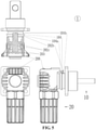
FIG. 1 is an exploded view of a high-voltage connector for energy storage of the present application; -
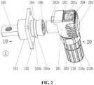
FIG. 2 is a perspective view in a separated state of a high-voltage connector for energy storage of the present application; -
FIG. 3 is a three-plan view and a cross-sectional view in a separated state of the energy storage high-voltage connector of the present application; -
FIG. 4 is a perspective view in a working state of a high-voltage connector for energy storage of the present application; and -
FIG. 5 is a plan three-plan view and a cross-sectional view in a working state of a high-voltage connector for energy storage of the present application. -
name Reference name Reference Connector 1 Pressing boss 202a Socket 10 Buckle 202b Socket body 101 Elastic resetting member 202c Mounting flange 102 Hand-held pluggable portion 203 Electrical isolation groove 103 Hammering boss 204 Fastening ring 104 Hole 205 Annular bevel 104a Crown spring 206 Annular slot 104b Wiring cup opening 207 Pin 105 Locking slider 208 Anti-electric shock cap 106 Waterproof lock washer 209 Plug 20 Protective back cover 210 Plug body 201 Ridge portion 210a Pressing buckle 202 Hexagon portion 210b - To facilitate a better understanding of the present application, a more complete description of the present application is provided below with reference to the drawings.
- It should be noted that when an element is referred to as being "fixed to" another element, it can be directly on the other element or a central element may also be present. When an element is considered to be "connected" to another element, it can be directly connected to the other element or an intermediate element may be present at the same time. The terms "vertical", "horizontal", "left", "right" and similar expressions used herein are for illustrative purposes only, and do not mean that they are the only embodiments.
- Unless otherwise defined, all technical and scientific terms used herein have the same meaning as commonly understood by engineering and technical personnel belonging to the technical field of the application. The terms used in the specification of the application herein are only for describing specific implementations, and are not intended to limit the application. As used herein, the term "and/or" includes any and all combinations of one or more related listed items.
- Please refer to
FIG. 1 andFIG. 2 , a high-voltage connector forenergy storage 1 that also called plug connector, includes asocket 10 and aplug 20. By optimizing thesocket 10 and theplug 20 of theconnector 1, thesocket 10 is inserted to theplug 20 more firmly, and it avoids the looseness between thesocket 10 and theplug 20. - Please refer to
FIG. 1 andFIG. 2 , thesocket 10 includes asocket body 101, a mountingflange 102, anelectrical isolation groove 103, afastening ring 104, apin 105 and ananti-electric shock cap 106. Thepin 105 is a male terminal. - Please refer to
FIG. 1 andFIG 2 , theplug 20 includes aplug body 201, apressing buckle 202, hand-heldpluggable portions 203, a hammeringboss 204, ahole 205, acrown spring 206, awiring cup opening 207, and a lockingslider 208, awaterproof lock washer 209 and aprotective back cover 210. Thehole 205 is a female terminal. - Please refer to
FIG. 2 , thefastening ring 104 of thesocket 10 includes anannular bevel 104a and anannular slot 104b. - Please refer to
FIGS. 1 to 5 , thepressing buckle 202 of theplug 20 includes apressing boss 202a, abuckle 202b, andelastic resetting members 202c. Theelastic resetting members 202c are located on both sides of thepressing buckle 202, and twoelastic resetting members 202c are provided, which are symmetrically arranged in a "Z" shape to the center of pressingbuckle 202. - Please refer to
FIG. 1 , theprotective back cover 210 of theplug 20 includes aridge portion 210a and ahexagonal portion 210b. - Please refer to
FIG. 1 andFIG 2 , thesocket body 101, the mountingflange 102, theelectrical isolation groove 103, thefastening ring 104 and thepin 105 of thesocket 10 are integrally formed, and then assembled with theanti-electric shock cap 106 after being integrally formed. - Please refer to
FIG. 1 andFIG. 2 , theplug body 201, thepressing buckle 202, the hand-heldpluggable portion 203, the hammeringboss 204, thehole 205, thecrown spring 206 and the wiring cup opening 207 of theplug 20 are integrally formed, which, after being integrally formed, are assembled with the lockingslider 208, thewaterproof lock washer 209, and the protectiverear cover 210. - Please refer to
FIGS. 1 to 5 , thepressing buckle 202 and the lockingslider 208 of theplug 20 and thefastening ring 104 of thesocket 10 together form a fastening-locking structure. - Please refer to
FIGS. 1 to 5 , thepressing buckle 202 of theplug 20 is located on theplug body 201. The lockingslider 208 of theplug 20 is slidable in theplug body 201 after the lockingslider 208 is assembled. Thefastening ring 104 of thesocket 10 is located on the outer cylinder of thesocket body 101, and the positions of thefastening ring 104 and theanti-electric shock cap 106 are disposed correspondingly. - Please refer to
FIGS. 1 to 5 , thehole 205 of theplug 20 and thepin 105 of thesocket 10 adopt a cylindrical structure respectively and are respectively provided with a circular cross section. Thepin 105 and thehole 205 form a rotating shaft after thepin 105 is inserted into thehole 205. Theentire plug 20 rotates 360° along the rotating shaft to adjust the outgoing direction of the wire. At the same time, thebuckle 202b of thepressing buckle 202 of theplug 20 rotates along thefastening ring 104 of thesocket 10. - Please refer to
FIG. 1 , theelectrical isolation groove 103 of thesocket 10 is located on the end surface of thesocket body 101, and the positions of theelectrical isolation groove 103 and the reverse of theanti-electric shock cap 106 are disposed correspondingly. Theelectrical isolation groove 103 increases the creepage distance, plays a role of electrical safety, and at the same time makes the appearance of thesocket 10 better. - Please refer to
FIGS. 1 and2 , theanti-electric shock cap 106 of thesocket 10 is installed on the end surface of thepin 105, and the positions of theanti-electric shock cap 106 and thefastening ring 104 are disposed correspondingly. Theanti-electric shock cap 106 is made of an insulating material. Theanti-electric shock cap 106 ensures that thepin 105 of thesocket 10 is not contacted with the charged body, the short circuit between the positive electrode and that of the negative electrode of thepin 105 of thesocket 10 is not caused by charged body between the positive electrode and that of the negative electrode, and the human body is protected from electric shock. - Please refer to
FIGS. 1 to 5 , the hand-heldpluggable portions 203 of theplug 20 are located on two sides of theplug 20, two hand-heldpluggable portions 203 are provided, and one of the two hand-heldpluggable portions 203 is provided on the left side of theplug 20, the other is provided on the right side of theplug 20. The hand-heldpluggable portions 203 increase the force area of hand grip and provide a better force point, which facilitates using fingers to insert and pull theplug 20, rather than relying solely on the friction generated between the fingers and theplug 20 for plugging. Moreover, theplug 20 is more aesthetic. - Please refer to
FIG. 2 andFIG. 4 , the hammeringboss 204 of theplug 20 is located on the end surface of theplug body 201 and the position of the hammeringboss 204 is opposite to thehole 205. The plugging between theplug 20 and thesocket 10 can be performed by hammering, that is, the hammeringboss 204 of theplug 20 is hammered and locked toward thesocket 10 with a blunt tool such as a hammer, so that thehole 205 of theplug 20 can be inserted and buckled to thepin 105 of thesocket 10, and at the same time, thepressing buckle 202 of theplug 20 is locked and buckled to thefastening ring 104 of thesocket 10 through thebuckle 202b. - Please refer to
FIG. 1 , thewaterproof lock washer 209 of theplug 20 is installed in the groove of the outer cylinder between the hand-heldpluggable portions 203 of theplug 20 and the external thread of theplug body 201. Thewaterproof lock washer 209 is waterproof and anti-loosening between theplug body 201 and theprotective back cover 210. - Referring to
FIG. 1 , the interior of thehexagonal part 210b of theprotective back cover 210 of theplug 20 is provided with internal threads, the internal threads of theprotective back cover 210 is threadedly connected with the external threads of theplug body 201, and theprotective back cover 210 is installed and locked to theplug body 201. Theprotective back cover 210 has two fastening methods. The first fastening method is that theridge portion 210a is locked by hand tightening, and the second fastening method is that thehexagonal portion 210b is locked with a wrench or other tools. When theprotective back cover 210 is being locked, the first fastening method, namely, hand-tightening, is preferred, and the second fastening method, namely, tool-fastening is used when the hand-tightening is not too tight. - Referring to
FIG. 1 , theplug 20 is separated from the wire, the cost of the connector is low, the length of the wire is not necessary very accurate, and the after-sales service is more convenient. The wiring cup opening 207 of theplug 20 is used for connecting wires. Firstly, the wire is inserted into theconnection cup opening 207, then the wire production equipment or hydraulic tools are used to press theconnection cup opening 207 into a hexagon, and then theconnection cup opening 207 are wrapped with insulating tape or heat shrinkable tubing to make theconnection cup opening 207 and the wire tightly integrated, that is, theplug 20 and the wire are integrally formed. - Please refer to
FIGS. 1 to 5 , the installation and working principle of the high-voltage connector forenergy storage 1 are introduced by combining the above content: - Firstly, insert the wire into the wiring cup opening 207 of the
plug 20, then use wire production equipment or hydraulic tools to press thewiring cup opening 207 into a hexagon, and then wrap the wiring cup opening with insulating tape or heat shrink tubing to make thewiring cup opening 207 and the wire tightly integrated. - The internal thread of the
protective back cover 210 is screwed with the external thread of theplug body 201 by hand screwing or using tools such as a wrench which enable theprotective back cover 210 to be installed and locked to theplug body 201, so that theprotective back cover 210 of theplug 20 is integrated with the wire. - Firstly, install the
socket 10 to the front panel of the box, and then lock the screws with the four through holes in the mountingflange 102 of thesocket 10. - The locking
slider 208 of theplug 20 is pulled from thesocket 10 toward theplug 20 to slide the lockingslider 208 away from thepressing boss 202a. - The
hole 205 of theplug 20 is inserted into thepin 105 of thesocket 10 and is engaged with thepin 105 of thesocket 10 in an interference fit through thecrown spring 206, which is an electrical connection. - The
pressing buckle 202 of theplug 20 is contacted to theannular bevel 104a of thefastening ring 104 of thesocket 10 through thebuckle 202b, and theannular bevel 104a exerts a force on thebuckle 202b, so that thebuckle 202b rotates toward theplug body 201 with theelastic resetting member 202c as the rotation axis. When thebuckle 202b is snapped into theannular slot 104b of thefastening ring 104, thepressing buckle 202 is restored to its original shape by the elastic deformation of theelastic resetting member 202c. At this time, thebuckle 202b is locked and fastened to thefastening ring 104 to prevent theconnector 1 from loosening. - The locking
slider 208 of theplug 20 is pushed from theplug 20 to thesocket 10, which enables the lockingslider 208 to slide close to thepressing boss 202a. When thepressing boss 202a is accidentally pressed toward the wire, since thepressing boss 202a is blocked and supported by the lockingslider 208, thepressing boss 202a cannot rotate toward the wire with theelastic reset 202c as the rotation axis. On this occasion, the lockingbuckle 202b is fastening buckled and further locking buckled to thefastening ring 104 again to prevent accidental pressing of thepressing boss 202a, and to further prevent theconnector 1 from loosening. - The
pin 105 of thesocket 10 is inserted in to thehole 205 of theplug 20 to form a rotating shaft, and theentire plug 20 and the wire are rotated 360° along the rotating shaft to adjust the outgoing direction of theplug 20. - The locking
slider 208 of theplug 20 is pulled from thesocket 10 toward theplug 20 to enable the lockingslider 208 to slide away from thepressing boss 202a. - Press the
pressing boss 202a of thepressing buckle 202 of theplug 20 toward the wire. Since thepressing boss 202a is not blocked and supported by the lockingslider 208, thepressing boss 202a rotates toward the wire with theelastic reset 202c as the rotation axis. Under the action of the elastic deformation of theelastic reset 202c to thepressing buckle 202, thebuckle 202b rotates toward theplug body 201 with theelastic reset 202c as the rotation axis, and thebuckle 202b is separated from theannular slot 104b. On this occasion, thebuckle 202b is separated from thefastening ring 104. - The
hole 205 of theplug 20 is separated from thepin 105 of thesocket 10 through thecrown spring 206. - Where the plug-in can also be a combination of item 2.2 (Plug-in buckling) and item 2.3 (fastening buckling), that is, the plug-in can be replaced by hammering to plug in. The specific plug-in is to hammer and lock the
hammering boss 204 of theplug 20 toward thesocket 10 with a blunt tool such as a hammer, so that thehole 205 of theplug 20 can be plugged into thepin 105 of thesocket 10 and buckled to thepin 105 of thesocket 10. At the same time, thepressing buckle 202 of theplug 20 is locked and buckled to thefastening ring 104 of thesocket 10 through thebuckle 202b. - Compared with related art, this present application has at least the following advantages:
- By optimizing the
socket 10 and theplug 20, an anti-electric shock high-voltage connector for energy storage is provided, which is provided with a fastening-locking structure, aplug 20 having a hand-held plug-in position structure, capable of rotating 360° to adjust the wire outgoing direction, and separated from the wire. Thesocket 10 is more securely connected to theplug 20 to avoid loosening between thesocket 10 and theplug 20.
Claims (9)
- A high-voltage connector for energy storage, comprising:a socket, wherein the socket comprises a socket body, a mounting flange, an electrical isolation groove, a fastening ring, a pin and an anti-electric shock cap, and the fastening ring of the socket comprises an annular bevel and an annular slot;a plug, wherein the plug comprises a plug body, a pressing buckle, hand-held pluggable portions, a hammering boss, a hole, a crown spring, a wiring cup opening, and a locking slider, a waterproof lock washer and a protective back cover, the pressing buckle of the plug comprises a pressing boss, a buckle, and an elastic resetting member, the protective back cover of the plug comprises a ridge portion and a hexagonal portion;wherein the socket body, the mounting flange, the electrical isolation groove, the fastening ring and the pin of the socket are integrally formed, and after being integrally formed, are assembled with the anti-electric shock cap;wherein the plug body, the pressing buckle, the hand-held pluggable portion, the hammering boss, the hole, the crown spring and the wiring cup opening of the plug are integrally formed, and after being integrally formed, are assembled with the locking slider, the waterproof lock washer, and the protective rear cover;wherein the pressing buckle of the plug, the locking slider, and the fastening ring of the socket together form a fastening-locking structure;wherein the pressing buckle of the plug is located on the plug body, the locking slider of the plug is configured to be slidable in the plug body after being installed, the fastening ring of the socket is located on an outer cylinder of the socket body, and positions of the fastening ring and the anti-electric shock cap are disposed correspondingly.
- The high-voltage connector for energy storage according to claim 1, wherein the hole of the plug and the pin of the socket adopt a cylindrical structure respectively and are respectively provided with a circular cross section.
- The high-voltage connector for energy storage according to claim 1, wherein the electrical isolation groove of the socket is located on an end surface of the socket body, and a position of the electrical isolation groove is opposite to the anti-electric shock cap.
- The high-voltage connector for energy storage according to claim 1, wherein the anti-electric shock cap of the socket is installed on an end surface of the pin, and positions of the anti-electric shock cap and the fastening ring are disposed correspondingly.
- The high-voltage connector for energy storage according to claim 4, wherein the hand-held pluggable portions of the plug are located on two sides of the plug, two hand-held pluggable portions are provided, and one of the two hand-held pluggable portions is located on a left side of the plug, another of the two hand-held pluggable portions is located on a right side of the plug.
- The high-voltage connector for energy storage according to claim 1, wherein the hammering boss of the plug is located on an end surface of the plug body and a position of the hammering boss is opposed to the hole.
- The high-voltage connector for energy storage according to claim 1, wherein the waterproof lock washer of the plug is installed in a groove of the outer cylinder between the hand-held pluggable portions of the plug and external threads of the plug body.
- The high-voltage connector for energy storage according to claim 1, wherein an interior of the hexagonal portion of the protective back cover of the plug is provided with internal threads, and the internal threads of the protective back cover is threadedly connected with external threads of the plug body, and the protective back cover is installed and locked to the plug body.
- The high-voltage connector for energy storage according to claim 1, wherein the plug is separated from a wire, and the wire is inserted into an inside of the wiring cup opening and pressed tightly to enable the plug to be integrated with the wire.
Applications Claiming Priority (2)
| Application Number | Priority Date | Filing Date | Title |
|---|---|---|---|
| CN201910273034.0A CN110112602B (en) | 2019-04-04 | 2019-04-04 | Energy storage high-voltage connector |
| PCT/CN2019/126043 WO2020199653A1 (en) | 2019-04-04 | 2019-12-17 | High-voltage connector for energy storage |
Publications (3)
| Publication Number | Publication Date |
|---|---|
| EP3952028A1 true EP3952028A1 (en) | 2022-02-09 |
| EP3952028A4 EP3952028A4 (en) | 2022-12-28 |
| EP3952028B1 EP3952028B1 (en) | 2025-05-28 |
Family
ID=67485199
Family Applications (1)
| Application Number | Title | Priority Date | Filing Date |
|---|---|---|---|
| EP19922980.8A Active EP3952028B1 (en) | 2019-04-04 | 2019-12-17 | High-voltage connector for energy storage |
Country Status (5)
| Country | Link |
|---|---|
| US (1) | US12155152B2 (en) |
| EP (1) | EP3952028B1 (en) |
| CN (1) | CN110112602B (en) |
| ES (1) | ES3038133T3 (en) |
| WO (1) | WO2020199653A1 (en) |
Cited By (1)
| Publication number | Priority date | Publication date | Assignee | Title |
|---|---|---|---|---|
| EP4445454A1 (en) * | 2021-12-08 | 2024-10-16 | Safran Electrical & Power | Device for electrically joining two sections of electric cable, method for connecting two sections of electric cable by way of such a device, and power cable equipped with such a device |
Families Citing this family (29)
| Publication number | Priority date | Publication date | Assignee | Title |
|---|---|---|---|---|
| CN110112602B (en) | 2019-04-04 | 2021-10-26 | 惠州亿纬锂能股份有限公司 | Energy storage high-voltage connector |
| CN110797709A (en) * | 2019-10-23 | 2020-02-14 | 苏州快可光伏电子股份有限公司 | A push-button high-current high-protection quick-plug connector |
| CN111342301B (en) * | 2020-04-01 | 2024-11-12 | 深圳市安保科技有限公司 | Wiring plug and defibrillator |
| CN111509443B (en) * | 2020-04-30 | 2020-11-03 | 南京盟瑞自动化有限公司 | Canned type high pressure connector convenient to quick installation |
| TWI762347B (en) * | 2021-06-07 | 2022-04-21 | 映興電子股份有限公司 | Butt joint structure of connector |
| CN113346283B (en) * | 2021-06-08 | 2023-02-28 | 太原市月辉新技术产业有限公司 | Charging and discharging device for power box of mining explosion-proof rubber-tyred vehicle |
| CN113471770B (en) * | 2021-08-03 | 2025-05-06 | 广州睿玛科防水电器股份有限公司 | Energy storage connector |
| CN113904177B (en) * | 2021-10-10 | 2022-06-21 | 安徽江淮汽车集团股份有限公司 | Power battery connector protection device |
| CN115021011B (en) * | 2022-03-10 | 2025-02-11 | 深圳巴斯巴科技发展有限公司 | A combined connector |
| CN114899636B (en) | 2022-04-13 | 2024-01-05 | 菲尼克斯亚太电气(南京)有限公司 | Connector assembly suitable for energy storage system |
| CN114725752B (en) * | 2022-04-22 | 2023-11-21 | 深圳市展荣鑫精密技术有限公司 | crown spring machine |
| CN115429421A (en) * | 2022-09-15 | 2022-12-06 | 海泽临床成果转化医学研究院(无锡)有限公司 | Electric coagulation knife structure |
| CN115764418B (en) * | 2022-10-12 | 2025-08-12 | 宁波冠泰电子有限公司 | Waterproof construction plug-in binding post |
| TWI818772B (en) * | 2022-10-18 | 2023-10-11 | 佳必琪國際股份有限公司 | Power storage connector |
| CN115513723B (en) * | 2022-11-01 | 2023-07-14 | 江西航同电气科技有限公司 | Energy storage connector locking structure |
| CN115566461A (en) * | 2022-11-09 | 2023-01-03 | 苏州谐通光伏科技股份有限公司 | Energy storage connector with good plugging stability |
| CN116053847A (en) * | 2023-03-10 | 2023-05-02 | 菲尼克斯亚太电气(南京)有限公司 | A plug and connector |
| CN116581604A (en) * | 2023-05-06 | 2023-08-11 | 町洋机电(中国)有限公司 | quick plug connector |
| CN116259994B (en) * | 2023-05-16 | 2023-07-25 | 深圳市天麟精密模具有限公司 | Network communication connector |
| CN116914500B (en) * | 2023-08-11 | 2024-08-09 | 东莞市江涵电子有限公司 | A quick-plug energy storage connector |
| CN116799539B (en) * | 2023-08-16 | 2023-10-27 | 深圳欧晟科连接技术有限公司 | Crown spring capable of reducing insertion force of docking plug |
| CN116780261B (en) * | 2023-08-24 | 2023-11-03 | 河南省杰恩特科技有限公司 | Energy storage connector |
| CN117543278B (en) * | 2023-10-19 | 2024-12-03 | 金锚电力控股有限公司 | Heavy-current waterproof energy storage connector |
| CN119050713B (en) * | 2023-12-21 | 2025-08-22 | 菲尼克斯亚太电气(南京)有限公司 | Connector socket assembly and energy storage connector |
| CN118281636A (en) * | 2024-04-01 | 2024-07-02 | 深圳市亿能科技有限公司 | A high current waterproof energy storage connector with secondary lock |
| CN118431821B (en) * | 2024-07-05 | 2024-08-27 | 湖南蠡庄智能科技有限公司 | Module connection copper bar and copper bar quick plug |
| CN119651262B (en) * | 2024-12-05 | 2025-09-09 | 深圳市泽旺精密电子有限公司 | Formula energy storage connecting terminal is inhaled to magnetism |
| TWI908554B (en) * | 2024-12-20 | 2025-12-11 | 進聯工業股份有限公司 | Linkage structure of energy storage connector |
| USD1125071S1 (en) | 2025-03-26 | 2026-05-05 | Molex, Llc | Connector |
Family Cites Families (39)
| Publication number | Priority date | Publication date | Assignee | Title |
|---|---|---|---|---|
| US5433623A (en) * | 1993-04-19 | 1995-07-18 | Sumitomo Wiring Systems, Ltd. | Coupling device of charging connector assembly for electric car |
| JP3253054B2 (en) * | 1996-04-11 | 2002-02-04 | 矢崎総業株式会社 | Connection terminals and connectors |
| US5913691A (en) * | 1996-08-20 | 1999-06-22 | Chrysler Corporation | Dual power/control connector |
| US5934938A (en) * | 1996-08-20 | 1999-08-10 | Chrysler Corporation | Split seal retainer for an electrical connector |
| US5820409A (en) * | 1996-08-20 | 1998-10-13 | Chrysler Corporation | Rotatable pin connector |
| US6213799B1 (en) * | 1998-05-27 | 2001-04-10 | Hubbell Incorporated | Anti-flashover ring for a bushing insert |
| US6453776B1 (en) * | 2001-03-14 | 2002-09-24 | Saskatchewan Power Corporation | Separable loadbreak connector flashover inhibiting cuff venting tool |
| CN2753002Y (en) * | 2004-10-14 | 2006-01-18 | 上海环达计算机科技有限公司 | Electric connector |
| US7341468B2 (en) * | 2005-07-29 | 2008-03-11 | Cooper Technologies Company | Separable loadbreak connector and system with shock absorbent fault closure stop |
| US7316584B2 (en) * | 2005-09-13 | 2008-01-08 | Deutsch Engineered Connecting Devices, Inc. | Matched impedance shielded pair interconnection system for high reliability applications |
| EP2130270A1 (en) * | 2007-03-27 | 2009-12-09 | Van-System s.r.l | Electrical connector |
| CN201210555Y (en) * | 2008-06-06 | 2009-03-18 | 纬创资通股份有限公司 | Easy-to-pull plug |
| US8192212B2 (en) * | 2008-08-04 | 2012-06-05 | Fci Automotive Holding | Electrical connector system with temporarily blocking during unmating of two connectors |
| JP5123144B2 (en) * | 2008-11-21 | 2013-01-16 | 矢崎総業株式会社 | Charging connector |
| DE102010014981A1 (en) * | 2010-04-14 | 2011-10-20 | Pfisterer Kontaktsysteme Gmbh | Device for electrically connecting a cable, in particular plug connection part |
| JP5373757B2 (en) * | 2010-12-22 | 2013-12-18 | 日本航空電子工業株式会社 | connector |
| JP2012139040A (en) | 2010-12-27 | 2012-07-19 | Hitachi Cable Ltd | Housing with flange |
| CN202276016U (en) * | 2011-09-28 | 2012-06-13 | 无锡艾德里安科技有限公司 | Plug with switch |
| CN202395236U (en) * | 2012-01-18 | 2012-08-22 | 中国矿业大学 | Easily-pulled plug |
| DE102012201123B3 (en) * | 2012-01-26 | 2013-03-21 | Lisa Dräxlmaier GmbH | Angled high-voltage plug |
| CN103078211B (en) * | 2013-02-17 | 2014-12-10 | 安费诺-泰姆斯(常州)通讯设备有限公司 | Right-angle type electric connector |
| CN203660175U (en) * | 2013-11-21 | 2014-06-18 | 江苏通领科技有限公司 | Seal type plug |
| US8968021B1 (en) * | 2013-12-11 | 2015-03-03 | JAE Oregon, Inc. | Self-rejecting automotive harness connector |
| CN104917018B (en) * | 2015-05-20 | 2017-10-20 | 莫西元 | A kind of optional high-voltage great-current connector in direction |
| WO2017079336A1 (en) * | 2015-11-02 | 2017-05-11 | Simmonds Simon | Female cabling connector |
| CN108475889B (en) * | 2016-01-13 | 2020-07-03 | 莫列斯有限公司 | High-power electric connector |
| CN205488768U (en) * | 2016-02-26 | 2016-08-17 | 刘冬 | Rotatory high -pressure corner joint ware of electric automobile 360 |
| CN105576434B (en) * | 2016-02-26 | 2024-03-12 | 刘冬 | A 360° rotating high-voltage elbow connector for electric vehicles |
| CN106450939B (en) * | 2016-10-31 | 2019-12-03 | 河南天海电器有限公司 | A kind of high-tension shielding connector assembly |
| CN206195068U (en) * | 2016-11-07 | 2017-05-24 | 东莞市伊克斯康电子科技有限公司 | High current self-locking connector |
| CN206271942U (en) * | 2016-12-23 | 2017-06-20 | 佛山市思特传导科技有限公司 | One kind plugs easily plug |
| CN108173083A (en) * | 2018-01-21 | 2018-06-15 | 顺科新能源技术股份有限公司 | A high-voltage energy storage quick-plug connector |
| CN108232704A (en) * | 2018-02-25 | 2018-06-29 | 苏州快可光伏电子股份有限公司 | A kind of high current height for energy-storage system protects connection system |
| CN208173900U (en) * | 2018-06-12 | 2018-11-30 | 新乡晨风绿能电气技术有限公司 | A kind of high-voltage great-current connector |
| CN208336664U (en) * | 2018-07-17 | 2019-01-04 | 深圳市大塑实业有限公司 | Electric connector |
| CN109301618A (en) * | 2018-09-17 | 2019-02-01 | 合肥晓拂新能源有限公司 | A kind of elbow energy storage connector |
| CN109193269A (en) * | 2018-09-17 | 2019-01-11 | 合肥晓拂新能源有限公司 | A kind of energy storage connector |
| CN109473816A (en) * | 2018-10-15 | 2019-03-15 | 常州诺德电子有限公司 | New energy vehicle connector |
| CN110112602B (en) * | 2019-04-04 | 2021-10-26 | 惠州亿纬锂能股份有限公司 | Energy storage high-voltage connector |
-
2019
- 2019-04-04 CN CN201910273034.0A patent/CN110112602B/en active Active
- 2019-12-17 US US17/601,361 patent/US12155152B2/en active Active
- 2019-12-17 WO PCT/CN2019/126043 patent/WO2020199653A1/en not_active Ceased
- 2019-12-17 ES ES19922980T patent/ES3038133T3/en active Active
- 2019-12-17 EP EP19922980.8A patent/EP3952028B1/en active Active
Cited By (1)
| Publication number | Priority date | Publication date | Assignee | Title |
|---|---|---|---|---|
| EP4445454A1 (en) * | 2021-12-08 | 2024-10-16 | Safran Electrical & Power | Device for electrically joining two sections of electric cable, method for connecting two sections of electric cable by way of such a device, and power cable equipped with such a device |
Also Published As
| Publication number | Publication date |
|---|---|
| EP3952028B1 (en) | 2025-05-28 |
| WO2020199653A1 (en) | 2020-10-08 |
| US20220336997A1 (en) | 2022-10-20 |
| US12155152B2 (en) | 2024-11-26 |
| ES3038133T3 (en) | 2025-10-09 |
| EP3952028A4 (en) | 2022-12-28 |
| CN110112602A (en) | 2019-08-09 |
| CN110112602B (en) | 2021-10-26 |
Similar Documents
| Publication | Publication Date | Title |
|---|---|---|
| US12155152B2 (en) | High-voltage connector for energy storage | |
| US10749298B2 (en) | Plug retention system | |
| US9293858B2 (en) | Screw down connector | |
| US6979205B2 (en) | Modular signal and power connection device | |
| US5238424A (en) | In-line extension cord | |
| US6688894B2 (en) | Umbilical cable assembly | |
| US9634429B2 (en) | Connector for a power input | |
| US9698516B2 (en) | Connector | |
| WO2011160538A1 (en) | Plug as well as socket of coaxial connector and coaxial connector | |
| CN109742577A (en) | A kind of resilient socket component | |
| WO2001037400A3 (en) | Electric device grounding system | |
| CN209516094U (en) | Resilient socket component | |
| EP1703595B1 (en) | Electric plug connector and method for producing an electric plug connector | |
| US10116068B1 (en) | Bonding block with rotatable compression ground contact | |
| US20230124123A1 (en) | Appliance power connector | |
| CN216981061U (en) | Three-way aviation plug and engineering equipment | |
| KR200309939Y1 (en) | Connector device for electrical connection | |
| CN117543240A (en) | Terminal assembly, connector and application | |
| CN201994460U (en) | Grounded and telescopic industrial electric coupler, plug and socket thereof | |
| CN212136572U (en) | High Voltage Connectors and Battery Packs | |
| CN220156156U (en) | Surgical robot strain elimination box | |
| CN219067367U (en) | Self-locking cable connector assembly | |
| CN219843231U (en) | Anti-drop structure of locking wire mechanism for industrial connector | |
| CN221126419U (en) | TV/PAL connector and functional device with same | |
| CN222775666U (en) | Single-core heavy-current through-wall connector with self-locking and waterproof functions |
Legal Events
| Date | Code | Title | Description |
|---|---|---|---|
| STAA | Information on the status of an ep patent application or granted ep patent |
Free format text: STATUS: THE INTERNATIONAL PUBLICATION HAS BEEN MADE |
|
| PUAI | Public reference made under article 153(3) epc to a published international application that has entered the european phase |
Free format text: ORIGINAL CODE: 0009012 |
|
| STAA | Information on the status of an ep patent application or granted ep patent |
Free format text: STATUS: REQUEST FOR EXAMINATION WAS MADE |
|
| 17P | Request for examination filed |
Effective date: 20211104 |
|
| AK | Designated contracting states |
Kind code of ref document: A1 Designated state(s): AL AT BE BG CH CY CZ DE DK EE ES FI FR GB GR HR HU IE IS IT LI LT LU LV MC MK MT NL NO PL PT RO RS SE SI SK SM TR |
|
| DAV | Request for validation of the european patent (deleted) | ||
| DAX | Request for extension of the european patent (deleted) | ||
| A4 | Supplementary search report drawn up and despatched |
Effective date: 20221124 |
|
| RIC1 | Information provided on ipc code assigned before grant |
Ipc: H01R 101/00 20060101ALN20221118BHEP Ipc: H01R 13/639 20060101ALN20221118BHEP Ipc: H01R 13/627 20060101ALI20221118BHEP Ipc: H01R 13/52 20060101ALI20221118BHEP Ipc: H01R 13/187 20060101ALI20221118BHEP Ipc: H01R 13/44 20060101AFI20221118BHEP |
|
| REG | Reference to a national code |
Ref country code: DE Ref legal event code: R079 Free format text: PREVIOUS MAIN CLASS: H01R0013447000 Ipc: H01R0013440000 Ref document number: 602019070646 Country of ref document: DE |
|
| GRAP | Despatch of communication of intention to grant a patent |
Free format text: ORIGINAL CODE: EPIDOSNIGR1 |
|
| STAA | Information on the status of an ep patent application or granted ep patent |
Free format text: STATUS: GRANT OF PATENT IS INTENDED |
|
| RIC1 | Information provided on ipc code assigned before grant |
Ipc: H01R 101/00 20060101ALN20241212BHEP Ipc: H01R 13/639 20060101ALN20241212BHEP Ipc: H01R 13/627 20060101ALI20241212BHEP Ipc: H01R 13/52 20060101ALI20241212BHEP Ipc: H01R 13/187 20060101ALI20241212BHEP Ipc: H01R 13/44 20060101AFI20241212BHEP |
|
| INTG | Intention to grant announced |
Effective date: 20241223 |
|
| GRAS | Grant fee paid |
Free format text: ORIGINAL CODE: EPIDOSNIGR3 |
|
| GRAA | (expected) grant |
Free format text: ORIGINAL CODE: 0009210 |
|
| STAA | Information on the status of an ep patent application or granted ep patent |
Free format text: STATUS: THE PATENT HAS BEEN GRANTED |
|
| AK | Designated contracting states |
Kind code of ref document: B1 Designated state(s): AL AT BE BG CH CY CZ DE DK EE ES FI FR GB GR HR HU IE IS IT LI LT LU LV MC MK MT NL NO PL PT RO RS SE SI SK SM TR |
|
| REG | Reference to a national code |
Ref country code: GB Ref legal event code: FG4D |
|
| REG | Reference to a national code |
Ref country code: CH Ref legal event code: EP |
|
| REG | Reference to a national code |
Ref country code: IE Ref legal event code: FG4D Ref country code: DE Ref legal event code: R096 Ref document number: 602019070646 Country of ref document: DE |
|
| REG | Reference to a national code |
Ref country code: NL Ref legal event code: FP |
|
| REG | Reference to a national code |
Ref country code: SE Ref legal event code: TRGR |
|
| PG25 | Lapsed in a contracting state [announced via postgrant information from national office to epo] |
Ref country code: FI Free format text: LAPSE BECAUSE OF FAILURE TO SUBMIT A TRANSLATION OF THE DESCRIPTION OR TO PAY THE FEE WITHIN THE PRESCRIBED TIME-LIMIT Effective date: 20250528 |
|
| REG | Reference to a national code |
Ref country code: ES Ref legal event code: FG2A Ref document number: 3038133 Country of ref document: ES Kind code of ref document: T3 Effective date: 20251009 |
|
| REG | Reference to a national code |
Ref country code: LT Ref legal event code: MG9D |
|
| PG25 | Lapsed in a contracting state [announced via postgrant information from national office to epo] |
Ref country code: NO Free format text: LAPSE BECAUSE OF FAILURE TO SUBMIT A TRANSLATION OF THE DESCRIPTION OR TO PAY THE FEE WITHIN THE PRESCRIBED TIME-LIMIT Effective date: 20250828 Ref country code: GR Free format text: LAPSE BECAUSE OF FAILURE TO SUBMIT A TRANSLATION OF THE DESCRIPTION OR TO PAY THE FEE WITHIN THE PRESCRIBED TIME-LIMIT Effective date: 20250829 |
|
| PG25 | Lapsed in a contracting state [announced via postgrant information from national office to epo] |
Ref country code: PL Free format text: LAPSE BECAUSE OF FAILURE TO SUBMIT A TRANSLATION OF THE DESCRIPTION OR TO PAY THE FEE WITHIN THE PRESCRIBED TIME-LIMIT Effective date: 20250528 |
|
| PG25 | Lapsed in a contracting state [announced via postgrant information from national office to epo] |
Ref country code: BG Free format text: LAPSE BECAUSE OF FAILURE TO SUBMIT A TRANSLATION OF THE DESCRIPTION OR TO PAY THE FEE WITHIN THE PRESCRIBED TIME-LIMIT Effective date: 20250528 |
|
| PG25 | Lapsed in a contracting state [announced via postgrant information from national office to epo] |
Ref country code: HR Free format text: LAPSE BECAUSE OF FAILURE TO SUBMIT A TRANSLATION OF THE DESCRIPTION OR TO PAY THE FEE WITHIN THE PRESCRIBED TIME-LIMIT Effective date: 20250528 |
|
| PG25 | Lapsed in a contracting state [announced via postgrant information from national office to epo] |
Ref country code: RS Free format text: LAPSE BECAUSE OF FAILURE TO SUBMIT A TRANSLATION OF THE DESCRIPTION OR TO PAY THE FEE WITHIN THE PRESCRIBED TIME-LIMIT Effective date: 20250828 |
|
| PG25 | Lapsed in a contracting state [announced via postgrant information from national office to epo] |
Ref country code: IS Free format text: LAPSE BECAUSE OF FAILURE TO SUBMIT A TRANSLATION OF THE DESCRIPTION OR TO PAY THE FEE WITHIN THE PRESCRIBED TIME-LIMIT Effective date: 20250928 |
|
| PG25 | Lapsed in a contracting state [announced via postgrant information from national office to epo] |
Ref country code: LV Free format text: LAPSE BECAUSE OF FAILURE TO SUBMIT A TRANSLATION OF THE DESCRIPTION OR TO PAY THE FEE WITHIN THE PRESCRIBED TIME-LIMIT Effective date: 20250528 |
|
| PGFP | Annual fee paid to national office [announced via postgrant information from national office to epo] |
Ref country code: NL Payment date: 20251024 Year of fee payment: 7 |
|
| REG | Reference to a national code |
Ref country code: AT Ref legal event code: MK05 Ref document number: 1799211 Country of ref document: AT Kind code of ref document: T Effective date: 20250528 |
|
| PGFP | Annual fee paid to national office [announced via postgrant information from national office to epo] |
Ref country code: DE Payment date: 20251022 Year of fee payment: 7 |
|
| PGFP | Annual fee paid to national office [announced via postgrant information from national office to epo] |
Ref country code: GB Payment date: 20251023 Year of fee payment: 7 |
|
| PG25 | Lapsed in a contracting state [announced via postgrant information from national office to epo] |
Ref country code: SM Free format text: LAPSE BECAUSE OF FAILURE TO SUBMIT A TRANSLATION OF THE DESCRIPTION OR TO PAY THE FEE WITHIN THE PRESCRIBED TIME-LIMIT Effective date: 20250528 Ref country code: DK Free format text: LAPSE BECAUSE OF FAILURE TO SUBMIT A TRANSLATION OF THE DESCRIPTION OR TO PAY THE FEE WITHIN THE PRESCRIBED TIME-LIMIT Effective date: 20250528 Ref country code: AT Free format text: LAPSE BECAUSE OF FAILURE TO SUBMIT A TRANSLATION OF THE DESCRIPTION OR TO PAY THE FEE WITHIN THE PRESCRIBED TIME-LIMIT Effective date: 20250528 |
|
| PGFP | Annual fee paid to national office [announced via postgrant information from national office to epo] |
Ref country code: SE Payment date: 20251028 Year of fee payment: 7 |
|
| PG25 | Lapsed in a contracting state [announced via postgrant information from national office to epo] |
Ref country code: CZ Free format text: LAPSE BECAUSE OF FAILURE TO SUBMIT A TRANSLATION OF THE DESCRIPTION OR TO PAY THE FEE WITHIN THE PRESCRIBED TIME-LIMIT Effective date: 20250528 |
|
| PG25 | Lapsed in a contracting state [announced via postgrant information from national office to epo] |
Ref country code: EE Free format text: LAPSE BECAUSE OF FAILURE TO SUBMIT A TRANSLATION OF THE DESCRIPTION OR TO PAY THE FEE WITHIN THE PRESCRIBED TIME-LIMIT Effective date: 20250528 |
|
| PG25 | Lapsed in a contracting state [announced via postgrant information from national office to epo] |
Ref country code: SK Free format text: LAPSE BECAUSE OF FAILURE TO SUBMIT A TRANSLATION OF THE DESCRIPTION OR TO PAY THE FEE WITHIN THE PRESCRIBED TIME-LIMIT Effective date: 20250528 Ref country code: RO Free format text: LAPSE BECAUSE OF FAILURE TO SUBMIT A TRANSLATION OF THE DESCRIPTION OR TO PAY THE FEE WITHIN THE PRESCRIBED TIME-LIMIT Effective date: 20250528 |
|
| PG25 | Lapsed in a contracting state [announced via postgrant information from national office to epo] |
Ref country code: IT Free format text: LAPSE BECAUSE OF FAILURE TO SUBMIT A TRANSLATION OF THE DESCRIPTION OR TO PAY THE FEE WITHIN THE PRESCRIBED TIME-LIMIT Effective date: 20250528 |
|
| REG | Reference to a national code |
Ref country code: DE Ref legal event code: R097 Ref document number: 602019070646 Country of ref document: DE |
|
| PLBE | No opposition filed within time limit |
Free format text: ORIGINAL CODE: 0009261 |
|
| STAA | Information on the status of an ep patent application or granted ep patent |
Free format text: STATUS: NO OPPOSITION FILED WITHIN TIME LIMIT |
|
| REG | Reference to a national code |
Ref country code: CH Ref legal event code: L10 Free format text: ST27 STATUS EVENT CODE: U-0-0-L10-L00 (AS PROVIDED BY THE NATIONAL OFFICE) Effective date: 20260409 |
|
| PGFP | Annual fee paid to national office [announced via postgrant information from national office to epo] |
Ref country code: ES Payment date: 20260112 Year of fee payment: 7 |
|
| 26N | No opposition filed |
Effective date: 20260303 |