EP3952005A1 - Battery module and battery pack including same - Google Patents
Battery module and battery pack including same Download PDFInfo
- Publication number
- EP3952005A1 EP3952005A1 EP20873701.5A EP20873701A EP3952005A1 EP 3952005 A1 EP3952005 A1 EP 3952005A1 EP 20873701 A EP20873701 A EP 20873701A EP 3952005 A1 EP3952005 A1 EP 3952005A1
- Authority
- EP
- European Patent Office
- Prior art keywords
- battery cells
- stack
- battery
- battery module
- end plate
- Prior art date
- Legal status (The legal status is an assumption and is not a legal conclusion. Google has not performed a legal analysis and makes no representation as to the accuracy of the status listed.)
- Pending
Links
Images



Classifications
-
- H—ELECTRICITY
- H01—ELECTRIC ELEMENTS
- H01M—PROCESSES OR MEANS, e.g. BATTERIES, FOR THE DIRECT CONVERSION OF CHEMICAL ENERGY INTO ELECTRICAL ENERGY
- H01M50/00—Constructional details or processes of manufacture of the non-active parts of electrochemical cells other than fuel cells, e.g. hybrid cells
- H01M50/20—Mountings; Secondary casings or frames; Racks, modules or packs; Suspension devices; Shock absorbers; Transport or carrying devices; Holders
- H01M50/204—Racks, modules or packs for multiple batteries or multiple cells
- H01M50/207—Racks, modules or packs for multiple batteries or multiple cells characterised by their shape
- H01M50/209—Racks, modules or packs for multiple batteries or multiple cells characterised by their shape adapted for prismatic or rectangular cells
-
- H—ELECTRICITY
- H01—ELECTRIC ELEMENTS
- H01M—PROCESSES OR MEANS, e.g. BATTERIES, FOR THE DIRECT CONVERSION OF CHEMICAL ENERGY INTO ELECTRICAL ENERGY
- H01M50/00—Constructional details or processes of manufacture of the non-active parts of electrochemical cells other than fuel cells, e.g. hybrid cells
- H01M50/20—Mountings; Secondary casings or frames; Racks, modules or packs; Suspension devices; Shock absorbers; Transport or carrying devices; Holders
-
- H—ELECTRICITY
- H01—ELECTRIC ELEMENTS
- H01M—PROCESSES OR MEANS, e.g. BATTERIES, FOR THE DIRECT CONVERSION OF CHEMICAL ENERGY INTO ELECTRICAL ENERGY
- H01M10/00—Secondary cells; Manufacture thereof
- H01M10/42—Methods or arrangements for servicing or maintenance of secondary cells or secondary half-cells
- H01M10/48—Accumulators combined with arrangements for measuring, testing or indicating the condition of cells, e.g. the level or density of the electrolyte
-
- H—ELECTRICITY
- H01—ELECTRIC ELEMENTS
- H01M—PROCESSES OR MEANS, e.g. BATTERIES, FOR THE DIRECT CONVERSION OF CHEMICAL ENERGY INTO ELECTRICAL ENERGY
- H01M10/00—Secondary cells; Manufacture thereof
- H01M10/60—Heating or cooling; Temperature control
- H01M10/61—Types of temperature control
- H01M10/613—Cooling or keeping cold
-
- H—ELECTRICITY
- H01—ELECTRIC ELEMENTS
- H01M—PROCESSES OR MEANS, e.g. BATTERIES, FOR THE DIRECT CONVERSION OF CHEMICAL ENERGY INTO ELECTRICAL ENERGY
- H01M10/00—Secondary cells; Manufacture thereof
- H01M10/60—Heating or cooling; Temperature control
- H01M10/65—Means for temperature control structurally associated with the cells
- H01M10/653—Means for temperature control structurally associated with the cells characterised by electrically insulating or thermally conductive materials
-
- H—ELECTRICITY
- H01—ELECTRIC ELEMENTS
- H01M—PROCESSES OR MEANS, e.g. BATTERIES, FOR THE DIRECT CONVERSION OF CHEMICAL ENERGY INTO ELECTRICAL ENERGY
- H01M10/00—Secondary cells; Manufacture thereof
- H01M10/60—Heating or cooling; Temperature control
- H01M10/65—Means for temperature control structurally associated with the cells
- H01M10/655—Solid structures for heat exchange or heat conduction
- H01M10/6551—Surfaces specially adapted for heat dissipation or radiation, e.g. fins or coatings
-
- H—ELECTRICITY
- H01—ELECTRIC ELEMENTS
- H01M—PROCESSES OR MEANS, e.g. BATTERIES, FOR THE DIRECT CONVERSION OF CHEMICAL ENERGY INTO ELECTRICAL ENERGY
- H01M10/00—Secondary cells; Manufacture thereof
- H01M10/60—Heating or cooling; Temperature control
- H01M10/65—Means for temperature control structurally associated with the cells
- H01M10/655—Solid structures for heat exchange or heat conduction
- H01M10/6556—Solid parts with flow channel passages or pipes for heat exchange
-
- H—ELECTRICITY
- H01—ELECTRIC ELEMENTS
- H01M—PROCESSES OR MEANS, e.g. BATTERIES, FOR THE DIRECT CONVERSION OF CHEMICAL ENERGY INTO ELECTRICAL ENERGY
- H01M50/00—Constructional details or processes of manufacture of the non-active parts of electrochemical cells other than fuel cells, e.g. hybrid cells
- H01M50/20—Mountings; Secondary casings or frames; Racks, modules or packs; Suspension devices; Shock absorbers; Transport or carrying devices; Holders
- H01M50/204—Racks, modules or packs for multiple batteries or multiple cells
- H01M50/207—Racks, modules or packs for multiple batteries or multiple cells characterised by their shape
- H01M50/211—Racks, modules or packs for multiple batteries or multiple cells characterised by their shape adapted for pouch cells
-
- H—ELECTRICITY
- H01—ELECTRIC ELEMENTS
- H01M—PROCESSES OR MEANS, e.g. BATTERIES, FOR THE DIRECT CONVERSION OF CHEMICAL ENERGY INTO ELECTRICAL ENERGY
- H01M50/00—Constructional details or processes of manufacture of the non-active parts of electrochemical cells other than fuel cells, e.g. hybrid cells
- H01M50/20—Mountings; Secondary casings or frames; Racks, modules or packs; Suspension devices; Shock absorbers; Transport or carrying devices; Holders
- H01M50/218—Mountings; Secondary casings or frames; Racks, modules or packs; Suspension devices; Shock absorbers; Transport or carrying devices; Holders characterised by the material
- H01M50/22—Mountings; Secondary casings or frames; Racks, modules or packs; Suspension devices; Shock absorbers; Transport or carrying devices; Holders characterised by the material of the casings or racks
- H01M50/222—Inorganic material
- H01M50/224—Metals
-
- H—ELECTRICITY
- H01—ELECTRIC ELEMENTS
- H01M—PROCESSES OR MEANS, e.g. BATTERIES, FOR THE DIRECT CONVERSION OF CHEMICAL ENERGY INTO ELECTRICAL ENERGY
- H01M50/00—Constructional details or processes of manufacture of the non-active parts of electrochemical cells other than fuel cells, e.g. hybrid cells
- H01M50/20—Mountings; Secondary casings or frames; Racks, modules or packs; Suspension devices; Shock absorbers; Transport or carrying devices; Holders
- H01M50/218—Mountings; Secondary casings or frames; Racks, modules or packs; Suspension devices; Shock absorbers; Transport or carrying devices; Holders characterised by the material
- H01M50/22—Mountings; Secondary casings or frames; Racks, modules or packs; Suspension devices; Shock absorbers; Transport or carrying devices; Holders characterised by the material of the casings or racks
- H01M50/227—Organic material
-
- H—ELECTRICITY
- H01—ELECTRIC ELEMENTS
- H01M—PROCESSES OR MEANS, e.g. BATTERIES, FOR THE DIRECT CONVERSION OF CHEMICAL ENERGY INTO ELECTRICAL ENERGY
- H01M50/00—Constructional details or processes of manufacture of the non-active parts of electrochemical cells other than fuel cells, e.g. hybrid cells
- H01M50/20—Mountings; Secondary casings or frames; Racks, modules or packs; Suspension devices; Shock absorbers; Transport or carrying devices; Holders
- H01M50/233—Mountings; Secondary casings or frames; Racks, modules or packs; Suspension devices; Shock absorbers; Transport or carrying devices; Holders characterised by physical properties of casings or racks, e.g. dimensions
-
- H—ELECTRICITY
- H01—ELECTRIC ELEMENTS
- H01M—PROCESSES OR MEANS, e.g. BATTERIES, FOR THE DIRECT CONVERSION OF CHEMICAL ENERGY INTO ELECTRICAL ENERGY
- H01M50/00—Constructional details or processes of manufacture of the non-active parts of electrochemical cells other than fuel cells, e.g. hybrid cells
- H01M50/20—Mountings; Secondary casings or frames; Racks, modules or packs; Suspension devices; Shock absorbers; Transport or carrying devices; Holders
- H01M50/233—Mountings; Secondary casings or frames; Racks, modules or packs; Suspension devices; Shock absorbers; Transport or carrying devices; Holders characterised by physical properties of casings or racks, e.g. dimensions
- H01M50/24—Mountings; Secondary casings or frames; Racks, modules or packs; Suspension devices; Shock absorbers; Transport or carrying devices; Holders characterised by physical properties of casings or racks, e.g. dimensions adapted for protecting batteries from their environment, e.g. from corrosion
-
- H—ELECTRICITY
- H01—ELECTRIC ELEMENTS
- H01M—PROCESSES OR MEANS, e.g. BATTERIES, FOR THE DIRECT CONVERSION OF CHEMICAL ENERGY INTO ELECTRICAL ENERGY
- H01M50/00—Constructional details or processes of manufacture of the non-active parts of electrochemical cells other than fuel cells, e.g. hybrid cells
- H01M50/20—Mountings; Secondary casings or frames; Racks, modules or packs; Suspension devices; Shock absorbers; Transport or carrying devices; Holders
- H01M50/244—Secondary casings; Racks; Suspension devices; Carrying devices; Holders characterised by their mounting method
-
- H—ELECTRICITY
- H01—ELECTRIC ELEMENTS
- H01M—PROCESSES OR MEANS, e.g. BATTERIES, FOR THE DIRECT CONVERSION OF CHEMICAL ENERGY INTO ELECTRICAL ENERGY
- H01M50/00—Constructional details or processes of manufacture of the non-active parts of electrochemical cells other than fuel cells, e.g. hybrid cells
- H01M50/20—Mountings; Secondary casings or frames; Racks, modules or packs; Suspension devices; Shock absorbers; Transport or carrying devices; Holders
- H01M50/258—Modular batteries; Casings provided with means for assembling
-
- H—ELECTRICITY
- H01—ELECTRIC ELEMENTS
- H01M—PROCESSES OR MEANS, e.g. BATTERIES, FOR THE DIRECT CONVERSION OF CHEMICAL ENERGY INTO ELECTRICAL ENERGY
- H01M50/00—Constructional details or processes of manufacture of the non-active parts of electrochemical cells other than fuel cells, e.g. hybrid cells
- H01M50/20—Mountings; Secondary casings or frames; Racks, modules or packs; Suspension devices; Shock absorbers; Transport or carrying devices; Holders
- H01M50/262—Mountings; Secondary casings or frames; Racks, modules or packs; Suspension devices; Shock absorbers; Transport or carrying devices; Holders with fastening means, e.g. locks
- H01M50/264—Mountings; Secondary casings or frames; Racks, modules or packs; Suspension devices; Shock absorbers; Transport or carrying devices; Holders with fastening means, e.g. locks for cells or batteries, e.g. straps, tie rods or peripheral frames
-
- H—ELECTRICITY
- H01—ELECTRIC ELEMENTS
- H01M—PROCESSES OR MEANS, e.g. BATTERIES, FOR THE DIRECT CONVERSION OF CHEMICAL ENERGY INTO ELECTRICAL ENERGY
- H01M50/00—Constructional details or processes of manufacture of the non-active parts of electrochemical cells other than fuel cells, e.g. hybrid cells
- H01M50/20—Mountings; Secondary casings or frames; Racks, modules or packs; Suspension devices; Shock absorbers; Transport or carrying devices; Holders
- H01M50/271—Lids or covers for the racks or secondary casings
- H01M50/273—Lids or covers for the racks or secondary casings characterised by the material
- H01M50/278—Organic material
-
- H—ELECTRICITY
- H01—ELECTRIC ELEMENTS
- H01M—PROCESSES OR MEANS, e.g. BATTERIES, FOR THE DIRECT CONVERSION OF CHEMICAL ENERGY INTO ELECTRICAL ENERGY
- H01M50/00—Constructional details or processes of manufacture of the non-active parts of electrochemical cells other than fuel cells, e.g. hybrid cells
- H01M50/50—Current conducting connections for cells or batteries
- H01M50/502—Interconnectors for connecting terminals of adjacent batteries; Interconnectors for connecting cells outside a battery casing
- H01M50/507—Interconnectors for connecting terminals of adjacent batteries; Interconnectors for connecting cells outside a battery casing comprising an arrangement of two or more busbars within a container structure, e.g. busbar modules
-
- H—ELECTRICITY
- H01—ELECTRIC ELEMENTS
- H01M—PROCESSES OR MEANS, e.g. BATTERIES, FOR THE DIRECT CONVERSION OF CHEMICAL ENERGY INTO ELECTRICAL ENERGY
- H01M50/00—Constructional details or processes of manufacture of the non-active parts of electrochemical cells other than fuel cells, e.g. hybrid cells
- H01M50/50—Current conducting connections for cells or batteries
- H01M50/572—Means for preventing undesired use or discharge
- H01M50/584—Means for preventing undesired use or discharge for preventing incorrect connections inside or outside the batteries
- H01M50/588—Means for preventing undesired use or discharge for preventing incorrect connections inside or outside the batteries outside the batteries, e.g. incorrect connections of terminals or busbars
-
- H—ELECTRICITY
- H01—ELECTRIC ELEMENTS
- H01M—PROCESSES OR MEANS, e.g. BATTERIES, FOR THE DIRECT CONVERSION OF CHEMICAL ENERGY INTO ELECTRICAL ENERGY
- H01M50/00—Constructional details or processes of manufacture of the non-active parts of electrochemical cells other than fuel cells, e.g. hybrid cells
- H01M50/50—Current conducting connections for cells or batteries
- H01M50/572—Means for preventing undesired use or discharge
- H01M50/584—Means for preventing undesired use or discharge for preventing incorrect connections inside or outside the batteries
- H01M50/59—Means for preventing undesired use or discharge for preventing incorrect connections inside or outside the batteries characterised by the protection means
- H01M50/593—Spacers; Insulating plates
-
- H—ELECTRICITY
- H01—ELECTRIC ELEMENTS
- H01M—PROCESSES OR MEANS, e.g. BATTERIES, FOR THE DIRECT CONVERSION OF CHEMICAL ENERGY INTO ELECTRICAL ENERGY
- H01M2220/00—Batteries for particular applications
- H01M2220/20—Batteries in motive systems, e.g. vehicle, ship, plane
-
- Y—GENERAL TAGGING OF NEW TECHNOLOGICAL DEVELOPMENTS; GENERAL TAGGING OF CROSS-SECTIONAL TECHNOLOGIES SPANNING OVER SEVERAL SECTIONS OF THE IPC; TECHNICAL SUBJECTS COVERED BY FORMER USPC CROSS-REFERENCE ART COLLECTIONS [XRACs] AND DIGESTS
- Y02—TECHNOLOGIES OR APPLICATIONS FOR MITIGATION OR ADAPTATION AGAINST CLIMATE CHANGE
- Y02E—REDUCTION OF GREENHOUSE GAS [GHG] EMISSIONS, RELATED TO ENERGY GENERATION, TRANSMISSION OR DISTRIBUTION
- Y02E60/00—Enabling technologies; Technologies with a potential or indirect contribution to GHG emissions mitigation
- Y02E60/10—Energy storage using batteries
Definitions
- the present disclosure relates to a battery module and a battery pack comprising the same, and more particularly, to a battery module having a simplified structure and a battery pack comprising the same.
- a secondary battery has attracted much attention as an energy source in various products such as a mobile device and an electric vehicle.
- the secondary battery is a potent energy resource that can replace the use of existing products using fossil fuels, and is in the spotlight as an environment-friendly energy source because it does not generate byproducts due to energy use.
- Such a battery module includes a battery cell stack in which a plurality of battery cells are stacked, a frame accommodating the battery cell stack, a busbar frame formed at each of both ends of the battery cell stack, an end plate formed outside the busbar frame and an insulating plate formed inside the end plate.
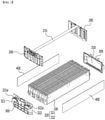
- FIG. 1 is an exploded perspective view illustrating a module structure of a conventional battery module.
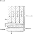
- FIG. 2 is a schematic view illustrating a cross-section of parts that is assembled in a cross-section when the conventional battery module is assembled into a battery pack.
- the conventional battery module consists of a stack of battery cells 10, a busbar frame 20 covering a front and rear surfaces of the stack of battery cells 10, an upper plate 21 connecting the busbar frame 20 at a top of the stack of battery cells 10, a frame 30 that accommodates the stack of battery cells 10, the busbar frame 20 and the upper plate 21 and is made of a metal, a thermally conductive resin layer 11 formed between a lower surface of the frame and the stack of battery cells, an insulating cover 40 formed on an outer side of the busbar frame 20, and an end plate 50 formed of a metal material on an outer side of the insulating cover 40.
- the frame 30 is formed to cover an upper, lower, left and right surfaces of the stack of battery cells 10 and the end plate 50 is made to cover the front and rear surfaces of the stack of battery cells 10, whereby the metal frame is formed in a structure surrounding six surfaces of the stack of battery cells 10, and the thermally conductive resin layer 11 is separately inserted between the lower surface of the stack of battery cells 10 and the metal frame to cool the battery cells 10.
- the conventional battery module has problems that the six surfaces of the stack of battery cells 10 are surrounded with the metal frame, the thermally conductive resin layer 11 is separately inserted and thus, the weight of the battery module becomes relatively heavy, and that a heat sink 32 is formed in a battery pack, and a thermally conductive resin layer 11 and a frame 30 are located between a thermally conductive layer 31 formed on an upper side of the heat sink 32 and the stacks of battery cells 10 as shown in FIG. 2 , so that a cooling path becomes complicated and a cooling performance is deteriorated.
- the present disclosure has been made to solve the above-mentioned problems, and it is an object of the present disclosure to provide a battery module having a structure capable of reducing a weight and reducing costs, and a battery pack comprising the same.
- a battery module and a battery pack comprising the same according to an embodiment of the present disclosure comprise a stack of battery cells in which a plurality of battery cells are staked, an end plate covering front and rear surfaces of the stack of battery cells, a busbar frame formed between the stack of battery cells and the end plate, a sensing member connecting the busbar frames on an upper side of the stack of battery cells, an insulating plate formed between the end plate and the busbar frame, and a side plate covering both side surfaces of the stack of battery cells, wherein mounting portions are formed at both side ends of the end plate, and a lower surface of the stack of battery cells is opened, wherein outermost battery cells of the stack of battery cells are coupled with the side plates and coupling the side plates with the end plates to fix the plurality of battery cells, and wherein a thermally conductive layer is in contact with the lower surface of the stack of battery cells and a heat sink is located a lower side of the thermally conductive layer.
- the end plate and the side plate may be joined to each other by welding.
- the battery module may further comprise an upper plate located on an upper side of the sensing member to cover the upper surface of the stack of battery cells and the sensing member.
- the upper plate may be made of a plastic.
- the upper plate may be formed of a film.
- the side plate may be made of a metal.
- the stack of battery cells and the side plate may be coupled with an adhesive agent.
- the end plate may be coupled to the busbar frame.
- the battery module may further comprise a lower cover covering a lower surface of the stack of battery cells.
- the lower cover may be formed of a film.
- a battery module and a battery pack comprising the same provides effects capable of reducing a weight of the battery module and saving a process cost incurred in manufacturing the battery module, by forming a simple structure that fixes a plurality of battery cells using an end plate and a side plate instead of the existing frame.
- the battery module and the battery pack comprising the same provides an effect capable of increasing a cooling performance by simplifying a cooling path such in a manner that the plurality of battery cells and the thermally conductive layer formed in the battery pack are in contact with each other.
- the battery module and the battery pack comprising the same can reduce a welding line since it is sufficient to couple only the end plate and the side plate, and thus, provide effects capable of lowering the process cost and reducing the manufacturing time.
- terms such as first, second, and the like may be used to describe various components, and the terms are used only to discriminate one component from another component.
- FIG. 3 is an exploded perspective view showing a battery module according to an embodiment of the present disclosure.
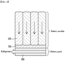
- FIG. 4 is a schematic view showing a cross-section of components that are assembled when a battery module according to an embodiment of the present disclosure is assembled into a battery pack.
- the battery module comprises a stack of battery cells 100 in which a plurality of battery cells are staked, an end plate 300 covering front and rear surfaces of the stack of battery cells, a busbar frame 200 formed between the stack of battery cells and the end plate 300, a sensing member 210 connecting the busbar frames on an upper side of the stack of battery cells, an insulating plate 310 formed between the end plate 300 and the busbar frame 200, and a side plate 400 covering both side surfaces of the stack of battery cells, wherein mounting portions 320 are formed at both side ends of the end plate 300, wherein a lower surface of the stack of battery cells is opened, and wherein outermost battery cells of the stack of battery cells and the side plates 400 are coupled to each other and the side plates 400 and the end plates 300 are coupled to each other to fix the plurality of battery cells.
- the battery cell 100 is a secondary battery and may be configured as a pouch-shaped secondary battery. Such a battery cell 100 may be composed of a plurality of cells, and the plurality of battery cells 100 may be stacked together to form the stack of battery cells such that they can be electrically connected to each other. Each of the plurality of battery cells may include an electrode assembly, a battery case, and an electrode lead protruding from the electrode assembly (not shown).
- the busbar frame 200 is formed on the front and rear surfaces of the stack of battery cells, respectively.
- the busbar frame 200 may be formed by covering the front and rear surfaces of the stack of battery cells so as to electrically connect the electrode leads of the plurality of battery cells 100.
- the sensing member 210 connects the busbar frame 200 formed on the front surface of the stack of battery cells and the busbar frame 200 formed on the rear surface of the stack of battery cells at the upper side of the stack of battery cells.
- Each of the busbar frames 200 formed on the front and rear surfaces of the stack of battery cells may be electrically connected through the sensing member 210.
- the end plate 300 is formed to cover the front and rear surfaces of the stack of battery cells, and may be coupled with the busbar frame 200 to protect the busbar frame 200 and various electrical devices connected thereto from an external impact. Further, the end plate 300 may have a battery module mounting structure as a constitutive element of the frame. In addition, a terminal busbar formed in the busbar frame 200 protrudes to the outside through an opening of the end plate 300, so that the electrical connection can be guided between the busbar frame 200 and an external power source.
- the insulating plate 310 is formed between the stack of battery cells and the end plate 300 to cover the front and rear surfaces of the stack of battery cells.
- the insulating plate 310 is formed to cover the busbar frame 200 and can cut off electrical connection between the busbar frame 200 and the outside.
- the insulating plate 310 may be made of a plastic having an insulating function.
- a mounting portion 320 is formed at both side ends of the end plate 300, and the battery module according to an embodiment of the present disclosure may be coupled to a battery pack through the mounting portion 320.
- the mounting portion 320 may include a first mounting portion 321 formed at one side end of the end plate 300 and a second mounting portion 322 formed at the other side end of the end plate 300.
- Each of the mounting portions may include a coupling hole formed through a perforation in the up and down directions.
- the first mounting portion 321 may include a first coupling hole 321a and the second mounting portion 322 may include a second coupling hole 322a.
- the battery module according to an embodiment of the present disclosure may be coupled to the battery pack through such a coupling hole.
- the side plate 400 is formed to cover both side surfaces of the stack of battery cells.
- the side plate 400 may be made of a metal, and the outermost battery cells formed on both sides of the stack of battery cells and the side plates 400 on both the sides may be bonded with an adhesive agent, respectively, and also be coupled by pressing each other.
- the method of coupling the stack of battery cells and the side plate is not limited thereto, and may be coupled in various ways.
- the end plate 300 and the side plate 400 are coupled to each other to fix the plurality of battery cells 100 located inside the plates.
- a cell swelling phenomenon that may generated in the plurality of battery cells may be controlled through the end plate 300 and the side plate 400 coupled in the above way.
- the end plate 300 and the side plate 400 may be joined to each other by welding.
- a frame is formed to cover upper, lower, left and right surfaces of the stack of battery cells, which makes a weight of the battery module relatively heavy and makes it costly to manufacture the frame.
- the battery module according to an embodiment of the present disclosure can reduce the weight of the battery module and save the cost incurred in manufacturing the battery module by eliminating the use of the conventional frame, and instead fixing and protecting the stack of battery cells with only the end plate and the side plate.
- the battery module according to an embodiment of the present disclosure is required to join only the contact sites of the side plate and the end plate by welding, compared to welding and coupling all the edge parts of the conventional frame and the end plate, the welding line is shortened, and thus the process cost and the manufacturing time can be saved.
- the battery module according to an embodiment of the present disclosure may be formed such that a lower surface of the stack of battery cells 100 is opened.
- the opening of the lower surface of the stack of battery cells 100 means that the lower surface of the stack of battery cells 100 is not covered by the frame or the plate as in the prior art. Therefore, when the battery module is installed to the battery pack, the lower surface of the stack of battery cells can be in contact with a thermally conductive layer 700 formed in the battery pack according to an embodiment of the present disclosure, and connected to a heat sink 800 formed on a lower side of the thermally conductive layer 700 through the thermally conductive layer 700.
- the thermally conductive layer 700 may be expressed as a TIM (thermal interface material), and the thermally conductive layer 700 may transfer a heat generated from the plurality of battery cells 100 in the battery module to the outside of the battery module.
- the heat sink 800 contacts with the thermally conductive layer 700 and can discharge the heat transferred from the thermally conductive layer 700 to the outside through a refrigerant flowing inside the heat sink 800.
- a heat generated from a battery cell could be released to the outside only when it passed through a thermally conductive resin, a frame, a thermally conductive layer, and a heat sink in order.
- the battery cell 100 since the battery cell 100 contacts the thermally conductive layer 700 in the battery pack directly by eliminating the use of the thermally conductive resin and the frame, the heat generated from the battery cell 100 can be directly discharged to the outside through only the thermally conductive layer 700 and the heat sink 800. Accordingly, the battery module of the present disclosure can improve a cooling performance by virtue of simplification of the heat transfer path.
- the thermally conductive resin since there is no need to use the thermally conductive resin, it is possible to reduce the weight of the battery module and save the cost rendered in manufacturing the battery module.
- FIG. 5 is an exploded perspective view showing a battery module in which an upper plate is formed according to a modified embodiment of the present disclosure.
- the battery module according to a modified embodiment of the present disclosure may further comprise the upper plate 500 located on an upper side of the sensing member to cover an upper surface of the stack of battery cells 100 and the sensing member.
- the upper plate 500 may be made of a plastic lighter than a metal, and also formed of a film lighter than the plastic. Accordingly, a weight of the battery module can be lighter than that of the frame upper side structure conventionally formed of metal, while the electric structure of the battery module can be protected on the upper side of the stack of battery cells by the upper plate 500.
- the contents are the same as those described for the battery module and the battery pack according to a modified embodiment of the present disclosure.
- FIG. 6 is an exploded perspective view showing a battery module in which a lower cover is formed according to a modified embodiment of the present disclosure.
- the battery module according to a modified embodiment of the present disclosure may further comprise the lower cover 600 covering a lower surface of the stack of battery cells 100.
- the lower cover 600 may be formed of a film lighter than a metal. Therefore, a weight of the battery module can be lighter than that of the frame lower side structure conventionally formed of the metal, and unexpected damage that may be caused by a lower surface of the stack of battery cells when the battery module is assembled to the battery pack can be prevented through the lower cover 600 in advance.
- the contents are the same as those described for the battery module and the battery pack according to a modified embodiment of the present disclosure.
- the battery module described above may be included in the battery pack.
- the battery pack may have a structure packed by adding a BMS (battery management system) that collects one or more battery modules according to the present embodiment and manages a temperature or a voltage of the battery, a cooling device, and the like.
- BMS battery management system
- a plurality of battery modules may be installed in this battery pack.
- the heat generated from the battery cells can be released to the outside through the heat sink that is brought into contact with the thermally conductive layer by contacting the lower surface of the stack of battery cells formed in the plurality of battery modules with the thermally conductive layer formed in the battery pack.
- the battery pack comprising the same can be applied to various devices.
- a device may be applied to a vehicle such as an electric bicycle, an electric vehicle, or a hybrid vehicle, but the present disclosure is not limited thereto, and is applicable to various devices that can use a battery module, which also belongs to the scope of the present disclosure.
Landscapes
- Chemical & Material Sciences (AREA)
- Chemical Kinetics & Catalysis (AREA)
- Electrochemistry (AREA)
- General Chemical & Material Sciences (AREA)
- Engineering & Computer Science (AREA)
- Manufacturing & Machinery (AREA)
- Inorganic Chemistry (AREA)
- Battery Mounting, Suspending (AREA)
- Connection Of Batteries Or Terminals (AREA)
Abstract
Description
- This application claims the benefit of
Korean Patent Application No. 10-2019-0123773 filed on October 7, 2019 - The present disclosure relates to a battery module and a battery pack comprising the same, and more particularly, to a battery module having a simplified structure and a battery pack comprising the same.
- A secondary battery has attracted much attention as an energy source in various products such as a mobile device and an electric vehicle. The secondary battery is a potent energy resource that can replace the use of existing products using fossil fuels, and is in the spotlight as an environment-friendly energy source because it does not generate byproducts due to energy use.
- Recently, along with a continuous rise of the necessity for a large-capacity secondary battery structure, including the utilization of the secondary battery as an energy storage source, there is a growing demand for a battery pack of a multi-module structure which is an assembly of battery modules in which a plurality of secondary batteries are connected in series/parallel.
- Such a battery module includes a battery cell stack in which a plurality of battery cells are stacked, a frame accommodating the battery cell stack, a busbar frame formed at each of both ends of the battery cell stack, an end plate formed outside the busbar frame and an insulating plate formed inside the end plate.
-
FIG. 1 is an exploded perspective view illustrating a module structure of a conventional battery module.FIG. 2 is a schematic view illustrating a cross-section of parts that is assembled in a cross-section when the conventional battery module is assembled into a battery pack. - Referring to
FIG. 1 , the conventional battery module consists of a stack ofbattery cells 10, a busbar frame 20 covering a front and rear surfaces of the stack ofbattery cells 10, anupper plate 21 connecting the busbar frame 20 at a top of the stack ofbattery cells 10, a frame 30 that accommodates the stack ofbattery cells 10, the busbar frame 20 and theupper plate 21 and is made of a metal, a thermallyconductive resin layer 11 formed between a lower surface of the frame and the stack of battery cells, an insulating cover 40 formed on an outer side of the busbar frame 20, and anend plate 50 formed of a metal material on an outer side of the insulating cover 40. - In this case, the frame 30 is formed to cover an upper, lower, left and right surfaces of the stack of
battery cells 10 and theend plate 50 is made to cover the front and rear surfaces of the stack ofbattery cells 10, whereby the metal frame is formed in a structure surrounding six surfaces of the stack ofbattery cells 10, and the thermallyconductive resin layer 11 is separately inserted between the lower surface of the stack ofbattery cells 10 and the metal frame to cool thebattery cells 10. - However, the conventional battery module has problems that the six surfaces of the stack of
battery cells 10 are surrounded with the metal frame, the thermallyconductive resin layer 11 is separately inserted and thus, the weight of the battery module becomes relatively heavy, and that aheat sink 32 is formed in a battery pack, and a thermallyconductive resin layer 11 and a frame 30 are located between a thermally conductive layer 31 formed on an upper side of theheat sink 32 and the stacks ofbattery cells 10 as shown inFIG. 2 , so that a cooling path becomes complicated and a cooling performance is deteriorated. - The present disclosure has been made to solve the above-mentioned problems, and it is an object of the present disclosure to provide a battery module having a structure capable of reducing a weight and reducing costs, and a battery pack comprising the same.
- It is another object of the present disclosure to provide a battery module having a structure capable of improving a cooling performance, and a battery pack comprising the same.
- It is yet another object of the present disclosure to provide a battery module capable of reducing process costs and manufacturing time, and a battery pack comprising the same.
- However, the problem to be solved by embodiments of the present disclosure is not limited to the above-described problems, and can be variously expanded within the scope of the technical idea included in the present disclosure.
- In order to achieve the above objects, a battery module and a battery pack comprising the same according to an embodiment of the present disclosure comprise a stack of battery cells in which a plurality of battery cells are staked, an end plate covering front and rear surfaces of the stack of battery cells, a busbar frame formed between the stack of battery cells and the end plate, a sensing member connecting the busbar frames on an upper side of the stack of battery cells, an insulating plate formed between the end plate and the busbar frame, and a side plate covering both side surfaces of the stack of battery cells, wherein mounting portions are formed at both side ends of the end plate, and a lower surface of the stack of battery cells is opened, wherein outermost battery cells of the stack of battery cells are coupled with the side plates and coupling the side plates with the end plates to fix the plurality of battery cells, and wherein a thermally conductive layer is in contact with the lower surface of the stack of battery cells and a heat sink is located a lower side of the thermally conductive layer.
- The end plate and the side plate may be joined to each other by welding.
- The battery module may further comprise an upper plate located on an upper side of the sensing member to cover the upper surface of the stack of battery cells and the sensing member.
- The upper plate may be made of a plastic.
- The upper plate may be formed of a film.
- The side plate may be made of a metal.
- The stack of battery cells and the side plate may be coupled with an adhesive agent. The end plate may be coupled to the busbar frame.
- The battery module may further comprise a lower cover covering a lower surface of the stack of battery cells.
- The lower cover may be formed of a film.
- A battery module and a battery pack comprising the same according to an embodiment of the present disclosure provides effects capable of reducing a weight of the battery module and saving a process cost incurred in manufacturing the battery module, by forming a simple structure that fixes a plurality of battery cells using an end plate and a side plate instead of the existing frame.
- Further, the battery module and the battery pack comprising the same according to an embodiment of the present disclosure provides an effect capable of increasing a cooling performance by simplifying a cooling path such in a manner that the plurality of battery cells and the thermally conductive layer formed in the battery pack are in contact with each other.
- Further, since the battery module and the battery pack comprising the same according to an embodiment of the present disclosure can reduce a welding line since it is sufficient to couple only the end plate and the side plate, and thus, provide effects capable of lowering the process cost and reducing the manufacturing time.
- The effects of the present disclosure are not limited to the effects mentioned above and additional other effects not described above will be clearly understood from the description of the appended claims by those skilled in the art.
-
-
FIG. 1 is an exploded perspective view showing a module structure of a conventional battery module. -
FIG. 2 is a schematic view illustrating a cross-section of parts that is assembled in a cross-section when the conventional battery module is assembled into a battery pack. -
FIG. 3 is an exploded perspective view showing a battery module according to an embodiment of the present disclosure. -
FIG. 4 is a schematic view showing a cross-section of components that are assembled when the battery module according to an embodiment of the present disclosure is assembled into a battery pack. -
FIG. 5 is an exploded perspective view showing a battery module formed with an upper plate according to a modified embodiment of the present disclosure. -
FIG. 6 is an exploded perspective view showing a battery module formed with a lower cover according to a modified embodiment of the present disclosure. - It should be appreciated that the exemplary embodiments, which will be described below, are illustratively described to help understand the present disclosure, and the present disclosure may be variously modified to be carried out differently from the exemplary embodiments described herein. However, in the description of the present disclosure, the specific descriptions and illustrations of publicly known functions or constituent elements will be omitted when it is determined that the specific descriptions and illustrations may unnecessarily obscure the subject matter of the present disclosure. In addition, to help understand the present disclosure, the accompanying drawings are not illustrated based on actual scales, but parts of the constituent elements may be exaggerated in size.
- As used herein, terms such as first, second, and the like may be used to describe various components, and the terms are used only to discriminate one component from another component.
- Further, the terms used herein are used only to describe exemplary embodiments, and are not intended to limit the present disclosure. A singular expression includes a plural expression unless they have definitely opposite meanings in the context. It should be understood that the terms "comprise", "include", and "have" as used herein are intended to designate the presence of stated features, numbers, steps, constitutional elements, or combinations thereof, but it should be understood that they do not preclude a possibility of existence or addition of one or more other features, numbers, steps, constitutional elements, or combinations thereof.
- Hereinafter, a battery module according to an embodiment of the present disclosure will be described with reference to
FIG. 3 andFIG. 4 . -
FIG. 3 is an exploded perspective view showing a battery module according to an embodiment of the present disclosure.FIG. 4 is a schematic view showing a cross-section of components that are assembled when a battery module according to an embodiment of the present disclosure is assembled into a battery pack. - Referring to
FIG. 3 andFIG. 4 , the battery module according to an embodiment of the present disclosure comprises a stack ofbattery cells 100 in which a plurality of battery cells are staked, anend plate 300 covering front and rear surfaces of the stack of battery cells, abusbar frame 200 formed between the stack of battery cells and theend plate 300, asensing member 210 connecting the busbar frames on an upper side of the stack of battery cells, aninsulating plate 310 formed between theend plate 300 and thebusbar frame 200, and aside plate 400 covering both side surfaces of the stack of battery cells, wherein mountingportions 320 are formed at both side ends of theend plate 300, wherein a lower surface of the stack of battery cells is opened, and wherein outermost battery cells of the stack of battery cells and theside plates 400 are coupled to each other and theside plates 400 and theend plates 300 are coupled to each other to fix the plurality of battery cells. - The
battery cell 100 is a secondary battery and may be configured as a pouch-shaped secondary battery. Such abattery cell 100 may be composed of a plurality of cells, and the plurality ofbattery cells 100 may be stacked together to form the stack of battery cells such that they can be electrically connected to each other. Each of the plurality of battery cells may include an electrode assembly, a battery case, and an electrode lead protruding from the electrode assembly (not shown). - The
busbar frame 200 is formed on the front and rear surfaces of the stack of battery cells, respectively. Thebusbar frame 200 may be formed by covering the front and rear surfaces of the stack of battery cells so as to electrically connect the electrode leads of the plurality ofbattery cells 100. - The
sensing member 210 connects thebusbar frame 200 formed on the front surface of the stack of battery cells and thebusbar frame 200 formed on the rear surface of the stack of battery cells at the upper side of the stack of battery cells. Each of thebusbar frames 200 formed on the front and rear surfaces of the stack of battery cells may be electrically connected through thesensing member 210. - The
end plate 300 is formed to cover the front and rear surfaces of the stack of battery cells, and may be coupled with thebusbar frame 200 to protect thebusbar frame 200 and various electrical devices connected thereto from an external impact. Further, theend plate 300 may have a battery module mounting structure as a constitutive element of the frame. In addition, a terminal busbar formed in thebusbar frame 200 protrudes to the outside through an opening of theend plate 300, so that the electrical connection can be guided between thebusbar frame 200 and an external power source. - The
insulating plate 310 is formed between the stack of battery cells and theend plate 300 to cover the front and rear surfaces of the stack of battery cells. Theinsulating plate 310 is formed to cover thebusbar frame 200 and can cut off electrical connection between thebusbar frame 200 and the outside. According to an embodiment of the present disclosure, the insulatingplate 310 may be made of a plastic having an insulating function. - A mounting
portion 320 is formed at both side ends of theend plate 300, and the battery module according to an embodiment of the present disclosure may be coupled to a battery pack through the mountingportion 320. As shown inFIG. 3 , the mountingportion 320 may include a first mountingportion 321 formed at one side end of theend plate 300 and a second mountingportion 322 formed at the other side end of theend plate 300. Each of the mounting portions may include a coupling hole formed through a perforation in the up and down directions. The first mountingportion 321 may include afirst coupling hole 321a and the second mountingportion 322 may include asecond coupling hole 322a. The battery module according to an embodiment of the present disclosure may be coupled to the battery pack through such a coupling hole. - The
side plate 400 is formed to cover both side surfaces of the stack of battery cells. According to an embodiment of the present disclosure, theside plate 400 may be made of a metal, and the outermost battery cells formed on both sides of the stack of battery cells and theside plates 400 on both the sides may be bonded with an adhesive agent, respectively, and also be coupled by pressing each other. However, the method of coupling the stack of battery cells and the side plate is not limited thereto, and may be coupled in various ways. - The
end plate 300 and theside plate 400 are coupled to each other to fix the plurality ofbattery cells 100 located inside the plates. A cell swelling phenomenon that may generated in the plurality of battery cells may be controlled through theend plate 300 and theside plate 400 coupled in the above way. According to an embodiment of the present disclosure, theend plate 300 and theside plate 400 may be joined to each other by welding. - In a battery module of the prior art, a frame is formed to cover upper, lower, left and right surfaces of the stack of battery cells, which makes a weight of the battery module relatively heavy and makes it costly to manufacture the frame. However, the battery module according to an embodiment of the present disclosure can reduce the weight of the battery module and save the cost incurred in manufacturing the battery module by eliminating the use of the conventional frame, and instead fixing and protecting the stack of battery cells with only the end plate and the side plate. In addition, since the battery module according to an embodiment of the present disclosure is required to join only the contact sites of the side plate and the end plate by welding, compared to welding and coupling all the edge parts of the conventional frame and the end plate, the welding line is shortened, and thus the process cost and the manufacturing time can be saved.
- The battery module according to an embodiment of the present disclosure may be formed such that a lower surface of the stack of
battery cells 100 is opened. The opening of the lower surface of the stack ofbattery cells 100 means that the lower surface of the stack ofbattery cells 100 is not covered by the frame or the plate as in the prior art. Therefore, when the battery module is installed to the battery pack, the lower surface of the stack of battery cells can be in contact with a thermallyconductive layer 700 formed in the battery pack according to an embodiment of the present disclosure, and connected to aheat sink 800 formed on a lower side of the thermallyconductive layer 700 through the thermallyconductive layer 700. - The thermally
conductive layer 700 may be expressed as a TIM (thermal interface material), and the thermallyconductive layer 700 may transfer a heat generated from the plurality ofbattery cells 100 in the battery module to the outside of the battery module. Theheat sink 800 contacts with the thermallyconductive layer 700 and can discharge the heat transferred from the thermallyconductive layer 700 to the outside through a refrigerant flowing inside theheat sink 800. - As shown in
FIG. 2 of the prior art, a heat generated from a battery cell could be released to the outside only when it passed through a thermally conductive resin, a frame, a thermally conductive layer, and a heat sink in order. However, according to an embodiment of the present disclosure, since thebattery cell 100 contacts the thermallyconductive layer 700 in the battery pack directly by eliminating the use of the thermally conductive resin and the frame, the heat generated from thebattery cell 100 can be directly discharged to the outside through only the thermallyconductive layer 700 and theheat sink 800. Accordingly, the battery module of the present disclosure can improve a cooling performance by virtue of simplification of the heat transfer path. In addition, since there is no need to use the thermally conductive resin, it is possible to reduce the weight of the battery module and save the cost rendered in manufacturing the battery module. - Hereinafter, a battery module formed with an upper plate according to a modified embodiment of the present disclosure will be described.
-
FIG. 5 is an exploded perspective view showing a battery module in which an upper plate is formed according to a modified embodiment of the present disclosure. - Referring to
FIG. 5 , the battery module according to a modified embodiment of the present disclosure may further comprise theupper plate 500 located on an upper side of the sensing member to cover an upper surface of the stack ofbattery cells 100 and the sensing member. - The
upper plate 500 according to a modified embodiment of the present disclosure may be made of a plastic lighter than a metal, and also formed of a film lighter than the plastic. Accordingly, a weight of the battery module can be lighter than that of the frame upper side structure conventionally formed of metal, while the electric structure of the battery module can be protected on the upper side of the stack of battery cells by theupper plate 500. - Except for the above-described contents, the contents are the same as those described for the battery module and the battery pack according to a modified embodiment of the present disclosure.
- Hereinafter, a battery module formed with a lower cover according to a modified embodiment of the present disclosure will be described.
-
FIG. 6 is an exploded perspective view showing a battery module in which a lower cover is formed according to a modified embodiment of the present disclosure. - Referring to
FIG. 6 , the battery module according to a modified embodiment of the present disclosure may further comprise thelower cover 600 covering a lower surface of the stack ofbattery cells 100. According to a modified embodiment of the present disclosure, thelower cover 600 may be formed of a film lighter than a metal. Therefore, a weight of the battery module can be lighter than that of the frame lower side structure conventionally formed of the metal, and unexpected damage that may be caused by a lower surface of the stack of battery cells when the battery module is assembled to the battery pack can be prevented through thelower cover 600 in advance. - Except for the above-described contents, the contents are the same as those described for the battery module and the battery pack according to a modified embodiment of the present disclosure.
- The battery module described above may be included in the battery pack. The battery pack may have a structure packed by adding a BMS (battery management system) that collects one or more battery modules according to the present embodiment and manages a temperature or a voltage of the battery, a cooling device, and the like. A plurality of battery modules may be installed in this battery pack. The heat generated from the battery cells can be released to the outside through the heat sink that is brought into contact with the thermally conductive layer by contacting the lower surface of the stack of battery cells formed in the plurality of battery modules with the thermally conductive layer formed in the battery pack.
- The battery pack comprising the same can be applied to various devices. Such a device may be applied to a vehicle such as an electric bicycle, an electric vehicle, or a hybrid vehicle, but the present disclosure is not limited thereto, and is applicable to various devices that can use a battery module, which also belongs to the scope of the present disclosure.
- Although the invention has been shown and described with reference to the preferred embodiments, the scope of the present disclosure is not limited thereto, and numerous other modifications and embodiments can be devised by those skilled in the art that will fall within the spirit and scope of the principles of the invention described in the appended claims. Further, these modified embodiments should not be understood individually from the technical spirit or perspective of the present disclosure.
-
- 100:
- battery cell
- 200:
- busbar frame
- 210:
- sensing member
- 300:
- end plate
- 310:
- insulating plate
- 320:
- mounting portion
- 321, 322:
- first and second mounting portions
- 321a, 322a:
- first and second coupling holes
- 500:
- upper plate
- 600:
- lower cover
- 700:
- thermally conductive layer
- 800:
- heat sink
Claims (10)
- A battery module comprising:a stack of battery cells in which a plurality of battery cells are staked,an end plate covering front and rear surfaces of the stack of battery cells,a busbar frame formed between the stack of battery cells and the end plate,a sensing member connecting the busbar frames on an upper side of the stack of battery cells,an insulating plate formed between the end plate and the busbar frame, anda side plate covering both side surfaces of the stack of battery cells,wherein mounting portions are formed at both side ends of the end plate,wherein a lower surface of the stack of battery cells is opened, andwherein outermost battery cells of the stack of battery cells and the side plates are coupled to each other to fix the plurality of battery cells.
- The battery module according to claim 1,
wherein the end plate and the side plate are joined to each other by welding. - The battery module according to claim 1,
further comprising an upper plate located on an upper side of the sensing member to cover the upper surface of the stack of battery cells and the sensing member. - The battery module according to claim 3, wherein the upper plate is formed of a plastic or a film.
- The battery module according to claim 1, wherein the side plate is made of a metal.
- The battery module according to claim 1, wherein the stack of battery cells and the side plate are coupled with an adhesive agent.
- The battery module according to claim 1, wherein the end plate is coupled to the busbar frame.
- The battery module according to claim 1, further comprising a lower cover covering a lower surface of the stack of battery cells.
- The battery module according to claim 8, wherein the lower cover is formed of a film.
- A battery pack comprising:a battery module according to claim 1;a thermally conductive layer that is in contact with a lower surface of a stack of battery cells on a lower side of the battery module; anda heat sink located on a lower side of the thermally conductive layer.
Applications Claiming Priority (2)
| Application Number | Priority Date | Filing Date | Title |
|---|---|---|---|
| KR1020190123773A KR102473336B1 (en) | 2019-10-07 | 2019-10-07 | Battery module and battery pack including the same |
| PCT/KR2020/008067 WO2021071052A1 (en) | 2019-10-07 | 2020-06-22 | Battery module and battery pack including same |
Publications (2)
| Publication Number | Publication Date |
|---|---|
| EP3952005A1 true EP3952005A1 (en) | 2022-02-09 |
| EP3952005A4 EP3952005A4 (en) | 2022-06-22 |
Family
ID=75437198
Family Applications (1)
| Application Number | Title | Priority Date | Filing Date |
|---|---|---|---|
| EP20873701.5A Pending EP3952005A4 (en) | 2019-10-07 | 2020-06-22 | BATTERY MODULE AND BATTERY PACK INCLUDING THE SAME |
Country Status (6)
| Country | Link |
|---|---|
| US (1) | US12548833B2 (en) |
| EP (1) | EP3952005A4 (en) |
| JP (1) | JP7262880B2 (en) |
| KR (1) | KR102473336B1 (en) |
| CN (1) | CN113728502A (en) |
| WO (1) | WO2021071052A1 (en) |
Cited By (2)
| Publication number | Priority date | Publication date | Assignee | Title |
|---|---|---|---|---|
| EP4451446A4 (en) * | 2022-09-23 | 2025-05-07 | LG Energy Solution, Ltd. | BATTERY MODULE AND BATTERY PACK |
| EP4475282A4 (en) * | 2022-12-01 | 2026-03-04 | Lg Energy Solution Ltd | Battery pack |
Families Citing this family (5)
| Publication number | Priority date | Publication date | Assignee | Title |
|---|---|---|---|---|
| US12126049B2 (en) * | 2020-06-11 | 2024-10-22 | Calb Co., Ltd. | Battery module |
| KR102848976B1 (en) * | 2020-12-24 | 2025-08-21 | 에스케이온 주식회사 | Pouch Type Battery Cell and Battery Pack Including the Same |
| KR102852558B1 (en) * | 2021-08-25 | 2025-08-29 | 주식회사 엘지에너지솔루션 | Battery pack and vehicle comprising the battery pack |
| KR20230046394A (en) * | 2021-09-30 | 2023-04-06 | 현대자동차주식회사 | Battery heat radiation unit and battery case for vehicle |
| JP2025517507A (en) * | 2022-05-27 | 2025-06-05 | エルジー エナジー ソリューション リミテッド | Battery module case and battery module including same |
Family Cites Families (63)
| Publication number | Priority date | Publication date | Assignee | Title |
|---|---|---|---|---|
| JP2005243268A (en) | 2004-02-24 | 2005-09-08 | Nec Tokin Corp | Battery pack |
| WO2007102670A1 (en) | 2006-03-06 | 2007-09-13 | Lg Chem, Ltd. | Middle or large-sized battery module |
| DE102008010825A1 (en) * | 2008-02-23 | 2009-08-27 | Daimler Ag | Battery with a heat conducting plate and several single cells |
| DE102008010828A1 (en) * | 2008-02-23 | 2009-08-27 | Daimler Ag | Battery with several single cells |
| JP5358251B2 (en) * | 2009-03-31 | 2013-12-04 | 日立ビークルエナジー株式会社 | Power storage module and power storage device |
| CN102356504B (en) | 2009-04-01 | 2014-07-30 | 株式会社Lg化学 | Battery modules with improved safety |
| JP5315311B2 (en) * | 2010-08-31 | 2013-10-16 | トヨタ自動車株式会社 | Power storage device |
| WO2012043594A1 (en) * | 2010-09-30 | 2012-04-05 | 三洋電機株式会社 | Assembled battery and vehicle provided with same |
| DE102011015152A1 (en) * | 2011-03-25 | 2012-09-27 | Li-Tec Battery Gmbh | Energy storage device, energy storage cell and Wärmeleitelement with elastic means |
| JP5831924B2 (en) | 2011-03-31 | 2015-12-09 | Necエナジーデバイス株式会社 | Battery pack |
| JP2012248339A (en) * | 2011-05-25 | 2012-12-13 | Sanyo Electric Co Ltd | Power unit for electric power and vehicle with power unit |
| JP2013012441A (en) * | 2011-06-30 | 2013-01-17 | Sanyo Electric Co Ltd | Electric power source device and vehicle including the same |
| US9660231B2 (en) | 2012-02-03 | 2017-05-23 | Samsung Sdi Co., Ltd. | Battery pack |
| JP5916500B2 (en) * | 2012-04-27 | 2016-05-11 | オートモーティブエナジーサプライ株式会社 | Assembled battery |
| KR20140064418A (en) | 2012-11-20 | 2014-05-28 | 에스케이이노베이션 주식회사 | Secondary battery module |
| US20160072116A1 (en) | 2013-03-22 | 2016-03-10 | Automotive Energy Supply Corporation | Battery unit and battery module having stacked battery units |
| KR20150024724A (en) * | 2013-08-27 | 2015-03-09 | 삼성에스디아이 주식회사 | Battery pack |
| US9368882B2 (en) * | 2013-11-15 | 2016-06-14 | Yazaki North America, Inc. | Electrical device with a busbar assembly having a frame providing access for laser welding |
| KR101546002B1 (en) | 2013-11-27 | 2015-08-21 | 코칩 주식회사 | electrochemical energy storage device |
| JP5892148B2 (en) | 2013-12-04 | 2016-03-23 | 株式会社豊田自動織機 | Battery module unit |
| JP6110336B2 (en) * | 2014-05-19 | 2017-04-05 | 本田技研工業株式会社 | Power storage module |
| CN107078243B (en) * | 2014-06-20 | 2020-04-24 | 罗伯特·博世有限公司 | Battery module with cell fixation |
| TWM491952U (en) * | 2014-08-20 | 2014-12-11 | Tainergy Tech Co Ltd | Solar cell module |
| US9397376B2 (en) | 2014-09-25 | 2016-07-19 | Atieva, Inc. | Battery pack with segmented, electrically isolated heat sink |
| US9620830B2 (en) | 2014-12-16 | 2017-04-11 | Xinen Technology Hong Kong Company, Ltd. | Vehicle battery module with cooling and safety features |
| DE102015200390A1 (en) | 2015-01-14 | 2016-07-14 | Robert Bosch Gmbh | Battery with thermal insulation |
| KR102009443B1 (en) | 2015-06-19 | 2019-08-12 | 주식회사 엘지화학 | Cartridge And Battery Module Comprising The Same |
| KR102053963B1 (en) | 2015-07-07 | 2019-12-09 | 주식회사 엘지화학 | Battery pack and vehicle comprising the same |
| JP6794617B2 (en) * | 2015-09-18 | 2020-12-02 | 株式会社Gsユアサ | Power storage device |
| WO2017052296A1 (en) | 2015-09-24 | 2017-03-30 | 주식회사 엘지화학 | Battery module |
| KR102024326B1 (en) | 2015-10-14 | 2019-09-23 | 주식회사 엘지화학 | Battery module and battery pack comprising the smae |
| CN105609895A (en) | 2016-03-07 | 2016-05-25 | 宁德时代新能源科技股份有限公司 | battery pack thermal management system |
| KR102112716B1 (en) | 2016-03-16 | 2020-05-19 | 주식회사 엘지화학 | Battery module, battery pack the battery module and vehicle comprising the battery pack |
| KR101647825B1 (en) | 2016-04-11 | 2016-08-11 | 김정연 | Battery Pack for Electric Vehicles |
| KR102102927B1 (en) | 2016-10-06 | 2020-04-21 | 주식회사 엘지화학 | Battery module, battery pack comprising the battery module and vehicle comprising the battery pack |
| JP6412904B2 (en) * | 2016-10-26 | 2018-10-24 | 本田技研工業株式会社 | Battery module |
| CN110114904B (en) | 2016-12-27 | 2022-07-15 | 裕罗有限公司 | Busbar assembly and bracket assembly |
| KR102033001B1 (en) | 2017-02-28 | 2019-10-16 | 주식회사 유라코퍼레이션 | Frame assembly, method of manufacturing frame assembly, and method of manufacturing battery module |
| KR101996449B1 (en) | 2017-09-06 | 2019-07-03 | 주식회사 유라코퍼레이션 | Battery cell module with protective structure of fpcb |
| RS61814B1 (en) | 2016-12-27 | 2021-06-30 | Yura Corporation Co Ltd | Flexible circuit board and frame assembly including same |
| KR20180080813A (en) | 2017-01-05 | 2018-07-13 | 에이치엘그린파워 주식회사 | Battery module housing structure for improving cooling performance and Method for assembling the same |
| WO2018159928A1 (en) | 2017-02-28 | 2018-09-07 | 주식회사 유라코퍼레이션 | Frame assembly and method for manufacturing same |
| JP6688762B2 (en) * | 2017-05-23 | 2020-04-28 | 矢崎総業株式会社 | Battery temperature sensor and its mounting structure |
| KR102050025B1 (en) * | 2017-09-04 | 2020-01-08 | 주식회사 엘지화학 | Battery Pack of coolant direct contact cooling type |
| KR102364283B1 (en) | 2017-12-01 | 2022-02-16 | 주식회사 엘지에너지솔루션 | Battery Module Having Heat Dissipation Plate |
| KR102259416B1 (en) | 2017-12-14 | 2021-06-01 | 주식회사 엘지에너지솔루션 | Battery Module Having Bus bar Assembly |
| KR102270828B1 (en) | 2017-12-19 | 2021-06-29 | 주식회사 엘지에너지솔루션 | Battery Module Having Bus-Bar Assembly |
| CN207818670U (en) | 2017-12-21 | 2018-09-04 | 宁德时代新能源科技股份有限公司 | battery module |
| CN109994798B (en) | 2017-12-26 | 2025-08-15 | Sk新能源株式会社 | Battery module and method for manufacturing same |
| KR102388127B1 (en) | 2018-01-31 | 2022-04-19 | 주식회사 엘지에너지솔루션 | Top cover, battery module using the same, and battery pack and vehicle including the same |
| WO2019159732A1 (en) * | 2018-02-14 | 2019-08-22 | 株式会社Gsユアサ | Power storage device |
| KR102250204B1 (en) * | 2018-03-07 | 2021-05-10 | 주식회사 엘지화학 | Battery module, battery pack comprising the battery module and vehicle comprising the battery pack |
| KR102150679B1 (en) | 2018-03-13 | 2020-09-01 | 주식회사 엘지화학 | Battery module, battery pack comprising the battery module and vehicle comprising the battery pack |
| KR102725066B1 (en) | 2018-03-16 | 2024-11-04 | 현대모비스 주식회사 | Housing structure of Battery module |
| KR102277035B1 (en) | 2018-03-21 | 2021-07-13 | 주식회사 엘지에너지솔루션 | Battery module, battery pack comprising the battery module and vehicle comprising the battery pack |
| KR20190112583A (en) | 2018-03-26 | 2019-10-07 | 에이치엘그린파워 주식회사 | Battery module structure for Indirect water cooling type using heat pipe |
| CN208478403U (en) | 2018-05-28 | 2019-02-05 | 欣旺达电动汽车电池有限公司 | A square battery module connection structure |
| CN108666494B (en) | 2018-06-29 | 2023-12-22 | 天津市捷威动力工业有限公司 | Large module group structure of flexible soft-package battery |
| KR102825806B1 (en) | 2019-02-08 | 2025-06-25 | 에스케이온 주식회사 | Battery Module |
| CN209747613U (en) * | 2019-06-28 | 2019-12-06 | 江苏时代新能源科技有限公司 | battery module |
| WO2021024776A1 (en) | 2019-08-03 | 2021-02-11 | 三洋電機株式会社 | Power supply device, electric vehicle comprising said power supply device, and power storage device |
| US11302996B2 (en) | 2019-08-19 | 2022-04-12 | GM Global Technology Operations LLC | Battery modules with integrated interconnect board assemblies having cell tab comb features |
| KR20230134338A (en) * | 2022-03-14 | 2023-09-21 | 에스케이온 주식회사 | End plate assembly including thermistor, battery module and battery pack including the same |
-
2019
- 2019-10-07 KR KR1020190123773A patent/KR102473336B1/en active Active
-
2020
- 2020-06-22 CN CN202080031565.XA patent/CN113728502A/en active Pending
- 2020-06-22 JP JP2021547250A patent/JP7262880B2/en active Active
- 2020-06-22 US US17/603,496 patent/US12548833B2/en active Active
- 2020-06-22 WO PCT/KR2020/008067 patent/WO2021071052A1/en not_active Ceased
- 2020-06-22 EP EP20873701.5A patent/EP3952005A4/en active Pending
Cited By (2)
| Publication number | Priority date | Publication date | Assignee | Title |
|---|---|---|---|---|
| EP4451446A4 (en) * | 2022-09-23 | 2025-05-07 | LG Energy Solution, Ltd. | BATTERY MODULE AND BATTERY PACK |
| EP4475282A4 (en) * | 2022-12-01 | 2026-03-04 | Lg Energy Solution Ltd | Battery pack |
Also Published As
| Publication number | Publication date |
|---|---|
| KR102473336B1 (en) | 2022-12-01 |
| US20220181733A1 (en) | 2022-06-09 |
| EP3952005A4 (en) | 2022-06-22 |
| KR20210041284A (en) | 2021-04-15 |
| US12548833B2 (en) | 2026-02-10 |
| JP7262880B2 (en) | 2023-04-24 |
| JP2022520585A (en) | 2022-03-31 |
| CN113728502A (en) | 2021-11-30 |
| WO2021071052A1 (en) | 2021-04-15 |
Similar Documents
| Publication | Publication Date | Title |
|---|---|---|
| US11916244B2 (en) | Battery module including partition member | |
| US12548833B2 (en) | Battery module and battery pack comprising same | |
| EP3866252A1 (en) | Battery module and battery pack comprising same | |
| US12237485B2 (en) | Battery module and battery pack including the same | |
| KR20200097511A (en) | Battery Module | |
| EP3958379A1 (en) | Battery module and battery pack comprising same | |
| US12548822B2 (en) | Battery pack and device including the same | |
| KR102464825B1 (en) | Battery module and battery pack including the same | |
| US20220158284A1 (en) | Battery Module and Battery Pack Including the Same | |
| EP3916893A1 (en) | Battery module and battery pack including same | |
| EP3961792A1 (en) | Battery module and battery pack including same | |
| JP2023535947A (en) | Battery modules and battery packs containing the same | |
| EP4428990A1 (en) | Battery module and battery pack comprising same | |
| JP2023537015A (en) | Battery modules and battery packs containing the same | |
| EP4391156A1 (en) | Battery pack and device comprising same | |
| EP4131580A1 (en) | Battery module and battery pack including same | |
| EP4270603B1 (en) | Battery module and battery pack including the same | |
| EP4142020B1 (en) | Battery module and battery pack including the same | |
| US12294069B2 (en) | Battery module and manufacturing method thereof | |
| EP4181274A1 (en) | Battery module and battery pack including same | |
| KR20220121594A (en) | Battery module and battery pack including same | |
| EP4618247A1 (en) | Battery module and battery pack comprising same | |
| KR20230036864A (en) | Battery module and battery pack including the same |
Legal Events
| Date | Code | Title | Description |
|---|---|---|---|
| STAA | Information on the status of an ep patent application or granted ep patent |
Free format text: STATUS: THE INTERNATIONAL PUBLICATION HAS BEEN MADE |
|
| PUAI | Public reference made under article 153(3) epc to a published international application that has entered the european phase |
Free format text: ORIGINAL CODE: 0009012 |
|
| STAA | Information on the status of an ep patent application or granted ep patent |
Free format text: STATUS: REQUEST FOR EXAMINATION WAS MADE |
|
| 17P | Request for examination filed |
Effective date: 20211029 |
|
| AK | Designated contracting states |
Kind code of ref document: A1 Designated state(s): AL AT BE BG CH CY CZ DE DK EE ES FI FR GB GR HR HU IE IS IT LI LT LU LV MC MK MT NL NO PL PT RO RS SE SI SK SM TR |
|
| RAP3 | Party data changed (applicant data changed or rights of an application transferred) |
Owner name: LG ENERGY SOLUTION, LTD. |
|
| A4 | Supplementary search report drawn up and despatched |
Effective date: 20220519 |
|
| RIC1 | Information provided on ipc code assigned before grant |
Ipc: H01M 10/613 20140101ALI20220513BHEP Ipc: H01M 10/6551 20140101ALI20220513BHEP Ipc: H01M 10/48 20060101AFI20220513BHEP |
|
| DAV | Request for validation of the european patent (deleted) | ||
| DAX | Request for extension of the european patent (deleted) |