EP3951580A1 - Information processing device, touch panel display method, and touch panel display program - Google Patents
Information processing device, touch panel display method, and touch panel display program Download PDFInfo
- Publication number
- EP3951580A1 EP3951580A1 EP21188541.3A EP21188541A EP3951580A1 EP 3951580 A1 EP3951580 A1 EP 3951580A1 EP 21188541 A EP21188541 A EP 21188541A EP 3951580 A1 EP3951580 A1 EP 3951580A1
- Authority
- EP
- European Patent Office
- Prior art keywords
- disable
- layer
- screen
- touch
- interrupt
- Prior art date
- Legal status (The legal status is an assumption and is not a legal conclusion. Google has not performed a legal analysis and makes no representation as to the accuracy of the status listed.)
- Withdrawn
Links
Images



Classifications
-
- G—PHYSICS
- G06—COMPUTING OR CALCULATING; COUNTING
- G06F—ELECTRIC DIGITAL DATA PROCESSING
- G06F3/00—Input arrangements for transferring data to be processed into a form capable of being handled by the computer; Output arrangements for transferring data from processing unit to output unit, e.g. interface arrangements
- G06F3/01—Input arrangements or combined input and output arrangements for interaction between user and computer
- G06F3/048—Interaction techniques based on graphical user interfaces [GUI]
- G06F3/0487—Interaction techniques based on graphical user interfaces [GUI] using specific features provided by the input device, e.g. functions controlled by the rotation of a mouse with dual sensing arrangements, or of the nature of the input device, e.g. tap gestures based on pressure sensed by a digitiser
- G06F3/0488—Interaction techniques based on graphical user interfaces [GUI] using specific features provided by the input device, e.g. functions controlled by the rotation of a mouse with dual sensing arrangements, or of the nature of the input device, e.g. tap gestures based on pressure sensed by a digitiser using a touch-screen or digitiser, e.g. input of commands through traced gestures
-
- H—ELECTRICITY
- H04—ELECTRIC COMMUNICATION TECHNIQUE
- H04N—PICTORIAL COMMUNICATION, e.g. TELEVISION
- H04N1/00—Scanning, transmission or reproduction of documents or the like, e.g. facsimile transmission; Details thereof
- H04N1/0035—User-machine interface; Control console
- H04N1/00352—Input means
- H04N1/00395—Arrangements for reducing operator input
-
- G—PHYSICS
- G03—PHOTOGRAPHY; CINEMATOGRAPHY; ANALOGOUS TECHNIQUES USING WAVES OTHER THAN OPTICAL WAVES; ELECTROGRAPHY; HOLOGRAPHY
- G03G—ELECTROGRAPHY; ELECTROPHOTOGRAPHY; MAGNETOGRAPHY
- G03G15/00—Apparatus for electrographic processes using a charge pattern
- G03G15/50—Machine control of apparatus for electrographic processes using a charge pattern, e.g. regulating differents parts of the machine, multimode copiers, microprocessor control
- G03G15/5016—User-machine interface; Display panels; Control console
-
- G—PHYSICS
- G06—COMPUTING OR CALCULATING; COUNTING
- G06F—ELECTRIC DIGITAL DATA PROCESSING
- G06F3/00—Input arrangements for transferring data to be processed into a form capable of being handled by the computer; Output arrangements for transferring data from processing unit to output unit, e.g. interface arrangements
- G06F3/01—Input arrangements or combined input and output arrangements for interaction between user and computer
- G06F3/03—Arrangements for converting the position or the displacement of a member into a coded form
- G06F3/041—Digitisers, e.g. for touch screens or touch pads, characterised by the transducing means
- G06F3/0416—Control or interface arrangements specially adapted for digitisers
-
- H—ELECTRICITY
- H04—ELECTRIC COMMUNICATION TECHNIQUE
- H04N—PICTORIAL COMMUNICATION, e.g. TELEVISION
- H04N1/00—Scanning, transmission or reproduction of documents or the like, e.g. facsimile transmission; Details thereof
- H04N1/00002—Diagnosis, testing or measuring; Detecting, analysing or monitoring not otherwise provided for
- H04N1/00026—Methods therefor
- H04N1/00037—Detecting, i.e. determining the occurrence of a predetermined state
-
- H—ELECTRICITY
- H04—ELECTRIC COMMUNICATION TECHNIQUE
- H04N—PICTORIAL COMMUNICATION, e.g. TELEVISION
- H04N1/00—Scanning, transmission or reproduction of documents or the like, e.g. facsimile transmission; Details thereof
- H04N1/00002—Diagnosis, testing or measuring; Detecting, analysing or monitoring not otherwise provided for
- H04N1/00071—Diagnosis, testing or measuring; Detecting, analysing or monitoring not otherwise provided for characterised by the action taken
- H04N1/00074—Indicating or reporting
-
- H—ELECTRICITY
- H04—ELECTRIC COMMUNICATION TECHNIQUE
- H04N—PICTORIAL COMMUNICATION, e.g. TELEVISION
- H04N1/00—Scanning, transmission or reproduction of documents or the like, e.g. facsimile transmission; Details thereof
- H04N1/0035—User-machine interface; Control console
- H04N1/00405—Output means
- H04N1/00408—Display of information to the user, e.g. menus
- H04N1/00411—Display of information to the user, e.g. menus the display also being used for user input, e.g. touch screen
-
- H—ELECTRICITY
- H04—ELECTRIC COMMUNICATION TECHNIQUE
- H04N—PICTORIAL COMMUNICATION, e.g. TELEVISION
- H04N1/00—Scanning, transmission or reproduction of documents or the like, e.g. facsimile transmission; Details thereof
- H04N1/0035—User-machine interface; Control console
- H04N1/00405—Output means
- H04N1/00477—Indicating status, e.g. of a job
-
- H—ELECTRICITY
- H04—ELECTRIC COMMUNICATION TECHNIQUE
- H04N—PICTORIAL COMMUNICATION, e.g. TELEVISION
- H04N1/00—Scanning, transmission or reproduction of documents or the like, e.g. facsimile transmission; Details thereof
- H04N1/0035—User-machine interface; Control console
- H04N1/00405—Output means
- H04N1/0048—Indicating an illegal or impossible operation or selection to the user
-
- H—ELECTRICITY
- H04—ELECTRIC COMMUNICATION TECHNIQUE
- H04N—PICTORIAL COMMUNICATION, e.g. TELEVISION
- H04N1/00—Scanning, transmission or reproduction of documents or the like, e.g. facsimile transmission; Details thereof
- H04N1/0035—User-machine interface; Control console
- H04N1/00405—Output means
- H04N1/0049—Output means providing a visual indication to the user, e.g. using a lamp
-
- H—ELECTRICITY
- H04—ELECTRIC COMMUNICATION TECHNIQUE
- H04N—PICTORIAL COMMUNICATION, e.g. TELEVISION
- H04N1/00—Scanning, transmission or reproduction of documents or the like, e.g. facsimile transmission; Details thereof
- H04N1/32—Circuits or arrangements for control or supervision between transmitter and receiver or between image input and image output device, e.g. between a still-image camera and its memory or between a still-image camera and a printer device
- H04N1/32609—Fault detection or counter-measures, e.g. original mis-positioned, shortage of paper
- H04N1/32646—Counter-measures
- H04N1/32651—Indicating or reporting
- H04N1/32657—Indicating or reporting locally
Definitions
- the present disclosure relates to an information processing device, a touch panel display method, and a touch panel display program.
- Patent Document 1 describes a configuration in which, in response to receiving an input from an operation disable information display unit on the touch panel, an input of the touch panel is disabled for a predetermined time period.
- Patent Document 1 Japanese Patent No. 4378999
- an information processing device includes a standard layer configured to display an operation screen provided for use of a touch panel, a disable layer provided to overlap the standard layer, an interrupt layer provided to overlap the standard layer and the disable layer, a disable controller configured to disable a touch operation of the touch panel, and a drawing controller configured to display a touch operation disable screen on the disable layer to superimpose the touch operation disable screen on the operation screen, in a case where the touch operation is disabled by the disable controller.
- the drawing controller displays, when an interrupt event has occurred while the touch operation is disabled, a notification screen on the interrupt layer, the notification screen notifying the interrupt event.
- the interrupt notification can be displayed during the disable mode of the touch panel, and the disable mode can be maintained.
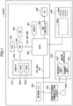
- FIG. 1 is diagram illustrating a hardware configuration of an information processing device according to the embodiment.
- the information processing device is, for example, a multifunction device called a multifunction peripheral/printer/product (MFP), that is, a device having an image processing function and a communication function, such as a facsimile, a scanner, a copy, and a printer.
- MFP multifunction peripheral/printer/product
- the MFP 9 includes a controller 910, a short distance communication circuit 920, an engine controller 930, an operation panel 940, and a network I/F 950.
- the controller 910 includes a CPU 901, a system memory (MEM-P) 902, a north bridge (NB) 903, a south bridge (SB) 904, an application specific integrated circuit (ASIC) 906, which are a main part of a computer, a local memory (MEM-C) 907, which is a storage unit, an HDD controller 908, and an HD 909, which is a storage unit, and the NB 903 is connected to the ASIC 906 through an accelerated graphics port (AGP) bus 921.
- AGP accelerated graphics port
- the CPU 901 is a controller that entirely controls the MFP 9.
- the NB 903 is a bridge that connects the CPU 901 to the MEM-P 902, the SB 904, and the AGP bus 921, and includes a memory controller that controls reading data from and writing data to the MEM-P 902, a peripheral component interconnect (PCI) master, and an AGP target.
- PCI peripheral component interconnect
- the MEM-P 902 includes a ROM 902a, which is a memory storing programs and data that achieve each function of the controller 910, and a RAM 902b, which is used to deploy programs or data and used as a drawing memory for printing from a memory.
- the programs stored in the RAM 902b may be recorded and provided in a computer-readable recording medium, such as a CD-ROM, a CD-R, or a DVD in a file in an installable format or an executable format.
- the SB 904 is a bridge that connects the NB 903 to PCI devices and peripheral devices.
- the ASIC 906 is an integrated circuit (IC), for image processing applications, having hardware elements for image processing, and serves as a bridge that connects to the AGP bus 921, a PCI bus 922, the HDD controller 908, and an MEM-C 907.
- the ASIC 906 includes a PCI target and an AGP master, an arbiter (ARB) that is the core of the ASIC 906, a memory controller that controls the MEM-C 907, multiple direct memory access controllers (DMACs) that rotate image data and the like by using hardware logic and the like, and a PCI unit that transfers data between the scanner unit 931 and the printer unit 932 through the PCI bus 922.
- the interface of the universal serial bus (USB) or the institute of electronic and electronic engineers 1394 (IEEE 1394) may be connected to the ASIC 906.
- the MEM-C 907 is a local memory used as an image buffer and a code buffer for copying.
- the HD 909 is a storage device that stores image data, stores font data used for printing, and stores forms.
- the HD 909 controls reading data from or writing data to the HD 909 based on the control of the CPU 901.
- the AGP bus 921 is a bus interface for graphics accelerator cards that is proposed to speed up graphics processing, and by directly accessing the MEM-P 902 with high throughput, the graphics accelerator card can speed up.
- the short distance communication circuit 920 is provided with a short distance communication circuit 920a.
- the short distance communication circuit 920 is a communication circuit such as NFC, Bluetooth, or the like.
- the engine controller 930 includes a scanner unit 931 and a printer unit 932.
- the operation panel 940 includes a panel display unit 940a (hereinafter, referred to as a "touch panel 940a") such as a touch panel that displays a current setting value, a selection screen, or the like, and that receives an input from an operator, and an operation panel 940b including a ten key that receives a setting value of a condition related to image forming, such as a density setting condition, a start key that receives a copy start instruction, and the like.
- the controller 910 entirely controls the MFP 9 and controls, for example, drawing, communication, input from the operation panel 940, and the like.
- the scanner unit 931 or the printer unit 932 includes a unit of image processing, such as for error diffusion or gamma conversion.
- an application switching key of the operation panel 940 allows the MFP 9 to sequentially switch between a document box function, a copy function, a printer function, and a facsimile function to be selected.
- the MFP 9 switches to a document box mode
- the MFP 9 switches to a printer mode
- the facsimile function is selected, the MFP 9 switches to a facsimile mode.
- the network I/F 950 is an interface for performing data communication by using a communication network.
- the short distance communication circuit 920 and the network I/F 950 are electrically connected to the ASIC 906 through a PCI bus 922.
- FIG. 2 is a schematic drawing of a display image layer of a touch panel 940a.
- the touch panel 940a has a three-layer structure in which a standard layer 10, a disable layer 20, and an interrupt layer 30 are overlapped and laminated.
- the lamination direction of the layers may be other than the vertical direction illustrated in FIG. 2 .
- the standard layer 10 is a display device that displays an operation screen provided for normal use of the touch panel 940a (including a home screen 11 illustrated in FIG. 5 , a touch disable function setting screen 14 illustrated in FIG. 7 , and the like).
- the disable layer 20 is a display device that displays a touch operation disable screen 21 (see FIG. 8 or other drawings) while the touch operation of the touch panel 940a is disabled.
- the disable layer 20 is positioned on the standard layer 10 and allows the touch operation disable screen 21 to be superimposed on the operation screen.
- the interrupt layer 30 is a display device that displays a notification screen 31 (see FIG. 9 ) that notifies an interrupt event when the interrupt event occurs while the touch operation is disabled.
- the interrupt layer 30 is positioned between the standard layer 10 and the disable layer 20.
- a liquid crystal display may be applied to the standard layer 10, for example.
- a transmissive liquid crystal display may be applied to the disable layer 20 and the interrupt layer 30, for example.
- FIG. 3 is a functional block diagram of the MFP 9 according to the embodiment.
- the controller 910 of the MFP 9 includes a disable controller 911, a drawing controller 912, and an interrupt controller 913.
- the disable controller 911 executes a mode (i.e., a touch disable mode) in which the operation input of the touch panel 940a is disabled.
- a mode i.e., a touch disable mode
- the touch disable mode is executed, for example, in response to receiving an instruction input from a user through the touch panel 940a.
- the disable controller 911 transmits a command indicating the execution of the touch disable mode to the drawing controller 912.
- the drawing controller 912 controls the display of each layer of the touch panel 940a (i.e., the standard layer 10, the disable layer 20, and the interrupt layer 30).
- the interrupt controller 913 performs control when an interrupt event, such as error detection in any one of the functions of the MFP 9, occurs while the touch operation is disabled.
- an interrupt event such as error detection in any one of the functions of the MFP 9
- the interrupt controller 913 transmits, to the drawing controller 912, a command to notify a user by displaying a notice indicating the interrupt event on the touch panel 940a.
- Each function of the controller 910 of the MFP 9 illustrated in FIG. 3 is achieved by operating various hardware under the control of the CPU 901, and reading and writing data in the RAM 902b by loading predetermined computer software (i.e., a touch panel display program) on hardware such as the CPU 901 and the RAM 902b of the controller 910. That is, when the touch panel display program of the MFP 9 according to the present embodiment is executed on a computer, the controller 910 of the MFP 9 functions as the disable controller 911, the drawing controller 912, and the interrupt controller 913 of FIG. 3 .
- predetermined computer software i.e., a touch panel display program
- FIG. 4 is a flowchart illustrating the setting of the touch disable mode.
- step S1 a touch disable application is started from the home screen 11 displayed in the standard layer 10.
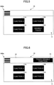
- FIG. 5 is a drawing illustrating an example of the home screen 11 including a touch disable function.
- the home screen 11 displays one or more icons (in FIG. 5 , four icons 11A to 11D) for starting one or more applications installed in the MFP 9.
- the function of the touch disable mode is provided as one application.
- the icon 11D of the touch disable application is disposed on the home screen 11 in a manner substantially same as the icons 11A to 11C of other function applications.
- a touch disable mode setting can be started by touching the icon 11D when the home screen 11 is displayed.
- FIG. 6 is a drawing illustrating another example of the home screen 11 including the touch disable function.
- a button 13 for starting the touch disable mode is disposed in a banner portion 12 at the upper portion of the home screen 11.
- the banner portion 12 is always displayed on the standard layer 10 even if the home screen 11 is not displayed on the standard layer 10.
- the touch disable mode setting can be started even when another application is started and the home screen 11 is not displayed, in addition to when the home screen 11 is displayed.
- a command to start the touch disable mode may be placed in a menu displayed by pressing a "setting button" typically provided on the device operation panel.
- step S2 a method for canceling the touch disable mode and the like are set in the displayed touch disable function setting screen 14.
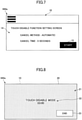
- FIG. 7 is a drawing illustrating an example of the touch disable function setting screen 14.
- the touch disable function setting screen 14 is displayed in the standard layer 10 in response to the operation in step S1.
- an item of a method of canceling the touch disable mode is displayed in the touch disable function setting screen 14.
- the cancel method may include "automatic" with a time limit or “manual” with a specific operation such as pressing a cancel button for an extended period of time. A user may select from one or both of them.
- the time and the like may be set depending on the cancel method. In the example of FIG. 7 , if "automatic" is selected as the cancel method, the time required to cancel the touch disable mode (i.e., cancel time) is set to "5 seconds".
- step S3 the touch disable mode is started by pushing a start button 15 of the touch disable function setting screen 14.
- the start button 15 is disposed at the lower right of the touch disable function setting screen 14, and the touch disable mode is automatically canceled when 5 seconds has passed after the start of the touch disable mode.
- the touch disable mode is canceled in response to the touch operation performed on an end button 23 displayed on the touch operation disable screen 21 of the disable layer 20.
- the screen When the touch disable mode is canceled, for example, the screen returns to the touch disable function setting screen 14. Subsequently, the screen may return to the home screen 11 by performing a normal operation of the operation panel, or another application may be started.
- FIG. 8 is a drawing illustrating a display example of the disable layer 20.
- the display of each layer of the touch panel 940a exemplified in FIG. 8 and FIG. 9 is controlled by the drawing controller 912.
- the touch operation disable screen 21 is displayed on the disable layer 20, as illustrated in FIG. 8 .
- the touch operation disable screen 21 is superimposed on the operation screen of the home screen 11 or the like displayed on the standard layer 10 and is displayed to hide the operation screen.
- the end button 23 is provided on the touch operation disable screen 21.
- the touch disable mode is terminated.
- the touch panel 940a is configured not to respond in a case where an area other than the end button 23 is touched.
- a display indicating a touch disable state or a countdown display 22 indicating the time for which the touch disable state continues may be provided.
- the touch operation performed on the end button 23 can be disabled with conditions by not responding to an operation performed on the end button 23 other than a specific operation such as a long press.
- FIG. 9 is a drawing illustrating a display example of the interrupt layer 30.
- the interrupt layer 30 displays, for example, the notification screen 31 for notifying the interrupt event, as illustrated in FIG. 9 .
- a message such as "Error has occurred. Please check it.” is displayed on the notification screen 31.
- the drawing controller 912 displays the notification screen 31 on the interrupt layer 30 based on a command transmitted to the drawing controller 912 when the interrupt controller 913 detects the interrupt event.
- the notification screen 31 is drawn on the home screen 11 of the standard layer 10 and under the touch operation disable screen 21 of the disable layer 20.
- a function in which an operation cannot be performed on a screen displayed under the touch operation disable screen 21 when the touch operation disable screen 21 is displayed, is provided.
- the notification screen 31 is necessarily displayed under the touch operation disable screen 21. Therefore, when the touch operation disable screen 21 and the notification screen 31 are simultaneously displayed, if an operation is input on the notification screen 31, the operation is not accepted by using the above-described function. Consequently, an incorrect operation performed on the notification screen 31 displaying an error can be prevented.
- FIG. 10 is a drawing illustrating another example of the interrupt layer 30.
- a message such as "Error has occurred. Do you want to cancel printing?" is displayed on the notification screen 31, and buttons 32 for inputting an operation of whether to cancel printing or not are displayed.
- the above-described effect of preventing an incorrect operation performed on the notification screen 31 is particularly effective when any input function such as the buttons 32 (in addition to the buttons 32, a button for closing the display because the error content has been confirmed) are displayed on the notification screen 31, as illustrated in FIG. 10 .
- the display of the notification screen 31 illustrated in FIG. 10 prevents the user from operating the buttons 32 without checking the error message. This kind of situation can happen, for example, when wiping the panel by using the disable mode.
- the notification screen 31 is superimposed on a standard screen (e.g., the home screen 11) of the standard layer 10 and is displayed to hide the standard screen. Further, when the notification screen 31 is displayed, the display mode of the touch operation disable screen 21 is changed to be semi-transparent (or transparent). Therefore, the notification screen 31 can be viewed by the user while the standard screen is hidden.
- a standard screen e.g., the home screen 11
- the display mode of the touch operation disable screen 21 is changed to be semi-transparent (or transparent). Therefore, the notification screen 31 can be viewed by the user while the standard screen is hidden.
- the user who has confirmed the error notification on the notification screen 31 can cancel the touch disable mode by performing an operation such as pressing the end button 23 for an extended period of time, and can check the error notification and perform an operation to solve the error.
- the MFP 9 includes the standard layer 10 that displays an operation screen provided for normal use of the touch panel 940a (such as the home screen 11), a disable layer 20 provided to overlap the standard layer 10, an interrupt layer 30 provided to overlap the standard layer 10 and the disable layer 20, a disable controller 911 that disables the touch operation of the touch panel 940a, and a drawing controller 912 that displays the touch operation disable screen 21 on the disable layer 20 to superimpose the touch operation disable screen 21 on the operation screen in a case where the touch operation is disabled by the disable controller 911.
- the drawing controller 912 displays the notification screen 31 that notifies an interrupt event on the interrupt layer 30 when an interrupt event has occurred while the touch operation is disabled.
- the notification screen 31 on the interrupt layer 30 can be displayed to notify a user that the event has occurred, while the touch operation disable screen 21 on the disable layer 20 is displayed to maintain the disable mode. Consequently, the MFP 9 according to the present embodiment can display the interrupt notification during the disable mode of the touch panel 940a and can maintain the disable mode.
- processing circuit includes a processor programmed to perform each function with software, such as a processor implemented by electronic circuits, and a device designed to perform each function described above, such as an application specific integrated circuit (ASIC), a digital signal processor (DSP), a field programmable gate array (FPGA), and a conventional circuit module.
- ASIC application specific integrated circuit
- DSP digital signal processor
- FPGA field programmable gate array
- the information processing device is not limited to the MFP as long as the device includes an element equivalent to the touch panel 940a.
- the information processing device may be, for example, a projector (PJ), an interactive white board (IWB) (i.e., a white board having a function of an electronic chalkboard that can perform mutual communication), an output device such as a digital signage, a head up display (HUD) device, an industrial machine, an imaging device, a sound collecting device, a medical device, a network home appliance, a connected car, a personal computer, a mobile phone, a smartphone, a tablet terminal, a game console, a personal digital assistant (PDA), a digital camera, a wearable PC, or a desktop PC.
- PJ projector
- IWB interactive white board
- HUD head up display
- an industrial machine such as a digital signage, a head up display (HUD) device, an industrial machine, an imaging device, a sound collecting device, a medical device, a network home appliance, a connected
- a configuration, in which the interrupt layer 30 is positioned between the standard layer 10 and the disable layer 20, is exemplified, but at least a configuration, in which the standard layer 10, the disable layer 20, and the interrupt layer 30 are laminated, is required, and the interrupt layer 30 may be positioned on the disable layer 20.
Landscapes
- Engineering & Computer Science (AREA)
- Multimedia (AREA)
- Signal Processing (AREA)
- Theoretical Computer Science (AREA)
- General Engineering & Computer Science (AREA)
- Human Computer Interaction (AREA)
- Physics & Mathematics (AREA)
- General Physics & Mathematics (AREA)
- Health & Medical Sciences (AREA)
- General Health & Medical Sciences (AREA)
- Biomedical Technology (AREA)
- Microelectronics & Electronic Packaging (AREA)
- User Interface Of Digital Computer (AREA)
- Accessory Devices And Overall Control Thereof (AREA)
- Facsimiles In General (AREA)
- Controls And Circuits For Display Device (AREA)
Abstract
Description
- The present disclosure relates to an information processing device, a touch panel display method, and a touch panel display program.
- In an information processing device such as an MFP, a configuration, in which an operation command is input through a touch panel mounted to the device, is known.
-
Patent Document 1 describes a configuration in which, in response to receiving an input from an operation disable information display unit on the touch panel, an input of the touch panel is disabled for a predetermined time period. - In the conventional method of disabling the operation of the touch panel such as
Patent Document 1, when an error occurs in a main device during a touch disable mode, an error and notification cannot be displayed, and there may be a case where the operation does not progress. Additionally, if an error or the like is displayed by interruption, an error screen may overwrite a disable state, and the disable state may be canceled at an unexpected timing, so that an error operation may be caused. - It is an object of the present disclosure to enable an interrupt notification to be displayed during the disable mode of the touch panel and to enable the disable mode to be maintained.
- Patent Document 1:
Japanese Patent No. 4378999 - According to one aspect of an embodiment, an information processing device includes a standard layer configured to display an operation screen provided for use of a touch panel, a disable layer provided to overlap the standard layer, an interrupt layer provided to overlap the standard layer and the disable layer, a disable controller configured to disable a touch operation of the touch panel, and a drawing controller configured to display a touch operation disable screen on the disable layer to superimpose the touch operation disable screen on the operation screen, in a case where the touch operation is disabled by the disable controller. The drawing controller displays, when an interrupt event has occurred while the touch operation is disabled, a notification screen on the interrupt layer, the notification screen notifying the interrupt event.
- According to at least one embodiment of the present disclosure, the interrupt notification can be displayed during the disable mode of the touch panel, and the disable mode can be maintained.
-
-
FIG. 1 is a diagram illustrating a hardware configuration of an information processing device according to an embodiment; -
FIG. 2 is a schematic diagram illustrating display image layers of a touch panel; -
FIG. 3 is a block diagram illustrating functions of the information processing device according to the embodiment; -
FIG. 4 is a flow chart of setting a touch disable mode; -
FIG. 5 is a drawing illustrating an example of a home screen including a touch disabling function; -
FIG. 6 is a drawing illustrating another example of the home screen including the touch disabling function; -
FIG. 7 is a drawing illustrating an example of a touch disabling setting screen; -
FIG. 8 is a drawing illustrating a display example of a disable layer; -
FIG. 9 is a drawing illustrating a display example of an interrupt layer; and -
FIG. 10 is a drawing illustrating another display example of the interrupt layer. - In the following, an embodiment will be described with reference to the accompanying drawings. In order to facilitate the understanding of the description, the same components in each drawing are referenced by the same reference numeral, as far as possible, and the overlapping description is omitted.
-
FIG. 1 is diagram illustrating a hardware configuration of an information processing device according to the embodiment. - The information processing device is, for example, a multifunction device called a multifunction peripheral/printer/product (MFP), that is, a device having an image processing function and a communication function, such as a facsimile, a scanner, a copy, and a printer. Hereinafter, the MFP will be described as an example of the information processing device.
- As illustrated in
FIG. 1 , the MFP 9 includes acontroller 910, a shortdistance communication circuit 920, anengine controller 930, anoperation panel 940, and a network I/F 950. - Among these, the
controller 910 includes aCPU 901, a system memory (MEM-P) 902, a north bridge (NB) 903, a south bridge (SB) 904, an application specific integrated circuit (ASIC) 906, which are a main part of a computer, a local memory (MEM-C) 907, which is a storage unit, anHDD controller 908, and anHD 909, which is a storage unit, and theNB 903 is connected to the ASIC 906 through an accelerated graphics port (AGP) bus 921. - Among these, the
CPU 901 is a controller that entirely controls theMFP 9. TheNB 903 is a bridge that connects theCPU 901 to the MEM-P 902, theSB 904, and the AGP bus 921, and includes a memory controller that controls reading data from and writing data to the MEM-P 902, a peripheral component interconnect (PCI) master, and an AGP target. - The MEM-
P 902 includes aROM 902a, which is a memory storing programs and data that achieve each function of thecontroller 910, and aRAM 902b, which is used to deploy programs or data and used as a drawing memory for printing from a memory. The programs stored in theRAM 902b may be recorded and provided in a computer-readable recording medium, such as a CD-ROM, a CD-R, or a DVD in a file in an installable format or an executable format. - The SB 904 is a bridge that connects the
NB 903 to PCI devices and peripheral devices. The ASIC 906 is an integrated circuit (IC), for image processing applications, having hardware elements for image processing, and serves as a bridge that connects to the AGP bus 921, a PCI bus 922, theHDD controller 908, and an MEM-C 907. The ASIC 906 includes a PCI target and an AGP master, an arbiter (ARB) that is the core of the ASIC 906, a memory controller that controls the MEM-C 907, multiple direct memory access controllers (DMACs) that rotate image data and the like by using hardware logic and the like, and a PCI unit that transfers data between thescanner unit 931 and theprinter unit 932 through the PCI bus 922. The interface of the universal serial bus (USB) or the institute of electronic and electronic engineers 1394 (IEEE 1394) may be connected to the ASIC 906. - The MEM-
C 907 is a local memory used as an image buffer and a code buffer for copying. TheHD 909 is a storage device that stores image data, stores font data used for printing, and stores forms. TheHD 909 controls reading data from or writing data to theHD 909 based on the control of theCPU 901. The AGP bus 921 is a bus interface for graphics accelerator cards that is proposed to speed up graphics processing, and by directly accessing the MEM-P 902 with high throughput, the graphics accelerator card can speed up. - The short
distance communication circuit 920 is provided with a shortdistance communication circuit 920a. The shortdistance communication circuit 920 is a communication circuit such as NFC, Bluetooth, or the like. - The
engine controller 930 includes ascanner unit 931 and aprinter unit 932. Theoperation panel 940 includes apanel display unit 940a (hereinafter, referred to as a "touch panel 940a") such as a touch panel that displays a current setting value, a selection screen, or the like, and that receives an input from an operator, and anoperation panel 940b including a ten key that receives a setting value of a condition related to image forming, such as a density setting condition, a start key that receives a copy start instruction, and the like. Thecontroller 910 entirely controls theMFP 9 and controls, for example, drawing, communication, input from theoperation panel 940, and the like. Thescanner unit 931 or theprinter unit 932 includes a unit of image processing, such as for error diffusion or gamma conversion. - Here, an application switching key of the
operation panel 940 allows theMFP 9 to sequentially switch between a document box function, a copy function, a printer function, and a facsimile function to be selected. When the document box function is selected, theMFP 9 switches to a document box mode, when the copy function is selected, theMFP 9 switches to a printer mode, and when the facsimile function is selected, theMFP 9 switches to a facsimile mode. - The network I/F 950 is an interface for performing data communication by using a communication network. The short
distance communication circuit 920 and the network I/F 950 are electrically connected to the ASIC 906 through a PCI bus 922. -
FIG. 2 is a schematic drawing of a display image layer of atouch panel 940a. - As illustrated in
FIG. 2 , in the present embodiment, thetouch panel 940a has a three-layer structure in which astandard layer 10, adisable layer 20, and aninterrupt layer 30 are overlapped and laminated. The lamination direction of the layers may be other than the vertical direction illustrated inFIG. 2 . - The
standard layer 10 is a display device that displays an operation screen provided for normal use of thetouch panel 940a (including ahome screen 11 illustrated inFIG. 5 , a touch disablefunction setting screen 14 illustrated inFIG. 7 , and the like). - The
disable layer 20 is a display device that displays a touch operation disable screen 21 (seeFIG. 8 or other drawings) while the touch operation of thetouch panel 940a is disabled. Thedisable layer 20 is positioned on thestandard layer 10 and allows the touch operation disablescreen 21 to be superimposed on the operation screen. - The interrupt
layer 30 is a display device that displays a notification screen 31 (seeFIG. 9 ) that notifies an interrupt event when the interrupt event occurs while the touch operation is disabled. The interruptlayer 30 is positioned between thestandard layer 10 and the disablelayer 20. - A liquid crystal display (LCD) may be applied to the
standard layer 10, for example. A transmissive liquid crystal display may be applied to the disablelayer 20 and the interruptlayer 30, for example. -
FIG. 3 is a functional block diagram of theMFP 9 according to the embodiment. - As illustrated in
FIG. 3 , thecontroller 910 of theMFP 9 includes a disablecontroller 911, adrawing controller 912, and an interruptcontroller 913. - The disable
controller 911 executes a mode (i.e., a touch disable mode) in which the operation input of thetouch panel 940a is disabled. In the touch disable mode, a normal operation input performed by a user using thetouch panel 940a is not reflected in the operation of theMFP 9. The touch disable mode is executed, for example, in response to receiving an instruction input from a user through thetouch panel 940a. When executing the touch disable mode, the disablecontroller 911 transmits a command indicating the execution of the touch disable mode to thedrawing controller 912. - The drawing
controller 912 controls the display of each layer of thetouch panel 940a (i.e., thestandard layer 10, the disablelayer 20, and the interrupt layer 30). - The interrupt
controller 913 performs control when an interrupt event, such as error detection in any one of the functions of theMFP 9, occurs while the touch operation is disabled. When the interrupt event is detected, for example, the interruptcontroller 913 transmits, to thedrawing controller 912, a command to notify a user by displaying a notice indicating the interrupt event on thetouch panel 940a. - Each function of the
controller 910 of theMFP 9 illustrated inFIG. 3 is achieved by operating various hardware under the control of theCPU 901, and reading and writing data in theRAM 902b by loading predetermined computer software (i.e., a touch panel display program) on hardware such as theCPU 901 and theRAM 902b of thecontroller 910. That is, when the touch panel display program of theMFP 9 according to the present embodiment is executed on a computer, thecontroller 910 of theMFP 9 functions as the disablecontroller 911, the drawingcontroller 912, and the interruptcontroller 913 ofFIG. 3 . - Referring to
FIGs. 4 to 7 , a method of setting the touch disable mode will be described.FIG. 4 is a flowchart illustrating the setting of the touch disable mode. - In step S1, a touch disable application is started from the
home screen 11 displayed in thestandard layer 10. -
FIG. 5 is a drawing illustrating an example of thehome screen 11 including a touch disable function. Thehome screen 11 displays one or more icons (inFIG. 5 , fouricons 11A to 11D) for starting one or more applications installed in theMFP 9. In the example ofFIG. 5 , the function of the touch disable mode is provided as one application. In this case, theicon 11D of the touch disable application is disposed on thehome screen 11 in a manner substantially same as theicons 11A to 11C of other function applications. In the example ofFIG. 5 , a touch disable mode setting can be started by touching theicon 11D when thehome screen 11 is displayed. -
FIG. 6 is a drawing illustrating another example of thehome screen 11 including the touch disable function. In the example ofFIG. 6 , abutton 13 for starting the touch disable mode is disposed in abanner portion 12 at the upper portion of thehome screen 11. When an application other than the touch disable mode is started, thebanner portion 12 is always displayed on thestandard layer 10 even if thehome screen 11 is not displayed on thestandard layer 10. Thus, in the example ofFIG. 6 , the touch disable mode setting can be started even when another application is started and thehome screen 11 is not displayed, in addition to when thehome screen 11 is displayed. - In the examples illustrated in
FIG. 5 and FIG. 6 , a command to start the touch disable mode may be placed in a menu displayed by pressing a "setting button" typically provided on the device operation panel. - Returning to
FIG. 4 , in step S2, a method for canceling the touch disable mode and the like are set in the displayed touch disablefunction setting screen 14. -
FIG. 7 is a drawing illustrating an example of the touch disablefunction setting screen 14. The touch disablefunction setting screen 14 is displayed in thestandard layer 10 in response to the operation in step S1. - In the example of
FIG. 7 , an item of a method of canceling the touch disable mode is displayed in the touch disablefunction setting screen 14. The cancel method may include "automatic" with a time limit or "manual" with a specific operation such as pressing a cancel button for an extended period of time. A user may select from one or both of them. In addition, the time and the like may be set depending on the cancel method. In the example ofFIG. 7 , if "automatic" is selected as the cancel method, the time required to cancel the touch disable mode (i.e., cancel time) is set to "5 seconds". - In step S3, the touch disable mode is started by pushing a
start button 15 of the touch disablefunction setting screen 14. - In the example of
FIG. 7 , thestart button 15 is disposed at the lower right of the touch disablefunction setting screen 14, and the touch disable mode is automatically canceled when 5 seconds has passed after the start of the touch disable mode. When "manual" is selected as the cancel method in the touch disablefunction setting screen 14 ofFIG. 7 , for example, the touch disable mode is canceled in response to the touch operation performed on anend button 23 displayed on the touch operation disablescreen 21 of the disablelayer 20. - When the touch disable mode is canceled, for example, the screen returns to the touch disable
function setting screen 14. Subsequently, the screen may return to thehome screen 11 by performing a normal operation of the operation panel, or another application may be started. - Referring to
FIG. 8 andFIG. 9 , a screen example of the touch panel in the touch disable mode will be described.FIG. 8 is a drawing illustrating a display example of the disablelayer 20. The display of each layer of thetouch panel 940a exemplified inFIG. 8 andFIG. 9 is controlled by the drawingcontroller 912. - When the touch disable mode is started, the touch operation disable
screen 21 is displayed on the disablelayer 20, as illustrated inFIG. 8 . The touch operation disablescreen 21 is superimposed on the operation screen of thehome screen 11 or the like displayed on thestandard layer 10 and is displayed to hide the operation screen. - The
end button 23 is provided on the touch operation disablescreen 21. When theend button 23 is touched, the touch disable mode is terminated. In the touch operation disablescreen 21, thetouch panel 940a is configured not to respond in a case where an area other than theend button 23 is touched. Additionally, on the touch operation disablescreen 21, a display indicating a touch disable state or acountdown display 22 indicating the time for which the touch disable state continues may be provided. - Further, the touch operation performed on the
end button 23 can be disabled with conditions by not responding to an operation performed on theend button 23 other than a specific operation such as a long press. -
FIG. 9 is a drawing illustrating a display example of the interruptlayer 30. When an interrupt event such as an error of any element in theMFP 9 occurs during the touch disable mode, the interruptlayer 30 displays, for example, thenotification screen 31 for notifying the interrupt event, as illustrated inFIG. 9 . For example, a message such as "Error has occurred. Please check it." is displayed on thenotification screen 31. The drawingcontroller 912 displays thenotification screen 31 on the interruptlayer 30 based on a command transmitted to thedrawing controller 912 when the interruptcontroller 913 detects the interrupt event. - As described above, because the interrupt
layer 30 is positioned between thestandard layer 10 and the disablelayer 20, thenotification screen 31 is drawn on thehome screen 11 of thestandard layer 10 and under the touch operation disablescreen 21 of the disablelayer 20. According to the present embodiment, a function, in which an operation cannot be performed on a screen displayed under the touch operation disablescreen 21 when the touch operation disablescreen 21 is displayed, is provided. With the above-described lamination structure, thenotification screen 31 is necessarily displayed under the touch operation disablescreen 21. Therefore, when the touch operation disablescreen 21 and thenotification screen 31 are simultaneously displayed, if an operation is input on thenotification screen 31, the operation is not accepted by using the above-described function. Consequently, an incorrect operation performed on thenotification screen 31 displaying an error can be prevented. -
FIG. 10 is a drawing illustrating another example of the interruptlayer 30. InFIG. 10 , for example, a message such as "Error has occurred. Do you want to cancel printing?" is displayed on thenotification screen 31, andbuttons 32 for inputting an operation of whether to cancel printing or not are displayed. The above-described effect of preventing an incorrect operation performed on thenotification screen 31 is particularly effective when any input function such as the buttons 32 (in addition to thebuttons 32, a button for closing the display because the error content has been confirmed) are displayed on thenotification screen 31, as illustrated inFIG. 10 . The display of thenotification screen 31 illustrated inFIG. 10 prevents the user from operating thebuttons 32 without checking the error message. This kind of situation can happen, for example, when wiping the panel by using the disable mode. - As with the touch operation disable
screen 21 illustrated inFIG. 8 , thenotification screen 31 is superimposed on a standard screen (e.g., the home screen 11) of thestandard layer 10 and is displayed to hide the standard screen. Further, when thenotification screen 31 is displayed, the display mode of the touch operation disablescreen 21 is changed to be semi-transparent (or transparent). Therefore, thenotification screen 31 can be viewed by the user while the standard screen is hidden. - The user who has confirmed the error notification on the
notification screen 31 can cancel the touch disable mode by performing an operation such as pressing theend button 23 for an extended period of time, and can check the error notification and perform an operation to solve the error. - As described above, the
MFP 9 according to the present embodiment includes thestandard layer 10 that displays an operation screen provided for normal use of thetouch panel 940a (such as the home screen 11), a disablelayer 20 provided to overlap thestandard layer 10, an interruptlayer 30 provided to overlap thestandard layer 10 and the disablelayer 20, a disablecontroller 911 that disables the touch operation of thetouch panel 940a, and adrawing controller 912 that displays the touch operation disablescreen 21 on the disablelayer 20 to superimpose the touch operation disablescreen 21 on the operation screen in a case where the touch operation is disabled by the disablecontroller 911. The drawingcontroller 912 displays thenotification screen 31 that notifies an interrupt event on the interruptlayer 30 when an interrupt event has occurred while the touch operation is disabled. - With this configuration, when an interrupt event such as an error is detected during the execution of the touch disable mode, the
notification screen 31 on the interruptlayer 30 can be displayed to notify a user that the event has occurred, while the touch operation disablescreen 21 on the disablelayer 20 is displayed to maintain the disable mode. Consequently, theMFP 9 according to the present embodiment can display the interrupt notification during the disable mode of thetouch panel 940a and can maintain the disable mode. - Each function of the embodiment described above may be implemented by one or more processing circuits. Here, a "processing circuit" in the present specification includes a processor programmed to perform each function with software, such as a processor implemented by electronic circuits, and a device designed to perform each function described above, such as an application specific integrated circuit (ASIC), a digital signal processor (DSP), a field programmable gate array (FPGA), and a conventional circuit module.
- Although the
MFP 9 is exemplified as the information processing device according to the above-described embodiment, the information processing device is not limited to the MFP as long as the device includes an element equivalent to thetouch panel 940a. The information processing device may be, for example, a projector (PJ), an interactive white board (IWB) (i.e., a white board having a function of an electronic chalkboard that can perform mutual communication), an output device such as a digital signage, a head up display (HUD) device, an industrial machine, an imaging device, a sound collecting device, a medical device, a network home appliance, a connected car, a personal computer, a mobile phone, a smartphone, a tablet terminal, a game console, a personal digital assistant (PDA), a digital camera, a wearable PC, or a desktop PC. - The embodiment has been described above with reference to the specific examples. However, the present disclosure is not limited to the specific examples. Examples, in which design modifications have been appropriately made to these examples by those skilled in the art, are also included in the present disclosure as long as the examples have the features of the present disclosure. Each element provided in the specific examples described above, and the arrangement, conditions, shape, and the like thereof, are not limited to those exemplified, and may be appropriately modified. A combination of the elements provided in the specific examples may be appropriately changed, unless there is a technical inconsistency.
- In the above embodiment, a configuration, in which the interrupt
layer 30 is positioned between thestandard layer 10 and the disablelayer 20, is exemplified, but at least a configuration, in which thestandard layer 10, the disablelayer 20, and the interruptlayer 30 are laminated, is required, and the interruptlayer 30 may be positioned on the disablelayer 20.
Claims (4)
- An information processing device comprising:a standard layer configured to display an operation screen provided for use of a touch panel;a disable layer provided to overlap the standard layer;an interrupt layer provided to overlap the standard layer and the disable layer;a disable controller configured to disable a touch operation of the touch panel; anda drawing controller configured to display a touch operation disable screen on the disable layer to superimpose the touch operation disable screen on the operation screen, in a case where the touch operation is disabled by the disable controller,wherein the drawing controller displays, when an interrupt event has occurred while the touch operation is disabled, a notification screen on the interrupt layer, the notification screen notifying the interrupt event.
- The information processing device as claimed in claim 1,wherein the interrupt layer is provided between the standard layer and the disable layer, andwherein the drawing controller changes the touch operation disable screen on the disable layer to be transparent or semitransparent when displaying the notification screen on the interrupt layer.
- A touch panel display method comprising:disabling a touch operation of a touch panel;displaying, in a case where the touch operation is disabled, a touch operation disable screen on a disable layer to superimpose the touch operation disable screen on an operation screen provided for use of the touch panel, the disable layer being provided to overlap a standard layer, and the standard layer displaying the operation screen; anddisplaying, when an interrupt event has occurred while the touch operation is disabled, a notification screen on an interrupt layer, the interrupt layer being provided to overlap the standard layer and the disable layer, and the notification screen notifying the interrupt event.
- A touch panel display program for causing a computer to perform:disabling a touch operation of a touch panel;displaying, in a case where the touch operation is disabled, a touch operation disable screen on a disable layer to superimpose the touch operation disable screen on an operation screen provided for use of the touch panel, the disable layer being provided to overlap a standard layer, and the standard layer displaying the operation screen; anddisplaying, when an interrupt event has occurred while the touch operation is disabled, a notification screen on an interrupt layer, the interrupt layer being provided to overlap the standard layer and the disable layer, and the notification screen notifying the interrupt event.
Applications Claiming Priority (1)
| Application Number | Priority Date | Filing Date | Title |
|---|---|---|---|
| JP2020132640A JP7635514B2 (en) | 2020-08-04 | 2020-08-04 | Information processing device, touch panel display method, and touch panel display program |
Publications (1)
| Publication Number | Publication Date |
|---|---|
| EP3951580A1 true EP3951580A1 (en) | 2022-02-09 |
Family
ID=77411522
Family Applications (1)
| Application Number | Title | Priority Date | Filing Date |
|---|---|---|---|
| EP21188541.3A Withdrawn EP3951580A1 (en) | 2020-08-04 | 2021-07-29 | Information processing device, touch panel display method, and touch panel display program |
Country Status (3)
| Country | Link |
|---|---|
| US (1) | US11445074B2 (en) |
| EP (1) | EP3951580A1 (en) |
| JP (1) | JP7635514B2 (en) |
Citations (3)
| Publication number | Priority date | Publication date | Assignee | Title |
|---|---|---|---|---|
| JP4378999B2 (en) | 2003-05-27 | 2009-12-09 | パナソニック株式会社 | Information terminal device and water heater remote control device applying the device to a water heater |
| US20100302173A1 (en) * | 2009-05-28 | 2010-12-02 | Xerox Corporation | Multi-layer display |
| US20140191970A1 (en) * | 2013-01-10 | 2014-07-10 | Pantech Co., Ltd. | Terminal to set a touch lock layer, and method thereof |
Family Cites Families (8)
| Publication number | Priority date | Publication date | Assignee | Title |
|---|---|---|---|---|
| JPS5024397B1 (en) | 1970-04-08 | 1975-08-15 | ||
| JPS5834834B2 (en) | 1972-06-26 | 1983-07-29 | オリエンタルシヤシンコウギヨウ カブシキガイシヤ | How to get a successful card |
| JP2000207092A (en) | 1999-01-19 | 2000-07-28 | Internatl Business Mach Corp <Ibm> | Method and device for preventing misoperation and storage medium with software product for misoperation prevention stored therein |
| WO2001015132A1 (en) * | 1999-08-19 | 2001-03-01 | Deep Video Imaging Limited | Control of depth movement for visual display with layered screens |
| JP4531356B2 (en) | 2003-06-26 | 2010-08-25 | 株式会社メガチップス | Image display device and image display switching method |
| JP5024397B2 (en) | 2010-01-29 | 2012-09-12 | ブラザー工業株式会社 | Input device and input control program |
| JP5834834B2 (en) | 2011-11-29 | 2015-12-24 | 株式会社リコー | Display system and program |
| US10592188B2 (en) | 2016-12-28 | 2020-03-17 | Pure Death Limited | Content bumping in multi-layer display systems |
-
2020
- 2020-08-04 JP JP2020132640A patent/JP7635514B2/en active Active
-
2021
- 2021-07-29 EP EP21188541.3A patent/EP3951580A1/en not_active Withdrawn
- 2021-07-29 US US17/443,966 patent/US11445074B2/en active Active
Patent Citations (3)
| Publication number | Priority date | Publication date | Assignee | Title |
|---|---|---|---|---|
| JP4378999B2 (en) | 2003-05-27 | 2009-12-09 | パナソニック株式会社 | Information terminal device and water heater remote control device applying the device to a water heater |
| US20100302173A1 (en) * | 2009-05-28 | 2010-12-02 | Xerox Corporation | Multi-layer display |
| US20140191970A1 (en) * | 2013-01-10 | 2014-07-10 | Pantech Co., Ltd. | Terminal to set a touch lock layer, and method thereof |
Also Published As
| Publication number | Publication date |
|---|---|
| US20220046134A1 (en) | 2022-02-10 |
| JP2022029342A (en) | 2022-02-17 |
| JP7635514B2 (en) | 2025-02-26 |
| US11445074B2 (en) | 2022-09-13 |
Similar Documents
| Publication | Publication Date | Title |
|---|---|---|
| US20190373120A1 (en) | Information processing apparatus and non-transitory computer readable medium | |
| US10705680B2 (en) | Information processing apparatus and non-transitory computer readable medium | |
| US11630565B2 (en) | Image processing apparatus, control method for image processing apparatus, and recording medium for displaying a screen with inverted colors | |
| US10582072B2 (en) | Information processing apparatus and non-transitory computer readable medium comprising a display screen including basic operator for execution of certain function | |
| CN110851037A (en) | Information processing apparatus and recording medium | |
| US8154760B2 (en) | Image forming apparatus, content display method, and computer program product | |
| US8982397B2 (en) | Image processing device, non-transitory computer readable recording medium and operational event determining method | |
| US11445074B2 (en) | Information processing device, touch panel display method, and recording medium | |
| US9875014B2 (en) | Input apparatus and storage medium storing input control program | |
| CN107786768B (en) | Information processing apparatus, image forming apparatus, and information processing method | |
| US11269680B2 (en) | Information processing apparatus, information processing system, and information processing method | |
| JP6719732B2 (en) | Electronics and systems | |
| US20240134510A1 (en) | Information processing device and program | |
| US10509507B2 (en) | Display device, information processing apparatus, method for controlling display device, and storage medium | |
| US20250211690A1 (en) | Information processing system and non-transitory computer-readable recording medium | |
| US20240281130A1 (en) | Information processing apparatus, control method, and storage medium | |
| US20240231730A9 (en) | Information processing device and program | |
| CN113949778B (en) | Information processing apparatus, information processing method and computer-readable medium | |
| US20250165126A1 (en) | Information processing system, non-transitory computer readable medium and information processing method | |
| US20240283874A1 (en) | Information processing apparatus, information processing system, information processing method, and recording medium | |
| JP7334452B2 (en) | User support system | |
| JP2025099114A (en) | electronic equipment | |
| JP2023035686A (en) | Information processing device, information processing method, and program | |
| JP2022016905A (en) | Information processing equipment and programs | |
| JP2017054396A (en) | Information processing apparatus having touch panel, control method of information processing apparatus, and program |
Legal Events
| Date | Code | Title | Description |
|---|---|---|---|
| PUAI | Public reference made under article 153(3) epc to a published international application that has entered the european phase |
Free format text: ORIGINAL CODE: 0009012 |
|
| STAA | Information on the status of an ep patent application or granted ep patent |
Free format text: STATUS: REQUEST FOR EXAMINATION WAS MADE |
|
| 17P | Request for examination filed |
Effective date: 20210729 |
|
| AK | Designated contracting states |
Kind code of ref document: A1 Designated state(s): AL AT BE BG CH CY CZ DE DK EE ES FI FR GB GR HR HU IE IS IT LI LT LU LV MC MK MT NL NO PL PT RO RS SE SI SK SM TR |
|
| STAA | Information on the status of an ep patent application or granted ep patent |
Free format text: STATUS: EXAMINATION IS IN PROGRESS |
|
| 17Q | First examination report despatched |
Effective date: 20231124 |
|
| STAA | Information on the status of an ep patent application or granted ep patent |
Free format text: STATUS: THE APPLICATION IS DEEMED TO BE WITHDRAWN |
|
| 18D | Application deemed to be withdrawn |
Effective date: 20240326 |