EP3951554A1 - Display device - Google Patents
Display device Download PDFInfo
- Publication number
- EP3951554A1 EP3951554A1 EP21189222.9A EP21189222A EP3951554A1 EP 3951554 A1 EP3951554 A1 EP 3951554A1 EP 21189222 A EP21189222 A EP 21189222A EP 3951554 A1 EP3951554 A1 EP 3951554A1
- Authority
- EP
- European Patent Office
- Prior art keywords
- folding area
- display device
- folding
- disposed
- metal plate
- Prior art date
- Legal status (The legal status is an assumption and is not a legal conclusion. Google has not performed a legal analysis and makes no representation as to the accuracy of the status listed.)
- Granted
Links
Images






Classifications
-
- G—PHYSICS
- G09—EDUCATION; CRYPTOGRAPHY; DISPLAY; ADVERTISING; SEALS
- G09F—DISPLAYING; ADVERTISING; SIGNS; LABELS OR NAME-PLATES; SEALS
- G09F9/00—Indicating arrangements for variable information in which the information is built-up on a support by selection or combination of individual elements
- G09F9/30—Indicating arrangements for variable information in which the information is built-up on a support by selection or combination of individual elements in which the desired character or characters are formed by combining individual elements
- G09F9/301—Indicating arrangements for variable information in which the information is built-up on a support by selection or combination of individual elements in which the desired character or characters are formed by combining individual elements flexible foldable or roll-able electronic displays, e.g. thin LCD, OLED
-
- G—PHYSICS
- G06—COMPUTING OR CALCULATING; COUNTING
- G06F—ELECTRIC DIGITAL DATA PROCESSING
- G06F1/00—Details not covered by groups G06F3/00 - G06F13/00 and G06F21/00
- G06F1/16—Constructional details or arrangements
- G06F1/1613—Constructional details or arrangements for portable computers
- G06F1/1615—Constructional details or arrangements for portable computers with several enclosures having relative motions, each enclosure supporting at least one I/O or computing function
- G06F1/1616—Constructional details or arrangements for portable computers with several enclosures having relative motions, each enclosure supporting at least one I/O or computing function with folding flat displays, e.g. laptop computers or notebooks having a clamshell configuration, with body parts pivoting to an open position around an axis parallel to the plane they define in closed position
-
- G—PHYSICS
- G06—COMPUTING OR CALCULATING; COUNTING
- G06F—ELECTRIC DIGITAL DATA PROCESSING
- G06F1/00—Details not covered by groups G06F3/00 - G06F13/00 and G06F21/00
- G06F1/16—Constructional details or arrangements
- G06F1/1613—Constructional details or arrangements for portable computers
- G06F1/1615—Constructional details or arrangements for portable computers with several enclosures having relative motions, each enclosure supporting at least one I/O or computing function
- G06F1/1616—Constructional details or arrangements for portable computers with several enclosures having relative motions, each enclosure supporting at least one I/O or computing function with folding flat displays, e.g. laptop computers or notebooks having a clamshell configuration, with body parts pivoting to an open position around an axis parallel to the plane they define in closed position
- G06F1/1618—Constructional details or arrangements for portable computers with several enclosures having relative motions, each enclosure supporting at least one I/O or computing function with folding flat displays, e.g. laptop computers or notebooks having a clamshell configuration, with body parts pivoting to an open position around an axis parallel to the plane they define in closed position the display being foldable up to the back of the other housing with a single degree of freedom, e.g. by 360° rotation over the axis defined by the rear edge of the base enclosure
-
- G—PHYSICS
- G06—COMPUTING OR CALCULATING; COUNTING
- G06F—ELECTRIC DIGITAL DATA PROCESSING
- G06F1/00—Details not covered by groups G06F3/00 - G06F13/00 and G06F21/00
- G06F1/16—Constructional details or arrangements
- G06F1/1613—Constructional details or arrangements for portable computers
- G06F1/1633—Constructional details or arrangements of portable computers not specific to the type of enclosures covered by groups G06F1/1615 - G06F1/1626
- G06F1/1637—Details related to the display arrangement, including those related to the mounting of the display in the housing
- G06F1/1652—Details related to the display arrangement, including those related to the mounting of the display in the housing the display being flexible, e.g. mimicking a sheet of paper, or rollable
-
- G—PHYSICS
- G06—COMPUTING OR CALCULATING; COUNTING
- G06F—ELECTRIC DIGITAL DATA PROCESSING
- G06F1/00—Details not covered by groups G06F3/00 - G06F13/00 and G06F21/00
- G06F1/16—Constructional details or arrangements
- G06F1/1613—Constructional details or arrangements for portable computers
- G06F1/1633—Constructional details or arrangements of portable computers not specific to the type of enclosures covered by groups G06F1/1615 - G06F1/1626
- G06F1/1675—Miscellaneous details related to the relative movement between the different enclosures or enclosure parts
- G06F1/1681—Details related solely to hinges
-
- G—PHYSICS
- G06—COMPUTING OR CALCULATING; COUNTING
- G06F—ELECTRIC DIGITAL DATA PROCESSING
- G06F2203/00—Indexing scheme relating to G06F3/00 - G06F3/048
- G06F2203/041—Indexing scheme relating to G06F3/041 - G06F3/045
- G06F2203/04102—Flexible digitiser, i.e. constructional details for allowing the whole digitising part of a device to be flexed or rolled like a sheet of paper
Definitions
- the disclosure relates to a display device, and more specifically, to a display device capable of switching a state between a folded state and an unfolded state.
- a display device displays an image.
- the market share of display devices having the same or a smaller volume or thickness and a larger display screen than those of the conventional display devices has increased.
- a flexible display device such as a foldable display device or a bendable display device has been developed, which has a structure that can be folded and unfolded to provide a larger screen when desired.
- the foldable display devices may include, on the basis of a display screen, an in-foldable display device in which the display screen is folded inward, and an out-foldable display device in which the display screen is folded outward.
- a foldable display device may be an in-foldable display device or an out-foldable display device, but is not limited thereto, and may be an in/out-foldable display device capable of both in-folding and out-folding.
- aspects of the disclosure provide an in/out-foldable display device capable of both in-folding and out-folding.
- a display device may include a display module including a first folding area extending in a first direction, a first non-folding area located on a first side of the first folding area in a second direction intersecting the first direction, a second non-folding area located on a second side of the first folding area in the second direction, a second folding area extending in the second direction, a third non-folding area located on a first side of the second folding area in the first direction, and a fourth non-folding area located on a second side of the second folding area in the first direction, wherein the display module may include a first surface and a second surface opposite to the first surface, the first surface being a display surface, and in an out-folding operation state, the display device is folded with respect to the second folding area such that the second surface in the third non-folding area and the second surface in the fourth non-folding area face each other.
- the display device may further include a metal plate disposed on, preferably directly on the second surface of the display module.
- the display device may be folded with respect to the first folding area such that the first surface in the first non-folding area and the first surface in the second non-folding area face each other.
- the metal plate may include a first metal plate disposed in an overlapping manner in the first non-folding area and the third non-folding area; a second metal plate disposed in an overlapping manner in the second non-folding area and the third non-folding area; a third metal plate disposed in an overlapping manner in the first non-folding area and the fourth non-folding area; and a fourth metal plate disposed in an overlapping manner in the second non-folding area and the fourth non-folding area.
- Each of the first metal plate to the fourth metal plate may have a whole pattern.
- the metal plate may include a fifth metal plate disposed in the second folding area and disposed between the third non-folding area and the fourth non-folding area in the first non-folding area; and a sixth metal plate disposed between the third non-folding area and the fourth non-folding area in the second non-folding area.
- Each of the fifth metal plate and the sixth metal plate may include a plurality of first patterns extending in the second direction and arranged in the first direction.
- Each of the fifth metal plate and the sixth metal plate may not be disposed in the first folding area.
- the metal plate may include a seventh metal plate disposed in an intersection region of the first folding area and the second folding area or disposed in a portion of the first folding area which does not overlap the second folding area, the seventh metal plate may include a plurality of second patterns separated from the first to sixth metal plates adjacent thereto.
- the display device may further include a main plate disposed under the metal plate.
- the main plate may include a first main plate disposed in an overlapping manner in the first non-folding area and the third non-folding area; a second main plate disposed in an overlapping manner in the second non-folding area and the third non-folding area; a third main plate disposed in an overlapping manner in the first non-folding area and the fourth non-folding area; and a fourth main plate disposed in an overlapping manner in the second non-folding area and the fourth non-folding area.
- the display device may further comprise a first gear unit disposed in a portion of the second folding area which does not overlap the first folding area.
- the first gear unit may include an extension part extending in the second direction, and at least one joint part extending in the first direction from the extension part.
- the at least one joint part may include a plurality of joint parts, and the plurality of joint parts may be disposed in the main plate and overlaps the main plate.
- An overlap length of the main plate and the at least one joint part in an unfolded state of the display device may be greater than an overlap length of the main plate and the at least one joint part in the out-folding operation state of the display device.
- the display device may further comprise a second gear unit disposed along the first folding area.
- the second gear unit may be configured and used to perform an in-folding operation of the display device.
- the first gear unit may be configured and used to perform an out-folding operation of the display device.
- a display device capable of an in-folding operation and an out-folding operation may comprise a display module including a first folding area extending in a first direction, a first non-folding area located on, preferably directly on a first side of the first folding area in a second direction crossing the first direction, a second non-folding area located on, preferably directly on a second side of the first folding area in the second direction, a second folding area extending in the second direction, a third non-folding area located on, preferably directly on a first side of the second folding area in the first direction, and a fourth non-folding area located on, preferably directly on a second side of the second folding area in the first direction, and a first surface and a second surface opposite to the first surface, the first surface being a display surface; and a metal plate disposed on, preferably directly on the second surface of the display module.
- One of the first folding area and the second folding area is a folding area for the in-folding operation
- the other one of the first folding area and the second folding area is a folding area for the out-folding operation.
- the metal plate is disposed in one of the first folding area and the second folding area and is not disposed in the other one of the first folding area and the second folding area.
- the first folding area may be a folding area for the in-folding operation
- the second folding area may be a folding area for the out-folding operation
- the first surfaces in each of the first and second non-folding areas may face each other with respect to the first folding area
- the second surfaces in each of the third and fourth non-folding areas may face each other with respect to the second folding area.
- the display device may further comprise a gear unit for the out-folding operation disposed in the second folding area.
- the gear unit for the out-folding operation may include an extension part extending in the second direction; and a joint part extending in the first direction from the extension part.
- a cross-sectional shape of the joint part may include a circle having a predetermined curvature.
- the display device may be out-folded according to the curvature of the joint part.
- relative terms such as “lower” or “bottom” and “upper” or “top,” may be used herein to describe one element's relationship to another element as illustrated in the Figures. It will be understood that relative terms are intended to encompass different orientations of the device in addition to the orientation depicted in the Figures. For example, if the device in one of the figures is turned over, elements described as being on the “lower” side of other elements would then be oriented on “upper” sides of the other elements. The term “lower,” can therefore, encompasses both an orientation of “lower” and “upper,” depending on the particular orientation of the figure.
- Embodiments are described herein with reference to cross section illustrations that are schematic illustrations of idealized embodiments. As such, variations from the shapes of the illustrations as a result, for example, of manufacturing techniques and/or tolerances, are to be expected. Thus, embodiments described herein should not be construed as being limited to the particular shapes of regions as illustrated herein but are to include deviations in shapes that result, for example, from manufacturing. For example, a region illustrated or described as being flat may, typically, have rough and/or nonlinear features. Moreover, sharp angles that are illustrated may be rounded. Thus, the regions illustrated in the figures are schematic in nature and their shapes are not intended to illustrate the precise shape of a region and are not intended to limit the scope of the present claims.
- FIG. 1 is a schematic perspective view of a display device according to an embodiment.
- a display device 1 may be a foldable display device.
- foldable may include bendable, rollable, and the like. Further, the term “foldable” should be interpreted as including “partially foldable,” “entirely foldable,” “in-foldable,” and “out-foldable.”
- the display device 1 may include an in-foldable display device and an out-foldable display device.
- the display device 1 may be a display device capable of in-folding (see “INFOLDING” of FIG. 2 ) to be in an in-folding operation state and of out-folding (see “OUTFOLDING” of FIG. 3 ) to be in an out-folding operation state.
- the in-folding operation state may indicate an operation state in which the display device 1 is folded such that the display surfaces face each other
- the out-folding operation state may indicate an operation state in which the display device 1 is folded such that the display surface faces outward (such that the other surfaces opposite to the display surfaces face each other).
- the in-folding operation state may be referred to as a first operation state
- the out-folding operation state may be referred to as a second operation state.
- a first direction DR1, a second direction DR2, and a third direction DR3 may intersect each other in different directions.
- the horizontal direction, the vertical direction, and the thickness direction of the display device 1 may be respectively defined as the first direction DR1, the second direction DR2, and the third direction DR3.
- the first direction DR1 includes a rightward direction with respect to the display device 1 in perspective view and a leftward direction with respect to the display device 1 in perspective view.
- the second direction DR2 includes an upward direction with respect to the display device 1 in perspective view and a downward direction with respect to the display device 1 in perspective view.
- the third direction DR3 includes a direction toward the display surface from the other surface of the display device 1 and a direction toward the other surface from the display surface of the display device 1. It should be understood, however, that a direction mentioned in the embodiment refers to a relative direction and the embodiment is not limited to the direction mentioned.
- the display device 1 may have a rectangular shape in a plan view.
- the display device 1 may include long sides LS1 and LS2 extending in the first direction DR1 and short sides SS1 and SS2 extending in the second direction DR2 in a plan view.
- the first long side LS1 of the display device 1 may be located at one side of the display device 1 in the second direction DR2, and the second long side LS2 thereof may be located at the other side of the display device 1 in the second direction DR2.
- the first short side SS1 of the display device 1 may be located at one side of the display device 1 in the first direction DR1, and the second short side SS2 thereof may be located at the other side of the display device 1 in the first direction DR1.
- the display device 1 may be a foldable display device capable of in-folding or out-folding to be in the first operation state or the second operation state, respectively.
- the display device 1 may be in the first operation state or the second operation state with respect to a folding area defined in the display device 1.
- a first folding area FA1 for the first operation state and a second folding area FA2 for the second operation state may be defined in the display device 1.
- the first folding area FA1 may extend in the second direction DR2, and the second folding area FA2 may extend in the first direction DR1.
- the first folding area FA1 may be formed to traverse an area from the first long side LS1 to the second long side LS2 of the display device 1
- the second folding area FA2 may be formed to traverse an area from the first short side SS1 to the second short side SS2 of the display device 1.
- the first folding area FA1 and the second folding area FA2 may intersect each other.
- the first folding area FA1 and the second folding area FA2 may be disposed to overlap, preferably fully overlap each other at the intersection.
- the first folding area FA1 and the second folding area FA2 may not overlap each other outside the intersection of the first folding area FA1 and the second folding area FA2.
- the first folding area FA1 may be located between the center portions of the first and second long sides LS1 and LS2 of the display device 1.
- Non-folding areas NFA1 and NFA2 may be further defined in the display device 1 with respect to the first folding area FA1 located between the center portions of the first and second long sides LS1 and LS2 of the display device 1.
- the first non-folding area NFA1 may be located on the other side of the first folding area FA1in the first direction DR1 and the second non-folding area NFA2 may be located on one side of the first folding area FA1 in the first direction DR1.
- the first non-folding area NFA1 may be disposed to overlap, preferably fully overlap the third non-folding area NFA3, the fourth non-folding area NFA4, and the second folding area FA2 positioned on the other side of the first folding area FA1 in the first direction DR1, and the second non-folding area NFA2 may be disposed to overlap, preferably fully overlap the third non-folding area NFA3, the fourth non-folding area NFA4, and the second folding area FA2 positioned on one side of the first folding area FA1 in the first direction DR1.
- the third non-folding area NFA3 may be disposed to overlap, preferably fully overlap the first non-folding area NFA1, the second non-folding area NFA2, and the first folding area FA1 positioned on one side of the second folding area FA2 in the second direction DR2
- the fourth non-folding area NFA4 may be disposed to overlap, preferably fully overlap the first non-folding area NFA1, the second non-folding area NFA2, and the first folding area FA1 positioned on the other side of the second folding area FA2 in the second direction DR2.
- the display device 1 may include a display module 100 (see FIG. 4 ), as will be described below.
- the display module 100 may include a display surface that displays an image and the other surface that is opposite to the display surface.
- the display surface and the other surface of the display module 100 may be opposite to each other.
- the display device 1 In the first operation state of the display device 1, the display device 1 may be folded such that the display surfaces of the display module 100 face each other, and in the second operation state, the display device 1 may be folded such that the other surfaces of the display module 100 face each other.
- the first operation state and the second operation state of the display device 1 will be described in detail with reference to FIGS. 2 and 3 .
- FIG. 2 is a schematic perspective view illustrating a first operation state of a display device according to an embodiment.
- FIG. 3 is a schematic perspective view illustrating a second operation state of a display device according to an embodiment.
- the display device 1 in the first operation state of the display device 1, the display device 1 may be folded such that the display surfaces of the display module 100 face each other, and in the second operation state, the display device 1 may be folded such that the other surfaces of the display module 100 face each other.
- the display device 1 may be folded with respect to the first folding area FA1 such that the display surfaces of the first non-folding area NFA1 and the second non-folding area NFA2 face each other.
- the display device 1 may be folded with respect to the second folding area FA2 such that the other surfaces of the third non-folding area NFA3 and the fourth non-folding area NFA4 face each other.
- the first operation state and the second operation state of the display device 1 may be achieved through a gear unit provided in each of the first and second folding areas FA1 and FA2 of the display device 1. A more detailed description will be given with reference to FIG. 4 .
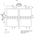
- FIG. 4 is a schematic plan view of a display device according to an embodiment.
- the display device 1 may include a display module 100.
- the display module 100 may have a shape similar to that of the display device 1 described above.
- the display module 100 may include a display panel.
- the display panel may be an organic light emitting display panel, a liquid crystal display panel, a plasma display panel, an electrophoretic display panel, an electrowetting display panel, a quantum dot light emitting display panel, a micro light emitting diode (LED) display panel, a nano LED display panel, or the like.
- an organic light emitting display panel may be used as the display panel.
- the display panel may include a flexible substrate including a flexible polymer material such as polyimide (PI). Accordingly, the display panel 100 may be curved, bent, folded, or rolled.
- the display panel may include pixels.
- the pixels of the display panel may be located in the center portion of the display panel.
- the display panel may further include driving circuits or signal lines for applying signals to the pixels.
- the signal lines and driving circuits may be located in the edge portion of the display panel.
- the pixel may include a light emitting layer and a circuit layer for controlling the amount of light emitted from the light emitting layer.
- the circuit layer may include wirings, electrodes, and at least one transistor.
- the light emitting layer may include an organic light emitting material.
- the light emitting layer may be sealed by an encapsulation layer.
- the encapsulation layer may seal the light emitting layer to prevent moisture or the like from infiltrating from the outside.
- the encapsulation layer may be a single or multilayer inorganic film, or a laminated film formed by alternately laminating inorganic and organic films.
- a window may be further disposed on, preferably directly on the display module 100 to protect the display module 100.
- the window may be disposed to overlap, preferably fully overlap the display panel in the thickness direction.
- the window and the display panel may have substantially the same size in a plan view.
- the window may be made of glass, quartz, or the like.
- the window may have a thickness less than about 100 ⁇ m, preferably less than about 95 ⁇ m or less than 90 ⁇ m.
- the window may include ultra-thin glass (UTG).
- the window may include a flexible material.
- the display module 100 may be disposed over the first and second folding areas FA1 and FA2 and the first to fourth non-folding areas NFA1 to NFA4.
- the display device 1 may further include a metal plate 200 disposed below, preferably directly below the display module 100.
- the metal plate 200 may prevent the display module 100 from being bent or may reduce the degree to which the display module 100 is bent (e.g., bending angle, or bending curvature radius) by an external force. For example, the metal plate 200 may maintain the display module 100 in a relatively flat state even in case that an external force is applied thereto.
- the metal plate 200 may include a rigid or semi-rigid material.
- the metal plate 200 may include a metal material such as stainless steel (SUS) and aluminum, or a polymer such as polymethyl methacrylate (PMMA), polycarbonate (PC), polyvinyl alcohol (PVA), acrylonitrile-butadiene-styrene (ABS), polyethylene terephthalate (PET), or the like.
- the metal plate 200 may be a stainless steel film having a thickness of about 150 ⁇ m to about 200 ⁇ m, preferably of about 155 ⁇ m to about 195 ⁇ m or about 160 ⁇ m to about 190 ⁇ m.
- the metal plate 200 may be an aluminum film having a thickness of about 150 ⁇ m to about 200 ⁇ m,preferably of about 155 ⁇ m to about 195 ⁇ m or about 160 ⁇ m to about 190 ⁇ m.
- the metal plate 200 may include first to sixth metal plates 210, 220, 230, 240, 250, and 260.
- the first metal plate 210 may be disposed in a region where the first non-folding area NFA1 and the third non-folding area NFA3 overlap, preferably fully overlap each other
- the second metal plate 220 may be disposed in a region where the second non-folding area NFA2 and the third non-folding area NFA3 overlap, preferably fully overlap each other
- the third metal plate 230 may be disposed in a region where the first non-folding area NFA1 and the fourth non-folding area NFA4 overlap, preferably fully overlap each other
- the fourth metal plate 240 may be disposed in a region where the second non-folding area NFA2 and the fourth non-folding area NFA4 overlap, preferably fully overlap each other.
- the fifth metal plate 250 may be disposed in a region of the second folding area FA2, which overlaps, preferably fully overlap the first non-folding area NFA1
- the sixth metal plate 260 may be disposed in a region of the second folding area FA2, which overlaps, preferably fully overlaps the second non-folding area NFA2.
- the fifth metal plate 250 may be disposed between the first metal plate 210 and the third metal plate 230 in a plan view
- the sixth metal plate 260 may be disposed between the second metal plate 220 and the fourth metal plate 240 in a plan view.
- Each of the first to fourth metal plates 210, 220, 230, and 240 may have a shape of a whole pattern.
- the first metal plate 210 and the second metal plate 220 may be physically separated from each other, and the third metal plate 230 and the fourth metal plate 240 may be physically separated from each other.
- each of the fifth metal plate 250 and the sixth metal plate 260 may include patterns extending in the first direction DR1.
- the respective patterns of the fifth metal plate 250 and the sixth metal plate 260 may be disposed to be spaced apart from each other in the second direction DR2.
- the fifth metal plate 250 and the sixth metal plate 260 may be disposed to be spaced apart from each other while interposing therebetween a second gear unit 410 located in the first folding area FA1, which will be described below.
- Each of the metal plates 210, 220, 230, and 240 of the display device 1 may be formed as the whole pattern, thereby supporting the upper display module 100 in their positions.
- each of the fifth and sixth metal plates 250 and 260 of the display device 1 may be formed as the multiple patterns, and thus may more readily achieve the second operation state of the display device 1, as will be described below.
- the metal plate 200 of the display device 1 may not be provided in the first folding area FA1. Accordingly, in case that the display device 1 is switched from a non-folding state to the first operation state, it is possible to prevent stress caused by the metal plate 200.
- the display device 1 may further include a main plate 300 disposed under, preferably directly under the metal plate 200.
- a first main plate 310 may be disposed in a region where the first non-folding area NFA1 and the third non-folding area NFA3 overlap, preferably fully overlap each other
- a second main plate 320 may be disposed in a region where the second non-folding area NFA2 and the third non-folding area NFA3 overlap, preferably fully overlap each other
- a third main plate 330 may be disposed in a region where the first non-folding area NFA1 and the fourth non-folding area NFA4 overlap, preferably fully overlap each other
- a fourth main plate 340 may be disposed in a region where the second non-folding area NFA2 and the fourth non-folding area NFA4 overlap, preferably fully overlap each other.
- the first to fourth main plates 310, 320, 330, and 340 may be physically spaced apart from each other.
- the first operation state and the second operation state of the display device 1 may be achieved through the gear unit provided in each of the first and second folding areas FA1 and FA2 of the display device 1.
- the display device 1 may further include gear units 400 (including 410 and 450) disposed in the first and second folding areas FA1 and FA2, respectively.
- the second gear unit 410 may be disposed in the first folding area FA1, and the first gear unit 450 may be disposed in the second folding area FA2.
- the second gear unit 410 may extend in the second direction DR2, which is the extension direction of the first folding area FA1, and the first gear unit 450 may extend in the first direction DR1, which is the extension direction of the second folding area FA2.
- the second gear unit 410 may be configured to switch the display device 1 from the non-folding state to the first operation state
- the first gear unit 450 may be configured to switch the display device 1 from the non-folding state to the second operation state.
- each gear unit 410 or 450 A detailed configuration of each gear unit 410 or 450 will be described with reference to FIGS. 5 to 9 .
- FIG. 5 is a schematic enlarged side view of area A of FIG. 2 .
- FIG. 6 is a schematic enlarged plan view of area B of FIG. 4 .
- FIG. 7 is a schematic enlarged side view of the sixth metal plate and the display module of FIG. 5 .
- the second gear unit 410 may include a first joint part 411, a connection part 413, a shaft 415, and a main gear 417.
- the first joint part 411 may be connected to, preferably directly to the adjacent connection part 413.
- the first joint part 411 may include an upper joint part disposed to overlap, preferably fully overlap the first and third metal plates 210 and 230 in a side view and a lower joint part disposed to overlap, preferably fully overlap the second and fourth metal plates 220 and 240 in a side view.
- the upper and lower joint parts may be separated from each other in the thickness direction.
- Multiple first joint parts 411 may be provided.
- the connection part 413 may be disposed between the adjacent first joint parts 411.
- the connection part 413 may be connected with, preferably directly with the adjacent first joint part 411.
- the connection parts 413 may be disposed to overlap, preferably fully overlap the first to fourth metal plates 210, 220, 230, and 240 in a side view.
- the shaft 415 may extend in the second direction DR2. Multiple shafts may be provided.
- the shafts 415 may be located below the sixth metal plate 260 and above the fifth metal plate 250 in a side view.
- the shaft 415 may pass through the first joint part 411 and the connection part 413.
- the shafts 415 may be located on the left and right sides of the main gear 417 and may extend to be connected to, preferably directly to the main gear 417 in a side view.
- the first gear unit 450 may include an extension part 451 extending in the first direction DR1, and second joint parts 455 branched from the extension part 451.
- the second joint parts 455 may be disposed in the adjacent main plate 300 and overlap, preferably fully overlap the adjacent main plate 300.
- the second joint parts 455 located above the second folding area FA2 and on the left side of the first folding area FA1 may be disposed in the first main plate 310 and overlap, preferably fully overlap the first main plate 310
- the second joint parts 455 located above the second folding area FA2 and on the right side of the first folding area FA1 may be disposed in the second main plate 320 and overlap, preferably fully overlap the second main plate 320
- the second joint parts 455 located under, preferably directly under the second folding area FA2 and on the left side of the first folding area FA1 may be disposed in the third main plate 330 and overlap, preferably fully overlap the third main plate 330
- the second joint parts 455 located under the second folding area FA2 and on the right side of the first folding area FA1 may be disposed in the fourth main plate 340 and overlap, preferably fully overlap the fourth main plate 340.
- FIG. 4 illustrates that the number of the second joint parts 455 overlapping, preferably fully overlapping each of the first to fourth main plates 310, 320, 330, and 340 is 5, but the number of the second joint parts 455 overlapping, preferably fully overlapp each of the first to fourth main plates 310, 320, 330, and 340 is not limited to 5 and may be less than or greater than 5.
- FIGS. 8 and 9 are schematic diagrams illustrating a second folding operation of a display device according to an embodiment.
- the second joint parts 455 may be disposed in the adjacent main plate 300 and overlap, preferably fully overlap the adjacent main plate 300.
- the second joint parts 455 located above, preferably directly above the second folding area FA2 and on the left side of the first folding area FA1 may be disposed in the first main plate 310 and overlap the first main plate 310
- the second joint parts 455 located above, preferably directly above the second folding area FA2 and on the right side of the first folding area FA1 may be disposed in the second main plate 320 and overlap, preferably fully overlap the second main plate 320
- the second joint parts 455 located under, preferably directly under the second folding area FA2 and on the left side of the first folding area FA1 may be disposed in the third main plate 330 and overlap, preferably fully overlap the third main plate 330
- the second joint parts 455 located under the second folding area FA2 and on the right side of the first folding area FA1 may be disposed in the fourth main plate 340 and overlap, preferably fully overlap the fourth main plate 340.
- each of the first to fourth main plates 310, 320, 330, and 340 and the second joint part 455 may be disposed to overlap, preferably fully overlap each other while having a first overlap length L1.
- the other surface of the display module 100 may be subjected to compressive stress, and the display surface of the display module 100 may be subjected to tensile stress. If the compressive stress is applied to the other surface of the display module 100 when the display device 1 switches to the second operation state, the length of the other surface of the display module 100 adjacent to, preferably directly to the second joint parts 455 may be shortened. If the second joint parts 455 are connected to, preferably directly to the adjacent first and third main plates 310 and 330, the length of the other surface of the display module 100 may be maintained despite the tendency that the length of the other surface of the display module 100 becomes shortened. Therefore, waviness may occur on the other surface of the display module 100. This may be visually recognized by a user and cause a screen defect. However, the present invention is not limited thereto.
- first and third main plates 310 and 330 and the second joint parts 455 are disconnected to allow the second joint parts 455 to be further moved into the first and third main plates 310 and 330.
- the first and third main plates 310 and 330 and the second joint parts 455 may be disconnected such that the second joint parts 455 are further moved into the first and third main plates 310 and 330, thereby preventing the waviness from occurring on the other surface of the display module 100.
- the first overlap length L1 of the second joint parts 455 and the first and third main plates 310 and 330 may increase to a second overlap length L2.
- a portion of the second joint part 455, which is connected to, preferably directly to the extension part 451, may have a circular cross-sectional shape.
- the circular cross-sectional shape of the portion of the second joint part 455, which is connected to the extension part 451, may have a predetermined curvature.
- the display module 100 and the metal plate 200 may switch to the second operation state by the circular shape (having a predetermined curvature) of the portion of the second joint part 455 that is connected to, preferably directly to the extension part 451.
- each of the first to fourth metal plates 210, 220, 230, and 240 of the display device 1 may be formed as the whole pattern, thereby supporting the upper display module 100 in their positions.
- each of the fifth and sixth metal plates 250 and 260 of the display device 1 may be formed as multiple patterns, and thus may serve to more readily achieve the second operation state of the display device 1.
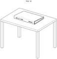
- FIG. 10 is a schematic perspective view showing a first operation state of a display device according to an embodiment.
- the display device 1 since the display device 1 according to an embodiment is capable of switching from the non-folding state to the first operation state, the user can easily see the screen of the display device 1 by folding only the upper portion (e.g., the first non-folding area NFA1 of FIG. 1 ) of the display device 1 after placing the display device 1 in a non-folding state on an arbitrary support.
- the upper portion e.g., the first non-folding area NFA1 of FIG. 1
- FIG. 11 is a schematic perspective view illustrating an example of a second operation state of a display device according to an embodiment.
- FIG. 12 is a schematic perspective view illustrating an example in which the display device of FIG. 11 is used.
- the user may see the image on an area including the folding area (e.g., second folding area FA2 of FIGS. 1 and 3 ) in the second operation state as well.
- the user may see the image displayed in the folding area (e.g., the second folding area FA2) after placing the display device 1 in the second operation state on a support.
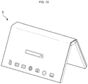
- FIG. 13 is a schematic perspective view illustrating another example of a second operation state of a display device according to an embodiment.
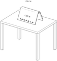
- FIG. 14 is a schematic perspective view illustrating another example in which the display device of FIG. 13 is used.
- each of the non-folding areas may display an image.
- the display device 1 is capable of switching from the non-folding state to the second operation state, so that an image may be displayed in each of the non-folding areas (e.g., the third and fourth non-folding areas NFA3 and NFA4 of FIGS. 1 and 3 ) and an arc shape may be formed by the non-folding areas and the folding area in a perspective view as shown in FIG. 13 , thereby showing or sharing the screen with a third person sitting on the opposite side.
- the non-folding areas e.g., the third and fourth non-folding areas NFA3 and NFA4 of FIGS. 1 and 3
- an arc shape may be formed by the non-folding areas and the folding area in a perspective view as shown in FIG. 13 , thereby showing or sharing the screen with a third person sitting on the opposite side.
- FIG. 15 is a schematic plan view of a display device according to another embodiment.
- FIG. 16 is a schematic enlarged plan view of area C of FIG. 15 .
- a display device 2 according to the embodiment may be different from the display device 1 of FIGS. 1 to 9 at least in that a metal plate 200_1 of the display device 2 further includes seventh and eighth metal plates 270 and 280.
- the metal plate 200_1 of the display device 2 may further include the seventh and eighth metal plates 270 and 280.
- the seventh and eighth metal plates 270 and 280 may be disposed in the first folding area FA1.
- the seventh metal plate 270 may be disposed on, preferably directly on one side of the second folding area FA2 in the second direction DR2
- the eighth metal plate 280 may be disposed on, preferably directly on the other side of the second folding area FA2 in the second direction DR2.
- the seventh metal plate 270 may include patterns.
- the patterns of the seventh metal plate 270 may be disposed to be spaced apart from each other.
- the patterns of the seventh metal plate 270 may be arranged in a matrix in the first direction DR1 and the second direction DR2.
- the disclosure is not limited thereto, and the patterns of the seventh metal plate 270 may be arranged in various ways.
- the pattern arrangement method of the eighth metal plate 280 and the pattern arrangement method of the seventh metal plate 270 may be substantially the same or different.
- the display device 2 may further include the seventh and eighth metal plates 270 and 280, and the display module 100 may be more effectively supported in the first folding area FA1. Accordingly, it is possible to prevent sagging of the display module 100 in the first folding area FA1.
- the other surface of the display module 100 when switching to the second operation state, the other surface of the display module 100 may be subjected to compressive stress, and the display surface of the display module 100 may be subjected to tensile stress. If the compressive stress is applied to the other surface of the display module 100 when the display device 2 switches to the second operation state, the length of the other surface of the display module 100 adjacent to the second joint parts 455 may tend to be shortened. If the second joint parts 455 are connected to the adjacent first and third main plates 310 and 330, the length of the other surface of the display module 100 may be maintained despite the tendency that the length of the other surface of the display module 100 becomes shortened. Therefore, waviness may occur on the other surface of the display module 100. This may be visually recognized by the user and may cause a screen defect.
- first and third main plates 310 and 330 and the second joint parts 455 are disconnected to allow the second joint parts 455 to be further moved into the first and third main plates 310 and 330.
- the first and third main plates 310 and 330 and the second joint parts 455 may be disconnected such that the second joint parts 455 are further moved into the first and third main plates 310 and 330, thereby preventing the waviness from occurring on the other surface of the display module 100.
- FIG. 17 is a schematic plan view showing a modified example of FIG. 16 .
- a display device may be different from the display device 2 of FIG. 16 at least in that a seventh metal plate 270_1 includes openings OP.
- the seventh metal plate 270_1 of the display device may include the multiple openings OP.
- the openings OP may include rows extending in the second direction DR2 as illustrated in FIG. 17 .
- the rows of the adjacent openings OP may be alternately disposed (or may be disposed in a zigzag manner).
- the openings OP may completely penetrate the seventh metal plate 270_1 in the thickness direction.
- the material of the seventh metal plate 270_1 may completely surround the openings OP.
- FIG. 18 is a schematic plan view of a display device according to still another embodiment.
- FIG. 19 is a schematic enlarged plan view of area D of FIG. 18 .
- a display device 3 may be different from the display device 1 of FIGS. 1 to 9 at least in that the display device 3 further includes a ninth metal plate 290 disposed in an overlapping area of the first folding area FA1 and the second folding area FA2.
- the display device 3 may further include the ninth metal plate 290 disposed in the overlapping area of the first folding area FA1 and the second folding area FA2.
- the ninth metal plate 290 may include patterns as shown in FIG. 19 .
- the patterns of the ninth metal plate 290 may be disposed to be spaced apart from each other.
- the patterns of the ninth metal plate 290 may be arranged in a matrix in the first direction DR1 and the second direction DR2.
- the disclosure is not limited thereto, and the patterns of the ninth metal plate 290 may be arranged in various ways.
- the display device 3 may further include the ninth metal plate 290, and the display module 100 may be more effectively supported in the overlapping area of the first folding area FA1 and the second folding area FA2. Accordingly, it is possible to prevent sagging of the display module 100 in the overlapping area of the first folding area FA1 and the second folding area FA2.
- the other surface of the display module 100 when the display device 3 switches to the second operation state, the other surface of the display module 100 may be subjected to compressive stress, and the display surface of the display module 100 may be subjected to tensile stress. If the compressive stress is applied to the other surface of the display module 100 when the display device 3 switches to the second operation state, the length of the other surface of the display module 100 adjacent to the second joint parts 455 may tend to be shortened. If the second joint parts 455 are connected to the adjacent first and third main plates 310 and 330, the length of the other surface of the display module 100 may be maintained despite the tendency that the length of the other surface of the display module 100 becomes shortened. Therefore, waviness may occur on the other surface of the display module 100. This may be visually recognized by the user and may cause a screen defect.
- first and third main plates 310 and 330 and the second joint parts 455 are disconnected to allow the second joint parts 455 to be further moved into the first and third main plates 310 and 330.
- the first and third main plates 310 and 330 and the second joint parts 455 may be disconnected such that the second joint parts 455 are further moved into the first and third main plates 310 and 330, thereby preventing the waviness from occurring on the other surface of the display module 100.
Landscapes
- Engineering & Computer Science (AREA)
- Theoretical Computer Science (AREA)
- Computer Hardware Design (AREA)
- Physics & Mathematics (AREA)
- General Physics & Mathematics (AREA)
- Human Computer Interaction (AREA)
- General Engineering & Computer Science (AREA)
- Mathematical Physics (AREA)
- Devices For Indicating Variable Information By Combining Individual Elements (AREA)
- Electroluminescent Light Sources (AREA)
Abstract
Description
- The disclosure relates to a display device, and more specifically, to a display device capable of switching a state between a folded state and an unfolded state.
- A display device displays an image. The market share of display devices having the same or a smaller volume or thickness and a larger display screen than those of the conventional display devices has increased. Further, a flexible display device such as a foldable display device or a bendable display device has been developed, which has a structure that can be folded and unfolded to provide a larger screen when desired.
- The foldable display devices may include, on the basis of a display screen, an in-foldable display device in which the display screen is folded inward, and an out-foldable display device in which the display screen is folded outward.
- A foldable display device may be an in-foldable display device or an out-foldable display device, but is not limited thereto, and may be an in/out-foldable display device capable of both in-folding and out-folding.
- Aspects of the disclosure provide an in/out-foldable display device capable of both in-folding and out-folding.
- However, aspects of the disclosure are not restricted to the one set forth herein. The above and other aspects of the disclosure will become more apparent to one of ordinary skill in the art to which the disclosure pertains by referencing the detailed description of the disclosure given below.
- According to an embodiment, a display device may include a display module including a first folding area extending in a first direction, a first non-folding area located on a first side of the first folding area in a second direction intersecting the first direction, a second non-folding area located on a second side of the first folding area in the second direction, a second folding area extending in the second direction, a third non-folding area located on a first side of the second folding area in the first direction, and a fourth non-folding area located on a second side of the second folding area in the first direction, wherein the display module may include a first surface and a second surface opposite to the first surface, the first surface being a display surface, and in an out-folding operation state, the display device is folded with respect to the second folding area such that the second surface in the third non-folding area and the second surface in the fourth non-folding area face each other.
- The display device may further include a metal plate disposed on, preferably directly on the second surface of the display module.
- In an in-folding operation state, the display device may be folded with respect to the first folding area such that the first surface in the first non-folding area and the first surface in the second non-folding area face each other.
- The metal plate may include a first metal plate disposed in an overlapping manner in the first non-folding area and the third non-folding area; a second metal plate disposed in an overlapping manner in the second non-folding area and the third non-folding area; a third metal plate disposed in an overlapping manner in the first non-folding area and the fourth non-folding area; and a fourth metal plate disposed in an overlapping manner in the second non-folding area and the fourth non-folding area. Each of the first metal plate to the fourth metal plate may have a whole pattern.
- The metal plate may include a fifth metal plate disposed in the second folding area and disposed between the third non-folding area and the fourth non-folding area in the first non-folding area; and a sixth metal plate disposed between the third non-folding area and the fourth non-folding area in the second non-folding area.
- Each of the fifth metal plate and the sixth metal plate may include a plurality of first patterns extending in the second direction and arranged in the first direction.
- Each of the fifth metal plate and the sixth metal plate may not be disposed in the first folding area.
- The metal plate may include a seventh metal plate disposed in an intersection region of the first folding area and the second folding area or disposed in a portion of the first folding area which does not overlap the second folding area, the seventh metal plate may include a plurality of second patterns separated from the first to sixth metal plates adjacent thereto.
- The display device may further include a main plate disposed under the metal plate. The main plate may include a first main plate disposed in an overlapping manner in the first non-folding area and the third non-folding area; a second main plate disposed in an overlapping manner in the second non-folding area and the third non-folding area; a third main plate disposed in an overlapping manner in the first non-folding area and the fourth non-folding area; and a fourth main plate disposed in an overlapping manner in the second non-folding area and the fourth non-folding area.
- The display device may further comprise a first gear unit disposed in a portion of the second folding area which does not overlap the first folding area. The first gear unit may include an extension part extending in the second direction, and at least one joint part extending in the first direction from the extension part.
- The at least one joint part may include a plurality of joint parts, and the plurality of joint parts may be disposed in the main plate and overlaps the main plate.
- An overlap length of the main plate and the at least one joint part in an unfolded state of the display device may be greater than an overlap length of the main plate and the at least one joint part in the out-folding operation state of the display device.
- The display device may further comprise a second gear unit disposed along the first folding area. The second gear unit may be configured and used to perform an in-folding operation of the display device.
- The first gear unit may be configured and used to perform an out-folding operation of the display device.
- According to another embodiment, a display device capable of an in-folding operation and an out-folding operation may comprise a display module including a first folding area extending in a first direction, a first non-folding area located on, preferably directly on a first side of the first folding area in a second direction crossing the first direction, a second non-folding area located on, preferably directly on a second side of the first folding area in the second direction, a second folding area extending in the second direction, a third non-folding area located on, preferably directly on a first side of the second folding area in the first direction, and a fourth non-folding area located on, preferably directly on a second side of the second folding area in the first direction, and a first surface and a second surface opposite to the first surface, the first surface being a display surface; and a metal plate disposed on, preferably directly on the second surface of the display module. One of the first folding area and the second folding area is a folding area for the in-folding operation, and the other one of the first folding area and the second folding area is a folding area for the out-folding operation. The metal plate is disposed in one of the first folding area and the second folding area and is not disposed in the other one of the first folding area and the second folding area.
- The first folding area may be a folding area for the in-folding operation, the second folding area may be a folding area for the out-folding operation, the first surfaces in each of the first and second non-folding areas may face each other with respect to the first folding area, and the second surfaces in each of the third and fourth non-folding areas may face each other with respect to the second folding area.
- The metal plate may include a first metal plate disposed in the second folding area and disposed between the third non-folding area and the fourth non-folding area in the first non-folding area; and a second metal plate disposed between the third non-folding area and the fourth non-folding area in the second non-folding area. Each of the first and second metal plates may include a plurality of patterns extending in the second direction and arranged in the first direction.
- The display device may further comprise a gear unit for the out-folding operation disposed in the second folding area. The gear unit for the out-folding operation may include an extension part extending in the second direction; and a joint part extending in the first direction from the extension part.
- A cross-sectional shape of the joint part may include a circle having a predetermined curvature. The display device may be out-folded according to the curvature of the joint part.
- According to the display device of the disclosure, both in-folding and out-folding are possible. Therefore, three-dimensional images can be displayed to a user in various ways.
- The effects of the disclosure are not limited to the aforementioned effects, and various other effects are included in the specification.
- The above and other aspects and features of the disclosure will become more apparent by describing in detail some embodiments thereof with reference to the attached drawings, in which:
-
FIG. 1 is a schematic perspective view of a display device according to an embodiment; -
FIG. 2 is a schematic perspective view illustrating a first operation state of a display device according to an embodiment; -
FIG. 3 is a schematic perspective view illustrating a second operation state of a display device according to an embodiment; -
FIG. 4 is a schematic plan view of a display device according to an embodiment; -
FIG. 5 is a schematic enlarged side view of area A ofFIG. 2 ; -
FIG. 6 is a schematic enlarged plan view of area B ofFIG. 4 ; -
FIG. 7 is a schematic enlarged side view of the sixth metal plate and the display module ofFIG. 5 ; -
FIGS. 8 and9 are schematic diagrams illustrating a second folding operation of a display device according to an embodiment; -
FIG. 10 is a schematic perspective view showing a first operation state of a display device according to an embodiment; -
FIG. 11 is a schematic perspective view illustrating an example of a second operation state of a display device according to an embodiment; -
FIG. 12 is a schematic perspective view illustrating an example in which the display device ofFIG. 11 is used; -
FIG. 13 is a schematic perspective view illustrating another example of a second operation state of a display device according to an embodiment; -
FIG. 14 is a schematic perspective view illustrating another example in which the display device ofFIG. 13 is used; -
FIG. 15 is a schematic plan view of a display device according to another embodiment; -
FIG. 16 is a schematic enlarged plan view of area C ofFIG. 15 ; -
FIG. 17 is a schematic plan view showing a modified example ofFIG. 16 ; -
FIG. 18 is a schematic plan view of a display device according to still another embodiment; and -
FIG. 19 is a schematic enlarged plan view of area D ofFIG. 18 . - Specific structural and functional descriptions of embodiments of the disclosure disclosed herein are only for illustrative purposes of the embodiments of the disclosure. The disclosure may be embodied in many different forms without departing from the spirit and significant characteristics of the disclosure. Therefore, the embodiments of the disclosure are disclosed only for illustrative purposes and should not be construed as limiting the disclosure. For example, the claimed invention is defined by the scope of the claims.
- It will be understood that when an element is referred to as being related to another element such as being "coupled" or "connected" to another element, it can be directly coupled or connected to the other element or intervening elements may be present therebetween. In contrast, it should be understood that when an element is referred to as being related to another element such as being "directly coupled" or "directly connected" to another element, there are no intervening elements present. Other expressions that explain the relationship between elements, such as "between," "directly between," "adjacent to," or "directly adjacent to," should be construed in the same way.
- Throughout the specification, the same reference numerals will refer to the same or like parts.
- It will be understood that, although the terms "first," "second," "third" and the like may be used herein to describe various elements, components, regions, layers and/or sections, these elements, components, regions, layers and/or sections should not be limited by these terms. These terms are only used to distinguish one element, component, region, layer or section from another element, component, region, layer or section. Thus, "a first element," "component," "region," "layer," or "section" discussed below could be termed a second element, component, region, layer or section without departing from the teachings herein.
- The terminology used herein is for the purpose of describing particular embodiments only and is not intended to be limiting. As used herein, "a," "an," "the," and "at least one" do not denote a limitation of quantity, and are intended to include the singular and plural, unless the context clearly indicates otherwise. For example, "an element" has the same meaning as "at least one element," unless the context clearly indicates otherwise. The term "at least one" is not to be construed as limiting "a" or "an." The term "or" means "and/or." As used herein, the term "and/or" includes any and all combinations of one or more of the associated listed items. It will be further understood that the terms "comprises" and/or "comprising," or "includes" and/or "including" when used in this specification, specify the presence of stated features, regions, integers, steps, operations, elements, and/or components, but do not preclude the presence or addition of one or more other features, regions, integers, steps, operations, elements, components, and/or groups thereof.
- Furthermore, relative terms, such as "lower" or "bottom" and "upper" or "top," may be used herein to describe one element's relationship to another element as illustrated in the Figures. It will be understood that relative terms are intended to encompass different orientations of the device in addition to the orientation depicted in the Figures. For example, if the device in one of the figures is turned over, elements described as being on the "lower" side of other elements would then be oriented on "upper" sides of the other elements. The term "lower," can therefore, encompasses both an orientation of "lower" and "upper," depending on the particular orientation of the figure. Similarly, if the device in one of the figures is turned over, elements described as "below" or "beneath" other elements would then be oriented "above" the other elements. The terms "below" or "beneath" can, therefore, encompass both an orientation of above and below.
- The term "about" or "approximately" as used herein is inclusive of the stated value and means within an acceptable range of deviation for the particular value as determined by one of ordinary skill in the art, considering the measurement in question and the error associated with measurement of the particular quantity (i.e., the limitations of the measurement system). For example, "about" can mean within one or more standard deviations, or within ± 30%, 20%, 10% or 5% of the stated value.
- Unless otherwise defined or implied herein, all terms (including technical and scientific terms) used herein have the same meaning as commonly understood by one of ordinary skill in the art to which this disclosure pertains. It will be further understood that terms, such as those defined in commonly used dictionaries, should be interpreted as having a meaning that is consistent with their meaning in the context of the relevant art and the disclosure, and will not be interpreted in an ideal or excessively formal sense unless clearly so defined herein.
- In the specification and the claims, the phrase "at least one of" is intended to include the meaning of "at least one selected from the group of" for the purpose of its meaning and interpretation. For example, "at least one of A and B" may be understood to mean "A, B, or A and B."
- Embodiments are described herein with reference to cross section illustrations that are schematic illustrations of idealized embodiments. As such, variations from the shapes of the illustrations as a result, for example, of manufacturing techniques and/or tolerances, are to be expected. Thus, embodiments described herein should not be construed as being limited to the particular shapes of regions as illustrated herein but are to include deviations in shapes that result, for example, from manufacturing. For example, a region illustrated or described as being flat may, typically, have rough and/or nonlinear features. Moreover, sharp angles that are illustrated may be rounded. Thus, the regions illustrated in the figures are schematic in nature and their shapes are not intended to illustrate the precise shape of a region and are not intended to limit the scope of the present claims.
- Hereinafter, embodiments of the disclosure will be described with reference to the attached drawings.
-
FIG. 1 is a schematic perspective view of a display device according to an embodiment. - Referring to
FIG. 1 , adisplay device 1 may be a foldable display device. The meanings of the term "foldable" may include bendable, rollable, and the like. Further, the term "foldable" should be interpreted as including "partially foldable," "entirely foldable," "in-foldable," and "out-foldable." - The
display device 1 according to an embodiment may include an in-foldable display device and an out-foldable display device. In other words, thedisplay device 1 may be a display device capable of in-folding (see "INFOLDING" ofFIG. 2 ) to be in an in-folding operation state and of out-folding (see "OUTFOLDING" ofFIG. 3 ) to be in an out-folding operation state. Here, the in-folding operation state may indicate an operation state in which thedisplay device 1 is folded such that the display surfaces face each other, and the out-folding operation state may indicate an operation state in which thedisplay device 1 is folded such that the display surface faces outward (such that the other surfaces opposite to the display surfaces face each other). - Hereinafter, for convenience of description, the in-folding operation state may be referred to as a first operation state, and the out-folding operation state may be referred to as a second operation state.
- Hereinafter, in the embodiments, a first direction DR1, a second direction DR2, and a third direction DR3 may intersect each other in different directions. In the schematic perspective view of
FIG. 1 , for convenience of description, the horizontal direction, the vertical direction, and the thickness direction of thedisplay device 1 may be respectively defined as the first direction DR1, the second direction DR2, and the third direction DR3. In the following embodiments, the first direction DR1 includes a rightward direction with respect to thedisplay device 1 in perspective view and a leftward direction with respect to thedisplay device 1 in perspective view. The second direction DR2 includes an upward direction with respect to thedisplay device 1 in perspective view and a downward direction with respect to thedisplay device 1 in perspective view. The third direction DR3 includes a direction toward the display surface from the other surface of thedisplay device 1 and a direction toward the other surface from the display surface of thedisplay device 1. It should be understood, however, that a direction mentioned in the embodiment refers to a relative direction and the embodiment is not limited to the direction mentioned. - The
display device 1 may have a rectangular shape in a plan view. For example, thedisplay device 1 may include long sides LS1 and LS2 extending in the first direction DR1 and short sides SS1 and SS2 extending in the second direction DR2 in a plan view. The first long side LS1 of thedisplay device 1 may be located at one side of thedisplay device 1 in the second direction DR2, and the second long side LS2 thereof may be located at the other side of thedisplay device 1 in the second direction DR2. The first short side SS1 of thedisplay device 1 may be located at one side of thedisplay device 1 in the first direction DR1, and the second short side SS2 thereof may be located at the other side of thedisplay device 1 in the first direction DR1. - As described above, the
display device 1 may be a foldable display device capable of in-folding or out-folding to be in the first operation state or the second operation state, respectively. Thedisplay device 1 may be in the first operation state or the second operation state with respect to a folding area defined in thedisplay device 1. - A first folding area FA1 for the first operation state and a second folding area FA2 for the second operation state may be defined in the
display device 1. - The first folding area FA1 may extend in the second direction DR2, and the second folding area FA2 may extend in the first direction DR1. The first folding area FA1 may be formed to traverse an area from the first long side LS1 to the second long side LS2 of the
display device 1, and the second folding area FA2 may be formed to traverse an area from the first short side SS1 to the second short side SS2 of thedisplay device 1. - The first folding area FA1 and the second folding area FA2 may intersect each other. In other words, the first folding area FA1 and the second folding area FA2 may be disposed to overlap, preferably fully overlap each other at the intersection. The first folding area FA1 and the second folding area FA2 may not overlap each other outside the intersection of the first folding area FA1 and the second folding area FA2.
- The first folding area FA1 may be located between the center portions of the first and second long sides LS1 and LS2 of the
display device 1. Non-folding areas NFA1 and NFA2 may be further defined in thedisplay device 1 with respect to the first folding area FA1 located between the center portions of the first and second long sides LS1 and LS2 of thedisplay device 1. For example, the first non-folding area NFA1 may be located on the other side of the first folding area FA1in the first direction DR1 and the second non-folding area NFA2 may be located on one side of the first folding area FA1 in the first direction DR1. - Similarly, the second folding area FA2 may be located between the center portions of the first and second short sides SS1 and SS2 of the
display device 1. Non-folding areas NFA3 and NFA4 may be further defined in thedisplay device 1 with respect to the second folding area FA2 located between the center portions of the first and second short sides SS1 and SS2 of thedisplay device 1. For example, the third non-folding area NFA3 may be located on one side of the second folding area FA2 in the second direction DR2, and the fourth non-folding area NFA4 may be located on the other side of the second folding area FA2 in the second direction DR2. - The first non-folding area NFA1 may be disposed to overlap, preferably fully overlap the third non-folding area NFA3, the fourth non-folding area NFA4, and the second folding area FA2 positioned on the other side of the first folding area FA1 in the first direction DR1, and the second non-folding area NFA2 may be disposed to overlap, preferably fully overlap the third non-folding area NFA3, the fourth non-folding area NFA4, and the second folding area FA2 positioned on one side of the first folding area FA1 in the first direction DR1.
- Similarly, the third non-folding area NFA3 may be disposed to overlap, preferably fully overlap the first non-folding area NFA1, the second non-folding area NFA2, and the first folding area FA1 positioned on one side of the second folding area FA2 in the second direction DR2, and the fourth non-folding area NFA4 may be disposed to overlap, preferably fully overlap the first non-folding area NFA1, the second non-folding area NFA2, and the first folding area FA1 positioned on the other side of the second folding area FA2 in the second direction DR2.
- The
display device 1 may include a display module 100 (seeFIG. 4 ), as will be described below. Thedisplay module 100 may include a display surface that displays an image and the other surface that is opposite to the display surface. The display surface and the other surface of thedisplay module 100 may be opposite to each other. In the first operation state of thedisplay device 1, thedisplay device 1 may be folded such that the display surfaces of thedisplay module 100 face each other, and in the second operation state, thedisplay device 1 may be folded such that the other surfaces of thedisplay module 100 face each other. - The first operation state and the second operation state of the
display device 1 will be described in detail with reference toFIGS. 2 and3 . -
FIG. 2 is a schematic perspective view illustrating a first operation state of a display device according to an embodiment.FIG. 3 is a schematic perspective view illustrating a second operation state of a display device according to an embodiment. - Referring to
FIGS. 2 and3 , as described above with reference toFIG. 1 , in the first operation state of thedisplay device 1, thedisplay device 1 may be folded such that the display surfaces of thedisplay module 100 face each other, and in the second operation state, thedisplay device 1 may be folded such that the other surfaces of thedisplay module 100 face each other. - Specifically, in the first operation state of the
display device 1, thedisplay device 1 may be folded with respect to the first folding area FA1 such that the display surfaces of the first non-folding area NFA1 and the second non-folding area NFA2 face each other. - In the second operation state of the
display device 1, thedisplay device 1 may be folded with respect to the second folding area FA2 such that the other surfaces of the third non-folding area NFA3 and the fourth non-folding area NFA4 face each other. - The first operation state and the second operation state of the
display device 1 may be achieved through a gear unit provided in each of the first and second folding areas FA1 and FA2 of thedisplay device 1. A more detailed description will be given with reference toFIG. 4 . -
FIG. 4 is a schematic plan view of a display device according to an embodiment. - Referring to
FIG. 4 , as described above, thedisplay device 1 may include adisplay module 100. - The
display module 100 may have a shape similar to that of thedisplay device 1 described above. Thedisplay module 100 may include a display panel. The display panel may be an organic light emitting display panel, a liquid crystal display panel, a plasma display panel, an electrophoretic display panel, an electrowetting display panel, a quantum dot light emitting display panel, a micro light emitting diode (LED) display panel, a nano LED display panel, or the like. In the illustrated embodiment, an organic light emitting display panel may be used as the display panel. - The display panel may include a flexible substrate including a flexible polymer material such as polyimide (PI). Accordingly, the
display panel 100 may be curved, bent, folded, or rolled. The display panel may include pixels. The pixels of the display panel may be located in the center portion of the display panel. The display panel may further include driving circuits or signal lines for applying signals to the pixels. The signal lines and driving circuits may be located in the edge portion of the display panel. - The pixel may include a light emitting layer and a circuit layer for controlling the amount of light emitted from the light emitting layer. The circuit layer may include wirings, electrodes, and at least one transistor. In an embodiment, the light emitting layer may include an organic light emitting material. The light emitting layer may be sealed by an encapsulation layer. The encapsulation layer may seal the light emitting layer to prevent moisture or the like from infiltrating from the outside. The encapsulation layer may be a single or multilayer inorganic film, or a laminated film formed by alternately laminating inorganic and organic films.
- Although not shown, a window may be further disposed on, preferably directly on the
display module 100 to protect thedisplay module 100. The window may be disposed to overlap, preferably fully overlap the display panel in the thickness direction. The window and the display panel may have substantially the same size in a plan view. - The window may be made of glass, quartz, or the like. The window may have a thickness less than about 100 µm, preferably less than about 95 µm or less than 90 µm. In some embodiments, the window may include ultra-thin glass (UTG). In some embodiments, the window may include a flexible material.
- The
display module 100 may be disposed over the first and second folding areas FA1 and FA2 and the first to fourth non-folding areas NFA1 to NFA4. - The
display device 1 may further include a metal plate 200 disposed below, preferably directly below thedisplay module 100. - The metal plate 200 may prevent the
display module 100 from being bent or may reduce the degree to which thedisplay module 100 is bent (e.g., bending angle, or bending curvature radius) by an external force. For example, the metal plate 200 may maintain thedisplay module 100 in a relatively flat state even in case that an external force is applied thereto. - The metal plate 200 may include a rigid or semi-rigid material. Specifically, the metal plate 200 may include a metal material such as stainless steel (SUS) and aluminum, or a polymer such as polymethyl methacrylate (PMMA), polycarbonate (PC), polyvinyl alcohol (PVA), acrylonitrile-butadiene-styrene (ABS), polyethylene terephthalate (PET), or the like. For example, the metal plate 200 may be a stainless steel film having a thickness of about 150 µm to about 200 µm, preferably of about 155 µm to about 195 µm or about 160 µm to about 190 µm. As another example, the metal plate 200 may be an aluminum film having a thickness of about 150 µm to about 200 µm,preferably of about 155 µm to about 195 µm or about 160 µm to about 190 µm.
- The metal plate 200 may include first to
sixth metal plates first metal plate 210 may be disposed in a region where the first non-folding area NFA1 and the third non-folding area NFA3 overlap, preferably fully overlap each other, thesecond metal plate 220 may be disposed in a region where the second non-folding area NFA2 and the third non-folding area NFA3 overlap, preferably fully overlap each other, thethird metal plate 230 may be disposed in a region where the first non-folding area NFA1 and the fourth non-folding area NFA4 overlap, preferably fully overlap each other, and thefourth metal plate 240 may be disposed in a region where the second non-folding area NFA2 and the fourth non-folding area NFA4 overlap, preferably fully overlap each other. Further, thefifth metal plate 250 may be disposed in a region of the second folding area FA2, which overlaps, preferably fully overlap the first non-folding area NFA1, and thesixth metal plate 260 may be disposed in a region of the second folding area FA2, which overlaps, preferably fully overlaps the second non-folding area NFA2. Thefifth metal plate 250 may be disposed between thefirst metal plate 210 and thethird metal plate 230 in a plan view, and thesixth metal plate 260 may be disposed between thesecond metal plate 220 and thefourth metal plate 240 in a plan view. - Each of the first to
fourth metal plates - The
first metal plate 210 and thesecond metal plate 220 may be physically separated from each other, and thethird metal plate 230 and thefourth metal plate 240 may be physically separated from each other. - On the other hand, each of the
fifth metal plate 250 and thesixth metal plate 260 may include patterns extending in the first direction DR1. The respective patterns of thefifth metal plate 250 and thesixth metal plate 260 may be disposed to be spaced apart from each other in the second direction DR2. - The
fifth metal plate 250 and thesixth metal plate 260 may be disposed to be spaced apart from each other while interposing therebetween asecond gear unit 410 located in the first folding area FA1, which will be described below. - Each of the
metal plates display device 1 according to an embodiment may be formed as the whole pattern, thereby supporting theupper display module 100 in their positions. On the other hand, each of the fifth andsixth metal plates display device 1 may be formed as the multiple patterns, and thus may more readily achieve the second operation state of thedisplay device 1, as will be described below. - The metal plate 200 of the
display device 1 according to an embodiment may not be provided in the first folding area FA1. Accordingly, in case that thedisplay device 1 is switched from a non-folding state to the first operation state, it is possible to prevent stress caused by the metal plate 200. - The
display device 1 according to an embodiment may further include a main plate 300 disposed under, preferably directly under the metal plate 200. - A first
main plate 310 may be disposed in a region where the first non-folding area NFA1 and the third non-folding area NFA3 overlap, preferably fully overlap each other, a secondmain plate 320 may be disposed in a region where the second non-folding area NFA2 and the third non-folding area NFA3 overlap, preferably fully overlap each other, a thirdmain plate 330 may be disposed in a region where the first non-folding area NFA1 and the fourth non-folding area NFA4 overlap, preferably fully overlap each other, and a fourthmain plate 340 may be disposed in a region where the second non-folding area NFA2 and the fourth non-folding area NFA4 overlap, preferably fully overlap each other. - The first to fourth
main plates - As described above, the first operation state and the second operation state of the
display device 1 may be achieved through the gear unit provided in each of the first and second folding areas FA1 and FA2 of thedisplay device 1. - The
display device 1 according to an embodiment may further include gear units 400 (including 410 and 450) disposed in the first and second folding areas FA1 and FA2, respectively. Thesecond gear unit 410 may be disposed in the first folding area FA1, and thefirst gear unit 450 may be disposed in the second folding area FA2. Thesecond gear unit 410 may extend in the second direction DR2, which is the extension direction of the first folding area FA1, and thefirst gear unit 450 may extend in the first direction DR1, which is the extension direction of the second folding area FA2. - The
second gear unit 410 may be configured to switch thedisplay device 1 from the non-folding state to the first operation state, and thefirst gear unit 450 may be configured to switch thedisplay device 1 from the non-folding state to the second operation state. - A detailed configuration of each
gear unit FIGS. 5 to 9 . -
FIG. 5 is a schematic enlarged side view of area A ofFIG. 2 .FIG. 6 is a schematic enlarged plan view of area B ofFIG. 4 .FIG. 7 is a schematic enlarged side view of the sixth metal plate and the display module ofFIG. 5 . - Referring to
FIGS 5 to 7 , thesecond gear unit 410 may include a firstjoint part 411, aconnection part 413, ashaft 415, and amain gear 417. - Specifically, the first
joint part 411 may be connected to, preferably directly to theadjacent connection part 413. The firstjoint part 411 may include an upper joint part disposed to overlap, preferably fully overlap the first andthird metal plates fourth metal plates joint parts 411 may be provided. Theconnection part 413 may be disposed between the adjacent firstjoint parts 411. Theconnection part 413 may be connected with, preferably directly with the adjacent firstjoint part 411. Theconnection parts 413 may be disposed to overlap, preferably fully overlap the first tofourth metal plates - The
shaft 415 may extend in the second direction DR2. Multiple shafts may be provided. Theshafts 415 may be located below thesixth metal plate 260 and above thefifth metal plate 250 in a side view. Theshaft 415 may pass through the firstjoint part 411 and theconnection part 413. Theshafts 415 may be located on the left and right sides of themain gear 417 and may extend to be connected to, preferably directly to themain gear 417 in a side view. - Referring further to
FIG. 4 , thefirst gear unit 450 may include anextension part 451 extending in the first direction DR1, and secondjoint parts 455 branched from theextension part 451. - Referring further to
FIG. 4 , the secondjoint parts 455 may be disposed in the adjacent main plate 300 and overlap, preferably fully overlap the adjacent main plate 300. - For example, the second
joint parts 455 located above the second folding area FA2 and on the left side of the first folding area FA1 may be disposed in the firstmain plate 310 and overlap, preferably fully overlap the firstmain plate 310, the secondjoint parts 455 located above the second folding area FA2 and on the right side of the first folding area FA1 may be disposed in the secondmain plate 320 and overlap, preferably fully overlap the secondmain plate 320, the secondjoint parts 455 located under, preferably directly under the second folding area FA2 and on the left side of the first folding area FA1 may be disposed in the thirdmain plate 330 and overlap, preferably fully overlap the thirdmain plate 330, and the secondjoint parts 455 located under the second folding area FA2 and on the right side of the first folding area FA1 may be disposed in the fourthmain plate 340 and overlap, preferably fully overlap the fourthmain plate 340. -
FIG. 4 illustrates that the number of the secondjoint parts 455 overlapping, preferably fully overlapping each of the first to fourthmain plates joint parts 455 overlapping, preferably fully overlapp each of the first to fourthmain plates - The remaining components, which are illustrated in
FIGS. 5 to 7 but are not described above, have been described with reference toFIGS. 1 to 4 , and thus a repetitive description will be omitted. -
FIGS. 8 and9 are schematic diagrams illustrating a second folding operation of a display device according to an embodiment. - Referring to
FIGS. 8 and9 , as described above, the secondjoint parts 455 may be disposed in the adjacent main plate 300 and overlap, preferably fully overlap the adjacent main plate 300. - For example, the second
joint parts 455 located above, preferably directly above the second folding area FA2 and on the left side of the first folding area FA1 may be disposed in the firstmain plate 310 and overlap the firstmain plate 310, the secondjoint parts 455 located above, preferably directly above the second folding area FA2 and on the right side of the first folding area FA1 may be disposed in the secondmain plate 320 and overlap, preferably fully overlap the secondmain plate 320, the secondjoint parts 455 located under, preferably directly under the second folding area FA2 and on the left side of the first folding area FA1 may be disposed in the thirdmain plate 330 and overlap, preferably fully overlap the thirdmain plate 330, and the secondjoint parts 455 located under the second folding area FA2 and on the right side of the first folding area FA1 may be disposed in the fourthmain plate 340 and overlap, preferably fully overlap the fourthmain plate 340. - In the non-folding state of the
display device 1, each of the first to fourthmain plates joint part 455 may be disposed to overlap, preferably fully overlap each other while having a first overlap length L1. - When the
display module 100 switches to the second operation state, the other surface of thedisplay module 100 may be subjected to compressive stress, and the display surface of thedisplay module 100 may be subjected to tensile stress. If the compressive stress is applied to the other surface of thedisplay module 100 when thedisplay device 1 switches to the second operation state, the length of the other surface of thedisplay module 100 adjacent to, preferably directly to the secondjoint parts 455 may be shortened. If the secondjoint parts 455 are connected to, preferably directly to the adjacent first and thirdmain plates display module 100 may be maintained despite the tendency that the length of the other surface of thedisplay module 100 becomes shortened. Therefore, waviness may occur on the other surface of thedisplay module 100. This may be visually recognized by a user and cause a screen defect. However, the present invention is not limited thereto. - In order to prevent the waviness caused by the compressive stress applied to the other surface of the
display module 100 when thedisplay device 1 switches to the second operation state, it may be considered that the first and thirdmain plates joint parts 455 are disconnected to allow the secondjoint parts 455 to be further moved into the first and thirdmain plates - In other words, when the
display device 1 according to an embodiment switches to the second operation state, the first and thirdmain plates joint parts 455 may be disconnected such that the secondjoint parts 455 are further moved into the first and thirdmain plates display module 100. - As illustrated in
FIG. 9 , after thedisplay device 1 switches to the second operation state, the first overlap length L1 of the secondjoint parts 455 and the first and thirdmain plates - Further, as illustrated in
FIGS. 8 and9 , a portion of the secondjoint part 455, which is connected to, preferably directly to theextension part 451, may have a circular cross-sectional shape. The circular cross-sectional shape of the portion of the secondjoint part 455, which is connected to theextension part 451, may have a predetermined curvature. Thedisplay module 100 and the metal plate 200 may switch to the second operation state by the circular shape (having a predetermined curvature) of the portion of the secondjoint part 455 that is connected to, preferably directly to theextension part 451. - As described above, each of the first to
fourth metal plates display device 1 according to an embodiment may be formed as the whole pattern, thereby supporting theupper display module 100 in their positions. On the other hand, each of the fifth andsixth metal plates display device 1 may be formed as multiple patterns, and thus may serve to more readily achieve the second operation state of thedisplay device 1. -
FIG. 10 is a schematic perspective view showing a first operation state of a display device according to an embodiment. - Referring to
FIG. 10 , since thedisplay device 1 according to an embodiment is capable of switching from the non-folding state to the first operation state, the user can easily see the screen of thedisplay device 1 by folding only the upper portion (e.g., the first non-folding area NFA1 ofFIG. 1 ) of thedisplay device 1 after placing thedisplay device 1 in a non-folding state on an arbitrary support. -
FIG. 11 is a schematic perspective view illustrating an example of a second operation state of a display device according to an embodiment.FIG. 12 is a schematic perspective view illustrating an example in which the display device ofFIG. 11 is used. - Referring to
FIGS. 11 and12 , since thedisplay device 1 according to an embodiment is capable of switching from the non-folding state to the second operation state, the user may see the image on an area including the folding area (e.g., second folding area FA2 ofFIGS. 1 and3 ) in the second operation state as well. As shown inFIG. 12 , the user may see the image displayed in the folding area (e.g., the second folding area FA2) after placing thedisplay device 1 in the second operation state on a support. -
FIG. 13 is a schematic perspective view illustrating another example of a second operation state of a display device according to an embodiment.FIG. 14 is a schematic perspective view illustrating another example in which the display device ofFIG. 13 is used. - Referring to
FIGS. 13 and14 , since thedisplay device 1 according to an embodiment is capable of switching from the non-folding state to the second operation state, each of the non-folding areas (third and fourth non-folding areas NFA3 and NFA4 ofFIGS. 1 and3 ) may display an image. - Specifically, the
display device 1 according to an embodiment is capable of switching from the non-folding state to the second operation state, so that an image may be displayed in each of the non-folding areas (e.g., the third and fourth non-folding areas NFA3 and NFA4 ofFIGS. 1 and3 ) and an arc shape may be formed by the non-folding areas and the folding area in a perspective view as shown inFIG. 13 , thereby showing or sharing the screen with a third person sitting on the opposite side. - Hereinafter, other embodiments will be described. In the following embodiments, the same components as those of the above-described embodiment may be denoted by the same reference numerals, and a description thereof will be omitted or simplified.
-
FIG. 15 is a schematic plan view of a display device according to another embodiment.FIG. 16 is a schematic enlarged plan view of area C ofFIG. 15 . - Referring to
FIGS. 15 and16 , adisplay device 2 according to the embodiment may be different from thedisplay device 1 ofFIGS. 1 to 9 at least in that a metal plate 200_1 of thedisplay device 2 further includes seventh andeighth metal plates - Specifically, the metal plate 200_1 of the
display device 2 according to the embodiment may further include the seventh andeighth metal plates - The seventh and
eighth metal plates seventh metal plate 270 may be disposed on, preferably directly on one side of the second folding area FA2 in the second direction DR2, and theeighth metal plate 280 may be disposed on, preferably directly on the other side of the second folding area FA2 in the second direction DR2. - As shown in
FIG. 16 , theseventh metal plate 270 may include patterns. The patterns of theseventh metal plate 270 may be disposed to be spaced apart from each other. The patterns of theseventh metal plate 270 may be arranged in a matrix in the first direction DR1 and the second direction DR2. - However, the disclosure is not limited thereto, and the patterns of the
seventh metal plate 270 may be arranged in various ways. - The pattern arrangement method of the
eighth metal plate 280 and the pattern arrangement method of theseventh metal plate 270 may be substantially the same or different. - The
display device 2 according to the embodiment may further include the seventh andeighth metal plates display module 100 may be more effectively supported in the first folding area FA1. Accordingly, it is possible to prevent sagging of thedisplay module 100 in the first folding area FA1. - Even in this embodiment, when switching to the second operation state, the other surface of the
display module 100 may be subjected to compressive stress, and the display surface of thedisplay module 100 may be subjected to tensile stress. If the compressive stress is applied to the other surface of thedisplay module 100 when thedisplay device 2 switches to the second operation state, the length of the other surface of thedisplay module 100 adjacent to the secondjoint parts 455 may tend to be shortened. If the secondjoint parts 455 are connected to the adjacent first and thirdmain plates display module 100 may be maintained despite the tendency that the length of the other surface of thedisplay module 100 becomes shortened. Therefore, waviness may occur on the other surface of thedisplay module 100. This may be visually recognized by the user and may cause a screen defect. - In order to prevent the waviness caused by the compressive stress applied to the other surface of the
display module 100 when thedisplay device 2 switches to the second operation state, it may be considered that the first and thirdmain plates joint parts 455 are disconnected to allow the secondjoint parts 455 to be further moved into the first and thirdmain plates - In other words, when the
display device 2 according to an embodiment is switched to the second operation state, the first and thirdmain plates joint parts 455 may be disconnected such that the secondjoint parts 455 are further moved into the first and thirdmain plates display module 100. -
FIG. 17 is a schematic plan view showing a modified example ofFIG. 16 . - Referring to
FIG. 17 , a display device according to the embodiment may be different from thedisplay device 2 ofFIG. 16 at least in that a seventh metal plate 270_1 includes openings OP. - Specifically, the seventh metal plate 270_1 of the display device according to the embodiment may include the multiple openings OP.
- The openings OP may include rows extending in the second direction DR2 as illustrated in
FIG. 17 . For example, the rows of the adjacent openings OP may be alternately disposed (or may be disposed in a zigzag manner). - The openings OP may completely penetrate the seventh metal plate 270_1 in the thickness direction. The material of the seventh metal plate 270_1 may completely surround the openings OP.
-
FIG. 18 is a schematic plan view of a display device according to still another embodiment.FIG. 19 is a schematic enlarged plan view of area D ofFIG. 18 . - Referring to
FIGS. 18 and19 , adisplay device 3 according to the embodiment may be different from thedisplay device 1 ofFIGS. 1 to 9 at least in that thedisplay device 3 further includes aninth metal plate 290 disposed in an overlapping area of the first folding area FA1 and the second folding area FA2. - Specifically, the
display device 3 according to the embodiment may further include theninth metal plate 290 disposed in the overlapping area of the first folding area FA1 and the second folding area FA2. - The
ninth metal plate 290 may include patterns as shown inFIG. 19 . The patterns of theninth metal plate 290 may be disposed to be spaced apart from each other. The patterns of theninth metal plate 290 may be arranged in a matrix in the first direction DR1 and the second direction DR2. - However, the disclosure is not limited thereto, and the patterns of the
ninth metal plate 290 may be arranged in various ways. - The
display device 3 according to the embodiment may further include theninth metal plate 290, and thedisplay module 100 may be more effectively supported in the overlapping area of the first folding area FA1 and the second folding area FA2. Accordingly, it is possible to prevent sagging of thedisplay module 100 in the overlapping area of the first folding area FA1 and the second folding area FA2. - In this embodiment, when the
display device 3 switches to the second operation state, the other surface of thedisplay module 100 may be subjected to compressive stress, and the display surface of thedisplay module 100 may be subjected to tensile stress. If the compressive stress is applied to the other surface of thedisplay module 100 when thedisplay device 3 switches to the second operation state, the length of the other surface of thedisplay module 100 adjacent to the secondjoint parts 455 may tend to be shortened. If the secondjoint parts 455 are connected to the adjacent first and thirdmain plates display module 100 may be maintained despite the tendency that the length of the other surface of thedisplay module 100 becomes shortened. Therefore, waviness may occur on the other surface of thedisplay module 100. This may be visually recognized by the user and may cause a screen defect. - In order to prevent the waviness caused by the compressive stress applied to the other surface of the
display module 100 when thedisplay device 3 switches to the second operation state, it may be considered that the first and thirdmain plates joint parts 455 are disconnected to allow the secondjoint parts 455 to be further moved into the first and thirdmain plates - In other words, when the
display device 3 according to an embodiment switches to the second operation state, the first and thirdmain plates joint parts 455 may be disconnected such that the secondjoint parts 455 are further moved into the first and thirdmain plates display module 100. - Although embodiments of the disclosure have been disclosed for illustrative purposes, those skilled in the art will appreciate that various modifications, additions and substitutions are possible, without departing from the scope and spirit of the claimed invention as defined in the accompanying claims.
Claims (18)
- A display device (1) comprising:a display module (100) including:a first folding area (FA1) extending in a first direction (DR1);a first non-folding area (NFA1) located on a first side of the first folding area (FA1) in a second direction (DR2) intersecting the first direction (DR1);a second non-folding area (NFA2) located on a second side of the first folding area (FA1) in the second direction (DR2);a second folding area (FA2) extending in the second direction (DR2);a third non-folding area (NFA3) located on a first side of the second folding area (FA2) in the first direction (DR1); anda fourth non-folding area (NFA4) located on a second side of the second folding area (FA2) in the first direction (DR1), whereinthe display module (100) includes a first surface and a second surface opposite to the first surface, the first surface being a display surface, andin an out-folding operation state, the display device (1) is folded with respect to the second folding area (FA2) such that the second surface in the third non-folding area (NFA3) and the second surface in the fourth non-folding area (NFA4) face each other.
- The display device (1) of claim 1, further comprising a metal plate (200) disposed on the second surface of the display module (100).
- The display device (1) of claim 2, wherein in an in-folding operation state, the display device (1) is folded with respect to the first folding area (FA1) such that the first surface in the first non-folding area (NFA1) and the first surface in the second non-folding area (NFA2) face each other.
- The display device (1) of claim 3, wherein
the metal plate (200) includes:a first metal plate (210) disposed in an overlapping manner in the first non-folding area (NFA1) and the third non-folding area (NFA3);a second metal plate (220) disposed in an overlapping manner in the second non-folding area (NFA2) and the third non-folding area (NFA3);a third metal plate (230) disposed in an overlapping manner in the first non-folding area (NFA1) and the fourth non-folding area (NFA4); anda fourth metal plate (240) disposed in an overlapping manner in the second non-folding area (NFA2) and the fourth non-folding area (NFA4),each of the first metal plate to the fourth metal plate (210, 220, 230, 240) has a whole pattern. - The display device (1) of claim 4, wherein the metal plate (200) includes:a fifth metal plate (250) disposed in the second folding area (FA2) and disposed between the third non-folding area (NFA3) and the fourth non-folding area (NFA4) in the first non-folding area (NFA1); anda sixth metal plate (260) disposed between the third non-folding area (NFA3) and the fourth non-folding area (NFA4) in the second non-folding area (NFA2).
- The display device (1) of claim 5, wherein each of the fifth metal plate (250) and the sixth metal plate (260) includes a plurality of first patterns extending in the second direction (DR2) and arranged in the first direction (DR1), and wherein preferably each of the fifth metal plate (250) and the sixth metal plate (260) is not disposed in the first folding area (FA1).
- The display device (2) of claim 5 to 6, whereinthe metal plate (200) includes a seventh metal plate (270) disposed in an intersection region of the first folding area (FA1) and the second folding area (FA2),the seventh metal plate (270) includes a plurality of second patterns separated from the first to sixth metal plates (210, 220, 230, 240, 250, 260) adjacent thereto,wherein the seventh metal plate is preferably disposed in a portion of the first folding area which does not overlap the second folding area, the seventh metal plate including a plurality of third patterns.
- The display device (1) of claim 3, further comprising a main plate (300) disposed under the metal plate (200),
wherein the main plate (300) includes:a first main plate (310) disposed in an overlapping manner in the first non-folding area (NFA1) and the third non-folding area (NFA3);a second main plate (320) disposed in an overlapping manner in the second non-folding area (NFA2) and the third non-folding area (NFA3);a third main plate (330) disposed in an overlapping manner in the first non-folding area (NFA1) and the fourth non-folding area (NFA4); anda fourth main plate (340) disposed in an overlapping manner in the second non-folding area (NFA2) and the fourth non-folding area (NFA4). - The display device (1) of claim 8, further comprising a first gear unit (450) disposed in a portion of the second folding area (FA2) which does not overlap the first folding area (FA1),
wherein the first gear unit (450) includes an extension part (451) extending in the second direction (DR2), and at least one joint part (455) extending in the first direction (DR1) from the extension part (451). - The display device (1) of claim 9, whereinthe at least one joint part (455) includes a plurality of joint parts (455), andthe plurality of joint parts (455) is disposed in the main plate (300) and overlaps the main plate (300).
- The display device (1) of claim 10, wherein an overlap length of the main plate (300) and the at least one joint part (455) in an unfolded state of the display device (1) is greater than an overlap length of the main plate (300) and the at least one joint part (455) in the out-folding operation state of the display device (1).
- The display device (1) of claim 11, further comprising a second gear unit (410) disposed along the first folding area (FA1),
wherein the second gear unit (410) is configured to perform an in-folding operation of the display device (1). - The display device (1) of claim 9 to 11, wherein the first gear unit (455) is configured to perform an out-folding operation of the display device (1).
- The display device (1) of claim 1, capable of an in-folding operation and an out-folding operation, further comprising:a metal plate (200) disposed on the second surface of the display module (100), whereinone of the first folding area (FA1) and the second folding area (FA2) is a folding area for the in-folding operation,the other one of the first folding area (FA1) and the second folding area (FA2) is a folding area for the out-folding operation, andthe metal plate (200) is disposed in one of the first folding area (FA1) and the second folding area (FA2) and is not disposed in the other one of the first folding area (FA1) and the second folding area (FA2).
- The display device (1) of claim 14, whereinthe first folding area (FA1) is a folding area for the in-folding operation,the second folding area (FA2) is a folding area for the out-folding operation,the first surfaces in each of the first and second non-folding areas (NFA1, NFA2) face each other with respect to the first folding area (FA1), andthe second surfaces in each of the third and fourth non-folding areas (NFA3, NFA4) face each other with respect to the second folding area (NFA2).
- The display device (1) of claim 15, whereinthe metal plate (200) includes:a first metal plate (210) disposed in the second folding area (FA2) and disposed between the third non-folding area (NFA3) and the fourth non-folding area (NFA4) in the first non-folding area (NFA1); anda second metal plate (220) disposed between the third non-folding area (NFA3) and the fourth non-folding area (NFA4) in the second non-folding area (NFA2), andeach of the first and second metal plates (210, 220) includes a plurality of patterns extending in the second direction (DR2) and arranged in the first direction (DR1).
- The display device (1) of claim 16, further comprising a gear unit (410) for the out-folding operation disposed in the second folding area (FA2),
wherein the gear unit (450) for the out-folding operation includes:an extension part (451) extending in the second direction (DR2); anda joint part (455) extending in the first direction (DR1) from the extension part. - The display device (1) of claim 17, whereina cross-sectional shape of the joint part (455) includes a circle having a predetermined curvature, andthe display device (1) is configured to be out-folded according to the curvature of the joint part (455).
Applications Claiming Priority (1)
| Application Number | Priority Date | Filing Date | Title |
|---|---|---|---|
| KR1020200097883A KR20220018115A (en) | 2020-08-05 | 2020-08-05 | Display device |
Publications (2)
| Publication Number | Publication Date |
|---|---|
| EP3951554A1 true EP3951554A1 (en) | 2022-02-09 |
| EP3951554B1 EP3951554B1 (en) | 2024-07-10 |
Family
ID=77447712
Family Applications (1)
| Application Number | Title | Priority Date | Filing Date |
|---|---|---|---|
| EP21189222.9A Active EP3951554B1 (en) | 2020-08-05 | 2021-08-02 | Display device |
Country Status (4)
| Country | Link |
|---|---|
| US (1) | US11644864B2 (en) |
| EP (1) | EP3951554B1 (en) |
| KR (1) | KR20220018115A (en) |
| CN (1) | CN114067682B (en) |
Cited By (2)
| Publication number | Priority date | Publication date | Assignee | Title |
|---|---|---|---|---|
| CN114754065A (en) * | 2022-05-18 | 2022-07-15 | 东莞斯蒙奇智能科技有限公司 | Mechanism for supporting bidirectional folding of flexible screen terminal |
| CN116403483A (en) * | 2023-03-31 | 2023-07-07 | 上海天马微电子有限公司 | Support plate and flexible display device |
Families Citing this family (5)
| Publication number | Priority date | Publication date | Assignee | Title |
|---|---|---|---|---|
| CN112037662B (en) * | 2020-09-24 | 2022-08-16 | 京东方科技集团股份有限公司 | Folding display support piece and display device |
| TWI769055B (en) * | 2021-08-17 | 2022-06-21 | 華碩電腦股份有限公司 | Electronic device |
| CN114170912B (en) * | 2021-12-15 | 2024-01-16 | 武汉华星光电半导体显示技术有限公司 | Display module and electronic equipment |
| CN115246260B (en) * | 2022-07-15 | 2024-03-26 | 武汉华星光电半导体显示技术有限公司 | Metal composite supporting layer for polygonal folding screen and preparation method thereof |
| CN115442459B (en) * | 2022-08-10 | 2026-01-16 | 武汉华星光电半导体显示技术有限公司 | Foldable devices and display devices |
Citations (3)
| Publication number | Priority date | Publication date | Assignee | Title |
|---|---|---|---|---|
| US20200142447A1 (en) * | 2018-11-02 | 2020-05-07 | Samsung Display Co., Ltd. | Display apparatus |
| KR20200079956A (en) * | 2018-12-26 | 2020-07-06 | 엘지디스플레이 주식회사 | Display Device |
| EP3683652A2 (en) * | 2019-01-17 | 2020-07-22 | Samsung Display Co., Ltd. | Display device |
Family Cites Families (7)
| Publication number | Priority date | Publication date | Assignee | Title |
|---|---|---|---|---|
| US20070279315A1 (en) * | 2006-06-01 | 2007-12-06 | Newsflex, Ltd. | Apparatus and method for displaying content on a portable electronic device |
| US20140375530A1 (en) * | 2010-08-10 | 2014-12-25 | Stephen E. Delaporte | Reconfigurable touch screen computing device |
| US20150241978A1 (en) * | 2014-02-27 | 2015-08-27 | Motorola Mobility Llc | Electronic Device Having Multiple Sides with Gesture Sensors |
| KR101678498B1 (en) * | 2014-07-21 | 2016-12-06 | 신진철 | Expansion screen type mobile terminal |
| KR102318656B1 (en) * | 2015-01-05 | 2021-10-28 | 삼성디스플레이 주식회사 | Apparatus for supporting display panel |
| CN104766545A (en) * | 2015-04-30 | 2015-07-08 | 京东方科技集团股份有限公司 | Display device and driving method thereof |
| KR101969065B1 (en) | 2018-08-24 | 2019-08-14 | 삼성디스플레이 주식회사 | Case assembly for out foldable display apparatus and out foldable display apparatus |
-
2020
- 2020-08-05 KR KR1020200097883A patent/KR20220018115A/en active Pending
-
2021
- 2021-08-02 EP EP21189222.9A patent/EP3951554B1/en active Active
- 2021-08-02 US US17/391,530 patent/US11644864B2/en active Active
- 2021-08-04 CN CN202110895203.1A patent/CN114067682B/en active Active
Patent Citations (3)
| Publication number | Priority date | Publication date | Assignee | Title |
|---|---|---|---|---|
| US20200142447A1 (en) * | 2018-11-02 | 2020-05-07 | Samsung Display Co., Ltd. | Display apparatus |
| KR20200079956A (en) * | 2018-12-26 | 2020-07-06 | 엘지디스플레이 주식회사 | Display Device |
| EP3683652A2 (en) * | 2019-01-17 | 2020-07-22 | Samsung Display Co., Ltd. | Display device |
Cited By (2)
| Publication number | Priority date | Publication date | Assignee | Title |
|---|---|---|---|---|
| CN114754065A (en) * | 2022-05-18 | 2022-07-15 | 东莞斯蒙奇智能科技有限公司 | Mechanism for supporting bidirectional folding of flexible screen terminal |
| CN116403483A (en) * | 2023-03-31 | 2023-07-07 | 上海天马微电子有限公司 | Support plate and flexible display device |
Also Published As
| Publication number | Publication date |
|---|---|
| EP3951554B1 (en) | 2024-07-10 |
| KR20220018115A (en) | 2022-02-15 |
| CN114067682A (en) | 2022-02-18 |
| US20220043480A1 (en) | 2022-02-10 |
| US11644864B2 (en) | 2023-05-09 |
| CN114067682B (en) | 2026-01-09 |
Similar Documents
| Publication | Publication Date | Title |
|---|---|---|
| EP3951554B1 (en) | Display device | |
| US11550193B2 (en) | Display device | |
| EP3570099B1 (en) | Display panel and display device including the same | |
| KR101990713B1 (en) | Display module and electronic device having said display module | |
| US20210255514A1 (en) | Display device | |
| TWI607364B (en) | Touch display panel and driving method thereof | |
| CN103915043B (en) | Display device | |
| KR20160094587A (en) | Flexible window substrate and flexible display device having the same | |
| CN112687719B (en) | Display device | |
| EP2993561A1 (en) | Touch panel to minimize signal distortion and display apparatus including the same | |
| KR20200079956A (en) | Display Device | |
| US11943878B2 (en) | Display device | |
| KR20180125607A (en) | Extensible electro-optic displays | |
| US11926139B2 (en) | Display device | |
| CN220041335U (en) | Display substrate and display device including the same | |
| US11729922B2 (en) | Display panel and display device including the same | |
| US20180231854A1 (en) | Display device | |
| KR102857028B1 (en) | Display device | |
| US9551861B2 (en) | Display device | |
| WO2019138849A1 (en) | Display device | |
| CN202306521U (en) | Display device with touch panel | |
| US20180314104A1 (en) | Display device | |
| CN224234112U (en) | Display apparatus | |
| CN119418626B (en) | Spliced screen, display driving method thereof and display device | |
| TWI800197B (en) | Protective film structure and e-paper display device |
Legal Events
| Date | Code | Title | Description |
|---|---|---|---|
| PUAI | Public reference made under article 153(3) epc to a published international application that has entered the european phase |
Free format text: ORIGINAL CODE: 0009012 |
|
| STAA | Information on the status of an ep patent application or granted ep patent |
Free format text: STATUS: THE APPLICATION HAS BEEN PUBLISHED |
|
| AK | Designated contracting states |
Kind code of ref document: A1 Designated state(s): AL AT BE BG CH CY CZ DE DK EE ES FI FR GB GR HR HU IE IS IT LI LT LU LV MC MK MT NL NO PL PT RO RS SE SI SK SM TR |
|
| STAA | Information on the status of an ep patent application or granted ep patent |
Free format text: STATUS: REQUEST FOR EXAMINATION WAS MADE |
|
| 17P | Request for examination filed |
Effective date: 20220803 |
|
| RBV | Designated contracting states (corrected) |
Designated state(s): AL AT BE BG CH CY CZ DE DK EE ES FI FR GB GR HR HU IE IS IT LI LT LU LV MC MK MT NL NO PL PT RO RS SE SI SK SM TR |
|
| P01 | Opt-out of the competence of the unified patent court (upc) registered |
Effective date: 20230516 |
|
| GRAP | Despatch of communication of intention to grant a patent |
Free format text: ORIGINAL CODE: EPIDOSNIGR1 |
|
| STAA | Information on the status of an ep patent application or granted ep patent |
Free format text: STATUS: GRANT OF PATENT IS INTENDED |
|
| INTG | Intention to grant announced |
Effective date: 20240208 |
|
| GRAS | Grant fee paid |
Free format text: ORIGINAL CODE: EPIDOSNIGR3 |
|
| GRAA | (expected) grant |
Free format text: ORIGINAL CODE: 0009210 |
|
| STAA | Information on the status of an ep patent application or granted ep patent |
Free format text: STATUS: THE PATENT HAS BEEN GRANTED |
|
| AK | Designated contracting states |
Kind code of ref document: B1 Designated state(s): AL AT BE BG CH CY CZ DE DK EE ES FI FR GB GR HR HU IE IS IT LI LT LU LV MC MK MT NL NO PL PT RO RS SE SI SK SM TR |
|
| REG | Reference to a national code |
Ref country code: CH Ref legal event code: EP |
|
| REG | Reference to a national code |
Ref country code: DE Ref legal event code: R096 Ref document number: 602021015372 Country of ref document: DE |
|
| REG | Reference to a national code |
Ref country code: LT Ref legal event code: MG9D |
|
| REG | Reference to a national code |
Ref country code: NL Ref legal event code: MP Effective date: 20240710 |
|
| PG25 | Lapsed in a contracting state [announced via postgrant information from national office to epo] |
Ref country code: PT Free format text: LAPSE BECAUSE OF FAILURE TO SUBMIT A TRANSLATION OF THE DESCRIPTION OR TO PAY THE FEE WITHIN THE PRESCRIBED TIME-LIMIT Effective date: 20241111 |
|
| REG | Reference to a national code |
Ref country code: AT Ref legal event code: MK05 Ref document number: 1702611 Country of ref document: AT Kind code of ref document: T Effective date: 20240710 |
|
| PG25 | Lapsed in a contracting state [announced via postgrant information from national office to epo] |
Ref country code: NL Free format text: LAPSE BECAUSE OF FAILURE TO SUBMIT A TRANSLATION OF THE DESCRIPTION OR TO PAY THE FEE WITHIN THE PRESCRIBED TIME-LIMIT Effective date: 20240710 |
|
| PG25 | Lapsed in a contracting state [announced via postgrant information from national office to epo] |
Ref country code: PT Free format text: LAPSE BECAUSE OF FAILURE TO SUBMIT A TRANSLATION OF THE DESCRIPTION OR TO PAY THE FEE WITHIN THE PRESCRIBED TIME-LIMIT Effective date: 20241111 Ref country code: NL Free format text: LAPSE BECAUSE OF FAILURE TO SUBMIT A TRANSLATION OF THE DESCRIPTION OR TO PAY THE FEE WITHIN THE PRESCRIBED TIME-LIMIT Effective date: 20240710 |
|
| PG25 | Lapsed in a contracting state [announced via postgrant information from national office to epo] |
Ref country code: NO Free format text: LAPSE BECAUSE OF FAILURE TO SUBMIT A TRANSLATION OF THE DESCRIPTION OR TO PAY THE FEE WITHIN THE PRESCRIBED TIME-LIMIT Effective date: 20241010 |
|
| PG25 | Lapsed in a contracting state [announced via postgrant information from national office to epo] |
Ref country code: GR Free format text: LAPSE BECAUSE OF FAILURE TO SUBMIT A TRANSLATION OF THE DESCRIPTION OR TO PAY THE FEE WITHIN THE PRESCRIBED TIME-LIMIT Effective date: 20241011 Ref country code: FI Free format text: LAPSE BECAUSE OF FAILURE TO SUBMIT A TRANSLATION OF THE DESCRIPTION OR TO PAY THE FEE WITHIN THE PRESCRIBED TIME-LIMIT Effective date: 20240710 Ref country code: PL Free format text: LAPSE BECAUSE OF FAILURE TO SUBMIT A TRANSLATION OF THE DESCRIPTION OR TO PAY THE FEE WITHIN THE PRESCRIBED TIME-LIMIT Effective date: 20240710 |
|
| PG25 | Lapsed in a contracting state [announced via postgrant information from national office to epo] |
Ref country code: BG Free format text: LAPSE BECAUSE OF FAILURE TO SUBMIT A TRANSLATION OF THE DESCRIPTION OR TO PAY THE FEE WITHIN THE PRESCRIBED TIME-LIMIT Effective date: 20240710 |
|
| PG25 | Lapsed in a contracting state [announced via postgrant information from national office to epo] |
Ref country code: LV Free format text: LAPSE BECAUSE OF FAILURE TO SUBMIT A TRANSLATION OF THE DESCRIPTION OR TO PAY THE FEE WITHIN THE PRESCRIBED TIME-LIMIT Effective date: 20240710 |
|
| PG25 | Lapsed in a contracting state [announced via postgrant information from national office to epo] |
Ref country code: AT Free format text: LAPSE BECAUSE OF FAILURE TO SUBMIT A TRANSLATION OF THE DESCRIPTION OR TO PAY THE FEE WITHIN THE PRESCRIBED TIME-LIMIT Effective date: 20240710 Ref country code: IS Free format text: LAPSE BECAUSE OF FAILURE TO SUBMIT A TRANSLATION OF THE DESCRIPTION OR TO PAY THE FEE WITHIN THE PRESCRIBED TIME-LIMIT Effective date: 20241110 |
|
| PG25 | Lapsed in a contracting state [announced via postgrant information from national office to epo] |
Ref country code: HR Free format text: LAPSE BECAUSE OF FAILURE TO SUBMIT A TRANSLATION OF THE DESCRIPTION OR TO PAY THE FEE WITHIN THE PRESCRIBED TIME-LIMIT Effective date: 20240710 |
|
| PG25 | Lapsed in a contracting state [announced via postgrant information from national office to epo] |
Ref country code: ES Free format text: LAPSE BECAUSE OF FAILURE TO SUBMIT A TRANSLATION OF THE DESCRIPTION OR TO PAY THE FEE WITHIN THE PRESCRIBED TIME-LIMIT Effective date: 20240710 Ref country code: RS Free format text: LAPSE BECAUSE OF FAILURE TO SUBMIT A TRANSLATION OF THE DESCRIPTION OR TO PAY THE FEE WITHIN THE PRESCRIBED TIME-LIMIT Effective date: 20241010 |
|
| PG25 | Lapsed in a contracting state [announced via postgrant information from national office to epo] |
Ref country code: RS Free format text: LAPSE BECAUSE OF FAILURE TO SUBMIT A TRANSLATION OF THE DESCRIPTION OR TO PAY THE FEE WITHIN THE PRESCRIBED TIME-LIMIT Effective date: 20241010 Ref country code: PL Free format text: LAPSE BECAUSE OF FAILURE TO SUBMIT A TRANSLATION OF THE DESCRIPTION OR TO PAY THE FEE WITHIN THE PRESCRIBED TIME-LIMIT Effective date: 20240710 Ref country code: NO Free format text: LAPSE BECAUSE OF FAILURE TO SUBMIT A TRANSLATION OF THE DESCRIPTION OR TO PAY THE FEE WITHIN THE PRESCRIBED TIME-LIMIT Effective date: 20241010 Ref country code: LV Free format text: LAPSE BECAUSE OF FAILURE TO SUBMIT A TRANSLATION OF THE DESCRIPTION OR TO PAY THE FEE WITHIN THE PRESCRIBED TIME-LIMIT Effective date: 20240710 Ref country code: IS Free format text: LAPSE BECAUSE OF FAILURE TO SUBMIT A TRANSLATION OF THE DESCRIPTION OR TO PAY THE FEE WITHIN THE PRESCRIBED TIME-LIMIT Effective date: 20241110 Ref country code: HR Free format text: LAPSE BECAUSE OF FAILURE TO SUBMIT A TRANSLATION OF THE DESCRIPTION OR TO PAY THE FEE WITHIN THE PRESCRIBED TIME-LIMIT Effective date: 20240710 Ref country code: GR Free format text: LAPSE BECAUSE OF FAILURE TO SUBMIT A TRANSLATION OF THE DESCRIPTION OR TO PAY THE FEE WITHIN THE PRESCRIBED TIME-LIMIT Effective date: 20241011 Ref country code: FI Free format text: LAPSE BECAUSE OF FAILURE TO SUBMIT A TRANSLATION OF THE DESCRIPTION OR TO PAY THE FEE WITHIN THE PRESCRIBED TIME-LIMIT Effective date: 20240710 Ref country code: ES Free format text: LAPSE BECAUSE OF FAILURE TO SUBMIT A TRANSLATION OF THE DESCRIPTION OR TO PAY THE FEE WITHIN THE PRESCRIBED TIME-LIMIT Effective date: 20240710 Ref country code: BG Free format text: LAPSE BECAUSE OF FAILURE TO SUBMIT A TRANSLATION OF THE DESCRIPTION OR TO PAY THE FEE WITHIN THE PRESCRIBED TIME-LIMIT Effective date: 20240710 Ref country code: AT Free format text: LAPSE BECAUSE OF FAILURE TO SUBMIT A TRANSLATION OF THE DESCRIPTION OR TO PAY THE FEE WITHIN THE PRESCRIBED TIME-LIMIT Effective date: 20240710 |
|
| REG | Reference to a national code |
Ref country code: CH Ref legal event code: PL |
|
| REG | Reference to a national code |
Ref country code: DE Ref legal event code: R097 Ref document number: 602021015372 Country of ref document: DE |
|
| PG25 | Lapsed in a contracting state [announced via postgrant information from national office to epo] |
Ref country code: RO Free format text: LAPSE BECAUSE OF FAILURE TO SUBMIT A TRANSLATION OF THE DESCRIPTION OR TO PAY THE FEE WITHIN THE PRESCRIBED TIME-LIMIT Effective date: 20240710 Ref country code: SM Free format text: LAPSE BECAUSE OF FAILURE TO SUBMIT A TRANSLATION OF THE DESCRIPTION OR TO PAY THE FEE WITHIN THE PRESCRIBED TIME-LIMIT Effective date: 20240710 Ref country code: DK Free format text: LAPSE BECAUSE OF FAILURE TO SUBMIT A TRANSLATION OF THE DESCRIPTION OR TO PAY THE FEE WITHIN THE PRESCRIBED TIME-LIMIT Effective date: 20240710 |
|
| PG25 | Lapsed in a contracting state [announced via postgrant information from national office to epo] |
Ref country code: LU Free format text: LAPSE BECAUSE OF NON-PAYMENT OF DUE FEES Effective date: 20240802 |
|
| PG25 | Lapsed in a contracting state [announced via postgrant information from national office to epo] |
Ref country code: CH Free format text: LAPSE BECAUSE OF NON-PAYMENT OF DUE FEES Effective date: 20240831 Ref country code: EE Free format text: LAPSE BECAUSE OF FAILURE TO SUBMIT A TRANSLATION OF THE DESCRIPTION OR TO PAY THE FEE WITHIN THE PRESCRIBED TIME-LIMIT Effective date: 20240710 Ref country code: MC Free format text: LAPSE BECAUSE OF FAILURE TO SUBMIT A TRANSLATION OF THE DESCRIPTION OR TO PAY THE FEE WITHIN THE PRESCRIBED TIME-LIMIT Effective date: 20240710 |
|
| PG25 | Lapsed in a contracting state [announced via postgrant information from national office to epo] |
Ref country code: CZ Free format text: LAPSE BECAUSE OF FAILURE TO SUBMIT A TRANSLATION OF THE DESCRIPTION OR TO PAY THE FEE WITHIN THE PRESCRIBED TIME-LIMIT Effective date: 20240710 |
|
| PG25 | Lapsed in a contracting state [announced via postgrant information from national office to epo] |
Ref country code: IT Free format text: LAPSE BECAUSE OF FAILURE TO SUBMIT A TRANSLATION OF THE DESCRIPTION OR TO PAY THE FEE WITHIN THE PRESCRIBED TIME-LIMIT Effective date: 20240710 Ref country code: SK Free format text: LAPSE BECAUSE OF FAILURE TO SUBMIT A TRANSLATION OF THE DESCRIPTION OR TO PAY THE FEE WITHIN THE PRESCRIBED TIME-LIMIT Effective date: 20240710 |
|
| PLBE | No opposition filed within time limit |
Free format text: ORIGINAL CODE: 0009261 |
|
| STAA | Information on the status of an ep patent application or granted ep patent |
Free format text: STATUS: NO OPPOSITION FILED WITHIN TIME LIMIT |
|
| 26N | No opposition filed |
Effective date: 20250411 |
|
| REG | Reference to a national code |
Ref country code: BE Ref legal event code: MM Effective date: 20240831 |
|
| PG25 | Lapsed in a contracting state [announced via postgrant information from national office to epo] |
Ref country code: BE Free format text: LAPSE BECAUSE OF NON-PAYMENT OF DUE FEES Effective date: 20240831 |
|
| PG25 | Lapsed in a contracting state [announced via postgrant information from national office to epo] |
Ref country code: IE Free format text: LAPSE BECAUSE OF NON-PAYMENT OF DUE FEES Effective date: 20240802 |
|
| PG25 | Lapsed in a contracting state [announced via postgrant information from national office to epo] |
Ref country code: SE Free format text: LAPSE BECAUSE OF FAILURE TO SUBMIT A TRANSLATION OF THE DESCRIPTION OR TO PAY THE FEE WITHIN THE PRESCRIBED TIME-LIMIT Effective date: 20240710 |
|
| PGFP | Annual fee paid to national office [announced via postgrant information from national office to epo] |
Ref country code: DE Payment date: 20250721 Year of fee payment: 5 |
|
| PGFP | Annual fee paid to national office [announced via postgrant information from national office to epo] |
Ref country code: GB Payment date: 20250722 Year of fee payment: 5 |
|
| PGFP | Annual fee paid to national office [announced via postgrant information from national office to epo] |
Ref country code: FR Payment date: 20250725 Year of fee payment: 5 |
|
| PG25 | Lapsed in a contracting state [announced via postgrant information from national office to epo] |
Ref country code: CY Free format text: LAPSE BECAUSE OF FAILURE TO SUBMIT A TRANSLATION OF THE DESCRIPTION OR TO PAY THE FEE WITHIN THE PRESCRIBED TIME-LIMIT; INVALID AB INITIO Effective date: 20210802 |
|
| PG25 | Lapsed in a contracting state [announced via postgrant information from national office to epo] |
Ref country code: HU Free format text: LAPSE BECAUSE OF FAILURE TO SUBMIT A TRANSLATION OF THE DESCRIPTION OR TO PAY THE FEE WITHIN THE PRESCRIBED TIME-LIMIT; INVALID AB INITIO Effective date: 20210802 |