EP3951530A1 - Process state monitoring device and process state monitoring method - Google Patents
Process state monitoring device and process state monitoring method Download PDFInfo
- Publication number
- EP3951530A1 EP3951530A1 EP20777340.9A EP20777340A EP3951530A1 EP 3951530 A1 EP3951530 A1 EP 3951530A1 EP 20777340 A EP20777340 A EP 20777340A EP 3951530 A1 EP3951530 A1 EP 3951530A1
- Authority
- EP
- European Patent Office
- Prior art keywords
- value
- state
- monitoring device
- state monitoring
- characteristic
- Prior art date
- Legal status (The legal status is an assumption and is not a legal conclusion. Google has not performed a legal analysis and makes no representation as to the accuracy of the status listed.)
- Granted
Links
Images

Classifications
-
- G—PHYSICS
- G05—CONTROLLING; REGULATING
- G05B—CONTROL OR REGULATING SYSTEMS IN GENERAL; FUNCTIONAL ELEMENTS OF SUCH SYSTEMS; MONITORING OR TESTING ARRANGEMENTS FOR SUCH SYSTEMS OR ELEMENTS
- G05B23/00—Testing or monitoring of control systems or parts thereof
- G05B23/02—Electric testing or monitoring
-
- G—PHYSICS
- G05—CONTROLLING; REGULATING
- G05B—CONTROL OR REGULATING SYSTEMS IN GENERAL; FUNCTIONAL ELEMENTS OF SUCH SYSTEMS; MONITORING OR TESTING ARRANGEMENTS FOR SUCH SYSTEMS OR ELEMENTS
- G05B23/00—Testing or monitoring of control systems or parts thereof
- G05B23/02—Electric testing or monitoring
- G05B23/0205—Electric testing or monitoring by means of a monitoring system capable of detecting and responding to faults
- G05B23/0218—Electric testing or monitoring by means of a monitoring system capable of detecting and responding to faults characterised by the fault detection method dealing with either existing or incipient faults
- G05B23/0224—Process history based detection method, e.g. whereby history implies the availability of large amounts of data
- G05B23/024—Quantitative history assessment, e.g. mathematical relationships between available data; Functions therefor; Principal component analysis [PCA]; Partial least square [PLS]; Statistical classifiers, e.g. Bayesian networks, linear regression or correlation analysis; Neural networks
-
- G—PHYSICS
- G05—CONTROLLING; REGULATING
- G05B—CONTROL OR REGULATING SYSTEMS IN GENERAL; FUNCTIONAL ELEMENTS OF SUCH SYSTEMS; MONITORING OR TESTING ARRANGEMENTS FOR SUCH SYSTEMS OR ELEMENTS
- G05B19/00—Program-control systems
- G05B19/02—Program-control systems electric
- G05B19/418—Total factory control, i.e. centrally controlling a plurality of machines, e.g. direct or distributed numerical control [DNC], flexible manufacturing systems [FMS], integrated manufacturing systems [IMS] or computer integrated manufacturing [CIM]
- G05B19/41875—Total factory control, i.e. centrally controlling a plurality of machines, e.g. direct or distributed numerical control [DNC], flexible manufacturing systems [FMS], integrated manufacturing systems [IMS] or computer integrated manufacturing [CIM] characterised by quality surveillance of production
-
- G—PHYSICS
- G05—CONTROLLING; REGULATING
- G05B—CONTROL OR REGULATING SYSTEMS IN GENERAL; FUNCTIONAL ELEMENTS OF SUCH SYSTEMS; MONITORING OR TESTING ARRANGEMENTS FOR SUCH SYSTEMS OR ELEMENTS
- G05B23/00—Testing or monitoring of control systems or parts thereof
- G05B23/02—Electric testing or monitoring
- G05B23/0205—Electric testing or monitoring by means of a monitoring system capable of detecting and responding to faults
- G05B23/0218—Electric testing or monitoring by means of a monitoring system capable of detecting and responding to faults characterised by the fault detection method dealing with either existing or incipient faults
- G05B23/0221—Preprocessing measurements, e.g. data collection rate adjustment; Standardization of measurements; Time series or signal analysis, e.g. frequency analysis or wavelets; Trustworthiness of measurements; Indexes therefor; Measurements using easily measured parameters to estimate parameters difficult to measure; Virtual sensor creation; De-noising; Sensor fusion; Unconventional preprocessing inherently present in specific fault detection methods like PCA-based methods
-
- G—PHYSICS
- G06—COMPUTING OR CALCULATING; COUNTING
- G06F—ELECTRIC DIGITAL DATA PROCESSING
- G06F17/00—Digital computing or data processing equipment or methods, specially adapted for specific functions
- G06F17/10—Complex mathematical operations
- G06F17/18—Complex mathematical operations for evaluating statistical data, e.g. average values, frequency distributions, probability functions, regression analysis
-
- G—PHYSICS
- G06—COMPUTING OR CALCULATING; COUNTING
- G06F—ELECTRIC DIGITAL DATA PROCESSING
- G06F3/00—Input arrangements for transferring data to be processed into a form capable of being handled by the computer; Output arrangements for transferring data from processing unit to output unit, e.g. interface arrangements
- G06F3/14—Digital output to display device ; Cooperation and interconnection of the display device with other functional units
-
- G—PHYSICS
- G06—COMPUTING OR CALCULATING; COUNTING
- G06N—COMPUTING ARRANGEMENTS BASED ON SPECIFIC COMPUTATIONAL MODELS
- G06N20/00—Machine learning
Definitions
- the present invention relates to a process state monitoring device and a process state monitoring method that monitor a state of a process such as a manufacturing process.
- model base approach constructs a model that expresses a physical or a chemical phenomenon in a process with a mathematical expression, and diagnoses the state of the process using the constructed model.
- database approach constructs a statistical analytic model from operation data obtained in a process and diagnoses the state of the process using the constructed model.
- the manufacturing process such as a steel process
- a vast number of operation patterns are present because various types and sizes of products are manufactured in a single manufacturing line.
- the manufacturing process such as a blast furnace process varies largely because natural objects such as iron ore and coke are used as raw materials.
- the manufacturing state of the manufacturing process such as the steel process
- the approach based on only the model base approach thus, has a limitation.
- the database approach includes: a diagnosis method that makes operation data at the past occurrences of abnormalities into a database and determines a resemblance to current operation data; and a diagnosis method that makes, conversely, operation data at normal operation into a database and determines a difference from current operation data.
- a diagnosis method that makes operation data at the past occurrences of abnormalities into a database and determines a resemblance to current operation data
- a diagnosis method that makes, conversely, operation data at normal operation into a database and determines a difference from current operation data.
- Patent Literatures 1 and 2 describe methods each of which extracts patterns from operation data at normal operation, makes the patterns into a library, and determines a difference between the acquired operation data and the patterns in the library, thereby detecting an unusual situation early. With the methods, an unusual situation even when the operation pattern at normal operation is not a single pattern can be reliably detected. The methods, however, have concerns that the number of patterns continues to increase every operation when a vast number of operation patterns are present in the manufacturing process. As a method to solve such problems, a method is described in Patent Literature 3.
- Patent Literature 3 describes a method that obtains variation indexes from prediction errors of a plurality of sub-models once and determines the state of a process on the basis of the patterns of the deviation indexes. With the method, inherently unusual situations can be organized efficiently because diversity is limited in the states represented by the sub-models. Citation List
- the method described above cannot monitor the state of process thoroughly. For example, for a target that a process is performed by repeated batch processes, the deviation indexes corresponding to the state of the machine slowly increase between the batch processes of the process in the case of deterioration of equipment machine accuracy with an elapse of time. In contrast, when a sudden failure occurs, the corresponding deviation index steeply increases in the batch process of the process. A sudden failure occurring between the batch processes can be found as abnormal before start of the next batch process. Measures, thus, can be taken in advance. The failure does not become a big problem. When a trouble occurs in a control system, the trouble often causes hunting.
- the deviation index fluctuates with a characteristic frequency in the batch process.
- noises are increased.
- a cable failure occurs, pulse-like noises are superimposed.
- a certain time period is preliminarily defined that can evaluate regular operation taking into consideration of dynamic characteristics of the process, and result data is managed for each certain time period, the same situation as that described above occurs.
- result data is managed for each preliminarily defined certain time period, such as on a minute basis, on an hour basis, or on a day basis, using the deviation indexes computed by the model, the same situation as that described above occurs. Therefore, it has been expected that a technique is provided that can identify a trouble further in detail by taking into consideration of an occurrence form of the deviation index.
- the invention is made in view of above problems, and an object of the present invention is to provide a process state monitoring device and a process state monitoring method that can identify a state of a process in detail.
- a process state monitoring device includes: a component separation computation unit configured to separate two or more components from time series data of a value indicating a state of a process; a characteristic value computation unit configured to compute a characteristic value from each component separated by the component separation computation unit; and a state determination unit configured to classify the state of the process on the basis of the characteristic values computed by the characteristic value computation unit.
- the process state monitoring device further includes a similar case search unit configured to search a past database for an operation case similar to the process on the basis of the characteristic values computed by the characteristic value computation unit.
- the time series data is time series data of a difference value between a prediction value and a result value of the value.
- the time series data is time series data of a difference value between the value and a preset value obtained at a time at which the state of the process is normal, or time series data of a value of a ratio of the value to the preset value obtained at the time at which the state of the process is normal.
- the component separation computation unit is configured to separate the components from the time series data by filtering processing.
- the characteristic value computation unit is configured to compute, as the characteristic value, at least one of statistics including an average value, a maximum value, a difference value between the maximum value and a minimum value, a standard deviation, a difference value between a front half portion and a rear half portion, an average number of crossings, and a computation value based on the difference value between the maximum value and the minimum value.
- the state determination unit is configured to classify the state of the process using a machine learning technique.
- the similar case search unit is configured to determine a similarity of each operation case on the basis of a distance and/or an angle in a variable space composed of a plurality of characteristic values, and compute, as a contribution, the component contributing to the similarity.
- the process state monitoring device further includes a guidance display unit configured to display the similarity and the contribution of each operation case, the similarity and the contribution being computed by the similar case search unit, and an action taken in, and an operation state of, the searched operation case.
- a process state monitoring method includes: a component separation computation step of separating two or more components from time series data of a value indicating a state of a process; a characteristic value computation step of computing a characteristic value from each component separated at the component separation computation step; and a state determination step of classifying the state of the process on the basis of the characteristic values computed at the characteristic value computation step.
- FIG. 1 is a block diagram illustrating the structure of the process state monitoring device in the embodiment of the present invention.
- a process state monitoring device 1 in the embodiment of the present invention is a device to diagnose states of processes such as manufacturing processes, power generation processes, conveyance processes, and waste liquid treatment processes, and is structured by an information processing device such as a computer.
- an input unit 2, an output unit 3, and an operation database (operation DB) 4 are connected to the process state monitoring device 1.
- the process state monitoring device 1 functions as a deviation index calculation unit 11, a component separation computation unit 12, a characteristic value computation unit 13, a state determination unit 14, a similar case search unit 15, and a guidance display unit 16.
- the deviation index calculation unit 11 calculates a deviation index that indicates by what degree the state of the process is deviated from the state when the process state is normal using time series data of a value indicating the state of the process, the time series data being input from the input unit 2.
- the value indicating the state of the process is a detection value of any of a vibration sensor, an acoustic sensor, and a temperature sensor that are installed in or near equipment
- the detection value is a value indicating the state of the equipment.
- a computation to compare a value at the normal process state with the detection value is enough.
- the deviation index calculation unit 11 sets a normal time period preliminarily and computes an average value and a standard deviation of the detection values in the time period.
- the deviation index is calculated as (the detection value - the average value in the normal time period)/the standard deviation in the normal time period.
- a model is structured that predicts the value and a difference between the prediction value by the model and an actual value can be set as the deviation index.
- a theoretical model, a multiple regression model, and a statistical model can be exemplified.
- a differential load, a sum load, a roll position, and a tension between pieces of rolling equipment can be exemplified.
- the component separation computation unit 12 separates at least two or more components from the deviation index computed by the deviation index calculation unit 11 for each predetermined certain time period, such as for each bath process of the process.
- the following describes an example where data is processed for each batch process. The same processing can be also done for the data processing performed for each predetermined certain time period.
- the component separation computation unit 12 separates two or more frequency components having different time constants from the deviation index using filtering processing such as an exponential smoothing method, or multiplex resolution analysis, which is one of wavelet analysis.
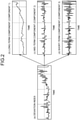
- FIGS. 2(a) to 2(d) illustrate an example where three components (a long-term component, a mid-term component, and a short-term component) are separated from the deviation index using an exponential smoothing method.
- the long-term component (low frequency component) illustrated in FIG. 2(b) indicates a trend of the most smoothed deviation index.
- the short-term component (high frequency component) illustrated in FIG. 2(d) has the most variation components.
- the mid-term component (intermediate frequency component) illustrated in FIG. 2(c) is regarded to be between the long-term component and the short-term component.
- the original deviation index illustrated in FIG. 2(a) is obtained by summing the three components illustrated in FIGS. 2(b) to 2(d) .
- the characteristic value computation unit 13 computes, for each bath process of the process, a characteristic value from each component computed by the component separation computation unit 12. Specifically, the characteristic value computation unit 13 computes at least one of statistics from each component separated by the component separation computation unit 12 for each bath process of the process.
- the statistics include: an average value, a maximum value, a difference value (max - min) between the maximum value and a minimum value, a standard deviation, a difference value between a front half portion and a rear half portion for clarifying a trend of a waveform, the number of crossings with the average value (average number of crossings) and a density of an average crossing obtained by dividing the average number of crossings by the number of pieces of data in the batch process for catching frequency components of the wave form, and a computation value based on the difference value between the maximum value and the minimum value for catching a pulse waveform.
- the values computed as the characteristic values are not limited to those described above. The values may be applicable that are obtained by extracting periodic features, for example.
- the difference value between the front half portion and the rear half portion means a difference between the average values of the half portions of data of the batch process separated by half and half based on time or the number of pieces of data, for example.
- the separation manner is not limited to that described above.
- the data distribution for the front and rear half portions may be changed taking into consideration of a generated phenomenon, for example. Such feature amounts can catch a rising trend of abnormal control input due to abnormality of an instrument and sharp output drop due to an instrument failure.
- the computation value based on the difference value between the maximum value and the minimum value for catching a pulse waveform means, in data of the batch process, the number of pieces of data that exceeds "(difference value between the maximum value and the minimum value)/2 + the minimum value" or the density obtained by dividing the number of pieces of data by the number of all pieces of data, for example.
- the characteristic value computation unit 13 computes the following statistics. For the long-term component illustrated in FIG. 2(b) , the average value, the difference value between the maximum value and the minimum value, and the difference value between the front and rear half portions are computed.
- the difference value between the maximum value and the minimum value, the standard deviation, the average number of crossings, and the computation value based on the difference value between the maximum value and the minimum value are computed.
- the state determination unit 14 classifies the state of the process using the characteristic values computed by the characteristic value computation unit 13. Specifically, the state determination unit 14 determines which trouble is included in the batch process of the target process using a classification model that represents relations between preliminarily prepared characteristic values and trouble contents.
- the classification model can be structured using machine learning because which trouble occurs in which equipment is determined by a variable name, a component, and the characteristic value of target data. That is, the characteristic values for each variable and for each component are given as input to the machine learning, and then labels of the trouble contents are given, thereby making it possible to structure the classification model.
- As the machine learning methods a decision tree, a support vector machine, a neural network, and the like, can be used.
- Table 1 illustrates an example of the classification model.
- a slow change between the batch processes can be caught by the average value computed from the long-term component (a component 1) illustrated in FIG. 2(b) .
- a major trouble example is aging deterioration of the machine accuracy of the equipment.
- a steep change in the batch process can be caught by the difference value between the maximum value and the minimum value computed for the component 1.
- a major trouble example is a sudden failure of a part structuring the equipment.
- a periodic fluctuation in the batch process can be caught by the standard deviation, and the difference value between the maximum value and the minimum value computed for the mid-term component (a component 2) illustrated in FIG. 2(c) .
- a major trouble example is control system hunting (e.g., hunting of a tension component).
- An increase in noise can be caught by the standard deviation computed for the short-term component (a component 3) illustrated in FIG. 2(d) .
- a major trouble example is a sensor noise and a disturbance fluctuation.
- the pulse-like noise can be caught by the difference value between the maximum value and the minimum value computed for the component 3.
- a major trouble example is a sensor cable failure and the like.
- Table 1 Component Characteristic value Change in characteristic value Trouble example Component 1 Average value Slow change between batches Aging deterioration of machine accuracy of equipment max - min Steep change in batch Sudden failure of part structuring equipment Component 2 Standard deviation Periodic fluctuation Control system hunting max - min Component 3 Standard deviation Increase in noise Sensor noise, Disturbance fluctuation max - min Pulse-like noise Sensor cable failure
- the similar case search unit 15 searches the operation DB 4 for data of operation cases similar to the target process by using the characteristic values computed by the characteristic value computation unit 13. Specifically, the similar case search unit 15 defines a distance in a variable space composed of the characteristic values computed for each variable and for each component, and computes, as a similarity, a resemblance between the target process and the past operation case stored in the operation DB 4 on the basis of the distance. The similar case search unit 15 outputs the past operation cases to the output unit 3 in decreasing order of similarities. As an example of the distance definition, a Euclidean distance can be exemplified.
- a cosine similarity based on an angle between characteristic value vectors can be exemplified in addition to the similarity based on the Euclidean distance between the characteristic value vectors composed of the characteristic values of the operation cases.
- the cosine similarity calculates a cosine value of an angle made between two vectors on the basis of a mathematical formula of an inner product of two vectors (a ⁇ b in Table 2). The use of the search method using which similarity can be selected depending on the situation of the trouble.
- the similarity based on the Euclidean distance is used when the number of characteristic values to be compared is small (a case where the cause of the trouble is clear) while the cosine similarity is used when the number of characteristic values to be compared is large (a case where the cause of the trouble is not clear).
- the cosine similarity is used for finding a tendency of an output, not a size, of each characteristic value because the cosine similarity is based on calculation of an angle.
- the cosine similarity is, thus, suitable for finding a tendency at a high dimension.
- the guidance display unit 16 displays, as guidance, the details of the trouble case from data of the past troubles when the similarity computed by the similar case search unit 15 exceeds a set threshold.
- the guidance display content in addition to designated observation data or a setting value that indicates the operation state of the trouble case, an action (e.g., an item and operation amount of an operation end operated by the operation of the target process) taken for trouble prevention can be exemplified.
- the guidance display includes not only the registered contents but also the characteristic value contributing to the similarity as a contribution.
- the contribution that indicates the characteristic value contributing to the resemblance to the trouble case is calculated on the basis of the similarity computation method of the trouble as illustrated in Table 2.
- d represents the Euclidean distance between two points for similarity search
- d i represents the distance of i-th characteristic value
- a and b represent the vectors of the two search points
- a i and b i represent i-th elements of the respective vectors.
- the process state monitoring device 1 in the embodiment of the present invention includes: the component separation computation unit 12 that separates two or more components from the deviation index; the characteristic value computation unit 13 that computes, for each bath process of the process, the characteristic value from each component separated by the component separation computation unit 12; and the state determination unit 14 that classifies the state of the process on the basis of the characteristic values computed by the characteristic value computation unit 13, thereby making it possible to identify the state of the process in detail.
- the present invention is, however, not limited by the description and the drawings, which are part of the disclosure of the present invention, of the embodiment.
- two or more components are separated from the time series data of the value indicating the state of the process (e.g., data of a single point of a rolled material).
- the time series data may be converted into data in a length direction (e.g., data in the length direction of the rolled material) and two or more components may be separated from the data in the length direction.
- the aspect that uses data for each batch process of the process is described.
- the technology of the present invention can be applied when the process is a target that is operated continuously and successively, and in which a certain time period is preliminarily defined that can evaluate regular operation taking into consideration of dynamic characteristics of the process, and result data is managed for each certain time period, as described above.
- the process is, thus, included in the scope of the present invention.
- the certain time period is not always required to be the identical time period.
- the certain time period can be determined in various ways such as on a minute basis, on an hour basis, on a day basis, or a batch basis as long as the deviation index can be evaluated. They are also included in the scope of the present invention.
- Other embodiments, examples, operation techniques, and the like that are practiced by those skilled in the art are all included in the scope of the present invention.
- a process state monitoring device and a process state monitoring method that can identify the state of the process in detail can be provided.
Landscapes
- Engineering & Computer Science (AREA)
- Physics & Mathematics (AREA)
- General Physics & Mathematics (AREA)
- Automation & Control Theory (AREA)
- Theoretical Computer Science (AREA)
- General Engineering & Computer Science (AREA)
- Data Mining & Analysis (AREA)
- Mathematical Physics (AREA)
- Computational Mathematics (AREA)
- Mathematical Analysis (AREA)
- Mathematical Optimization (AREA)
- Pure & Applied Mathematics (AREA)
- Quality & Reliability (AREA)
- Manufacturing & Machinery (AREA)
- Human Computer Interaction (AREA)
- Probability & Statistics with Applications (AREA)
- Databases & Information Systems (AREA)
- Software Systems (AREA)
- Bioinformatics & Computational Biology (AREA)
- Bioinformatics & Cheminformatics (AREA)
- Algebra (AREA)
- Evolutionary Biology (AREA)
- Operations Research (AREA)
- Life Sciences & Earth Sciences (AREA)
- Artificial Intelligence (AREA)
- Evolutionary Computation (AREA)
- Testing And Monitoring For Control Systems (AREA)
Abstract
Description
- The present invention relates to a process state monitoring device and a process state monitoring method that monitor a state of a process such as a manufacturing process.
- For methods of diagnosing states, particularly abnormal states, of processes such as manufacturing processes, power generation processes, conveyance processes, and waste liquid treatment processes, a model base approach and a database approach are available. The model base approach constructs a model that expresses a physical or a chemical phenomenon in a process with a mathematical expression, and diagnoses the state of the process using the constructed model. On the other hand, the database approach constructs a statistical analytic model from operation data obtained in a process and diagnoses the state of the process using the constructed model.
- In the manufacturing process such as a steel process, a vast number of operation patterns are present because various types and sizes of products are manufactured in a single manufacturing line. The manufacturing process such as a blast furnace process varies largely because natural objects such as iron ore and coke are used as raw materials. When the manufacturing state of the manufacturing process such as the steel process is diagnosed, the approach based on only the model base approach, thus, has a limitation.
- The database approach includes: a diagnosis method that makes operation data at the past occurrences of abnormalities into a database and determines a resemblance to current operation data; and a diagnosis method that makes, conversely, operation data at normal operation into a database and determines a difference from current operation data. However, in the manufacturing process such as the steel process, which uses a large number of pieces of equipment for manufacturing, an unprecedented trouble often occurs in a case where a lot of equipment is aged, particularly like Japan. The former diagnosis method based on the past trouble cases, thus, has a limit to the diagnosis of abnormal states.
- On the other hand, the latter diagnosis methods include those described in
Patent Literatures Patent Literatures Patent Literature 3.Patent Literature 3 describes a method that obtains variation indexes from prediction errors of a plurality of sub-models once and determines the state of a process on the basis of the patterns of the deviation indexes. With the method, inherently unusual situations can be organized efficiently because diversity is limited in the states represented by the sub-models. Citation List -
- Patent Literature 1:
Japanese Patent No. 5651998 - Patent Literature 2:
Japanese Patent No. 5499900 - Patent Literature 3:
Japanese Patent Application Laid-open No. 2018-014093 - However, since the occurrence forms of the deviation indexes differ according to the contents of troubles, the method described above cannot monitor the state of process thoroughly. For example, for a target that a process is performed by repeated batch processes, the deviation indexes corresponding to the state of the machine slowly increase between the batch processes of the process in the case of deterioration of equipment machine accuracy with an elapse of time. In contrast, when a sudden failure occurs, the corresponding deviation index steeply increases in the batch process of the process. A sudden failure occurring between the batch processes can be found as abnormal before start of the next batch process. Measures, thus, can be taken in advance. The failure does not become a big problem. When a trouble occurs in a control system, the trouble often causes hunting. In this case, the deviation index fluctuates with a characteristic frequency in the batch process. When a sensor failure or a disturbance fluctuation occurs, noises are increased. When a cable failure occurs, pulse-like noises are superimposed. Even when a process is a target that is operated continuously and successively, a certain time period is preliminarily defined that can evaluate regular operation taking into consideration of dynamic characteristics of the process, and result data is managed for each certain time period, the same situation as that described above occurs. When a model taken into consideration of dynamic characteristics of a process is defined and result data is managed for each preliminarily defined certain time period, such as on a minute basis, on an hour basis, or on a day basis, using the deviation indexes computed by the model, the same situation as that described above occurs. Therefore, it has been expected that a technique is provided that can identify a trouble further in detail by taking into consideration of an occurrence form of the deviation index.
- The invention is made in view of above problems, and an object of the present invention is to provide a process state monitoring device and a process state monitoring method that can identify a state of a process in detail.
- To solve the problem and achieve the object, a process state monitoring device according to the present invention includes: a component separation computation unit configured to separate two or more components from time series data of a value indicating a state of a process; a characteristic value computation unit configured to compute a characteristic value from each component separated by the component separation computation unit; and a state determination unit configured to classify the state of the process on the basis of the characteristic values computed by the characteristic value computation unit.
- Moreover, the process state monitoring device according to the present invention further includes a similar case search unit configured to search a past database for an operation case similar to the process on the basis of the characteristic values computed by the characteristic value computation unit.
- Moreover, in the process state monitoring device according to the present invention, the time series data is time series data of a difference value between a prediction value and a result value of the value.
- Moreover, in the process state monitoring device according to the present invention, the time series data is time series data of a difference value between the value and a preset value obtained at a time at which the state of the process is normal, or time series data of a value of a ratio of the value to the preset value obtained at the time at which the state of the process is normal.
- Moreover, in the process state monitoring device according to the present invention, the component separation computation unit is configured to separate the components from the time series data by filtering processing.
- Moreover, in the process state monitoring device according to the present invention, the characteristic value computation unit is configured to compute, as the characteristic value, at least one of statistics including an average value, a maximum value, a difference value between the maximum value and a minimum value, a standard deviation, a difference value between a front half portion and a rear half portion, an average number of crossings, and a computation value based on the difference value between the maximum value and the minimum value.
- Moreover, in the process state monitoring device according to the present invention, the state determination unit is configured to classify the state of the process using a machine learning technique.
- Moreover, in the process state monitoring device according to the present invention, the similar case search unit is configured to determine a similarity of each operation case on the basis of a distance and/or an angle in a variable space composed of a plurality of characteristic values, and compute, as a contribution, the component contributing to the similarity.
- Moreover, the process state monitoring device according to the present invention further includes a guidance display unit configured to display the similarity and the contribution of each operation case, the similarity and the contribution being computed by the similar case search unit, and an action taken in, and an operation state of, the searched operation case.
- Moreover, a process state monitoring method according to the present invention includes: a component separation computation step of separating two or more components from time series data of a value indicating a state of a process; a characteristic value computation step of computing a characteristic value from each component separated at the component separation computation step; and a state determination step of classifying the state of the process on the basis of the characteristic values computed at the characteristic value computation step.
- The process state monitoring device and the process state monitoring method according to the present invention can identify the state of the process in detail. Brief Description of Drawings
-
FIG. 1 is a block diagram illustrating a structure of a process state monitoring device in an embodiment of the present invention. -
FIG. 2 is a diagram illustrating an example where three components are separated from a deviation index. Description of Embodiment - The following describes a structure of a process state monitoring device in an embodiment of the present invention with reference to the attached drawings.
-
FIG. 1 is a block diagram illustrating the structure of the process state monitoring device in the embodiment of the present invention. As illustrated inFIG. 1 , a processstate monitoring device 1 in the embodiment of the present invention is a device to diagnose states of processes such as manufacturing processes, power generation processes, conveyance processes, and waste liquid treatment processes, and is structured by an information processing device such as a computer. In the embodiment, aninput unit 2, anoutput unit 3, and an operation database (operation DB) 4 are connected to the processstate monitoring device 1. - As a result of a computation processing device in the information processing device executing a computer program, the process
state monitoring device 1 functions as a deviationindex calculation unit 11, a component separation computation unit 12, a characteristicvalue computation unit 13, astate determination unit 14, a similarcase search unit 15, and aguidance display unit 16. - The deviation
index calculation unit 11 calculates a deviation index that indicates by what degree the state of the process is deviated from the state when the process state is normal using time series data of a value indicating the state of the process, the time series data being input from theinput unit 2. Specifically, when the value indicating the state of the process is a detection value of any of a vibration sensor, an acoustic sensor, and a temperature sensor that are installed in or near equipment, the detection value is a value indicating the state of the equipment. Thus, a computation to compare a value at the normal process state with the detection value is enough. For example, the deviationindex calculation unit 11 sets a normal time period preliminarily and computes an average value and a standard deviation of the detection values in the time period. This makes it possible for the deviation index to be calculated as (the detection value - the average value in the normal time period)/the standard deviation in the normal time period. When the value indicating the state of the process is not the value indicating the state of the equipment directly as described above, a model is structured that predicts the value and a difference between the prediction value by the model and an actual value can be set as the deviation index. As the model described above, a theoretical model, a multiple regression model, and a statistical model can be exemplified. When the equipment is rolling equipment, as a value indicating the state of the equipment, a differential load, a sum load, a roll position, and a tension between pieces of rolling equipment can be exemplified. - The component separation computation unit 12 separates at least two or more components from the deviation index computed by the deviation
index calculation unit 11 for each predetermined certain time period, such as for each bath process of the process. The following describes an example where data is processed for each batch process. The same processing can be also done for the data processing performed for each predetermined certain time period. Specifically, the component separation computation unit 12 separates two or more frequency components having different time constants from the deviation index using filtering processing such as an exponential smoothing method, or multiplex resolution analysis, which is one of wavelet analysis.FIGS. 2(a) to 2(d) illustrate an example where three components (a long-term component, a mid-term component, and a short-term component) are separated from the deviation index using an exponential smoothing method. The long-term component (low frequency component) illustrated inFIG. 2(b) indicates a trend of the most smoothed deviation index. The short-term component (high frequency component) illustrated inFIG. 2(d) has the most variation components. The mid-term component (intermediate frequency component) illustrated inFIG. 2(c) is regarded to be between the long-term component and the short-term component. The original deviation index illustrated inFIG. 2(a) is obtained by summing the three components illustrated inFIGS. 2(b) to 2(d) . - The characteristic
value computation unit 13 computes, for each bath process of the process, a characteristic value from each component computed by the component separation computation unit 12. Specifically, the characteristicvalue computation unit 13 computes at least one of statistics from each component separated by the component separation computation unit 12 for each bath process of the process. The statistics include: an average value, a maximum value, a difference value (max - min) between the maximum value and a minimum value, a standard deviation, a difference value between a front half portion and a rear half portion for clarifying a trend of a waveform, the number of crossings with the average value (average number of crossings) and a density of an average crossing obtained by dividing the average number of crossings by the number of pieces of data in the batch process for catching frequency components of the wave form, and a computation value based on the difference value between the maximum value and the minimum value for catching a pulse waveform. The values computed as the characteristic values are not limited to those described above. The values may be applicable that are obtained by extracting periodic features, for example. Here, the difference value between the front half portion and the rear half portion means a difference between the average values of the half portions of data of the batch process separated by half and half based on time or the number of pieces of data, for example. However, the separation manner is not limited to that described above. The data distribution for the front and rear half portions may be changed taking into consideration of a generated phenomenon, for example. Such feature amounts can catch a rising trend of abnormal control input due to abnormality of an instrument and sharp output drop due to an instrument failure. The computation value based on the difference value between the maximum value and the minimum value for catching a pulse waveform means, in data of the batch process, the number of pieces of data that exceeds "(difference value between the maximum value and the minimum value)/2 + the minimum value" or the density obtained by dividing the number of pieces of data by the number of all pieces of data, for example. These values have advantages that features can be extracted even when the frequency cannot be measured accurately due to the small number of pieces of data, and calculated and structured easily. Here, for example, the characteristicvalue computation unit 13 computes the following statistics. For the long-term component illustrated inFIG. 2(b) , the average value, the difference value between the maximum value and the minimum value, and the difference value between the front and rear half portions are computed. For the mid-term component illustrated inFIG. 2(c) and the short-term component illustrated inFIG. 2(d) , the difference value between the maximum value and the minimum value, the standard deviation, the average number of crossings, and the computation value based on the difference value between the maximum value and the minimum value are computed. - The
state determination unit 14 classifies the state of the process using the characteristic values computed by the characteristicvalue computation unit 13. Specifically, thestate determination unit 14 determines which trouble is included in the batch process of the target process using a classification model that represents relations between preliminarily prepared characteristic values and trouble contents. The classification model can be structured using machine learning because which trouble occurs in which equipment is determined by a variable name, a component, and the characteristic value of target data. That is, the characteristic values for each variable and for each component are given as input to the machine learning, and then labels of the trouble contents are given, thereby making it possible to structure the classification model. As the machine learning methods, a decision tree, a support vector machine, a neural network, and the like, can be used. - Table 1 illustrates an example of the classification model. As illustrated in Table 1, a slow change between the batch processes can be caught by the average value computed from the long-term component (a component 1) illustrated in
FIG. 2(b) . In this case, a major trouble example is aging deterioration of the machine accuracy of the equipment. A steep change in the batch process can be caught by the difference value between the maximum value and the minimum value computed for thecomponent 1. In this case, a major trouble example is a sudden failure of a part structuring the equipment. On the other hand, a periodic fluctuation in the batch process can be caught by the standard deviation, and the difference value between the maximum value and the minimum value computed for the mid-term component (a component 2) illustrated inFIG. 2(c) . In this case, a major trouble example is control system hunting (e.g., hunting of a tension component). An increase in noise can be caught by the standard deviation computed for the short-term component (a component 3) illustrated inFIG. 2(d) . In this case, a major trouble example is a sensor noise and a disturbance fluctuation. The pulse-like noise can be caught by the difference value between the maximum value and the minimum value computed for thecomponent 3. In this case, a major trouble example is a sensor cable failure and the like.Table 1 Component Characteristic value Change in characteristic value Trouble example Component 1 Average value Slow change between batches Aging deterioration of machine accuracy of equipment max - min Steep change in batch Sudden failure of part structuring equipment Component 2 Standard deviation Periodic fluctuation Control system hunting max - min Component 3 Standard deviation Increase in noise Sensor noise, Disturbance fluctuation max - min Pulse-like noise Sensor cable failure - The similar
case search unit 15 searches the operation DB 4 for data of operation cases similar to the target process by using the characteristic values computed by the characteristicvalue computation unit 13. Specifically, the similarcase search unit 15 defines a distance in a variable space composed of the characteristic values computed for each variable and for each component, and computes, as a similarity, a resemblance between the target process and the past operation case stored in the operation DB 4 on the basis of the distance. The similarcase search unit 15 outputs the past operation cases to theoutput unit 3 in decreasing order of similarities. As an example of the distance definition, a Euclidean distance can be exemplified. As the computation method of the similarity, as illustrated in Table 2, a cosine similarity based on an angle between characteristic value vectors can be exemplified in addition to the similarity based on the Euclidean distance between the characteristic value vectors composed of the characteristic values of the operation cases. The cosine similarity calculates a cosine value of an angle made between two vectors on the basis of a mathematical formula of an inner product of two vectors (a·b in Table 2). The use of the search method using which similarity can be selected depending on the situation of the trouble. For an example of the selection, it can be considered that the similarity based on the Euclidean distance is used when the number of characteristic values to be compared is small (a case where the cause of the trouble is clear) while the cosine similarity is used when the number of characteristic values to be compared is large (a case where the cause of the trouble is not clear). Alternatively, the cosine similarity is used for finding a tendency of an output, not a size, of each characteristic value because the cosine similarity is based on calculation of an angle. The cosine similarity is, thus, suitable for finding a tendency at a high dimension. For example, when the cosine similarity is used for rolling process, a tendency of the characteristic values of all signals relating to a single rolling mill is observed to grasp an abnormal tendency of the whole machine, thereby making it possible to search for past similar cases. On the other hand, the similarity based on the Euclidean distance is suitable for searching for the past cases using the characteristic value vectors structured at a low dimension because the similarity based on the Euclidean distance places importance on the size of each characteristic value.Table 2 Similarity calculation formula Contribution calculation formula Similarity based on Euclidean distance 
e-d i Cosine similarity 

- The
guidance display unit 16 displays, as guidance, the details of the trouble case from data of the past troubles when the similarity computed by the similarcase search unit 15 exceeds a set threshold. As the guidance display content, in addition to designated observation data or a setting value that indicates the operation state of the trouble case, an action (e.g., an item and operation amount of an operation end operated by the operation of the target process) taken for trouble prevention can be exemplified. The guidance display includes not only the registered contents but also the characteristic value contributing to the similarity as a contribution. Here, the contribution that indicates the characteristic value contributing to the resemblance to the trouble case is calculated on the basis of the similarity computation method of the trouble as illustrated in Table 2. In Table 2, d represents the Euclidean distance between two points for similarity search, di represents the distance of i-th characteristic value, a and b represent the vectors of the two search points, and ai and bi represent i-th elements of the respective vectors. The guidance display of these contributions allows factors contributing to the similar characteristics to be indicated quantitatively, thereby making it easy to estimate the cause of the trouble. As described above, theguidance display unit 16 displays the similarity, contribution, actual action taken in the past trouble, and the operation state at the trouble time to perform guidance. - As apparent from the above description, the process
state monitoring device 1 in the embodiment of the present invention includes: the component separation computation unit 12 that separates two or more components from the deviation index; the characteristicvalue computation unit 13 that computes, for each bath process of the process, the characteristic value from each component separated by the component separation computation unit 12; and thestate determination unit 14 that classifies the state of the process on the basis of the characteristic values computed by the characteristicvalue computation unit 13, thereby making it possible to identify the state of the process in detail. - The embodiment to which the present invention made by the inventors is applied has been described above. The present invention is, however, not limited by the description and the drawings, which are part of the disclosure of the present invention, of the embodiment. In the embodiment, for example, two or more components are separated from the time series data of the value indicating the state of the process (e.g., data of a single point of a rolled material). However, the time series data may be converted into data in a length direction (e.g., data in the length direction of the rolled material) and two or more components may be separated from the data in the length direction. In the embodiment, the aspect that uses data for each batch process of the process is described. However, the technology of the present invention can be applied when the process is a target that is operated continuously and successively, and in which a certain time period is preliminarily defined that can evaluate regular operation taking into consideration of dynamic characteristics of the process, and result data is managed for each certain time period, as described above. The process is, thus, included in the scope of the present invention. The certain time period is not always required to be the identical time period. The certain time period can be determined in various ways such as on a minute basis, on an hour basis, on a day basis, or a batch basis as long as the deviation index can be evaluated. They are also included in the scope of the present invention. Other embodiments, examples, operation techniques, and the like that are practiced by those skilled in the art are all included in the scope of the present invention.
- According to the present invention, a process state monitoring device and a process state monitoring method that can identify the state of the process in detail can be provided.
-
- 1
- Process state monitoring device
- 2
- Input unit
- 3
- Output unit
- 4
- Operation database (operation DB)
- 11
- Deviation index calculation unit
- 12
- Component separation computation unit
- 13
- Characteristic value computation unit
- 14
- State determination unit
- 15
- Similar case search unit
- 16
- Guidance display unit
Claims (10)
- A process state monitoring device, comprising:a component separation computation unit configured to separate two or more components from time series data of a value indicating a state of a process;a characteristic value computation unit configured to compute a characteristic value from each component separated by the component separation computation unit; anda state determination unit configured to classify the state of the process on the basis of the characteristic values computed by the characteristic value computation unit.
- The process state monitoring device according to claim 1, further comprising a similar case search unit configured to search a past database for an operation case similar to the process on the basis of the characteristic values computed by the characteristic value computation unit.
- The process state monitoring device according to claim 1 or 2, wherein the time series data is time series data of a difference value between a prediction value and a result value of the value.
- The process state monitoring device according to claim 1 or 2, wherein the time series data istime series data of a difference value between the value and a preset value obtained at a time at which the state of the process is normal, ortime series data of a value of a ratio of the value to the preset value obtained at the time at which the state of the process is normal.
- The process state monitoring device according to any one of claims 1 to 4, wherein the component separation computation unit is configured to separate the components from the time series data by filtering processing.
- The process state monitoring device according to any one of claims 1 to 5, wherein the characteristic value computation unit is configured to compute, as the characteristic value, at least one of statistics including an average value, a maximum value, a difference value between the maximum value and a minimum value, a standard deviation, a difference value between a front half portion and a rear half portion, an average number of crossings, and a computation value based on the difference value between the maximum value and the minimum value.
- The process state monitoring device according to any one of claims 1 to 6, wherein the state determination unit is configured to classify the state of the process using a machine learning technique.
- The process state monitoring device according to claim 2, wherein the similar case search unit is configured todetermine a similarity of each operation case on the basis of a distance and/or an angle in a variable space composed of a plurality of characteristic values, andcompute, as a contribution, the component contributing to the similarity.
- The process state monitoring device according to claim 8, further comprising a guidance display unit configured to displaythe similarity and the contribution of each operation case, the similarity and the contribution being computed by the similar case search unit, andan action taken in, and an operation state of, the searched operation case.
- A process state monitoring method, comprising:a component separation computation step of separating two or more components from time series data of a value indicating a state of a process;a characteristic value computation step of computing a characteristic value from each component separated at the component separation computation step; anda state determination step of classifying the state of the process on the basis of the characteristic values computed at the characteristic value computation step.
Applications Claiming Priority (2)
| Application Number | Priority Date | Filing Date | Title |
|---|---|---|---|
| JP2019057695 | 2019-03-26 | ||
| PCT/JP2020/012821 WO2020196441A1 (en) | 2019-03-26 | 2020-03-24 | Process state monitoring device and process state monitoring method |
Publications (3)
| Publication Number | Publication Date |
|---|---|
| EP3951530A1 true EP3951530A1 (en) | 2022-02-09 |
| EP3951530A4 EP3951530A4 (en) | 2022-05-18 |
| EP3951530B1 EP3951530B1 (en) | 2023-12-20 |
Family
ID=72608828
Family Applications (1)
| Application Number | Title | Priority Date | Filing Date |
|---|---|---|---|
| EP20777340.9A Active EP3951530B1 (en) | 2019-03-26 | 2020-03-24 | Process state monitoring device and process state monitoring method |
Country Status (6)
| Country | Link |
|---|---|
| US (1) | US12007758B2 (en) |
| EP (1) | EP3951530B1 (en) |
| JP (1) | JP7180676B2 (en) |
| KR (2) | KR102875526B1 (en) |
| CN (1) | CN113678074B (en) |
| WO (1) | WO2020196441A1 (en) |
Families Citing this family (2)
| Publication number | Priority date | Publication date | Assignee | Title |
|---|---|---|---|---|
| JPWO2024047694A1 (en) * | 2022-08-29 | 2024-03-07 | ||
| CN119989479B (en) * | 2025-01-17 | 2025-08-29 | 江苏绿和环境科技有限公司 | Visual monitoring method, system, equipment and medium for intelligent management of construction waste |
Family Cites Families (26)
| Publication number | Priority date | Publication date | Assignee | Title |
|---|---|---|---|---|
| JPS5445065A (en) | 1977-09-12 | 1979-04-10 | Kito Corp | Chain block frame in light alloy casting in which core plate in steel is buried |
| JP3234064B2 (en) * | 1993-09-02 | 2001-12-04 | キヤノン株式会社 | Image retrieval method and apparatus |
| US6311130B1 (en) * | 1996-08-12 | 2001-10-30 | The United States Of America As Represented By The Administrator Of The National Aeronautics And Space Administration | Computer implemented empirical mode decomposition method, apparatus, and article of manufacture for two-dimensional signals |
| US6616759B2 (en) * | 2001-09-06 | 2003-09-09 | Hitachi, Ltd. | Method of monitoring and/or controlling a semiconductor manufacturing apparatus and a system therefor |
| CN102402650A (en) * | 2001-11-09 | 2012-04-04 | 生命技术公司 | Identification, monitoring and treatment of disease and characterization of biological condition using gene expression profiles |
| EP1579608A4 (en) | 2002-10-11 | 2012-09-05 | Flint Hills Scient Llc | Method, computer program, and system for intrinsic timescale decomposition, filtering, and automated analysis of signals of arbitrary origin or timescale |
| JP4594869B2 (en) * | 2006-01-24 | 2010-12-08 | 富士通株式会社 | Condition monitoring device |
| WO2009125627A1 (en) * | 2008-04-11 | 2009-10-15 | 三菱電機株式会社 | Equipment state detecting apparatus, equipment state detecting method, family member accident detecting apparatus, family member accident detecting system, and family member accident detecting method |
| JP5293115B2 (en) * | 2008-11-26 | 2013-09-18 | 富士通株式会社 | Failure cause estimation method, failure cause estimation device, and program |
| JP5651998B2 (en) | 2010-05-25 | 2015-01-14 | Jfeスチール株式会社 | Abnormality diagnosis method and abnormality diagnosis system using pattern library |
| JP5499900B2 (en) | 2010-05-25 | 2014-05-21 | Jfeスチール株式会社 | Pattern automatic extraction method and pattern automatic extraction system |
| JP2012155361A (en) * | 2011-01-21 | 2012-08-16 | Toshiba Corp | Process monitoring device |
| US8994359B2 (en) * | 2011-08-29 | 2015-03-31 | General Electric Company | Fault detection based on current signature analysis for a generator |
| JP5772546B2 (en) * | 2011-11-28 | 2015-09-02 | 新日鐵住金株式会社 | Operation quality prediction device, operation quality prediction method, computer program, and computer-readable storage medium |
| JP5996384B2 (en) | 2012-11-09 | 2016-09-21 | 株式会社東芝 | Process monitoring diagnostic device, process monitoring diagnostic program |
| US9104942B2 (en) * | 2012-12-19 | 2015-08-11 | Hong Kong Applied Science and Technology Research Institute Company Limited | Perceptual bias level estimation for hand-drawn sketches in sketch-photo matching |
| JP6214889B2 (en) * | 2013-03-14 | 2017-10-18 | 株式会社東芝 | Process monitoring and diagnosis device |
| US20150276557A1 (en) | 2014-03-28 | 2015-10-01 | Hitachi High-Technologies Corporation | State monitoring system, state monitoring method and medium |
| ES2549652B1 (en) * | 2014-04-24 | 2016-10-07 | Alstom Transporte, S.A. | Method and system to automatically detect faults in a rotary axis |
| JP6733164B2 (en) | 2015-02-26 | 2020-07-29 | 富士電機株式会社 | Process monitoring device, process monitoring method and program |
| JP6579163B2 (en) * | 2016-07-06 | 2019-09-25 | Jfeスチール株式会社 | Process condition diagnosis method and condition diagnosis apparatus |
| US10375098B2 (en) * | 2017-01-31 | 2019-08-06 | Splunk Inc. | Anomaly detection based on relationships between multiple time series |
| CN106844161B (en) * | 2017-02-20 | 2020-03-17 | 重庆邮电大学 | Abnormity monitoring and predicting method and system in calculation system with state flow |
| KR102355777B1 (en) * | 2017-06-19 | 2022-01-25 | 제이에프이 스틸 가부시키가이샤 | Process anomalous state diagnostic device and process anomalous state diagnosis method |
| JP6885321B2 (en) * | 2017-12-22 | 2021-06-16 | Jfeスチール株式会社 | Process status diagnosis method and status diagnosis device |
| CN109308447A (en) | 2018-07-29 | 2019-02-05 | 国网上海市电力公司 | Method for Automatically Extracting Equipment Operating Parameters and Operating Status in Electric Power Remote Monitoring |
-
2020
- 2020-03-24 KR KR1020247008635A patent/KR102875526B1/en active Active
- 2020-03-24 US US17/440,267 patent/US12007758B2/en active Active
- 2020-03-24 JP JP2020545819A patent/JP7180676B2/en active Active
- 2020-03-24 EP EP20777340.9A patent/EP3951530B1/en active Active
- 2020-03-24 CN CN202080023623.4A patent/CN113678074B/en active Active
- 2020-03-24 KR KR1020217028937A patent/KR20210124438A/en not_active Ceased
- 2020-03-24 WO PCT/JP2020/012821 patent/WO2020196441A1/en not_active Ceased
Also Published As
| Publication number | Publication date |
|---|---|
| EP3951530B1 (en) | 2023-12-20 |
| KR20240042121A (en) | 2024-04-01 |
| CN113678074B (en) | 2025-05-09 |
| KR20210124438A (en) | 2021-10-14 |
| BR112021017758A2 (en) | 2021-11-23 |
| US12007758B2 (en) | 2024-06-11 |
| JP7180676B2 (en) | 2022-11-30 |
| JPWO2020196441A1 (en) | 2021-04-08 |
| WO2020196441A1 (en) | 2020-10-01 |
| US20220187809A1 (en) | 2022-06-16 |
| EP3951530A4 (en) | 2022-05-18 |
| KR102875526B1 (en) | 2025-10-22 |
| CN113678074A (en) | 2021-11-19 |
Similar Documents
| Publication | Publication Date | Title |
|---|---|---|
| Patel et al. | Euclidean distance based feature ranking and subset selection for bearing fault diagnosis | |
| EP3764184B1 (en) | Abnormality determination assistance device | |
| Jia et al. | Quality-related fault detection approach based on dynamic kernel partial least squares | |
| US10996662B2 (en) | Manufacturing equipment diagnosis support system | |
| CN100489870C (en) | Method and multidimensional system for statistical control of a process | |
| EP3926427A1 (en) | Work efficiency evaluating method, work efficiency evaluating device, and program | |
| WO2021241576A1 (en) | Abnormal modulation cause identification device, abnormal modulation cause identification method, and abnormal modulation cause identification program | |
| CN110531228A (en) | Method, system and medium for judging the severity of partial discharge in GIS based on principal component dimensionality reduction and cluster analysis | |
| EP3951530B1 (en) | Process state monitoring device and process state monitoring method | |
| JP2022066762A (en) | Abnormality diagnostic device and abnormality diagnostic method | |
| CN113420061A (en) | Steady state working condition analysis method, optimization debugging method and system of oil refining and chemical production device | |
| JP5091604B2 (en) | Distribution evaluation method, product manufacturing method, distribution evaluation program, and distribution evaluation system | |
| JP6579163B2 (en) | Process condition diagnosis method and condition diagnosis apparatus | |
| WO2022085350A1 (en) | Method for building abnormality diagnosis model, abnormality diagnosis method, device for building abnormality diagnosis model, and abnormality diagnosis device | |
| Bator et al. | Feature extraction and reduction applied to sensorless drive diagnosis | |
| JP6885321B2 (en) | Process status diagnosis method and status diagnosis device | |
| Zhang et al. | An adaptive pre-warning method based on trend monitoring: Application to an oil refining process | |
| CN119246955A (en) | A method and system for online resistance testing of oxygen-free copper rod | |
| Maduskar et al. | UDDT: An Unsupervised Drift Detection Method for Industrial Time Series Data | |
| JP2000315111A (en) | Diagnosis method and device for equipment and product process abnormal state | |
| JP7806507B2 (en) | Equipment diagnosis device and equipment diagnosis method | |
| Singh et al. | Predicting the remaining useful life of ball bearing under dynamic loading using supervised learning | |
| JP5569324B2 (en) | Operating condition management device | |
| CN107944491B (en) | Quality characteristic symbolization mapping control chart construction method | |
| Teng | Fault diagnosis of rolling bearing based on EEMD and MMTS |
Legal Events
| Date | Code | Title | Description |
|---|---|---|---|
| STAA | Information on the status of an ep patent application or granted ep patent |
Free format text: STATUS: THE INTERNATIONAL PUBLICATION HAS BEEN MADE |
|
| PUAI | Public reference made under article 153(3) epc to a published international application that has entered the european phase |
Free format text: ORIGINAL CODE: 0009012 |
|
| STAA | Information on the status of an ep patent application or granted ep patent |
Free format text: STATUS: REQUEST FOR EXAMINATION WAS MADE |
|
| 17P | Request for examination filed |
Effective date: 20210921 |
|
| AK | Designated contracting states |
Kind code of ref document: A1 Designated state(s): AL AT BE BG CH CY CZ DE DK EE ES FI FR GB GR HR HU IE IS IT LI LT LU LV MC MK MT NL NO PL PT RO RS SE SI SK SM TR |
|
| A4 | Supplementary search report drawn up and despatched |
Effective date: 20220419 |
|
| RIC1 | Information provided on ipc code assigned before grant |
Ipc: G06F 17/14 20060101ALI20220411BHEP Ipc: G05B 23/02 20060101AFI20220411BHEP |
|
| DAV | Request for validation of the european patent (deleted) | ||
| DAX | Request for extension of the european patent (deleted) | ||
| GRAP | Despatch of communication of intention to grant a patent |
Free format text: ORIGINAL CODE: EPIDOSNIGR1 |
|
| STAA | Information on the status of an ep patent application or granted ep patent |
Free format text: STATUS: GRANT OF PATENT IS INTENDED |
|
| RIC1 | Information provided on ipc code assigned before grant |
Ipc: G06F 17/18 20060101ALI20230630BHEP Ipc: G05B 23/02 20060101AFI20230630BHEP |
|
| INTG | Intention to grant announced |
Effective date: 20230720 |
|
| GRAS | Grant fee paid |
Free format text: ORIGINAL CODE: EPIDOSNIGR3 |
|
| GRAA | (expected) grant |
Free format text: ORIGINAL CODE: 0009210 |
|
| STAA | Information on the status of an ep patent application or granted ep patent |
Free format text: STATUS: THE PATENT HAS BEEN GRANTED |
|
| AK | Designated contracting states |
Kind code of ref document: B1 Designated state(s): AL AT BE BG CH CY CZ DE DK EE ES FI FR GB GR HR HU IE IS IT LI LT LU LV MC MK MT NL NO PL PT RO RS SE SI SK SM TR |
|
| REG | Reference to a national code |
Ref country code: GB Ref legal event code: FG4D |
|
| REG | Reference to a national code |
Ref country code: DE Ref legal event code: R096 Ref document number: 602020023136 Country of ref document: DE |
|
| REG | Reference to a national code |
Ref country code: CH Ref legal event code: EP |
|
| REG | Reference to a national code |
Ref country code: IE Ref legal event code: FG4D |
|
| PG25 | Lapsed in a contracting state [announced via postgrant information from national office to epo] |
Ref country code: GR Free format text: LAPSE BECAUSE OF FAILURE TO SUBMIT A TRANSLATION OF THE DESCRIPTION OR TO PAY THE FEE WITHIN THE PRESCRIBED TIME-LIMIT Effective date: 20240321 |
|
| REG | Reference to a national code |
Ref country code: LT Ref legal event code: MG9D |
|
| PG25 | Lapsed in a contracting state [announced via postgrant information from national office to epo] |
Ref country code: LT Free format text: LAPSE BECAUSE OF FAILURE TO SUBMIT A TRANSLATION OF THE DESCRIPTION OR TO PAY THE FEE WITHIN THE PRESCRIBED TIME-LIMIT Effective date: 20231220 |
|
| REG | Reference to a national code |
Ref country code: NL Ref legal event code: MP Effective date: 20231220 |
|
| PG25 | Lapsed in a contracting state [announced via postgrant information from national office to epo] |
Ref country code: ES Free format text: LAPSE BECAUSE OF FAILURE TO SUBMIT A TRANSLATION OF THE DESCRIPTION OR TO PAY THE FEE WITHIN THE PRESCRIBED TIME-LIMIT Effective date: 20231220 |
|
| PG25 | Lapsed in a contracting state [announced via postgrant information from national office to epo] |
Ref country code: LT Free format text: LAPSE BECAUSE OF FAILURE TO SUBMIT A TRANSLATION OF THE DESCRIPTION OR TO PAY THE FEE WITHIN THE PRESCRIBED TIME-LIMIT Effective date: 20231220 Ref country code: GR Free format text: LAPSE BECAUSE OF FAILURE TO SUBMIT A TRANSLATION OF THE DESCRIPTION OR TO PAY THE FEE WITHIN THE PRESCRIBED TIME-LIMIT Effective date: 20240321 Ref country code: FI Free format text: LAPSE BECAUSE OF FAILURE TO SUBMIT A TRANSLATION OF THE DESCRIPTION OR TO PAY THE FEE WITHIN THE PRESCRIBED TIME-LIMIT Effective date: 20231220 Ref country code: ES Free format text: LAPSE BECAUSE OF FAILURE TO SUBMIT A TRANSLATION OF THE DESCRIPTION OR TO PAY THE FEE WITHIN THE PRESCRIBED TIME-LIMIT Effective date: 20231220 Ref country code: BG Free format text: LAPSE BECAUSE OF FAILURE TO SUBMIT A TRANSLATION OF THE DESCRIPTION OR TO PAY THE FEE WITHIN THE PRESCRIBED TIME-LIMIT Effective date: 20240320 |
|
| REG | Reference to a national code |
Ref country code: AT Ref legal event code: MK05 Ref document number: 1643000 Country of ref document: AT Kind code of ref document: T Effective date: 20231220 |
|
| PG25 | Lapsed in a contracting state [announced via postgrant information from national office to epo] |
Ref country code: NL Free format text: LAPSE BECAUSE OF FAILURE TO SUBMIT A TRANSLATION OF THE DESCRIPTION OR TO PAY THE FEE WITHIN THE PRESCRIBED TIME-LIMIT Effective date: 20231220 |
|
| PG25 | Lapsed in a contracting state [announced via postgrant information from national office to epo] |
Ref country code: SE Free format text: LAPSE BECAUSE OF FAILURE TO SUBMIT A TRANSLATION OF THE DESCRIPTION OR TO PAY THE FEE WITHIN THE PRESCRIBED TIME-LIMIT Effective date: 20231220 Ref country code: RS Free format text: LAPSE BECAUSE OF FAILURE TO SUBMIT A TRANSLATION OF THE DESCRIPTION OR TO PAY THE FEE WITHIN THE PRESCRIBED TIME-LIMIT Effective date: 20231220 Ref country code: NO Free format text: LAPSE BECAUSE OF FAILURE TO SUBMIT A TRANSLATION OF THE DESCRIPTION OR TO PAY THE FEE WITHIN THE PRESCRIBED TIME-LIMIT Effective date: 20240320 Ref country code: NL Free format text: LAPSE BECAUSE OF FAILURE TO SUBMIT A TRANSLATION OF THE DESCRIPTION OR TO PAY THE FEE WITHIN THE PRESCRIBED TIME-LIMIT Effective date: 20231220 Ref country code: LV Free format text: LAPSE BECAUSE OF FAILURE TO SUBMIT A TRANSLATION OF THE DESCRIPTION OR TO PAY THE FEE WITHIN THE PRESCRIBED TIME-LIMIT Effective date: 20231220 Ref country code: HR Free format text: LAPSE BECAUSE OF FAILURE TO SUBMIT A TRANSLATION OF THE DESCRIPTION OR TO PAY THE FEE WITHIN THE PRESCRIBED TIME-LIMIT Effective date: 20231220 |
|
| PG25 | Lapsed in a contracting state [announced via postgrant information from national office to epo] |
Ref country code: IS Free format text: LAPSE BECAUSE OF FAILURE TO SUBMIT A TRANSLATION OF THE DESCRIPTION OR TO PAY THE FEE WITHIN THE PRESCRIBED TIME-LIMIT Effective date: 20240420 |
|
| PG25 | Lapsed in a contracting state [announced via postgrant information from national office to epo] |
Ref country code: CZ Free format text: LAPSE BECAUSE OF FAILURE TO SUBMIT A TRANSLATION OF THE DESCRIPTION OR TO PAY THE FEE WITHIN THE PRESCRIBED TIME-LIMIT Effective date: 20231220 Ref country code: AT Free format text: LAPSE BECAUSE OF FAILURE TO SUBMIT A TRANSLATION OF THE DESCRIPTION OR TO PAY THE FEE WITHIN THE PRESCRIBED TIME-LIMIT Effective date: 20231220 |
|
| PG25 | Lapsed in a contracting state [announced via postgrant information from national office to epo] |
Ref country code: SK Free format text: LAPSE BECAUSE OF FAILURE TO SUBMIT A TRANSLATION OF THE DESCRIPTION OR TO PAY THE FEE WITHIN THE PRESCRIBED TIME-LIMIT Effective date: 20231220 |
|
| PG25 | Lapsed in a contracting state [announced via postgrant information from national office to epo] |
Ref country code: SM Free format text: LAPSE BECAUSE OF FAILURE TO SUBMIT A TRANSLATION OF THE DESCRIPTION OR TO PAY THE FEE WITHIN THE PRESCRIBED TIME-LIMIT Effective date: 20231220 Ref country code: SK Free format text: LAPSE BECAUSE OF FAILURE TO SUBMIT A TRANSLATION OF THE DESCRIPTION OR TO PAY THE FEE WITHIN THE PRESCRIBED TIME-LIMIT Effective date: 20231220 Ref country code: RO Free format text: LAPSE BECAUSE OF FAILURE TO SUBMIT A TRANSLATION OF THE DESCRIPTION OR TO PAY THE FEE WITHIN THE PRESCRIBED TIME-LIMIT Effective date: 20231220 Ref country code: IT Free format text: LAPSE BECAUSE OF FAILURE TO SUBMIT A TRANSLATION OF THE DESCRIPTION OR TO PAY THE FEE WITHIN THE PRESCRIBED TIME-LIMIT Effective date: 20231220 Ref country code: IS Free format text: LAPSE BECAUSE OF FAILURE TO SUBMIT A TRANSLATION OF THE DESCRIPTION OR TO PAY THE FEE WITHIN THE PRESCRIBED TIME-LIMIT Effective date: 20240420 Ref country code: EE Free format text: LAPSE BECAUSE OF FAILURE TO SUBMIT A TRANSLATION OF THE DESCRIPTION OR TO PAY THE FEE WITHIN THE PRESCRIBED TIME-LIMIT Effective date: 20231220 Ref country code: CZ Free format text: LAPSE BECAUSE OF FAILURE TO SUBMIT A TRANSLATION OF THE DESCRIPTION OR TO PAY THE FEE WITHIN THE PRESCRIBED TIME-LIMIT Effective date: 20231220 Ref country code: AT Free format text: LAPSE BECAUSE OF FAILURE TO SUBMIT A TRANSLATION OF THE DESCRIPTION OR TO PAY THE FEE WITHIN THE PRESCRIBED TIME-LIMIT Effective date: 20231220 |
|
| PG25 | Lapsed in a contracting state [announced via postgrant information from national office to epo] |
Ref country code: PL Free format text: LAPSE BECAUSE OF FAILURE TO SUBMIT A TRANSLATION OF THE DESCRIPTION OR TO PAY THE FEE WITHIN THE PRESCRIBED TIME-LIMIT Effective date: 20231220 Ref country code: PT Free format text: LAPSE BECAUSE OF FAILURE TO SUBMIT A TRANSLATION OF THE DESCRIPTION OR TO PAY THE FEE WITHIN THE PRESCRIBED TIME-LIMIT Effective date: 20240422 |
|
| PG25 | Lapsed in a contracting state [announced via postgrant information from national office to epo] |
Ref country code: PT Free format text: LAPSE BECAUSE OF FAILURE TO SUBMIT A TRANSLATION OF THE DESCRIPTION OR TO PAY THE FEE WITHIN THE PRESCRIBED TIME-LIMIT Effective date: 20240422 Ref country code: PL Free format text: LAPSE BECAUSE OF FAILURE TO SUBMIT A TRANSLATION OF THE DESCRIPTION OR TO PAY THE FEE WITHIN THE PRESCRIBED TIME-LIMIT Effective date: 20231220 |
|
| REG | Reference to a national code |
Ref country code: DE Ref legal event code: R097 Ref document number: 602020023136 Country of ref document: DE |
|
| REG | Reference to a national code |
Ref country code: DE Ref legal event code: R119 Ref document number: 602020023136 Country of ref document: DE |
|
| PG25 | Lapsed in a contracting state [announced via postgrant information from national office to epo] |
Ref country code: DK Free format text: LAPSE BECAUSE OF FAILURE TO SUBMIT A TRANSLATION OF THE DESCRIPTION OR TO PAY THE FEE WITHIN THE PRESCRIBED TIME-LIMIT Effective date: 20231220 |
|
| PLBE | No opposition filed within time limit |
Free format text: ORIGINAL CODE: 0009261 |
|
| STAA | Information on the status of an ep patent application or granted ep patent |
Free format text: STATUS: NO OPPOSITION FILED WITHIN TIME LIMIT |
|
| PG25 | Lapsed in a contracting state [announced via postgrant information from national office to epo] |
Ref country code: SI Free format text: LAPSE BECAUSE OF FAILURE TO SUBMIT A TRANSLATION OF THE DESCRIPTION OR TO PAY THE FEE WITHIN THE PRESCRIBED TIME-LIMIT Effective date: 20231220 |
|
| PG25 | Lapsed in a contracting state [announced via postgrant information from national office to epo] |
Ref country code: SI Free format text: LAPSE BECAUSE OF FAILURE TO SUBMIT A TRANSLATION OF THE DESCRIPTION OR TO PAY THE FEE WITHIN THE PRESCRIBED TIME-LIMIT Effective date: 20231220 Ref country code: DK Free format text: LAPSE BECAUSE OF FAILURE TO SUBMIT A TRANSLATION OF THE DESCRIPTION OR TO PAY THE FEE WITHIN THE PRESCRIBED TIME-LIMIT Effective date: 20231220 |
|
| REG | Reference to a national code |
Ref country code: CH Ref legal event code: PL |
|
| PG25 | Lapsed in a contracting state [announced via postgrant information from national office to epo] |
Ref country code: LU Free format text: LAPSE BECAUSE OF NON-PAYMENT OF DUE FEES Effective date: 20240324 |
|
| PG25 | Lapsed in a contracting state [announced via postgrant information from national office to epo] |
Ref country code: MC Free format text: LAPSE BECAUSE OF FAILURE TO SUBMIT A TRANSLATION OF THE DESCRIPTION OR TO PAY THE FEE WITHIN THE PRESCRIBED TIME-LIMIT Effective date: 20231220 |
|
| 26N | No opposition filed |
Effective date: 20240923 |
|
| GBPC | Gb: european patent ceased through non-payment of renewal fee |
Effective date: 20240324 |
|
| PG25 | Lapsed in a contracting state [announced via postgrant information from national office to epo] |
Ref country code: MC Free format text: LAPSE BECAUSE OF FAILURE TO SUBMIT A TRANSLATION OF THE DESCRIPTION OR TO PAY THE FEE WITHIN THE PRESCRIBED TIME-LIMIT Effective date: 20231220 Ref country code: LU Free format text: LAPSE BECAUSE OF NON-PAYMENT OF DUE FEES Effective date: 20240324 |
|
| REG | Reference to a national code |
Ref country code: BE Ref legal event code: MM Effective date: 20240331 |
|
| PG25 | Lapsed in a contracting state [announced via postgrant information from national office to epo] |
Ref country code: DE Free format text: LAPSE BECAUSE OF NON-PAYMENT OF DUE FEES Effective date: 20241001 |
|
| PG25 | Lapsed in a contracting state [announced via postgrant information from national office to epo] |
Ref country code: BE Free format text: LAPSE BECAUSE OF NON-PAYMENT OF DUE FEES Effective date: 20240331 |
|
| PG25 | Lapsed in a contracting state [announced via postgrant information from national office to epo] |
Ref country code: GB Free format text: LAPSE BECAUSE OF NON-PAYMENT OF DUE FEES Effective date: 20240324 |
|
| PG25 | Lapsed in a contracting state [announced via postgrant information from national office to epo] |
Ref country code: IE Free format text: LAPSE BECAUSE OF NON-PAYMENT OF DUE FEES Effective date: 20240324 |
|
| PG25 | Lapsed in a contracting state [announced via postgrant information from national office to epo] |
Ref country code: IE Free format text: LAPSE BECAUSE OF NON-PAYMENT OF DUE FEES Effective date: 20240324 Ref country code: GB Free format text: LAPSE BECAUSE OF NON-PAYMENT OF DUE FEES Effective date: 20240324 Ref country code: DE Free format text: LAPSE BECAUSE OF NON-PAYMENT OF DUE FEES Effective date: 20241001 Ref country code: BE Free format text: LAPSE BECAUSE OF NON-PAYMENT OF DUE FEES Effective date: 20240331 Ref country code: CH Free format text: LAPSE BECAUSE OF NON-PAYMENT OF DUE FEES Effective date: 20240331 |
|
| PG25 | Lapsed in a contracting state [announced via postgrant information from national office to epo] |
Ref country code: CY Free format text: LAPSE BECAUSE OF FAILURE TO SUBMIT A TRANSLATION OF THE DESCRIPTION OR TO PAY THE FEE WITHIN THE PRESCRIBED TIME-LIMIT; INVALID AB INITIO Effective date: 20200324 |
|
| PG25 | Lapsed in a contracting state [announced via postgrant information from national office to epo] |
Ref country code: HU Free format text: LAPSE BECAUSE OF FAILURE TO SUBMIT A TRANSLATION OF THE DESCRIPTION OR TO PAY THE FEE WITHIN THE PRESCRIBED TIME-LIMIT; INVALID AB INITIO Effective date: 20200324 |
|
| PGFP | Annual fee paid to national office [announced via postgrant information from national office to epo] |
Ref country code: FR Payment date: 20260209 Year of fee payment: 7 |
|
| PGFP | Annual fee paid to national office [announced via postgrant information from national office to epo] |
Ref country code: TR Payment date: 20260323 Year of fee payment: 7 |