EP3951361A1 - Fluorescence observation device - Google Patents
Fluorescence observation device Download PDFInfo
- Publication number
- EP3951361A1 EP3951361A1 EP19921537.7A EP19921537A EP3951361A1 EP 3951361 A1 EP3951361 A1 EP 3951361A1 EP 19921537 A EP19921537 A EP 19921537A EP 3951361 A1 EP3951361 A1 EP 3951361A1
- Authority
- EP
- European Patent Office
- Prior art keywords
- sample piece
- fluorescence
- sample
- tray
- fluorescence observation
- Prior art date
- Legal status (The legal status is an assumption and is not a legal conclusion. Google has not performed a legal analysis and makes no representation as to the accuracy of the status listed.)
- Pending
Links
- 238000001514 detection method Methods 0.000 claims abstract description 34
- 239000003550 marker Substances 0.000 claims abstract description 21
- 238000002073 fluorescence micrograph Methods 0.000 claims abstract description 18
- 238000005520 cutting process Methods 0.000 claims abstract description 15
- 230000005284 excitation Effects 0.000 claims abstract description 14
- 238000009826 distribution Methods 0.000 claims description 9
- 238000005192 partition Methods 0.000 claims description 7
- 238000003705 background correction Methods 0.000 claims description 6
- 239000000523 sample Substances 0.000 description 167
- 206010028980 Neoplasm Diseases 0.000 description 25
- 238000003384 imaging method Methods 0.000 description 7
- 229950003776 protoporphyrin Drugs 0.000 description 7
- PFWFFEYVRFHDBS-JINQPTGOSA-N (2s)-2-amino-5-[(6'-aminospiro[1h-2-benzofuran-3,9'-xanthene]-3'-yl)amino]-5-oxopentanoic acid Chemical compound O1CC2=CC=CC=C2C21C1=CC=C(N)C=C1OC1=CC(NC(=O)CC[C@H](N)C(O)=O)=CC=C21 PFWFFEYVRFHDBS-JINQPTGOSA-N 0.000 description 6
- KSFOVUSSGSKXFI-GAQDCDSVSA-N CC1=C/2NC(\C=C3/N=C(/C=C4\N\C(=C/C5=N/C(=C\2)/C(C=C)=C5C)C(C=C)=C4C)C(C)=C3CCC(O)=O)=C1CCC(O)=O Chemical compound CC1=C/2NC(\C=C3/N=C(/C=C4\N\C(=C/C5=N/C(=C\2)/C(C=C)=C5C)C(C=C)=C4C)C(C)=C3CCC(O)=O)=C1CCC(O)=O KSFOVUSSGSKXFI-GAQDCDSVSA-N 0.000 description 6
- 238000001356 surgical procedure Methods 0.000 description 5
- 238000010586 diagram Methods 0.000 description 4
- 238000010186 staining Methods 0.000 description 4
- 230000002123 temporal effect Effects 0.000 description 4
- 238000007689 inspection Methods 0.000 description 3
- 239000011159 matrix material Substances 0.000 description 3
- 238000003825 pressing Methods 0.000 description 3
- 239000000126 substance Substances 0.000 description 3
- 238000000034 method Methods 0.000 description 2
- 239000011347 resin Substances 0.000 description 2
- 229920005989 resin Polymers 0.000 description 2
- 102000004190 Enzymes Human genes 0.000 description 1
- 108090000790 Enzymes Proteins 0.000 description 1
- 210000004027 cell Anatomy 0.000 description 1
- 210000000170 cell membrane Anatomy 0.000 description 1
- 239000003086 colorant Substances 0.000 description 1
- 230000000694 effects Effects 0.000 description 1
- 238000000799 fluorescence microscopy Methods 0.000 description 1
- 230000002209 hydrophobic effect Effects 0.000 description 1
- 239000007788 liquid Substances 0.000 description 1
- 230000003287 optical effect Effects 0.000 description 1
- 230000001575 pathological effect Effects 0.000 description 1
- 230000000149 penetrating effect Effects 0.000 description 1
- 230000002980 postoperative effect Effects 0.000 description 1
- 238000002360 preparation method Methods 0.000 description 1
- 230000002265 prevention Effects 0.000 description 1
- 230000035945 sensitivity Effects 0.000 description 1
- XLYOFNOQVPJJNP-UHFFFAOYSA-N water Substances O XLYOFNOQVPJJNP-UHFFFAOYSA-N 0.000 description 1
Images



Classifications
-
- G—PHYSICS
- G01—MEASURING; TESTING
- G01N—INVESTIGATING OR ANALYSING MATERIALS BY DETERMINING THEIR CHEMICAL OR PHYSICAL PROPERTIES
- G01N21/00—Investigating or analysing materials by the use of optical means, i.e. using sub-millimetre waves, infrared, visible or ultraviolet light
- G01N21/62—Systems in which the material investigated is excited whereby it emits light or causes a change in wavelength of the incident light
- G01N21/63—Systems in which the material investigated is excited whereby it emits light or causes a change in wavelength of the incident light optically excited
- G01N21/64—Fluorescence; Phosphorescence
- G01N21/6428—Measuring fluorescence of fluorescent products of reactions or of fluorochrome labelled reactive substances, e.g. measuring quenching effects, using measuring "optrodes"
-
- G—PHYSICS
- G01—MEASURING; TESTING
- G01N—INVESTIGATING OR ANALYSING MATERIALS BY DETERMINING THEIR CHEMICAL OR PHYSICAL PROPERTIES
- G01N21/00—Investigating or analysing materials by the use of optical means, i.e. using sub-millimetre waves, infrared, visible or ultraviolet light
- G01N21/62—Systems in which the material investigated is excited whereby it emits light or causes a change in wavelength of the incident light
- G01N21/63—Systems in which the material investigated is excited whereby it emits light or causes a change in wavelength of the incident light optically excited
- G01N21/64—Fluorescence; Phosphorescence
- G01N21/645—Specially adapted constructive features of fluorimeters
- G01N21/6456—Spatial resolved fluorescence measurements; Imaging
-
- G—PHYSICS
- G01—MEASURING; TESTING
- G01N—INVESTIGATING OR ANALYSING MATERIALS BY DETERMINING THEIR CHEMICAL OR PHYSICAL PROPERTIES
- G01N21/00—Investigating or analysing materials by the use of optical means, i.e. using sub-millimetre waves, infrared, visible or ultraviolet light
- G01N21/62—Systems in which the material investigated is excited whereby it emits light or causes a change in wavelength of the incident light
- G01N21/63—Systems in which the material investigated is excited whereby it emits light or causes a change in wavelength of the incident light optically excited
- G01N21/64—Fluorescence; Phosphorescence
- G01N21/645—Specially adapted constructive features of fluorimeters
-
- G—PHYSICS
- G01—MEASURING; TESTING
- G01N—INVESTIGATING OR ANALYSING MATERIALS BY DETERMINING THEIR CHEMICAL OR PHYSICAL PROPERTIES
- G01N21/00—Investigating or analysing materials by the use of optical means, i.e. using sub-millimetre waves, infrared, visible or ultraviolet light
- G01N21/62—Systems in which the material investigated is excited whereby it emits light or causes a change in wavelength of the incident light
- G01N21/63—Systems in which the material investigated is excited whereby it emits light or causes a change in wavelength of the incident light optically excited
- G01N21/64—Fluorescence; Phosphorescence
- G01N21/6486—Measuring fluorescence of biological material, e.g. DNA, RNA, cells
-
- G—PHYSICS
- G01—MEASURING; TESTING
- G01N—INVESTIGATING OR ANALYSING MATERIALS BY DETERMINING THEIR CHEMICAL OR PHYSICAL PROPERTIES
- G01N1/00—Sampling; Preparing specimens for investigation
- G01N1/28—Preparing specimens for investigation including physical details of (bio-)chemical methods covered elsewhere, e.g. G01N33/50, C12Q
- G01N1/286—Preparing specimens for investigation including physical details of (bio-)chemical methods covered elsewhere, e.g. G01N33/50, C12Q involving mechanical work, e.g. chopping, disintegrating, compacting, homogenising
-
- G—PHYSICS
- G01—MEASURING; TESTING
- G01N—INVESTIGATING OR ANALYSING MATERIALS BY DETERMINING THEIR CHEMICAL OR PHYSICAL PROPERTIES
- G01N1/00—Sampling; Preparing specimens for investigation
- G01N1/28—Preparing specimens for investigation including physical details of (bio-)chemical methods covered elsewhere, e.g. G01N33/50, C12Q
- G01N1/286—Preparing specimens for investigation including physical details of (bio-)chemical methods covered elsewhere, e.g. G01N33/50, C12Q involving mechanical work, e.g. chopping, disintegrating, compacting, homogenising
- G01N2001/2873—Cutting or cleaving
-
- G—PHYSICS
- G01—MEASURING; TESTING
- G01N—INVESTIGATING OR ANALYSING MATERIALS BY DETERMINING THEIR CHEMICAL OR PHYSICAL PROPERTIES
- G01N21/00—Investigating or analysing materials by the use of optical means, i.e. using sub-millimetre waves, infrared, visible or ultraviolet light
- G01N21/01—Arrangements or apparatus for facilitating the optical investigation
- G01N21/03—Cuvette constructions
- G01N2021/0339—Holders for solids, powders
-
- G—PHYSICS
- G01—MEASURING; TESTING
- G01N—INVESTIGATING OR ANALYSING MATERIALS BY DETERMINING THEIR CHEMICAL OR PHYSICAL PROPERTIES
- G01N21/00—Investigating or analysing materials by the use of optical means, i.e. using sub-millimetre waves, infrared, visible or ultraviolet light
- G01N21/62—Systems in which the material investigated is excited whereby it emits light or causes a change in wavelength of the incident light
- G01N21/63—Systems in which the material investigated is excited whereby it emits light or causes a change in wavelength of the incident light optically excited
- G01N21/64—Fluorescence; Phosphorescence
- G01N21/645—Specially adapted constructive features of fluorimeters
- G01N21/6452—Individual samples arranged in a regular 2D-array, e.g. multiwell plates
Definitions
- the present disclosure relates to a fluorescence observation device.
- Patent Literature 1 As a conventional fluorescence observation device, for example, an identification device described in Patent Literature 1 is known.
- This conventional identification device is a device that spectroscopically detects the fluorescence of protoporphyrins existing at a tumor site of a subject.
- Protoporphyrins are protoporphyrin IX (PpIX) and photo-protoporphyrin (PPp).
- the identification device includes a light irradiation unit which converts a part of PpIX into PPp, a spectroscopic unit which disperses the fluorescence of PpIX and the fluorescence of PPp, a spectroscopic detection unit which detects a relative fluorescence intensity between the fluorescence of PpIX and the fluorescence of PPp, and a tumor discrimination unit which discriminates a tumor site and a normal site based on the relative fluorescence intensity between PpIX and PPp.
- Patent Literature 1 Japanese Patent No. 5991975
- a sample of the stump examination is a tissue excised by surgery and includes a tumor tissue and a normal tissue around the tumor tissue.
- a surface portion of the sample is cut out into a plurality of sample pieces and the sample pieces are stained with a fluorescence probe.
- the tumor tissue and the normal tissue have a different temporal behavior in fluorescence intensity. For this reason, it is possible to determine whether or not a tumor tissue remains in the sample piece by measuring the fluorescence intensity of the sample piece after a predetermined time elapses from the staining with the fluorescence probe. When the tumor tissue does not remain in the sample piece, it is determined that the tumor tissue does not remain in the surgical site.
- the determination on whether or not the tumor tissue remains by the stump examination is performed by, for example, a pathologist.
- a pathologist since a pathologist observes a sample piece with a microscope after making a pathological sample at present, it is required to improve the observation speed and the observation accuracy. Further, when the tumor tissue remains in the sample piece, a method of easily identifying a positional relationship between the residual site of the tumor tissue in the sample and the surgical site of the patient is necessary in order to appropriately administer additional treatment to the patient.
- the present disclosure has been made to solve the above-described problems and an object of the present disclosure is to provide a fluorescence observation device capable of improving observation speed and observation accuracy and easily identifying a positional relationship between a sample piece and a sample which is a cutout source.
- a fluorescence observation device for performing fluorescence observation of a sample piece cut out from a sample including: a tray on which the sample piece is placed; a light source unit which generates excitation light to irradiate the sample piece; a detection unit which detects fluorescence from the sample piece; and an image generation unit which generates a fluorescence image of the sample piece based on a detection signal from the detection unit, wherein the tray includes a plurality of placement regions provided around a center region of the tray and also includes a marker portion indicating a cutting orientation of the sample piece with respect to the sample.
- the fluorescence image is generated based on the fluorescence from the sample piece.
- the observation speed and the observation accuracy are improved as compared with the case of observing the fluorescence of the sample piece with the microscope.
- the plurality of placement regions on which the sample pieces are placed are provided around the center region of the tray and the marker portion indicating the cutting orientation of the sample piece with respect to the sample is provided therein. By the arrangement of these placement regions and the marker portion, it is possible to easily identify a positional relationship between the sample piece cut out from the sample and the sample which is a cutout source.
- the tray may include a reference portion which generates fluorescence of reference intensity by irradiation with the excitation light.
- a reference intensity of the fluorescence it is possible to sufficiently ensure the observation accuracy even when the fluorescence intensity of the sample piece slightly varies over time.
- the reference portion may be provided in the center region. In this case, it is possible to efficiently use the space of the tray.
- the plurality of placement regions may be partitioned from each other by a partition member. In this case, it is possible to prevent the fluorescence probe applied to the sample piece from flowing to the other placement region. Further, it is possible to prevent the sample piece of the other placement region from being irradiated with the fluorescence generated from the sample piece.
- the placement region may be provided with a fixing portion which fixes the sample piece. In this case, it is possible to prevent the misalignment, inversion, and the like of the sample piece during fluorescence observation using the fixing portion.
- the fluorescence observation device may further include a dish which is disposed on the placement region and the dish may be provided with a fixing portion which fixes the sample piece. It is easy to handle the sample piece by using the dish. Further, it is possible to prevent the misalignment, inversion, and the like of the sample piece during fluorescence observation using the fixing portion.
- the image generation unit may have a brightness distribution for detecting the fluorescence in the detection unit and perform shading correction of the fluorescence image based on the brightness distribution. In this case, it is possible to observe the sample piece based on a clearer fluorescence image.
- the image generation unit may generate a result image in which a fluorescence observation result of the sample piece is associated with the placement region. Accordingly, it is possible to visually recognize the observation result and further improve the observation speed.
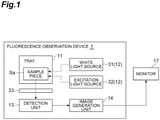
- FIG. 1 is a block diagram showing an embodiment of a fluorescence observation device.
- a fluorescence observation device 1 is configured as a device that performs fluorescence observation of a sample piece Sa cut out from a sample S (see FIG. 3 ).
- the fluorescence observation device 1 a stump examination of a tumor tissue excised from a patient by surgery will be illustrated. In the stump examination, a surface portion of the sample S is cut out into a plurality of the sample pieces Sa and the sample pieces Sa are stained with a fluorescence probe. A tumor tissue and a normal tissue have a different temporal behavior in fluorescence intensity. For this reason, it is possible to determine whether or not a tumor tissue remains in the sample piece Sa by measuring the fluorescence intensity of the sample piece Sa after a predetermined time elapses from the staining with the fluorescence probe.
- the fluorescence probe is a substance that changes its molecular structure by reacting with a specific substance and generates strong fluorescence.
- gGlu-HMRG As the fluorescence probe used in the stump examination, for example gGlu-HMRG can be exemplified.
- gGlu-HMRG is a liquid fluorescence substance. Before the reaction, gGlu-HMRG is colorless and transparent and exhibits water solubility.
- gGlu-HMRG that has reacted with an enzyme derived from a tumor tissue becomes colored and visualized. Further, gGlu-HMRG changes from water-soluble to hydrophobic and exhibits the property of penetrating a cell membrane and staying inside a cell. Thus, it is possible to highly accurately detect a minute tumor tissue of, for example, about several mm by using gGlu-HMRG.
- the fluorescence observation device 1 includes, as shown in FIG. 1 , a tray 11, a light source unit 12, a detection unit 13, and an image generation unit 14. These configurations are disposed in a housing 16 (see FIG. 2 ) that shields light from the outside. Further, the fluorescence observation device 1 is connected to a monitor 17 in a wired or wireless manner for information communication.
- the monitor 17 can be configured as a personal computer and a smart device (smartphone, tablet terminal).
- the tray 11 is a portion that places the sample piece Sa thereon.
- the tray 11 is formed of, for example, a resin in a substantially square plate shape in a plan view.
- the tray 11 preferably has a dark color such as black in order to ensure the sensitivity of fluorescence observation of the sample piece Sa.
- the tray 11 can be placed on a top surface of a drawer portion 18 provided at the lower portion of one side surface of the housing 16. By moving the drawer portion 18 in and out, the sample piece Sa placed on the tray 11 can be advanced and retracted with respect to the inspection position in the housing 16.
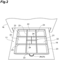
- one surface side of the tray 11 is provided with a center region 21 and a plurality of placement regions 22 provided around the center region 21.
- the center region 21 and the placement regions 22 are arranged in a matrix.
- the placement region 22 is disposed at eight positions around the center region 21 and eight sample pieces Sa can be observed simultaneously to maximum.
- the center region 21 and the placement region 22 both have a square shape and have equal areas with each other.
- the center region 21 and the placement region 22 are partitioned from each other by a partition member 23.
- the partition member 23 is formed of resin integrally with the main body of the tray 11.
- the partition member 23 is provided to surround the center region 21 and the placement region 22 with a predetermined prevention height in order to prevent the fluorescence probe applied to the sample piece Sa from flowing to the other placement region 22 and prevent the sample piece Sa of the other placement region 22 from being irradiated with the fluorescence generated from the sample piece Sa.
- the center region 21 is further divided into four divided regions 24 in a matrix.
- the divided region 24 is a region in which a reference plate (reference portion) R to be described later in FIG. 4 is disposed.
- the reference plate R is a plate-shaped member that generates fluorescence of reference intensity by irradiation of the excitation light.
- the fluorescence intensity of the reference plate R does not vary over time unlike the fluorescence intensity of the tumor tissue. For this reason, it is possible to perform highly accurate fluorescence observation even when the fluorescence intensity of the sample piece Sa slightly varies over time by referring to the fluorescence intensity of the reference plate R.
- the reference plate R is exemplified as the reference portion, but the shape of the reference portion is not particularly limited and may be other shapes such as a columnar shape and a block shape.
- the tray 11 includes a marker portion 25 which indicates a cutting orientation of the sample piece Sa with respect to the sample S.
- the marker portion 25 indicates an orientation of the sample piece Sa placed on each placement region 22 with respect to the sample S which is a cutout source.
- the marker portion 25 is configured as a protrusion portion 26 which protrudes laterally from one edge of the tray 11.
- the association between the protrusion portion 26 and the cutting orientation is arbitrary. For example, when the orientation indicated by the position of the protrusion portion 26 is "down”, the cutting orientation of the edge provided with the protrusion portion 26 is "down” and the cutting orientation of the edge opposite to the protrusion portion 26 with the center region 21 therebetween is “up”. Further, for example, the cutting orientation on the right side of the paper surface in FIG. 2 is “right” and the cutting orientation of the edge on the left side of the paper surface in FIG. 2 is “left".
- the planar shape of the protrusion portion 26 is a semicircular shape, but the planar shape of the protrusion portion 26 is arbitrary and may be a rectangular shape, a polygonal shape, or the like.
- the marker portion 25 is not limited to the protrusion portion 26 and other embodiments may be taken.
- the marker portion 25 may be formed by characters, symbols, colors, figures, a combination thereof, and the like in addition to the protrusion portion 26.
- the light source unit 12 includes a white light source 31 and an excitation light source 32.
- the white light source 31 and the excitation light source 32 are disposed above the arrangement position of the tray 11 in the housing 16.
- the white light source 31 is configured as, for example, a lamp or the like and irradiates the sample piece Sa on the tray 11 with white light from above.
- the excitation light source 32 is configured as, for example, an LED or the like and irradiates the sample piece Sa on the tray 11 with the excitation light from above.
- the detection unit 13 includes, for example, an imaging element such as a CCD image sensor or a CMOS image sensor.
- the detection unit 13 is disposed above the arrangement position of the tray 11 in the housing 16.
- a detection surface (not shown) of the detection unit 13 is disposed downward to face the tray 11.
- the detection unit 13 may include an optical filter 33 which transmits fluorescence of a wavelength generated by the sample piece Sa.
- the detection unit 13 outputs a detection signal indicating an imaging result of the sample piece Sa by white light and a detection signal indicating an imaging result of fluorescence generated in the sample piece Sa by the irradiation of the excitation light to the image generation unit 14.
- the image generation unit 14 is configured as, for example, a microcomputer including a processor and a memory, a field-programmable gate array (FPGA), or the like.
- the image generation unit 14 generates a fluorescence image of the sample piece Sa based on the detection signal from the detection unit 13.
- the image generation unit 14 generates a visible image based on a detection signal indicating an imaging result of the sample piece Sa by white light and generates a fluorescence image based on a detection signal indicating an imaging result of the fluorescence generated in the sample piece Sa.
- the image generation unit 14 generates a superimposed imaged in which the visible image and the fluorescence image are superimposed and outputs the superimposed image to the monitor 17.
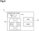
- the image generation unit 14 generates a result image (see FIG. 6 ) G in which the fluorescence observation result of the sample piece Sa and the placement region 22 are associated with each other and outputs the result image to the monitor 17.
- the image generation unit 14 may have a function of performing shading correction of the fluorescence image (superimposed image).
- the image generation unit 14 holds in advance a brightness distribution for detecting the fluorescence in the detection unit 13 based on, for example, the imaging result of the reference plate having the same area as that of the tray 11 and performs shading correction of the fluorescence image (superimposed image) based on the brightness distribution.
- shading correction it is possible to cancel the influence of the fluorescence brightness distribution caused by the configuration of the detection unit 13 and improve the accuracy of the fluorescence observation.
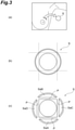
- FIG. 3(a) a tumor tissue is excised from the patient by surgery and this is used as the sample S.
- FIG. 3(b) a surface portion of the sample S is cut out with a knife or the like to prepare a plurality of sample pieces SaA to SaD as shown in FIG. 3(c) .
- a cutting orientation of the sample S to the up, down, right, and left sides is determined in relation to a human body from which a sample is excised.
- the orientation of the sample piece SaA is "down"
- the orientation of the sample piece SaB is "up”
- the orientation of the sample piece SaC is "right”
- the orientation of the sample piece SaD is "left".
- the sample piece Sa is set in the tray 11.
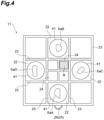
- each sample piece Sa is disposed in a dish 41 of a bottomed cylinder and the sample piece Sa is disposed on the placement region 22 with the dish 41 therebetween.
- the sample pieces SaA to SaD are arranged to correspond to the cutting orientation indicated by the marker portion 25 of the tray 11. That is, the sample piece SaA is placed on the placement region 22 at the center on the edge side provided with the protrusion portion 26 and the sample piece SaB is placed on the placement region 22 at the center on the edge side opposite to the protrusion portion 26 with the center region 21 therebetween.
- the sample piece SaC is placed on the placement region 22 at the center on the right edge side of the paper surface in FIG. 4 and the sample piece SaD is placed on the placement region 22 at the center on the left edge side of the paper surface in FIG. 4 .
- a cutout surface P (see FIG. 3(c) ) is directed upward (the side of the detection unit 13).
- the outermost surface portion of the sample S (see FIGS. 3(b) and 3(c) ) may have degenerated tissue due to the influence of an electric knife used in the surgery and almost no reaction to the fluorescence probe occurs. For this reason, the cutout surface P of the sample piece Sa becomes the stump of the observation target.
- the reference plate R is disposed on the center region 21.
- the arrangement position of the reference plate R in the divided region 24 is arbitrary. That is, the reference plate R may be disposed in any one of four divided regions 24.
- each sample piece Sa is stained with the fluorescence probe and the tray 11 is placed on the top surface of the drawer portion 18.
- the drawer portion 18 is accommodated in the housing 16 and is advanced to an inspection position in the housing 16 of the sample piece Sa placed on the tray 11. Subsequently, the sample piece Sa is irradiated with white light and excitation light from the light source unit 12 and fluorescence generated in the sample piece Sa by the irradiation of the excitation light is detected.
- a superimposed image is generated by superimposing a visible image generated based on a detection signal indicating an imaging result of the sample piece Sa due to the white light and a fluorescence image generated based on a detection signal indicating an fluorescence imaging result generated in the sample piece Sa and the superimposed image is output to the monitor 17. Further, a result image in which a fluorescence observation result of the sample piece Sa is associated with the placement region 22 is output to the monitor 17. Additionally, the autofluorescence of the sample piece Sa may be detected before staining with the fluorescence probe and the autofluorescence intensity may be corrected to detect the fluorescence intensity.
- FIG. 5 is a graph showing a detection example of a temporal behavior of the fluorescence intensity in the tumor tissue and the normal tissue.
- a horizontal axis indicates the time (the elapse time after staining with the fluorescence probe) and a vertical axis indicates the fluorescence intensity.
- the fluorescence intensity tends to gradually increase over time in the tumor tissue.
- FIG. 6 is a diagram showing a display example of a result image.
- the result image G includes, for example, a region Ga in which a stump examination ID and the like are displayed, a region Gb in which a figure corresponding to the placement region 22 of the tray 11 is displayed, and a region Gc in which a command for the result image G is displayed.
- the region Ga for example, the date and time of the inspection, the name of the person to be inspected, the ID, and the like are displayed.
- the fluorescence observation result of the sample piece Sa and the placement region 22 are displayed in association with each other.
- color coding based on whether the observation result is positive or negative, a mark indicating the degree of positive, and the like are displayed in addition to the numerical value indicating the fluorescence intensity.
- a command to close the result image G, a print command, and the like are displayed.
- the sample piece Sa which is determined to be positive is selected and submitted to a pathologist in association with the cutting orientation. Accordingly, it is possible to screen only the sample piece Sa which is determined to be positive from the plurality of sample pieces Sa and easily identify a positional relationship between the sample piece Sa which is determined to be positive and the sample S (that is, a surgical site of a patient) which is a cutout source.
- the fluorescence image is generated based on the fluorescence from the sample piece Sa.
- the plurality of placement regions 22 on which the sample pieces Sa are placed are provided around the center region 21 of the tray 11 and the marker portion 25 indicating the cutting orientation of the sample piece Sa with respect to the sample S is provided therein.
- the tray 11 includes the reference plate R which generates fluorescence having reference intensity by irradiation of the excitation light.
- the reference plate R is provided in the center region 21. Accordingly, it is possible to efficiently use the space of the tray 11.
- the plurality of placement regions 22 of the tray are partitioned from each other by the partition member 23. Accordingly, it is possible to prevent the fluorescence probe applied to the sample piece Sa from flowing to the other placement region 22. Further, it is possible to prevent the sample piece Sa of the other placement region 22 from being irradiated with the fluorescence generated from the sample piece Sa.
- the image generation unit 14 has a brightness distribution for detecting the fluorescence in the detection unit 13 and performs shading correction of the fluorescence image based on the brightness distribution. Accordingly, it is possible to observe the sample piece Sa based on the clear fluorescence image. Further, in this embodiment, the image generation unit 14 generates the result image G in which the fluorescence observation result of the sample piece Sa is associated with the placement region 22. Accordingly, it is possible to visually recognize the observation result and further improve the observation speed.
- the sample piece Sa is placed on the dish 41, but a fixing portion F for fixing the sample piece Sa to the dish 41 may be provided.
- the fixing portion F is configured as a dish 51 provided with a bottom surface 51a having a mesh shape.
- This dish 51 has an outer diameter that is one size smaller than the inner diameter of the dish 41 on which the sample piece Sa is placed. In this case, it is possible to fix the sample piece Sa to the dish 41 by pressing the bottom surface 51a having a mesh shape against the sample piece Sa in the dish 41.
- the fixing portion F is configured as a plurality of fine needles 52 provided on the bottom surface of the dish 41. In this case, it is possible to fix the sample piece Sa to the dish 41 by inserting the sample piece Sa into the needle 52. It is easy to handle the sample piece Sa by providing the fixing portion F in the dish 41. Although a case is supposed in which the attitude of the sample piece Sa is changed due to the buoyancy received from the fluorescence probe during the fluorescence observation, it is possible to prevent the misalignment, inversion, and the like of the sample piece Sa during the fluorescence observation by using the fixing portion F.
- a stamp jig 61 shown in FIGS. 8(a) and 8(b) may be used together with the fixing portion F.
- the stamp jig 61 includes a tubular portion 62 which includes a bottom surface 62a having a mesh shape, a leg portion 63 which is provided in the edge of the bottom surface 62a, and a rod-shaped grip portion 64 which is provided at the center of a top surface 62b of the tubular portion 62.
- the sample piece Sa is placed on the placement region 22 of the tray 11 through the dish 41, but the sample piece Sa may be directly placed on the tray 11 without using the dish 41.
- the above-described needle 52 may be directly provided on the surface of the tray 11.
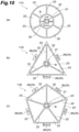
- FIGS. 9 and 10 are plan views showing modified examples of the tray.
- the placement regions 22 are provided in a matrix as in FIG. 1 and the center region 21 is also the placement region 22 for the sample piece Sa.
- an overhanging portion 27 for placing the reference plate R is provided in the edge on the side opposite to the protrusion portion 26 which is the marker portion 25. This overhanging portion 27 also functions as the marker portion 25.
- a tray 11B shown in FIG. 9(b) four rectangular placement regions 22 are provided around the center region 21.
- the protrusion portion 26 which is the marker portion 25 is also provided in the right and left edges of the paper surface and the cutting orientation of the sample piece Sa can be more easily recognized.
- the planar shape of a tray 11C shown in FIG. 10(a) is a circular shape.
- the center region 21 has a circular shape and six arc-shaped placement regions 22 are arranged around the center region 21.
- the reference plate R is disposed in the center region 21.
- characters such as "TOP”, “Bottom”, “Left”, and “Right” are attached as the marker portion 25 around the arrangement region of the reference plate R.
- the planar shape of a tray 11D shown in FIG. 10(b) is an equilateral triangle. In the tray 11D, the shape of the center region 21 is circular and three isosceles triangle-shaped placement regions 22 are arranged around the center region 21.
- the reference plate R is disposed in the center region 21.
- the protrusion portions 26 are provided in the edges corresponding to the sides of the tray 11D. Characters such as “Bottom”, “Left”, and “Right” are attached as the marker portion 25 in the protrusion portion 26.
- the planar shape of a tray 11E shown in FIG. 10(c) is a regular pentagonal shape. In the tray 11E, the shape of the center region 21 is circular and five equilateral triangular placement regions 22 are arranged around the center region 21.
- the reference plate R is disposed in the center region 21.
- the protrusion portions 26 are provided in the edges corresponding to the sides of the tray 11E. In the protrusion portion 26, characters such as “Bottom”, “Left”, and “Right” are attached as the marker portion 25.
- the trays 11A to 11E it is possible to easily identify a positional relationship between the sample piece Sa which is cut out from the sample S and the sample S which is a cutout source by the arrangement of the placement region 22 and the marker portion 25. Further, it is easy to handle the sample piece Sa when performing fluorescence observation by providing the placement regions 22 as many as the cut-out sample pieces Sa.
Landscapes
- Health & Medical Sciences (AREA)
- Immunology (AREA)
- Physics & Mathematics (AREA)
- Life Sciences & Earth Sciences (AREA)
- Chemical & Material Sciences (AREA)
- General Physics & Mathematics (AREA)
- Biochemistry (AREA)
- General Health & Medical Sciences (AREA)
- Analytical Chemistry (AREA)
- Nuclear Medicine, Radiotherapy & Molecular Imaging (AREA)
- Pathology (AREA)
- Chemical Kinetics & Catalysis (AREA)
- Optics & Photonics (AREA)
- Engineering & Computer Science (AREA)
- Biomedical Technology (AREA)
- Molecular Biology (AREA)
- Investigating, Analyzing Materials By Fluorescence Or Luminescence (AREA)
- Microscoopes, Condenser (AREA)
Abstract
Description
- The present disclosure relates to a fluorescence observation device.
- As a conventional fluorescence observation device, for example, an identification device described in
Patent Literature 1 is known. This conventional identification device is a device that spectroscopically detects the fluorescence of protoporphyrins existing at a tumor site of a subject. Protoporphyrins are protoporphyrin IX (PpIX) and photo-protoporphyrin (PPp). The identification device includes a light irradiation unit which converts a part of PpIX into PPp, a spectroscopic unit which disperses the fluorescence of PpIX and the fluorescence of PPp, a spectroscopic detection unit which detects a relative fluorescence intensity between the fluorescence of PpIX and the fluorescence of PPp, and a tumor discrimination unit which discriminates a tumor site and a normal site based on the relative fluorescence intensity between PpIX and PPp. - Patent Literature 1:
Japanese Patent No. 5991975 - When surgery is performed to excise a tumor, a postoperative stump examination is performed to see if a tumor tissue remains in a surgical site. A sample of the stump examination is a tissue excised by surgery and includes a tumor tissue and a normal tissue around the tumor tissue. In the stump examination, a surface portion of the sample is cut out into a plurality of sample pieces and the sample pieces are stained with a fluorescence probe. The tumor tissue and the normal tissue have a different temporal behavior in fluorescence intensity. For this reason, it is possible to determine whether or not a tumor tissue remains in the sample piece by measuring the fluorescence intensity of the sample piece after a predetermined time elapses from the staining with the fluorescence probe. When the tumor tissue does not remain in the sample piece, it is determined that the tumor tissue does not remain in the surgical site.
- The determination on whether or not the tumor tissue remains by the stump examination is performed by, for example, a pathologist. However, since a pathologist observes a sample piece with a microscope after making a pathological sample at present, it is required to improve the observation speed and the observation accuracy. Further, when the tumor tissue remains in the sample piece, a method of easily identifying a positional relationship between the residual site of the tumor tissue in the sample and the surgical site of the patient is necessary in order to appropriately administer additional treatment to the patient.
- The present disclosure has been made to solve the above-described problems and an object of the present disclosure is to provide a fluorescence observation device capable of improving observation speed and observation accuracy and easily identifying a positional relationship between a sample piece and a sample which is a cutout source.
- A fluorescence observation device according to an aspect of the present disclosure is a fluorescence observation device for performing fluorescence observation of a sample piece cut out from a sample including: a tray on which the sample piece is placed; a light source unit which generates excitation light to irradiate the sample piece; a detection unit which detects fluorescence from the sample piece; and an image generation unit which generates a fluorescence image of the sample piece based on a detection signal from the detection unit, wherein the tray includes a plurality of placement regions provided around a center region of the tray and also includes a marker portion indicating a cutting orientation of the sample piece with respect to the sample.
- In this fluorescence observation device, the fluorescence image is generated based on the fluorescence from the sample piece. By the observation of the fluorescence image, the observation speed and the observation accuracy are improved as compared with the case of observing the fluorescence of the sample piece with the microscope. Further, in this fluorescence observation device, the plurality of placement regions on which the sample pieces are placed are provided around the center region of the tray and the marker portion indicating the cutting orientation of the sample piece with respect to the sample is provided therein. By the arrangement of these placement regions and the marker portion, it is possible to easily identify a positional relationship between the sample piece cut out from the sample and the sample which is a cutout source.
- The tray may include a reference portion which generates fluorescence of reference intensity by irradiation with the excitation light. By referring to the reference intensity of the fluorescence, it is possible to sufficiently ensure the observation accuracy even when the fluorescence intensity of the sample piece slightly varies over time.
- The reference portion may be provided in the center region. In this case, it is possible to efficiently use the space of the tray.
- The plurality of placement regions may be partitioned from each other by a partition member. In this case, it is possible to prevent the fluorescence probe applied to the sample piece from flowing to the other placement region. Further, it is possible to prevent the sample piece of the other placement region from being irradiated with the fluorescence generated from the sample piece.
- The placement region may be provided with a fixing portion which fixes the sample piece. In this case, it is possible to prevent the misalignment, inversion, and the like of the sample piece during fluorescence observation using the fixing portion.
- The fluorescence observation device may further include a dish which is disposed on the placement region and the dish may be provided with a fixing portion which fixes the sample piece. It is easy to handle the sample piece by using the dish. Further, it is possible to prevent the misalignment, inversion, and the like of the sample piece during fluorescence observation using the fixing portion.
- The image generation unit may have a brightness distribution for detecting the fluorescence in the detection unit and perform shading correction of the fluorescence image based on the brightness distribution. In this case, it is possible to observe the sample piece based on a clearer fluorescence image.
- The image generation unit may generate a result image in which a fluorescence observation result of the sample piece is associated with the placement region. Accordingly, it is possible to visually recognize the observation result and further improve the observation speed.
- According to the present disclosure, it is possible to improve observation speed and observation accuracy and easily identify a positional relationship between a sample piece and a sample which is a cutout source.
-
-
FIG. 1 is a block diagram showing an embodiment of a fluorescence observation device. -
FIG. 2 is a perspective view showing an example of a tray applied to the fluorescence observation device. -
FIG. 3 is a schematic view showing a preparation of a sample and a sample piece. -
FIG. 4 is a plan view showing a placement example of the sample piece on the tray. -
FIG. 5 is a graph showing a detection example of a temporal behavior of fluorescence intensity in a tumor tissue and a normal tissue. -
FIG. 6 is a diagram showing a display example of a result image. -
FIG. 7 is a schematic perspective view showing an example of a fixing portion for fixing the sample piece. -
FIG. 8 is a perspective view showing an example of a stamp jig used in combination with the fixing portion. -
FIG. 9 is a plan view showing a modified example of the tray. -
FIG. 10 is a plan view showing another modified example of the tray. - Hereinafter, a preferred embodiment of a fluorescence observation device according to an aspect of the present disclosure will be described in detail with reference to the drawings.
-
FIG. 1 is a block diagram showing an embodiment of a fluorescence observation device. Afluorescence observation device 1 is configured as a device that performs fluorescence observation of a sample piece Sa cut out from a sample S (seeFIG. 3 ). In this embodiment, as an application example of thefluorescence observation device 1, a stump examination of a tumor tissue excised from a patient by surgery will be illustrated. In the stump examination, a surface portion of the sample S is cut out into a plurality of the sample pieces Sa and the sample pieces Sa are stained with a fluorescence probe. A tumor tissue and a normal tissue have a different temporal behavior in fluorescence intensity. For this reason, it is possible to determine whether or not a tumor tissue remains in the sample piece Sa by measuring the fluorescence intensity of the sample piece Sa after a predetermined time elapses from the staining with the fluorescence probe. - The fluorescence probe is a substance that changes its molecular structure by reacting with a specific substance and generates strong fluorescence. As the fluorescence probe used in the stump examination, for example gGlu-HMRG can be exemplified. gGlu-HMRG is a liquid fluorescence substance. Before the reaction, gGlu-HMRG is colorless and transparent and exhibits water solubility. gGlu-HMRG that has reacted with an enzyme derived from a tumor tissue becomes colored and visualized. Further, gGlu-HMRG changes from water-soluble to hydrophobic and exhibits the property of penetrating a cell membrane and staying inside a cell. Thus, it is possible to highly accurately detect a minute tumor tissue of, for example, about several mm by using gGlu-HMRG.
- The
fluorescence observation device 1 includes, as shown inFIG. 1 , atray 11, alight source unit 12, adetection unit 13, and animage generation unit 14. These configurations are disposed in a housing 16 (seeFIG. 2 ) that shields light from the outside. Further, thefluorescence observation device 1 is connected to amonitor 17 in a wired or wireless manner for information communication. Themonitor 17 can be configured as a personal computer and a smart device (smartphone, tablet terminal). - The
tray 11 is a portion that places the sample piece Sa thereon. As shown inFIG. 2 , thetray 11 is formed of, for example, a resin in a substantially square plate shape in a plan view. Thetray 11 preferably has a dark color such as black in order to ensure the sensitivity of fluorescence observation of the sample piece Sa. For example, thetray 11 can be placed on a top surface of adrawer portion 18 provided at the lower portion of one side surface of thehousing 16. By moving thedrawer portion 18 in and out, the sample piece Sa placed on thetray 11 can be advanced and retracted with respect to the inspection position in thehousing 16. - As shown in
FIG. 2 , one surface side of thetray 11 is provided with acenter region 21 and a plurality ofplacement regions 22 provided around thecenter region 21. In this embodiment, thecenter region 21 and theplacement regions 22 are arranged in a matrix. In this embodiment, theplacement region 22 is disposed at eight positions around thecenter region 21 and eight sample pieces Sa can be observed simultaneously to maximum. Thecenter region 21 and theplacement region 22 both have a square shape and have equal areas with each other. - Further, the
center region 21 and theplacement region 22 are partitioned from each other by apartition member 23. Thepartition member 23 is formed of resin integrally with the main body of thetray 11. Thepartition member 23 is provided to surround thecenter region 21 and theplacement region 22 with a predetermined prevention height in order to prevent the fluorescence probe applied to the sample piece Sa from flowing to theother placement region 22 and prevent the sample piece Sa of theother placement region 22 from being irradiated with the fluorescence generated from the sample piece Sa. - In this embodiment, the
center region 21 is further divided into four dividedregions 24 in a matrix. The dividedregion 24 is a region in which a reference plate (reference portion) R to be described later inFIG. 4 is disposed. The reference plate R is a plate-shaped member that generates fluorescence of reference intensity by irradiation of the excitation light. The fluorescence intensity of the reference plate R does not vary over time unlike the fluorescence intensity of the tumor tissue. For this reason, it is possible to perform highly accurate fluorescence observation even when the fluorescence intensity of the sample piece Sa slightly varies over time by referring to the fluorescence intensity of the reference plate R. In this embodiment, the reference plate R is exemplified as the reference portion, but the shape of the reference portion is not particularly limited and may be other shapes such as a columnar shape and a block shape. - The
tray 11 includes amarker portion 25 which indicates a cutting orientation of the sample piece Sa with respect to the sample S. For example, when thecenter region 21 is regarded as the center portion of the sample S, themarker portion 25 indicates an orientation of the sample piece Sa placed on eachplacement region 22 with respect to the sample S which is a cutout source. In this embodiment, themarker portion 25 is configured as aprotrusion portion 26 which protrudes laterally from one edge of thetray 11. The association between theprotrusion portion 26 and the cutting orientation is arbitrary. For example, when the orientation indicated by the position of theprotrusion portion 26 is "down", the cutting orientation of the edge provided with theprotrusion portion 26 is "down" and the cutting orientation of the edge opposite to theprotrusion portion 26 with thecenter region 21 therebetween is "up". Further, for example, the cutting orientation on the right side of the paper surface inFIG. 2 is "right" and the cutting orientation of the edge on the left side of the paper surface inFIG. 2 is "left". - In the example of
FIG. 2 , the planar shape of theprotrusion portion 26 is a semicircular shape, but the planar shape of theprotrusion portion 26 is arbitrary and may be a rectangular shape, a polygonal shape, or the like. Themarker portion 25 is not limited to theprotrusion portion 26 and other embodiments may be taken. For example themarker portion 25 may be formed by characters, symbols, colors, figures, a combination thereof, and the like in addition to theprotrusion portion 26. - As shown in
FIG. 1 , thelight source unit 12 includes awhite light source 31 and anexcitation light source 32. For example, thewhite light source 31 and theexcitation light source 32 are disposed above the arrangement position of thetray 11 in thehousing 16. Thewhite light source 31 is configured as, for example, a lamp or the like and irradiates the sample piece Sa on thetray 11 with white light from above. Further, theexcitation light source 32 is configured as, for example, an LED or the like and irradiates the sample piece Sa on thetray 11 with the excitation light from above. - The
detection unit 13 includes, for example, an imaging element such as a CCD image sensor or a CMOS image sensor. For example, thedetection unit 13 is disposed above the arrangement position of thetray 11 in thehousing 16. A detection surface (not shown) of thedetection unit 13 is disposed downward to face thetray 11. If necessary, thedetection unit 13 may include anoptical filter 33 which transmits fluorescence of a wavelength generated by the sample piece Sa. Thedetection unit 13 outputs a detection signal indicating an imaging result of the sample piece Sa by white light and a detection signal indicating an imaging result of fluorescence generated in the sample piece Sa by the irradiation of the excitation light to theimage generation unit 14. - The
image generation unit 14 is configured as, for example, a microcomputer including a processor and a memory, a field-programmable gate array (FPGA), or the like. Theimage generation unit 14 generates a fluorescence image of the sample piece Sa based on the detection signal from thedetection unit 13. In this embodiment, theimage generation unit 14 generates a visible image based on a detection signal indicating an imaging result of the sample piece Sa by white light and generates a fluorescence image based on a detection signal indicating an imaging result of the fluorescence generated in the sample piece Sa. Then, theimage generation unit 14 generates a superimposed imaged in which the visible image and the fluorescence image are superimposed and outputs the superimposed image to themonitor 17. Further, theimage generation unit 14 generates a result image (seeFIG. 6 ) G in which the fluorescence observation result of the sample piece Sa and theplacement region 22 are associated with each other and outputs the result image to themonitor 17. - The
image generation unit 14 may have a function of performing shading correction of the fluorescence image (superimposed image). In this case, theimage generation unit 14 holds in advance a brightness distribution for detecting the fluorescence in thedetection unit 13 based on, for example, the imaging result of the reference plate having the same area as that of thetray 11 and performs shading correction of the fluorescence image (superimposed image) based on the brightness distribution. By performing shading correction, it is possible to cancel the influence of the fluorescence brightness distribution caused by the configuration of thedetection unit 13 and improve the accuracy of the fluorescence observation. - Next, a fluorescence observation method using the above-described
fluorescence observation device 1 will be described. Here, the above-described stump examination will be illustrated. In the stump examination, first, as shown inFIG. 3(a) , a tumor tissue is excised from the patient by surgery and this is used as the sample S. Next, as shown inFIG. 3(b) , a surface portion of the sample S is cut out with a knife or the like to prepare a plurality of sample pieces SaA to SaD as shown inFIG. 3(c) . In the sample pieces SaA to SaD, a cutting orientation of the sample S to the up, down, right, and left sides is determined in relation to a human body from which a sample is excised. In the example ofFIG. 3(c) , the orientation of the sample piece SaA is "down", the orientation of the sample piece SaB is "up", the orientation of the sample piece SaC is "right", and the orientation of the sample piece SaD is "left". - After preparing the sample piece Sa, as shown in
FIG. 4 , the sample piece Sa is set in thetray 11. In the example ofFIG. 4 , each sample piece Sa is disposed in adish 41 of a bottomed cylinder and the sample piece Sa is disposed on theplacement region 22 with thedish 41 therebetween. Regarding the arrangement of the sample piece Sa in theplacement region 22, the sample pieces SaA to SaD are arranged to correspond to the cutting orientation indicated by themarker portion 25 of thetray 11. That is, the sample piece SaA is placed on theplacement region 22 at the center on the edge side provided with theprotrusion portion 26 and the sample piece SaB is placed on theplacement region 22 at the center on the edge side opposite to theprotrusion portion 26 with thecenter region 21 therebetween. Further, the sample piece SaC is placed on theplacement region 22 at the center on the right edge side of the paper surface inFIG. 4 and the sample piece SaD is placed on theplacement region 22 at the center on the left edge side of the paper surface inFIG. 4 . - Further, regarding the arrangement of the sample piece Sa in the
placement region 22, a cutout surface P (seeFIG. 3(c) ) is directed upward (the side of the detection unit 13). The outermost surface portion of the sample S (seeFIGS. 3(b) and 3(c) ) may have degenerated tissue due to the influence of an electric knife used in the surgery and almost no reaction to the fluorescence probe occurs. For this reason, the cutout surface P of the sample piece Sa becomes the stump of the observation target. The reference plate R is disposed on thecenter region 21. The arrangement position of the reference plate R in the dividedregion 24 is arbitrary. That is, the reference plate R may be disposed in any one of four dividedregions 24. - After the sample piece Sa is set in the
tray 11, each sample piece Sa is stained with the fluorescence probe and thetray 11 is placed on the top surface of thedrawer portion 18. Next, thedrawer portion 18 is accommodated in thehousing 16 and is advanced to an inspection position in thehousing 16 of the sample piece Sa placed on thetray 11. Subsequently, the sample piece Sa is irradiated with white light and excitation light from thelight source unit 12 and fluorescence generated in the sample piece Sa by the irradiation of the excitation light is detected. Then, a superimposed image is generated by superimposing a visible image generated based on a detection signal indicating an imaging result of the sample piece Sa due to the white light and a fluorescence image generated based on a detection signal indicating an fluorescence imaging result generated in the sample piece Sa and the superimposed image is output to themonitor 17. Further, a result image in which a fluorescence observation result of the sample piece Sa is associated with theplacement region 22 is output to themonitor 17. Additionally, the autofluorescence of the sample piece Sa may be detected before staining with the fluorescence probe and the autofluorescence intensity may be corrected to detect the fluorescence intensity. -
FIG. 5 is a graph showing a detection example of a temporal behavior of the fluorescence intensity in the tumor tissue and the normal tissue. InFIG. 5 , a horizontal axis indicates the time (the elapse time after staining with the fluorescence probe) and a vertical axis indicates the fluorescence intensity. As shown inFIG. 5 , there is almost no variation in fluorescence intensity over time in the normal tissue and the fluorescence intensity tends to gradually increase over time in the tumor tissue. Thus, it is possible to determine whether or not the sample piece Sa contains the tumor tissue by comparing the fluorescence intensity after a predetermined time elapses with a predetermined threshold value. -
FIG. 6 is a diagram showing a display example of a result image. In the example of the same drawing, the result image G includes, for example, a region Ga in which a stump examination ID and the like are displayed, a region Gb in which a figure corresponding to theplacement region 22 of thetray 11 is displayed, and a region Gc in which a command for the result image G is displayed. In the region Ga, for example, the date and time of the inspection, the name of the person to be inspected, the ID, and the like are displayed. In the region Gb, the fluorescence observation result of the sample piece Sa and theplacement region 22 are displayed in association with each other. Here, color coding based on whether the observation result is positive or negative, a mark indicating the degree of positive, and the like are displayed in addition to the numerical value indicating the fluorescence intensity. In the region Gc, a command to close the result image G, a print command, and the like are displayed. - When the sample pieces Sa contain a positive determination result, the sample piece Sa which is determined to be positive is selected and submitted to a pathologist in association with the cutting orientation. Accordingly, it is possible to screen only the sample piece Sa which is determined to be positive from the plurality of sample pieces Sa and easily identify a positional relationship between the sample piece Sa which is determined to be positive and the sample S (that is, a surgical site of a patient) which is a cutout source.
- As described above, in the
fluorescence observation device 1, the fluorescence image is generated based on the fluorescence from the sample piece Sa. By the observation of the fluorescence image, it is possible to improve the observation speed and the observation accuracy as compared with a case in which the fluorescence of the sample piece Sa is observed with a microscope. Further, in thefluorescence observation device 1, the plurality ofplacement regions 22 on which the sample pieces Sa are placed are provided around thecenter region 21 of thetray 11 and themarker portion 25 indicating the cutting orientation of the sample piece Sa with respect to the sample S is provided therein. By the arrangement of theplacement regions 22 and themarker portion 25, it is possible to easily identify a positional relationship between the sample piece Sa which is cut out from the sample S and the sample S which is a cutout source. - In this embodiment, the
tray 11 includes the reference plate R which generates fluorescence having reference intensity by irradiation of the excitation light. By referring to the reference intensity of the fluorescence, it is possible to sufficiently ensure the observation accuracy even when the fluorescence intensity of the sample piece Sa slightly varies over time. Further, in this embodiment, the reference plate R is provided in thecenter region 21. Accordingly, it is possible to efficiently use the space of thetray 11. - In this embodiment, the plurality of
placement regions 22 of the tray are partitioned from each other by thepartition member 23. Accordingly, it is possible to prevent the fluorescence probe applied to the sample piece Sa from flowing to theother placement region 22. Further, it is possible to prevent the sample piece Sa of theother placement region 22 from being irradiated with the fluorescence generated from the sample piece Sa. - In this embodiment, the
image generation unit 14 has a brightness distribution for detecting the fluorescence in thedetection unit 13 and performs shading correction of the fluorescence image based on the brightness distribution. Accordingly, it is possible to observe the sample piece Sa based on the clear fluorescence image. Further, in this embodiment, theimage generation unit 14 generates the result image G in which the fluorescence observation result of the sample piece Sa is associated with theplacement region 22. Accordingly, it is possible to visually recognize the observation result and further improve the observation speed. - The present disclosure can be modified into various forms. For example, in the above-described embodiment, the sample piece Sa is placed on the
dish 41, but a fixing portion F for fixing the sample piece Sa to thedish 41 may be provided. In the example ofFIG. 7(a) , the fixing portion F is configured as adish 51 provided with abottom surface 51a having a mesh shape. Thisdish 51 has an outer diameter that is one size smaller than the inner diameter of thedish 41 on which the sample piece Sa is placed. In this case, it is possible to fix the sample piece Sa to thedish 41 by pressing thebottom surface 51a having a mesh shape against the sample piece Sa in thedish 41. - In the example of
FIG. 7(b) , the fixing portion F is configured as a plurality offine needles 52 provided on the bottom surface of thedish 41. In this case, it is possible to fix the sample piece Sa to thedish 41 by inserting the sample piece Sa into theneedle 52. It is easy to handle the sample piece Sa by providing the fixing portion F in thedish 41. Although a case is supposed in which the attitude of the sample piece Sa is changed due to the buoyancy received from the fluorescence probe during the fluorescence observation, it is possible to prevent the misalignment, inversion, and the like of the sample piece Sa during the fluorescence observation by using the fixing portion F. - Further, a
stamp jig 61 shown inFIGS. 8(a) and 8(b) may be used together with the fixing portion F. For example, thestamp jig 61 includes atubular portion 62 which includes abottom surface 62a having a mesh shape, aleg portion 63 which is provided in the edge of thebottom surface 62a, and a rod-shapedgrip portion 64 which is provided at the center of atop surface 62b of thetubular portion 62. When the mesh-shapedbottom surface 62a is pressed against the sample piece Sa using thestamp jig 61, it is possible to define a force of pressing the sample piece Sa based on the length of theleg portion 63. Thus, it is possible to prevent the damage of the sample piece Sa due to the addition of an excessive pressing force. - In the above-described embodiment, the sample piece Sa is placed on the
placement region 22 of thetray 11 through thedish 41, but the sample piece Sa may be directly placed on thetray 11 without using thedish 41. When the fixing portion F is used in this configuration, the above-describedneedle 52 may be directly provided on the surface of thetray 11. -
FIGS. 9 and10 are plan views showing modified examples of the tray. In atray 11A shown inFIG. 9(a) , theplacement regions 22 are provided in a matrix as inFIG. 1 and thecenter region 21 is also theplacement region 22 for the sample piece Sa. In thetray 11A, an overhangingportion 27 for placing the reference plate R is provided in the edge on the side opposite to theprotrusion portion 26 which is themarker portion 25. This overhangingportion 27 also functions as themarker portion 25. In atray 11B shown inFIG. 9(b) , fourrectangular placement regions 22 are provided around thecenter region 21. In thetray 11B, theprotrusion portion 26 which is themarker portion 25 is also provided in the right and left edges of the paper surface and the cutting orientation of the sample piece Sa can be more easily recognized. - The planar shape of a tray 11C shown in
FIG. 10(a) is a circular shape. In the tray 11C, thecenter region 21 has a circular shape and six arc-shapedplacement regions 22 are arranged around thecenter region 21. The reference plate R is disposed in thecenter region 21. Further, in thecenter region 21, characters such as "TOP", "Bottom", "Left", and "Right" are attached as themarker portion 25 around the arrangement region of the reference plate R. The planar shape of atray 11D shown inFIG. 10(b) is an equilateral triangle. In thetray 11D, the shape of thecenter region 21 is circular and three isosceles triangle-shapedplacement regions 22 are arranged around thecenter region 21. The reference plate R is disposed in thecenter region 21. Theprotrusion portions 26 are provided in the edges corresponding to the sides of thetray 11D. Characters such as "Bottom", "Left", and "Right" are attached as themarker portion 25 in theprotrusion portion 26. The planar shape of atray 11E shown inFIG. 10(c) is a regular pentagonal shape. In thetray 11E, the shape of thecenter region 21 is circular and five equilateraltriangular placement regions 22 are arranged around thecenter region 21. The reference plate R is disposed in thecenter region 21. Theprotrusion portions 26 are provided in the edges corresponding to the sides of thetray 11E. In theprotrusion portion 26, characters such as "Bottom", "Left", and "Right" are attached as themarker portion 25. - Also in the
trays 11A to 11E according to these modified examples, it is possible to easily identify a positional relationship between the sample piece Sa which is cut out from the sample S and the sample S which is a cutout source by the arrangement of theplacement region 22 and themarker portion 25. Further, it is easy to handle the sample piece Sa when performing fluorescence observation by providing theplacement regions 22 as many as the cut-out sample pieces Sa. - 1: fluorescence observation device, 11, 11A to 11E: tray, 12: light source unit, 13: detection unit, 14: image generation unit, 21: center region, 22: placement region, 23: partition member, 25: marker portion, 41: dish, F: fixing portion, G: result image, R: reference plate (reference portion), S: sample, Sa: sample piece.
Claims (8)
- A fluorescence observation device for performing fluorescence observation of a sample piece cut out from a sample comprising:a tray on which the sample piece is placed;a light source unit which generates excitation light to irradiate the sample piece;a detection unit which detects fluorescence from the sample piece; andan image generation unit which generates a fluorescence image of the sample piece based on a detection signal from the detection unit,wherein the tray includes a plurality of placement regions provided around a center region of the tray and also includes a marker portion indicating a cutting orientation of the sample piece with respect to the sample.
- The fluorescence observation device according to claim 1,
wherein the tray includes a reference portion which generates fluorescence of reference intensity by irradiation with the excitation light. - The fluorescence observation device according to claim 2,
wherein the reference portion is provided in the center region. - The fluorescence observation device according to any one of claims 1 to 3,
wherein the plurality of placement regions are partitioned from each other by a partition member. - The fluorescence observation device according to any one of claims 1 to 4,
wherein the placement region is provided with a fixing portion which fixes the sample piece. - The fluorescence observation device according to any one of claims 1 to 4, further comprising:a dish which is disposed on the placement region,wherein the dish is provided with a fixing portion which fixes the sample piece.
- The fluorescence observation device according to any one of claims 1 to 6,
wherein the image generation unit has a brightness distribution for detecting the fluorescence in the detection unit and performs shading correction of the fluorescence image based on the brightness distribution. - The fluorescence observation device according to any one of claims 1 to 7,
wherein the image generation unit generates a result image in which a fluorescence observation result of the sample piece is associated with the placement region.
Applications Claiming Priority (2)
| Application Number | Priority Date | Filing Date | Title |
|---|---|---|---|
| JP2019062745A JP7315356B2 (en) | 2019-03-28 | 2019-03-28 | Fluorescence observation device |
| PCT/JP2019/047041 WO2020194881A1 (en) | 2019-03-28 | 2019-12-02 | Fluorescence observation device |
Publications (2)
| Publication Number | Publication Date |
|---|---|
| EP3951361A1 true EP3951361A1 (en) | 2022-02-09 |
| EP3951361A4 EP3951361A4 (en) | 2022-11-16 |
Family
ID=72608789
Family Applications (1)
| Application Number | Title | Priority Date | Filing Date |
|---|---|---|---|
| EP19921537.7A Pending EP3951361A4 (en) | 2019-03-28 | 2019-12-02 | FLUORESCENCE OBSERVATION DEVICE |
Country Status (8)
| Country | Link |
|---|---|
| US (1) | US11921043B2 (en) |
| EP (1) | EP3951361A4 (en) |
| JP (1) | JP7315356B2 (en) |
| KR (1) | KR102810357B1 (en) |
| CN (1) | CN113631911B (en) |
| MY (1) | MY207282A (en) |
| SG (1) | SG11202107803YA (en) |
| WO (1) | WO2020194881A1 (en) |
Families Citing this family (1)
| Publication number | Priority date | Publication date | Assignee | Title |
|---|---|---|---|---|
| JP2022166942A (en) * | 2021-04-22 | 2022-11-04 | 浜松ホトニクス株式会社 | Measuring apparatus and measuring method |
Family Cites Families (26)
| Publication number | Priority date | Publication date | Assignee | Title |
|---|---|---|---|---|
| US5609827A (en) | 1995-05-02 | 1997-03-11 | Beekley Corporation | Biopsy specimen container |
| US20070166834A1 (en) * | 1998-10-05 | 2007-07-19 | Biopath Automation, L.L.C. | Apparatus and method for harvesting and handling tissue samples for biopsy analysis |
| US7194118B1 (en) | 2000-11-10 | 2007-03-20 | Lucid, Inc. | System for optically sectioning and mapping surgically excised tissue |
| WO2003005005A1 (en) * | 2001-07-03 | 2003-01-16 | Hitachi, Ltd. | Biological sample optical measuring method and biological sample optical measuring apparatus |
| US7468161B2 (en) * | 2002-04-15 | 2008-12-23 | Ventana Medical Systems, Inc. | Automated high volume slide processing system |
| EP2315027A1 (en) * | 2002-08-16 | 2011-04-27 | Decision Biomarkers Incorporated | Substrates for isolating, reacting and microscopically analyzing materials |
| KR20030045123A (en) * | 2003-04-18 | 2003-06-09 | (주)다이아칩 | High precision and intellectual biochip arrayer having function of respotting |
| JP2005087030A (en) * | 2003-09-12 | 2005-04-07 | Japan Tissue Engineering:Kk | Culture apparatus and culture kit |
| US8073233B2 (en) * | 2005-01-31 | 2011-12-06 | Olympus Corporation | Image processor, microscope system, and area specifying program |
| US7955837B2 (en) * | 2005-10-29 | 2011-06-07 | Bayer Technology Services Gmbh | Process for determining one or more analytes in samples of biological origin having complex composition, and use thereof |
| EP1967836B1 (en) * | 2005-12-27 | 2018-09-12 | Kyoto University | Cassette for fixing, embedding and slicing biological tissue and method of handling the same |
| JP2011188835A (en) * | 2010-03-16 | 2011-09-29 | Japan Health Science Foundation | Tissue microarray and tissue analysis method |
| CN103608662B (en) | 2011-06-29 | 2016-09-28 | 京都府公立大学法人 | The identification device of tumor locus and recognition methods |
| WO2013192607A1 (en) | 2012-06-22 | 2013-12-27 | Leica Biosystems Nussloch Gmbh | Tissue sample container and methods |
| JP6075873B2 (en) * | 2012-08-29 | 2017-02-08 | 株式会社リガク | Sample holder for X-ray analyzer, attachment for X-ray analyzer, and X-ray analyzer |
| WO2014159620A1 (en) * | 2013-03-14 | 2014-10-02 | Samuels Mark A | Encoded calibration device and systems and methods thereof |
| US9097629B2 (en) * | 2013-03-15 | 2015-08-04 | Leica Biosystems Nussloch Gmbh | Tissue cassette with retractable member |
| WO2015172894A1 (en) * | 2014-05-13 | 2015-11-19 | Ecole Polytechnique Federale De Lausanne (Epfl) | Method for the electrical passivaton of electrode arrays and/or conductive paths in general, and a method for producing stretchable electrode arrays and/or stretchable conductive paths in general |
| JP6448996B2 (en) * | 2014-11-25 | 2019-01-09 | オリンパス株式会社 | Microscope system |
| JP6757730B2 (en) * | 2014-12-31 | 2020-09-23 | フリューダイム カナダ インコーポレイテッド | Structured biological sample for analysis by mass cytometry |
| JP6781421B2 (en) | 2015-03-18 | 2020-11-04 | 国立研究開発法人理化学研究所 | Observation method and transparency method of biomaterials |
| WO2016156516A2 (en) * | 2015-03-31 | 2016-10-06 | Samantree Medical Sa | Systems and methods for in-operating-theatre imaging of fresh tissue resected during surgery for pathology assessment |
| JP6762703B2 (en) * | 2015-11-10 | 2020-09-30 | 京都府公立大学法人 | Method for discriminating tumor site, tumor site discriminating device |
| WO2018106691A1 (en) * | 2016-12-06 | 2018-06-14 | Abbott Laboratories | Automated slide assessments and tracking in digital microscopy |
| US10753838B2 (en) * | 2017-07-18 | 2020-08-25 | Instrotek, Inc. | Systems and methods for verification and calibration of hamburg wheel tracker devices |
| CN111417348A (en) | 2017-08-29 | 2020-07-14 | 莱维特医疗公司 | Biopsy sample cassettes and related systems and methods |
-
2019
- 2019-03-28 JP JP2019062745A patent/JP7315356B2/en active Active
- 2019-12-02 MY MYPI2021003854A patent/MY207282A/en unknown
- 2019-12-02 US US17/441,402 patent/US11921043B2/en active Active
- 2019-12-02 WO PCT/JP2019/047041 patent/WO2020194881A1/en not_active Ceased
- 2019-12-02 KR KR1020217028427A patent/KR102810357B1/en active Active
- 2019-12-02 EP EP19921537.7A patent/EP3951361A4/en active Pending
- 2019-12-02 CN CN201980094625.XA patent/CN113631911B/en active Active
- 2019-12-02 SG SG11202107803YA patent/SG11202107803YA/en unknown
Also Published As
| Publication number | Publication date |
|---|---|
| EP3951361A4 (en) | 2022-11-16 |
| SG11202107803YA (en) | 2021-08-30 |
| CN113631911B (en) | 2024-06-07 |
| WO2020194881A1 (en) | 2020-10-01 |
| US20220170858A1 (en) | 2022-06-02 |
| MY207282A (en) | 2025-02-14 |
| US11921043B2 (en) | 2024-03-05 |
| KR102810357B1 (en) | 2025-05-21 |
| KR20210145732A (en) | 2021-12-02 |
| JP2020160012A (en) | 2020-10-01 |
| CN113631911A (en) | 2021-11-09 |
| JP7315356B2 (en) | 2023-07-26 |
Similar Documents
| Publication | Publication Date | Title |
|---|---|---|
| US12196940B2 (en) | Sample carrier for microscopy and optical density measurements | |
| EP2805304B1 (en) | Imaging apparatus | |
| US11800983B2 (en) | Method for detecting hematoma, portable detection and discrimination device and related systems and apparatuses | |
| US20150018645A1 (en) | Disposable calibration end-cap for use in a dermoscope and other optical instruments | |
| EP3785019B1 (en) | Device and method for determining depth and concentration of a subsurface fluorescent object | |
| JP5347448B2 (en) | Biometric device | |
| KR20170093450A (en) | Apparatus for measuring surface using multiple lights and method thereof | |
| EP1723902A1 (en) | Fundus portion analyzing instrument and fundus portion analyzing method | |
| US11921043B2 (en) | Fluorescence observation device | |
| ATE361699T1 (en) | ANALYSIS OF A COMPILATION WITH OBSERVATION | |
| KR20220110171A (en) | A biological sample holding container and a biological sample holding method | |
| US20230157548A1 (en) | System and method for detection of residual cancerous tissue | |
| Hemphill | Light Emitting Diodes and a Monochrome Camera to Measure Chemical Optode Response | |
| JP2014054420A (en) | Calibration method and protective member | |
| WO2013104760A1 (en) | Scanning non-contact diaphanoscope |
Legal Events
| Date | Code | Title | Description |
|---|---|---|---|
| STAA | Information on the status of an ep patent application or granted ep patent |
Free format text: STATUS: THE INTERNATIONAL PUBLICATION HAS BEEN MADE |
|
| PUAI | Public reference made under article 153(3) epc to a published international application that has entered the european phase |
Free format text: ORIGINAL CODE: 0009012 |
|
| STAA | Information on the status of an ep patent application or granted ep patent |
Free format text: STATUS: REQUEST FOR EXAMINATION WAS MADE |
|
| 17P | Request for examination filed |
Effective date: 20210701 |
|
| AK | Designated contracting states |
Kind code of ref document: A1 Designated state(s): AL AT BE BG CH CY CZ DE DK EE ES FI FR GB GR HR HU IE IS IT LI LT LU LV MC MK MT NL NO PL PT RO RS SE SI SK SM TR |
|
| DAV | Request for validation of the european patent (deleted) | ||
| DAX | Request for extension of the european patent (deleted) | ||
| A4 | Supplementary search report drawn up and despatched |
Effective date: 20221013 |
|
| RIC1 | Information provided on ipc code assigned before grant |
Ipc: G01N 1/00 20060101ALI20221007BHEP Ipc: A61B 10/00 20060101ALI20221007BHEP Ipc: G01N 21/64 20060101AFI20221007BHEP |
|
| STAA | Information on the status of an ep patent application or granted ep patent |
Free format text: STATUS: EXAMINATION IS IN PROGRESS |
|
| 17Q | First examination report despatched |
Effective date: 20240823 |