EP3951328B1 - Ultrasonic flowmeter - Google Patents
Ultrasonic flowmeter Download PDFInfo
- Publication number
- EP3951328B1 EP3951328B1 EP20783573.7A EP20783573A EP3951328B1 EP 3951328 B1 EP3951328 B1 EP 3951328B1 EP 20783573 A EP20783573 A EP 20783573A EP 3951328 B1 EP3951328 B1 EP 3951328B1
- Authority
- EP
- European Patent Office
- Prior art keywords
- flow path
- sensor
- sensor plate
- fluid
- substrate
- Prior art date
- Legal status (The legal status is an assumption and is not a legal conclusion. Google has not performed a legal analysis and makes no representation as to the accuracy of the status listed.)
- Active
Links
Images




Classifications
-
- G—PHYSICS
- G01—MEASURING; TESTING
- G01F—MEASURING VOLUME, VOLUME FLOW, MASS FLOW OR LIQUID LEVEL; METERING BY VOLUME
- G01F15/00—Details of, or accessories for, apparatus of groups G01F1/00 - G01F13/00 insofar as such details or appliances are not adapted to particular types of such apparatus
- G01F15/02—Compensating or correcting for variations in pressure, density or temperature
-
- G—PHYSICS
- G01—MEASURING; TESTING
- G01F—MEASURING VOLUME, VOLUME FLOW, MASS FLOW OR LIQUID LEVEL; METERING BY VOLUME
- G01F1/00—Measuring the volume flow or mass flow of fluid or fluent solid material wherein the fluid passes through a meter in a continuous flow
- G01F1/66—Measuring the volume flow or mass flow of fluid or fluent solid material wherein the fluid passes through a meter in a continuous flow by measuring frequency, phase shift or propagation time of electromagnetic or other waves, e.g. using ultrasonic flowmeters
- G01F1/662—Constructional details
-
- G—PHYSICS
- G01—MEASURING; TESTING
- G01F—MEASURING VOLUME, VOLUME FLOW, MASS FLOW OR LIQUID LEVEL; METERING BY VOLUME
- G01F1/00—Measuring the volume flow or mass flow of fluid or fluent solid material wherein the fluid passes through a meter in a continuous flow
- G01F1/66—Measuring the volume flow or mass flow of fluid or fluent solid material wherein the fluid passes through a meter in a continuous flow by measuring frequency, phase shift or propagation time of electromagnetic or other waves, e.g. using ultrasonic flowmeters
- G01F1/667—Arrangements of transducers for ultrasonic flowmeters; Circuits for operating ultrasonic flowmeters
-
- G—PHYSICS
- G01—MEASURING; TESTING
- G01F—MEASURING VOLUME, VOLUME FLOW, MASS FLOW OR LIQUID LEVEL; METERING BY VOLUME
- G01F1/00—Measuring the volume flow or mass flow of fluid or fluent solid material wherein the fluid passes through a meter in a continuous flow
- G01F1/66—Measuring the volume flow or mass flow of fluid or fluent solid material wherein the fluid passes through a meter in a continuous flow by measuring frequency, phase shift or propagation time of electromagnetic or other waves, e.g. using ultrasonic flowmeters
- G01F1/667—Arrangements of transducers for ultrasonic flowmeters; Circuits for operating ultrasonic flowmeters
- G01F1/668—Compensating or correcting for variations in velocity of sound
-
- G—PHYSICS
- G01—MEASURING; TESTING
- G01F—MEASURING VOLUME, VOLUME FLOW, MASS FLOW OR LIQUID LEVEL; METERING BY VOLUME
- G01F15/00—Details of, or accessories for, apparatus of groups G01F1/00 - G01F13/00 insofar as such details or appliances are not adapted to particular types of such apparatus
-
- G—PHYSICS
- G01—MEASURING; TESTING
- G01K—MEASURING TEMPERATURE; MEASURING QUANTITY OF HEAT; THERMALLY-SENSITIVE ELEMENTS NOT OTHERWISE PROVIDED FOR
- G01K13/00—Thermometers specially adapted for specific purposes
- G01K13/02—Thermometers specially adapted for specific purposes for measuring temperature of moving fluids or granular materials capable of flow
-
- G—PHYSICS
- G01—MEASURING; TESTING
- G01F—MEASURING VOLUME, VOLUME FLOW, MASS FLOW OR LIQUID LEVEL; METERING BY VOLUME
- G01F15/00—Details of, or accessories for, apparatus of groups G01F1/00 - G01F13/00 insofar as such details or appliances are not adapted to particular types of such apparatus
- G01F15/18—Supports or connecting means for meters
Definitions
- the present disclosure relates to an ultrasonic flowmeter that propagates ultrasonic waves to a fluid flowing in a measurement flow path to measure the flow velocity of the fluid and adds the temperature measurement of the fluid to enhance measurement accuracy.
- FIG. 9 illustrates a cross-section of an ultrasonic flowmeter described in PTL 1.
- a pair of ultrasonic transducers 101, 102 is disposed in flow path body 103, deflection mirrors 104, 105 for reflecting ultrasonic waves to respective ultrasonic transducers 101, 102 are provided, and ultrasonic waves are propagated to measurement flow path 106 to measure a flow velocity and a flow rate.
- cylindrical thermistor 108 is inserted from the wall surface of flow path body 103 so as to be positioned at the flow center on the downstream side of flow path 107, and mount 109 of thermistor 108 is hermetically sealed with O-ring 110 or the like to measure the temperature of the fluid.
- US 2015/082913 A1 relates to an ultrasonic flow meter for detecting the flow rate of a liquid based on a propagation velocity difference exhibited when acoustic waves are propagated through the liquid.
- EP 2 749 855 A2 relates to a combined temperature and pressure sensor that may be mounted onto a variety of apparatus for sensing temperature and pressure.
- the cylindrical portion of thermistor 108 is formed of a metal pipe or the like, and a temperature detector is disposed at its tip, whereby the temperature of the outer wall surface of flow path body 103 has an influence due to the heat transfer action of the metallic cylindrical portion.
- a temperature detector is disposed at its tip, whereby the temperature of the outer wall surface of flow path body 103 has an influence due to the heat transfer action of the metallic cylindrical portion.
- the influence from the wall surface can be reduced when the heat transfer from the fluid is high, such as when the flow velocity is high, but when the heat transfer is not large, such as when the fluid to be measured is a gas or when the flow velocity is low, there is a possibility that a temperature measurement error may occur due to the influence of the wall surface temperature of flow path body 103.
- the present disclosure provides an ultrasonic flowmeter that significantly reduces the influence of ambient temperature to measure fluid temperature with high accuracy and enhances the accuracy of flow rate measurement.
- An ultrasonic flowmeter of the present disclosure includes: a flow path body having a flow path through which a fluid to be measured flows; a pair of ultrasonic transducers disposed in the flow path body; a substrate fixed to the flow path body; and a sensor plate on which a temperature sensor for detecting a temperature of the fluid to be measured is disposed, the sensor plate being flat.
- the ultrasonic flowmeter also includes an arithmetic unit that calculates a flow rate of the fluid to be measured from a propagation time of ultrasonic waves between the pair of ultrasonic transducers and the temperature detected by the temperature sensor.
- the sensor plate is configured to project from the substrate and to project into a flow path cross-section of the flow path from a sensor hole provided in the flow path body at a time of fixing the substrate to the flow path body.
- the sensor plate is a rectifier that is disposed on an upstream side of the flow path to regulate a flow of the fluid to be measured.
- the ultrasonic flowmeter of the present disclosure includes a flat sensor plate provided with a temperature sensor projected and fixed to the substrate, and the sensor plate has the temperature sensor disposed to project in a flow cross-section along the flow direction of the flow path, whereby it is possible to achieve a flowmeter that can significantly reduce the influence of the ambient temperature of the flow path to measure the fluid temperature with high accuracy and has high versatility and high measurement accuracy.
- FIGS. 1 to 4 A first example will be described with reference to FIGS. 1 to 4 .
- a pair of ultrasonic transducers 3, 4 is disposed in flow path body 1 so as to face each other at a predetermined angle ⁇ in the flow axis direction of flow path 2 through which a fluid to be measured (a gas such as air, methane, nitrogen, or hydrogen, or a liquid such as water or kerosene) flows.
- Ultrasonic transducers 3, 4 are housed in opening hole 5 opened in flow path 2 by vibration-proof sealing body 6 and fixed body 7 and are installed airtightly so that the fluid to be measured does not leak from opening hole 5.
- sensor hole 10 is formed on the downstream side of opening hole 5 in which ultrasonic transducer 4 is arranged in flow path 2, and flat sensor plate 8, which is mounted with temperature sensor 11 configured to measure the temperature of the fluid to be measured, projects from sensor hole 10 into flow path 2.
- Sensor plate 8 is fixed to substrate 9 so as to project from substrate 9 and is disposed so that sensor plate 8 is inserted into sensor hole 10 of flow path body 1 and temperature sensor 11 is positioned at a substantially central portion in the rectangular cross-section of flow path 2.
- Sealing body 12 such as an O-ring is interposed between flow path 2 and substrate 9, to which sensor plate 8 is fixed, for hermetical holding to prevent the fluid to be measured from leaking to the outside of flow path body 1.
- Flow path 2 is connected to an external pipe (not illustrated) via inlet connection 13 and outlet connection 14 to allow the flow of the fluid to be measured.
- sensor plate 8 is shaped like a thin strip having thickness T extremely smaller than width W and height H, and as illustrated in FIGS. 3 and 4 , the direction of width W of sensor plate 8 is set to a direction along flow direction F in flow path 2 to make it difficult to receive the flow resistance of the flow of the fluid to be measured.
- the surface of sensor plate 8 provided with temperature sensor 11 is coated to enhance the corrosion resistance to the fluid to be measured.
- Sensor plate 8 is not a rigid substrate with large hardness but is formed of a film-shaped flexible substrate and has flexible portion 18 that can be bent, so that thickness T can be made thinner to reduce the flow resistance of the fluid to be measured. In addition, even sensor plate 8 is erroneously brought into contact during production or maintenance, sensor plate 8 can be prevented from being broken by being bent and releasing the force.
- sensor plate 8 is provided with pressure sensor 15 for correcting a flow rate measurement value by fluid pressure, and as illustrated in FIG. 2 , pressure sensor 15 is provided so as to be positioned in sensor hole 10 without being directly exposed to the main flow in flow path 2, thereby making it difficult to receive the flow resistance of the fluid to be measured.
- groove-shaped guide 19 is provided on the wall surface of flow path 2 in sensor hole 10 (shown by partially broken in FIG. 2 ).
- Guide 19 fits and supports sensor plate 8 in sensor hole 10.
- tip 8a of sensor plate 8 is inserted into and brought into contact with tip guide groove 20 formed by being recessed in the wall surface of flow path 2, and tip guide groove 20 holds tip 8a of the sensor plate 8.
- guide 19 supports sensor plate 8 in sensor hole 10, and tip guide groove 20 holds tip 8a of sensor plate 8, thereby preventing vibration of sensor plate 8 due to the flow of the fluid to be measured and preventing sensor plate 8 attached to connector 16 from falling off from substrate 9.
- the pressure is detected as a fluid characteristic value in addition to the temperature by disposing pressure sensor 15 on sensor plate 8.
- a detection sensor for a gas such as CO it is possible to measure a characteristic corresponding to each of the sensors, and it is possible to enhance the measurement function of the fluid characteristic.
- sensor plate 8 By forming sensor plate 8 with a flexible substrate, a wiring portion can be provided in the plastic film, and the surface coating treatment for imparting corrosion resistance can be made unnecessary to achieve cost reduction and simplification.
- substrate 9 is configured such that sensor unit 9a having sensor plate 8 disposed thereon and controller 9b including a circuit for transmission and reception of ultrasonic waves and a flow rate measurement control circuit are integrated with each other, and sensor plate 8 and control unit 9b do not need to be connected by a lead wire.
- Substrate 9 is shielded by being covered with metal case 30 illustrated in FIG. 2 .
- One ultrasonic transducer 3 or 4 transmits ultrasonic waves to the fluid to be measured flowing through flow path 2, and the other ultrasonic transducer 4 or 3 receives the ultrasonic waves, thereby measuring the time required for propagation. Then, the flow velocity is measured from the time difference between the propagation time from the upstream side to the downstream side and the propagation time from the downstream side to the upstream side, and the flow rate is measured from the known cross-sectional area S, that is, the ultrasonic flow rate is measured by a so-called time difference method.
- a microcomputer unit including a transmission and reception circuit for transmitting and receiving ultrasonic waves by using ultrasonic transducers 3, 4, an arithmetic circuit for calculating a flow rate from a propagation time, and an output circuit for outputting an arithmetic result is disposed in controller 9b, and controller 9b is connected to ultrasonic transducers 3, 4 by lead wire 22.
- sensor unit 9a provided with sensor plate 8 and controller 9b having the microcomputer unit are integrated, and sensor unit 9a and controller 9b are connected by printed wiring in substrate 9 to eliminate wiring by lead wires of controller 9b and sensor unit 9a, thereby achieving simplification of the configuration, cost reduction, and improvement in ease of assembly.
- the attachment to flow path body 1 with sealing body 12 interposed as illustrated in FIG. 2 the mounting of substrate 9 and the airtight sealing of sensor plate 8 can be performed at the same time, so that the ease of assembly can be enhanced.
- connection terminal 23 is provided on substrate 9, and a power supply, a measurement instruction, output of a measurement result, and the like are externally supplied to sensor unit 9a and controller 9b via connection terminal 23.
- the temperature of the fluid to be measured is a known value and is substantially constant, the temperature may be set as a predetermined constant value and the flow rate may be measured.
- the sound velocity changes greatly depending on the temperature
- the ultrasonic flowmeter is used as a general-purpose flowmeter, it is effective to detect the fluid temperature and increase the measurement accuracy by using the sound velocity value at the fluid temperature.
- temperature sensor 11 is provided on sensor plate 8 having a compact and simple configuration, it is possible to achieve a highly versatile and convenient ultrasonic flowmeter having a simple and compact configuration and further improved measurement accuracy.
- a compact sensor unit can be achieved to simplify components and reduce cost, and by using a flow state and a sound velocity in accordance with the pressure of the fluid to be measured for various fluids to be measured having different pressure conditions, measurement accuracy can be further enhanced, whereby a flowmeter with further enhanced measurement accuracy and improved versatility and convenience can be provided.
- pressure sensor 15 is housed and disposed in sensor hole 10 that hardly receives the flow resistance of the fluid to be measured, it is possible to select pressure sensor 15 with little consideration of the flow resistance, and it is possible to relax the restriction of the allowable range of the size of pressure sensor 15 and increase the degree of freedom in selecting a component.
- sensor plate 8 is provided with bendable, flexible portion 18 formed of a flexible substrate, even when sensor plate 8 is erroneously brought into contact before assembly at the time of manufacturing, component replacement, or the like, sensor plate 8 can be prevented from being broken due to unexpected contact by being bent and releasing the force at flexible portion 18 and can thus be easily handled, thereby enhancing the ease of assembly.
- Tip 8a of sensor plate 8 is inserted into and come into contact with tip guide groove 20 provided on the wall surface of flow path 2, the vibration of sensor plate 8 due to the flow of the fluid to be measured is suppressed to prevent sensor plate 8 from being broken, and when connector 16 is provided and incorporated, sensor plate 8 can be prevented from coming off and falling off from connector 16.
- sensor plate 8 being fitted to guide 19 provided on the wall surface of flow path 2, sensor plate 8 is pressed by guide 19 to prevent the vibration of sensor plate 8 due to the flow of the fluid to be measured, thereby preventing the breakage, and a thin flexible substrate can be used as sensor plate 8 to simplify the configuration and improve the reliability.
- FIG. 5 is a partial perspective view illustrating a configuration of a sensor plate of an ultrasonic flowmeter according to a second example, and since the other configurations are the same as those of the first example, the description thereof is omitted.
- connector 16 is fixedly disposed on substrate 9, sensor plate 24 having electrical contact 17 is inserted into connector 16, and sensor plate 24 is detachably attached to substrate 9 so as to perform signal transmission of a temperature detection signal and a pressure detection signal via electrical contact 17.
- FIG. 6 is a perspective view illustrating another configuration of sensor plate 24 illustrated in FIG. 5 , and as illustrated in the figure, sensor plate 25 is formed of a film-shaped flexible substrate, thickness T1 of the portion where the sensor is disposed is increased, thickness T2 of the other portion is kept thin (T1 > T2), and the sensor plate has flexible portions 18a, 18b, 18c which can be bent at thickness T2, so that the strength of sensor plate 25 is improved while breakage is prevented.
- connector 16 is provided on substrate 9 to detachably attach sensor plates 24, 25, and signal transmission is performed with substrate 9 side via electrical contact 17 to make the sensor plates 24, 25 detachable, so that it is possible to select and recombine components suitable for a difference in measurement purpose and a difference in the fluid to be measured.
- the producer side of the flowmeter can improve productivity such as component sharing with respect to expansion of product types, and the user side of the flowmeter can improve the application expansion and the maintainability by the sensor plate replacement with less investment. Therefore, it is possible to achieve an ultrasonic flowmeter with enhanced versatility and good productivity and maintainability.
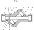
- FIG. 7 is a transverse cross-sectional view of an ultrasonic flowmeter according to an embodiment.
- sensor plate 8 is disposed on the upstream side of opening hole 5 in flow path 2 where the ultrasonic transducer 3 is disposed, and since the other configurations are the same as those in the first example, the description thereof is omitted.
- sensor plate 8 is disposed, on the upstream side of flow path 2, as rectifier 21 that adjusts the flow state of the fluid to be measured, thereby enabling more stable flow rate measurement with reduced turbulence in the flow of the fluid to be measured. Thinner sensor plate 8 can prevent an increase in flow resistance.
- FIG. 8A is a longitudinal sectional view of an ultrasonic flowmeter.
- FIG. 8B is a view illustrating another configuration of the sensor plate of the ultrasonic flowmeter.
- sensor plate 26 integrally with substrate 28 so that a part of substrate 28 projects on a plane
- temperature sensor 11 and pressure sensor 15 of sensor plate 26 can be simultaneously arranged when circuit components constituting a controller on the substrate 28 are disposed, and hence a reduction in man-hours can be achieved.
- sensor plate 27 is configured to project parallel to the plane of substrate 29 by using connector 16 as illustrated in FIG. 8B , the same effect as that of the second example of substrate 29 can be obtained.
- the placement of the pair of ultrasonic transducers has been described as a configuration in which the propagation path of the ultrasonic wave is formed in a so-called Z shape so as to cross the flow only once.
- the present invention is not limited to this, but the pair of ultrasonic transducers may be disposed on the same side of the measurement flow path, and the ultrasonic propagation path may have a V-shape or an I-shape parallel to the flow.
- the ultrasonic flowmeter of the present disclosure can measure the fluid temperature with high accuracy, can achieve a flowmeter with high measurement accuracy, can easily configure the wiring and airtight configuration of the sensor, and can achieve a highly versatile ultrasonic flowmeter with high ease of assembly and maintainability.
Landscapes
- Physics & Mathematics (AREA)
- General Physics & Mathematics (AREA)
- Fluid Mechanics (AREA)
- Electromagnetism (AREA)
- Measuring Volume Flow (AREA)
- Measuring Temperature Or Quantity Of Heat (AREA)
Description
- The present disclosure relates to an ultrasonic flowmeter that propagates ultrasonic waves to a fluid flowing in a measurement flow path to measure the flow velocity of the fluid and adds the temperature measurement of the fluid to enhance measurement accuracy.
- Conventionally, as an ultrasonic flowmeter that measures a flow rate by ultrasonic waves and also measures a temperature of a fluid, there is known an ultrasonic flowmeter that inserts a cylindrical thermistor into a flow path to measure a temperature (e.g., see Patent Literature (PTL) 1).
-
FIG. 9 illustrates a cross-section of an ultrasonic flowmeter described inPTL 1. - In this flowmeter, a pair of
ultrasonic transducers flow path body 103,deflection mirrors ultrasonic transducers measurement flow path 106 to measure a flow velocity and a flow rate. Further,cylindrical thermistor 108 is inserted from the wall surface offlow path body 103 so as to be positioned at the flow center on the downstream side offlow path 107, andmount 109 ofthermistor 108 is hermetically sealed with O-ring 110 or the like to measure the temperature of the fluid. - PTL 1: Unexamined
Japanese Patent Publication (Translation of PCT Application) No. 2004-526127 -
US 2015/082913 A1 relates to an ultrasonic flow meter for detecting the flow rate of a liquid based on a propagation velocity difference exhibited when acoustic waves are propagated through the liquid. -
EP 2 749 855 A2 - However, in the conventional configuration, the cylindrical portion of
thermistor 108 is formed of a metal pipe or the like, and a temperature detector is disposed at its tip, whereby the temperature of the outer wall surface offlow path body 103 has an influence due to the heat transfer action of the metallic cylindrical portion. In particular, when the difference between the ambient temperature on the outer wall surface offlow path body 103 and the fluid temperature is large, an error occurs in temperature measurement, which has been problematic. - Further, as in the conventional configuration illustrated in
FIG. 9 , by reducing the diameter of the cylindrical portion, the influence from the wall surface can be reduced when the heat transfer from the fluid is high, such as when the flow velocity is high, but when the heat transfer is not large, such as when the fluid to be measured is a gas or when the flow velocity is low, there is a possibility that a temperature measurement error may occur due to the influence of the wall surface temperature offlow path body 103. - The present disclosure provides an ultrasonic flowmeter that significantly reduces the influence of ambient temperature to measure fluid temperature with high accuracy and enhances the accuracy of flow rate measurement.
- An ultrasonic flowmeter of the present disclosure according to appended
patent claim 1 includes: a flow path body having a flow path through which a fluid to be measured flows; a pair of ultrasonic transducers disposed in the flow path body; a substrate fixed to the flow path body; and a sensor plate on which a temperature sensor for detecting a temperature of the fluid to be measured is disposed, the sensor plate being flat. The ultrasonic flowmeter also includes an arithmetic unit that calculates a flow rate of the fluid to be measured from a propagation time of ultrasonic waves between the pair of ultrasonic transducers and the temperature detected by the temperature sensor. The sensor plate is configured to project from the substrate and to project into a flow path cross-section of the flow path from a sensor hole provided in the flow path body at a time of fixing the substrate to the flow path body. The sensor plate is a rectifier that is disposed on an upstream side of the flow path to regulate a flow of the fluid to be measured. - With this configuration, it is possible to achieve an ultrasonic flowmeter that can significantly reduce the influence of the ambient temperature of the flow path to measure the fluid temperature with high accuracy and has high measurement accuracy.
- The ultrasonic flowmeter of the present disclosure includes a flat sensor plate provided with a temperature sensor projected and fixed to the substrate, and the sensor plate has the temperature sensor disposed to project in a flow cross-section along the flow direction of the flow path, whereby it is possible to achieve a flowmeter that can significantly reduce the influence of the ambient temperature of the flow path to measure the fluid temperature with high accuracy and has high versatility and high measurement accuracy.
-
-
FIG. 1 is a transverse cross-sectional view of an ultrasonic flowmeter. -
FIG. 2 is a cross-sectional view taken along line 2-2 inFIG. 1 . -
FIG. 3 is a view on arrow A ofFIG. 2 illustrating a sensor plate of the ultrasonic flowmeter ofFIG. 1 . -
FIG. 4 is a perspective view of a substrate and the sensor plate of the ultrasonic flowmeter ofFIG. 1 . -
FIG. 5 is a partial perspective view illustrating a configuration of a sensor plate of an ultrasonic flowmeter. -
FIG. 6 is a partial perspective view illustrating another configuration of the sensor plate of the ultrasonic flowmeter ofFIG. 5 . -
FIG. 7 is a transverse cross-sectional view of an ultrasonic flowmeter according to an embodiment. -
FIG. 8A is a longitudinal sectional view of an ultrasonic flowmeter. -
FIG. 8B is a view illustrating another configuration of the sensor plate of the ultrasonic flowmeter ofFIG. 8A . -
FIG. 9 is a cross-sectional view illustrating a configuration of a flow path in a conventional ultrasonic flowmeter. - Examples and embodiments will be described below with reference to the drawings. The present disclosure is not limited by the exemplary embodiments, but solely defined by the appended patent claims.
- A first example will be described with reference to
FIGS. 1 to 4 . - As illustrated in
FIGS. 1 to 4 , a pair ofultrasonic transducers flow path body 1 so as to face each other at a predetermined angle θ in the flow axis direction offlow path 2 through which a fluid to be measured (a gas such as air, methane, nitrogen, or hydrogen, or a liquid such as water or kerosene) flows.Ultrasonic transducers opening hole 5 opened inflow path 2 by vibration-proof sealing body 6 and fixedbody 7 and are installed airtightly so that the fluid to be measured does not leak fromopening hole 5. - Further,
sensor hole 10 is formed on the downstream side ofopening hole 5 in whichultrasonic transducer 4 is arranged inflow path 2, andflat sensor plate 8, which is mounted withtemperature sensor 11 configured to measure the temperature of the fluid to be measured, projects fromsensor hole 10 intoflow path 2.Sensor plate 8 is fixed tosubstrate 9 so as to project fromsubstrate 9 and is disposed so thatsensor plate 8 is inserted intosensor hole 10 offlow path body 1 andtemperature sensor 11 is positioned at a substantially central portion in the rectangular cross-section offlow path 2.Sealing body 12 such as an O-ring is interposed betweenflow path 2 andsubstrate 9, to whichsensor plate 8 is fixed, for hermetical holding to prevent the fluid to be measured from leaking to the outside offlow path body 1. -
Flow path 2 is connected to an external pipe (not illustrated) viainlet connection 13 andoutlet connection 14 to allow the flow of the fluid to be measured. - Here, as illustrated in
FIG. 4 ,sensor plate 8 is shaped like a thin strip having thickness T extremely smaller than width W and height H, and as illustrated inFIGS. 3 and4 , the direction of width W ofsensor plate 8 is set to a direction along flow direction F inflow path 2 to make it difficult to receive the flow resistance of the flow of the fluid to be measured. The surface ofsensor plate 8 provided withtemperature sensor 11 is coated to enhance the corrosion resistance to the fluid to be measured. -
Sensor plate 8 is not a rigid substrate with large hardness but is formed of a film-shaped flexible substrate and hasflexible portion 18 that can be bent, so that thickness T can be made thinner to reduce the flow resistance of the fluid to be measured. In addition, evensensor plate 8 is erroneously brought into contact during production or maintenance,sensor plate 8 can be prevented from being broken by being bent and releasing the force. - Further,
sensor plate 8 is provided withpressure sensor 15 for correcting a flow rate measurement value by fluid pressure, and as illustrated inFIG. 2 ,pressure sensor 15 is provided so as to be positioned insensor hole 10 without being directly exposed to the main flow inflow path 2, thereby making it difficult to receive the flow resistance of the fluid to be measured. - As illustrated in
FIGS. 1 and 2 , in order to reliably holdsensor plate 8, groove-shaped guide 19 is provided on the wall surface offlow path 2 in sensor hole 10 (shown by partially broken inFIG. 2 ).Guide 19 fits and supportssensor plate 8 insensor hole 10. Further,tip 8a ofsensor plate 8 is inserted into and brought into contact withtip guide groove 20 formed by being recessed in the wall surface offlow path 2, andtip guide groove 20 holdstip 8a of thesensor plate 8. In this way,guide 19 supportssensor plate 8 insensor hole 10, andtip guide groove 20 holdstip 8a ofsensor plate 8, thereby preventing vibration ofsensor plate 8 due to the flow of the fluid to be measured and preventingsensor plate 8 attached toconnector 16 from falling off fromsubstrate 9. - In the present example, the case has been shown where the pressure is detected as a fluid characteristic value in addition to the temperature by disposing
pressure sensor 15 onsensor plate 8. However, by mounting sensors for concentration, humidity, and the like and a detection sensor for a gas such as CO onsensor plate 8, it is possible to measure a characteristic corresponding to each of the sensors, and it is possible to enhance the measurement function of the fluid characteristic. - By forming
sensor plate 8 with a flexible substrate, a wiring portion can be provided in the plastic film, and the surface coating treatment for imparting corrosion resistance can be made unnecessary to achieve cost reduction and simplification. - Further, as illustrated in
FIG. 4 ,substrate 9 is configured such thatsensor unit 9a havingsensor plate 8 disposed thereon andcontroller 9b including a circuit for transmission and reception of ultrasonic waves and a flow rate measurement control circuit are integrated with each other, andsensor plate 8 andcontrol unit 9b do not need to be connected by a lead wire.Substrate 9 is shielded by being covered withmetal case 30 illustrated inFIG. 2 . - Next, the operation of the ultrasonic flowmeter according to the present example will be described.
- One
ultrasonic transducer flow path 2, and the otherultrasonic transducer - A microcomputer unit including a transmission and reception circuit for transmitting and receiving ultrasonic waves by using
ultrasonic transducers controller 9b, andcontroller 9b is connected toultrasonic transducers lead wire 22. Further,sensor unit 9a provided withsensor plate 8 andcontroller 9b having the microcomputer unit are integrated, andsensor unit 9a andcontroller 9b are connected by printed wiring insubstrate 9 to eliminate wiring by lead wires ofcontroller 9b andsensor unit 9a, thereby achieving simplification of the configuration, cost reduction, and improvement in ease of assembly. In addition, by the attachment to flowpath body 1 with sealingbody 12 interposed as illustrated inFIG. 2 , the mounting ofsubstrate 9 and the airtight sealing ofsensor plate 8 can be performed at the same time, so that the ease of assembly can be enhanced. - Further,
connection terminal 23 is provided onsubstrate 9, and a power supply, a measurement instruction, output of a measurement result, and the like are externally supplied tosensor unit 9a andcontroller 9b viaconnection terminal 23. - In measuring the flow rate of the fluid to be measured, it is very important to know the sound velocity of the ultrasonic wave so as to calculate the flow velocity from the propagation time. When the temperature of the fluid to be measured is a known value and is substantially constant, the temperature may be set as a predetermined constant value and the flow rate may be measured. However, since the sound velocity changes greatly depending on the temperature, when the ultrasonic flowmeter is used as a general-purpose flowmeter, it is effective to detect the fluid temperature and increase the measurement accuracy by using the sound velocity value at the fluid temperature. In the present example, since
temperature sensor 11 is provided onsensor plate 8 having a compact and simple configuration, it is possible to achieve a highly versatile and convenient ultrasonic flowmeter having a simple and compact configuration and further improved measurement accuracy. - Furthermore, by adding
pressure sensor 15 tosensor plate 8, a compact sensor unit can be achieved to simplify components and reduce cost, and by using a flow state and a sound velocity in accordance with the pressure of the fluid to be measured for various fluids to be measured having different pressure conditions, measurement accuracy can be further enhanced, whereby a flowmeter with further enhanced measurement accuracy and improved versatility and convenience can be provided. - Since the sound velocity change due to the pressure change is not so large as compared with the magnitude of the sound velocity change due to the temperature change, the necessity of pressure detection is smaller than the necessity of temperature detection. However, by incorporating
pressure sensor 15, the high measurement accuracy can be achieved for applications with different pressures, and the versatility can be further enhanced. In the present example,pressure sensor 15 is housed and disposed insensor hole 10 that hardly receives the flow resistance of the fluid to be measured, it is possible to selectpressure sensor 15 with little consideration of the flow resistance, and it is possible to relax the restriction of the allowable range of the size ofpressure sensor 15 and increase the degree of freedom in selecting a component. - In addition, since
sensor plate 8 is provided with bendable,flexible portion 18 formed of a flexible substrate, even whensensor plate 8 is erroneously brought into contact before assembly at the time of manufacturing, component replacement, or the like,sensor plate 8 can be prevented from being broken due to unexpected contact by being bent and releasing the force atflexible portion 18 and can thus be easily handled, thereby enhancing the ease of assembly. -
Tip 8a ofsensor plate 8 is inserted into and come into contact withtip guide groove 20 provided on the wall surface offlow path 2, the vibration ofsensor plate 8 due to the flow of the fluid to be measured is suppressed to preventsensor plate 8 from being broken, and whenconnector 16 is provided and incorporated,sensor plate 8 can be prevented from coming off and falling off fromconnector 16. - Further, with
sensor plate 8 being fitted to guide 19 provided on the wall surface offlow path 2,sensor plate 8 is pressed byguide 19 to prevent the vibration ofsensor plate 8 due to the flow of the fluid to be measured, thereby preventing the breakage, and a thin flexible substrate can be used assensor plate 8 to simplify the configuration and improve the reliability. -
FIG. 5 is a partial perspective view illustrating a configuration of a sensor plate of an ultrasonic flowmeter according to a second example, and since the other configurations are the same as those of the first example, the description thereof is omitted. - As illustrated in
FIG. 5 ,connector 16 is fixedly disposed onsubstrate 9,sensor plate 24 havingelectrical contact 17 is inserted intoconnector 16, andsensor plate 24 is detachably attached tosubstrate 9 so as to perform signal transmission of a temperature detection signal and a pressure detection signal viaelectrical contact 17. -
FIG. 6 is a perspective view illustrating another configuration ofsensor plate 24 illustrated inFIG. 5 , and as illustrated in the figure,sensor plate 25 is formed of a film-shaped flexible substrate, thickness T1 of the portion where the sensor is disposed is increased, thickness T2 of the other portion is kept thin (T1 > T2), and the sensor plate hasflexible portions sensor plate 25 is improved while breakage is prevented. - According to
sensor plates connector 16 is provided onsubstrate 9 to detachably attachsensor plates substrate 9 side viaelectrical contact 17 to make thesensor plates - Hence the producer side of the flowmeter can improve productivity such as component sharing with respect to expansion of product types, and the user side of the flowmeter can improve the application expansion and the maintainability by the sensor plate replacement with less investment. Therefore, it is possible to achieve an ultrasonic flowmeter with enhanced versatility and good productivity and maintainability.
- With
electrical contact 17 being present inconnector 16, there is a restriction that the ultrasonic flowmeter cannot be used for a conductive liquid such as water as the fluid to be measured, but improvement in productivity and versatility and improvement in maintainability are more effective. -
FIG. 7 is a transverse cross-sectional view of an ultrasonic flowmeter according to an embodiment. In the ultrasonic flowmeter according to the embodiment,sensor plate 8 is disposed on the upstream side ofopening hole 5 inflow path 2 where theultrasonic transducer 3 is disposed, and since the other configurations are the same as those in the first example, the description thereof is omitted. - In the present exemplary embodiment,
sensor plate 8 is disposed, on the upstream side offlow path 2, asrectifier 21 that adjusts the flow state of the fluid to be measured, thereby enabling more stable flow rate measurement with reduced turbulence in the flow of the fluid to be measured.Thinner sensor plate 8 can prevent an increase in flow resistance. -
FIG. 8A is a longitudinal sectional view of an ultrasonic flowmeter.FIG. 8B is a view illustrating another configuration of the sensor plate of the ultrasonic flowmeter. As illustrated inFIG. 8A , by formingsensor plate 26 integrally withsubstrate 28 so that a part ofsubstrate 28 projects on a plane,temperature sensor 11 andpressure sensor 15 ofsensor plate 26 can be simultaneously arranged when circuit components constituting a controller on thesubstrate 28 are disposed, and hence a reduction in man-hours can be achieved. In a case wheresensor plate 27 is configured to project parallel to the plane ofsubstrate 29 by usingconnector 16 as illustrated inFIG. 8B , the same effect as that of the second example ofsubstrate 29 can be obtained. - As described above, in the present example, the placement of the pair of ultrasonic transducers has been described as a configuration in which the propagation path of the ultrasonic wave is formed in a so-called Z shape so as to cross the flow only once. However, the present invention is not limited to this, but the pair of ultrasonic transducers may be disposed on the same side of the measurement flow path, and the ultrasonic propagation path may have a V-shape or an I-shape parallel to the flow.
- Although the example in which the measurement flow path has a rectangular cross-section has been shown here, it is needless to say that the same applies to other circular cross sections.
- As described above, the ultrasonic flowmeter of the present disclosure can measure the fluid temperature with high accuracy, can achieve a flowmeter with high measurement accuracy, can easily configure the wiring and airtight configuration of the sensor, and can achieve a highly versatile ultrasonic flowmeter with high ease of assembly and maintainability.
- By adopting this method, even when the fluid to be measured is changed or even when the measurement purpose is different, it is possible to cope with the change only by replacing the sensor plate, and it is possible to construct a system of an ultrasonic flowmeter having a wide application range and high versatility.
-
- 1
- flow path body
- 2
- flow path
- 3, 4
- ultrasonic transducer
- 8, 24, 25, 26, 27
- sensor plate
- 8a
- tip
- 9, 28, 29
- substrate
- 9a
- sensor unit
- 9b
- controller (arithmetic unit)
- 10
- sensor hole
- 11
- temperature sensor
- 12
- sealing body
- 15
- pressure sensor
- 16
- connector
- 18, 18a, 18b, 18c
- flexible portion
- 19
- guide
- 21
- rectifier
Claims (8)
- An ultrasonic flowmeter comprising:a flow path body (1) having a flow path (2) where a fluid to be measured flows;a pair of ultrasonic transducers (3, 4) disposed in the flow path body (1);a substrate (9, 28, 29) fixed to the flow path body (1);a sensor plate (8) where a temperature sensor (11) for detecting a temperature of the fluid to be measured is disposed, the sensor plate (8) being flat; andan arithmetic unit (9b) that calculates a flow rate of the fluid to be measured from a propagation time of ultrasonic waves between the pair of ultrasonic transducers (3, 4) and the temperature detected by the temperature sensor (11),wherein the sensor plate (8) is configured to project from the substrate (9, 28, 29) and to project into a flow path cross-section of the flow path (2) from a sensor hole (10) provided in the flow path body (1) at a time of fixing the substrate (9, 28, 29) to the flow path body (1),wherein the sensor plate (8) is a rectifier that is disposed on an upstream side of the flow path (2) to regulate a flow of the fluid to be measured.
- The ultrasonic flowmeter according to claim 1, whereinthe sensor plate (8) is fixed to project perpendicularly from the substrate (9, 28, 29), anda sealing body (12) is provided between the substrate (9, 28, 29) and the flow path body (1) to prevent leakage of the fluid to be measured from the sensor
- The ultrasonic flowmeter according to claim 1 or 2, whereinthe substrate (9, 28, 29) has a connector (16) disposed, andthe sensor plate (8) is detachably attached via the connector (16).
- The ultrasonic flowmeter according to any one of claims 1 to 3, wherein the sensor plate (8) is provided with a bendable flexible portion (18, 18a, 18b, 18c) formed of a flexible substrate.
- The ultrasonic flowmeter according to any one of claims 1 to 4, wherein the sensor plate (8) has a tip in contact with a wall surface of the flow path (2).
- The ultrasonic flowmeter according to any one of claims 1 to 5, wherein the sensor plate (8) is fitted to a guide provided on an inner wall surface of the sensor hole (10).
- The ultrasonic flowmeter according to any one of claims 1 to 6, wherein the sensor plate (8) includes a pressure sensor (15) for detecting a pressure that is a fluid characteristic of the fluid to be measured.
- The ultrasonic flowmeter according to any one of claims 1 to 7, wherein the arithmetic unit (9b) is disposed on the substrate (9, 28, 29).
Applications Claiming Priority (2)
| Application Number | Priority Date | Filing Date | Title |
|---|---|---|---|
| JP2019065595A JP7203302B2 (en) | 2019-03-29 | 2019-03-29 | ultrasonic flow meter |
| PCT/JP2020/011115 WO2020203183A1 (en) | 2019-03-29 | 2020-03-13 | Ultrasonic flowmeter |
Publications (3)
| Publication Number | Publication Date |
|---|---|
| EP3951328A1 EP3951328A1 (en) | 2022-02-09 |
| EP3951328A4 EP3951328A4 (en) | 2022-05-18 |
| EP3951328B1 true EP3951328B1 (en) | 2023-06-14 |
Family
ID=72668428
Family Applications (1)
| Application Number | Title | Priority Date | Filing Date |
|---|---|---|---|
| EP20783573.7A Active EP3951328B1 (en) | 2019-03-29 | 2020-03-13 | Ultrasonic flowmeter |
Country Status (5)
| Country | Link |
|---|---|
| US (1) | US12104937B2 (en) |
| EP (1) | EP3951328B1 (en) |
| JP (1) | JP7203302B2 (en) |
| CN (1) | CN113383212B (en) |
| WO (1) | WO2020203183A1 (en) |
Families Citing this family (3)
| Publication number | Priority date | Publication date | Assignee | Title |
|---|---|---|---|---|
| JP2021089190A (en) * | 2019-12-03 | 2021-06-10 | 株式会社デンソー | Flow rate detector |
| US12422312B2 (en) * | 2021-11-12 | 2025-09-23 | United States Of America, As Represented By The Secretary Of The Navy | Spinning flat plate calorimeter |
| KR20250106113A (en) * | 2024-01-02 | 2025-07-09 | 하이텍앤솔 주식회사 | Ultrasonic water meter flow measurement and outdoor water leak detection method using temperature distribution and pressure change, and thereof the ultrasonic water meter |
Family Cites Families (21)
| Publication number | Priority date | Publication date | Assignee | Title |
|---|---|---|---|---|
| JPH07225158A (en) * | 1994-02-15 | 1995-08-22 | Nippondenso Co Ltd | Temperature sensor and its mounting method |
| DE4415889A1 (en) * | 1994-05-05 | 1995-11-16 | Hydrometer Gmbh | Transducer for measuring liquid flows with ultrasound |
| JPH08240460A (en) * | 1995-03-07 | 1996-09-17 | Tokyo Gas Co Ltd | Flowmeter and manufacturing method thereof |
| JP3719802B2 (en) * | 1996-12-27 | 2005-11-24 | 東京瓦斯株式会社 | Multipoint flow meter |
| JP2000046608A (en) * | 1998-07-29 | 2000-02-18 | Mitsui Mining & Smelting Co Ltd | Flow sensor |
| DE10047383C1 (en) | 2000-09-25 | 2001-11-08 | Siemens Ag | Ultrasonic flowmeter has relatively spaced ultrasonic heads each provided with associated reflector for ultrasonic waves |
| WO2004094960A2 (en) * | 2003-04-21 | 2004-11-04 | Teijin Pharma Limited | Ultrasonic apparatus and method for measuring the concentration and flow rate of gas |
| JP4207662B2 (en) * | 2003-05-20 | 2009-01-14 | 日産自動車株式会社 | Ultrasonic fluid sensor |
| JP5293278B2 (en) * | 2009-03-05 | 2013-09-18 | 株式会社デンソー | Thermal flow meter |
| US20120191382A1 (en) * | 2009-10-01 | 2012-07-26 | Panasonic Corporation | Ultrasonic flow meter device |
| JP5682156B2 (en) * | 2010-06-24 | 2015-03-11 | パナソニックIpマネジメント株式会社 | Ultrasonic flow meter |
| JP2012242298A (en) * | 2011-05-20 | 2012-12-10 | Denso Corp | Flow rate detection device |
| JP5934622B2 (en) * | 2012-09-25 | 2016-06-15 | 愛知時計電機株式会社 | Temperature measuring instrument, flow meter and temperature measuring method |
| US9709461B2 (en) * | 2012-11-30 | 2017-07-18 | Sensata Technologies, Inc. | Method of integrating a temperature sensing element |
| JP2015017857A (en) * | 2013-07-10 | 2015-01-29 | 株式会社デンソー | Flow sensor |
| JP5984094B2 (en) | 2013-09-24 | 2016-09-06 | Smc株式会社 | Ultrasonic flow meter |
| US9372106B2 (en) * | 2014-01-14 | 2016-06-21 | General Electric Company | Non-circular flowmeter |
| CN114796782A (en) | 2015-12-02 | 2022-07-29 | 费雪派克医疗保健有限公司 | Flow path sensing for flow therapy devices |
| CN205861143U (en) * | 2016-07-28 | 2017-01-04 | 重庆前卫克罗姆表业有限责任公司 | A kind of integrated form runner for gas meter, flow meter or effusion meter |
| CN108168630B (en) * | 2016-12-07 | 2019-11-01 | 辽宁思凯科技股份有限公司 | A kind of ultrasonic water meter detection device and measuring method |
| JP6838807B2 (en) * | 2017-03-31 | 2021-03-03 | 日立Astemo株式会社 | Ultrasonic gas sensor device |
-
2019
- 2019-03-29 JP JP2019065595A patent/JP7203302B2/en active Active
-
2020
- 2020-03-13 CN CN202080012719.0A patent/CN113383212B/en active Active
- 2020-03-13 US US17/425,931 patent/US12104937B2/en active Active
- 2020-03-13 WO PCT/JP2020/011115 patent/WO2020203183A1/en not_active Ceased
- 2020-03-13 EP EP20783573.7A patent/EP3951328B1/en active Active
Also Published As
| Publication number | Publication date |
|---|---|
| WO2020203183A1 (en) | 2020-10-08 |
| CN113383212A (en) | 2021-09-10 |
| JP7203302B2 (en) | 2023-01-13 |
| US12104937B2 (en) | 2024-10-01 |
| JP2020165760A (en) | 2020-10-08 |
| EP3951328A4 (en) | 2022-05-18 |
| US20220170770A1 (en) | 2022-06-02 |
| CN113383212B (en) | 2024-07-09 |
| EP3951328A1 (en) | 2022-02-09 |
Similar Documents
| Publication | Publication Date | Title |
|---|---|---|
| US12104937B2 (en) | Ultrasonic flowmeter | |
| EP2639560B1 (en) | Ultrasonic flow rate measurement device | |
| US7607359B2 (en) | Ultrasonic flow rate meter having a pressure sensor | |
| JP5728657B2 (en) | Ultrasonic flow measurement unit | |
| JP7681831B2 (en) | Hydrogen flow concentration meter | |
| EP1719981A1 (en) | Fluid sensor of anticorrosive metal and fluid supply device using same | |
| EP3488192B1 (en) | Vortex flowmeter with reduced process intrusion | |
| US20120191382A1 (en) | Ultrasonic flow meter device | |
| EP3104134A1 (en) | Gas flowmeter | |
| JP4415662B2 (en) | Ultrasonic flow meter | |
| JP5240763B2 (en) | Ultrasonic flow meter | |
| JP7702178B2 (en) | Ultrasonic flow measurement device for rectangular pipes | |
| US20240125634A1 (en) | Ultrasonic flowmeter | |
| JP2020139889A (en) | Measuring device | |
| JP6313048B2 (en) | Measuring unit and flow rate measuring apparatus including the same | |
| EP3851811B1 (en) | Ultrasonic flowmeter | |
| JP7373771B2 (en) | Physical quantity measuring device | |
| US20250314511A1 (en) | Integrated enclosure for ultrasonic flowmeter | |
| JP4037221B2 (en) | In-pipe flow measurement device | |
| JP4976187B2 (en) | Flowmeter | |
| JP2025122760A (en) | ultrasonic flow meter | |
| WO2024171884A1 (en) | Hydrogen flow rate/concentration meter | |
| JP2020139890A (en) | Measuring device | |
| JPH02268230A (en) | Pressure sensor and gas flowmeter using it |
Legal Events
| Date | Code | Title | Description |
|---|---|---|---|
| STAA | Information on the status of an ep patent application or granted ep patent |
Free format text: STATUS: THE INTERNATIONAL PUBLICATION HAS BEEN MADE |
|
| PUAI | Public reference made under article 153(3) epc to a published international application that has entered the european phase |
Free format text: ORIGINAL CODE: 0009012 |
|
| STAA | Information on the status of an ep patent application or granted ep patent |
Free format text: STATUS: REQUEST FOR EXAMINATION WAS MADE |
|
| 17P | Request for examination filed |
Effective date: 20210810 |
|
| AK | Designated contracting states |
Kind code of ref document: A1 Designated state(s): AL AT BE BG CH CY CZ DE DK EE ES FI FR GB GR HR HU IE IS IT LI LT LU LV MC MK MT NL NO PL PT RO RS SE SI SK SM TR |
|
| RIC1 | Information provided on ipc code assigned before grant |
Ipc: G01F 15/18 20060101ALN20220404BHEP Ipc: G01K 13/02 20210101ALI20220404BHEP Ipc: G01F 15/02 20060101ALI20220404BHEP Ipc: G01F 1/667 20220101ALI20220404BHEP Ipc: G01F 1/66 20220101AFI20220404BHEP |
|
| A4 | Supplementary search report drawn up and despatched |
Effective date: 20220414 |
|
| RIC1 | Information provided on ipc code assigned before grant |
Ipc: G01F 15/18 20060101ALN20220408BHEP Ipc: G01K 13/02 20210101ALI20220408BHEP Ipc: G01F 15/02 20060101ALI20220408BHEP Ipc: G01F 1/667 20220101ALI20220408BHEP Ipc: G01F 1/66 20220101AFI20220408BHEP |
|
| DAV | Request for validation of the european patent (deleted) | ||
| DAX | Request for extension of the european patent (deleted) | ||
| GRAP | Despatch of communication of intention to grant a patent |
Free format text: ORIGINAL CODE: EPIDOSNIGR1 |
|
| STAA | Information on the status of an ep patent application or granted ep patent |
Free format text: STATUS: GRANT OF PATENT IS INTENDED |
|
| RIC1 | Information provided on ipc code assigned before grant |
Ipc: G01F 15/18 20060101ALN20221207BHEP Ipc: G01K 13/02 20210101ALI20221207BHEP Ipc: G01F 15/02 20060101ALI20221207BHEP Ipc: G01F 1/667 20220101ALI20221207BHEP Ipc: G01F 1/66 20220101AFI20221207BHEP |
|
| RIC1 | Information provided on ipc code assigned before grant |
Ipc: G01F 15/18 20060101ALN20221212BHEP Ipc: G01K 13/02 20210101ALI20221212BHEP Ipc: G01F 15/02 20060101ALI20221212BHEP Ipc: G01F 15/00 20060101ALI20221212BHEP Ipc: G01F 1/667 20220101ALI20221212BHEP Ipc: G01F 1/66 20220101AFI20221212BHEP |
|
| INTG | Intention to grant announced |
Effective date: 20230109 |
|
| GRAS | Grant fee paid |
Free format text: ORIGINAL CODE: EPIDOSNIGR3 |
|
| GRAA | (expected) grant |
Free format text: ORIGINAL CODE: 0009210 |
|
| STAA | Information on the status of an ep patent application or granted ep patent |
Free format text: STATUS: THE PATENT HAS BEEN GRANTED |
|
| AK | Designated contracting states |
Kind code of ref document: B1 Designated state(s): AL AT BE BG CH CY CZ DE DK EE ES FI FR GB GR HR HU IE IS IT LI LT LU LV MC MK MT NL NO PL PT RO RS SE SI SK SM TR |
|
| REG | Reference to a national code |
Ref country code: CH Ref legal event code: EP |
|
| REG | Reference to a national code |
Ref country code: DE Ref legal event code: R096 Ref document number: 602020012581 Country of ref document: DE |
|
| REG | Reference to a national code |
Ref country code: AT Ref legal event code: REF Ref document number: 1579538 Country of ref document: AT Kind code of ref document: T Effective date: 20230715 |
|
| REG | Reference to a national code |
Ref country code: LT Ref legal event code: MG9D |
|
| REG | Reference to a national code |
Ref country code: NL Ref legal event code: MP Effective date: 20230614 |
|
| PG25 | Lapsed in a contracting state [announced via postgrant information from national office to epo] |
Ref country code: SE Free format text: LAPSE BECAUSE OF FAILURE TO SUBMIT A TRANSLATION OF THE DESCRIPTION OR TO PAY THE FEE WITHIN THE PRESCRIBED TIME-LIMIT Effective date: 20230614 Ref country code: NO Free format text: LAPSE BECAUSE OF FAILURE TO SUBMIT A TRANSLATION OF THE DESCRIPTION OR TO PAY THE FEE WITHIN THE PRESCRIBED TIME-LIMIT Effective date: 20230914 Ref country code: ES Free format text: LAPSE BECAUSE OF FAILURE TO SUBMIT A TRANSLATION OF THE DESCRIPTION OR TO PAY THE FEE WITHIN THE PRESCRIBED TIME-LIMIT Effective date: 20230614 |
|
| REG | Reference to a national code |
Ref country code: AT Ref legal event code: MK05 Ref document number: 1579538 Country of ref document: AT Kind code of ref document: T Effective date: 20230614 |
|
| PG25 | Lapsed in a contracting state [announced via postgrant information from national office to epo] |
Ref country code: RS Free format text: LAPSE BECAUSE OF FAILURE TO SUBMIT A TRANSLATION OF THE DESCRIPTION OR TO PAY THE FEE WITHIN THE PRESCRIBED TIME-LIMIT Effective date: 20230614 Ref country code: NL Free format text: LAPSE BECAUSE OF FAILURE TO SUBMIT A TRANSLATION OF THE DESCRIPTION OR TO PAY THE FEE WITHIN THE PRESCRIBED TIME-LIMIT Effective date: 20230614 Ref country code: LV Free format text: LAPSE BECAUSE OF FAILURE TO SUBMIT A TRANSLATION OF THE DESCRIPTION OR TO PAY THE FEE WITHIN THE PRESCRIBED TIME-LIMIT Effective date: 20230614 Ref country code: LT Free format text: LAPSE BECAUSE OF FAILURE TO SUBMIT A TRANSLATION OF THE DESCRIPTION OR TO PAY THE FEE WITHIN THE PRESCRIBED TIME-LIMIT Effective date: 20230614 Ref country code: HR Free format text: LAPSE BECAUSE OF FAILURE TO SUBMIT A TRANSLATION OF THE DESCRIPTION OR TO PAY THE FEE WITHIN THE PRESCRIBED TIME-LIMIT Effective date: 20230614 Ref country code: GR Free format text: LAPSE BECAUSE OF FAILURE TO SUBMIT A TRANSLATION OF THE DESCRIPTION OR TO PAY THE FEE WITHIN THE PRESCRIBED TIME-LIMIT Effective date: 20230915 |
|
| PG25 | Lapsed in a contracting state [announced via postgrant information from national office to epo] |
Ref country code: FI Free format text: LAPSE BECAUSE OF FAILURE TO SUBMIT A TRANSLATION OF THE DESCRIPTION OR TO PAY THE FEE WITHIN THE PRESCRIBED TIME-LIMIT Effective date: 20230614 |
|
| PG25 | Lapsed in a contracting state [announced via postgrant information from national office to epo] |
Ref country code: SK Free format text: LAPSE BECAUSE OF FAILURE TO SUBMIT A TRANSLATION OF THE DESCRIPTION OR TO PAY THE FEE WITHIN THE PRESCRIBED TIME-LIMIT Effective date: 20230614 |
|
| PG25 | Lapsed in a contracting state [announced via postgrant information from national office to epo] |
Ref country code: IS Free format text: LAPSE BECAUSE OF FAILURE TO SUBMIT A TRANSLATION OF THE DESCRIPTION OR TO PAY THE FEE WITHIN THE PRESCRIBED TIME-LIMIT Effective date: 20231014 |
|
| PG25 | Lapsed in a contracting state [announced via postgrant information from national office to epo] |
Ref country code: SM Free format text: LAPSE BECAUSE OF FAILURE TO SUBMIT A TRANSLATION OF THE DESCRIPTION OR TO PAY THE FEE WITHIN THE PRESCRIBED TIME-LIMIT Effective date: 20230614 Ref country code: SK Free format text: LAPSE BECAUSE OF FAILURE TO SUBMIT A TRANSLATION OF THE DESCRIPTION OR TO PAY THE FEE WITHIN THE PRESCRIBED TIME-LIMIT Effective date: 20230614 Ref country code: RO Free format text: LAPSE BECAUSE OF FAILURE TO SUBMIT A TRANSLATION OF THE DESCRIPTION OR TO PAY THE FEE WITHIN THE PRESCRIBED TIME-LIMIT Effective date: 20230614 Ref country code: PT Free format text: LAPSE BECAUSE OF FAILURE TO SUBMIT A TRANSLATION OF THE DESCRIPTION OR TO PAY THE FEE WITHIN THE PRESCRIBED TIME-LIMIT Effective date: 20231016 Ref country code: IS Free format text: LAPSE BECAUSE OF FAILURE TO SUBMIT A TRANSLATION OF THE DESCRIPTION OR TO PAY THE FEE WITHIN THE PRESCRIBED TIME-LIMIT Effective date: 20231014 Ref country code: EE Free format text: LAPSE BECAUSE OF FAILURE TO SUBMIT A TRANSLATION OF THE DESCRIPTION OR TO PAY THE FEE WITHIN THE PRESCRIBED TIME-LIMIT Effective date: 20230614 Ref country code: CZ Free format text: LAPSE BECAUSE OF FAILURE TO SUBMIT A TRANSLATION OF THE DESCRIPTION OR TO PAY THE FEE WITHIN THE PRESCRIBED TIME-LIMIT Effective date: 20230614 Ref country code: AT Free format text: LAPSE BECAUSE OF FAILURE TO SUBMIT A TRANSLATION OF THE DESCRIPTION OR TO PAY THE FEE WITHIN THE PRESCRIBED TIME-LIMIT Effective date: 20230614 |
|
| PG25 | Lapsed in a contracting state [announced via postgrant information from national office to epo] |
Ref country code: PL Free format text: LAPSE BECAUSE OF FAILURE TO SUBMIT A TRANSLATION OF THE DESCRIPTION OR TO PAY THE FEE WITHIN THE PRESCRIBED TIME-LIMIT Effective date: 20230614 |
|
| REG | Reference to a national code |
Ref country code: DE Ref legal event code: R097 Ref document number: 602020012581 Country of ref document: DE |
|
| PLBE | No opposition filed within time limit |
Free format text: ORIGINAL CODE: 0009261 |
|
| STAA | Information on the status of an ep patent application or granted ep patent |
Free format text: STATUS: NO OPPOSITION FILED WITHIN TIME LIMIT |
|
| PG25 | Lapsed in a contracting state [announced via postgrant information from national office to epo] |
Ref country code: DK Free format text: LAPSE BECAUSE OF FAILURE TO SUBMIT A TRANSLATION OF THE DESCRIPTION OR TO PAY THE FEE WITHIN THE PRESCRIBED TIME-LIMIT Effective date: 20230614 |
|
| PG25 | Lapsed in a contracting state [announced via postgrant information from national office to epo] |
Ref country code: SI Free format text: LAPSE BECAUSE OF FAILURE TO SUBMIT A TRANSLATION OF THE DESCRIPTION OR TO PAY THE FEE WITHIN THE PRESCRIBED TIME-LIMIT Effective date: 20230614 |
|
| 26N | No opposition filed |
Effective date: 20240315 |
|
| PG25 | Lapsed in a contracting state [announced via postgrant information from national office to epo] |
Ref country code: SI Free format text: LAPSE BECAUSE OF FAILURE TO SUBMIT A TRANSLATION OF THE DESCRIPTION OR TO PAY THE FEE WITHIN THE PRESCRIBED TIME-LIMIT Effective date: 20230614 Ref country code: IT Free format text: LAPSE BECAUSE OF FAILURE TO SUBMIT A TRANSLATION OF THE DESCRIPTION OR TO PAY THE FEE WITHIN THE PRESCRIBED TIME-LIMIT Effective date: 20230614 |
|
| PG25 | Lapsed in a contracting state [announced via postgrant information from national office to epo] |
Ref country code: BG Free format text: LAPSE BECAUSE OF FAILURE TO SUBMIT A TRANSLATION OF THE DESCRIPTION OR TO PAY THE FEE WITHIN THE PRESCRIBED TIME-LIMIT Effective date: 20230614 |
|
| PG25 | Lapsed in a contracting state [announced via postgrant information from national office to epo] |
Ref country code: LU Free format text: LAPSE BECAUSE OF NON-PAYMENT OF DUE FEES Effective date: 20240313 |
|
| PG25 | Lapsed in a contracting state [announced via postgrant information from national office to epo] |
Ref country code: MC Free format text: LAPSE BECAUSE OF FAILURE TO SUBMIT A TRANSLATION OF THE DESCRIPTION OR TO PAY THE FEE WITHIN THE PRESCRIBED TIME-LIMIT Effective date: 20230614 |
|
| PG25 | Lapsed in a contracting state [announced via postgrant information from national office to epo] |
Ref country code: MC Free format text: LAPSE BECAUSE OF FAILURE TO SUBMIT A TRANSLATION OF THE DESCRIPTION OR TO PAY THE FEE WITHIN THE PRESCRIBED TIME-LIMIT Effective date: 20230614 Ref country code: LU Free format text: LAPSE BECAUSE OF NON-PAYMENT OF DUE FEES Effective date: 20240313 Ref country code: BG Free format text: LAPSE BECAUSE OF FAILURE TO SUBMIT A TRANSLATION OF THE DESCRIPTION OR TO PAY THE FEE WITHIN THE PRESCRIBED TIME-LIMIT Effective date: 20230614 |
|
| REG | Reference to a national code |
Ref country code: BE Ref legal event code: MM Effective date: 20240331 |
|
| PG25 | Lapsed in a contracting state [announced via postgrant information from national office to epo] |
Ref country code: BE Free format text: LAPSE BECAUSE OF NON-PAYMENT OF DUE FEES Effective date: 20240331 |
|
| PG25 | Lapsed in a contracting state [announced via postgrant information from national office to epo] |
Ref country code: FR Free format text: LAPSE BECAUSE OF NON-PAYMENT OF DUE FEES Effective date: 20240331 |
|
| PG25 | Lapsed in a contracting state [announced via postgrant information from national office to epo] |
Ref country code: IE Free format text: LAPSE BECAUSE OF NON-PAYMENT OF DUE FEES Effective date: 20240313 |
|
| PG25 | Lapsed in a contracting state [announced via postgrant information from national office to epo] |
Ref country code: IE Free format text: LAPSE BECAUSE OF NON-PAYMENT OF DUE FEES Effective date: 20240313 Ref country code: FR Free format text: LAPSE BECAUSE OF NON-PAYMENT OF DUE FEES Effective date: 20240331 Ref country code: BE Free format text: LAPSE BECAUSE OF NON-PAYMENT OF DUE FEES Effective date: 20240331 |
|
| PGFP | Annual fee paid to national office [announced via postgrant information from national office to epo] |
Ref country code: DE Payment date: 20250319 Year of fee payment: 6 |
|
| PGFP | Annual fee paid to national office [announced via postgrant information from national office to epo] |
Ref country code: CH Payment date: 20250401 Year of fee payment: 6 |
|
| PG25 | Lapsed in a contracting state [announced via postgrant information from national office to epo] |
Ref country code: CY Free format text: LAPSE BECAUSE OF FAILURE TO SUBMIT A TRANSLATION OF THE DESCRIPTION OR TO PAY THE FEE WITHIN THE PRESCRIBED TIME-LIMIT; INVALID AB INITIO Effective date: 20200313 |
|
| PG25 | Lapsed in a contracting state [announced via postgrant information from national office to epo] |
Ref country code: HU Free format text: LAPSE BECAUSE OF FAILURE TO SUBMIT A TRANSLATION OF THE DESCRIPTION OR TO PAY THE FEE WITHIN THE PRESCRIBED TIME-LIMIT; INVALID AB INITIO Effective date: 20200313 |
|
| PG25 | Lapsed in a contracting state [announced via postgrant information from national office to epo] |
Ref country code: TR Free format text: LAPSE BECAUSE OF FAILURE TO SUBMIT A TRANSLATION OF THE DESCRIPTION OR TO PAY THE FEE WITHIN THE PRESCRIBED TIME-LIMIT Effective date: 20230614 |
|
| REG | Reference to a national code |
Ref country code: DE Ref legal event code: R084 Ref document number: 602020012581 Country of ref document: DE |
|
| REG | Reference to a national code |
Ref country code: CH Ref legal event code: U11 Free format text: ST27 STATUS EVENT CODE: U-0-0-U10-U11 (AS PROVIDED BY THE NATIONAL OFFICE) Effective date: 20260401 |
|
| PGFP | Annual fee paid to national office [announced via postgrant information from national office to epo] |
Ref country code: GB Payment date: 20260324 Year of fee payment: 7 |
|
| REG | Reference to a national code |
Ref country code: GB Ref legal event code: 746 Effective date: 20260320 |