EP3951310A1 - Optoelektronischer sensor, insbesondere triangulations-lichttaster - Google Patents
Optoelektronischer sensor, insbesondere triangulations-lichttaster Download PDFInfo
- Publication number
- EP3951310A1 EP3951310A1 EP21184947.6A EP21184947A EP3951310A1 EP 3951310 A1 EP3951310 A1 EP 3951310A1 EP 21184947 A EP21184947 A EP 21184947A EP 3951310 A1 EP3951310 A1 EP 3951310A1
- Authority
- EP
- European Patent Office
- Prior art keywords
- thread
- adjustment
- threads
- pitch
- sensor according
- Prior art date
- Legal status (The legal status is an assumption and is not a legal conclusion. Google has not performed a legal analysis and makes no representation as to the accuracy of the status listed.)
- Granted
Links
Images



Classifications
-
- G—PHYSICS
- G01—MEASURING; TESTING
- G01B—MEASURING LENGTH, THICKNESS OR SIMILAR LINEAR DIMENSIONS; MEASURING ANGLES; MEASURING AREAS; MEASURING IRREGULARITIES OF SURFACES OR CONTOURS
- G01B5/00—Measuring arrangements characterised by the use of mechanical techniques
- G01B5/0002—Arrangements for supporting, fixing or guiding the measuring instrument or the object to be measured
- G01B5/0004—Supports
-
- G—PHYSICS
- G01—MEASURING; TESTING
- G01B—MEASURING LENGTH, THICKNESS OR SIMILAR LINEAR DIMENSIONS; MEASURING ANGLES; MEASURING AREAS; MEASURING IRREGULARITIES OF SURFACES OR CONTOURS
- G01B11/00—Measuring arrangements characterised by the use of optical techniques
- G01B11/02—Measuring arrangements characterised by the use of optical techniques for measuring length, width or thickness
- G01B11/026—Measuring arrangements characterised by the use of optical techniques for measuring length, width or thickness by measuring distance between sensor and object
-
- G—PHYSICS
- G01—MEASURING; TESTING
- G01S—RADIO DIRECTION-FINDING; RADIO NAVIGATION; DETERMINING DISTANCE OR VELOCITY BY USE OF RADIO WAVES; LOCATING OR PRESENCE-DETECTING BY USE OF THE REFLECTION OR RERADIATION OF RADIO WAVES; ANALOGOUS ARRANGEMENTS USING OTHER WAVES
- G01S17/00—Systems using the reflection or reradiation of electromagnetic waves other than radio waves, e.g. lidar systems
- G01S17/02—Systems using the reflection of electromagnetic waves other than radio waves
- G01S17/06—Systems determining position data of a target
- G01S17/46—Indirect determination of position data
- G01S17/48—Active triangulation systems, i.e. using the transmission and reflection of electromagnetic waves other than radio waves
-
- G—PHYSICS
- G01—MEASURING; TESTING
- G01S—RADIO DIRECTION-FINDING; RADIO NAVIGATION; DETERMINING DISTANCE OR VELOCITY BY USE OF RADIO WAVES; LOCATING OR PRESENCE-DETECTING BY USE OF THE REFLECTION OR RERADIATION OF RADIO WAVES; ANALOGOUS ARRANGEMENTS USING OTHER WAVES
- G01S7/00—Details of systems according to groups G01S13/00, G01S15/00, G01S17/00
- G01S7/48—Details of systems according to groups G01S13/00, G01S15/00, G01S17/00 of systems according to group G01S17/00
- G01S7/481—Constructional features, e.g. arrangements of optical elements
- G01S7/4811—Constructional features, e.g. arrangements of optical elements common to transmitter and receiver
- G01S7/4813—Housing arrangements
-
- G—PHYSICS
- G01—MEASURING; TESTING
- G01V—GEOPHYSICS; GRAVITATIONAL MEASUREMENTS; DETECTING MASSES OR OBJECTS; TAGS
- G01V8/00—Prospecting or detecting by optical means
- G01V8/10—Detecting, e.g. by using light barriers
- G01V8/12—Detecting, e.g. by using light barriers using one transmitter and one receiver
Definitions
- the invention relates to an optoelectronic sensor with an opto-mechanical arrangement for emitting, receiving or deflecting light beams with an adjustment mechanism for adjusting the optical arrangement, the adjustment mechanism having a first adjustment element which interacts with a second adjustment element, with rotation of the first adjustment element relative displacement of the two adjustment elements to one another.
- Photoelectric sensors with an opto-mechanical arrangement that has to be adjusted are, for example, triangulation light sensors.
- a switching distance usually has to be set and adjusted, which can be done, among other things, by adjusting the receiving lens. If the switching distance is close to the triangulation light scanner, the adjustment path for the receiving lens is greater than if the switching distance is far away. Setting options (coarse or fine) of different sensitivity are therefore required for one and the same opto-mechanical arrangement (receiving lens). This is very difficult to do.
- an adjusting mechanism for adjusting an optical component, in which an adjusting element has an external and an internal thread with different thread pitches.
- the external thread is screwed into a holder.
- the element that is actually to be moved is screwed into the internal thread.
- the element to be moved can be adjusted, the total adjustment path being the sum of the adjustment paths through the two threads.
- An optoelectronic sensor has an opto-mechanical arrangement for emitting, receiving or deflecting light beams, and an adjustment mechanism for adjusting the opto-mechanical arrangement, the adjustment mechanism having a first adjustment element which interacts with a second adjustment element, with turning the first adjustment element relative displacement of the two adjustment elements to each other and thus an adjustment of the opto-mechanical arrangement takes place.
- the first adjustment element has a first thread with a first pitch and a second thread with a different pitch, the second thread lying on the same axis as the first thread, so that the first adjustment element is designed in the manner of a threaded rod with different threads and first and second thread on the axis in the direction of displacement in a row.
- the second adjusting element has a driver which engages in the thread with a larger pitch for coarse adjustment of the opto-mechanical arrangement and engages in the thread with a smaller pitch for fine adjustment.
- the first adjusting element has two threads on the same axis, there is a simple and particularly easy-to-use arrangement to provide both a coarse adjustment (via the thread with a larger pitch) and a fine adjustment (via the thread with a smaller pitch). Coarse and fine adjustments are made by rotating one and the same first adjustment element.
- the driver is preferably in engagement with one of the threads over the entire adjustment path of the adjustment mechanism. This ensures that the two Adjusting each other take a defined position, so that the adjustment are positioned with as little play.
- the transition from coarse to fine adjustment is particularly critical. This should be done in such a way that the element to be adjusted is not adjusted abruptly, but instead performs a continuous, monotonous movement during the adjustment. In a further development of the invention, this is ensured in that the driver only engages in a single thread pitch of the first or second thread, with the two threads with the different pitches merging seamlessly into one another.
- the pitch of the first thread also changes continuously, ie steadily and monotonically, into the pitch of the second thread.
- the thread can be formed from a real spiral worm with a continuously changing pitch, i.e. "infinitely many" different threads. This is advantageous in order to linearize the range setting of the sensor, i.e. to obtain proportionality between the set range and the rotation of the control element.
- the driver not only engages in a thread, but also has a first internal thread with the first pitch to accommodate the first thread designed as an external thread and a second internal thread with the second pitch to accommodate the second thread as an external thread executed thread, wherein the second internal thread is on the same axis as the first.
- the first threads then advantageously have a smaller diameter than the second threads.
- a further development of this embodiment provides that the driver has two opposing jaws, each jaw having part of the first and part of the second internal thread, so that the first Adjusting between the jaws can engage with its external threads. During the transition from coarse to fine adjustment, the jaws then have the opportunity to give in a little.
- the first adjustment element can advantageously be operated by hand.
- the first adjusting element can be operated via a geared down gear.
- An operation via a gear has the advantage that a mechanical decoupling is thereby provided, so that pressure exerted axially by the operation does not act on the adjustment element and the pressure can therefore not cause any unwanted adjustment.
- a possible axial restoring force from the first adjusting element does not act back on the rotary knob, which is advantageous because this is usually sealed with an O-ring on a housing, a reaction could impair the sealing effect.
- Another benefit is that the gear reduction allows for a coarser thread design with deeper engagement for the driver, resulting in a more robust design to vibration and mechanical shock.
- the first adjustment element is arranged in an axially stationary manner in a sensor housing and the opto-mechanical arrangement is coupled to the second adjustment element, which is mounted so as to be axially movable in order to bring about an adjustment of the optical arrangement relative to the sensor housing.
- the first adjustment element has a third thread, with the pitch of the third thread being different from that of the first and second threads, there is a further adjustment option with a different pitch in addition to coarse and fine adjustment.
- the invention is preferably used in a triangulation light scanner.
- the opto-mechanical arrangement is then formed by receiving optics.
- the receiving optics can then be adjusted in the desired manner and with the necessary precision, depending on whether the switching distance is far or near.
- the transmitted light beams are directed into the monitored area and the light receiver comprises a number of receiving areas, each of which emits received signals, with the receiving areas being assigned to different object distances and for this purpose being arranged in such a way that, depending on the distance of the object to be detected, from the triangulation principle Diffuser different receiving areas are acted upon by remitted received light.
- a receiving surface of the light receiver is divided into a close range and a far range, and the thread with a larger pitch is assigned to an adjustment in the close range and the thread with a smaller pitch is assigned to an adjustment in the far range.
- the adjustment mechanisms according to the invention could be useful in one embodiment to provide several of the adjustment mechanisms according to the invention, for example to guide an optical element (for example a receiving optics) twice.
- the double guide ensures the straightness (linearity) of the adjustment and prevents tilting.
- Triangulation light scanner 10 also simply referred to below as light scanner
- Triangulation light scanners of this type are a type of distance meter that can determine whether an object 12 is inside or outside of a switching distance.
- the light scanner has a light source 14 which emits a transmitted light beam 16 into a monitoring area 18 .
- the transmitted light beam 16 is usually bundled and emitted in a focused manner by an optical transmission system 18 .
- the transmitted light beam 16 hits an object 12 that is in 1 is shown in dashed lines at four different distances from the light scanner 10 .
- the object 12 is denoted in these positions with the reference numbers 12-1, 12-2, 12-3, 12-4.
- the light scanner 10 has a spatially resolving receiver 20, which in this exemplary embodiment consists of a number of photodiodes arranged in a row direction.
- the row direction is the so-called triangulation direction and lies in the plane of the drawing and on the connecting line between light source 14 and receiver 20.
- Receiver 20 is preceded by receiving optics 22, which is shown in this exemplary embodiment as a simple receiving lens.
- the respective reflections of the transmitted light beam 16 on the object 12 are imaged on the receiver 20 according to the different positions 12-1, 12-2, 12-3, 12-4.
- the positions 12-1, 12-2, 12-3, 12-4 this is represented by respective received light beams 24-1, 24-2, 24-3, 24-4.
- FIG. 12 also shows switching distances 30 and 32, of which switching distance 30 is close to light scanner 10 and switching distance 32 is further away.
- a single specific switching distance is set on the light scanner 10 in order to be able to detect later in the work operation whether the detected object 12 is within (this is then referred to as close range) or outside (far range) the switching distance in order to output a switching signal accordingly.
- a separating web on the receiver 20 which is spatially resolving in the direction of triangulation, belongs to the respectively selected switching distance 30 or 32.
- the position of this separating web is in figure 1 identified by the reference numeral 34 for the switching distance 30 and by 36 for the switching distance 32.
- the position of the separating web corresponding to the switching distance is defined by the switching distance, the receiving optics 22 and the position of the receiver 20. Since the position of the receiver 20 is usually fixed in a housing of the light scanner 10, the switching distance can be 30 or 32 be determined by the choice of the divider 34 or 36.
- the separating web 34 or 36 there is the possibility of being able to define it on the receiver 20, for example if the receiver 20 is designed as a line with a large number of photodiodes that can be read out individually. In this way, the photodiodes on one side of the separating web 34 or 36 can be assigned to the near range and the others to the far range.
- a simpler receiver 20 is also used, which consists, for example, of only two individual receivers arranged directly next to one another.
- the switching distance 30 or 32 can then be defined by shifting the receiving optics 22 .
- Such an adjustment option is indicated by the double arrow 40 .
- shifting the receiving optics 22 the focus of the incident light on the receiver 20 is changed and can therefore be placed in such a way that exactly in the switching distance 30 or 32 the same amount of light falls on the near and far range.
- the Individual receivers e.g. photodiodes
- the entire photodiode line itself can be moved (the receiver lens would then remain stationary).
- the core of the invention now relates to the mechanical design of such an adjustment possibility for an opto-mechanical arrangement, as represented by the receiving optics 22, which allows a coarse adjustment for one area and a fine adjustment for the other area.
- an adjusting mechanism 100 ( Figures 2 to 5 ) is described using a light sensor, in which a receiving optics 102 is to be adjusted.
- the invention can be used not only for the linear displacement of a receiving optics, but also for other opto-mechanical arrangements and also not only for linear displacement, but for example tilting or the like.
- the adjustment mechanism 100 for adjusting the receiving optics 102 comprises a first adjustment element 104 which interacts with a second adjustment element 106 .
- the first adjusting element 104 is rotatable in a manner not shown in detail in a housing of the light scanner, also not shown, but is otherwise stationary. Rotating the first adjustment element 104 causes the two adjustment elements 104 and 106 to be displaced relative to one another. In this case, the second Adjusting element 106 linearly moved in the direction of double arrow 140. This displacement is the movement to be achieved in order ultimately to be able to set the above-mentioned switching distance 30 or 32 in a defined manner.
- the first adjusting element 104 has a first thread 110 with a first pitch and a second thread 112 with a different pitch.
- the pitch of the second thread 112 is finer (smaller) than that of the first thread 110.
- Both threads are arranged on the same axis, so that the first adjustment element 104 is designed more or less like a kind of threaded rod with different threads and the adjustment element 104 in is suitably mounted in the housing. so that the first and second threads are located one behind the other on the axis in the direction of displacement.
- the second adjusting element 106 is mounted in the housing in a linearly displaceable manner in the direction of the double arrow 108 . It forms a kind of carriage on which the optical receiving system 102 is fixed. Furthermore, the second adjusting element 106 has a driver 114 which engages in only one turn of the first or second thread 110 or 112 with a correspondingly designed tip 116 .
- the driver 114 By rotating the first adjustment element 104, the driver 114 is guided in the respective thread 110 or 112, so that this guide causes the linearly guided, second adjustment element 106 to be displaced.
- this guide causes the linearly guided, second adjustment element 106 to be displaced.
- a coarse adjustment takes place and when the driver 114 engages in the finer, second thread 112, a fine adjustment takes place. Due to the fact that the two threads on said axis are one behind the other in the direction of displacement 140, the fine adjustment and the coarse adjustment are carried out by rotating one adjustment element 104 in succession.
- the coarse adjustment changes continuously and monotonously into the fine adjustment.
- the driver 114 is then in engagement with one of the threads 110 or 112 over the entire adjustment path of the adjustment mechanism 100 .
- the two threads 110 and 112 form a mating pair.
- FIG 2 two further pairs 120 and 122 are shown, the second adjusting element 106 having further drivers 124 and 126 for one pair of threads.
- an operating element 130 is provided, which is also rotatably mounted in the housing.
- the operating element 130 is connected to the first adjustment element 104 via a reduced worm gear 132 .
- Operation via the specially provided operating element 130 and the gear 132 has two main advantages. On the one hand, when the operating element 130 is actuated by hand or with a screwdriver, it is avoided that axial pressure can be exerted on the adjustment element 104 and thus ultimately on the receiving optics 102 . Another advantage is that finer adjustment is possible thanks to the gear reduction.
- a further thread with a third pitch is provided in addition to the first and the second thread, whereby in addition to a coarse and a fine adjustment there would be a further adjustment option between coarse and fine.
- the first adjusting element 204 in turn has a first thread 210 and a second thread 212 with the corresponding different pitches, which are designed as external threads in this exemplary embodiment.
- the two External threads 210 and 212 have an axial distance a from one another.
- the first external thread 210 has a smaller diameter than the second external thread 212.
- the first adjusting element 206 is thus in turn designed in the manner of a threaded rod with different threads.
- the second adjustment element 206 now serves to accommodate the first adjustment element 204.
- the second adjustment element 206 comprises a first internal thread 220 with the first pitch to accommodate the first external thread 210 and a second internal thread 222 with the second pitch to accommodate the second external thread 212.
- Both internal threads 220 and 222 are on the same axis.
- the inner thread 220 has a diameter corresponding to the outer diameter of the outer thread 210 and the inner thread 222 has a diameter corresponding to the diameter of the outer thread 212 .
- the individual threads of the internal threads 220 and 222 are in the schematic 4 not shown.
- the internal threads 220 and 222 reproduce here the drivers 114 as in the first and second embodiment figures 2 or 3 because they have the same function as the driver 114.
- the external threads 210 and 212 have an axial distance from one another which corresponds to the overall axial length of the two internal threads 220 and 222 . Namely, the second male thread 212 then screws into the second female thread 222 when the first threads 210 and 220 separate from each other.
- the internal threads 220 and 222 are provided in two opposing jaws 230 and 232, each jaw having part of the first internal thread 220 and part of the second internal thread 222, so that the first adjusting element 204 can be inserted between the jaws 230 and 232 with its external threads 210 and 210 212 can intervene.
- the jaws then have the opportunity to give in a little to compensate for mechanical manufacturing tolerances.
Landscapes
- Physics & Mathematics (AREA)
- General Physics & Mathematics (AREA)
- Engineering & Computer Science (AREA)
- Electromagnetism (AREA)
- Computer Networks & Wireless Communication (AREA)
- Radar, Positioning & Navigation (AREA)
- Remote Sensing (AREA)
- Life Sciences & Earth Sciences (AREA)
- General Life Sciences & Earth Sciences (AREA)
- Geophysics (AREA)
- Length Measuring Devices By Optical Means (AREA)
Abstract
Description
- Die Erfindung betrifft einen optoelektronischer Sensor mit einer optomechanischen Anordnung zum Aussenden, Empfangen oder Umlenken von Lichtstrahlen mit einer Verstellmechanik zum Verstellen der optischen Anordnung, wobei die Verstellmechanik ein erstes Verstellelement, das mit einem zweiten Verstellelement zusammenwirkt, aufweist, wobei durch Drehen des ersten Verstellelements eine relative Verschiebung der beiden Verstellelemente zueinander erfolgt.
- Optoelektronische Sensoren, mit einer optomechanischen Anordnung, die verstellt werden muss, sind beispielsweise Triangulationslichttaster. In Triangulationslichttastern muss in der Regel ein Schaltabstand eingestellt und justiert werden, was unter anderem dadurch erfolgen kann, dass die Empfangslinse verstellt wird. Wenn der Schaltabstand nahe an Triangulationslichttastern liegt, ist der Verstellweg für die Empfangslinse größer, als wenn der Schaltabstand in der Ferne liegt. Es werden also für ein und dieselbe optomechanische Anordnung (Empfangslinse) unterschiedlich empfindliche Einstellmöglichkeiten (grob oder fein) benötigt. Das ist nur sehr aufwändig zu bewerkstelligen.
- Aus der
WO2006/057028 A1 ist eine Anordnung bekannt, bei der zur Verstellung einer optischen Komponente ein Verstellmechanismus vorgesehen ist, bei der ein Verstellelement ein Außen- und ein Innengewinde mit unterschiedlichen Gewindesteigungen hat. Das Außengewinde ist in eine Halterung eingeschraubt. In das Innengewinde ist das eigentlich zu verschiebende Element eingeschraubt. Mit dieser Anordnung kann das zu verschiebende Element verstellt werden, wobei der gesamte Verstellweg die Summe der Verstellwege durch die beiden Gewinde ist. - Ausgehend davon ist es Aufgabe der Erfindung, einen optoelektronischen Sensor bereitzustellen mit einer einfachen und praktikablen Lösung für ein Verstellelement mit Grobverstellung und Feinverstellung.
- Diese Aufgabe wird gelöst durch einen Sensor mit den Merkmalen des Anspruchs 1.
- Ein erfindungsgemäßer optoelektronischer Sensor weist eine optomechanische Anordnung zum Aussenden, Empfangen oder Umlenken von Lichtstrahlen auf, sowie eine Verstellmechanik zum Verstellen der optomechanischen Anordnung, wobei die Verstellmechanik ein erstes Verstellelement, das mit einem zweiten Verstellelement zusammenwirkt, aufweist, wobei durch Drehen des ersten Verstellelements eine relative Verschiebung der beiden Verstellelemente zueinander und damit ein Verstellen der optomechanischen Anordnung erfolgt. Erfindungsgemäß weist das erste Verstellelement ein erstes Gewinde mit einer ersten Steigung und ein zweites Gewinde mit anderer Steigung auf, wobei das zweite Gewinde auf gleicher Achse wie das erste Gewinde liegt, so dass das erste Verstellelement nach Art einer Gewindestange mit verschiedenen Gewinden ausgebildet ist und erstes und zweites Gewinde auf der Achse in Verschieberichtung hintereinander liegen. Fernerweist das zweite Verstellelement einen Mitnehmer auf, der zur Grobverstellung der optomechanischen Anordnung in das Gewinde mit größerer Steigung eingreift und zur Feinverstellung in das Gewinde mit kleinerer Steigung eingreift.
- Dadurch, dass das erste Verstellelement zwei Gewinde auf gleicher Achse aufweist, ist eine einfache und besonders einfach zu bedienende Anordnung gegeben, um sowohl eine Grobverstellung (über das Gewinde mit größerer Steigung) als auch eine Feinverstellung (über das Gewinde mit geringerer Steigung) bereitzustellen. Grob- und Feinverstellung erfolgen durch Drehen von ein und demselben ersten Verstellelement.
- Bevorzugt ist der Mitnehmer über den gesamten Verstellweg der Verstellmechanik mit einem der Gewinde in Eingriff. Dadurch ist gewährleistet, dass die beiden Verstellelemente zueinander eine definierte Position einnehmen, so dass die Verstellelemente möglichst spielfrei positioniert sind.
- Besonders kritisch ist der Übergang von Grob- zu Feinverstellung. Dieser sollte so erfolgen, dass das zu verstellende Element nicht sprunghaft verstellt wird, sondern bei derVerstellung eine stetig monotone Bewegung ausführt. Dies ist in Weiterbildung der Erfindung dadurch gewährleistet, dass der Mitnehmer nur in einen einzigen Gewindegang des ersten oder zweiten Gewindes eingreift, wobei die beiden Gewinde mit den unterschiedlichen Steigungen nahtlos ineinander übergehen. Vorzugsweise geht dabei auch die Steigung des ersten Gewindes kontinuierlich, also stetig und monoton, in die Steigung des zweiten Gewindes über. Dann kann nämlich das Gewinde aus einer echten Spiralschnecke mit kontinuierlich veränderter Steigung ausgebildet sein, d.h. "unendlich viele" verschiedene Gewinde. Dies ist vorteilhaft, um die Tastweiteneinstellung des Sensors zu linearisieren, also eine Proportionalität zwischen eingestellter Tastweite und Rotation des Bedienelements zu erhalten.
- In einer anderen Ausführungsform der Erfindung greift der Mitnehmer nicht nur in einen Gewindegang ein, sondern weist ein erstes Innengewinde mit der ersten Steigung zur Aufnahme des ersten, als Außengewinde ausgeführten Gewindes auf und ein zweites Innengewinde mit der zweiten Steigung zur Aufnahme des zweiten, als Außengewinde ausgeführten Gewindes auf, wobei das zweite Innengewinde auf gleicher Achse wie das erste liegt. Dadurch ist zwar eine mechanisch stabilere Verbindung von erstem und zweitem Verstellelement gegeben, aber der Übergang von Grob- zur Feineinstellung, also der Übergang, wenn die ersten Gewinde außer Eingriff kommen und die zweiten Gewinde in Eingriff gelangen, ist problematischer.
- In einfacher Weise kann dies aber dadurch gelöst werden, dass die Außengewinde einen axialen Abstand zueinander haben, der der axialen Gesamtlänge der beiden Innengewinde entspricht. Dann schraubt sich nämlich das zweite Außengewinde in das zweite Innengewinde, wenn die ersten Gewinde sich voneinander lösen.
- Vorteilhafterweise haben dann die ersten Gewinde einen kleineren Durchmesser als die zweiten Gewinde.
- Um mechanische Toleranzen aufzufangen oder ein Überrasten an den Endpositionen der beiden Gewinde zu ermöglichen, ist in Weiterbildung dieser Ausführungsform vorgesehen, dass der Mitnehmer zwei gegenüberliegende Backen aufweist, wobei jede Backe einen Teil des ersten und einen Teil des zweiten Innengewindes aufweist, so dass das erste Verstellelement zwischen die Backen mit seinen Außengewinden eingreifen kann. Beim Übergang von Grob- zur Feinverstellung haben dann die Backen die Möglichkeit, ein wenig nachzugeben.
- In Weiterbildung der Erfindung sind mehrere Paare von erstem und zweiten Gewinde vorgesehen, wobei das zweite Verstellelement jeweils einen Mitnehmerfürje ein Paar Gewinde aufweist. Dadurch ergibt sich eine erheblich bessere Führung der Verstellelement zueinander. Zum Beispiel kann ein Verkannten auf diese Weise verhindert werden.
- Vorteilhafterweise ist das erste Verstellelement von Hand bedienbar.
- Dabei ist es sinnvoll, dass das erste Verstellelement über ein untersetztes Getriebe bedienbar ist. Eine Bedienung über ein Getriebe hat den Vorteil, dass dadurch eine mechanische Entkopplung gegeben ist, so dass durch die Bedienung axial ausgeübter Druck nicht auf das Verstellelement wirkt und somit der Druck keine ungewollte Verstellung bewirken kann. Andererseits wirkt eine mögliche axiale Rückstellkraft vom ersten Verstellelement nicht zurück auf den Drehknopf, was vorteilhaft ist, denn dieser ist in der Regel mit einem O-Ring an einem Gehäuse gedichtet, eine Rückwirkung könnte die Dichtwirkung beeinträchtigen. Ein weiterer Vorteil ist, dass die Untersetzung eine gröbere Ausführung der Gewinde mit tieferem Eingriff für den Mitnehmer erlaubt, sodass eine robustere Ausführung gegenüber Schwingung und mechanischem Schock gegeben ist.
- In Weiterbildung der Erfindung ist das erste Verstellelement axial ortsfest in einem Sensorgehäuse angeordnet und die optomechanische Anordnung an das zweite Verstellelement angekoppelt, das axial beweglich gelagert ist, um eine Verstellung der optischen Anordnung relativ zum Sensorgehäuse zu bewirken.
- Wenn das erste Verstellelement ein drittes Gewinde aufweist, wobei die Steigung des dritten Gewindes eine andere ist als die der ersten und zweiten Gewinde, gibt es neben einer Grob- und einer Feinverstellung eine weitere Verstellmöglichkeit mit anderer Steigung.
- Bevorzugt wird die Erfindung bei einem Triangulations-Lichttaster eingesetzt. Die optomechanische Anordnung ist dann durch eine Empfangsoptik gebildet. Mittels der Erfindung lässt sich dann die Empfangsoptik, je nachdem ob der Schaltabstand in der Ferne oder in der Nähe liegt, in gewünschter Weise und mit der notwendigen Feinheit einstellen. In einem Triangulations-Lichttaster sind die Sendelichtstrahlen in den Überwachungsbereich gerichtet und der Lichtempfänger umfasst mehrere Empfangsbereiche, die jeweils Empfangssignale ausgeben, wobei die Empfangsbereiche unterschiedlichen Objektabständen zugeordnet sind und zu diesem Zweck derart angeordnet sind, dass je nach Abstand des zu erfassenden Objekts vom Triangulationsprinzip-Lichttaster unterschiedliche Empfangsbereiche von remittiertem Empfangslicht beaufschlagt werden.
- Vorteilhafterweise ist eine Empfangsfläche des Lichtempfängers in einen Nahbereich und einen Fernbereich unterteilt und das Gewinde mit größerer Steigung ist einer Verstellung im Nahbereich und die Gewinde mit kleinerer Steigung einer Verstellung im Fernbereich zugeordnet.
- Weiter könnte es in einer Ausführungsform sinnvoll sein, mehrere der erfindungsgemäßen Verstellmechaniken vorzusehen, beispielsweise ein optisches Element (zum Beispiel eine Empfangsoptik) doppelt zu führen. Durch die doppelte Führung wird die Geradheit (Linearität) der Verstellung gewährleistet und ein Verkanten verhindert.
- Im Folgenden wird die Erfindung anhand von Ausführungsbeispielen unter Bezugnahme auf die Zeichnung im Einzelnen erläutert. In der Zeichnung zeigen:
- Fig. 1
- eine schematische Darstellung eines Lichttasters nach dem Triangulationsprinzip;
- Fig. 2
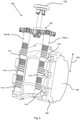
- ein erstes Ausführungsbeispiel einer Verstellmechanik;
- Fig. 3
- ein zweites Ausführungsbeispiel der Verstellmechanik;
- Fig. 4
- Teile eines dritten Ausführungsbeispiels der Verstellmechanik;
- Fig. 5
- ein zweites Verstellelement der Verstellmechanik aus
Fig. 4 . - In
Fig. 1 ist ein Triangulations-Lichttaster 10 (im Folgenden auch einfach Lichttaster genannt) und seine Funktionsweise schematisch dargestellt. Triangulations-Lichttaster dieser Art sind eine Art Distanzmesser, die feststellen können, ob ein Objekt 12 sich innerhalb oder außerhalb eines Schaltabstands befindet. - Der Lichttaster weist eine Lichtquelle 14 auf, die einen Sendelichtstrahl 16 in einen Überwachungsbereich 18 aussendet. Der Sendelichtstrahl 16 wird in der Regel durch eine Sendeoptik 18 gebündelt und fokussiert ausgesendet. Der Sendelichtstrahl 16 trifft auf ein Objekt 12, das in
Fig. 1 in vier verschiedenen Abständen vom Lichttaster 10 gestrichelt dargestellt ist. Das Objekt 12 ist in diesen Positionen mit den Bezugsziffern 12-1, 12-2, 12-3, 12-4 bezeichnet. - Weiter weist der Lichttaster 10 einen ortsauflösenden Empfänger 20 auf, der in diesem Ausführungsbeispiel als eine Anzahl aus in einer Zeilenrichtung angeordneten Fotodioden besteht. Die Zeilenrichtung ist die sogenannte Triangulationsrichtung und liegt in der Zeichenebene und auf der Verbindungslinie zwischen Lichtquelle 14 und Empfänger 20. Dem Empfänger 20 ist eine Empfangsoptik 22 vorgeordnet, die in diesem Ausführungsbeispiel als einfache Empfangslinse dargestellt ist.
- In dieser Anordnung werden die jeweiligen Reflexionen des Sendelichtstrahl 16 an dem Objekt 12 entsprechend den verschiedenen Positionen 12-1, 12-2, 12-3, 12-4 auf dem Empfänger 20 abgebildet. Für die Positionen 12-1, 12-2, 12-3, 12-4 ist dies durch jeweilige Empfangslichtstrahlen 24-1, 24-2, 24-3, 24-4 dargestellt.
- Weiter sind in Figur 12 Schaltabstände 30 und 32 dargestellt, von denen der Schaltabstand 30 nahe am Lichttaster 10 liegt und der Schaltabstand 32 weiter entfernt. In der Regel wird ein einziger bestimmter Schaltabstand am Lichttaster 10 eingestellt, um im späteren Arbeitsbetrieb detektieren zu können, ob das detektierte Objekt 12 innerhalb (das bezeichnet man dann als Nahbereich) oder außerhalb (Fernbereich) des Schaltabstands liegt, um dementsprechend ein Schaltsignal auszugeben. Zu dem jeweils gewählten Schaltabstand 30 oder 32 gehört nach dem Triangulationsprinzip ein Trennsteg auf dem in Triangulationsrichtung ortsauflösenden Empfänger 20. Die Lage dieses Trennsteges ist in
Figur 1 mit dem Bezugszeichen 34 für den Schaltabstand 30 bzw. mit 36 für den Schaltabstand 32 gekennzeichnet. - Die Lage des mit dem Schaltabstand korrespondierenden Trennsteges ist definiert durch den Schaltabstand, die Empfangsoptik 22 und der Position des Empfängers 20. Da die Position des Empfängers 20 in der Regel in einem Gehäuse des Lichttasters 10 festgelegt ist, kann der Schaltabstand 30 bzw. 32 also durch die Wahl des Trennsteges 34 bzw. 36 festgelegt werden. Für die Wahl des Trennsteges 34 bzw. 36 gibt es einerseits die Möglichkeit, diesen auf dem Empfänger 20 definieren zu können, zum Beispiel wenn der Empfänger 20 als eine Zeile mit einer Vielzahl von Fotodioden ausgebildet ist, die einzelnen auslesbar sind. Auf diese Weise können die Fotodioden auf der einen Seite des Trennsteges 34 bzw. 36 dem Nahbereich und die anderen dem Fernbereich zugeordnet werden. Häufig wird aber auch ein einfacherer Empfänger 20 eingesetzt, der beispielsweise lediglich aus zwei unmittelbar nebeneinander angeordneten Einzelempfängern besteht. Dann lässt sich der Schaltabstand 30 bzw. 32 durch Verschieben der Empfangsoptik 22 festlegen. Eine solche Einstellmöglichkeit ist durch den Doppelpfeil 40 angedeutet. Durch das Verschieben der Empfangsoptik 22 wird nämlich der Schwerpunkt des auftreffenden Lichts auf den Empfänger 20 verändert und kann deshalb so gelegt werden, dass genau im Schaltabstand 30 bzw. 32 gleich viel Licht auf Nah- wie Fernbereich fällt.
- Alternativ könnte in einer nicht dargestellten Ausführungsform gleichermaßen anstatt der Empfängerlinse mit der vorstehend beschriebenen Verstellmimik die Einzelempfänger (z.B. Fotodioden) oder die gesamte Fotodioden-Zeile selbst verschoben werden (die Empfängerlinse bliebe dann ortsfest).
- Wie aus
Figur 1 zu erkennen ist, ist eine Einstellung des kleineren Schaltabstands 30 erheblich weniger tolerant gegenüber Abweichungen als die Einstellung der Schaltabstands 32, der erheblich weiter entfernt liegt. Das liegt an dem Triangulationsprinzip, wie sich ausFigur 1 anhand der Empfangslichtstrahlen 24-1, 24-2 einerseits und 24-3, 24-4 andererseits sehr gut erkennen lässt. Im Nahbereich, also bei kleinen Schaltabständen, liegen die Schwerpunkte des Lichtempfangs der Reflektionen an den Objekten 12-1 und 12-2 erheblich weiter auseinander als im Fernbereich, bei Objekten 12-3 und 12-4, zwischen denen der gleiche relative Abstand besteht wie zwischen den Objekten 12-1 und 12-2. Wenn man den Schaltabstand 30 bzw. 32 also über eine Verstellung der Empfangsoptik 22 einstellen möchte, ist im Nahbereich lediglich eine gröbere Verstellung notwendig, im Fernbereich hingegen aber eine sehr feine Einstellung notwendig. - Die Erfindung betrifft jetzt im Kern die mechanische Ausbildung einer solchen Verstellmöglichkeit für eine optomechanische Anordnung, wie sie die Empfangsoptik 22 darstellt, die für den einen Bereich eine grobe und für den anderen Bereich eine feine Einstellung erlaubt. Im Weiteren wird eine Verstellmechanik 100 (
Fig. 2 bis 5 ) anhand eines Lichttasters beschrieben, bei dem eine Empfangsoptik 102 verstellt werden soll. Es soll aber bemerkt werden, dass die Erfindung nicht nur zum linearen Verschieben einer Empfangsoptik eingesetzt werden kann, sondern auch für andere optomechanische Anordnungen und auch nicht nur für lineares Verschieben, sondern zum Beispiel Verkippen oder dergleichen. - Die erfindungsgemäße Verstellmechanik 100 zum Verstellen der Empfangsoptik 102 umfasst ein erstes Verstellelement 104, das mit einem zweiten Verstellelement 106 zusammenwirkt. In dem Ausführungsbeispiel nach
Figur 2 ist das erste Verstellelement 104 in nicht näher dargestellter Weise in einem auch nicht dargestellten Gehäuse des Lichttasters drehbar, aber ansonsten ortsfest gelagert. Durch Drehen des ersten Verstellelements 104 erfolgt eine relative Verschiebung der beiden Verstellelemente 104 und 106 zueinander. In diesem Fall wird das zweite Verstellelement 106 linear in Richtung des Doppelpfeils 140 verschoben. Diese Verschiebung ist die zu erzielende Bewegung, um letztendlich den oben genannten Schaltabstand 30 bzw. 32 definiert einstellen zu können. - Das erste Verstellelement 104 weist ein erstes Gewinde 110 mit einer ersten Steigung und ein zweites Gewinde 112 mit anderer Steigung auf. Die Steigung des zweiten Gewindes 112 ist in diesem Ausführungsbeispiel feiner (kleiner) als die des ersten Gewindes 110. Beide Gewinde sind auf gleicher Achse angeordnet, so dass das erste Verstellelement 104 quasi wie eine Art Gewindestange mit verschiedenen Gewinden ausgebildet ist und das Verstellelement 104 in geeigneter Weise in dem Gehäuse gelagert ist. so dass erstes und zweites Gewinde auf der Achse in Verschieberichtung hintereinander liegen.
- Das zweite Verstellelement 106 ist in dem Gehäuse linear verschiebbar in Richtung des Doppelpfeils 108 gelagert. Es bildet eine Art Schlitten, an dem die Empfangsoptik 102 festgelegt ist. Weiter weist das zweite Verstellelement 106 einen Mitnehmer 114 auf, der in nur einen Gewindegang des ersten bzw. zweiten Gewindes 110 bzw. 112 mit einer entsprechend ausgebildeten Spitze 116 eingreift.
- Durch Drehen des ersten Verstellelements 104 wird der Mitnehmer 114 im jeweiligen Gewinde 110 bzw. 112 geführt, so dass diese Führung ein Verschieben des linear geführten, zweiten Verstellelements 106 bewirkt. Wenn der Mitnehmer 114 in das gröbere, erste Gewinde 110 eingreift, erfolgt eine Grobverstellung und wenn der Mitnehmer 114 in das feinere, zweite Gewinde 112 eingreift, erfolgt eine Feinverstellung. Dadurch, dass die beiden Gewinde auf der genannten Achse in Verschieberichtung 140 hintereinanderliegen, erfolgen die Feinverstellung und die Grobverstellung durch Drehen des einen Verstellelements 104 also nacheinander.
- Wenn das zweite Gewinde 112 sich nahtlos an das erste Gewinde 110 anschließt, wie dies in
Figur 2 dargestellt ist, geht die Grobverstellung stetig und monoton in die Feinverstellung über. Der Mitnehmer 114 ist dann über den gesamten Verstellweg der Verstellmechanik 100 mit einem der Gewinde 110 bzw. 112 in Eingriff. - Die beiden Gewinde 110 und 112 bilden ein zusammengehöriges Paar. Für eine bessere Führung der beiden Verstellelemente 104 und 106 zueinander ist bevorzugt vorgesehen, dass weitere Paare von erstem und zweiten Gewinde vorgesehen sind. In
Figur 2 sind zwei weitere Paare 120 und 122 dargestellt, wobei das zweite Verstellelement 106 jeweils weitere Mitnehmer 124 bzw. 126 für je ein Paar Gewinde aufweist. - Um das erste Verstellelement 104 drehen zu können, ist ein Bedienelement 130 vorgesehen, das ebenfalls in dem Gehäuse drehbar gelagert ist. Das Bedienelement 130 ist mit dem ersten Verstellelement 104 über ein untersetztes Schneckenradgetriebe 132 verbunden. Eine Bedienung über das extra vorgesehene Bedienelement 130 und das Getriebe 132 hat zwei wesentliche Vorteile. Zum einen wird bei der Betätigung des Bedienelements 130 mit der Hand oder mit einem Schraubendreher vermieden, dass axialer Druck auf das Verstellelement 104 und damit letztendlich auf die Empfangsoptik 102 ausgeübt werden kann. Der weitere Vorteil ist, dass durch die Untersetzung eine feinere Einstellung möglich ist.
- In einer nicht dargestellten Ausführungsform ist zusätzlich zu dem ersten und dem zweiten Gewinde ein weiteres Gewinde mit einer dritten Steigung vorgesehen, wodurch dann neben einer Grob- und einer Feinverstellung eine zwischen grob und fein liegende weitere Verstellmöglichkeit gegeben wäre.
- In einer in
Figur 3 dargestellten Ausführungsform der Verstellmechanik 100 sind zwei erste Verstellelemente 104-A und 104-B vorgesehen und das zweite Verstellelement 106 weist eine entsprechende Anzahl Mitnehmer 114 auf. - In den
Figuren 4 und 5 sind Teile einer weiteren Ausführungsform dargestellt, in der das erste Verstellelement 204 und das zweite Verstellelement 206 etwas anders ausgebildet sind, wobei das Funktionsprinzip aber das gleiche ist. - Das erste Verstellelement 204 weist wiederum ein erstes Gewinde 210 und ein zweites Gewinde 212 mit den entsprechenden unterschiedlichen Steigungen auf, die in diesem Ausführungsbeispiel als Außengewinde ausgeführt sind. Die beiden Außengewinde 210 und 212 haben zueinander einen axialen Abstand a. Das erste Außengewinde 210 hat einen kleineren Durchmesser als das zweite Außengewinde 212. Das erste Verstellelement 206 ist also wiederum nach Art einer Gewindestange mit unterschiedlichen Gewinden ausgebildet.
- Das zweite Verstellelement 206 dient jetzt zur Aufnahme des ersten Verstellelements 204. Dazu umfasst das zweite Verstellelement 206 ein erstes Innengewinde 220 mit der ersten Steigung zur Aufnahme des ersten Außengewindes 210 und ein zweites Innengewinde 222 mit der zweiten Steigung zur Aufnahme des zweiten Außengewindes 212 auf. Beide Innengewinde 220 und 222 liegen auf gleicher Achse. Das Innengewinde 220 hat ein dem Außendurchmesser des Außengewindes 210 entsprechenden Durchmesser und das Innengewinde 222 hat ein dem Durchmesser des Außengewindes 212 entsprechenden Durchmesser. Die einzelnen Gewindegänge der Innengewinde 220 und 222 sind in der schematischen
Fig. 4 nicht dargestellt. Die Innengewinde 220 und 222 bilden hier die Mitnehmer 114 wie in der ersten bzw. zweiten Ausführungsform nachFiguren 2 bzw. 3, weil sie die gleiche Funktion haben wie die Mitnehmer 114. - Die Außengewinde 210 und 212 haben einen axialen Abstand zueinander, der der axialen Gesamtlänge der beiden Innengewinde 220 und 222 entspricht. Dann schraubt sich nämlich das zweite Außengewinde 212 in das zweite Innengewinde 222, wenn die ersten Gewinde 210 und 220 sich voneinander lösen.
- Die Innengewinde 220 und 222 sind in zwei gegenüberliegende Backen 230 und 232 vorgesehen, wobei jede Backe einen Teil des ersten Innengewindes 220 und einen Teil des zweiten Innengewindes 222 aufweist, so dass das erste Verstellelement 204 zwischen die Backen 230 und 232 mit seinen Außengewinden 210 und 212 eingreifen kann. Beim Übergang von Grob- zur Feinverstellung haben dann die Backen die Möglichkeit, ein wenig nachzugeben, um mechanische Fertigungstoleranzen auszugleichen.
Claims (15)
- Optoelektronischer Sensor mit einer optomechanischen Anordnung (22, 102,) zum Aussenden, Empfangen oder Umlenken von Lichtstrahlen (16, 24) mit einer Verstellmechanik (100) zum Verstellen der optomechanischen Anordnung (102), wobei die Verstellmechanik (100) ein erstes Verstellelement (104; 204), das mit einem zweiten Verstellelement (106; 206) zusammenwirkt, aufweist, wobei durch Drehen des ersten Verstellelements (104; 204) eine relative Verschiebung (40; 140) der beiden Verstellelemente (104, 106; 204, 206) zueinander erfolgt,dadurch gekennzeichnet,dass das erste Verstellelement (104; 204) ein erstes Gewinde (110; 210) mit einer ersten Steigung und ein zweites Gewinde (112; 212) mit anderer Steigung aufweist, wobei das zweite Gewinde (112; 212) auf gleicher Achse wie das erste Gewinde (110; 210) liegt, so dass das erste Verstellelement (104; 204) nach Art einer Gewindestange mit verschiedenen Gewinden ausgebildet ist und erstes und zweites Gewinde (110, 112; 210, 212) auf der Achse in Verschieberichtung (40; 140) hintereinander liegen,und dass das zweite Verstellelement (106; 206) einen Mitnehmer (114; 220, 222) aufweist, der zur Grobverstellung der optomechanischen Anordnung (22, 102) in das Gewinde (110; 210) mit größerer Steigung eingreift und zur Feinverstellung in das Gewinde (112; 212) mit kleinerer Steigung eingreift.
- Sensor nach Anspruch 1, dadurch gekennzeichnet, dass über den gesamten Verstellweg der Verstellmechanik der Mitnehmer mit einem der Gewinde in Eingriff ist.
- Sensor nach Anspruch 1, dadurch gekennzeichnet, dass der Mitnehmer nur in einen einzigen Gewindegang des ersten oder zweiten Gewindes eingreift.
- Sensor nach Anspruch 3, dadurch gekennzeichnet, dass die Steigung des ersten Gewindes kontinuierlich, also stetig und monoton, in die Steigung des zweiten Gewindes übergeht.
- Sensor nach einem vorhergehenden Ansprüche 1 oder 2, dadurch gekennzeichnet, dass der Mitnehmer ein erstes Innengewinde mit der ersten Steigung zur Aufnahme des ersten, als Außengewinde ausgeführten Gewindes aufweist und ein zweites Innengewinde mit der zweiten Steigung aufweist zur Aufnahme des zweiten, als Außengewinde ausgeführten Gewindes aufweist, wobei das zweite Innengewinde auf gleicher Achse wie das erste liegt.
- Sensor nach Anspruch 5, dadurch gekennzeichnet, dass die Außengewinde einen axialen Abstand zueinander haben, der der axialen Gesamtlänge der beiden Innengewinde entspricht.
- Sensor nach einem der vorhergehenden Ansprüche 5 bis 6, dadurch gekennzeichnet, dass die ersten Gewinde einen kleineren Durchmesser haben als die zweiten Gewinde.
- Sensor nach einem der vorhergehenden Ansprüche 5 bis 7, dadurch gekennzeichnet, dass der Mitnehmer zwei gegenüberliegende Backen aufweist, wobei jede Backe einen Teil des ersten und einen Teil des zweiten Innengewindes aufweist, so dass das erste Verstellelement zwischen die Backen mit seinen Außengewinden eingreifen kann.
- Sensor nach einem der vorhergehenden Ansprüche, dadurch gekennzeichnet, dass mehrere Paare von erstem und zweiten Gewinde vorgesehen sind, wobei das zweite Verstellelement jeweils einen Mitnehmer für je ein Paar Gewinde aufweist.
- Sensor nach einem der vorhergehenden Ansprüche, dadurch gekennzeichnet, dass das erste Verstellelement von Hand bedienbar ist.
- Sensor nach Anspruch 10, dadurch gekennzeichnet, dass das erste Verstellelement über ein untersetztes Getriebe bedienbar ist.
- Sensor nach einem der vorhergehenden Ansprüche, dadurch gekennzeichnet, dass das erste Verstellelement axial ortsfest in einem Sensorgehäuse angeordnet ist und die optomechanische Anordnung an das zweite Verstellelement angekoppelt ist, das axial beweglich gelagert ist, um eine Verstellung der optischen Anordnung relativ zum Sensorgehäuse zu bewirken.
- Sensor nach einem der vorhergehenden Ansprüche, dadurch gekennzeichnet, dass das erste Verstellelement ein drittes Gewinde aufweist, wobei die Steigung des dritten Gewindes eine andere ist als die der ersten und zweiten Gewinde.
- Sensor nach einem der vorhergehenden Ansprüche, dadurch gekennzeichnet, dass dieser als Triangulations-Lichttaster ausgebildet ist und die optomechanische Anordnung durch eine Empfangsoptik gebildet ist und die Sendelichtstrahlen in den Überwachungsbereich gerichtet sind und der Lichtempfänger mehrere Empfangsbereiche umfasst, die jeweils Empfangssignale ausgeben, wobei die Empfangsbereiche unterschiedlichen Objektabständen zugeordnet sind und zu diesem Zweck derart angeordnet sind, dass je nach Abstand des zu erfassenden Objekts vom Triangulations-Lichttaster unterschiedliche Empfangsbereiche von remittiertem Empfangslicht beaufschlagt werden.
- Sensor nach Anspruch 14, dadurch gekennzeichnet, dass eine Empfangsfläche des Lichtempfängers in einen Nahbereich und einen Fernbereich unterteilt ist und das Gewinde mit größerer Steigung einer Verstellung im Nahbereich und die Gewinde mit kleinerer Steigung einer Verstellung im Fernbereich zugeordnet sind.
Applications Claiming Priority (1)
| Application Number | Priority Date | Filing Date | Title |
|---|---|---|---|
| DE102020120564.3A DE102020120564B4 (de) | 2020-08-04 | 2020-08-04 | Optoelektronischer Sensor, insbesondere Triangulations-Lichttaster |
Publications (2)
| Publication Number | Publication Date |
|---|---|
| EP3951310A1 true EP3951310A1 (de) | 2022-02-09 |
| EP3951310B1 EP3951310B1 (de) | 2022-07-06 |
Family
ID=76890820
Family Applications (1)
| Application Number | Title | Priority Date | Filing Date |
|---|---|---|---|
| EP21184947.6A Active EP3951310B1 (de) | 2020-08-04 | 2021-07-12 | Optoelektronischer sensor, insbesondere triangulations-lichttaster |
Country Status (2)
| Country | Link |
|---|---|
| EP (1) | EP3951310B1 (de) |
| DE (1) | DE102020120564B4 (de) |
Citations (4)
| Publication number | Priority date | Publication date | Assignee | Title |
|---|---|---|---|---|
| JPH0643610U (ja) * | 1992-11-20 | 1994-06-10 | ミノルタカメラ株式会社 | レンズ移動装置 |
| EP0801315A1 (de) * | 1996-04-12 | 1997-10-15 | Datalogic S.P.A. | Elektro-optisches Gerät zur Erkennung der Anwesenheit eines Gegenstands in einstellbarem Abstand, mit Hintergrundausblendung |
| US20050085838A1 (en) * | 2003-02-25 | 2005-04-21 | Bennie Thompson | Method of operating a biopsy device |
| WO2006057028A1 (en) | 2004-11-29 | 2006-06-01 | Davide Agnetti | Device for moving components, particularly in optical systems |
Family Cites Families (1)
| Publication number | Priority date | Publication date | Assignee | Title |
|---|---|---|---|---|
| JPH06168652A (ja) * | 1992-11-27 | 1994-06-14 | Omron Corp | 距離設定形光電スイッチ |
-
2020
- 2020-08-04 DE DE102020120564.3A patent/DE102020120564B4/de not_active Expired - Fee Related
-
2021
- 2021-07-12 EP EP21184947.6A patent/EP3951310B1/de active Active
Patent Citations (4)
| Publication number | Priority date | Publication date | Assignee | Title |
|---|---|---|---|---|
| JPH0643610U (ja) * | 1992-11-20 | 1994-06-10 | ミノルタカメラ株式会社 | レンズ移動装置 |
| EP0801315A1 (de) * | 1996-04-12 | 1997-10-15 | Datalogic S.P.A. | Elektro-optisches Gerät zur Erkennung der Anwesenheit eines Gegenstands in einstellbarem Abstand, mit Hintergrundausblendung |
| US20050085838A1 (en) * | 2003-02-25 | 2005-04-21 | Bennie Thompson | Method of operating a biopsy device |
| WO2006057028A1 (en) | 2004-11-29 | 2006-06-01 | Davide Agnetti | Device for moving components, particularly in optical systems |
Also Published As
| Publication number | Publication date |
|---|---|
| DE102020120564B4 (de) | 2024-05-16 |
| DE102020120564A1 (de) | 2022-02-10 |
| EP3951310B1 (de) | 2022-07-06 |
Similar Documents
| Publication | Publication Date | Title |
|---|---|---|
| DE3513671C2 (de) | ||
| EP0509979B1 (de) | Photoelektronische Positionsmesseinrichtung | |
| EP3640667B1 (de) | Optoelektronischer sensor und verfahren zur erfassung von objekten | |
| DE10330985A1 (de) | Vorrichtung zur Verabreichung eines fluiden Produkts mit optischer Abtastung | |
| EP3367155B1 (de) | Vorrichtung zur erfassung eines stereobilds | |
| EP1884804A1 (de) | Entfernungsmessgerät | |
| DE102021111949B4 (de) | Vorrichtung zur scannenden Messung des Abstands zu einem Objekt | |
| DE29817668U1 (de) | Vorrichtung zum Erfassen von Schaltstellungen eines mechanisch betätigbaren Schaltmittels | |
| EP2112540A1 (de) | Identifikationseinrichtung zur linienförmigen Erfassung eines in einer Objektebene angeordneten Codes | |
| EP3951310B1 (de) | Optoelektronischer sensor, insbesondere triangulations-lichttaster | |
| EP1467185A1 (de) | Linsenanordnung für einen optischen Encoder | |
| DE2410744B2 (de) | Zoomobjektiv | |
| EP0115267A2 (de) | Abbildungssystem | |
| DE10323088A1 (de) | Positionsmesseinrichtung | |
| DE202020104499U1 (de) | Optoelektronischer Sensor, insbesondere Triangulations-Lichttaster | |
| DE3044416C2 (de) | Automatische Fokussiereinrichtung | |
| DE1299894B (de) | Messvorrichtung zur Bestimmung der Relativbewegung zweier Objekte | |
| EP4343382B1 (de) | Optoelektronischer sensor | |
| EP3807688B1 (de) | Strahlaufweiter und verfahren zum betreiben eines strahlaufweiters | |
| DE102018209394A1 (de) | Koaxiales LiDAR-System | |
| EP3495845A1 (de) | Optoelektronischer sensor und verfahren zur erfassung eines überwachungsbereichs | |
| DE2455407C3 (de) | Vorrichtung zum Scharfeinstellen eines optischen Systems durch Kontraststärkemessung | |
| DE102017127368A1 (de) | Bedienvorrichtung mit fokussierendem Bedienelement | |
| EP0932819B1 (de) | Optische positionsmesseinrichtung | |
| EP2017653A1 (de) | Optoelektronischer Sensor und Empfangsverfahren mit Störlichtkorrektur |
Legal Events
| Date | Code | Title | Description |
|---|---|---|---|
| PUAI | Public reference made under article 153(3) epc to a published international application that has entered the european phase |
Free format text: ORIGINAL CODE: 0009012 |
|
| STAA | Information on the status of an ep patent application or granted ep patent |
Free format text: STATUS: REQUEST FOR EXAMINATION WAS MADE |
|
| 17P | Request for examination filed |
Effective date: 20211221 |
|
| AK | Designated contracting states |
Kind code of ref document: A1 Designated state(s): AL AT BE BG CH CY CZ DE DK EE ES FI FR GB GR HR HU IE IS IT LI LT LU LV MC MK MT NL NO PL PT RO RS SE SI SK SM TR |
|
| RIC1 | Information provided on ipc code assigned before grant |
Ipc: G01V 8/12 20060101ALI20220404BHEP Ipc: G01S 7/481 20060101ALI20220404BHEP Ipc: G01S 17/48 20060101ALI20220404BHEP Ipc: G01B 11/02 20060101ALI20220404BHEP Ipc: G01B 5/00 20060101AFI20220404BHEP |
|
| GRAP | Despatch of communication of intention to grant a patent |
Free format text: ORIGINAL CODE: EPIDOSNIGR1 |
|
| STAA | Information on the status of an ep patent application or granted ep patent |
Free format text: STATUS: GRANT OF PATENT IS INTENDED |
|
| GRAS | Grant fee paid |
Free format text: ORIGINAL CODE: EPIDOSNIGR3 |
|
| GRAA | (expected) grant |
Free format text: ORIGINAL CODE: 0009210 |
|
| STAA | Information on the status of an ep patent application or granted ep patent |
Free format text: STATUS: THE PATENT HAS BEEN GRANTED |
|
| INTG | Intention to grant announced |
Effective date: 20220513 |
|
| AK | Designated contracting states |
Kind code of ref document: B1 Designated state(s): AL AT BE BG CH CY CZ DE DK EE ES FI FR GB GR HR HU IE IS IT LI LT LU LV MC MK MT NL NO PL PT RO RS SE SI SK SM TR |
|
| REG | Reference to a national code |
Ref country code: AT Ref legal event code: REF Ref document number: 1503132 Country of ref document: AT Kind code of ref document: T Effective date: 20220715 Ref country code: CH Ref legal event code: EP |
|
| REG | Reference to a national code |
Ref country code: DE Ref legal event code: R096 Ref document number: 502021000066 Country of ref document: DE |
|
| REG | Reference to a national code |
Ref country code: IE Ref legal event code: FG4D Free format text: LANGUAGE OF EP DOCUMENT: GERMAN |
|
| REG | Reference to a national code |
Ref country code: LT Ref legal event code: MG9D |
|
| REG | Reference to a national code |
Ref country code: NL Ref legal event code: MP Effective date: 20220706 |
|
| PG25 | Lapsed in a contracting state [announced via postgrant information from national office to epo] |
Ref country code: SE Free format text: LAPSE BECAUSE OF FAILURE TO SUBMIT A TRANSLATION OF THE DESCRIPTION OR TO PAY THE FEE WITHIN THE PRESCRIBED TIME-LIMIT Effective date: 20220706 Ref country code: RS Free format text: LAPSE BECAUSE OF FAILURE TO SUBMIT A TRANSLATION OF THE DESCRIPTION OR TO PAY THE FEE WITHIN THE PRESCRIBED TIME-LIMIT Effective date: 20220706 Ref country code: PT Free format text: LAPSE BECAUSE OF FAILURE TO SUBMIT A TRANSLATION OF THE DESCRIPTION OR TO PAY THE FEE WITHIN THE PRESCRIBED TIME-LIMIT Effective date: 20221107 Ref country code: NO Free format text: LAPSE BECAUSE OF FAILURE TO SUBMIT A TRANSLATION OF THE DESCRIPTION OR TO PAY THE FEE WITHIN THE PRESCRIBED TIME-LIMIT Effective date: 20221006 Ref country code: NL Free format text: LAPSE BECAUSE OF FAILURE TO SUBMIT A TRANSLATION OF THE DESCRIPTION OR TO PAY THE FEE WITHIN THE PRESCRIBED TIME-LIMIT Effective date: 20220706 Ref country code: LV Free format text: LAPSE BECAUSE OF FAILURE TO SUBMIT A TRANSLATION OF THE DESCRIPTION OR TO PAY THE FEE WITHIN THE PRESCRIBED TIME-LIMIT Effective date: 20220706 Ref country code: LT Free format text: LAPSE BECAUSE OF FAILURE TO SUBMIT A TRANSLATION OF THE DESCRIPTION OR TO PAY THE FEE WITHIN THE PRESCRIBED TIME-LIMIT Effective date: 20220706 Ref country code: FI Free format text: LAPSE BECAUSE OF FAILURE TO SUBMIT A TRANSLATION OF THE DESCRIPTION OR TO PAY THE FEE WITHIN THE PRESCRIBED TIME-LIMIT Effective date: 20220706 Ref country code: ES Free format text: LAPSE BECAUSE OF FAILURE TO SUBMIT A TRANSLATION OF THE DESCRIPTION OR TO PAY THE FEE WITHIN THE PRESCRIBED TIME-LIMIT Effective date: 20220706 |
|
| PG25 | Lapsed in a contracting state [announced via postgrant information from national office to epo] |
Ref country code: PL Free format text: LAPSE BECAUSE OF FAILURE TO SUBMIT A TRANSLATION OF THE DESCRIPTION OR TO PAY THE FEE WITHIN THE PRESCRIBED TIME-LIMIT Effective date: 20220706 Ref country code: IS Free format text: LAPSE BECAUSE OF FAILURE TO SUBMIT A TRANSLATION OF THE DESCRIPTION OR TO PAY THE FEE WITHIN THE PRESCRIBED TIME-LIMIT Effective date: 20221106 Ref country code: HR Free format text: LAPSE BECAUSE OF FAILURE TO SUBMIT A TRANSLATION OF THE DESCRIPTION OR TO PAY THE FEE WITHIN THE PRESCRIBED TIME-LIMIT Effective date: 20220706 Ref country code: GR Free format text: LAPSE BECAUSE OF FAILURE TO SUBMIT A TRANSLATION OF THE DESCRIPTION OR TO PAY THE FEE WITHIN THE PRESCRIBED TIME-LIMIT Effective date: 20221007 |
|
| REG | Reference to a national code |
Ref country code: DE Ref legal event code: R097 Ref document number: 502021000066 Country of ref document: DE |
|
| PG25 | Lapsed in a contracting state [announced via postgrant information from national office to epo] |
Ref country code: SM Free format text: LAPSE BECAUSE OF FAILURE TO SUBMIT A TRANSLATION OF THE DESCRIPTION OR TO PAY THE FEE WITHIN THE PRESCRIBED TIME-LIMIT Effective date: 20220706 Ref country code: RO Free format text: LAPSE BECAUSE OF FAILURE TO SUBMIT A TRANSLATION OF THE DESCRIPTION OR TO PAY THE FEE WITHIN THE PRESCRIBED TIME-LIMIT Effective date: 20220706 Ref country code: MC Free format text: LAPSE BECAUSE OF FAILURE TO SUBMIT A TRANSLATION OF THE DESCRIPTION OR TO PAY THE FEE WITHIN THE PRESCRIBED TIME-LIMIT Effective date: 20220706 Ref country code: DK Free format text: LAPSE BECAUSE OF FAILURE TO SUBMIT A TRANSLATION OF THE DESCRIPTION OR TO PAY THE FEE WITHIN THE PRESCRIBED TIME-LIMIT Effective date: 20220706 Ref country code: CZ Free format text: LAPSE BECAUSE OF FAILURE TO SUBMIT A TRANSLATION OF THE DESCRIPTION OR TO PAY THE FEE WITHIN THE PRESCRIBED TIME-LIMIT Effective date: 20220706 |
|
| PLBE | No opposition filed within time limit |
Free format text: ORIGINAL CODE: 0009261 |
|
| STAA | Information on the status of an ep patent application or granted ep patent |
Free format text: STATUS: NO OPPOSITION FILED WITHIN TIME LIMIT |
|
| PG25 | Lapsed in a contracting state [announced via postgrant information from national office to epo] |
Ref country code: SK Free format text: LAPSE BECAUSE OF FAILURE TO SUBMIT A TRANSLATION OF THE DESCRIPTION OR TO PAY THE FEE WITHIN THE PRESCRIBED TIME-LIMIT Effective date: 20220706 Ref country code: EE Free format text: LAPSE BECAUSE OF FAILURE TO SUBMIT A TRANSLATION OF THE DESCRIPTION OR TO PAY THE FEE WITHIN THE PRESCRIBED TIME-LIMIT Effective date: 20220706 |
|
| 26N | No opposition filed |
Effective date: 20230411 |
|
| PG25 | Lapsed in a contracting state [announced via postgrant information from national office to epo] |
Ref country code: AL Free format text: LAPSE BECAUSE OF FAILURE TO SUBMIT A TRANSLATION OF THE DESCRIPTION OR TO PAY THE FEE WITHIN THE PRESCRIBED TIME-LIMIT Effective date: 20220706 |
|
| REG | Reference to a national code |
Ref country code: BE Ref legal event code: MM Effective date: 20230731 |
|
| PG25 | Lapsed in a contracting state [announced via postgrant information from national office to epo] |
Ref country code: LU Free format text: LAPSE BECAUSE OF NON-PAYMENT OF DUE FEES Effective date: 20230712 |
|
| PG25 | Lapsed in a contracting state [announced via postgrant information from national office to epo] |
Ref country code: LU Free format text: LAPSE BECAUSE OF NON-PAYMENT OF DUE FEES Effective date: 20230712 |
|
| REG | Reference to a national code |
Ref country code: IE Ref legal event code: MM4A |
|
| PG25 | Lapsed in a contracting state [announced via postgrant information from national office to epo] |
Ref country code: BE Free format text: LAPSE BECAUSE OF NON-PAYMENT OF DUE FEES Effective date: 20230731 |
|
| PG25 | Lapsed in a contracting state [announced via postgrant information from national office to epo] |
Ref country code: IE Free format text: LAPSE BECAUSE OF NON-PAYMENT OF DUE FEES Effective date: 20230712 |
|
| PG25 | Lapsed in a contracting state [announced via postgrant information from national office to epo] |
Ref country code: IE Free format text: LAPSE BECAUSE OF NON-PAYMENT OF DUE FEES Effective date: 20230712 Ref country code: BG Free format text: LAPSE BECAUSE OF FAILURE TO SUBMIT A TRANSLATION OF THE DESCRIPTION OR TO PAY THE FEE WITHIN THE PRESCRIBED TIME-LIMIT Effective date: 20220706 |
|
| REG | Reference to a national code |
Ref country code: CH Ref legal event code: PL |
|
| PG25 | Lapsed in a contracting state [announced via postgrant information from national office to epo] |
Ref country code: CH Free format text: LAPSE BECAUSE OF NON-PAYMENT OF DUE FEES Effective date: 20240731 |
|
| PG25 | Lapsed in a contracting state [announced via postgrant information from national office to epo] |
Ref country code: CY Free format text: LAPSE BECAUSE OF FAILURE TO SUBMIT A TRANSLATION OF THE DESCRIPTION OR TO PAY THE FEE WITHIN THE PRESCRIBED TIME-LIMIT; INVALID AB INITIO Effective date: 20210712 |
|
| PG25 | Lapsed in a contracting state [announced via postgrant information from national office to epo] |
Ref country code: HU Free format text: LAPSE BECAUSE OF FAILURE TO SUBMIT A TRANSLATION OF THE DESCRIPTION OR TO PAY THE FEE WITHIN THE PRESCRIBED TIME-LIMIT; INVALID AB INITIO Effective date: 20210712 |
|
| PGFP | Annual fee paid to national office [announced via postgrant information from national office to epo] |
Ref country code: DE Payment date: 20250722 Year of fee payment: 5 |
|
| PGFP | Annual fee paid to national office [announced via postgrant information from national office to epo] |
Ref country code: IT Payment date: 20250731 Year of fee payment: 5 |
|
| PGFP | Annual fee paid to national office [announced via postgrant information from national office to epo] |
Ref country code: FR Payment date: 20250723 Year of fee payment: 5 Ref country code: AT Payment date: 20251020 Year of fee payment: 5 |
|
| PG25 | Lapsed in a contracting state [announced via postgrant information from national office to epo] |
Ref country code: TR Free format text: LAPSE BECAUSE OF FAILURE TO SUBMIT A TRANSLATION OF THE DESCRIPTION OR TO PAY THE FEE WITHIN THE PRESCRIBED TIME-LIMIT Effective date: 20220706 |
|
| PG25 | Lapsed in a contracting state [announced via postgrant information from national office to epo] |
Ref country code: SI Free format text: LAPSE BECAUSE OF FAILURE TO SUBMIT A TRANSLATION OF THE DESCRIPTION OR TO PAY THE FEE WITHIN THE PRESCRIBED TIME-LIMIT Effective date: 20220706 |
|
| GBPC | Gb: european patent ceased through non-payment of renewal fee |
Effective date: 20250712 |
|
| PG25 | Lapsed in a contracting state [announced via postgrant information from national office to epo] |
Ref country code: GB Free format text: LAPSE BECAUSE OF NON-PAYMENT OF DUE FEES Effective date: 20250712 |