EP3951289A1 - Ice crushing device and refrigerator having same - Google Patents
Ice crushing device and refrigerator having same Download PDFInfo
- Publication number
- EP3951289A1 EP3951289A1 EP19921143.4A EP19921143A EP3951289A1 EP 3951289 A1 EP3951289 A1 EP 3951289A1 EP 19921143 A EP19921143 A EP 19921143A EP 3951289 A1 EP3951289 A1 EP 3951289A1
- Authority
- EP
- European Patent Office
- Prior art keywords
- ice crushing
- disposed
- gear
- accommodation cavity
- crushing device
- Prior art date
- Legal status (The legal status is an assumption and is not a legal conclusion. Google has not performed a legal analysis and makes no representation as to the accuracy of the status listed.)
- Granted
Links
Images




Classifications
-
- F—MECHANICAL ENGINEERING; LIGHTING; HEATING; WEAPONS; BLASTING
- F25—REFRIGERATION OR COOLING; COMBINED HEATING AND REFRIGERATION SYSTEMS; HEAT PUMP SYSTEMS; MANUFACTURE OR STORAGE OF ICE; LIQUEFACTION SOLIDIFICATION OF GASES
- F25C—PRODUCING, WORKING OR HANDLING ICE
- F25C5/00—Working or handling ice
- F25C5/20—Distributing ice
- F25C5/22—Distributing ice particularly adapted for household refrigerators
-
- F—MECHANICAL ENGINEERING; LIGHTING; HEATING; WEAPONS; BLASTING
- F25—REFRIGERATION OR COOLING; COMBINED HEATING AND REFRIGERATION SYSTEMS; HEAT PUMP SYSTEMS; MANUFACTURE OR STORAGE OF ICE; LIQUEFACTION SOLIDIFICATION OF GASES
- F25C—PRODUCING, WORKING OR HANDLING ICE
- F25C5/00—Working or handling ice
- F25C5/02—Apparatus for disintegrating, removing or harvesting ice
- F25C5/04—Apparatus for disintegrating, removing or harvesting ice without the use of saws
- F25C5/046—Ice-crusher machines
-
- F—MECHANICAL ENGINEERING; LIGHTING; HEATING; WEAPONS; BLASTING
- F25—REFRIGERATION OR COOLING; COMBINED HEATING AND REFRIGERATION SYSTEMS; HEAT PUMP SYSTEMS; MANUFACTURE OR STORAGE OF ICE; LIQUEFACTION SOLIDIFICATION OF GASES
- F25D—REFRIGERATORS; COLD ROOMS; ICE-BOXES; COOLING OR FREEZING APPARATUS NOT OTHERWISE PROVIDED FOR
- F25D21/00—Defrosting; Preventing frosting; Removing condensed or defrost water
- F25D21/04—Preventing the formation of frost or condensate
-
- F—MECHANICAL ENGINEERING; LIGHTING; HEATING; WEAPONS; BLASTING
- F25—REFRIGERATION OR COOLING; COMBINED HEATING AND REFRIGERATION SYSTEMS; HEAT PUMP SYSTEMS; MANUFACTURE OR STORAGE OF ICE; LIQUEFACTION SOLIDIFICATION OF GASES
- F25D—REFRIGERATORS; COLD ROOMS; ICE-BOXES; COOLING OR FREEZING APPARATUS NOT OTHERWISE PROVIDED FOR
- F25D21/00—Defrosting; Preventing frosting; Removing condensed or defrost water
- F25D21/14—Collecting or removing condensed and defrost water; Drip trays
-
- F—MECHANICAL ENGINEERING; LIGHTING; HEATING; WEAPONS; BLASTING
- F25—REFRIGERATION OR COOLING; COMBINED HEATING AND REFRIGERATION SYSTEMS; HEAT PUMP SYSTEMS; MANUFACTURE OR STORAGE OF ICE; LIQUEFACTION SOLIDIFICATION OF GASES
- F25D—REFRIGERATORS; COLD ROOMS; ICE-BOXES; COOLING OR FREEZING APPARATUS NOT OTHERWISE PROVIDED FOR
- F25D23/00—General constructional features
- F25D23/02—Doors; Covers
- F25D23/04—Doors; Covers with special compartments, e.g. butter conditioners
-
- F—MECHANICAL ENGINEERING; LIGHTING; HEATING; WEAPONS; BLASTING
- F25—REFRIGERATION OR COOLING; COMBINED HEATING AND REFRIGERATION SYSTEMS; HEAT PUMP SYSTEMS; MANUFACTURE OR STORAGE OF ICE; LIQUEFACTION SOLIDIFICATION OF GASES
- F25D—REFRIGERATORS; COLD ROOMS; ICE-BOXES; COOLING OR FREEZING APPARATUS NOT OTHERWISE PROVIDED FOR
- F25D23/00—General constructional features
- F25D23/02—Doors; Covers
- F25D23/028—Details
Definitions
- the present invention relates to the field of household appliances and particularly to an ice crushing device and a refrigerator having the same.
- the ice maker of the refrigerator comprises an ice making device and an ice crushing device.
- the ice making device prepares ice cubes and then stores them in a barrel-shaped container.
- the ice crushing device is used to crush ice to facilitate access by users.
- a transmission mode adopted by the ice maker of the refrigerator is that a motor drives a rotatable bucket of the ice crushing device to rotate through the transmission of a bevel gear and a spur gear, with a low transmission efficiency. Since the ice crushing motor and the transmission mechanism are located below the ice storage box, crushed ice is liable to fall into a gap between the gears, which will affect the transmission and cause the gears to adhere. When the ice maker fails when water is filled, the failure is prone to cause continuous water filling into the ice maker. At this time, water is prone to accumulate in an installation cavity of the ice crushing motor, thereby causing motor failure and safety hazards.
- the accumulated water will flow along an air duct of the refrigerator to the cabinet and is prone to cause damages to an evaporator of the refrigerator.
- the surface of the ice maker is prone to condensation, which reduces the user experience.
- An object of the present invention is to provide an ice crushing device and a refrigerator having the same, to solve problems with conventional refrigerators that the ice maker has a low transmission efficiency , the crushed ice is prone to cause adhesion of gears, and the accumulated water is apt to cause damages to the motor and evaporator, and thereby improving the convenience in using the refrigerator.
- the present invention provides an ice crushing device disposed on a door body of the refrigerator, the door body being provided with a first accommodation cavity and a second accommodation cavity with an opening;
- the ice crushing device comprises: an ice crushing bucket disposed in the first accommodation cavity, a cutter head disposed in the ice crushing bucket, and a driving unit at least partially disposed in the second accommodation cavity, the driving unit comprising: a driving rod connected to the cutter head and driving the cutter head to rotate in the ice crushing bucket, a gear set connected to and acting on the driving rod, and a motor for driving the gear set to operate; wherein an edge of the door body is provided with a heating wire;
- the ice crushing device further comprises: a cover plate for closing the opening of the second accommodation cavity so that the second accommodation cavity is formed as a closed space, and a first drain pipe communicating the second accommodation cavity with a refrigeration compartment of the refrigerator; the cover plate is sealingly connected with the opening by a waterproof flange and a waterproof groove that fit with each other;
- the gear set comprises: a first gear sleeved on an outer circumference of the ice crushing bucket, and a second gear that meshes with the first gear to indirectly drive the cutter head to rotate; wherein the first gear is disposed at an upper end of the ice crushing bucket and coaxial with the driving rod, a central axis of the second gear is parallel to the driving rod, and the motor drives the second gear to rotate.
- the gear set further comprises: a connection box fixedly disposed in the first accommodation cavity, the connection box comprising: a first box body receiving the first gear, and a second box body receiving the second gear and connected to the first box body; the first box body and the second box body share a side wall, and the side wall is at least partially hollowed out to form a hollow portion, and the first gear and the second gear are in meshing connection with each other through the hollow portion.
- the second box body comprises an upper cover and a lower cover that are detachably provided with each other, an upper edge of the lower cover is disposed lower than an upper edge of the first box body, and the second gear is disposed in the accommodation cavity formed between the upper cover and the lower cover.
- an upper end edge of the opening constitutes the waterproof flange
- the cover plate comprises: a cover plate body, an extension wall extending from the edge of the cover plate body perpendicularly towards the opening, a first waterproof block disposed extending from the extension wall away from the end of the cover plate body, and a second waterproof block disposed on an end face of the first waterproof block away from the opening;
- the waterproof groove is provided in a portion shared by the first waterproof block and second waterproof block, and provided on an end face of the first waterproof block towards the opening; a depth of the waterproof groove is not smaller than a height of the first waterproof block.
- a sealing ring is provided on a peripheral side of the door body, the heating wire is arranged around the sealing ring and at least partially forms a first gap with the sealing ring, and the other end hole of the first drain pipe is disposed in the first gap.
- the ice crushing device further comprises an ice outlet channel communicating the ice crushing bucket with the outside of the door body; a second drain pipe communicated with the ice outlet channel is provided on the side wall of the ice outlet channel, and the other end hole of the second drain pipe is exposed to the refrigeration compartment and disposed close to the heating wire.
- the heating wire and the sealing ring further form a second gap, and the other end hole of the second drain pipe is disposed in the second gap.
- a third drain pipe communicated with the first accommodation cavity is provided at the bottom of the first accommodation cavity, and the other end hole of the third drain pipe is exposed to a lower air duct on the door body.
- the present invention further provides a refrigerator, comprising a door body and any embodiments of the above mentioned ice crushing device which is dispose on the door body.
- the present invention has the following advantageous effects: improve the transmission efficiency of the motor, and prevent crushed ice from causing the adhesion of gears and prevent the accumulated air from causing damages to the motor and evaporator, thereby improving the convenience in using the refrigerator.
- 1 door body; 11. first accommodation cavity; 12. second accommodation cavity; 121. opening; 1211. waterproof flange; 13. heating wire; 14. sealing ring; 15. first gap; 16. second gap; 2. refrigeration compartment; 3. lower air duct; 4. ice crushing bucket; 5. cutter head; 6. drive unit; 61. driving rod; 62. gear set; 621. first gear; 622. second gear; 623. connection box; 6231. first box body; 6232. second box body; 6232a. upper cover; 6232b. lower cover; 6233. side wall; 6233A. hollow portion; 63. motor; 7. cover plate; 71. cover plate body; 72. extension wall; 73. first waterproof block; 74. second waterproof block; 75. waterproof groove; 8. first water drain pipe; 9. ice outlet channel; 10. second water drain pipe; 11. third water drain pipe.
- spatial relative positions describe the relationship of a component relative to another component in the accompanying drawings for the purpose of illustration.
- the terms of the spatial relative positions may be intended to comprise different orientations of the device in use or operation other than the orientations shown in the accompanying drawings.
- the units that are described as being located “below” or “above” other units or features will be located “above” or “below” other units or features if the device in the accompanying drawings is turned upside down.
- the exemplary term “below” can encompass both two spatial orientations, namely, below and above.
- the device can be oriented in other ways (rotated by 90 degrees or other orientations), and the space-related descriptors used herein are explained accordingly.
- the direction toward the ground is downward
- the direction away from the ground is upward
- the direction parallel to the ground is a horizontal direction
- the direction perpendicular to the ground is a vertical direction.
- an embodiment of the present invention provides an ice crushing device, which is disposed on a door body 1 of the refrigerator.
- the door body 1 is provided with a first accommodation cavity 11 and a second accommodation cavity 12 with an opening 121;
- the ice crushing device comprises: an ice crushing bucket 4 disposed in the first accommodation cavity 11, a cutter head 5 disposed in the ice crushing bucket 4, and a driving unit 6 at least partially disposed in the second accommodation cavity 12.
- the driving unit 6 comprises: a driving rod 61 connected to the cutter head 5 and driving the cutter head 5 to rotate in the ice crushing bucket 4, a gear set 62 connected to and acting on the driving rod 61, and a motor 63 for driving the gear set 62 to operate; wherein an edge of the door body 1 is provided with a heating wire 13;
- the ice crushing device further comprises: a cover plate 7 for closing the opening 121 of the second accommodation cavity 12 so that the second accommodation cavity 12 is formed as a closed space, and a first drain pipe 8 communicating the second accommodation cavity 12 with the refrigeration compartment 2 of the refrigerator; the cover plate 7 is sealingly connected with the opening 121 by a waterproof flange 1211 and a waterproof groove 75 that fit with each other; one of end holes of the first drain pipe 8 is disposed at the bottom of the second accommodation cavity 12, and the other of the end holes is exposed to the refrigeration compartment 2 and disposed close to the heating wire 13.
- the door body 1 of the refrigerator is provided with a first accommodation cavity 11 and a second accommodation cavity 12; the second accommodation cavity 12 is located below the first accommodation cavity 11 and provided with an upward opening 121.
- the first accommodation cavity 11 is communicated with the second accommodation cavity 12 through the opening 121, and the two accommodation cavities are located in an upper half of the door body 1 to facilitate the user to stand and use the crushed ice prepared the refrigerator.
- the edge of the door body 1 is also provided with a heating wire 13, the heating wire 13 extends along the periphery of the first accommodation cavity 11, and the heating wire 13 can prevent condensation.
- the ice crushing device comprises an ice crushing bucket 4, a cutter head 5, and a driving unit 6.
- the driving unit 6 comprises a driving rod 61, a gear set 62 and a motor 63; the ice crushing bucket 4 is located in the first accommodation cavity 11, and the cutter head 5 is disposed in the ice crushing bucket 4; the motor 63 is placed in the second accommodation cavity 12 with an output shaft vertically upward, the output shaft of the motor 63 is connected to and drives the gear set 62 to operate, the gear set 62 is connected to and drives the driving rod 61 to rotate, the driving rod 61 is connected to the cutter head 5 and drives the cutter head 5 to rotate in the ice crushing bucket 4, thereby realizing ice crushing.
- the ice crushing device further comprises a cover plate 7 and a first drain pipe 8;
- the cover plate 7 is provided with a waterproof groove 75
- the opening 121 of the second accommodation cavity 12 is provided with a waterproof flange 1211
- the waterproof flange 1211 and the waterproof groove 75 engage with each other to sealingly connect the cover plate 7 with the opening 121, thereby forming a closed space in the second accommodation cavity 12 to prevent water and ice slag from entering the second accommodation cavity 12 to affect normal operation of the motor 63
- one of end holes of the first drain pipe 8 is disposed at the bottom of the second accommodation cavity 12, and the other of the end holes is exposed to the refrigeration compartment 2 and close to the heating wire 13, thereby communicating the second accommodation cavity 12 with the refrigeration compartment 2 of the refrigerator, to drain the accumulated water inside the second accommodation cavity 12 and prevent the accumulated water from affecting the motor 63 and causing damages.
- the gear set 62 comprises: a first gear 621 sleeved on an outer circumference of the ice crushing bucket 4, and a second gear 622 that meshes with the first gear 621 to indirectly drive the cutter head 5 to rotate; wherein the first gear 621 is disposed at an upper end of the ice crushing bucket 4 and coaxial with the driving rod 61, a central axis of the second gear 622 is parallel to the driving rod 61, and the motor 63 drives the second gear 622 to rotate.
- the gear set 62 comprises the first gear 621 and the second gear 622; the first gear 621 is sleeved on an upper end of the outer circumference of the ice crushing bucket 4 and is coaxial with the driving rod 61, and the second gear 622 and the first gear 621 mesh with each other and the central axis of the second gear 622 is parallel to the driving rod 61.
- the motor 63 is connected to and drives the second gear 622 to rotate
- the second gear 622 indirectly drives the cutter head 5 to rotate via the first gear 621 and the ice crushing bucket 4, thereby performing the ice crushing function.
- the first gear 621 and the second gear 622 may be configured as spur gears.
- the motor 63 is mounted below the ice crushing bucket 4, and the direct transmission through the spur gears may greatly improve the transmission efficiency of the motor 63 and reduce the transmission loss.
- the gear set 62 further comprises: a connection box 623 fixedly disposed in the first accommodation cavity 11, and the connection box 623 comprises: a first box body 6231 receiving the first gear 621 and a second box body 6232 receiving the second gear 622 and connected to the first box body 6231; the first box body 6231 and the second box body 6232 share a side wall 6233, and the side wall 6233 is at least partially hollowed out to form a hollow portion 6233A, and the first gear 621 and the second gear 622 are in meshing connection with each other through the hollow portion 6233A.
- the second box body 6232 comprises an upper cover 6232a and a lower cover 6232b that are detachably provided with each other.
- An upper edge of the lower cover 6232b is disposed lower than the upper edge of the first box body 6231, and the second gear 622 is disposed in the accommodation cavity formed between the upper cover 6232a and the lower cover 6232b.
- the gear set 62 further comprises a connection box 623 which is fixedly disposed in the first accommodation cavity 11;
- the connection box 623 comprises a first box body 6231 and a second box body 6232;
- the first box body 6231 is received in the first gear 621, and the second box body 6232 is received in the second gear 622;
- the first box body 6231 and the second box body 6232 share a side wall 6233 for fixed connection, and a portion of the side wall 6233 is hollowed out to form a hollow portion 6233A, and the first gear 621 and the second gear 622 are in meshing connection with each other in a space where the hollow portion 6233A is located.
- the second box body 6232 further comprises a upper cover 6232a and a lower cover 6232b which are detachably disposed; the second gear 622 is disposed in the accommodation cavity formed after the upper cover 6232a and the lower cover 6232b are sealingly connected; an upper edge of the lower cover 6232b is lower than an upper edge of the first box body 6231; after the upper cover 6232a and the lower cover 6232b are connected, the upper cover 6232a abuts against the side wall 6233, which may ensure the sealing performance of the connection between the upper cover 6232a and the lower cover 6232b and effectively prevent adhesion of the gears as ice slag falls into the gap between the gears.
- an upper end edge of the opening 121 constitutes a waterproof flange 1211;
- the cover plate 7 comprises: a cover plate body 71, an extension wall 72 extending from the edge of the cover plate body 71 perpendicularly towards the opening 121, a first waterproof block 73 disposed extending from the extension wall 72 away from the end of the cover plate body 71, and a second waterproof block 74 disposed on an end face of the first waterproof block 73 away from the opening 121;
- a waterproof groove 75 is provided in a portion shared by the first waterproof block 73 and second waterproof block 74, and provided on an end face of the first waterproof block 73 towards the opening 121; a depth of the waterproof groove 75 is not smaller than a height of the first waterproof block 73.
- the upper end edge of the opening 121 protrudes vertically upwards to form a closed waterproof flange 1211.
- the downward side of the cover plate 7 is provided with the waterproof groove 75, and the waterproof flange 1211 is hermetically connected with the waterproof groove 75.
- the cover 7 comprises a cover plate body 71, an extension wall 72, a first waterproof block 73 and a second waterproof block 74;
- the cover plate body 71 is disposed in a horizontal direction, the edge of the cover plate body 71 extends vertically downward to form the extension wall 72, the edge of the extension wall 72 extends horizontally outward to form the first waterproof block 73, and the second waterproof block 74 is stacked on top of the first waterproof block 73;
- the waterproof groove 75 is provided in an overlapping region of the first waterproof block 73 and the second waterproof block 74 and opens downward, and the depth of the waterproof groove 75 is not smaller than the height of the first waterproof block 73.
- the cover plate 7 can not only shield the motor 63 to prevent ice slag from falling into the motor 63, but also effectively block the accumulated water outside the waterproof flange 1211 to prevent the accumulated water from flowing into the second accommodation cavity 12 and affecting the motor 63.
- a sealing ring 14 is provided on the peripheral side of the door body 1, the heating wire 13 is arranged around the sealing ring 14 and at least partially forms a first gap 15 with the sealing ring 14, and the other end hole of the first drain pipe 8 is disposed in the first gap 15.
- the first accommodation cavity 11 is provided with a matching small door (not shown in the figures).
- the small door may close the first accommodation cavity 11 to seal it, thereby isolating a freezing space in the first accommodation cavity 11 from an external refrigeration space;
- the sealing ring 14 extends along the periphery of the opening of the first accommodation cavity 11. After the small door is closed, the sealing ring 14 abuts against the small door to ensure the sealing performance of the small door relative to the first accommodation cavity 11 and prevent the circulation of the cold air.
- the heating wire 13 is disposed around the outer periphery of the sealing ring 14 and forms several gaps with the sealing ring 14.
- the end hole of the first drain pipe 8 is disposed in the first gap 15, i.e., the end hole of the first drain pipe 8 is disposed between the sealing ring 14 the heating wire 13, thereby effectively suppressing occurrence of condensation in the first drain pipe 8.
- the heating wire 13 surrounds the end hole of the first drain pipe 8 in an arcuate shape, which may expand the heated area and greatly suppress the condensation phenomenon.
- the ice crushing device further comprises an ice outlet channel 9 communicating the ice crushing bucket 4 with the outside of the door body 1; a second drain pipe 10 communicated with the ice outlet channel 9 is provided on the side wall 6233 of the ice outlet channel 9, and the other end hole of the second drain pipe 10 is exposed to the refrigeration compartment 2 and disposed close to the heating wire 13.
- the heating wire 13 and the sealing ring 14 further form a second gap 16, and the other end hole of the second drain pipe 10 is disposed in the second gap 16.
- the ice crushing device further comprises an ice outlet channel 9, the ice outlet channel 9 communicates the ice crushing bucket 4 with the outside of the door body 1 and transports ice cubes to the outside of the refrigerator to facilitate the user to use ice; a second drain pipe 10 is provided on the side wall 6233 of the ice outlet channel 9, and the other end hole of the second drain pipe 10 is also exposed to the refrigeration compartment 2 and close to the heating wire 13, i.e., located in the second gap 16 formed by the heating wire 13 and the sealing ring 14.
- the second drain pipe 10 may drain the accumulated water to prevent the accumulated water from entering the first accommodation cavity 11 to cause damages to the motor 63, and also prevent the accumulated water from flowing to the cabinet along the air duct of the refrigerator, thereby causing damages to the evaporator in the cabinet, after the water level rises.
- the second drain pipe 10 is disposed at the top of the ice outlet channel 9 to quickly discharge the accumulated water spreading into the first accommodation cavity 11 in time.
- a third drain pipe 11 communicated with the first accommodation cavity 11 is provided at the bottom of the first accommodation cavity 11, and the other end hole of the third drain pipe 11 is exposed to the lower air duct 3 on the door body 1.
- the bottom of the first accommodation cavity 11 is also provided with the third drain pipe 11 which communicates the first accommodation cavity 11 with the lower air duct 3 disposed on the door body 1 of the refrigerator, thereby further draining the water accumulated in the first accommodation cavity 11 and preventing the damages caused by the accumulated water entering the evaporator.
- the present invention further provides a refrigerator comprising a door body 1 and the ice crushing device which is dispose on the door body 1 so that the user can conveniently take ice from the outside of the door body 1.
- the transmission mode of the motor 63 is improved, the cover plate 7 prevents ice slag and water from entering the motor 63 and affecting the motor 63 in the ice crushing process, and meanwhile a plurality of water drain pipes are provided to drain the possible accumulated water as soon as possible in time, thereby solving problems with the conventional refrigerator that the ice maker has a low transmission efficiency, the crushed ice is prone to cause adhesion of gears, and the accumulated water is apt to cause damages to the motor 63 and evaporator, and thereby improving the convenience in using the refrigerator.
Landscapes
- Engineering & Computer Science (AREA)
- Physics & Mathematics (AREA)
- Mechanical Engineering (AREA)
- Thermal Sciences (AREA)
- General Engineering & Computer Science (AREA)
- Chemical & Material Sciences (AREA)
- Combustion & Propulsion (AREA)
- Refrigerator Housings (AREA)
Abstract
Description
- The present application claims priority to
Chinese Patent Application No. 201910240518.5, filed to the Chinese Patent Office on March 28, 2019 - The present invention relates to the field of household appliances and particularly to an ice crushing device and a refrigerator having the same.
- As science and technology develops continuously and people's living standard improves continuously, in order to adapt for people's higher and higher requirements for life quality, household appliances also have more and more functions, e.g., an ice maker is added to the refrigerator. Generally, the ice maker of the refrigerator comprises an ice making device and an ice crushing device. The ice making device prepares ice cubes and then stores them in a barrel-shaped container. The ice crushing device is used to crush ice to facilitate access by users.
- At present, a transmission mode adopted by the ice maker of the refrigerator is that a motor drives a rotatable bucket of the ice crushing device to rotate through the transmission of a bevel gear and a spur gear, with a low transmission efficiency. Since the ice crushing motor and the transmission mechanism are located below the ice storage box, crushed ice is liable to fall into a gap between the gears, which will affect the transmission and cause the gears to adhere. When the ice maker fails when water is filled, the failure is prone to cause continuous water filling into the ice maker. At this time, water is prone to accumulate in an installation cavity of the ice crushing motor, thereby causing motor failure and safety hazards. Furthermore, after the water level rises, the accumulated water will flow along an air duct of the refrigerator to the cabinet and is prone to cause damages to an evaporator of the refrigerator. In addition, since the ice maker is in a freezing environment and the external of the ice maker is in a refrigerated environment, the surface of the ice maker is prone to condensation, which reduces the user experience.
- Therefore, in view of the above-mentioned existing problems, it is necessary to further improve the prior art to improve the convenience in using the refrigerator.
- An object of the present invention is to provide an ice crushing device and a refrigerator having the same, to solve problems with conventional refrigerators that the ice maker has a low transmission efficiency , the crushed ice is prone to cause adhesion of gears, and the accumulated water is apt to cause damages to the motor and evaporator, and thereby improving the convenience in using the refrigerator.
- To achieve one of the above objects of the invention, the present invention provides an ice crushing device disposed on a door body of the refrigerator, the door body being provided with a first accommodation cavity and a second accommodation cavity with an opening; the ice crushing device comprises: an ice crushing bucket disposed in the first accommodation cavity, a cutter head disposed in the ice crushing bucket, and a driving unit at least partially disposed in the second accommodation cavity, the driving unit comprising: a driving rod connected to the cutter head and driving the cutter head to rotate in the ice crushing bucket, a gear set connected to and acting on the driving rod, and a motor for driving the gear set to operate; wherein an edge of the door body is provided with a heating wire; the ice crushing device further comprises: a cover plate for closing the opening of the second accommodation cavity so that the second accommodation cavity is formed as a closed space, and a first drain pipe communicating the second accommodation cavity with a refrigeration compartment of the refrigerator; the cover plate is sealingly connected with the opening by a waterproof flange and a waterproof groove that fit with each other; one of end holes of the first drain pipe is disposed at a bottom of the second accommodation cavity, and the other of the end holes is exposed to the refrigeration compartment and disposed close to the heating wire.
- As a further improvement of the embodiment of the present invention, the gear set comprises: a first gear sleeved on an outer circumference of the ice crushing bucket, and a second gear that meshes with the first gear to indirectly drive the cutter head to rotate; wherein the first gear is disposed at an upper end of the ice crushing bucket and coaxial with the driving rod, a central axis of the second gear is parallel to the driving rod, and the motor drives the second gear to rotate.
- As a further improvement of the embodiment of the present invention, the gear set further comprises: a connection box fixedly disposed in the first accommodation cavity, the connection box comprising: a first box body receiving the first gear, and a second box body receiving the second gear and connected to the first box body; the first box body and the second box body share a side wall, and the side wall is at least partially hollowed out to form a hollow portion, and the first gear and the second gear are in meshing connection with each other through the hollow portion.
- As a further improvement of the embodiment of the present invention, the second box body comprises an upper cover and a lower cover that are detachably provided with each other, an upper edge of the lower cover is disposed lower than an upper edge of the first box body, and the second gear is disposed in the accommodation cavity formed between the upper cover and the lower cover.
- As a further improvement of the embodiment of the present invention, an upper end edge of the opening constitutes the waterproof flange; the cover plate comprises: a cover plate body, an extension wall extending from the edge of the cover plate body perpendicularly towards the opening, a first waterproof block disposed extending from the extension wall away from the end of the cover plate body, and a second waterproof block disposed on an end face of the first waterproof block away from the opening; the waterproof groove is provided in a portion shared by the first waterproof block and second waterproof block, and provided on an end face of the first waterproof block towards the opening; a depth of the waterproof groove is not smaller than a height of the first waterproof block.
- As a further improvement of the embodiment of the present invention, a sealing ring is provided on a peripheral side of the door body, the heating wire is arranged around the sealing ring and at least partially forms a first gap with the sealing ring, and the other end hole of the first drain pipe is disposed in the first gap.
- As a further improvement of the embodiment of the present invention, the ice crushing device further comprises an ice outlet channel communicating the ice crushing bucket with the outside of the door body; a second drain pipe communicated with the ice outlet channel is provided on the side wall of the ice outlet channel, and the other end hole of the second drain pipe is exposed to the refrigeration compartment and disposed close to the heating wire.
- As a further improvement of the embodiment of the present invention, the heating wire and the sealing ring further form a second gap, and the other end hole of the second drain pipe is disposed in the second gap.
- As a further improvement of the embodiment of the present invention, a third drain pipe communicated with the first accommodation cavity is provided at the bottom of the first accommodation cavity, and the other end hole of the third drain pipe is exposed to a lower air duct on the door body.
- To achieve one of the above objects of the present invention, the present invention further provides a refrigerator, comprising a door body and any embodiments of the above mentioned ice crushing device which is dispose on the door body.
- As compared with the prior art, the present invention has the following advantageous effects: improve the transmission efficiency of the motor, and prevent crushed ice from causing the adhesion of gears and prevent the accumulated air from causing damages to the motor and evaporator, thereby improving the convenience in using the refrigerator.
-
-
FIG. 1 is a schematic structural view of a refrigerator door body in an embodiment of the present invention; -
FIG. 2 is a schematic structural view of a first accommodation cavity and an ice crushing device; -
FIG. 3 is an exploded view of the ice crushing device; -
FIG. 4 is a schematic structural view of a driving unit; -
FIG. 5 is a schematic structural view of a connection box; -
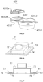
FIG. 6 is a schematic structural view of a cover plate; -
FIG. 7 is a cross-sectional view of the cover plate; -
FIG. 8 is a cross-sectional view taken along line X-X in a frame A ofFIG. 2 ; -
FIG. 9 is an enlarged schematic structural view of a portion in a circle C ofFIG. 8 ; -
FIG. 10 is an enlarged schematic structural view of a portion in a circle D ofFIG. 8 ; -
FIG. 11 is a cross-sectional view taken along line Y-Y in the frame A ofFIG. 2 ; -
FIG. 12 is an enlarged schematic structural view of a portion in a dashed-line box B ofFIG. 2 ; -
FIG. 13 is a schematic view of a back side of a door body; -
FIG. 14 is an enlarged schematic structural view of a portion in a circle E ofFIG. 13 . - In the
figures: 1 . door body; 11. first accommodation cavity; 12. second accommodation cavity; 121. opening; 1211. waterproof flange; 13. heating wire; 14. sealing ring; 15. first gap; 16. second gap; 2. refrigeration compartment; 3. lower air duct; 4. ice crushing bucket; 5. cutter head; 6. drive unit; 61. driving rod; 62. gear set; 621. first gear; 622. second gear; 623. connection box; 6231. first box body; 6232. second box body; 6232a. upper cover; 6232b. lower cover; 6233. side wall; 6233A. hollow portion; 63. motor; 7. cover plate; 71. cover plate body; 72. extension wall; 73. first waterproof block; 74. second waterproof block; 75. waterproof groove; 8. first water drain pipe; 9. ice outlet channel; 10. second water drain pipe; 11. third water drain pipe. - To make the objectives, technical solutions and advantages of the present invention clearer, technical solutions of the present application will be described below in conjunction with specific embodiments of the present application with reference to figures. Obviously, the described embodiments are partial embodiments of the present application other than all embodiments. All other embodiments obtained by those having ordinary skill in the art based on the embodiments of the present application without making any inventive efforts fall within the extent of protection of the present application.
- Embodiments of the present invention will be described in detail. Examples of the embodiments are shown in the figures, wherein the same or like reference signs always denote the same or similar elements or elements having the same or similar functions. The embodiments described hereunder with reference to figures are exemplary, and are only intended to illustrate the present invention, and cannot be construed as limiting the present invention.
- The terms "above", "below", "in", "out", and the like as used here, which denote spatial relative positions, describe the relationship of a component relative to another component in the accompanying drawings for the purpose of illustration. The terms of the spatial relative positions may be intended to comprise different orientations of the device in use or operation other than the orientations shown in the accompanying drawings. For example, the units that are described as being located "below" or "above" other units or features will be located "above" or "below" other units or features if the device in the accompanying drawings is turned upside down. Thus, the exemplary term "below" can encompass both two spatial orientations, namely, below and above.
- The device can be oriented in other ways (rotated by 90 degrees or other orientations), and the space-related descriptors used herein are explained accordingly. As in the present invention, for ease of description, when the refrigerator is in normal use, the direction toward the ground is downward, the direction away from the ground is upward, the direction parallel to the ground is a horizontal direction, and the direction perpendicular to the ground is a vertical direction.
- As shown in
FIG. 1 through FIG. 12 , an embodiment of the present invention provides an ice crushing device, which is disposed on adoor body 1 of the refrigerator. Thedoor body 1 is provided with afirst accommodation cavity 11 and asecond accommodation cavity 12 with anopening 121; the ice crushing device comprises: an ice crushing bucket 4 disposed in thefirst accommodation cavity 11, a cutter head 5 disposed in the ice crushing bucket 4, and a driving unit 6 at least partially disposed in thesecond accommodation cavity 12. The driving unit 6 comprises: a drivingrod 61 connected to the cutter head 5 and driving the cutter head 5 to rotate in the ice crushing bucket 4, a gear set 62 connected to and acting on the drivingrod 61, and amotor 63 for driving the gear set 62 to operate; wherein an edge of thedoor body 1 is provided with aheating wire 13; the ice crushing device further comprises: acover plate 7 for closing theopening 121 of thesecond accommodation cavity 12 so that thesecond accommodation cavity 12 is formed as a closed space, and afirst drain pipe 8 communicating thesecond accommodation cavity 12 with the refrigeration compartment 2 of the refrigerator; thecover plate 7 is sealingly connected with theopening 121 by awaterproof flange 1211 and awaterproof groove 75 that fit with each other; one of end holes of thefirst drain pipe 8 is disposed at the bottom of thesecond accommodation cavity 12, and the other of the end holes is exposed to the refrigeration compartment 2 and disposed close to theheating wire 13. - Specifically, the
door body 1 of the refrigerator is provided with afirst accommodation cavity 11 and asecond accommodation cavity 12; thesecond accommodation cavity 12 is located below thefirst accommodation cavity 11 and provided with anupward opening 121. Thefirst accommodation cavity 11 is communicated with thesecond accommodation cavity 12 through theopening 121, and the two accommodation cavities are located in an upper half of thedoor body 1 to facilitate the user to stand and use the crushed ice prepared the refrigerator. The edge of thedoor body 1 is also provided with aheating wire 13, theheating wire 13 extends along the periphery of thefirst accommodation cavity 11, and theheating wire 13 can prevent condensation. - The ice crushing device comprises an ice crushing bucket 4, a cutter head 5, and a driving unit 6. The driving unit 6 comprises a driving
rod 61, a gear set 62 and amotor 63; the ice crushing bucket 4 is located in thefirst accommodation cavity 11, and the cutter head 5 is disposed in the ice crushing bucket 4; themotor 63 is placed in thesecond accommodation cavity 12 with an output shaft vertically upward, the output shaft of themotor 63 is connected to and drives the gear set 62 to operate, the gear set 62 is connected to and drives the drivingrod 61 to rotate, the drivingrod 61 is connected to the cutter head 5 and drives the cutter head 5 to rotate in the ice crushing bucket 4, thereby realizing ice crushing. - The ice crushing device further comprises a
cover plate 7 and afirst drain pipe 8; thecover plate 7 is provided with awaterproof groove 75, theopening 121 of thesecond accommodation cavity 12 is provided with awaterproof flange 1211, thewaterproof flange 1211 and thewaterproof groove 75 engage with each other to sealingly connect thecover plate 7 with theopening 121, thereby forming a closed space in thesecond accommodation cavity 12 to prevent water and ice slag from entering thesecond accommodation cavity 12 to affect normal operation of themotor 63; one of end holes of thefirst drain pipe 8 is disposed at the bottom of thesecond accommodation cavity 12, and the other of the end holes is exposed to the refrigeration compartment 2 and close to theheating wire 13, thereby communicating thesecond accommodation cavity 12 with the refrigeration compartment 2 of the refrigerator, to drain the accumulated water inside thesecond accommodation cavity 12 and prevent the accumulated water from affecting themotor 63 and causing damages. - Further, the gear set 62 comprises: a
first gear 621 sleeved on an outer circumference of the ice crushing bucket 4, and asecond gear 622 that meshes with thefirst gear 621 to indirectly drive the cutter head 5 to rotate; wherein thefirst gear 621 is disposed at an upper end of the ice crushing bucket 4 and coaxial with the drivingrod 61, a central axis of thesecond gear 622 is parallel to the drivingrod 61, and themotor 63 drives thesecond gear 622 to rotate. - As shown in
FIG. 3 and FIG. 4 , the gear set 62 comprises thefirst gear 621 and thesecond gear 622; thefirst gear 621 is sleeved on an upper end of the outer circumference of the ice crushing bucket 4 and is coaxial with the drivingrod 61, and thesecond gear 622 and thefirst gear 621 mesh with each other and the central axis of thesecond gear 622 is parallel to the drivingrod 61. When themotor 63 is connected to and drives thesecond gear 622 to rotate, thesecond gear 622 indirectly drives the cutter head 5 to rotate via thefirst gear 621 and the ice crushing bucket 4, thereby performing the ice crushing function. - Preferably, the
first gear 621 and thesecond gear 622 may be configured as spur gears. By improving the transmission manner with two bevel gears in the prior art, themotor 63 is mounted below the ice crushing bucket 4, and the direct transmission through the spur gears may greatly improve the transmission efficiency of themotor 63 and reduce the transmission loss. - Furthermore, the gear set 62 further comprises: a
connection box 623 fixedly disposed in thefirst accommodation cavity 11, and theconnection box 623 comprises: afirst box body 6231 receiving thefirst gear 621 and asecond box body 6232 receiving thesecond gear 622 and connected to thefirst box body 6231; thefirst box body 6231 and thesecond box body 6232 share aside wall 6233, and theside wall 6233 is at least partially hollowed out to form ahollow portion 6233A, and thefirst gear 621 and thesecond gear 622 are in meshing connection with each other through thehollow portion 6233A. - Furthermore, the
second box body 6232 comprises anupper cover 6232a and alower cover 6232b that are detachably provided with each other. An upper edge of thelower cover 6232b is disposed lower than the upper edge of thefirst box body 6231, and thesecond gear 622 is disposed in the accommodation cavity formed between theupper cover 6232a and thelower cover 6232b. - As shown in
FIG. 5 , the gear set 62 further comprises aconnection box 623 which is fixedly disposed in thefirst accommodation cavity 11; theconnection box 623 comprises afirst box body 6231 and asecond box body 6232; thefirst box body 6231 is received in thefirst gear 621, and thesecond box body 6232 is received in thesecond gear 622; thefirst box body 6231 and thesecond box body 6232 share aside wall 6233 for fixed connection, and a portion of theside wall 6233 is hollowed out to form ahollow portion 6233A, and thefirst gear 621 and thesecond gear 622 are in meshing connection with each other in a space where thehollow portion 6233A is located. - The
second box body 6232 further comprises aupper cover 6232a and alower cover 6232b which are detachably disposed; thesecond gear 622 is disposed in the accommodation cavity formed after theupper cover 6232a and thelower cover 6232b are sealingly connected; an upper edge of thelower cover 6232b is lower than an upper edge of thefirst box body 6231; after theupper cover 6232a and thelower cover 6232b are connected, theupper cover 6232a abuts against theside wall 6233, which may ensure the sealing performance of the connection between theupper cover 6232a and thelower cover 6232b and effectively prevent adhesion of the gears as ice slag falls into the gap between the gears. - Further, an upper end edge of the
opening 121 constitutes awaterproof flange 1211; thecover plate 7 comprises: acover plate body 71, anextension wall 72 extending from the edge of thecover plate body 71 perpendicularly towards the opening 121, a firstwaterproof block 73 disposed extending from theextension wall 72 away from the end of thecover plate body 71, and a secondwaterproof block 74 disposed on an end face of the firstwaterproof block 73 away from theopening 121; awaterproof groove 75 is provided in a portion shared by the firstwaterproof block 73 and secondwaterproof block 74, and provided on an end face of the firstwaterproof block 73 towards the opening 121; a depth of thewaterproof groove 75 is not smaller than a height of the firstwaterproof block 73. - Specifically, the upper end edge of the
opening 121 protrudes vertically upwards to form a closedwaterproof flange 1211. The downward side of thecover plate 7 is provided with thewaterproof groove 75, and thewaterproof flange 1211 is hermetically connected with thewaterproof groove 75. - As shown in
FIG. 6 and FIG. 7 , thecover 7 comprises acover plate body 71, anextension wall 72, a firstwaterproof block 73 and a secondwaterproof block 74; thecover plate body 71 is disposed in a horizontal direction, the edge of thecover plate body 71 extends vertically downward to form theextension wall 72, the edge of theextension wall 72 extends horizontally outward to form the firstwaterproof block 73, and the secondwaterproof block 74 is stacked on top of the firstwaterproof block 73; thewaterproof groove 75 is provided in an overlapping region of the firstwaterproof block 73 and the secondwaterproof block 74 and opens downward, and the depth of thewaterproof groove 75 is not smaller than the height of the firstwaterproof block 73. - It can be seen that the
cover plate 7 can not only shield themotor 63 to prevent ice slag from falling into themotor 63, but also effectively block the accumulated water outside thewaterproof flange 1211 to prevent the accumulated water from flowing into thesecond accommodation cavity 12 and affecting themotor 63. - Furthermore, a sealing
ring 14 is provided on the peripheral side of thedoor body 1, theheating wire 13 is arranged around the sealingring 14 and at least partially forms afirst gap 15 with the sealingring 14, and the other end hole of thefirst drain pipe 8 is disposed in thefirst gap 15. - As shown in
FIG. 8 and FIG. 9 , thefirst accommodation cavity 11 is provided with a matching small door (not shown in the figures). The small door may close thefirst accommodation cavity 11 to seal it, thereby isolating a freezing space in thefirst accommodation cavity 11 from an external refrigeration space; the sealingring 14 extends along the periphery of the opening of thefirst accommodation cavity 11. After the small door is closed, the sealingring 14 abuts against the small door to ensure the sealing performance of the small door relative to thefirst accommodation cavity 11 and prevent the circulation of the cold air. Theheating wire 13 is disposed around the outer periphery of the sealingring 14 and forms several gaps with the sealingring 14. The end hole of thefirst drain pipe 8 is disposed in thefirst gap 15, i.e., the end hole of thefirst drain pipe 8 is disposed between the sealingring 14 theheating wire 13, thereby effectively suppressing occurrence of condensation in thefirst drain pipe 8. - Preferably, the
heating wire 13 surrounds the end hole of thefirst drain pipe 8 in an arcuate shape, which may expand the heated area and greatly suppress the condensation phenomenon. - Furthermore, the ice crushing device further comprises an ice outlet channel 9 communicating the ice crushing bucket 4 with the outside of the
door body 1; asecond drain pipe 10 communicated with the ice outlet channel 9 is provided on theside wall 6233 of the ice outlet channel 9, and the other end hole of thesecond drain pipe 10 is exposed to the refrigeration compartment 2 and disposed close to theheating wire 13. - Furthermore, the
heating wire 13 and the sealingring 14 further form asecond gap 16, and the other end hole of thesecond drain pipe 10 is disposed in thesecond gap 16. - As shown in
FIG. 11 andFIG. 12 , the ice crushing device further comprises an ice outlet channel 9, the ice outlet channel 9 communicates the ice crushing bucket 4 with the outside of thedoor body 1 and transports ice cubes to the outside of the refrigerator to facilitate the user to use ice; asecond drain pipe 10 is provided on theside wall 6233 of the ice outlet channel 9, and the other end hole of thesecond drain pipe 10 is also exposed to the refrigeration compartment 2 and close to theheating wire 13, i.e., located in thesecond gap 16 formed by theheating wire 13 and the sealingring 14. - Therefore, when an abnormal water fill process of the ice maker of the refrigerator causes continuous water fill or large water accumulation in the ice crushing bucket 4, since the
first accommodation cavity 11 is sealed by the small door and the sealingring 14 and the ice outlet channel 9 is sealed by an ice outlet cover plate (not shown), water will accumulate in the ice outlet channel 9 and spread to thefirst accommodation cavity 11. At this time, thesecond drain pipe 10 may drain the accumulated water to prevent the accumulated water from entering thefirst accommodation cavity 11 to cause damages to themotor 63, and also prevent the accumulated water from flowing to the cabinet along the air duct of the refrigerator, thereby causing damages to the evaporator in the cabinet, after the water level rises. - Preferably, the
second drain pipe 10 is disposed at the top of the ice outlet channel 9 to quickly discharge the accumulated water spreading into thefirst accommodation cavity 11 in time. - Further, a
third drain pipe 11 communicated with thefirst accommodation cavity 11 is provided at the bottom of thefirst accommodation cavity 11, and the other end hole of thethird drain pipe 11 is exposed to thelower air duct 3 on thedoor body 1. - As shown in
FIG. 13 andFIG. 14 , the bottom of thefirst accommodation cavity 11 is also provided with thethird drain pipe 11 which communicates thefirst accommodation cavity 11 with thelower air duct 3 disposed on thedoor body 1 of the refrigerator, thereby further draining the water accumulated in thefirst accommodation cavity 11 and preventing the damages caused by the accumulated water entering the evaporator. - In order to achieve one of the above-mentioned objects of the present invention, the present invention further provides a refrigerator comprising a
door body 1 and the ice crushing device which is dispose on thedoor body 1 so that the user can conveniently take ice from the outside of thedoor body 1. - To conclude, in the ice crushing device and the refrigerator having the same according to the present invention, the transmission mode of the
motor 63 is improved, thecover plate 7 prevents ice slag and water from entering themotor 63 and affecting themotor 63 in the ice crushing process, and meanwhile a plurality of water drain pipes are provided to drain the possible accumulated water as soon as possible in time, thereby solving problems with the conventional refrigerator that the ice maker has a low transmission efficiency, the crushed ice is prone to cause adhesion of gears, and the accumulated water is apt to cause damages to themotor 63 and evaporator, and thereby improving the convenience in using the refrigerator. - It should be understood that although the description is described according to the embodiments, not every embodiment only comprises one independent technical solution, that such a description manner is only for the sake of clarity, that those skilled in the art should take the description as an integral part, and that the technical solutions in the embodiments may be suitably combined to form other embodiments understandable by those skilled in the art.
- The detailed descriptions set forth above are merely specific illustrations of feasible embodiments of the present invention, and are not intended to limit the scope of protection of the present invention. All equivalent embodiments or modifications that do not depart from the art spirit of the present invention should fall within the scope of protection of the present invention.
Claims (10)
- An ice crushing device disposed on a door body of a refrigerator, wherein the door body is provided with a first accommodation cavity and a second accommodation cavity with an opening;the ice crushing device comprises: an ice crushing bucket disposed in the first accommodation cavity, a cutter head disposed in the ice crushing bucket, and a driving unit at least partially disposed in the second accommodation cavity, the driving unit comprising: a driving rod connected to the cutter head and driving the cutter head to rotate in the ice crushing bucket, a gear set connected to and acting on the driving rod, and a motor for driving the gear set to operate;wherein an edge of the door body is provided with a heating wire;the ice crushing device further comprises: a cover plate for closing the opening of the second accommodation cavity so that the second accommodation cavity is formed as a closed space, and a first drain pipe communicating the second accommodation cavity with a refrigeration compartment of the refrigerator;the cover plate is sealingly connected with the opening by a waterproof flange and a waterproof groove that fit with each other;one of end holes of the first drain pipe is disposed at a bottom of the second accommodation cavity, and the other of the end holes is exposed to the refrigeration compartment and disposed close to the heating wire.
- The ice crushing device according to claim 1, wherein the gear set comprises:a first gear sleeved on an outer circumference of the ice crushing bucket, and a second gear that meshes with the first gear to indirectly drive the cutter head to rotate;wherein the first gear is disposed at an upper end of the ice crushing bucket and coaxial with the driving rod, a central axis of the second gear is parallel to the driving rod, and the motor drives the second gear to rotate.
- The ice crushing device according to claim 2, wherein the gear set further comprises:a connection box fixedly disposed in the first accommodation cavity, the connection box comprising: a first box body receiving the first gear, and a second box body receiving the second gear and connected to the first box body;the first box body and the second box body share a side wall, and the side wall is at least partially hollowed out to form a hollow portion, and the first gear and the second gear are in meshing connection with each other through the hollow portion.
- The ice crushing device according to claim 3, wherein the second box body comprises an upper cover and a lower cover that are detachably provided with each other, an upper edge of the lower cover is disposed lower than an upper edge of the first box body, and the second gear is disposed in the accommodation cavity formed between the upper cover and the lower cover.
- The ice crushing device according to claim 1, wherein an upper end edge of the opening constitutes the waterproof flange;the cover plate comprises: a cover plate body, an extension wall extending from the edge of the cover plate body perpendicularly towards the opening, a first waterproof block disposed extending from the extension wall away from the end of the cover plate body, and a second waterproof block disposed on an end face of the first waterproof block away from the opening;the waterproof groove is provided in a portion shared by the first waterproof block and second waterproof block, and provided on an end face of the first waterproof block towards the opening;a depth of the waterproof groove is not smaller than a height of the first waterproof block.
- The ice crushing device according to claim 1, wherein a sealing ring is provided on a peripheral side of the door body, the heating wire is arranged around the sealing ring and at least partially forms a first gap with the sealing ring, and the other end hole of the first drain pipe is disposed in the first gap.
- The ice crushing device according to claim 6, wherein the ice crushing device further comprises an ice outlet channel communicating the ice crushing bucket with the outside of the door body;
a second drain pipe communicated with the ice outlet channel is provided on the side wall of the ice outlet channel, and the other end hole of the second drain pipe is exposed to the refrigeration compartment and disposed close to the heating wire. - The ice crushing device according to claim 7, wherein the heating wire and the sealing ring further form a second gap, and the other end hole of the second drain pipe is disposed in the second gap.
- The ice crushing device according to claim 1, wherein a third drain pipe communicated with the first accommodation cavity is provided at the bottom of the first accommodation cavity, and the other end hole of the third drain pipe is exposed to a lower air duct on the door body.
- A refrigerator, wherein the refrigerator comprises a door body, and the ice crushing device according to claim 1, the ice crushing device being disposed on the door body.
Applications Claiming Priority (2)
| Application Number | Priority Date | Filing Date | Title |
|---|---|---|---|
| CN201910240518.5A CN111750585A (en) | 2019-03-28 | 2019-03-28 | Ice crushing device and refrigerator having the same |
| PCT/CN2019/105078 WO2020192028A1 (en) | 2019-03-28 | 2019-09-10 | Ice crushing device and refrigerator having same |
Publications (3)
| Publication Number | Publication Date |
|---|---|
| EP3951289A1 true EP3951289A1 (en) | 2022-02-09 |
| EP3951289A4 EP3951289A4 (en) | 2022-05-18 |
| EP3951289B1 EP3951289B1 (en) | 2024-03-13 |
Family
ID=72611217
Family Applications (1)
| Application Number | Title | Priority Date | Filing Date |
|---|---|---|---|
| EP19921143.4A Active EP3951289B1 (en) | 2019-03-28 | 2019-09-10 | Refrigerator |
Country Status (4)
| Country | Link |
|---|---|
| EP (1) | EP3951289B1 (en) |
| CN (1) | CN111750585A (en) |
| AU (1) | AU2019438321B2 (en) |
| WO (1) | WO2020192028A1 (en) |
Family Cites Families (14)
| Publication number | Priority date | Publication date | Assignee | Title |
|---|---|---|---|---|
| CA1281556C (en) * | 1987-07-20 | 1991-03-19 | John Michael Herbert | Apparatus for preparing frozen drinks |
| KR890004143A (en) * | 1987-08-21 | 1989-04-20 | 시키 모리야 | Ice container and freezer for ice making |
| CN2881470Y (en) * | 2005-02-01 | 2007-03-21 | 海尔集团公司 | Air direct cooling combined multi temperature controlling refrigerator equipped with ice making machine |
| JP5147545B2 (en) * | 2008-05-30 | 2013-02-20 | 日立アプライアンス株式会社 | refrigerator |
| US8201478B2 (en) * | 2009-04-29 | 2012-06-19 | Molon Motor And Coil Corp. | Gear box for ice dispenser |
| CN102183118A (en) * | 2011-03-28 | 2011-09-14 | 海尔集团公司 | Ice making system of refrigerator |
| US8826683B2 (en) * | 2011-10-31 | 2014-09-09 | General Electric Company | Ice dispenser with crusher for a refrigerator appliance |
| KR101907166B1 (en) * | 2011-12-30 | 2018-10-15 | 삼성전자주식회사 | Refrigerator |
| CN104329874A (en) * | 2014-11-11 | 2015-02-04 | 合肥华凌股份有限公司 | Draining-tank assembly for refrigerator and refrigerator |
| KR102565130B1 (en) * | 2016-06-08 | 2023-08-09 | 코웨이 주식회사 | Ice storage tank |
| CN107014127A (en) * | 2017-05-05 | 2017-08-04 | 青岛海尔股份有限公司 | A kind of ice breaker and chipper |
| CN108759217B (en) * | 2018-05-21 | 2021-04-23 | 海尔智家股份有限公司 | Ice crusher and refrigerator |
| CN108800694B (en) * | 2018-05-21 | 2021-03-23 | 海尔智家股份有限公司 | Ice crushing device and refrigerator |
| CN108759216B (en) * | 2018-05-21 | 2020-11-20 | 海尔智家股份有限公司 | Ice crusher and refrigerator |
-
2019
- 2019-03-28 CN CN201910240518.5A patent/CN111750585A/en active Pending
- 2019-09-10 EP EP19921143.4A patent/EP3951289B1/en active Active
- 2019-09-10 AU AU2019438321A patent/AU2019438321B2/en active Active
- 2019-09-10 WO PCT/CN2019/105078 patent/WO2020192028A1/en not_active Ceased
Also Published As
| Publication number | Publication date |
|---|---|
| EP3951289B1 (en) | 2024-03-13 |
| CN111750585A (en) | 2020-10-09 |
| AU2019438321A1 (en) | 2021-10-14 |
| WO2020192028A1 (en) | 2020-10-01 |
| EP3951289A4 (en) | 2022-05-18 |
| AU2019438321B2 (en) | 2022-12-15 |
Similar Documents
| Publication | Publication Date | Title |
|---|---|---|
| KR20180057717A (en) | Refrigerator | |
| KR20180054874A (en) | Refrigerator | |
| KR20180053415A (en) | Refrigerator | |
| US20210018243A1 (en) | Ice crushing device and refrigerator | |
| KR20120007202A (en) | Refrigerator | |
| US11448444B2 (en) | Ice crushing device and refrigerator | |
| US11448443B2 (en) | Ice crushing device and refrigerator | |
| US11448442B2 (en) | Ice crushing device and refrigerator | |
| US11448445B2 (en) | Ice crushing device and refrigerator | |
| US20160201965A1 (en) | Ice makers and refrigeration appliances with ice makers | |
| US9404683B2 (en) | Refrigerator appliance | |
| MX2007016414A (en) | Ice making and storing system. | |
| US20190264974A1 (en) | Refrigerator appliance | |
| AU2019438321B2 (en) | Ice crushing device and refrigerator having same | |
| EP3967954B1 (en) | Ice maker and refrigerator | |
| EP3978839A1 (en) | Adjustable ice crusher | |
| KR20110072393A (en) | Refrigerator | |
| EP3037748B1 (en) | Refrigerator | |
| US20190360741A1 (en) | Refrigerator appliance with multiple zone flexible chamber in door | |
| CN105783371A (en) | Refrigerator | |
| KR20110072436A (en) | Refrigerator | |
| CN115406159B (en) | Refrigerator with ice maker | |
| EP3896370A1 (en) | Refrigerator | |
| CN103471313A (en) | Refrigerator | |
| CN217383436U (en) | Waterproof shell with good sealing effect |
Legal Events
| Date | Code | Title | Description |
|---|---|---|---|
| STAA | Information on the status of an ep patent application or granted ep patent |
Free format text: STATUS: THE INTERNATIONAL PUBLICATION HAS BEEN MADE |
|
| PUAI | Public reference made under article 153(3) epc to a published international application that has entered the european phase |
Free format text: ORIGINAL CODE: 0009012 |
|
| STAA | Information on the status of an ep patent application or granted ep patent |
Free format text: STATUS: REQUEST FOR EXAMINATION WAS MADE |
|
| 17P | Request for examination filed |
Effective date: 20210928 |
|
| AK | Designated contracting states |
Kind code of ref document: A1 Designated state(s): AL AT BE BG CH CY CZ DE DK EE ES FI FR GB GR HR HU IE IS IT LI LT LU LV MC MK MT NL NO PL PT RO RS SE SI SK SM TR |
|
| A4 | Supplementary search report drawn up and despatched |
Effective date: 20220420 |
|
| RIC1 | Information provided on ipc code assigned before grant |
Ipc: F25D 23/02 20060101ALN20220412BHEP Ipc: F25D 21/14 20060101ALI20220412BHEP Ipc: F25D 21/04 20060101ALI20220412BHEP Ipc: F25C 5/04 20060101AFI20220412BHEP |
|
| DAV | Request for validation of the european patent (deleted) | ||
| DAX | Request for extension of the european patent (deleted) | ||
| GRAP | Despatch of communication of intention to grant a patent |
Free format text: ORIGINAL CODE: EPIDOSNIGR1 |
|
| STAA | Information on the status of an ep patent application or granted ep patent |
Free format text: STATUS: GRANT OF PATENT IS INTENDED |
|
| RIC1 | Information provided on ipc code assigned before grant |
Ipc: F25D 23/02 20060101ALN20231121BHEP Ipc: F25C 5/20 20180101ALI20231121BHEP Ipc: F25D 21/14 20060101ALI20231121BHEP Ipc: F25D 21/04 20060101ALI20231121BHEP Ipc: F25C 5/04 20060101AFI20231121BHEP |
|
| INTG | Intention to grant announced |
Effective date: 20231206 |
|
| GRAS | Grant fee paid |
Free format text: ORIGINAL CODE: EPIDOSNIGR3 |
|
| GRAA | (expected) grant |
Free format text: ORIGINAL CODE: 0009210 |
|
| STAA | Information on the status of an ep patent application or granted ep patent |
Free format text: STATUS: THE PATENT HAS BEEN GRANTED |
|
| AK | Designated contracting states |
Kind code of ref document: B1 Designated state(s): AL AT BE BG CH CY CZ DE DK EE ES FI FR GB GR HR HU IE IS IT LI LT LU LV MC MK MT NL NO PL PT RO RS SE SI SK SM TR |
|
| REG | Reference to a national code |
Ref country code: GB Ref legal event code: FG4D |
|
| REG | Reference to a national code |
Ref country code: CH Ref legal event code: EP |
|
| REG | Reference to a national code |
Ref country code: DE Ref legal event code: R096 Ref document number: 602019048440 Country of ref document: DE |
|
| REG | Reference to a national code |
Ref country code: IE Ref legal event code: FG4D |
|
| PG25 | Lapsed in a contracting state [announced via postgrant information from national office to epo] |
Ref country code: LT Free format text: LAPSE BECAUSE OF FAILURE TO SUBMIT A TRANSLATION OF THE DESCRIPTION OR TO PAY THE FEE WITHIN THE PRESCRIBED TIME-LIMIT Effective date: 20240313 |
|
| REG | Reference to a national code |
Ref country code: LT Ref legal event code: MG9D |
|
| PG25 | Lapsed in a contracting state [announced via postgrant information from national office to epo] |
Ref country code: GR Free format text: LAPSE BECAUSE OF FAILURE TO SUBMIT A TRANSLATION OF THE DESCRIPTION OR TO PAY THE FEE WITHIN THE PRESCRIBED TIME-LIMIT Effective date: 20240614 |
|
| REG | Reference to a national code |
Ref country code: NL Ref legal event code: MP Effective date: 20240313 |
|
| PG25 | Lapsed in a contracting state [announced via postgrant information from national office to epo] |
Ref country code: HR Free format text: LAPSE BECAUSE OF FAILURE TO SUBMIT A TRANSLATION OF THE DESCRIPTION OR TO PAY THE FEE WITHIN THE PRESCRIBED TIME-LIMIT Effective date: 20240313 Ref country code: RS Free format text: LAPSE BECAUSE OF FAILURE TO SUBMIT A TRANSLATION OF THE DESCRIPTION OR TO PAY THE FEE WITHIN THE PRESCRIBED TIME-LIMIT Effective date: 20240613 |
|
| PG25 | Lapsed in a contracting state [announced via postgrant information from national office to epo] |
Ref country code: ES Free format text: LAPSE BECAUSE OF FAILURE TO SUBMIT A TRANSLATION OF THE DESCRIPTION OR TO PAY THE FEE WITHIN THE PRESCRIBED TIME-LIMIT Effective date: 20240313 |
|
| PG25 | Lapsed in a contracting state [announced via postgrant information from national office to epo] |
Ref country code: RS Free format text: LAPSE BECAUSE OF FAILURE TO SUBMIT A TRANSLATION OF THE DESCRIPTION OR TO PAY THE FEE WITHIN THE PRESCRIBED TIME-LIMIT Effective date: 20240613 Ref country code: NO Free format text: LAPSE BECAUSE OF FAILURE TO SUBMIT A TRANSLATION OF THE DESCRIPTION OR TO PAY THE FEE WITHIN THE PRESCRIBED TIME-LIMIT Effective date: 20240613 Ref country code: LT Free format text: LAPSE BECAUSE OF FAILURE TO SUBMIT A TRANSLATION OF THE DESCRIPTION OR TO PAY THE FEE WITHIN THE PRESCRIBED TIME-LIMIT Effective date: 20240313 Ref country code: HR Free format text: LAPSE BECAUSE OF FAILURE TO SUBMIT A TRANSLATION OF THE DESCRIPTION OR TO PAY THE FEE WITHIN THE PRESCRIBED TIME-LIMIT Effective date: 20240313 Ref country code: GR Free format text: LAPSE BECAUSE OF FAILURE TO SUBMIT A TRANSLATION OF THE DESCRIPTION OR TO PAY THE FEE WITHIN THE PRESCRIBED TIME-LIMIT Effective date: 20240614 Ref country code: FI Free format text: LAPSE BECAUSE OF FAILURE TO SUBMIT A TRANSLATION OF THE DESCRIPTION OR TO PAY THE FEE WITHIN THE PRESCRIBED TIME-LIMIT Effective date: 20240313 Ref country code: ES Free format text: LAPSE BECAUSE OF FAILURE TO SUBMIT A TRANSLATION OF THE DESCRIPTION OR TO PAY THE FEE WITHIN THE PRESCRIBED TIME-LIMIT Effective date: 20240313 Ref country code: BG Free format text: LAPSE BECAUSE OF FAILURE TO SUBMIT A TRANSLATION OF THE DESCRIPTION OR TO PAY THE FEE WITHIN THE PRESCRIBED TIME-LIMIT Effective date: 20240313 |
|
| REG | Reference to a national code |
Ref country code: AT Ref legal event code: MK05 Ref document number: 1666103 Country of ref document: AT Kind code of ref document: T Effective date: 20240313 |
|
| PG25 | Lapsed in a contracting state [announced via postgrant information from national office to epo] |
Ref country code: SE Free format text: LAPSE BECAUSE OF FAILURE TO SUBMIT A TRANSLATION OF THE DESCRIPTION OR TO PAY THE FEE WITHIN THE PRESCRIBED TIME-LIMIT Effective date: 20240313 Ref country code: LV Free format text: LAPSE BECAUSE OF FAILURE TO SUBMIT A TRANSLATION OF THE DESCRIPTION OR TO PAY THE FEE WITHIN THE PRESCRIBED TIME-LIMIT Effective date: 20240313 |
|
| PG25 | Lapsed in a contracting state [announced via postgrant information from national office to epo] |
Ref country code: NL Free format text: LAPSE BECAUSE OF FAILURE TO SUBMIT A TRANSLATION OF THE DESCRIPTION OR TO PAY THE FEE WITHIN THE PRESCRIBED TIME-LIMIT Effective date: 20240313 |
|
| PG25 | Lapsed in a contracting state [announced via postgrant information from national office to epo] |
Ref country code: NL Free format text: LAPSE BECAUSE OF FAILURE TO SUBMIT A TRANSLATION OF THE DESCRIPTION OR TO PAY THE FEE WITHIN THE PRESCRIBED TIME-LIMIT Effective date: 20240313 |
|
| PG25 | Lapsed in a contracting state [announced via postgrant information from national office to epo] |
Ref country code: IS Free format text: LAPSE BECAUSE OF FAILURE TO SUBMIT A TRANSLATION OF THE DESCRIPTION OR TO PAY THE FEE WITHIN THE PRESCRIBED TIME-LIMIT Effective date: 20240713 |
|
| PG25 | Lapsed in a contracting state [announced via postgrant information from national office to epo] |
Ref country code: SM Free format text: LAPSE BECAUSE OF FAILURE TO SUBMIT A TRANSLATION OF THE DESCRIPTION OR TO PAY THE FEE WITHIN THE PRESCRIBED TIME-LIMIT Effective date: 20240313 Ref country code: PT Free format text: LAPSE BECAUSE OF FAILURE TO SUBMIT A TRANSLATION OF THE DESCRIPTION OR TO PAY THE FEE WITHIN THE PRESCRIBED TIME-LIMIT Effective date: 20240715 |
|
| PG25 | Lapsed in a contracting state [announced via postgrant information from national office to epo] |
Ref country code: EE Free format text: LAPSE BECAUSE OF FAILURE TO SUBMIT A TRANSLATION OF THE DESCRIPTION OR TO PAY THE FEE WITHIN THE PRESCRIBED TIME-LIMIT Effective date: 20240313 Ref country code: CZ Free format text: LAPSE BECAUSE OF FAILURE TO SUBMIT A TRANSLATION OF THE DESCRIPTION OR TO PAY THE FEE WITHIN THE PRESCRIBED TIME-LIMIT Effective date: 20240313 |
|
| PG25 | Lapsed in a contracting state [announced via postgrant information from national office to epo] |
Ref country code: AT Free format text: LAPSE BECAUSE OF FAILURE TO SUBMIT A TRANSLATION OF THE DESCRIPTION OR TO PAY THE FEE WITHIN THE PRESCRIBED TIME-LIMIT Effective date: 20240313 |
|
| PG25 | Lapsed in a contracting state [announced via postgrant information from national office to epo] |
Ref country code: PL Free format text: LAPSE BECAUSE OF FAILURE TO SUBMIT A TRANSLATION OF THE DESCRIPTION OR TO PAY THE FEE WITHIN THE PRESCRIBED TIME-LIMIT Effective date: 20240313 |
|
| PG25 | Lapsed in a contracting state [announced via postgrant information from national office to epo] |
Ref country code: SK Free format text: LAPSE BECAUSE OF FAILURE TO SUBMIT A TRANSLATION OF THE DESCRIPTION OR TO PAY THE FEE WITHIN THE PRESCRIBED TIME-LIMIT Effective date: 20240313 |
|
| PG25 | Lapsed in a contracting state [announced via postgrant information from national office to epo] |
Ref country code: SM Free format text: LAPSE BECAUSE OF FAILURE TO SUBMIT A TRANSLATION OF THE DESCRIPTION OR TO PAY THE FEE WITHIN THE PRESCRIBED TIME-LIMIT Effective date: 20240313 Ref country code: SK Free format text: LAPSE BECAUSE OF FAILURE TO SUBMIT A TRANSLATION OF THE DESCRIPTION OR TO PAY THE FEE WITHIN THE PRESCRIBED TIME-LIMIT Effective date: 20240313 Ref country code: RO Free format text: LAPSE BECAUSE OF FAILURE TO SUBMIT A TRANSLATION OF THE DESCRIPTION OR TO PAY THE FEE WITHIN THE PRESCRIBED TIME-LIMIT Effective date: 20240313 Ref country code: PT Free format text: LAPSE BECAUSE OF FAILURE TO SUBMIT A TRANSLATION OF THE DESCRIPTION OR TO PAY THE FEE WITHIN THE PRESCRIBED TIME-LIMIT Effective date: 20240715 Ref country code: PL Free format text: LAPSE BECAUSE OF FAILURE TO SUBMIT A TRANSLATION OF THE DESCRIPTION OR TO PAY THE FEE WITHIN THE PRESCRIBED TIME-LIMIT Effective date: 20240313 Ref country code: IS Free format text: LAPSE BECAUSE OF FAILURE TO SUBMIT A TRANSLATION OF THE DESCRIPTION OR TO PAY THE FEE WITHIN THE PRESCRIBED TIME-LIMIT Effective date: 20240713 Ref country code: EE Free format text: LAPSE BECAUSE OF FAILURE TO SUBMIT A TRANSLATION OF THE DESCRIPTION OR TO PAY THE FEE WITHIN THE PRESCRIBED TIME-LIMIT Effective date: 20240313 Ref country code: CZ Free format text: LAPSE BECAUSE OF FAILURE TO SUBMIT A TRANSLATION OF THE DESCRIPTION OR TO PAY THE FEE WITHIN THE PRESCRIBED TIME-LIMIT Effective date: 20240313 Ref country code: AT Free format text: LAPSE BECAUSE OF FAILURE TO SUBMIT A TRANSLATION OF THE DESCRIPTION OR TO PAY THE FEE WITHIN THE PRESCRIBED TIME-LIMIT Effective date: 20240313 |
|
| PG25 | Lapsed in a contracting state [announced via postgrant information from national office to epo] |
Ref country code: IT Free format text: LAPSE BECAUSE OF FAILURE TO SUBMIT A TRANSLATION OF THE DESCRIPTION OR TO PAY THE FEE WITHIN THE PRESCRIBED TIME-LIMIT Effective date: 20240313 |
|
| REG | Reference to a national code |
Ref country code: DE Ref legal event code: R097 Ref document number: 602019048440 Country of ref document: DE |
|
| PG25 | Lapsed in a contracting state [announced via postgrant information from national office to epo] |
Ref country code: IT Free format text: LAPSE BECAUSE OF FAILURE TO SUBMIT A TRANSLATION OF THE DESCRIPTION OR TO PAY THE FEE WITHIN THE PRESCRIBED TIME-LIMIT Effective date: 20240313 |
|
| PG25 | Lapsed in a contracting state [announced via postgrant information from national office to epo] |
Ref country code: DK Free format text: LAPSE BECAUSE OF FAILURE TO SUBMIT A TRANSLATION OF THE DESCRIPTION OR TO PAY THE FEE WITHIN THE PRESCRIBED TIME-LIMIT Effective date: 20240313 |
|
| PLBE | No opposition filed within time limit |
Free format text: ORIGINAL CODE: 0009261 |
|
| STAA | Information on the status of an ep patent application or granted ep patent |
Free format text: STATUS: NO OPPOSITION FILED WITHIN TIME LIMIT |
|
| PG25 | Lapsed in a contracting state [announced via postgrant information from national office to epo] |
Ref country code: DK Free format text: LAPSE BECAUSE OF FAILURE TO SUBMIT A TRANSLATION OF THE DESCRIPTION OR TO PAY THE FEE WITHIN THE PRESCRIBED TIME-LIMIT Effective date: 20240313 |
|
| 26N | No opposition filed |
Effective date: 20241216 |
|
| PG25 | Lapsed in a contracting state [announced via postgrant information from national office to epo] |
Ref country code: SI Free format text: LAPSE BECAUSE OF FAILURE TO SUBMIT A TRANSLATION OF THE DESCRIPTION OR TO PAY THE FEE WITHIN THE PRESCRIBED TIME-LIMIT Effective date: 20240313 Ref country code: MC Free format text: LAPSE BECAUSE OF FAILURE TO SUBMIT A TRANSLATION OF THE DESCRIPTION OR TO PAY THE FEE WITHIN THE PRESCRIBED TIME-LIMIT Effective date: 20240313 |
|
| REG | Reference to a national code |
Ref country code: CH Ref legal event code: PL |
|
| PG25 | Lapsed in a contracting state [announced via postgrant information from national office to epo] |
Ref country code: LU Free format text: LAPSE BECAUSE OF NON-PAYMENT OF DUE FEES Effective date: 20240910 |
|
| REG | Reference to a national code |
Ref country code: BE Ref legal event code: MM Effective date: 20240930 |
|
| PG25 | Lapsed in a contracting state [announced via postgrant information from national office to epo] |
Ref country code: BE Free format text: LAPSE BECAUSE OF NON-PAYMENT OF DUE FEES Effective date: 20240930 |
|
| PG25 | Lapsed in a contracting state [announced via postgrant information from national office to epo] |
Ref country code: CH Free format text: LAPSE BECAUSE OF NON-PAYMENT OF DUE FEES Effective date: 20240930 |
|
| PG25 | Lapsed in a contracting state [announced via postgrant information from national office to epo] |
Ref country code: IE Free format text: LAPSE BECAUSE OF NON-PAYMENT OF DUE FEES Effective date: 20240910 |
|
| PGFP | Annual fee paid to national office [announced via postgrant information from national office to epo] |
Ref country code: DE Payment date: 20250916 Year of fee payment: 7 |
|
| PGFP | Annual fee paid to national office [announced via postgrant information from national office to epo] |
Ref country code: GB Payment date: 20250919 Year of fee payment: 7 |
|
| PGFP | Annual fee paid to national office [announced via postgrant information from national office to epo] |
Ref country code: FR Payment date: 20250929 Year of fee payment: 7 |
|
| PG25 | Lapsed in a contracting state [announced via postgrant information from national office to epo] |
Ref country code: CY Free format text: LAPSE BECAUSE OF FAILURE TO SUBMIT A TRANSLATION OF THE DESCRIPTION OR TO PAY THE FEE WITHIN THE PRESCRIBED TIME-LIMIT; INVALID AB INITIO Effective date: 20190910 |
|
| PG25 | Lapsed in a contracting state [announced via postgrant information from national office to epo] |
Ref country code: HU Free format text: LAPSE BECAUSE OF FAILURE TO SUBMIT A TRANSLATION OF THE DESCRIPTION OR TO PAY THE FEE WITHIN THE PRESCRIBED TIME-LIMIT; INVALID AB INITIO Effective date: 20190910 |