EP3951185A1 - Vacuum pump, casing, and intake opening flange - Google Patents
Vacuum pump, casing, and intake opening flange Download PDFInfo
- Publication number
- EP3951185A1 EP3951185A1 EP20778192.3A EP20778192A EP3951185A1 EP 3951185 A1 EP3951185 A1 EP 3951185A1 EP 20778192 A EP20778192 A EP 20778192A EP 3951185 A1 EP3951185 A1 EP 3951185A1
- Authority
- EP
- European Patent Office
- Prior art keywords
- casing
- inlet port
- port flange
- vacuum pump
- flange
- Prior art date
- Legal status (The legal status is an assumption and is not a legal conclusion. Google has not performed a legal analysis and makes no representation as to the accuracy of the status listed.)
- Granted
Links
Images




Classifications
-
- F—MECHANICAL ENGINEERING; LIGHTING; HEATING; WEAPONS; BLASTING
- F04—POSITIVE - DISPLACEMENT MACHINES FOR LIQUIDS; PUMPS FOR LIQUIDS OR ELASTIC FLUIDS
- F04D—NON-POSITIVE-DISPLACEMENT PUMPS
- F04D29/00—Details, component parts, or accessories
- F04D29/40—Casings; Connections of working fluid
- F04D29/42—Casings; Connections of working fluid for radial or helico-centrifugal pumps
- F04D29/4206—Casings; Connections of working fluid for radial or helico-centrifugal pumps especially adapted for elastic fluid pumps
-
- F—MECHANICAL ENGINEERING; LIGHTING; HEATING; WEAPONS; BLASTING
- F04—POSITIVE - DISPLACEMENT MACHINES FOR LIQUIDS; PUMPS FOR LIQUIDS OR ELASTIC FLUIDS
- F04D—NON-POSITIVE-DISPLACEMENT PUMPS
- F04D19/00—Axial-flow pumps
- F04D19/02—Multi-stage pumps
- F04D19/04—Multi-stage pumps specially adapted to the production of a high vacuum, e.g. molecular pumps
- F04D19/042—Turbomolecular vacuum pumps
-
- F—MECHANICAL ENGINEERING; LIGHTING; HEATING; WEAPONS; BLASTING
- F04—POSITIVE - DISPLACEMENT MACHINES FOR LIQUIDS; PUMPS FOR LIQUIDS OR ELASTIC FLUIDS
- F04D—NON-POSITIVE-DISPLACEMENT PUMPS
- F04D19/00—Axial-flow pumps
- F04D19/02—Multi-stage pumps
- F04D19/04—Multi-stage pumps specially adapted to the production of a high vacuum, e.g. molecular pumps
-
- F—MECHANICAL ENGINEERING; LIGHTING; HEATING; WEAPONS; BLASTING
- F04—POSITIVE - DISPLACEMENT MACHINES FOR LIQUIDS; PUMPS FOR LIQUIDS OR ELASTIC FLUIDS
- F04D—NON-POSITIVE-DISPLACEMENT PUMPS
- F04D29/00—Details, component parts, or accessories
- F04D29/02—Selection of particular materials
- F04D29/023—Selection of particular materials especially adapted for elastic fluid pumps
-
- F—MECHANICAL ENGINEERING; LIGHTING; HEATING; WEAPONS; BLASTING
- F04—POSITIVE - DISPLACEMENT MACHINES FOR LIQUIDS; PUMPS FOR LIQUIDS OR ELASTIC FLUIDS
- F04D—NON-POSITIVE-DISPLACEMENT PUMPS
- F04D29/00—Details, component parts, or accessories
- F04D29/60—Mounting; Assembling; Disassembling
- F04D29/601—Mounting; Assembling; Disassembling specially adapted for elastic fluid pumps
-
- F—MECHANICAL ENGINEERING; LIGHTING; HEATING; WEAPONS; BLASTING
- F04—POSITIVE - DISPLACEMENT MACHINES FOR LIQUIDS; PUMPS FOR LIQUIDS OR ELASTIC FLUIDS
- F04D—NON-POSITIVE-DISPLACEMENT PUMPS
- F04D29/00—Details, component parts, or accessories
- F04D29/60—Mounting; Assembling; Disassembling
- F04D29/64—Mounting; Assembling; Disassembling of axial pumps
- F04D29/644—Mounting; Assembling; Disassembling of axial pumps especially adapted for elastic fluid pumps
-
- F—MECHANICAL ENGINEERING; LIGHTING; HEATING; WEAPONS; BLASTING
- F05—INDEXING SCHEMES RELATING TO ENGINES OR PUMPS IN VARIOUS SUBCLASSES OF CLASSES F01-F04
- F05D—INDEXING SCHEME FOR ASPECTS RELATING TO NON-POSITIVE-DISPLACEMENT MACHINES OR ENGINES, GAS-TURBINES OR JET-PROPULSION PLANTS
- F05D2300/00—Materials; Properties thereof
- F05D2300/10—Metals, alloys or intermetallic compounds
- F05D2300/12—Light metals
- F05D2300/121—Aluminium
-
- F—MECHANICAL ENGINEERING; LIGHTING; HEATING; WEAPONS; BLASTING
- F05—INDEXING SCHEMES RELATING TO ENGINES OR PUMPS IN VARIOUS SUBCLASSES OF CLASSES F01-F04
- F05D—INDEXING SCHEME FOR ASPECTS RELATING TO NON-POSITIVE-DISPLACEMENT MACHINES OR ENGINES, GAS-TURBINES OR JET-PROPULSION PLANTS
- F05D2300/00—Materials; Properties thereof
- F05D2300/10—Metals, alloys or intermetallic compounds
- F05D2300/17—Alloys
- F05D2300/171—Steel alloys
Definitions
- the present invention relates to a vacuum pump in which an outer cylinder and a flange that are components of the vacuum pump are separately constructed of different materials, a casing, and an inlet port flange.
- Molecular pumps such as turbo-molecular pumps and thread groove pumps are often used to exhaust semiconductor manufacturing apparatuses and used as vacuum containers of electron microscopes or the like which require a high vacuum.
- Such vacuum pumps are usually provided with a flange of a predetermined size and are configured to be fixed by bolts or the like to an outlet port-side flange (hereinafter, referred to as an apparatus-side flange) of a vacuum apparatus (hereinafter, referred to as an apparatus) that requires exhaust.
- the flange of the vacuum pump (hereinafter, the flange of the vacuum pump will be referred to as an inlet port flange) and the apparatus-side flange by fixing the inlet port flange and the apparatus-side flange to each other while sandwiching an O-ring therebetween.
- the vacuum pump is provided with a rotor which is rotatably supported and which is capable of being rotated at high speed by a motor and a stator which is fixed to an inside of a casing of the vacuum pump.
- a motor rotates at high speed
- an exhaust action is exhibited due to an interaction between the rotor and the stator. Due to the exhaust action, gas on the apparatus side is sucked from an inlet port of the vacuum pump and exhausted through an outlet port of the vacuum pump. A high-vacuum state inside the apparatus is realized in this manner.
- the vacuum pump exhausts gas in a molecular flow region (a region with a high degree of vacuum in which particles less frequently collide with each other).
- a molecular flow region a region with a high degree of vacuum in which particles less frequently collide with each other.
- the rotor is required to rotate at a high speed of around 30,000 rotations per minute.
- the casing (outer cylinder) 2 and the inlet port flange 200 are integrally formed as a single component.
- the casing (outer cylinder) 2 and the inlet port flange 200 are integrally formed as a single component.
- vacuum pumps in which both components are manufactured as separate components and subsequently integrated by welding.
- Stainless steel is used as the material of the components.
- An invention according to claim 1 provides a vacuum pump including: an inlet port flange to be coupled to an apparatus; a casing which functions as a housing for covering internal members; an outlet port; a base portion; and a rotating portion which is enclosed by and rotatably supported by the casing and the base portion, wherein the inlet port flange and the casing are formed as separate components, the casing is made of aluminum, and the inlet port flange and the casing are fastened to each other.
- An invention according to claim 3 provides a casing used in a vacuum pump including: an inlet port flange to be coupled to an apparatus; a casing which functions as a housing for covering internal members; an outlet port; a base portion; and a rotating portion which is enclosed by and rotatably supported by the casing and the base portion, wherein the casing is formed as a separate component from the inlet port flange, the casing is made of aluminum, and the casing can be fastened to the inlet port flange.
- An invention according to claim 6 provides the vacuum pump according to claim 5, wherein the projecting portion or the inlet port flange is provided with a release portion for absorbing fracture energy.
- an inlet port flange 100 and a casing (outer cylinder) 2 are separated from each other and constructed as different members.
- FIGS. 1 and 2 a preferred embodiment of the present invention will be described in detail with reference to FIGS. 1 and 2 .
- FIG. 1 is a diagram showing a schematic configuration example of the vacuum pump 1 according to the embodiment of the present invention and represents a sectional view in an axis direction of the vacuum pump 1.
- a diameter direction of a rotor blade will be described as a "radial (diameter or radius) direction" and a direction perpendicular to the diameter direction of the rotor blade will be described as an "axis direction (or an axial direction)”.
- a control apparatus that controls an operation of the vacuum pump 1 is connected via a dedicated line to an outer part of the housing of the vacuum pump 1.
- An inlet port 4 for introducing a gas into the vacuum pump 1 is formed in an end portion of the casing (outer cylinder) 2.
- the inlet port flange 100 which overhangs toward an outer peripheral side is formed on an end surface of the casing (outer cylinder) 2 on a side of the inlet port 4.
- a direction of the spiral groove formed on the thread groove exhaust element 20 is a direction toward the outlet port 6 when gas is transferred in the spiral groove in a rotation direction of the rotor 8.
- the inlet port flange 100 is made of stainless steel, and a bolt hole 600 through which a fastening bolt 800 (refer to FIG. 1 ) to be used to fasten the inlet port flange 100 to the casing (outer cylinder) 2 is to be passed is provided in plurality inside the inlet port flange 100.
- a bolt hole 500 to be used when fastening the vacuum pump 1 to a vacuum apparatus is provided in plurality on an outer side of the bolt holes 600. The vacuum apparatus and the vacuum pump 1 are fastened to each other by bolts via the bolt holes 500.
- a projecting portion 900 to be used to perform positioning when fastening the casing (outer cylinder) 2 to the inlet port flange is provided across an entire periphery of the casing (outer cylinder) 2. Details of the projecting portion 900 will be given in the description of a second embodiment to be provided later.
- the casing (outer cylinder) 2 may be used in a corrosive gas environment
- the inside of the casing (outer cylinder) 2 is preferably subjected to an electroless Nip plating treatment.
- the inlet port flange 100 and the casing (outer cylinder) 2 are fastened to each other by the fastening bolts 800 via the respective bolt holes 600 and 700.
- the fastening bolts 800 are fastened to each other by the fastening bolts 800 via the respective bolt holes 600 and 700.
- airtightness is retained by an O-ring seal.
- the projecting portion 900 is provided across an entire periphery of the casing (outer cylinder) 2 on the assumption of the first embodiment that the casing (outer cylinder) 2 and the inlet port flange 100 are to be constructed as separate components.
- the projecting portion 900 is engaged with the inlet port flange 100 to perform positioning in a radius direction.
- FIG. 3 is a partial enlarged view of FIG. 1 (a portion enclosed by a dotted line).
- a gap between the two components in the radius direction is as small as possible.
- the projecting portion 900 deforms and consumes the fracture energy.
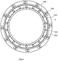
- FIG. 4 shows an example in which a plurality of (18) bow-shaped release portions 920 are provided on a surface of the projecting portion 900 that comes into contact with the inlet port flange 100 (denoted by ⁇ x in FIG. 3 ).
- the release portions 920 are arranged at regular intervals in a peripheral direction of the projecting portion 900.
- FIG. 5 is a partial enlarged view of FIG. 4 .
- a certain amount of fracture energy (F, refer to FIG. 3 ) received by the projecting portion 900 is absorbed.
- F fracture energy
- an amount of deformation (distortion) of the projecting portion 900 is enlarged to increase energy absorption efficiency of the projecting portion 900 due to plastic deformation and elastic deformation thereof.
- Adopting such a structure in which gaps are partially provided in the peripheral direction enables positioning in the radius direction to be performed, reduces impact to the inlet port flange 100 as compared to a structure without the gaps, and prevents breakage of the fastening bolts 800.
- release portions 920 shown in FIGS. 4 and 5 have bow shapes, alternatively, other shapes such as a C-shape that enable energy to be absorbed by the plastic deformation and the elastic deformation of the projecting portion 900 may be adopted.
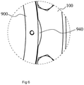
- a release portion is provided on a side of the inlet port flange 100 (an inlet port flange-side release portion 940).
- a shape of the inlet port flange-side release portion 940 is not limited to a bow shape and, for example, a C-shape may be adopted.
Landscapes
- Engineering & Computer Science (AREA)
- Mechanical Engineering (AREA)
- General Engineering & Computer Science (AREA)
- Non-Positive Displacement Air Blowers (AREA)
Abstract
Description
- The present invention relates to a vacuum pump in which an outer cylinder and a flange that are components of the vacuum pump are separately constructed of different materials, a casing, and an inlet port flange.
- Molecular pumps (vacuum pumps) such as turbo-molecular pumps and thread groove pumps are often used to exhaust semiconductor manufacturing apparatuses and used as vacuum containers of electron microscopes or the like which require a high vacuum.
- Such vacuum pumps are usually provided with a flange of a predetermined size and are configured to be fixed by bolts or the like to an outlet port-side flange (hereinafter, referred to as an apparatus-side flange) of a vacuum apparatus (hereinafter, referred to as an apparatus) that requires exhaust.
- High airtightness is maintained between the flange of the vacuum pump (hereinafter, the flange of the vacuum pump will be referred to as an inlet port flange) and the apparatus-side flange by fixing the inlet port flange and the apparatus-side flange to each other while sandwiching an O-ring therebetween.
- The vacuum pump is provided with a rotor which is rotatably supported and which is capable of being rotated at high speed by a motor and a stator which is fixed to an inside of a casing of the vacuum pump. When the motor rotates at high speed, an exhaust action is exhibited due to an interaction between the rotor and the stator. Due to the exhaust action, gas on the apparatus side is sucked from an inlet port of the vacuum pump and exhausted through an outlet port of the vacuum pump. A high-vacuum state inside the apparatus is realized in this manner.
- Usually, the vacuum pump exhausts gas in a molecular flow region (a region with a high degree of vacuum in which particles less frequently collide with each other). In order to exhibit exhaust performance in the molecular flow region, the rotor is required to rotate at a high speed of around 30,000 rotations per minute.
-
FIG. 7 is a diagram for describing a vacuum pump according to conventional art. As shown in the diagram, an outer side of avacuum pump 1 is formed by a casing (outer cylinder) 2, aninlet port flange 200, and a base 3. - Among these components, the casing (outer cylinder) 2 and the
inlet port flange 200 are integrally formed as a single component. There are other vacuum pumps in which both components are manufactured as separate components and subsequently integrated by welding. Stainless steel is used as the material of the components. - When using a component created by integrally forming the casing (outer cylinder) 2 and the
inlet port flange 200 as a single component using stainless steel, a high material cost results in high overall cost. In addition, processing such as machining requires great care. - On the other hand, when using components that are manufactured as separate components and subsequently integrated by welding, the welding operation requires great care, and despite no longer having to perform processing such as machining, cost reduction cannot be achieved.
- In addition, using stainless steel in the casing (outer cylinder) 2 increases weight and imposes a strain during installation work at an installation site.
- A vacuum pump and a flange disclosed in
Japanese Patent Application Laid-open No. 2008-75489 Japanese Patent Application Laid-open No. 2008-75489 -
Japanese Patent Application Laid-open No. 2015-59426 - 2d/D ≤ smax (D: outer diameter of stator component, d: width of gap, and smax: elongation at break of stator component)
- Accordingly, when fracture energy is generated, since the elongated and deformed stator component either does not come into contact or only comes into slight contact with the inner peripheral surface of the casing, the fracture energy can be prevented from being transferred to the casing via the stator component.
- In a vacuum pump, since a rotor is rotating at high speed inside the vacuum pump, when some kind of problem occurs during an operation of the vacuum pump and the rotor collides with a stator member inside the vacuum pump, a large torque that causes the entire vacuum pump to rotate in a direction of rotation of the rotor is instantaneously generated. The torque also places heavy stress on a vacuum container via the inlet port flange. Therefore, the inlet port flange may sometimes be provided with a buffer structure for reducing the torque such as that described in
Japanese Patent Application Laid-open No. 2008-75489 - On the other hand, there are demands for making the vacuum pump itself light weight in order to reduce strain during installation work on an installation site or the like.
- In addition, a technique is desired for absorbing, as much as possible, fracture energy created when the rotor breaks during rotation by a casing to prevent the fracture energy from affecting the inlet port flange of the vacuum pump.
- In consideration thereof, a first object of the present invention is to provide a vacuum pump which separates and constructs an inlet port flange and a casing (outer cylinder) as two components to reduce weight while retaining required strength and which is consequently capable of reducing manufacturing cost.
- In addition, a second object of the present invention is to provide a vacuum pump which, on the premise of separating and constructing an inlet port flange and a casing (outer cylinder) as two components, absorbs fracture energy with the casing as much as possible and prevents the inlet port flange of the vacuum pump from being affected.
- An invention according to
claim 1 provides a vacuum pump including: an inlet port flange to be coupled to an apparatus; a casing which functions as a housing for covering internal members; an outlet port; a base portion; and a rotating portion which is enclosed by and rotatably supported by the casing and the base portion, wherein the inlet port flange and the casing are formed as separate components, the casing is made of aluminum, and the inlet port flange and the casing are fastened to each other. - An invention according to
claim 2 provides the vacuum pump according toclaim 1, wherein the inlet port flange is made of stainless steel. - An invention according to claim 3 provides a casing used in a vacuum pump including: an inlet port flange to be coupled to an apparatus; a casing which functions as a housing for covering internal members; an outlet port; a base portion; and a rotating portion which is enclosed by and rotatably supported by the casing and the base portion, wherein the casing is formed as a separate component from the inlet port flange, the casing is made of aluminum, and the casing can be fastened to the inlet port flange.
- An invention according to claim 4 provides an inlet port flange used in a vacuum pump including: an inlet port flange to be coupled to an apparatus; a casing which functions as a housing for covering internal members; an outlet port; a base portion; and a rotating portion which is enclosed by and rotatably supported by the casing and the base portion, wherein the inlet port flange is formed as a separate component from the casing, the inlet port flange is made of stainless steel, and the inlet port flange can be fastened to the casing.
- An invention according to claim 5 provides the vacuum pump according to
claim - An invention according to
claim 6 provides the vacuum pump according to claim 5, wherein the projecting portion or the inlet port flange is provided with a release portion for absorbing fracture energy. - An invention according to
claim 7 provides the casing according to claim 3, wherein the casing is provided with a projecting portion for performing positioning in relation to the inlet port flange when fastening the casing to the inlet port flange. - An invention according to
claim 8 provides the casing according toclaim 7, wherein the projecting portion is provided with a release portion for absorbing fracture energy. - An invention according to
claim 9 provides the inlet port flange according to claim 4, wherein an inlet port flange-side release portion for absorbing fracture energy from a projecting portion is provided at a position that comes into contact with the projecting portion of the casing when fastening the inlet port flange to the casing. - According to the present invention, a weight of a vacuum pump can be reduced while maintaining required strength and a manufacturing cost of the vacuum pump can be reduced.
- In addition, according to the present invention, fracture energy that is generated when a rotor breaks can be absorbed with a casing as much as possible and the fracture energy can be prevented from affecting the inlet port flange.
-
FIG. 1 is a diagram showing a schematic configuration example of a vacuum pump according to an embodiment of the present invention; -
FIG. 2 is a diagram for describing an embodiment in which an inlet port flange and a casing (outer cylinder) are separately constructed; -
FIG. 3 is a partial enlarged view ofFIG. 1 for describing a projecting portion; -
FIG. 4 is a diagram for describing a release portion provided in the projecting portion; -
FIG. 5 is a partial enlarged view of the release portion shown inFIG. 4 ; -
FIG. 6 is a diagram for describing a modification in which the release portion is provided on a side of an inlet port flange; and -
FIG. 7 is a diagram for describing a vacuum pump according to conventional art. - In a
vacuum pump 1 according to an embodiment of the present invention, aninlet port flange 100 and a casing (outer cylinder) 2 are separated from each other and constructed as different members. - The
inlet port flange 100 uses stainless steel as a material thereof and the casing (outer cylinder) 2 uses aluminum as a material thereof. - Both components are fastened by bolts and sealed by an O-ring in order to maintain a vacuum property during assembly of the
vacuum pump 1. - Accordingly, a weight of the
vacuum pump 1 can be reduced while maintaining strength of the inlet port flange 100 (for example, the buffer structure against impact described inJapanese Patent Application Laid-open No. 2008-75489 - Hereinafter, a preferred embodiment of the present invention will be described in detail with reference to
FIGS. 1 and2 . -
FIG. 1 is a diagram showing a schematic configuration example of thevacuum pump 1 according to the embodiment of the present invention and represents a sectional view in an axis direction of thevacuum pump 1. - In the embodiment of the present invention, for the sake of convenience, a diameter direction of a rotor blade will be described as a "radial (diameter or radius) direction" and a direction perpendicular to the diameter direction of the rotor blade will be described as an "axis direction (or an axial direction)".
- The casing (outer cylinder) 2 that forms a housing of the
vacuum pump 1 has an approximately cylindrical shape and, together with a base 3 provided in a lower part (a side of an outlet port 6) of thecasing 2, constitutes a chassis of thevacuum pump 1. In addition, a gas transferring mechanism which is a structure that enables thevacuum pump 1 to exhibit an exhaust function is housed inside the chassis. - As shown in
FIG. 2 , the casing (outer cylinder) 2 is constructed as a separate component from theinlet port flange 100. A material thereof is aluminum. - In the present embodiment, the gas transferring mechanism is made up of a rotatably-supported rotating body (
rotor blades 9, a rotorcylindrical portion 10, and the like) and a stator portion (stator blades 30, a threadgroove exhaust element 20, and the like) that is fixed to the chassis. - In addition, although not illustrated, a control apparatus that controls an operation of the
vacuum pump 1 is connected via a dedicated line to an outer part of the housing of thevacuum pump 1. - An inlet port 4 for introducing a gas into the
vacuum pump 1 is formed in an end portion of the casing (outer cylinder) 2. In addition, theinlet port flange 100 which overhangs toward an outer peripheral side is formed on an end surface of the casing (outer cylinder) 2 on a side of the inlet port 4. - As shown in
FIG. 2 , theinlet port flange 100 is constructed as a separate component from the casing (outer cylinder) 2. A material thereof is stainless steel. - In addition, an
outlet port 6 for exhausting a gas from thevacuum pump 1 is formed on a downstream side of thevacuum pump 1. - The rotating body includes a
shaft 7 that is a rotating shaft, arotor 8 arranged on theshaft 7, a plurality ofrotor blades 9 provided on therotor 8, and the rotor cylindrical portion (skirt portion) 10 provided on a side of theoutlet port 6. - Each
rotor blade 9 is constituted by a member extending vertically and radially with respect to an axis direction of theshaft 7. - In addition, the rotor
cylindrical portion 10 is constituted by a cylindrical member having a cylindrical shape that is concentric with an axis of rotation of therotor 8. - Although details are not illustrated, a motor portion for rotating the
shaft 7 at high speed is provided midway along the axis direction of theshaft 7 inside astator column 300. In addition, a radial direction magnetic bearing apparatus for supporting theshaft 7 in a radial direction in a contactless manner is provided on a side of the inlet port 4 and a side of theoutlet port 6 with respect to the motor portion. Furthermore, an axial direction magnetic bearing apparatus for supporting theshaft 7 in an axial direction in a contactless manner is provided at a lower end of theshaft 7. - The
stator blades 30 are formed on an inner peripheral side of the chassis. In addition, thestator blades 30 are fixed while being separated from each other bystator blade spacers 40 having a cylindrical shape. - It should be noted that, while the
rotor blades 9 and thestator blades 30 are alternately arranged and formed in a plurality of steps in the axis direction, arbitrary numbers of rotor components and stator components can be provided as necessary in order to satisfy an exhaust performance that is required of thevacuum pump 1. - In the
vacuum pump 1 according to the present embodiment, the thread groove exhaust element 20 (a thread groove-type exhaust element) is arranged on a side of theoutlet port 6. A thread groove (spiral groove) is formed on a surface opposing the rotorcylindrical portion 10 of the threadgroove exhaust element 20. Alternatively, a configuration may be adopted in which a thread groove is formed on a surface opposing the threadgroove exhaust element 20 of the rotorcylindrical portion 10. - A side of the surface opposing the rotor
cylindrical portion 10 of the thread groove exhaust element 20 (in other words, an inner peripheral surface that is parallel to the axis of the vacuum pump 1) opposes an outer peripheral surface of the rotorcylindrical portion 10 across a predetermined clearance and, when the rotorcylindrical portion 10 rotates at high speed, gas compressed by thevacuum pump 1 is sent to the side of theoutlet port 6 while being guided by the thread groove in accordance with the rotation of the rotorcylindrical portion 10. In other words, the thread groove constitutes a flow path that transfers gas. - By having the surface opposing the rotor
cylindrical portion 10 of the threadgroove exhaust element 20 and the rotorcylindrical portion 10 oppose each other across the predetermined clearance as described above, a gas transferring mechanism is constructed which transfers gas with the thread groove formed on the inner peripheral surface on the axis direction-side of the threadgroove exhaust element 20. - In order to reduce a force that causes a backflow of gas to the side of the inlet port 4, the smaller the clearance, the better.
- In addition, a direction of the spiral groove formed on the thread
groove exhaust element 20 is a direction toward theoutlet port 6 when gas is transferred in the spiral groove in a rotation direction of therotor 8. - Furthermore, a depth of the spiral groove gradually becomes shallower as the spiral groove approaches the
outlet port 6, and gas transferred along the spiral groove is gradually compressed as the gas approaches theoutlet port 6. - According to the configuration described above, the
vacuum pump 1 is capable of performing vacuum exhaust processing inside an apparatus in which thevacuum pump 1 is fixed (arranged). -
FIG. 2 is a diagram for describing a configuration in which theinlet port flange 100 and the casing (outer cylinder) 2 are separated from each other and constructed as two components. - The
inlet port flange 100 is made of stainless steel, and abolt hole 600 through which a fastening bolt 800 (refer toFIG. 1 ) to be used to fasten theinlet port flange 100 to the casing (outer cylinder) 2 is to be passed is provided in plurality inside theinlet port flange 100. On the other hand, abolt hole 500 to be used when fastening thevacuum pump 1 to a vacuum apparatus is provided in plurality on an outer side of the bolt holes 600. The vacuum apparatus and thevacuum pump 1 are fastened to each other by bolts via the bolt holes 500. - The bolt holes 500 have a special shape that enables the bolt holes 500 to function as a buffer structure for appropriately suppressing stress concentration when the
vacuum pump 1 is subjected to an impact. Since the buffer structure is preferably formed of a material that is strong as possible, theinlet port flange 100 is formed of stainless steel. - On the other hand, the casing (outer cylinder) 2 is made of aluminum and provided with a plurality of bolt holes 700 through which the fastening bolt 800 (refer to
FIG. 1 ) to be used to fasten the casing (outer cylinder) 2 to theinlet port flange 100 is to be passed. The bolt holes 600 of theinlet port flange 100 and the bolt holes 700 of the casing (outer cylinder) 2 are respectively provided at corresponding positions. - In addition, a projecting
portion 900 to be used to perform positioning when fastening the casing (outer cylinder) 2 to the inlet port flange is provided across an entire periphery of the casing (outer cylinder) 2. Details of the projectingportion 900 will be given in the description of a second embodiment to be provided later. - Since strength is required of the casing (outer cylinder) 2, aluminum materials with alloy designations 2014 and 2017 in the JIS standard are preferably used.
- In addition, since the casing (outer cylinder) 2 may be used in a corrosive gas environment, the inside of the casing (outer cylinder) 2 is preferably subjected to an electroless Nip plating treatment.
- The
inlet port flange 100 and the casing (outer cylinder) 2 are fastened to each other by thefastening bolts 800 via the respective bolt holes 600 and 700. In order to maintain a vacuum property between theinlet port flange 100 and the casing (outer cylinder) 2, airtightness is retained by an O-ring seal. - According to the present embodiment, by making the casing (outer cylinder) 2 with aluminum, weight can be reduced to approximately 1/3 and assembly work of the
vacuum pump 1 can be made easier. - In addition, making the casing (outer cylinder) 2 with aluminum also enables weight of the
entire vacuum pump 1 to be reduced by approximately 15% and makes installation work of the vacuum pump at an installation side easier. - Furthermore, making the casing (outer cylinder) 2 with aluminum also enables manufacturing cost of the
vacuum pump 1 to be reduced by approximately 10%. - Moreover, since the casing (outer cylinder) 2 and the
inlet port flange 100 are constructed as separate components, a machining operation is no longer required and cost can also be reduced from this perspective. - In a second embodiment, the projecting
portion 900 is provided across an entire periphery of the casing (outer cylinder) 2 on the assumption of the first embodiment that the casing (outer cylinder) 2 and theinlet port flange 100 are to be constructed as separate components. In addition, when fastening the casing (outer cylinder) 2 and theinlet port flange 100 to each other, the projectingportion 900 is engaged with theinlet port flange 100 to perform positioning in a radius direction. A relationship of positioning between the two components is shown inFIG. 3 which is a partial enlarged view ofFIG. 1 (a portion enclosed by a dotted line). - Desirably, a gap between the two components in the radius direction is as small as possible.
- Furthermore, adopting such a structure realizes a structure which deters impact from acting on the
inlet port flange 100 and thefastening bolts 800 even when fracture energy is generated in thevacuum pump 1. - Specifically, since the structure causes impact acting on the
casing 2 due to the fracture energy to act on theinlet port flange 100 through the projectingportion 900, when the impact is transferred to theinlet port flange 100, the projectingportion 900 deforms and consumes the fracture energy. - In addition, since the structure deters impact from being directly transferred to the
fastening bolts 800 as compared to a case where the projectingportion 900 is not provided, breakage of thefastening bolts 800 can be prevented. - Furthermore, while there is a risk that fracture energy may be directly transferred to the
inlet port flange 100 and thefastening bolts 800 when adopting a structure in which the projectingportion 900 protrudes farther than theinlet port flange 100 instead of the structure in which the projectingportion 900 protrudes toward a side of theinlet port flange 100 from thecasing 2 as described above, this problem has been solved. - Next, a modification of the second embodiment will be described with reference to
FIGS. 4 and5 . -
FIG. 4 shows an example in which a plurality of (18) bow-shapedrelease portions 920 are provided on a surface of the projectingportion 900 that comes into contact with the inlet port flange 100 (denoted by Δx inFIG. 3 ). Therelease portions 920 are arranged at regular intervals in a peripheral direction of the projectingportion 900.FIG. 5 is a partial enlarged view ofFIG. 4 . - Due to the
release portions 920, a certain amount of fracture energy (F, refer toFIG. 3 ) received by the projectingportion 900 is absorbed. Specifically, by partially increasing a clearance between the projectingportion 900 and theinlet port flange 100, an amount of deformation (distortion) of the projectingportion 900 is enlarged to increase energy absorption efficiency of the projectingportion 900 due to plastic deformation and elastic deformation thereof. - Adopting such a structure in which gaps are partially provided in the peripheral direction enables positioning in the radius direction to be performed, reduces impact to the
inlet port flange 100 as compared to a structure without the gaps, and prevents breakage of thefastening bolts 800. - Although the
release portions 920 shown inFIGS. 4 and5 have bow shapes, alternatively, other shapes such as a C-shape that enable energy to be absorbed by the plastic deformation and the elastic deformation of the projectingportion 900 may be adopted. - Next, another modification of the second embodiment will be described with reference to
FIG. 6 . - In this modification, a release portion is provided on a side of the inlet port flange 100 (an inlet port flange-side release portion 940).
- Even when providing the inlet port flange-
side release portion 940 on the side of theinlet port flange 100 as in the present modification, a similar effect to therelease portions 920 on the side of the projectingportion 900 shown inFIGS. 4 and5 can be obtained. - In a similar manner to the
release portions 920 on the side of the projectingportion 900, a shape of the inlet port flange-side release portion 940 is not limited to a bow shape and, for example, a C-shape may be adopted. - Various changes and modifications may be made to the present invention without departing from the spirit of the invention. Moreover, it will be obvious to those skilled in the art that the present invention also encompasses such changes and modifications.
-
- 1
- Vacuum pump
- 2
- Casing (outer cylinder)
- 3
- Base
- 4
- Inlet port
- 6
- Outlet port
- 7
- Shaft
- 8
- Rotor
- 9
- Rotor blade
- 10
- Rotor cylindrical portion
- 20
- Thread groove exhaust element (thread groove stator)
- 30
- Stator blade
- 40
- Stator blade spacer
- 100
- Inlet port flange
- 200
- Inlet port flange
- 300
- Stator column
- 500
- Bolt hole
- 600
- Bolt hole
- 700
- Bolt hole
- 800
- Fastening bolt
- 900
- Projecting portion
- 920
- Release portion
- 940
- Inlet port flange-side release portion
Claims (9)
- A vacuum pump, comprising:an inlet port flange to be coupled to an apparatus;a casing which functions as a housing for covering internal members;an outlet port;a base portion; anda rotating portion which is enclosed by and rotatably supported by the casing and the base portion, whereinthe inlet port flange and the casing are formed as separate components, the casing is made of aluminum, and the inlet port flange and the casing are fastened to each other.
- The vacuum pump according to claim 1, wherein the inlet port flange is made of stainless steel.
- A casing used in a vacuum pump, the casing including:an inlet port flange to be coupled to an apparatus;a casing which functions as a housing for covering internal members;an outlet port;a base portion; anda rotating portion which is enclosed by and rotatably supported by the casing and the base portion, whereinthe casing is formed as a separate component from the inlet port flange, the casing is made of aluminum, and the casing can be fastened to the inlet port flange.
- An inlet port flange used in a vacuum pump including:an inlet port flange to be coupled to an apparatus;a casing which functions as a housing for covering internal members;an outlet port;a base portion; anda rotating portion which is enclosed by and rotatably supported by the casing and the base portion, whereinthe inlet port flange is formed as a separate component from the casing, the inlet port flange is made of stainless steel, and the inlet port flange can be fastened to the casing.
- The vacuum pump according to claim 1 or 2, wherein the casing is provided with a projecting portion for performing positioning when fastening the casing to the inlet port flange.
- The vacuum pump according to claim 5, wherein the projecting portion or the inlet port flange is provided with a release portion for absorbing fracture energy.
- The casing according to claim 3, comprising a projecting portion for performing positioning in relation to the inlet port flange when fastening the casing to the inlet port flange.
- The casing according to claim 7, wherein the projecting portion is provided with a release portion for absorbing fracture energy.
- The inlet port flange according to claim 4, wherein an inlet port flange-side release portion for absorbing fracture energy from a projecting portion is provided at a position that comes into contact with the projecting portion of the casing when fastening the inlet port flange to the casing.
Applications Claiming Priority (3)
| Application Number | Priority Date | Filing Date | Title |
|---|---|---|---|
| JP2019058715 | 2019-03-26 | ||
| JP2019171350A JP7378697B2 (en) | 2019-03-26 | 2019-09-20 | Vacuum pump |
| PCT/JP2020/011071 WO2020195942A1 (en) | 2019-03-26 | 2020-03-13 | Vacuum pump, casing, and intake opening flange |
Publications (3)
| Publication Number | Publication Date |
|---|---|
| EP3951185A1 true EP3951185A1 (en) | 2022-02-09 |
| EP3951185A4 EP3951185A4 (en) | 2022-12-21 |
| EP3951185B1 EP3951185B1 (en) | 2026-05-13 |
Family
ID=72610516
Family Applications (1)
| Application Number | Title | Priority Date | Filing Date |
|---|---|---|---|
| EP20778192.3A Active EP3951185B1 (en) | 2019-03-26 | 2020-03-13 | Vacuum pump with intake opening flange |
Country Status (3)
| Country | Link |
|---|---|
| US (1) | US11905968B2 (en) |
| EP (1) | EP3951185B1 (en) |
| WO (1) | WO2020195942A1 (en) |
Family Cites Families (12)
| Publication number | Priority date | Publication date | Assignee | Title |
|---|---|---|---|---|
| JPS6028298A (en) | 1983-07-27 | 1985-02-13 | 株式会社日立製作所 | Electronic part carrying device |
| JPS6028298U (en) * | 1983-07-30 | 1985-02-26 | 株式会社島津製作所 | turbo molecular pump |
| JP4250353B2 (en) * | 2001-06-22 | 2009-04-08 | エドワーズ株式会社 | Vacuum pump |
| JP4703279B2 (en) | 2004-06-25 | 2011-06-15 | 株式会社大阪真空機器製作所 | Thermal insulation structure of composite molecular pump |
| JP5046647B2 (en) * | 2004-10-15 | 2012-10-10 | エドワーズ株式会社 | Damper and vacuum pump |
| JPWO2006068014A1 (en) * | 2004-12-20 | 2008-06-12 | エドワーズ株式会社 | End-to-end connection structure and vacuum system to which the structure is applied |
| DE102005059208A1 (en) * | 2005-12-12 | 2007-06-28 | Pfeiffer Vacuum Gmbh | vacuum housing |
| JP4949746B2 (en) * | 2006-03-15 | 2012-06-13 | エドワーズ株式会社 | Molecular pump and flange |
| JP5137365B2 (en) | 2006-09-20 | 2013-02-06 | エドワーズ株式会社 | Vacuum pump and flange |
| JP2015059426A (en) | 2013-09-17 | 2015-03-30 | エドワーズ株式会社 | Fixing component of vacuum pump |
| JP6507885B2 (en) * | 2015-06-29 | 2019-05-08 | 株式会社島津製作所 | Vacuum pump |
| JP6664269B2 (en) * | 2016-04-14 | 2020-03-13 | 東京エレクトロン株式会社 | Heating device and turbo molecular pump |
-
2020
- 2020-03-13 EP EP20778192.3A patent/EP3951185B1/en active Active
- 2020-03-13 US US17/439,650 patent/US11905968B2/en active Active
- 2020-03-13 WO PCT/JP2020/011071 patent/WO2020195942A1/en not_active Ceased
Also Published As
| Publication number | Publication date |
|---|---|
| US11905968B2 (en) | 2024-02-20 |
| EP3951185B1 (en) | 2026-05-13 |
| US20220186743A1 (en) | 2022-06-16 |
| EP3951185A4 (en) | 2022-12-21 |
| WO2020195942A1 (en) | 2020-10-01 |
Similar Documents
| Publication | Publication Date | Title |
|---|---|---|
| JP6644813B2 (en) | Vacuum pump and flexible cover and rotor used for the vacuum pump | |
| US10704715B2 (en) | Vacuum pumping device, vacuum pump, and vacuum valve | |
| JP2002327698A (en) | Vacuum pump | |
| CN114051560B (en) | Vacuum pump and rotor and rotary wing for vacuum pump | |
| WO2007105785A1 (en) | Molecular pump and flange | |
| CN111692106A (en) | Vacuum pump, method for fixing vacuum pump, outer package, auxiliary flange, and conversion flange | |
| US8221052B2 (en) | Turbo-molecular pump | |
| EP3951185B1 (en) | Vacuum pump with intake opening flange | |
| JP7378697B2 (en) | Vacuum pump | |
| EP1344939B1 (en) | Vacuum pump | |
| JP5276321B2 (en) | Turbo molecular pump | |
| CN107178508B (en) | Vacuum pump and stationary blade used for the same | |
| JP4609082B2 (en) | Flange and turbomolecular pump with this flange | |
| EP1314893B1 (en) | Vacuum pump | |
| KR102669881B1 (en) | Turbo molecular pump comprising buffer chamber | |
| JP3122025U (en) | High speed rotary molecular pump | |
| JP3784250B2 (en) | Vacuum pump | |
| JP4853266B2 (en) | Turbo molecular pump | |
| JP4865321B2 (en) | Vacuum pump | |
| JP6079041B2 (en) | Turbomolecular pump and reinforcing member for turbomolecular pump | |
| JP2004143999A (en) | Molecule pump, and relay member for molecule pump | |
| CN114026335B (en) | Vacuum pump | |
| JP2003262198A (en) | Turbo molecular pump | |
| JPH03246396A (en) | Turbo-molecular pump |
Legal Events
| Date | Code | Title | Description |
|---|---|---|---|
| STAA | Information on the status of an ep patent application or granted ep patent |
Free format text: STATUS: THE INTERNATIONAL PUBLICATION HAS BEEN MADE |
|
| PUAI | Public reference made under article 153(3) epc to a published international application that has entered the european phase |
Free format text: ORIGINAL CODE: 0009012 |
|
| STAA | Information on the status of an ep patent application or granted ep patent |
Free format text: STATUS: REQUEST FOR EXAMINATION WAS MADE |
|
| 17P | Request for examination filed |
Effective date: 20211011 |
|
| AK | Designated contracting states |
Kind code of ref document: A1 Designated state(s): AL AT BE BG CH CY CZ DE DK EE ES FI FR GB GR HR HU IE IS IT LI LT LU LV MC MK MT NL NO PL PT RO RS SE SI SK SM TR |
|
| DAV | Request for validation of the european patent (deleted) | ||
| DAX | Request for extension of the european patent (deleted) | ||
| A4 | Supplementary search report drawn up and despatched |
Effective date: 20221122 |
|
| RIC1 | Information provided on ipc code assigned before grant |
Ipc: F04D 29/02 20060101ALI20221116BHEP Ipc: F04D 19/04 20060101AFI20221116BHEP |
|
| STAA | Information on the status of an ep patent application or granted ep patent |
Free format text: STATUS: EXAMINATION IS IN PROGRESS |
|
| 17Q | First examination report despatched |
Effective date: 20241017 |
|
| GRAP | Despatch of communication of intention to grant a patent |
Free format text: ORIGINAL CODE: EPIDOSNIGR1 |
|
| STAA | Information on the status of an ep patent application or granted ep patent |
Free format text: STATUS: GRANT OF PATENT IS INTENDED |
|
| INTG | Intention to grant announced |
Effective date: 20260211 |
|
| GRAS | Grant fee paid |
Free format text: ORIGINAL CODE: EPIDOSNIGR3 |
|
| GRAA | (expected) grant |
Free format text: ORIGINAL CODE: 0009210 |
|
| STAA | Information on the status of an ep patent application or granted ep patent |
Free format text: STATUS: THE PATENT HAS BEEN GRANTED |
|
| AK | Designated contracting states |
Kind code of ref document: B1 Designated state(s): AL AT BE BG CH CY CZ DE DK EE ES FI FR GB GR HR HU IE IS IT LI LT LU LV MC MK MT NL NO PL PT RO RS SE SI SK SM TR |
|
| REG | Reference to a national code |
Ref country code: CH Ref legal event code: F10 Free format text: ST27 STATUS EVENT CODE: U-0-0-F10-F00 (AS PROVIDED BY THE NATIONAL OFFICE) Effective date: 20260513 |