EP3951158A1 - Laser ignition device, space engine, and aircraft engine - Google Patents
Laser ignition device, space engine, and aircraft engine Download PDFInfo
- Publication number
- EP3951158A1 EP3951158A1 EP20779598.0A EP20779598A EP3951158A1 EP 3951158 A1 EP3951158 A1 EP 3951158A1 EP 20779598 A EP20779598 A EP 20779598A EP 3951158 A1 EP3951158 A1 EP 3951158A1
- Authority
- EP
- European Patent Office
- Prior art keywords
- laser
- ignition device
- excitation light
- pulsed
- engine
- Prior art date
- Legal status (The legal status is an assumption and is not a legal conclusion. Google has not performed a legal analysis and makes no representation as to the accuracy of the status listed.)
- Withdrawn
Links
- 230000005284 excitation Effects 0.000 claims abstract description 35
- 239000000446 fuel Substances 0.000 claims description 35
- 239000013078 crystal Substances 0.000 claims description 19
- 239000013307 optical fiber Substances 0.000 claims description 8
- 239000000203 mixture Substances 0.000 description 20
- 239000002737 fuel gas Substances 0.000 description 5
- 230000001678 irradiating effect Effects 0.000 description 5
- 238000010586 diagram Methods 0.000 description 3
- JNDMLEXHDPKVFC-UHFFFAOYSA-N aluminum;oxygen(2-);yttrium(3+) Chemical compound [O-2].[O-2].[O-2].[Al+3].[Y+3] JNDMLEXHDPKVFC-UHFFFAOYSA-N 0.000 description 2
- 238000002485 combustion reaction Methods 0.000 description 2
- 239000007800 oxidant agent Substances 0.000 description 2
- 229910019901 yttrium aluminum garnet Inorganic materials 0.000 description 2
- 230000015572 biosynthetic process Effects 0.000 description 1
- 239000000470 constituent Substances 0.000 description 1
- 230000000694 effects Effects 0.000 description 1
- 239000007789 gas Substances 0.000 description 1
- 238000009434 installation Methods 0.000 description 1
- HIQSCMNRKRMPJT-UHFFFAOYSA-J lithium;yttrium(3+);tetrafluoride Chemical compound [Li+].[F-].[F-].[F-].[F-].[Y+3] HIQSCMNRKRMPJT-UHFFFAOYSA-J 0.000 description 1
- 230000003287 optical effect Effects 0.000 description 1
- 230000010355 oscillation Effects 0.000 description 1
- 230000001141 propulsive effect Effects 0.000 description 1
- 239000007787 solid Substances 0.000 description 1
- 238000011144 upstream manufacturing Methods 0.000 description 1
Images

Classifications
-
- F—MECHANICAL ENGINEERING; LIGHTING; HEATING; WEAPONS; BLASTING
- F02—COMBUSTION ENGINES; HOT-GAS OR COMBUSTION-PRODUCT ENGINE PLANTS
- F02C—GAS-TURBINE PLANTS; AIR INTAKES FOR JET-PROPULSION PLANTS; CONTROLLING FUEL SUPPLY IN AIR-BREATHING JET-PROPULSION PLANTS
- F02C7/00—Features, components parts, details or accessories, not provided for in, or of interest apart form groups F02C1/00 - F02C6/00; Air intakes for jet-propulsion plants
- F02C7/26—Starting; Ignition
- F02C7/264—Ignition
-
- F—MECHANICAL ENGINEERING; LIGHTING; HEATING; WEAPONS; BLASTING
- F02—COMBUSTION ENGINES; HOT-GAS OR COMBUSTION-PRODUCT ENGINE PLANTS
- F02K—JET-PROPULSION PLANTS
- F02K9/00—Rocket-engine plants, i.e. plants carrying both fuel and oxidant therefor; Control thereof
- F02K9/95—Rocket-engine plants, i.e. plants carrying both fuel and oxidant therefor; Control thereof characterised by starting or ignition means or arrangements
-
- F—MECHANICAL ENGINEERING; LIGHTING; HEATING; WEAPONS; BLASTING
- F02—COMBUSTION ENGINES; HOT-GAS OR COMBUSTION-PRODUCT ENGINE PLANTS
- F02P—IGNITION, OTHER THAN COMPRESSION IGNITION, FOR INTERNAL-COMBUSTION ENGINES; TESTING OF IGNITION TIMING IN COMPRESSION-IGNITION ENGINES
- F02P23/00—Other ignition
- F02P23/04—Other physical ignition means, e.g. using laser rays
-
- H—ELECTRICITY
- H01—ELECTRIC ELEMENTS
- H01S—DEVICES USING THE PROCESS OF LIGHT AMPLIFICATION BY STIMULATED EMISSION OF RADIATION [LASER] TO AMPLIFY OR GENERATE LIGHT; DEVICES USING STIMULATED EMISSION OF ELECTROMAGNETIC RADIATION IN WAVE RANGES OTHER THAN OPTICAL
- H01S3/00—Lasers, i.e. devices using stimulated emission of electromagnetic radiation in the infrared, visible or ultraviolet wave range
- H01S3/09—Processes or apparatus for excitation, e.g. pumping
- H01S3/091—Processes or apparatus for excitation, e.g. pumping using optical pumping
- H01S3/094—Processes or apparatus for excitation, e.g. pumping using optical pumping by coherent light
- H01S3/094049—Guiding of the pump light
- H01S3/094053—Fibre coupled pump, e.g. delivering pump light using a fibre or a fibre bundle
-
- H—ELECTRICITY
- H01—ELECTRIC ELEMENTS
- H01S—DEVICES USING THE PROCESS OF LIGHT AMPLIFICATION BY STIMULATED EMISSION OF RADIATION [LASER] TO AMPLIFY OR GENERATE LIGHT; DEVICES USING STIMULATED EMISSION OF ELECTROMAGNETIC RADIATION IN WAVE RANGES OTHER THAN OPTICAL
- H01S3/00—Lasers, i.e. devices using stimulated emission of electromagnetic radiation in the infrared, visible or ultraviolet wave range
- H01S3/10—Controlling the intensity, frequency, phase, polarisation or direction of the emitted radiation, e.g. switching, gating, modulating or demodulating
- H01S3/10038—Amplitude control
- H01S3/10046—Pulse repetition rate control
-
- H—ELECTRICITY
- H01—ELECTRIC ELEMENTS
- H01S—DEVICES USING THE PROCESS OF LIGHT AMPLIFICATION BY STIMULATED EMISSION OF RADIATION [LASER] TO AMPLIFY OR GENERATE LIGHT; DEVICES USING STIMULATED EMISSION OF ELECTROMAGNETIC RADIATION IN WAVE RANGES OTHER THAN OPTICAL
- H01S3/00—Lasers, i.e. devices using stimulated emission of electromagnetic radiation in the infrared, visible or ultraviolet wave range
- H01S3/10—Controlling the intensity, frequency, phase, polarisation or direction of the emitted radiation, e.g. switching, gating, modulating or demodulating
- H01S3/11—Mode locking; Q-switching; Other giant-pulse techniques, e.g. cavity dumping
- H01S3/1123—Q-switching
-
- F—MECHANICAL ENGINEERING; LIGHTING; HEATING; WEAPONS; BLASTING
- F05—INDEXING SCHEMES RELATING TO ENGINES OR PUMPS IN VARIOUS SUBCLASSES OF CLASSES F01-F04
- F05D—INDEXING SCHEME FOR ASPECTS RELATING TO NON-POSITIVE-DISPLACEMENT MACHINES OR ENGINES, GAS-TURBINES OR JET-PROPULSION PLANTS
- F05D2240/00—Components
- F05D2240/35—Combustors or associated equipment
-
- F—MECHANICAL ENGINEERING; LIGHTING; HEATING; WEAPONS; BLASTING
- F05—INDEXING SCHEMES RELATING TO ENGINES OR PUMPS IN VARIOUS SUBCLASSES OF CLASSES F01-F04
- F05D—INDEXING SCHEME FOR ASPECTS RELATING TO NON-POSITIVE-DISPLACEMENT MACHINES OR ENGINES, GAS-TURBINES OR JET-PROPULSION PLANTS
- F05D2260/00—Function
- F05D2260/99—Ignition, e.g. ignition by warming up of fuel or oxidizer in a resonant acoustic cavity
-
- H—ELECTRICITY
- H01—ELECTRIC ELEMENTS
- H01S—DEVICES USING THE PROCESS OF LIGHT AMPLIFICATION BY STIMULATED EMISSION OF RADIATION [LASER] TO AMPLIFY OR GENERATE LIGHT; DEVICES USING STIMULATED EMISSION OF ELECTROMAGNETIC RADIATION IN WAVE RANGES OTHER THAN OPTICAL
- H01S3/00—Lasers, i.e. devices using stimulated emission of electromagnetic radiation in the infrared, visible or ultraviolet wave range
- H01S3/05—Construction or shape of optical resonators; Accommodation of active medium therein; Shape of active medium
- H01S3/06—Construction or shape of active medium
- H01S3/0602—Crystal lasers or glass lasers
-
- H—ELECTRICITY
- H01—ELECTRIC ELEMENTS
- H01S—DEVICES USING THE PROCESS OF LIGHT AMPLIFICATION BY STIMULATED EMISSION OF RADIATION [LASER] TO AMPLIFY OR GENERATE LIGHT; DEVICES USING STIMULATED EMISSION OF ELECTROMAGNETIC RADIATION IN WAVE RANGES OTHER THAN OPTICAL
- H01S3/00—Lasers, i.e. devices using stimulated emission of electromagnetic radiation in the infrared, visible or ultraviolet wave range
- H01S3/09—Processes or apparatus for excitation, e.g. pumping
- H01S3/091—Processes or apparatus for excitation, e.g. pumping using optical pumping
- H01S3/094—Processes or apparatus for excitation, e.g. pumping using optical pumping by coherent light
- H01S3/094084—Processes or apparatus for excitation, e.g. pumping using optical pumping by coherent light with pump light recycling, i.e. with reinjection of the unused pump light, e.g. by reflectors or circulators
Definitions
- the present disclosure relates to a laser ignition device, a space engine and an aircraft engine.
- Patent Document 1 discloses an engine including a laser ignition plug.
- a high-temperature plasma is generated by irradiating a single pulse to a fuel gas for ignition in a sub-combustion chamber provided in a cylinder head to form a flame nucleus and ignite the fuel gas.
- a predetermined amount of energy to the fuel gas or the air-fuel mixture is needed.
- a laser ignition device used in an aerospace engine a large-sized laser crystal is needed to generate energy needed for ignition with a single pulse. Therefore, the laser ignition device tends to be large in size.
- the aerospace engine it may be difficult to mount a large-sized ignition device.
- the present disclosure has been made in view of the above-mentioned problem, and an object of the present disclosure is to reduce a size of the laser ignition device.
- a laser ignition device of a first aspect of the present disclosure includes an excitation light source that generates excitation light, and a pulsed laser oscillator connected to the excitation light source, wherein the pulsed laser oscillator generates a plurality of pulsed light beams at a time of one ignition to produce an initial flame.
- the pulsed laser oscillator in the first aspect, generates a plurality of pulsed light beams by burst light emission.
- the laser ignition device of the first or the second aspect includes an optical fiber that connects the excitation light source and the pulsed laser oscillator to each other.
- the pulsed laser oscillator includes a laser crystal and a Q-switch that generates pulsed light beam.
- a space engine of a fifth aspect of the present disclosure includes the laser ignition device of any one of the first to fourth aspects, and a combustor that burns a fuel.
- An aircraft engine of a sixth aspect of the present disclosure includes the laser ignition device of any one of the first to fourth aspects, and a combustor that burns a fuel.
- a plurality of flame nuclei are produced by irradiating a plurality of pulses (pulsed light beams) at a time of one ignition to an air-fuel mixture containing a fuel gas.
- pulses pulses
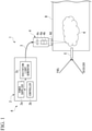
- the laser ignition device 1 is included in a space thruster A (space engine) and is provided at a side of a combustor B.
- the space thruster A is a rocket engine, and includes the combustor B and the laser ignition device 1.
- the space thruster A is a device that generates propulsive force of a rocket by burning an air-fuel mixture K of a fuel and an oxidizer in the combustor B.
- the laser ignition device 1 includes an excitation light source 2, an optical fiber 3, and a pulsed laser oscillator 4.
- the excitation light source 2 includes a power supplier 2a, a controller 2b that controls the power supplier 2a, and an excitation light generator 2c.
- the power supplier 2a is a device that supplies power to the excitation light generator 2c.
- the controller 2b is a control device that controls the power of the power supplier 2a. That is, the controller 2b is a control device that controls the power supplier 2a and controls power supplied from the power supplier 2a to the excitation light generator 2c.
- the controller 2b is connected to, for example, a controller of the space thruster A to control the power supplier 2a according to an operating condition of the space thruster A.
- the controller 2b may include a central processing unit (CPU), a memory such as a random access memory (RAM) and a read only memory (ROM), a storage device such as a hard disk drive (HDD) and a solid state drive (SSD), and an input/output device.
- the excitation light generator 2c generates excitation light using power supplied from the power supplier 2a.
- the excitation light source 2 is provided at a position away from the combustor B.
- the optical fiber 3 connects the excitation light source 2 and the pulsed laser oscillator 4 to each other to guide excitation light generated in the excitation light generator 2c to the pulsed laser oscillator 4.
- the pulsed laser oscillator 4 includes a laser crystal 4a, a Q-switch 4b, a first lens 4c, and a second lens 4d.
- the laser crystal 4a is, for example, a crystal of Nd: YAG (Neodymium-Doped Yttrium Aluminum Garnet).
- the laser crystal 4a is configured to irradiate excitation light and reflect the excitation light by a resonator mirror (not shown).
- the Q-switch 4b is a device that suppresses oscillation for a predetermined period of time by controlling a Q value in the laser crystal 4a and oscillates after the atoms of the laser crystal 4a are excited. As a result, the Q-switch 4b generates a pulsed laser.
- the Q-switch 4b can be operated in a burst light emission mode in which a large number of pulsed light beams (hereinafter, referred to as burst pulses) are generated in a short period of time. That is, the Q-switch 4b generates a plurality of pulsed light beams by burst light emission.
- burst pulses a large number of pulsed light beams
- the first lens 4c is provided at an upper stage (upstream side) of the laser crystal 4a and the Q-switch 4b on an optical path of the excitation light guided to the pulsed laser oscillator 4 by the optical fiber 3 to focus the excitation light.
- the second lens 4d is provided at a position in contact with the combustor B to focus the pulsed laser generated by the Q-switch 4b on the combustible air-fuel mixture K (air-fuel mixture).
- the excitation light when the excitation light is irradiated by the excitation light source 2, the excitation light is guided to the pulsed laser oscillator 4 by the optical fiber 3. Then, in the pulsed laser oscillator 4, the excitation light excites the laser crystal 4a. Subsequently, burst light emission is generated by the Q-switch 4b. As shown by a solid line in Fig. 2 , the burst light emission shows a state in which a plurality of burst pulses (four times in Fig. 2 ) are generated in a short period of time. Total energy in such a plurality of burst pulses is equal to or higher than energy of conventional single pulse light emission shown by a broken line in Fig. 2 . Such burst light emission is focused on the second lens 4d and then irradiated to the combustor B.
- the fuel and the oxidizer are each supplied to the combustor B through a fuel nozzle E.
- the air-fuel mixture K is produced in the vicinity of the fuel nozzle E.
- a flame nucleus is formed in the air-fuel mixture K by a plasma generated by burst light emission (by irradiating burst pulses to the air-fuel mixture K) to propagate the flame.
- a flow of the air-fuel mixture K is formed therein, and the formed flame nucleus moves to a downstream side along the flow.
- a plurality of light emissions by the burst light emission are performed toward the same position with respect to the combustor B, thereby contributing to the formation of a plurality of flame nuclei. That is, the laser ignition device 1 forms a plurality of flame nuclei by the flow of the air-fuel mixture K formed in the combustor B without changing an irradiation position with respect to the combustor B. That is, when the laser ignition device 1 irradiates pulsed light beams a plurality of times to the flowing air-fuel mixture K at the same position in the combustor B, thereby forming a plurality of flame nuclei in the air-fuel mixture K.
- one ignition in the present disclosure shows a period of time in which an initial flame formed by irradiating a pulse in the laser ignition device 1 is spread over an entire engine (combustor B) (when ignition is successful) or the formed initial flame is not spread over the entire engine (combustor B) to misfire (when ignition is failed).
- the temperature distribution in the laser crystal 4a changes by changing an interval of burst pulses.
- the laser spread angle of the laser crystal 4a changes to change a focusing distance even with the same focusing lens (second lens 4d).
- each burst pulse can be irradiated to a gradually different position (a different position in a traveling direction of the pulsed light beams) in the air-fuel mixture K. Therefore, it is possible to change an ignition position of the air-fuel mixture K by changing the interval of burst pulses according to a combustion state.
- Fig. 3 is a graph showing a result when an ignition test is performed using the laser ignition device 1 according to the present embodiment.
- the ignition test was carried out about 100 times under a condition of each number of burst pulses, and an ignition probability was calculated under each condition.
- the ignition probability tends to increase by increasing the number of burst pulses. That is, even when the energy of the burst pulses irradiated at one time is smaller than that of the single pulse, it is possible to obtain a high ignition probability by irradiating the plurality of burst pulses.
- the laser ignition device 1 can be attached to the space thruster A.
- the excitation light source 2 and the pulsed laser oscillator 4 are connected by the optical fiber 3. Therefore, it is not necessary to directly attach the excitation light source 2 to the combustor B, and a degree of freedom of installation of the excitation light source 2 increases.
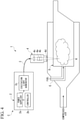
- the laser ignition device 1 may be included in an aero engine C (aircraft engine), and provided for an annular combustor D.
- the aero engine C includes the annular combustor D and the laser ignition device 1, and an air passage for guiding compressed air supplied from a compressor (not shown) is disposed at an outer circumference of the annular combustor D.
- the laser ignition device 1 is attached from a side of the annular combustor D to irradiate burst pulses to the air-fuel mixture K of the fuel injected from the fuel nozzle E and the compressed air, thereby forming a flame nucleus with respect to the air-fuel mixture K to ignite the air-fuel mixture K.
- the laser ignition device 1 may also include an amplifier that amplifies a laser beam.
- the laser beam can be amplified at the time of irradiation, thereby increasing the ignition probability.
- the laser ignition device 1 is applied to the space thruster A and the aero engine C, but the present disclosure is not limited thereto.
- the laser ignition device 1 is applicable to various gas turbine engines.
- the ignition probability can be further increased by changing an interval of burst pulses according to a flow velocity of the air-fuel mixture K in the combustor B or the annular combustor D. Specifically, in a case where the flow velocity in the combustor B or the annular combustor D is relatively high, the interval of burst pulses is reduced. As a result, it is possible to irradiate burst pulses in the vicinity of the generated flame nucleus before the generated flame nucleus is largely swept away, thereby producing a new flame nucleus to increase the ignition probability.
- the ignition probability can be increased by changing the interval and the number of burst pulses according to the type and the air-fuel ratio of the fuel.
- the laser crystal 4a may be a crystal of Nd: YLF (Neodymium-Doped Yttrium Lithium Fluoride) or a crystal of Yb: YAG (Ytterbium-Doped Yttrium Aluminum Garnet).
- Nd Neodymium-Doped Yttrium Lithium Fluoride
- Yb YAG
- Ytterbium-Doped Yttrium Aluminum Garnet Ytterbium-Doped Yttrium Aluminum Garnet
- the present disclosure can be used for a laser ignition device, a space engine and an aircraft engine.
Landscapes
- Engineering & Computer Science (AREA)
- Physics & Mathematics (AREA)
- Electromagnetism (AREA)
- Optics & Photonics (AREA)
- Chemical & Material Sciences (AREA)
- Plasma & Fusion (AREA)
- Combustion & Propulsion (AREA)
- Mechanical Engineering (AREA)
- General Engineering & Computer Science (AREA)
- Crystallography & Structural Chemistry (AREA)
- Lasers (AREA)
Abstract
Description
- The present disclosure relates to a laser ignition device, a space engine and an aircraft engine.
- Priority is claimed on
Japanese Patent Application No. 2019-064157, filed on March 28, 2019 - For example,
Patent Document 1 discloses an engine including a laser ignition plug. In such a laser ignition plug, a high-temperature plasma is generated by irradiating a single pulse to a fuel gas for ignition in a sub-combustion chamber provided in a cylinder head to form a flame nucleus and ignite the fuel gas. -
- [Patent Document 1]
Japanese Unexamined Patent Application No. 2016-33334 - In order to ignite a fuel gas or an air-fuel mixture, applying a predetermined amount of energy to the fuel gas or the air-fuel mixture is needed. For example, in a laser ignition device used in an aerospace engine, a large-sized laser crystal is needed to generate energy needed for ignition with a single pulse. Therefore, the laser ignition device tends to be large in size. However, in the aerospace engine, it may be difficult to mount a large-sized ignition device.
- The present disclosure has been made in view of the above-mentioned problem, and an object of the present disclosure is to reduce a size of the laser ignition device.
- In order to achieve the aforementioned objects, a laser ignition device of a first aspect of the present disclosure includes an excitation light source that generates excitation light, and a pulsed laser oscillator connected to the excitation light source, wherein the pulsed laser oscillator generates a plurality of pulsed light beams at a time of one ignition to produce an initial flame.
- In a laser ignition device of a second aspect of the present disclosure, in the first aspect, the pulsed laser oscillator generates a plurality of pulsed light beams by burst light emission.
- In a laser ignition device of a third aspect of the present disclosure, the laser ignition device of the first or the second aspect includes an optical fiber that connects the excitation light source and the pulsed laser oscillator to each other.
- In a laser ignition device of a fourth aspect of the present disclosure, in any one of the first to third aspects, the pulsed laser oscillator includes a laser crystal and a Q-switch that generates pulsed light beam.
- A space engine of a fifth aspect of the present disclosure includes the laser ignition device of any one of the first to fourth aspects, and a combustor that burns a fuel.
- An aircraft engine of a sixth aspect of the present disclosure includes the laser ignition device of any one of the first to fourth aspects, and a combustor that burns a fuel.
- According to the present disclosure, a plurality of flame nuclei are produced by irradiating a plurality of pulses (pulsed light beams) at a time of one ignition to an air-fuel mixture containing a fuel gas. As a result, it is possible to apply energy in a divisional manner for a plurality of times at the time of one ignition. Therefore, there is no need to generate a large amount of energy in single pulse irradiation, and the size of the laser crystal can be reduced to reduce the size of a
laser ignition device 1. -
-
Fig. 1 is a schematic diagram including a laser ignition device and a space thruster according to an embodiment of the present disclosure. -
Fig. 2 is a graph showing burst light emission in a laser ignition device according to an embodiment of the present disclosure. -
Fig. 3 is a diagram showing a correlation between a number of burst light emissions and an ignition probability according to an embodiment of the present disclosure. -
Fig. 4 is a schematic diagram showing an example in which a laser ignition device according to an embodiment of the present disclosure is applied to a combustor of an aircraft engine. - Hereinafter, an embodiment of a laser ignition device according to the present disclosure will be described with reference to the drawings.
- As shown in
Fig. 1 , thelaser ignition device 1 according to the present embodiment is included in a space thruster A (space engine) and is provided at a side of a combustor B. Further, the space thruster A is a rocket engine, and includes the combustor B and thelaser ignition device 1. The space thruster A is a device that generates propulsive force of a rocket by burning an air-fuel mixture K of a fuel and an oxidizer in the combustor B. Thelaser ignition device 1 includes anexcitation light source 2, anoptical fiber 3, and apulsed laser oscillator 4. - The
excitation light source 2 includes apower supplier 2a, acontroller 2b that controls thepower supplier 2a, and anexcitation light generator 2c. - The
power supplier 2a is a device that supplies power to theexcitation light generator 2c. Thecontroller 2b is a control device that controls the power of thepower supplier 2a. That is, thecontroller 2b is a control device that controls thepower supplier 2a and controls power supplied from thepower supplier 2a to theexcitation light generator 2c. Thecontroller 2b is connected to, for example, a controller of the space thruster A to control thepower supplier 2a according to an operating condition of the space thruster A. Further, thecontroller 2b may include a central processing unit (CPU), a memory such as a random access memory (RAM) and a read only memory (ROM), a storage device such as a hard disk drive (HDD) and a solid state drive (SSD), and an input/output device. Theexcitation light generator 2c generates excitation light using power supplied from thepower supplier 2a. Theexcitation light source 2 is provided at a position away from the combustor B. - The
optical fiber 3 connects theexcitation light source 2 and thepulsed laser oscillator 4 to each other to guide excitation light generated in theexcitation light generator 2c to thepulsed laser oscillator 4. - The
pulsed laser oscillator 4 includes alaser crystal 4a, a Q-switch 4b, afirst lens 4c, and asecond lens 4d. - The
laser crystal 4a is, for example, a crystal of Nd: YAG (Neodymium-Doped Yttrium Aluminum Garnet). Thelaser crystal 4a is configured to irradiate excitation light and reflect the excitation light by a resonator mirror (not shown). The Q-switch 4b is a device that suppresses oscillation for a predetermined period of time by controlling a Q value in thelaser crystal 4a and oscillates after the atoms of thelaser crystal 4a are excited. As a result, the Q-switch 4b generates a pulsed laser. Further, the Q-switch 4b can be operated in a burst light emission mode in which a large number of pulsed light beams (hereinafter, referred to as burst pulses) are generated in a short period of time. That is, the Q-switch 4b generates a plurality of pulsed light beams by burst light emission. - The
first lens 4c is provided at an upper stage (upstream side) of thelaser crystal 4a and the Q-switch 4b on an optical path of the excitation light guided to thepulsed laser oscillator 4 by theoptical fiber 3 to focus the excitation light. Thesecond lens 4d is provided at a position in contact with the combustor B to focus the pulsed laser generated by the Q-switch 4b on the combustible air-fuel mixture K (air-fuel mixture). - In the
laser ignition device 1, when the excitation light is irradiated by theexcitation light source 2, the excitation light is guided to thepulsed laser oscillator 4 by theoptical fiber 3. Then, in thepulsed laser oscillator 4, the excitation light excites thelaser crystal 4a. Subsequently, burst light emission is generated by the Q-switch 4b. As shown by a solid line inFig. 2 , the burst light emission shows a state in which a plurality of burst pulses (four times inFig. 2 ) are generated in a short period of time. Total energy in such a plurality of burst pulses is equal to or higher than energy of conventional single pulse light emission shown by a broken line inFig. 2 . Such burst light emission is focused on thesecond lens 4d and then irradiated to the combustor B. - In the space thruster A, as shown in
Fig. 1 , the fuel and the oxidizer are each supplied to the combustor B through a fuel nozzle E. As a result, in the combustor B, the air-fuel mixture K is produced in the vicinity of the fuel nozzle E. With respect to the air-fuel mixture K, a flame nucleus is formed in the air-fuel mixture K by a plasma generated by burst light emission (by irradiating burst pulses to the air-fuel mixture K) to propagate the flame. In the combustor B, a flow of the air-fuel mixture K is formed therein, and the formed flame nucleus moves to a downstream side along the flow. Furthermore, a plurality of light emissions by the burst light emission are performed toward the same position with respect to the combustor B, thereby contributing to the formation of a plurality of flame nuclei. That is, thelaser ignition device 1 forms a plurality of flame nuclei by the flow of the air-fuel mixture K formed in the combustor B without changing an irradiation position with respect to the combustor B. That is, when thelaser ignition device 1 irradiates pulsed light beams a plurality of times to the flowing air-fuel mixture K at the same position in the combustor B, thereby forming a plurality of flame nuclei in the air-fuel mixture K. Then, the plurality of flame nuclei are combined while flowing to a downstream side to grow as one large initial flame. Further, one ignition in the present disclosure shows a period of time in which an initial flame formed by irradiating a pulse in thelaser ignition device 1 is spread over an entire engine (combustor B) (when ignition is successful) or the formed initial flame is not spread over the entire engine (combustor B) to misfire (when ignition is failed). - Further, in the
laser ignition device 1, the temperature distribution in thelaser crystal 4a changes by changing an interval of burst pulses. As a result, the laser spread angle of thelaser crystal 4a changes to change a focusing distance even with the same focusing lens (second lens 4d). Thereby, each burst pulse can be irradiated to a gradually different position (a different position in a traveling direction of the pulsed light beams) in the air-fuel mixture K. Therefore, it is possible to change an ignition position of the air-fuel mixture K by changing the interval of burst pulses according to a combustion state. -
Fig. 3 is a graph showing a result when an ignition test is performed using thelaser ignition device 1 according to the present embodiment. In this graph, the ignition test was carried out about 100 times under a condition of each number of burst pulses, and an ignition probability was calculated under each condition. As shown inFig. 3 , in thelaser ignition device 1, the ignition probability tends to increase by increasing the number of burst pulses. That is, even when the energy of the burst pulses irradiated at one time is smaller than that of the single pulse, it is possible to obtain a high ignition probability by irradiating the plurality of burst pulses. Therefore, it is possible to increase energy density by burst light emission without using a large-sized laser crystal that generates a laser having a high energy density, thereby reducing the size of thelaser ignition device 1. As a result, thelaser ignition device 1 can be attached to the space thruster A. - In addition, according to the
laser ignition device 1 according to the present embodiment, theexcitation light source 2 and thepulsed laser oscillator 4 are connected by theoptical fiber 3. Therefore, it is not necessary to directly attach theexcitation light source 2 to the combustor B, and a degree of freedom of installation of theexcitation light source 2 increases. - Although the embodiments of the present disclosure have been described above with reference to the drawings, the present disclosure is not limited to the above embodiments. The various shapes, combinations, and the like of respective constituent members shown in the above-described embodiments are merely examples, and various changes can be made based on design requirements and the like within the scope of the present disclosure defined in the claims.
- For example, as shown in
Fig. 4 , thelaser ignition device 1 may be included in an aero engine C (aircraft engine), and provided for an annular combustor D. The aero engine C includes the annular combustor D and thelaser ignition device 1, and an air passage for guiding compressed air supplied from a compressor (not shown) is disposed at an outer circumference of the annular combustor D. In such a configuration, thelaser ignition device 1 is attached from a side of the annular combustor D to irradiate burst pulses to the air-fuel mixture K of the fuel injected from the fuel nozzle E and the compressed air, thereby forming a flame nucleus with respect to the air-fuel mixture K to ignite the air-fuel mixture K. - Moreover, the
laser ignition device 1 may also include an amplifier that amplifies a laser beam. As a result, the laser beam can be amplified at the time of irradiation, thereby increasing the ignition probability. - In the above embodiment, the
laser ignition device 1 is applied to the space thruster A and the aero engine C, but the present disclosure is not limited thereto. Thelaser ignition device 1 is applicable to various gas turbine engines. - Besides, the ignition probability can be further increased by changing an interval of burst pulses according to a flow velocity of the air-fuel mixture K in the combustor B or the annular combustor D. Specifically, in a case where the flow velocity in the combustor B or the annular combustor D is relatively high, the interval of burst pulses is reduced. As a result, it is possible to irradiate burst pulses in the vicinity of the generated flame nucleus before the generated flame nucleus is largely swept away, thereby producing a new flame nucleus to increase the ignition probability.
- In addition, energy needed for ignition differs depending on a type and an air-fuel ratio of the fuel. Therefore, the ignition probability can be increased by changing the interval and the number of burst pulses according to the type and the air-fuel ratio of the fuel.
- Moreover, the
laser crystal 4a may be a crystal of Nd: YLF (Neodymium-Doped Yttrium Lithium Fluoride) or a crystal of Yb: YAG (Ytterbium-Doped Yttrium Aluminum Garnet). - The present disclosure can be used for a laser ignition device, a space engine and an aircraft engine.
-
- 1:
- Laser ignition device
- 2:
- Excitation light source
- 2a:
- Power supplier
- 2b:
- Controller
- 2c:
- Excitation light generator
- 3:
- Optical fiber
- 4:
- Pulsed laser oscillator
- 4a:
- Laser crystal
- 4b:
- Q-switch
- 4c:
- First lens
- 4d:
- Second lens
- A:
- Space thruster
- B:
- Combustor
- C:
- Aero engine
- D:
- Annular combustor
- E:
- Fuel nozzle
Claims (6)
- A laser ignition device comprising:an excitation light source that generates excitation light; anda pulsed laser oscillator connected to the excitation light source, whereinthe pulsed laser oscillator generates a plurality of pulsed light beams at a time of one ignition to produce an initial flame.
- The laser ignition device according to Claim 1, wherein
the pulsed laser oscillator generates a plurality of pulsed light beams by burst light emission. - The laser ignition device according to Claim 1 or 2, further comprising
an optical fiber that connects the excitation light source and the pulsed laser oscillator to each other. - The laser ignition device according to any one of Claims 1 to 3, wherein
the pulsed laser oscillator includes a laser crystal and a Q-switch that generates pulsed light beam. - A space engine comprising:the laser ignition device according to any one of Claims 1 to 4; anda combustor that burns a fuel.
- An aircraft engine comprising:the laser ignition device according to any one of Claims 1 to 4; anda combustor that burns a fuel.
Applications Claiming Priority (2)
| Application Number | Priority Date | Filing Date | Title |
|---|---|---|---|
| JP2019064157A JP2020165332A (en) | 2019-03-28 | 2019-03-28 | Laser igniter, space engine and aircraft engine |
| PCT/JP2020/013200 WO2020196579A1 (en) | 2019-03-28 | 2020-03-25 | Laser ignition device, space engine, and aircraft engine |
Publications (2)
| Publication Number | Publication Date |
|---|---|
| EP3951158A1 true EP3951158A1 (en) | 2022-02-09 |
| EP3951158A4 EP3951158A4 (en) | 2023-01-04 |
Family
ID=72611221
Family Applications (1)
| Application Number | Title | Priority Date | Filing Date |
|---|---|---|---|
| EP20779598.0A Withdrawn EP3951158A4 (en) | 2019-03-28 | 2020-03-25 | LASER IGNITION DEVICE, SPACECRAFT ENGINE AND AIRCRAFT ENGINE |
Country Status (4)
| Country | Link |
|---|---|
| US (1) | US20220010753A1 (en) |
| EP (1) | EP3951158A4 (en) |
| JP (1) | JP2020165332A (en) |
| WO (1) | WO2020196579A1 (en) |
Families Citing this family (2)
| Publication number | Priority date | Publication date | Assignee | Title |
|---|---|---|---|---|
| RU2770975C2 (en) * | 2019-06-20 | 2022-04-25 | Акционерное общество "НПО Энергомаш имени академика В.П. Глушко" | Apparatus for laser ignition of fuel components in a combustion chamber or gas generator of a liquid rocket engine |
| WO2024102531A2 (en) * | 2022-10-04 | 2024-05-16 | Vogue Aerospace & Defense, Inc. | Bobbin-form solid controlled and filament fed hybrid propulsion methods for space vehicle innovative architectures |
Family Cites Families (18)
| Publication number | Priority date | Publication date | Assignee | Title |
|---|---|---|---|---|
| JPS57200672A (en) * | 1981-06-02 | 1982-12-08 | Nippon Soken Inc | Laser igniting apparatus for internal-combustion engine |
| US5404712A (en) * | 1992-10-06 | 1995-04-11 | University Of Tennessee Research Corporation | Laser initiated non-linear fuel droplet ignition |
| WO1998048221A2 (en) * | 1997-04-21 | 1998-10-29 | The Regents Of The University Of California | Laser ignition |
| US6302682B1 (en) * | 1998-02-27 | 2001-10-16 | The Regents Of The University Of California | Laser controlled flame stabilization |
| US6105370A (en) * | 1998-08-18 | 2000-08-22 | Hamilton Sundstrand Corporation | Method and apparatus for rejecting waste heat from a system including a combustion engine |
| AU2000235236A1 (en) * | 2000-03-10 | 2001-09-24 | The Regents Of The University Of California | Laser ignition |
| US7093448B2 (en) * | 2003-10-08 | 2006-08-22 | Honeywell International, Inc. | Multi-action on multi-surface seal with turbine scroll retention method in gas turbine engine |
| JP4590537B2 (en) * | 2005-04-28 | 2010-12-01 | 株式会社デンソー | Laser ignition device |
| DE102006024679A1 (en) * | 2006-05-26 | 2007-11-29 | Robert Bosch Gmbh | Ignition device for motor vehicle`s internal-combustion engine, has laser device to generate laser light for radiation into chamber, with refraction device that is arranged as single piece and refracts part of pump light from light source |
| US7421166B1 (en) * | 2006-08-04 | 2008-09-02 | The United States Of America As Represented By The United States Department Of Energy | Laser spark distribution and ignition system |
| WO2009008524A1 (en) * | 2007-07-12 | 2009-01-15 | Imagineering, Inc. | Ignition and chemical reaction accelerator and flame stabilizer, speed-type internal combustion engine, and furnace |
| DE102010027943A1 (en) * | 2010-04-20 | 2011-10-20 | Robert Bosch Gmbh | Method for operating a laser spark plug for an internal combustion engine |
| US8689536B2 (en) * | 2010-11-30 | 2014-04-08 | General Electric Company | Advanced laser ignition systems for gas turbines including aircraft engines |
| US9085988B2 (en) * | 2010-12-24 | 2015-07-21 | Rolls-Royce North American Technologies, Inc. | Gas turbine engine flow path member |
| JP6457759B2 (en) | 2014-07-31 | 2019-01-23 | 三菱重工エンジン&ターボチャージャ株式会社 | Engine with laser spark plug |
| EP3386041B1 (en) * | 2015-12-02 | 2023-04-05 | Ricoh Company, Ltd. | Laser device, ignition device, and internal combustion engine |
| US20180252868A1 (en) * | 2017-03-03 | 2018-09-06 | Government Of The United States As Represented By The Secretary Of The Air Force | Method and system for fiber-coupled, laser-assisted ignition in fuel-lean, high-speed flows |
| JP7047312B2 (en) | 2017-09-29 | 2022-04-05 | ブラザー工業株式会社 | Liquid discharge head |
-
2019
- 2019-03-28 JP JP2019064157A patent/JP2020165332A/en active Pending
-
2020
- 2020-03-25 WO PCT/JP2020/013200 patent/WO2020196579A1/en not_active Ceased
- 2020-03-25 EP EP20779598.0A patent/EP3951158A4/en not_active Withdrawn
-
2021
- 2021-09-27 US US17/485,567 patent/US20220010753A1/en not_active Abandoned
Also Published As
| Publication number | Publication date |
|---|---|
| JP2020165332A (en) | 2020-10-08 |
| EP3951158A4 (en) | 2023-01-04 |
| WO2020196579A1 (en) | 2020-10-01 |
| US20220010753A1 (en) | 2022-01-13 |
Similar Documents
| Publication | Publication Date | Title |
|---|---|---|
| JP5352876B2 (en) | Ignition / chemical reaction promotion / flame holding device, speed internal combustion engine, and furnace | |
| Tauer et al. | Laser‐initiated ignition | |
| O’Briant et al. | Laser ignition for aerospace propulsion | |
| US5756924A (en) | Multiple laser pulse ignition method and apparatus | |
| US5598699A (en) | Laser initiated non-linear fuel droplet ignition apparatus | |
| JP6153700B2 (en) | Advanced optics and optical access for laser ignition systems for gas turbines including aircraft engines | |
| JP5860202B2 (en) | Laser ignition system and method for internal combustion engines | |
| JP2009036197A5 (en) | ||
| WO2001033073A1 (en) | Ignition system for an internal combustion engine | |
| US20220010753A1 (en) | Laser ignition device, space engine, and aircraft engine | |
| EP0816674A1 (en) | Ignition methods and apparatus using broadband laser energy | |
| CN109736993A (en) | A 2μm band laser ignition device and ignition method | |
| Vasile et al. | Multi-point laser-induced ignition of air-methane mixtures by a high peak-power passively Q-switched Nd: YAG/Cr4+: YAG laser | |
| Wermer et al. | Spark and flame kernel interaction with dual-pulse laser-induced spark ignition in a lean premixed methane–air flow | |
| RU2468240C1 (en) | Chamber of liquid-propellant rocket engine or gas generator with laser ignition device of fuel components, and its startup method | |
| JP4257420B2 (en) | Laser multi-point ignition system for internal combustion engines | |
| LIOU | Laser ignition in liquid rocket engines | |
| Singh et al. | Spatio-temporal effect of the breakdown zone in the laser-initiated ignition of atomized ethyl alcohol-air mixture | |
| Tsunekane et al. | for Ignition of Automobile Engines | |
| JPWO2017094778A1 (en) | Laser device, ignition device and internal combustion engine | |
| McMillian et al. | Laser spark ignition: laser development and engine testing | |
| Osborne et al. | Evaluation and characterization study of dual pulse laser-induced spark (DPLIS) for rocket engine ignition system application | |
| Mori et al. | Ignition characteristics of GH2/GOx mixture using laser ablation ignition | |
| Suchomel et al. | Perspectives on cataloging plasma technologies applied to aeronautical sciences | |
| RU2679949C1 (en) | Method for launching the camera of a liquid rocket engine or a gas generator with laser igniting fuel and device for its implementation |
Legal Events
| Date | Code | Title | Description |
|---|---|---|---|
| STAA | Information on the status of an ep patent application or granted ep patent |
Free format text: STATUS: THE INTERNATIONAL PUBLICATION HAS BEEN MADE |
|
| PUAI | Public reference made under article 153(3) epc to a published international application that has entered the european phase |
Free format text: ORIGINAL CODE: 0009012 |
|
| STAA | Information on the status of an ep patent application or granted ep patent |
Free format text: STATUS: REQUEST FOR EXAMINATION WAS MADE |
|
| 17P | Request for examination filed |
Effective date: 20210930 |
|
| AK | Designated contracting states |
Kind code of ref document: A1 Designated state(s): AL AT BE BG CH CY CZ DE DK EE ES FI FR GB GR HR HU IE IS IT LI LT LU LV MC MK MT NL NO PL PT RO RS SE SI SK SM TR |
|
| DAV | Request for validation of the european patent (deleted) | ||
| DAX | Request for extension of the european patent (deleted) | ||
| REG | Reference to a national code |
Ref country code: DE Ref legal event code: R079 Free format text: PREVIOUS MAIN CLASS: F02K0009950000 Ipc: F02C0007264000 |
|
| RIC1 | Information provided on ipc code assigned before grant |
Ipc: F02P 23/04 20060101ALI20221109BHEP Ipc: F02K 9/95 20060101ALI20221109BHEP Ipc: F02C 7/264 20060101AFI20221109BHEP |
|
| RIC1 | Information provided on ipc code assigned before grant |
Ipc: F02P 23/04 20060101ALI20221116BHEP Ipc: F02K 9/95 20060101ALI20221116BHEP Ipc: F02C 7/264 20060101AFI20221116BHEP |
|
| A4 | Supplementary search report drawn up and despatched |
Effective date: 20221201 |
|
| RIC1 | Information provided on ipc code assigned before grant |
Ipc: F02P 23/04 20060101ALI20221125BHEP Ipc: F02K 9/95 20060101ALI20221125BHEP Ipc: F02C 7/264 20060101AFI20221125BHEP |
|
| STAA | Information on the status of an ep patent application or granted ep patent |
Free format text: STATUS: THE APPLICATION HAS BEEN WITHDRAWN |
|
| 18W | Application withdrawn |
Effective date: 20240216 |