EP3951138A1 - Stationary blade segment of axial turbine - Google Patents
Stationary blade segment of axial turbine Download PDFInfo
- Publication number
- EP3951138A1 EP3951138A1 EP19921773.8A EP19921773A EP3951138A1 EP 3951138 A1 EP3951138 A1 EP 3951138A1 EP 19921773 A EP19921773 A EP 19921773A EP 3951138 A1 EP3951138 A1 EP 3951138A1
- Authority
- EP
- European Patent Office
- Prior art keywords
- airfoil
- hub portion
- stator vane
- vane segment
- airfoil portions
- Prior art date
- Legal status (The legal status is an assumption and is not a legal conclusion. Google has not performed a legal analysis and makes no representation as to the accuracy of the status listed.)
- Granted
Links
Images


Classifications
-
- F—MECHANICAL ENGINEERING; LIGHTING; HEATING; WEAPONS; BLASTING
- F01—MACHINES OR ENGINES IN GENERAL; ENGINE PLANTS IN GENERAL; STEAM ENGINES
- F01D—NON-POSITIVE DISPLACEMENT MACHINES OR ENGINES, e.g. STEAM TURBINES
- F01D5/00—Blades; Blade-carrying members; Heating, heat-insulating, cooling or antivibration means on the blades or the members
- F01D5/12—Blades
- F01D5/14—Form or construction
- F01D5/141—Shape, i.e. outer, aerodynamic form
-
- F—MECHANICAL ENGINEERING; LIGHTING; HEATING; WEAPONS; BLASTING
- F01—MACHINES OR ENGINES IN GENERAL; ENGINE PLANTS IN GENERAL; STEAM ENGINES
- F01D—NON-POSITIVE DISPLACEMENT MACHINES OR ENGINES, e.g. STEAM TURBINES
- F01D9/00—Stators
- F01D9/02—Nozzles; Nozzle boxes; Stator blades; Guide conduits, e.g. individual nozzles
-
- F—MECHANICAL ENGINEERING; LIGHTING; HEATING; WEAPONS; BLASTING
- F01—MACHINES OR ENGINES IN GENERAL; ENGINE PLANTS IN GENERAL; STEAM ENGINES
- F01D—NON-POSITIVE DISPLACEMENT MACHINES OR ENGINES, e.g. STEAM TURBINES
- F01D5/00—Blades; Blade-carrying members; Heating, heat-insulating, cooling or antivibration means on the blades or the members
- F01D5/12—Blades
- F01D5/14—Form or construction
- F01D5/141—Shape, i.e. outer, aerodynamic form
- F01D5/145—Means for influencing boundary layers or secondary circulations
-
- F—MECHANICAL ENGINEERING; LIGHTING; HEATING; WEAPONS; BLASTING
- F05—INDEXING SCHEMES RELATING TO ENGINES OR PUMPS IN VARIOUS SUBCLASSES OF CLASSES F01-F04
- F05D—INDEXING SCHEME FOR ASPECTS RELATING TO NON-POSITIVE-DISPLACEMENT MACHINES OR ENGINES, GAS-TURBINES OR JET-PROPULSION PLANTS
- F05D2220/00—Application
- F05D2220/30—Application in turbines
- F05D2220/32—Application in turbines in gas turbines
-
- F—MECHANICAL ENGINEERING; LIGHTING; HEATING; WEAPONS; BLASTING
- F05—INDEXING SCHEMES RELATING TO ENGINES OR PUMPS IN VARIOUS SUBCLASSES OF CLASSES F01-F04
- F05D—INDEXING SCHEME FOR ASPECTS RELATING TO NON-POSITIVE-DISPLACEMENT MACHINES OR ENGINES, GAS-TURBINES OR JET-PROPULSION PLANTS
- F05D2240/00—Components
- F05D2240/10—Stators
- F05D2240/12—Fluid guiding means, e.g. vanes
-
- F—MECHANICAL ENGINEERING; LIGHTING; HEATING; WEAPONS; BLASTING
- F05—INDEXING SCHEMES RELATING TO ENGINES OR PUMPS IN VARIOUS SUBCLASSES OF CLASSES F01-F04
- F05D—INDEXING SCHEME FOR ASPECTS RELATING TO NON-POSITIVE-DISPLACEMENT MACHINES OR ENGINES, GAS-TURBINES OR JET-PROPULSION PLANTS
- F05D2250/00—Geometry
- F05D2250/70—Shape
-
- F—MECHANICAL ENGINEERING; LIGHTING; HEATING; WEAPONS; BLASTING
- F05—INDEXING SCHEMES RELATING TO ENGINES OR PUMPS IN VARIOUS SUBCLASSES OF CLASSES F01-F04
- F05D—INDEXING SCHEME FOR ASPECTS RELATING TO NON-POSITIVE-DISPLACEMENT MACHINES OR ENGINES, GAS-TURBINES OR JET-PROPULSION PLANTS
- F05D2250/00—Geometry
- F05D2250/70—Shape
- F05D2250/71—Shape curved
-
- F—MECHANICAL ENGINEERING; LIGHTING; HEATING; WEAPONS; BLASTING
- F05—INDEXING SCHEMES RELATING TO ENGINES OR PUMPS IN VARIOUS SUBCLASSES OF CLASSES F01-F04
- F05D—INDEXING SCHEME FOR ASPECTS RELATING TO NON-POSITIVE-DISPLACEMENT MACHINES OR ENGINES, GAS-TURBINES OR JET-PROPULSION PLANTS
- F05D2250/00—Geometry
- F05D2250/70—Shape
- F05D2250/71—Shape curved
- F05D2250/712—Shape curved concave
-
- Y—GENERAL TAGGING OF NEW TECHNOLOGICAL DEVELOPMENTS; GENERAL TAGGING OF CROSS-SECTIONAL TECHNOLOGIES SPANNING OVER SEVERAL SECTIONS OF THE IPC; TECHNICAL SUBJECTS COVERED BY FORMER USPC CROSS-REFERENCE ART COLLECTIONS [XRACs] AND DIGESTS
- Y02—TECHNOLOGIES OR APPLICATIONS FOR MITIGATION OR ADAPTATION AGAINST CLIMATE CHANGE
- Y02T—CLIMATE CHANGE MITIGATION TECHNOLOGIES RELATED TO TRANSPORTATION
- Y02T50/00—Aeronautics or air transport
- Y02T50/60—Efficient propulsion technologies, e.g. for aircraft
Definitions
- the present disclosure relates to a stator vane segment of an axial turbine.
- a gas turbine engine such as a turbofan engine includes a compressor, a combustor, and a turbine as main components.
- the turbine is a turbo machine that has a function of converting thermal energy of combustion gas generated by the combustor into rotational energy.
- turbines such as an axial flow type and a radial flow type.
- axial turbine axial turbine
- this axial turbine will be described below.
- the axial turbine includes one or more stages arrayed in the axial direction, and each stage is composed of a stator vane row disposed on the upstream side and a rotor blade row disposed on the downstream side.
- the stator vane row is usually formed from a plurality of stator vane segments arranged side by side in the circumferential direction, and each stator vane segment includes an airfoil portion, and an outer band and an inner band joined to a tip portion (radially outer end) and a hub portion (radially inner end) of each airfoil portion, respectively.
- Each airfoil portion further includes a leading edge and a trailing edge, and a concave pressure surface and a convex suction surface each extending between the leading edge and the trailing edge.
- the stator vane segment is cantilevered by a casing through fixing of the outer band to an inner circumference of the substantially cylindrical casing.
- the outer band and the inner band each have such a shape as to form a ring as a whole in a state in which all the stator vane segments composing the stator vane row are attached to the casing.
- a radially inner surface of the outer band and a radially outer surface of the inner band form radially inner and outer boundary surfaces of a combustion gas flow path, respectively.
- the stator vane segment may be formed in a mode (single vane) in which only one airfoil portion is provided between the outer band and the inner band, or may be formed in a mode (coupled vane) in which a plurality of airfoil portions are provided between the outer band and the inner band.
- Patent Document 1 discloses a stator vane segment having three airfoil portions between an outer band and an inner band.
- Patent Document 1 Japanese Patent No. 4474989
- stator vane segment formed as a coupled vane is also cantilevered by the casing through fixing of the outer band to the inner circumference of the casing, and therefore deformation of the outer band is restrained, while the inner band is in a state of being freely deformable.
- the radially outer surface of the inner band is exposed to the flow of combustion gas, while the radially inner surface of the inner band is in contact with the air of a significantly lower temperature than the combustion gas (generally, air extracted from the compressor composing the gas turbine engine).
- the radially outer side of the inner band is largely thermally expanded in the circumferential direction as compared with the radially inner side, and therefore the inner band is deformed in such a manner that the curvature of the inner band is increased as compared with a normal temperature state.
- the airfoil portion disposed at the circumferential end of the inner band, of the airfoil portions constituting the stator vane segment formed as a coupled vane is pulled relatively largely inward in the radial direction.
- high stress is generated on the suction surface near the hub portion.
- An object of the present disclosure which has been made in view of the above problems, is to provide a stator vane segment of an axial turbine formed as a coupled vane, the stator vane segment being capable of reducing stress generated on a suction surface near a hub portion of an airfoil portion having a suction surface located on a circumferential end side of an inner band without causing increase in weight.
- a stator vane segment of an axial turbine of the present disclosure includes: a plurality of airfoil portions; one outer band joined to a tip portion of each of the plurality of airfoil portions and one inner band joined to a hub portion of each of the plurality of airfoil portions, wherein each of the plurality of airfoil portions is formed by stacking airfoil profiles in a spanwise direction from the hub portion to the tip portion, and each of the profiles includes a leading edge and a trailing edge, and a concave pressure surface and a convex suction surface each extending between the leading edge and the trailing edge, in a stacking line obtained by connecting the respective trailing edges of the profiles at spanwise positions, a portion from the tip portion to a predetermined spanwise position is a straight line parallel to a radial direction of the axial turbine, a portion from the predetermined spanwise position to the hub portion is shifted from the pressure surface toward the suction surface in a circumfer
- stator vane segment of an axial turbine of the present disclosure it is possible to obtain an excellent effect that it is possible to reduce stress generated on a suction surface near a hub portion of an airfoil portion having the suction surface located on a circumferential end side of an inner band without causing increase in weight.
- FIGS. 1A and 1B are schematic perspective views of a stator vane segment of the embodiment of the present disclosure as viewed from the front side and the rear side, respectively.
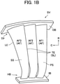
- a stator vane segment SV of the embodiment of the present disclosure includes three airfoil portions AF, and an outer band OB and an inner band IB joined to respective tip portions TP (outer end portions in the radial direction R) and hub portions HB (inner end portions in the radial direction R) of the airfoil portions AF, respectively.
- Each airfoil portion SV includes a leading edge LE and a trailing edge TE, and a concave pressure surface PS and a convex suction surface SS each extending between the leading edge LE and the trailing edge TE.
- first airfoil portion AF1 one whose pressure surface PS is located on the second end side in the circumferential direction C of the stator vane segment SV
- third airfoil portion AF3 one whose suction surface SS is located on the first end side in the circumferential direction C of the stator vane segment SV
- second airfoil portion AF2 one disposed between the first airfoil portion AF1 and the third airfoil portion AF3 is referred to as a second airfoil portion AF2.
- the airfoil portions AF are each formed by stacking airfoil cross sections (profiles) perpendicular to the radial direction R in the spanwise direction from the hub portion HB to the tip portion TP (this is referred to as stacking).
- the stacking mode is defined by the shape of a line connecting representative points of the profiles at spanwise positions (this is referred to as a stacking line), and in the stator vane segment SV, the trailing edge of each profile is adopted as this representative point. Therefore, the stacking line SL of each airfoil portion AF (AF1 to AF3) of the stator vane segment SV coincides with the corresponding trailing edge TE.
- the stacking line SL of each airfoil portion AF of the stator vane segment SV that is, the trailing edge TE is a straight line parallel to the radial direction R up to a predetermined spanwise position (hereinafter referred to as a shift start position X) from the tip portion TP toward the hub portion HB, but a portion from the shift start position X (see FIG. 2 ) to the hub portion HB (that is, in a region near the hub portion HB) is shifted in the circumferential direction C in the direction from the pressure surface PS toward the suction surface SS (to the right in FIG. 1A , and to the left in FIG. 1B ).
- a shift start position X a predetermined spanwise position
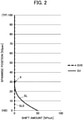
- FIG. 2 is a graph illustrating a shape of the stacking line SL of each airfoil portion AF (AF1 to AF3) of the stator vane segment SV of the embodiment of the present disclosure.
- the vertical axis of the graph illustrates the spanwise position
- the horizontal axis illustrates a shift amount in the circumferential direction C (direction from the pressure surface PS toward the suction surface SS) of the stacking line SL.
- the spanwise position plotted on the vertical axis is the percentage (% Span) of a dimensionless value obtained by dividing the height measured from the hub portion HB of each airfoil portion AF by the total height of each airfoil portion AF (height from the hub portion HB to the tip portion TP; Span), and 0% Span and 100% Span correspond to the hub portion HB and the chip TP portion, respectively.
- the shift amount plotted on the horizontal axis is the percentage (% Pitch) of a dimensionless value obtained by division by a circumferential interval in the hub portion HB of each airfoil portion AF, that is, a Pitch.
- the shift amount of the stacking line SL0 in the circumferential direction C is zero (0% Pitch) over the entire region in the spanwise direction from the tip portion TP (100% Span) to the hub portion HB (0% Span) (see broken line in FIG. 2 ).
- the shift amount of the stacking line SL in the circumferential direction C is zero (0% Pitch) in a portion up to 30% Span from the tip portion TP (100% Span) toward the hub portion HB, but increases monotonically from 0% Pitch to 50% Pitch in a portion from 30% Span toward the hub portion HB (0% Span) (see the solid line in Fig. 2 ).
- the shift start position X is 30% Span, and the maximum shift amount (shift amount at the hub portion HB) is 50% Pitch.
- the shift start position X can be appropriately selected within a range of 10 to 50% Span, and the maximum shift amount can be appropriately selected within a range of 10 to 100% Pitch.
- a curved line representing change in the shift amount from the shift start position X to the hub portion HB is a curved line without an elbow (that is, a smooth curve) connected to a straight line from the tip portion TP to the shift start position X smoothly (that is, in such a manner as to share a tangent line) at the shift start position X, and can be, for example, a quadratic curve.
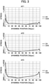
- FIG. 3 illustrates a result of an obtained spanwise distribution of stress generated on the suction surface SS of each airfoil portion AF (AF1 to AF3) in an operating state of a turbine (gas turbine engine), in the stator vane segment SV formed in described above.
- each graph also illustrates a spanwise distribution of stress in the conventional stator vane segment SV0.
- stator vane segment SV of the embodiment of the present disclosure in any of the first airfoil portion AF1 to the third airfoil portion AF3, stress generated in the region near the hub portion HB (0% Span) is lower than that of the conventional stator vane segment SV0.
- a peak of the total pressure loss coefficient due to secondary flow in the region near the hub portion HB (0% Span) is smaller than that of the conventional stator vane segment SV0. It is considered that this is because the stacking line SL is shifted in the circumferential direction C in the region near the hub portion HB, so that the secondary flow is suppressed.
- the stress generated on the suction surface SS in the region near the hub portion HB can be reduced as compared to the conventional stator vane segment SV0, and it is possible to obtain an excellent effect that the total pressure loss due to the secondary flow in the above region can be suppressed to a low level. Moreover, this effect is obtained only by deformation of the stacking line SL (shift in the circumferential direction C in the region near the hub portion HB), and does not cause increase in weight.
- the effect of the reduction in the stress generated on the suction surface SS in the region near the hub portion HB is large in the airfoil portions AF (the first airfoil portion AF1 and the third airfoil portion AF3) disposed at the ends of the stator vane segment SV in the circumferential direction C, and is the largest in the third airfoil portion AF3 having the suction surface SS located on the end side in the circumferential direction C of the stator vane segment SV.
- the shape of the stacking line SL applied to all the airfoil portions AF in the aforementioned stator vane segment SV may be applied only to the third airfoil portion AF3 where a particularly large stress reduction effect can be obtained.
- the maximum shift amounts that are the same for all airfoil portions AF in the aforementioned stator vane segment SV may be changed such that the maximum shift amount in the third airfoil portion AF3 that can obtain a particularly large stress reduction effect is made larger than other airfoil portions (the first airfoil portion AF1 and the second airfoil portion AF2).
- the pitch in the hub portion HB of the airfoil portion AF becomes nonuniform in the circumferential direction C, but care should be taken such that a throat area does not change as a whole of the stator vane row formed by the stator vane segment SV. Consequently, it is possible to avoid an adverse effect on aerodynamic performance.
- the stator vane segment SV includes the three airfoil portions AF
- the number N of the airfoil portions AF included in the stator vane segment SV may be 4 or more.
- the shift in the circumferential direction C in the region near the hub portion HB of the stacking line SL may be applied only to an N-th airfoil portion AFN having a suction surface SS located on one of the end sides in the circumferential direction C of the stator vane segment SV, or the maximum shift amount of the N-th airfoil portion AFN may be made larger than those of other airfoil portions.
- a stator vane segment of an axial turbine of a first aspect of the present disclosure includes: a plurality of airfoil portions; one outer band joined to a tip portion of each of the plurality of airfoil portions; and one inner band joined to a hub portion of each of the plurality of airfoil portions, wherein each of the plurality of airfoil portions is formed by stacking airfoil profiles in a spanwise direction from the hub portion to the tip portion, and each of the profiles includes a leading edge and a trailing edge, and a concave pressure surface and a convex suction surface each extending between the leading edge and the trailing edge, in a stacking line obtained by connecting the respective trailing edges of the profiles at spanwise positions, a portion from the tip portion to a predetermined spanwise position is a straight line parallel to a radial direction of the axial turbine, a portion from the predetermined spanwise position to the hub portion is shifted from the pressure surface toward the suction surface in a circumferential direction of the
- the predetermined spanwise position is 10 to 50%.
- the amount of the shift in the hub portion is 0 to 100%.
Landscapes
- Engineering & Computer Science (AREA)
- Mechanical Engineering (AREA)
- General Engineering & Computer Science (AREA)
- Physics & Mathematics (AREA)
- Fluid Mechanics (AREA)
- Turbine Rotor Nozzle Sealing (AREA)
Abstract
Description
- The present disclosure relates to a stator vane segment of an axial turbine.
- For example, a gas turbine engine such as a turbofan engine includes a compressor, a combustor, and a turbine as main components.
- Among these, the turbine is a turbo machine that has a function of converting thermal energy of combustion gas generated by the combustor into rotational energy. There are types of turbines such as an axial flow type and a radial flow type. In a gas turbine engine, an axial flow type turbine (axial turbine) is often adopted, and this axial turbine will be described below.
- The axial turbine includes one or more stages arrayed in the axial direction, and each stage is composed of a stator vane row disposed on the upstream side and a rotor blade row disposed on the downstream side.
- Among these, the stator vane row is usually formed from a plurality of stator vane segments arranged side by side in the circumferential direction, and each stator vane segment includes an airfoil portion, and an outer band and an inner band joined to a tip portion (radially outer end) and a hub portion (radially inner end) of each airfoil portion, respectively. Each airfoil portion further includes a leading edge and a trailing edge, and a concave pressure surface and a convex suction surface each extending between the leading edge and the trailing edge.
- The stator vane segment is cantilevered by a casing through fixing of the outer band to an inner circumference of the substantially cylindrical casing. The outer band and the inner band each have such a shape as to form a ring as a whole in a state in which all the stator vane segments composing the stator vane row are attached to the casing. At this time, a radially inner surface of the outer band and a radially outer surface of the inner band form radially inner and outer boundary surfaces of a combustion gas flow path, respectively.
- The stator vane segment may be formed in a mode (single vane) in which only one airfoil portion is provided between the outer band and the inner band, or may be formed in a mode (coupled vane) in which a plurality of airfoil portions are provided between the outer band and the inner band. For example, Patent Document 1 discloses a stator vane segment having three airfoil portions between an outer band and an inner band.
- Patent Document 1:
Japanese Patent No. 4474989 - As described above, the stator vane segment formed as a coupled vane is also cantilevered by the casing through fixing of the outer band to the inner circumference of the casing, and therefore deformation of the outer band is restrained, while the inner band is in a state of being freely deformable.
- During operation of a turbine (gas turbine engine), the radially outer surface of the inner band is exposed to the flow of combustion gas, while the radially inner surface of the inner band is in contact with the air of a significantly lower temperature than the combustion gas (generally, air extracted from the compressor composing the gas turbine engine).
- As a result, the radially outer side of the inner band is largely thermally expanded in the circumferential direction as compared with the radially inner side, and therefore the inner band is deformed in such a manner that the curvature of the inner band is increased as compared with a normal temperature state. As a result of this deformation, the airfoil portion disposed at the circumferential end of the inner band, of the airfoil portions constituting the stator vane segment formed as a coupled vane, is pulled relatively largely inward in the radial direction. In particular, in the airfoil portion whose suction surface is located on the circumferential end side of the inner band, high stress is generated on the suction surface near the hub portion.
- As a measure to reduce this stress, it is conceivable to increase the thickness of the airfoil portion, but this results in deterioration of aerodynamic performance of the airfoil portion. Further, increase in the thickness of the airfoil portion leads to increase in weight, and therefore cannot be said to be a preferable measure in the stator vane segment applied to an aircraft turbofan engine in which weight reduction is strictly required.
- An object of the present disclosure, which has been made in view of the above problems, is to provide a stator vane segment of an axial turbine formed as a coupled vane, the stator vane segment being capable of reducing stress generated on a suction surface near a hub portion of an airfoil portion having a suction surface located on a circumferential end side of an inner band without causing increase in weight.
- In order to solve the aforementioned problem, a stator vane segment of an axial turbine of the present disclosure includes: a plurality of airfoil portions; one outer band joined to a tip portion of each of the plurality of airfoil portions and one inner band joined to a hub portion of each of the plurality of airfoil portions, wherein each of the plurality of airfoil portions is formed by stacking airfoil profiles in a spanwise direction from the hub portion to the tip portion, and each of the profiles includes a leading edge and a trailing edge, and a concave pressure surface and a convex suction surface each extending between the leading edge and the trailing edge, in a stacking line obtained by connecting the respective trailing edges of the profiles at spanwise positions, a portion from the tip portion to a predetermined spanwise position is a straight line parallel to a radial direction of the axial turbine, a portion from the predetermined spanwise position to the hub portion is shifted from the pressure surface toward the suction surface in a circumferential direction of the turbine from the straight line parallel to the radial direction, and an amount of the shift monotonically increases from the predetermined spanwise position to the hub portion.
- According to a stator vane segment of an axial turbine of the present disclosure, it is possible to obtain an excellent effect that it is possible to reduce stress generated on a suction surface near a hub portion of an airfoil portion having the suction surface located on a circumferential end side of an inner band without causing increase in weight.
-
-
FIG. 1A is a schematic perspective view of a stator vane segment of an embodiment of the present disclosure as viewed from a front side. -
FIG. 1B is a schematic perspective view of the stator vane segment of the embodiment of the present disclosure as viewed from a rear side. -
FIG. 2 is a graph illustrating the shape of a stacking line of an airfoil portion of the stator vane segment according to the embodiment of the present disclosure. -
FIG. 3 is a graph illustrating a result of an obtained spanwise distribution of stress generated on a suction surface of each airfoil portion of the stator vane segment of the embodiment of the present disclosure in an operating state of a turbine. -
FIG. 4 is a graph illustrating a result of an obtained spanwise distribution of a total pressure loss coefficient of the stator vane segment of the embodiment of the present disclosure. - Hereinafter, an embodiment of the present disclosure will be described in detail with reference to the drawings.
-
FIGS. 1A and1B are schematic perspective views of a stator vane segment of the embodiment of the present disclosure as viewed from the front side and the rear side, respectively. - As illustrated in
FIGS. 1A and1B , a stator vane segment SV of the embodiment of the present disclosure includes three airfoil portions AF, and an outer band OB and an inner band IB joined to respective tip portions TP (outer end portions in the radial direction R) and hub portions HB (inner end portions in the radial direction R) of the airfoil portions AF, respectively. - Each airfoil portion SV includes a leading edge LE and a trailing edge TE, and a concave pressure surface PS and a convex suction surface SS each extending between the leading edge LE and the trailing edge TE.
- Herein, of the three airfoil portions AF, one whose pressure surface PS is located on the second end side in the circumferential direction C of the stator vane segment SV is referred to as a first airfoil portion AF1, and one whose suction surface SS is located on the first end side in the circumferential direction C of the stator vane segment SV is referred to as a third airfoil portion AF3, and one disposed between the first airfoil portion AF1 and the third airfoil portion AF3 is referred to as a second airfoil portion AF2.
- The airfoil portions AF (AF1 to AF3) are each formed by stacking airfoil cross sections (profiles) perpendicular to the radial direction R in the spanwise direction from the hub portion HB to the tip portion TP (this is referred to as stacking).
- The stacking mode is defined by the shape of a line connecting representative points of the profiles at spanwise positions (this is referred to as a stacking line), and in the stator vane segment SV, the trailing edge of each profile is adopted as this representative point. Therefore, the stacking line SL of each airfoil portion AF (AF1 to AF3) of the stator vane segment SV coincides with the corresponding trailing edge TE.
- As illustrated in
FIGS. 1A and1B , the stacking line SL of each airfoil portion AF of the stator vane segment SV, that is, the trailing edge TE is a straight line parallel to the radial direction R up to a predetermined spanwise position (hereinafter referred to as a shift start position X) from the tip portion TP toward the hub portion HB, but a portion from the shift start position X (seeFIG. 2 ) to the hub portion HB (that is, in a region near the hub portion HB) is shifted in the circumferential direction C in the direction from the pressure surface PS toward the suction surface SS (to the right inFIG. 1A , and to the left inFIG. 1B ). -
FIG. 2 is a graph illustrating a shape of the stacking line SL of each airfoil portion AF (AF1 to AF3) of the stator vane segment SV of the embodiment of the present disclosure. Herein, the vertical axis of the graph illustrates the spanwise position, and the horizontal axis illustrates a shift amount in the circumferential direction C (direction from the pressure surface PS toward the suction surface SS) of the stacking line SL. - The spanwise position plotted on the vertical axis is the percentage (% Span) of a dimensionless value obtained by dividing the height measured from the hub portion HB of each airfoil portion AF by the total height of each airfoil portion AF (height from the hub portion HB to the tip portion TP; Span), and 0% Span and 100% Span correspond to the hub portion HB and the chip TP portion, respectively. The shift amount plotted on the horizontal axis is the percentage (% Pitch) of a dimensionless value obtained by division by a circumferential interval in the hub portion HB of each airfoil portion AF, that is, a Pitch.
- In a conventional stator vane segment SV0, the shift amount of the stacking line SL0 in the circumferential direction C is zero (0% Pitch) over the entire region in the spanwise direction from the tip portion TP (100% Span) to the hub portion HB (0% Span) (see broken line in
FIG. 2 ). - On the other hand, in the stator vane segment SV of the embodiment of the present disclosure, the shift amount of the stacking line SL in the circumferential direction C is zero (0% Pitch) in a portion up to 30% Span from the tip portion TP (100% Span) toward the hub portion HB, but increases monotonically from 0% Pitch to 50% Pitch in a portion from 30% Span toward the hub portion HB (0% Span) (see the solid line in
Fig. 2 ). - That is, in this embodiment, the shift start position X is 30% Span, and the maximum shift amount (shift amount at the hub portion HB) is 50% Pitch. However, the shift start position X can be appropriately selected within a range of 10 to 50% Span, and the maximum shift amount can be appropriately selected within a range of 10 to 100% Pitch.
- In the graph of
FIG. 2 , a curved line representing change in the shift amount from the shift start position X to the hub portion HB is a curved line without an elbow (that is, a smooth curve) connected to a straight line from the tip portion TP to the shift start position X smoothly (that is, in such a manner as to share a tangent line) at the shift start position X, and can be, for example, a quadratic curve. -
FIG. 3 illustrates a result of an obtained spanwise distribution of stress generated on the suction surface SS of each airfoil portion AF (AF1 to AF3) in an operating state of a turbine (gas turbine engine), in the stator vane segment SV formed in described above. For comparison, each graph also illustrates a spanwise distribution of stress in the conventional stator vane segment SV0. - As is clear from
FIG. 3 , in the stator vane segment SV of the embodiment of the present disclosure, in any of the first airfoil portion AF1 to the third airfoil portion AF3, stress generated in the region near the hub portion HB (0% Span) is lower than that of the conventional stator vane segment SV0. - As to the stator vane segment SV of the embodiment of the present disclosure, CFD (Computational Fluid Dynamics; numerical fluid dynamics) analysis is performed, and a result of an obtained spanwise distribution of a total pressure loss coefficient is illustrated in
FIG. 4 . - As is clear from
FIG. 4 , in the stator vane segment SV of the embodiment of the present disclosure, a peak of the total pressure loss coefficient due to secondary flow in the region near the hub portion HB (0% Span) is smaller than that of the conventional stator vane segment SV0. It is considered that this is because the stacking line SL is shifted in the circumferential direction C in the region near the hub portion HB, so that the secondary flow is suppressed. - As described above, in the stator vane segment SV of the embodiment of the present disclosure, the stress generated on the suction surface SS in the region near the hub portion HB can be reduced as compared to the conventional stator vane segment SV0, and it is possible to obtain an excellent effect that the total pressure loss due to the secondary flow in the above region can be suppressed to a low level. Moreover, this effect is obtained only by deformation of the stacking line SL (shift in the circumferential direction C in the region near the hub portion HB), and does not cause increase in weight.
- As illustrated in
FIG. 3 , the effect of the reduction in the stress generated on the suction surface SS in the region near the hub portion HB is large in the airfoil portions AF (the first airfoil portion AF1 and the third airfoil portion AF3) disposed at the ends of the stator vane segment SV in the circumferential direction C, and is the largest in the third airfoil portion AF3 having the suction surface SS located on the end side in the circumferential direction C of the stator vane segment SV. - Based on this, the shape of the stacking line SL applied to all the airfoil portions AF in the aforementioned stator vane segment SV may be applied only to the third airfoil portion AF3 where a particularly large stress reduction effect can be obtained. Alternatively, the maximum shift amounts that are the same for all airfoil portions AF in the aforementioned stator vane segment SV may be changed such that the maximum shift amount in the third airfoil portion AF3 that can obtain a particularly large stress reduction effect is made larger than other airfoil portions (the first airfoil portion AF1 and the second airfoil portion AF2). In any case, the pitch in the hub portion HB of the airfoil portion AF becomes nonuniform in the circumferential direction C, but care should be taken such that a throat area does not change as a whole of the stator vane row formed by the stator vane segment SV. Consequently, it is possible to avoid an adverse effect on aerodynamic performance.
- In the above, the case where the stator vane segment SV includes the three airfoil portions AF is described, but the number N of the airfoil portions AF included in the stator vane segment SV may be 4 or more. Also in this case, the shift in the circumferential direction C in the region near the hub portion HB of the stacking line SL may be applied only to an N-th airfoil portion AFN having a suction surface SS located on one of the end sides in the circumferential direction C of the stator vane segment SV, or the maximum shift amount of the N-th airfoil portion AFN may be made larger than those of other airfoil portions.
- A stator vane segment of an axial turbine of a first aspect of the present disclosure includes: a plurality of airfoil portions; one outer band joined to a tip portion of each of the plurality of airfoil portions; and one inner band joined to a hub portion of each of the plurality of airfoil portions, wherein each of the plurality of airfoil portions is formed by stacking airfoil profiles in a spanwise direction from the hub portion to the tip portion, and each of the profiles includes a leading edge and a trailing edge, and a concave pressure surface and a convex suction surface each extending between the leading edge and the trailing edge, in a stacking line obtained by connecting the respective trailing edges of the profiles at spanwise positions, a portion from the tip portion to a predetermined spanwise position is a straight line parallel to a radial direction of the axial turbine, a portion from the predetermined spanwise position to the hub portion is shifted from the pressure surface toward the suction surface in a circumferential direction of the turbine from the straight line parallel to the radial direction, and an amount of the shift monotonically increases from the predetermined spanwise position to the hub portion.
- According to a stator vane segment of an axial turbine of a second aspect of the present disclosure, when the spanwise position is indicated by a percentage of a dimensionless value obtained by dividing a height measured from the hub portion by a total height of each of the airfoil portions, the predetermined spanwise position is 10 to 50%.
- According to a stator vane segment of an axial turbine of a third aspect of the present disclosure, when the amount of the shift is indicated by a percentage of a dimensionless value obtained by division by a circumferential interval in the hub portion of each of the airfoil portions, the amount of the shift in the hub portion is 0 to 100%.
-
- SV
- stator vane segment
- AF
- airfoil portion
- HB
- hub portion
- TP
- tip portion
- LE
- leading edge
- TE
- trailing edge
- PS
- pressure surface
- SS
- suction surface
- SL
- stacking line
- OB
- outer band
- IB
- inner band
- X
- shift start position (predetermined spanwise position)
- R
- radial direction
- C
- circumferential direction
Claims (3)
- A stator vane segment of an axial turbine, the stator vane segment comprising:a plurality of airfoil portions;one outer band joined to a tip portion of each of the plurality of airfoil portions; andone inner band joined to a hub portion of each of the plurality of airfoil portions, whereineach of the plurality of airfoil portions is formed by stacking airfoil profiles in a spanwise direction from the hub portion to the tip portion, and each of the profiles includes a leading edge and a trailing edge, and a concave pressure surface and a convex suction surface each extending between the leading edge and the trailing edge,in a stacking line obtained by connecting the respective trailing edges of the profiles at spanwise positions, a portion from the tip portion to a predetermined spanwise position is a straight line parallel to a radial direction of the axial turbine, a portion from the predetermined spanwise position to the hub portion is shifted from the pressure surface toward the suction surface in a circumferential direction of the turbine from the straight line parallel to the radial direction, and an amount of the shift monotonically increases from the predetermined spanwise position to the hub portion.
- The stator vane segment according to claim 1, wherein
when the spanwise position is indicated by a percentage of a dimensionless value obtained by dividing a height measured from the hub portion by a total height of each of the airfoil portions, the predetermined spanwise position is 10 to 50%. - The stator vane segment according to claim 1 or 2, wherein
when the amount of the shift is indicated by a percentage of a dimensionless value obtained by division by a circumferential interval in the hub portion of each of the airfoil portions, the amount of the shift in the hub portion is 0 to 100%.
Applications Claiming Priority (2)
| Application Number | Priority Date | Filing Date | Title |
|---|---|---|---|
| JP2019058879 | 2019-03-26 | ||
| PCT/JP2019/048296 WO2020194901A1 (en) | 2019-03-26 | 2019-12-10 | Stationary blade segment of axial turbine |
Publications (3)
| Publication Number | Publication Date |
|---|---|
| EP3951138A1 true EP3951138A1 (en) | 2022-02-09 |
| EP3951138A4 EP3951138A4 (en) | 2022-12-14 |
| EP3951138B1 EP3951138B1 (en) | 2024-03-20 |
Family
ID=72609423
Family Applications (1)
| Application Number | Title | Priority Date | Filing Date |
|---|---|---|---|
| EP19921773.8A Active EP3951138B1 (en) | 2019-03-26 | 2019-12-10 | Stationary blade segment of axial turbine |
Country Status (4)
| Country | Link |
|---|---|
| US (1) | US11661854B2 (en) |
| EP (1) | EP3951138B1 (en) |
| JP (1) | JP7032708B2 (en) |
| WO (1) | WO2020194901A1 (en) |
Family Cites Families (19)
| Publication number | Priority date | Publication date | Assignee | Title |
|---|---|---|---|---|
| JPH0689651B2 (en) * | 1986-01-24 | 1994-11-09 | 株式会社日立製作所 | Axial flow fluid machine |
| US4826400A (en) * | 1986-12-29 | 1989-05-02 | General Electric Company | Curvilinear turbine airfoil |
| US5088892A (en) * | 1990-02-07 | 1992-02-18 | United Technologies Corporation | Bowed airfoil for the compression section of a rotary machine |
| JP3397599B2 (en) | 1996-10-28 | 2003-04-14 | 株式会社日立製作所 | Axial turbine blade group |
| JP3423850B2 (en) | 1997-02-07 | 2003-07-07 | 株式会社日立製作所 | Axial turbine |
| US6331100B1 (en) | 1999-12-06 | 2001-12-18 | General Electric Company | Doubled bowed compressor airfoil |
| US6299412B1 (en) | 1999-12-06 | 2001-10-09 | General Electric Company | Bowed compressor airfoil |
| JP2002349498A (en) * | 2001-05-24 | 2002-12-04 | Ishikawajima Harima Heavy Ind Co Ltd | Low noise fan stationary blade |
| US6554564B1 (en) * | 2001-11-14 | 2003-04-29 | United Technologies Corporation | Reduced noise fan exit guide vane configuration for turbofan engines |
| JP4269723B2 (en) * | 2003-03-12 | 2009-05-27 | 株式会社Ihi | Turbine nozzle |
| JP4474989B2 (en) | 2004-04-26 | 2010-06-09 | 株式会社Ihi | Turbine nozzle and turbine nozzle segment |
| CH698109B1 (en) * | 2005-07-01 | 2009-05-29 | Alstom Technology Ltd | Turbomachinery blade. |
| US7726937B2 (en) * | 2006-09-12 | 2010-06-01 | United Technologies Corporation | Turbine engine compressor vanes |
| DE102010014556B4 (en) * | 2010-04-10 | 2013-01-03 | Mtu Aero Engines Gmbh | Guide vane of a compressor |
| ITTO20120517A1 (en) * | 2012-06-14 | 2013-12-15 | Avio Spa | AERODYNAMIC PROFILE PLATE FOR A GAS TURBINE SYSTEM |
| GB201303767D0 (en) * | 2013-03-04 | 2013-04-17 | Rolls Royce Plc | Stator Vane Row |
| FR3009589B1 (en) * | 2013-08-12 | 2015-09-04 | Snecma | TURBOMACHINE RECTIFIER BOLT |
| JP5717904B1 (en) | 2014-08-04 | 2015-05-13 | 三菱日立パワーシステムズ株式会社 | Stator blade, gas turbine, split ring, stator blade remodeling method, and split ring remodeling method |
| DE102018202888A1 (en) * | 2018-02-26 | 2019-08-29 | MTU Aero Engines AG | Guide blade for the hot gas duct of a turbomachine |
-
2019
- 2019-12-10 JP JP2021508736A patent/JP7032708B2/en active Active
- 2019-12-10 EP EP19921773.8A patent/EP3951138B1/en active Active
- 2019-12-10 WO PCT/JP2019/048296 patent/WO2020194901A1/en not_active Ceased
-
2021
- 2021-07-23 US US17/443,262 patent/US11661854B2/en active Active
Also Published As
| Publication number | Publication date |
|---|---|
| EP3951138B1 (en) | 2024-03-20 |
| JP7032708B2 (en) | 2022-03-09 |
| EP3951138A4 (en) | 2022-12-14 |
| JPWO2020194901A1 (en) | 2021-10-21 |
| US11661854B2 (en) | 2023-05-30 |
| WO2020194901A1 (en) | 2020-10-01 |
| US20220098993A1 (en) | 2022-03-31 |
Similar Documents
| Publication | Publication Date | Title |
|---|---|---|
| EP3369893B1 (en) | Gas turbine engine vanes | |
| EP3369891B1 (en) | Gas turbine engine vanes | |
| CN104136757B (en) | Curved regions for higher order shaping of airfoils | |
| KR101922769B1 (en) | Axial flow compressor, gas turbine including the same, and stator blade of axial flow compressor | |
| EP2410125B1 (en) | Gas turbine | |
| US20110189020A1 (en) | Axial turbo engine with low gap losses | |
| US20140286758A1 (en) | Nozzle ring with non-uniformly distributed airfoils and uniform throat area | |
| US8132417B2 (en) | Cooling of a gas turbine engine downstream of combustion chamber | |
| JP2002221004A (en) | Gas turbine | |
| JP2002327604A (en) | Gas turbine | |
| KR20230165705A (en) | Turbine hgp component with stress relieving cooling circuit | |
| CA2583083A1 (en) | Gas turbine intermediate structure and a gas turbine engine comprising the intermediate structure | |
| CN102562665A (en) | Axial compressor | |
| JP5426305B2 (en) | Turbo machine | |
| US20150071777A1 (en) | Turbine guide wheel | |
| US20190264568A1 (en) | Guide vane airfoil for the hot gas flow path of a turbomachine | |
| EP3486498B1 (en) | Axial compressor for gas turbine engines and gas turbine engine incorporating said axial compressor | |
| US11661854B2 (en) | Stator vane segment of axial turbine | |
| EP3879072B1 (en) | Rotor blade of axial-flow fluid machine | |
| JP2004263602A (en) | Nozzle blades, rotor blades and turbine stage of axial flow turbine | |
| US12305536B2 (en) | Bladed turbine stator for a turbine engine | |
| CN118401742A (en) | Turbine rotor and platform for such a rotor | |
| US12467366B2 (en) | Turbine engine with a nozzle having cooling features | |
| EP4144959A1 (en) | Fluid machine for an aircraft engine and aircraft engine | |
| EP4286648B1 (en) | Aircraft engine with vane row having vanes with differing pitch |
Legal Events
| Date | Code | Title | Description |
|---|---|---|---|
| STAA | Information on the status of an ep patent application or granted ep patent |
Free format text: STATUS: THE INTERNATIONAL PUBLICATION HAS BEEN MADE |
|
| PUAI | Public reference made under article 153(3) epc to a published international application that has entered the european phase |
Free format text: ORIGINAL CODE: 0009012 |
|
| STAA | Information on the status of an ep patent application or granted ep patent |
Free format text: STATUS: REQUEST FOR EXAMINATION WAS MADE |
|
| 17P | Request for examination filed |
Effective date: 20211026 |
|
| AK | Designated contracting states |
Kind code of ref document: A1 Designated state(s): AL AT BE BG CH CY CZ DE DK EE ES FI FR GB GR HR HU IE IS IT LI LT LU LV MC MK MT NL NO PL PT RO RS SE SI SK SM TR |
|
| DAV | Request for validation of the european patent (deleted) | ||
| DAX | Request for extension of the european patent (deleted) | ||
| A4 | Supplementary search report drawn up and despatched |
Effective date: 20221115 |
|
| RIC1 | Information provided on ipc code assigned before grant |
Ipc: F01D 5/14 20060101ALI20221109BHEP Ipc: F01D 9/02 20060101AFI20221109BHEP |
|
| GRAP | Despatch of communication of intention to grant a patent |
Free format text: ORIGINAL CODE: EPIDOSNIGR1 |
|
| STAA | Information on the status of an ep patent application or granted ep patent |
Free format text: STATUS: GRANT OF PATENT IS INTENDED |
|
| INTG | Intention to grant announced |
Effective date: 20231012 |
|
| GRAS | Grant fee paid |
Free format text: ORIGINAL CODE: EPIDOSNIGR3 |
|
| GRAA | (expected) grant |
Free format text: ORIGINAL CODE: 0009210 |
|
| STAA | Information on the status of an ep patent application or granted ep patent |
Free format text: STATUS: THE PATENT HAS BEEN GRANTED |
|
| AK | Designated contracting states |
Kind code of ref document: B1 Designated state(s): AL AT BE BG CH CY CZ DE DK EE ES FI FR GB GR HR HU IE IS IT LI LT LU LV MC MK MT NL NO PL PT RO RS SE SI SK SM TR |
|
| REG | Reference to a national code |
Ref country code: GB Ref legal event code: FG4D |
|
| REG | Reference to a national code |
Ref country code: CH Ref legal event code: EP |
|
| REG | Reference to a national code |
Ref country code: IE Ref legal event code: FG4D |
|
| REG | Reference to a national code |
Ref country code: DE Ref legal event code: R096 Ref document number: 602019048834 Country of ref document: DE |
|
| PG25 | Lapsed in a contracting state [announced via postgrant information from national office to epo] |
Ref country code: LT Free format text: LAPSE BECAUSE OF FAILURE TO SUBMIT A TRANSLATION OF THE DESCRIPTION OR TO PAY THE FEE WITHIN THE PRESCRIBED TIME-LIMIT Effective date: 20240320 |
|
| REG | Reference to a national code |
Ref country code: LT Ref legal event code: MG9D |
|
| PG25 | Lapsed in a contracting state [announced via postgrant information from national office to epo] |
Ref country code: GR Free format text: LAPSE BECAUSE OF FAILURE TO SUBMIT A TRANSLATION OF THE DESCRIPTION OR TO PAY THE FEE WITHIN THE PRESCRIBED TIME-LIMIT Effective date: 20240621 |
|
| PG25 | Lapsed in a contracting state [announced via postgrant information from national office to epo] |
Ref country code: HR Free format text: LAPSE BECAUSE OF FAILURE TO SUBMIT A TRANSLATION OF THE DESCRIPTION OR TO PAY THE FEE WITHIN THE PRESCRIBED TIME-LIMIT Effective date: 20240320 Ref country code: RS Free format text: LAPSE BECAUSE OF FAILURE TO SUBMIT A TRANSLATION OF THE DESCRIPTION OR TO PAY THE FEE WITHIN THE PRESCRIBED TIME-LIMIT Effective date: 20240620 |
|
| REG | Reference to a national code |
Ref country code: NL Ref legal event code: MP Effective date: 20240320 |
|
| PG25 | Lapsed in a contracting state [announced via postgrant information from national office to epo] |
Ref country code: RS Free format text: LAPSE BECAUSE OF FAILURE TO SUBMIT A TRANSLATION OF THE DESCRIPTION OR TO PAY THE FEE WITHIN THE PRESCRIBED TIME-LIMIT Effective date: 20240620 Ref country code: NO Free format text: LAPSE BECAUSE OF FAILURE TO SUBMIT A TRANSLATION OF THE DESCRIPTION OR TO PAY THE FEE WITHIN THE PRESCRIBED TIME-LIMIT Effective date: 20240620 Ref country code: LT Free format text: LAPSE BECAUSE OF FAILURE TO SUBMIT A TRANSLATION OF THE DESCRIPTION OR TO PAY THE FEE WITHIN THE PRESCRIBED TIME-LIMIT Effective date: 20240320 Ref country code: HR Free format text: LAPSE BECAUSE OF FAILURE TO SUBMIT A TRANSLATION OF THE DESCRIPTION OR TO PAY THE FEE WITHIN THE PRESCRIBED TIME-LIMIT Effective date: 20240320 Ref country code: GR Free format text: LAPSE BECAUSE OF FAILURE TO SUBMIT A TRANSLATION OF THE DESCRIPTION OR TO PAY THE FEE WITHIN THE PRESCRIBED TIME-LIMIT Effective date: 20240621 Ref country code: FI Free format text: LAPSE BECAUSE OF FAILURE TO SUBMIT A TRANSLATION OF THE DESCRIPTION OR TO PAY THE FEE WITHIN THE PRESCRIBED TIME-LIMIT Effective date: 20240320 Ref country code: BG Free format text: LAPSE BECAUSE OF FAILURE TO SUBMIT A TRANSLATION OF THE DESCRIPTION OR TO PAY THE FEE WITHIN THE PRESCRIBED TIME-LIMIT Effective date: 20240320 |
|
| REG | Reference to a national code |
Ref country code: AT Ref legal event code: MK05 Ref document number: 1667990 Country of ref document: AT Kind code of ref document: T Effective date: 20240320 |
|
| PG25 | Lapsed in a contracting state [announced via postgrant information from national office to epo] |
Ref country code: SE Free format text: LAPSE BECAUSE OF FAILURE TO SUBMIT A TRANSLATION OF THE DESCRIPTION OR TO PAY THE FEE WITHIN THE PRESCRIBED TIME-LIMIT Effective date: 20240320 Ref country code: LV Free format text: LAPSE BECAUSE OF FAILURE TO SUBMIT A TRANSLATION OF THE DESCRIPTION OR TO PAY THE FEE WITHIN THE PRESCRIBED TIME-LIMIT Effective date: 20240320 |
|
| PG25 | Lapsed in a contracting state [announced via postgrant information from national office to epo] |
Ref country code: NL Free format text: LAPSE BECAUSE OF FAILURE TO SUBMIT A TRANSLATION OF THE DESCRIPTION OR TO PAY THE FEE WITHIN THE PRESCRIBED TIME-LIMIT Effective date: 20240320 |
|
| PG25 | Lapsed in a contracting state [announced via postgrant information from national office to epo] |
Ref country code: NL Free format text: LAPSE BECAUSE OF FAILURE TO SUBMIT A TRANSLATION OF THE DESCRIPTION OR TO PAY THE FEE WITHIN THE PRESCRIBED TIME-LIMIT Effective date: 20240320 |
|
| PG25 | Lapsed in a contracting state [announced via postgrant information from national office to epo] |
Ref country code: IS Free format text: LAPSE BECAUSE OF FAILURE TO SUBMIT A TRANSLATION OF THE DESCRIPTION OR TO PAY THE FEE WITHIN THE PRESCRIBED TIME-LIMIT Effective date: 20240720 |
|
| PG25 | Lapsed in a contracting state [announced via postgrant information from national office to epo] |
Ref country code: SM Free format text: LAPSE BECAUSE OF FAILURE TO SUBMIT A TRANSLATION OF THE DESCRIPTION OR TO PAY THE FEE WITHIN THE PRESCRIBED TIME-LIMIT Effective date: 20240320 Ref country code: PT Free format text: LAPSE BECAUSE OF FAILURE TO SUBMIT A TRANSLATION OF THE DESCRIPTION OR TO PAY THE FEE WITHIN THE PRESCRIBED TIME-LIMIT Effective date: 20240722 |
|
| PG25 | Lapsed in a contracting state [announced via postgrant information from national office to epo] |
Ref country code: ES Free format text: LAPSE BECAUSE OF FAILURE TO SUBMIT A TRANSLATION OF THE DESCRIPTION OR TO PAY THE FEE WITHIN THE PRESCRIBED TIME-LIMIT Effective date: 20240320 |
|
| PG25 | Lapsed in a contracting state [announced via postgrant information from national office to epo] |
Ref country code: EE Free format text: LAPSE BECAUSE OF FAILURE TO SUBMIT A TRANSLATION OF THE DESCRIPTION OR TO PAY THE FEE WITHIN THE PRESCRIBED TIME-LIMIT Effective date: 20240320 Ref country code: CZ Free format text: LAPSE BECAUSE OF FAILURE TO SUBMIT A TRANSLATION OF THE DESCRIPTION OR TO PAY THE FEE WITHIN THE PRESCRIBED TIME-LIMIT Effective date: 20240320 |
|
| PG25 | Lapsed in a contracting state [announced via postgrant information from national office to epo] |
Ref country code: AT Free format text: LAPSE BECAUSE OF FAILURE TO SUBMIT A TRANSLATION OF THE DESCRIPTION OR TO PAY THE FEE WITHIN THE PRESCRIBED TIME-LIMIT Effective date: 20240320 |
|
| PG25 | Lapsed in a contracting state [announced via postgrant information from national office to epo] |
Ref country code: PL Free format text: LAPSE BECAUSE OF FAILURE TO SUBMIT A TRANSLATION OF THE DESCRIPTION OR TO PAY THE FEE WITHIN THE PRESCRIBED TIME-LIMIT Effective date: 20240320 |
|
| PG25 | Lapsed in a contracting state [announced via postgrant information from national office to epo] |
Ref country code: SK Free format text: LAPSE BECAUSE OF FAILURE TO SUBMIT A TRANSLATION OF THE DESCRIPTION OR TO PAY THE FEE WITHIN THE PRESCRIBED TIME-LIMIT Effective date: 20240320 |
|
| PG25 | Lapsed in a contracting state [announced via postgrant information from national office to epo] |
Ref country code: SM Free format text: LAPSE BECAUSE OF FAILURE TO SUBMIT A TRANSLATION OF THE DESCRIPTION OR TO PAY THE FEE WITHIN THE PRESCRIBED TIME-LIMIT Effective date: 20240320 Ref country code: SK Free format text: LAPSE BECAUSE OF FAILURE TO SUBMIT A TRANSLATION OF THE DESCRIPTION OR TO PAY THE FEE WITHIN THE PRESCRIBED TIME-LIMIT Effective date: 20240320 Ref country code: RO Free format text: LAPSE BECAUSE OF FAILURE TO SUBMIT A TRANSLATION OF THE DESCRIPTION OR TO PAY THE FEE WITHIN THE PRESCRIBED TIME-LIMIT Effective date: 20240320 Ref country code: PT Free format text: LAPSE BECAUSE OF FAILURE TO SUBMIT A TRANSLATION OF THE DESCRIPTION OR TO PAY THE FEE WITHIN THE PRESCRIBED TIME-LIMIT Effective date: 20240722 Ref country code: PL Free format text: LAPSE BECAUSE OF FAILURE TO SUBMIT A TRANSLATION OF THE DESCRIPTION OR TO PAY THE FEE WITHIN THE PRESCRIBED TIME-LIMIT Effective date: 20240320 Ref country code: IS Free format text: LAPSE BECAUSE OF FAILURE TO SUBMIT A TRANSLATION OF THE DESCRIPTION OR TO PAY THE FEE WITHIN THE PRESCRIBED TIME-LIMIT Effective date: 20240720 Ref country code: ES Free format text: LAPSE BECAUSE OF FAILURE TO SUBMIT A TRANSLATION OF THE DESCRIPTION OR TO PAY THE FEE WITHIN THE PRESCRIBED TIME-LIMIT Effective date: 20240320 Ref country code: EE Free format text: LAPSE BECAUSE OF FAILURE TO SUBMIT A TRANSLATION OF THE DESCRIPTION OR TO PAY THE FEE WITHIN THE PRESCRIBED TIME-LIMIT Effective date: 20240320 Ref country code: CZ Free format text: LAPSE BECAUSE OF FAILURE TO SUBMIT A TRANSLATION OF THE DESCRIPTION OR TO PAY THE FEE WITHIN THE PRESCRIBED TIME-LIMIT Effective date: 20240320 Ref country code: AT Free format text: LAPSE BECAUSE OF FAILURE TO SUBMIT A TRANSLATION OF THE DESCRIPTION OR TO PAY THE FEE WITHIN THE PRESCRIBED TIME-LIMIT Effective date: 20240320 |
|
| PG25 | Lapsed in a contracting state [announced via postgrant information from national office to epo] |
Ref country code: IT Free format text: LAPSE BECAUSE OF FAILURE TO SUBMIT A TRANSLATION OF THE DESCRIPTION OR TO PAY THE FEE WITHIN THE PRESCRIBED TIME-LIMIT Effective date: 20240320 |
|
| REG | Reference to a national code |
Ref country code: DE Ref legal event code: R097 Ref document number: 602019048834 Country of ref document: DE |
|
| PG25 | Lapsed in a contracting state [announced via postgrant information from national office to epo] |
Ref country code: IT Free format text: LAPSE BECAUSE OF FAILURE TO SUBMIT A TRANSLATION OF THE DESCRIPTION OR TO PAY THE FEE WITHIN THE PRESCRIBED TIME-LIMIT Effective date: 20240320 |
|
| PG25 | Lapsed in a contracting state [announced via postgrant information from national office to epo] |
Ref country code: DK Free format text: LAPSE BECAUSE OF FAILURE TO SUBMIT A TRANSLATION OF THE DESCRIPTION OR TO PAY THE FEE WITHIN THE PRESCRIBED TIME-LIMIT Effective date: 20240320 |
|
| PLBE | No opposition filed within time limit |
Free format text: ORIGINAL CODE: 0009261 |
|
| STAA | Information on the status of an ep patent application or granted ep patent |
Free format text: STATUS: NO OPPOSITION FILED WITHIN TIME LIMIT |
|
| PG25 | Lapsed in a contracting state [announced via postgrant information from national office to epo] |
Ref country code: DK Free format text: LAPSE BECAUSE OF FAILURE TO SUBMIT A TRANSLATION OF THE DESCRIPTION OR TO PAY THE FEE WITHIN THE PRESCRIBED TIME-LIMIT Effective date: 20240320 |
|
| 26N | No opposition filed |
Effective date: 20241223 |
|
| PG25 | Lapsed in a contracting state [announced via postgrant information from national office to epo] |
Ref country code: SI Free format text: LAPSE BECAUSE OF FAILURE TO SUBMIT A TRANSLATION OF THE DESCRIPTION OR TO PAY THE FEE WITHIN THE PRESCRIBED TIME-LIMIT Effective date: 20240320 |
|
| REG | Reference to a national code |
Ref country code: DE Ref legal event code: R119 Ref document number: 602019048834 Country of ref document: DE |
|
| PG25 | Lapsed in a contracting state [announced via postgrant information from national office to epo] |
Ref country code: MC Free format text: LAPSE BECAUSE OF FAILURE TO SUBMIT A TRANSLATION OF THE DESCRIPTION OR TO PAY THE FEE WITHIN THE PRESCRIBED TIME-LIMIT Effective date: 20240320 |
|
| REG | Reference to a national code |
Ref country code: CH Ref legal event code: PL |
|
| PG25 | Lapsed in a contracting state [announced via postgrant information from national office to epo] |
Ref country code: LU Free format text: LAPSE BECAUSE OF NON-PAYMENT OF DUE FEES Effective date: 20241210 |
|
| REG | Reference to a national code |
Ref country code: BE Ref legal event code: MM Effective date: 20241231 |
|
| PG25 | Lapsed in a contracting state [announced via postgrant information from national office to epo] |
Ref country code: DE Free format text: LAPSE BECAUSE OF NON-PAYMENT OF DUE FEES Effective date: 20250701 |
|
| PG25 | Lapsed in a contracting state [announced via postgrant information from national office to epo] |
Ref country code: BE Free format text: LAPSE BECAUSE OF NON-PAYMENT OF DUE FEES Effective date: 20241231 |
|
| PG25 | Lapsed in a contracting state [announced via postgrant information from national office to epo] |
Ref country code: FR Free format text: LAPSE BECAUSE OF NON-PAYMENT OF DUE FEES Effective date: 20241231 |
|
| PG25 | Lapsed in a contracting state [announced via postgrant information from national office to epo] |
Ref country code: CH Free format text: LAPSE BECAUSE OF NON-PAYMENT OF DUE FEES Effective date: 20241231 |
|
| PG25 | Lapsed in a contracting state [announced via postgrant information from national office to epo] |
Ref country code: IE Free format text: LAPSE BECAUSE OF NON-PAYMENT OF DUE FEES Effective date: 20241210 |
|
| PGFP | Annual fee paid to national office [announced via postgrant information from national office to epo] |
Ref country code: GB Payment date: 20251119 Year of fee payment: 7 |