EP3951135A1 - Tunnel excavator, measurement method, and measurement system - Google Patents
Tunnel excavator, measurement method, and measurement system Download PDFInfo
- Publication number
- EP3951135A1 EP3951135A1 EP20814185.3A EP20814185A EP3951135A1 EP 3951135 A1 EP3951135 A1 EP 3951135A1 EP 20814185 A EP20814185 A EP 20814185A EP 3951135 A1 EP3951135 A1 EP 3951135A1
- Authority
- EP
- European Patent Office
- Prior art keywords
- cutter
- measurement
- boring machine
- tunnel boring
- disc cutter
- Prior art date
- Legal status (The legal status is an assumption and is not a legal conclusion. Google has not performed a legal analysis and makes no representation as to the accuracy of the status listed.)
- Granted
Links
Images





Classifications
-
- E—FIXED CONSTRUCTIONS
- E21—EARTH OR ROCK DRILLING; MINING
- E21D—SHAFTS; TUNNELS; GALLERIES; LARGE UNDERGROUND CHAMBERS
- E21D9/00—Tunnels or galleries, with or without linings; Methods or apparatus for making thereof; Layout of tunnels or galleries
- E21D9/003—Arrangement of measuring or indicating devices for use during driving of tunnels, e.g. for guiding machines
-
- E—FIXED CONSTRUCTIONS
- E21—EARTH OR ROCK DRILLING; MINING
- E21B—EARTH OR ROCK DRILLING; OBTAINING OIL, GAS, WATER, SOLUBLE OR MELTABLE MATERIALS OR A SLURRY OF MINERALS FROM WELLS
- E21B12/00—Accessories for drilling tools
- E21B12/02—Wear indicators
-
- E—FIXED CONSTRUCTIONS
- E21—EARTH OR ROCK DRILLING; MINING
- E21D—SHAFTS; TUNNELS; GALLERIES; LARGE UNDERGROUND CHAMBERS
- E21D9/00—Tunnels or galleries, with or without linings; Methods or apparatus for making thereof; Layout of tunnels or galleries
- E21D9/10—Making by using boring or cutting machines
- E21D9/1006—Making by using boring or cutting machines with rotary cutting tools
-
- E—FIXED CONSTRUCTIONS
- E21—EARTH OR ROCK DRILLING; MINING
- E21D—SHAFTS; TUNNELS; GALLERIES; LARGE UNDERGROUND CHAMBERS
- E21D9/00—Tunnels or galleries, with or without linings; Methods or apparatus for making thereof; Layout of tunnels or galleries
- E21D9/10—Making by using boring or cutting machines
- E21D9/1006—Making by using boring or cutting machines with rotary cutting tools
- E21D9/104—Cutting tool fixtures
-
- E—FIXED CONSTRUCTIONS
- E21—EARTH OR ROCK DRILLING; MINING
- E21D—SHAFTS; TUNNELS; GALLERIES; LARGE UNDERGROUND CHAMBERS
- E21D9/00—Tunnels or galleries, with or without linings; Methods or apparatus for making thereof; Layout of tunnels or galleries
- E21D9/10—Making by using boring or cutting machines
- E21D9/11—Making by using boring or cutting machines with a rotary drilling-head cutting simultaneously the whole cross-section, i.e. full-face machines
-
- E—FIXED CONSTRUCTIONS
- E21—EARTH OR ROCK DRILLING; MINING
- E21D—SHAFTS; TUNNELS; GALLERIES; LARGE UNDERGROUND CHAMBERS
- E21D9/00—Tunnels or galleries, with or without linings; Methods or apparatus for making thereof; Layout of tunnels or galleries
- E21D9/10—Making by using boring or cutting machines
- E21D9/11—Making by using boring or cutting machines with a rotary drilling-head cutting simultaneously the whole cross-section, i.e. full-face machines
- E21D9/112—Making by using boring or cutting machines with a rotary drilling-head cutting simultaneously the whole cross-section, i.e. full-face machines by means of one single rotary head or of concentric rotary heads
-
- G—PHYSICS
- G01—MEASURING; TESTING
- G01M—TESTING STATIC OR DYNAMIC BALANCE OF MACHINES OR STRUCTURES; TESTING OF STRUCTURES OR APPARATUS, NOT OTHERWISE PROVIDED FOR
- G01M5/00—Investigating the elasticity of structures, e.g. deflection of bridges or air-craft wings
- G01M5/0033—Investigating the elasticity of structures, e.g. deflection of bridges or air-craft wings by determining damage, crack or wear
-
- G—PHYSICS
- G01—MEASURING; TESTING
- G01B—MEASURING LENGTH, THICKNESS OR SIMILAR LINEAR DIMENSIONS; MEASURING ANGLES; MEASURING AREAS; MEASURING IRREGULARITIES OF SURFACES OR CONTOURS
- G01B11/00—Measuring arrangements characterised by the use of optical techniques
- G01B11/24—Measuring arrangements characterised by the use of optical techniques for measuring contours or curvatures
Definitions
- the present invention relates to a tunnel boring machine, a measurement method, and a measurement system.
- the wear amount of a disc cutter mounted on a cutterhead is measured regularly.
- Known has been a technique of showing the condition of the leading end portion of a tunnel boring machine on an image display device by use of an image sensor (for example, refer to Patent Literature 1).
- As a technique of measuring the shape of an object in a noncontact manner known has been a three-dimensional shape measurement device.
- Patent Literature 1 JP H04-110642 A
- the wear amount of a disc cutter is measured with a three-dimensional shape measurement device
- three-dimensional data of the disc cutter in the criterial state such as just after attachment or before operation
- three-dimensional data of the disc cutter in an operation state are superimposed together on the basis of features of the shape of the disc cutter, and then the wear amount is measured.
- a change in the shape of the disc cutter due to wearing is likely to cause a larger error in superimposition of such pieces of three-dimensional data.
- An object of the present invention is to achieve highly accurate measurement of the wear amount of a disc cutter.
- a tunnel boring machine comprises: a disc cutter including a cutter ring; and a member for use in measurement of a wear amount of the cutter ring with a three-dimensional shape measurement device, wherein the member is provided at a part constant in relative position to the cutter ring.
- FIG. 1 is a side view of the configuration of a tunnel boring machine 1 according to the present embodiment.
- FIG. 2 is a schematic perspective view of a cutterhead 30 of the tunnel boring machine 1 according to the present embodiment.
- the tunnel boring machine 1 excavates rock in construction of an underground structure, such as a tunnel or a system for supplying water.
- the tunnel boring machine 1 includes a main body 10 and the cutterhead 30 that is provided on the front side of the main body 10 and excavates rock.
- the cutterhead 30 is domed in shape and internally has a cutter chamber 30C serving as a space for taking in excavated muck generated due to excavation.
- the main body 10 includes a main beam 14 extending in the front-and-back direction and a cutterhead support 22 provided at the front end of the main beam 14.
- the cutterhead 30 is coupled rotatably to the cutterhead support 22 through a bearing 23.
- the cutterhead support 22 of the main body 10 has an upper portion provided with a roof support 11, side portions each provided with a side support 12, and a lower portion provided with a vertical support 13. As illustrated in FIG. 2 , the roof support 11, the side supports 12, and the vertical support 13 are provided in a cylindrical shape such that the respective outer circumferences thereof are along the sectional shape for excavation.
- a gripper 15 to be pressed against the wall of a tunnel and a thrust jack 16 variable in length along the main beam 14.
- the end portion on the front side in the axial direction of the thrust jack 16 is attached on the front side of the main beam 14 and the end portion on the back side thereof is attached to the gripper 15.
- the thrust jack 16 is provided variably in length in the front-and-back direction.
- the tunnel boring machine 1 generates a thrust force with a variation in the length of the thrust jack 16.
- the tunnel boring machine 1 presses the gripper 15 against the wall of the tunnel, to acquire a thrust reaction force.
- a belt conveyor 20 extending in the front-and-back direction, a chute hopper 21 provided at the upper portion on the front side of the belt conveyor 20, the cutterhead support 22 provided at the end portion on the front side of the main beam 14, and a drive motor 29.
- the belt conveyor 20 conveys excavated muck generated due to excavation, backward.
- the belt conveyor 20 is provided inside the main beam 14 tubular in shape and penetrates through the cutterhead support 22 such that the leading end thereof is located in the cutter chamber 30C.
- the chute hopper 21 is open in the cutter chamber 30C and guides, to the belt conveyor 20, excavated muck scooped in by buckets 39 of the cutterhead 30.
- the cutterhead support 22 supports the cutterhead 30 rotatably around the rotation axis AX1 thereof.
- the cutterhead support 22 is provided with the drive motor 29 for rotating the cutterhead 30.
- the drive motor 29 serves as a hydraulic motor or an electric motor.
- the cutterhead support 22 to which the cutterhead 30 is connected through the bearing 23 is provided with the drive motor 29.
- the cutterhead 30 rotates around the rotation axis AX1 due to the drive motor 29. Due to a variation in the length of the thrust jack 16, the cutterhead 30 moves in the front-and-back direction with respect to the gripper 15.
- the cutterhead 30 has a plurality of disc cutters 40 mounted thereon.
- the cutterhead 30 is provided ahead of the main body 10.
- the cutterhead 30 is provided with a plurality of cylindrical cases 32 each housing and retaining a disc cutter 40. That is, the cases 32 provided at the cutterhead 30 are identical in position to the disc cutters 40 provided at the cutterhead 30.
- FIG. 3 is a side view of the disc cutter 40.
- FIG. 4 is the front view of the disc cutter 40.
- the disc cutter 40 is supported rotatably to the cutterhead 30.
- the disc cutter 40 is provided at the cutterhead 30 such that the rotation axis thereof (fixed axis AX2 to be described below) intersects with the rotation axis AX1 of the cutterhead 30.
- the disc cutter 40 rotates as the disc cutter 40 is pressed against the excavation face of the tunnel, so that the rock is crushed. More particularly, with the cutterhead 30 rotating, application of a forward thrust force to the main body 10 and the cutterhead 30 causes the disc cutter 40 to rotate in contact with the rock under pressure.
- the disc cutter 40 includes a cutter ring 41, a hub 42 supporting the cutter ring 41 unrotatably, a shaft (not illustrated) supporting the hub 42 rotatably through a bearing (not illustrated), and a pair of retainers 43 retaining the shaft with the hub 42 interposed therebetween in the axial direction.
- the central line of the shaft retained by the pair of retainers 43 is illustrated as the fixed axis AX2 in FIG. 3 . That is, the cutter ring 41 and the hub 42 are supported rotatably through the bearing not illustrated on the fixed axis AX2.
- the cutter ring 41 and the hub 42 are rotatable integrally.
- the pair of retainers 43 serves as a retaining member that sandwiches the cutter ring in the axial direction and retains the cutter ring rotatably.
- the cutter ring 41 rotates as the cutter ring 41 is pressed against the excavation face of the tunnel, so that the excavation face is excavated.
- the cutter ring 41 has a blade edge 44.
- the blade edge 44 protrudes forward and backward from the case 32 (refer to FIGS. 3 and 11 ).
- the blade edge 44 is exposed from the front face and back face of the case 32.
- the blade edge 44 protrudes forward from the front face 31 of the cutterhead 30.
- the disc cutter 40 is detachably housed in the case 32 provided at the cutterhead 30. Inside the case 32, provided is a bearing face that receives the press reaction force of the cutter ring 41 to the excavation face. The pair of retainers 43 of the disc cutter 40 is fixed to the bearing face. Key blocks 33 are used for positioning of the disc cutter 40 to the case 32, namely, for positioning of the disc cutter 40 to the cutterhead 30. The key blocks 33 are each detachably provided, from the cutter chamber side, to the case 32. As illustrated in FIG. 3 , with the disc cutter 40 having the retainers 43 abutting on the bearing face of the case 32, the key blocks 33 are provided from the cutter chamber side.
- Each key block 33 and the corresponding retainer 43 are fastened through the case 32 with bolts 34, so that the disc cutter 40 is fixed to the cutterhead 30.
- the bearing face of the case 32 functions to support the press reaction force of the disc cutter 40 to the excavation face
- the key blocks 33 in cooperation with the bolts 34 function as a positioning member that positions the disc cutter 40 to the cutterhead 30 and restricts movement thereof.
- FIG. 5 is a schematic explanatory view of detachment of the disc cutter 40.
- the disc cutter 40 is restricted by the key blocks 33 in detachment from the case 32 and in movement along the circumferential direction of the case 32.
- the bolts 34 fixing the key blocks 33 to the case 32 are detached.
- the key blocks 33 are detached from the case 32.
- the detachment of the key blocks 33 releases the restriction of the disc cutter 40.
- the disc cutter 40 housed in the case 32 is rotated by 90° in the circumferential direction of the case 32.
- the disc cutter 40 is detached from the case 32.
- the disc cutter 40 is inserted into the case 32, inversely to the process in FIG. 5(d) .
- the disc cutter 40 inserted in the case 32 is rotated by 90°, inversely to the rotation in detachment, in the circumferential direction of the case 32.
- the key blocks 33 are attached to the case 32.
- the key blocks 33 are fixed to the case 32 with the bolts 34. In this manner, fixed is the disc cutter 40 restricted by the key blocks 33 in detachment from the case 32 and in movement along the circumferential direction of the case 32.
- FIG. 6 is a schematic view of the configuration of the measurement device 60.
- FIG. 7 is a schematic explanatory view of a state where the measurement device 60 measures a disc cutter 40.
- the measurement device 60 is provided closer to the cutter chamber 30C (refer to FIG. 1 ) in the tunnel boring machine 1.
- the measurement device 60 includes a forward-and-backward variable slider 61 variable forward and backward in length, a front-and-back movement actuator 62 that slides a scanner 65 along the forward-and-backward variable slider 61, an upward-and-downward variable slider 63 variable upward and downward in length, an up-and-down movement actuator 64 that slides the scanner 65 along the upward-and-downward variable slider 63, the scanner 65, and a case 69 that houses the forward-and-backward variable slider 61, the front-and-back movement actuator 62, the upward-and-downward variable slider 63, the up-and-down movement actuator 64, and the scanner 65.
- the front-and-back movement actuator 62 varies the forward-and-backward variable slider 61 in length, to slide the scanner 65 forward and backward.
- the up-and-down movement actuator 64 varies the upward-and-downward variable slider 63 in length, to slide the scanner 65 upward and downward.
- the scanner 65 serves as a 3D scanner, detects a target, and outputs three-dimensional data indicating the three-dimensional shape of the target to a data acquisition unit 115 in a measurement controller 110. More particularly, the scanner 65 is capable of detecting the three-dimensional shape of the cutter ring 41 of a disc cutter 40 and a member 50 to be described below (refer to FIG. 10 ).
- the scanner 65 detects criterial three-dimensional data indicating the three-dimensional shape of a cutter ring 41 and a member 50 in the criterial state, such as just after attachment or before operation of a disc cutter 40 on which a new cutter ring 41 is mounted (namely, the cutter ring 41 has not worn yet) and measurement three-dimensional data indicating the three-dimensional shape of the cutter ring 41 and the member 50 in an operation state (namely, the cutter ring 41 is assumed to have worn to a certain extent).
- the scanner 65 outputs the detected criterial three-dimensional data and measurement three-dimensional data to the data acquisition unit 115 in the measurement controller 110.
- the scanner 65 is movable forward and backward by the forward-and-backward variable slider 61 and the front-and-back movement actuator 62 and is movable in the up-and-down direction by the upward-and-downward variable slider 63 and the up-and-down movement actuator 64.
- the scanner 65 adjustable in tilt angle is provided at the upward-and-downward variable slider 63.
- the scanner 65 is capable of adjusting the angle of measurement to the cutter ring 41 of a disc cutter 40.
- the angle of measurement corresponds to the angle between the central line C1 of the blade edge 44 of the cutter ring 41 and the central line C2 of the optical axis of the scanner 65.
- the case 69 is provided at the cutterhead support 22.
- the forward-and-backward variable slider 61, the front-and-back movement actuator 62, the upward-and-downward variable slider 63, the up-and-down movement actuator 64, and the scanner 65 are housed in the case 69.
- the forward-and-backward variable slider 61, the front-and-back movement actuator 62, the upward-and-downward variable slider 63, the up-and-down movement actuator 64, and the scanner 65 are developed from the case 69.
- FIG. 8 is a block diagram of the configuration of the controller 100.
- the tunnel boring machine 1 is controlled by the controller 100.
- the controller 100 actuates the tunnel boring machine 1.
- a drive-motor control unit 101 in the controller 100 controls the drive motor 29 to rotate or stop rotating.
- the front-and-back movement actuator 62, the up-and-down movement actuator 64, and the scanner 65 in the measurement device 60 are controlled by the measurement controller 110.
- a measurement target setting unit 111 in the measurement controller 110 controls the drive motor 29 to rotate the cutterhead 30 such that the scanner 65 can measure a disc cutter 40 as the measurement target.
- a front-and-back movement control unit 112 in the measurement controller 110 controls the front-and-back movement actuator 62 to adjust the position in the front-and-back direction of the scanner 65 on the basis of the disc cutter 40 as the measurement target.
- An up-and-down movement control unit 113 in the measurement controller 110 controls the up-and-down movement actuator 64 to adjust the position in the up-and-down direction of the scanner 65 on the basis of the disc cutter 40 as the measurement target.
- a scanner control unit 114 in the measurement controller 110 controls the scanner 65 to perform three-dimensional measurement.
- the data acquisition unit 115 in the measurement controller 110 acquires three-dimensional data from the scanner 65.
- a wear-amount calculation unit 116 in the measurement controller 110 calculates the wear amount of the cutter ring 41 of the disc cutter 40, on the basis of the acquired three-dimensional data.
- FIG. 9 is a block diagram of the computer system 1000 according to the present embodiment.
- the controller 100 described above includes the computer system 1000.
- the computer system 1000 includes a processor 1001 like a central processing unit (CPU), a main memory 1002 including a nonvolatile memory like a read only memory (ROM) and a volatile memory like a random access memory (RAM), a storage 1003, and an interface 1004 including an input/output circuit.
- the function of the controller 100 and the function of the measurement controller 110, described above, are stored as a program in the storage 1003.
- the processor 1001 reads the program from the storage 1003, develops the program in the main memory 1002, and performs the processing described above, in accordance with the program. Note that the program may be distributed to the computer system 1000 through a network.
- FIG. 10 is a front view of members 50 each provided at a key block by welding, in a first embodiment of the present invention.
- FIG. 11 is a side view of a case 32 on which a disc cutter 40 is mounted with the key blocks 33 each provided with the member 50, in the first embodiment of the present invention.
- the members 50 are used in measurement of the wear amount of the cutter ring 41 of the disc cutter 40 with the three-dimensional shape measurement device (hereinafter, referred to as the "measurement device") 60. More particularly, the members 50 are used in alignment in measurement with the measurement device 60.
- the members 50 together with the cutter ring 41 are located detectably in the detection area of the measurement device 60. Thus, in measurement with the measurement device 60, the members 50 are detected together with the cutter ring 41.
- the members 50 are each located so as to be less likely to wear in excavation of the tunnel boring machine 1 and so as not to interfere with excavation and replacement of the disc cutter 40.
- the members 50 are each provided at a part constant in relative position to the cutter ring 41 of the disc cutter 40.
- the constant relative position means that the positional relationship between the cutter ring 41 and each member 50 does not vary between a state just after attachment or before operation of the disc cutter 40 and the state of the disc cutter 40 in operation.
- the members 50 are provided near the cutter ring 41. In the present embodiment, the members 50 are provided at the key blocks 33 that restrict movement of the disc cutter 40 along the circumferential direction of the case 32.
- the members 50 are provided closer to the cutter chamber 30C in the tunnel boring machine 1.
- FIG. 12 is a front view of an exemplary member 50.
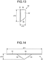
- FIG. 13 is a side view of the member 50 illustrated in FIG. 12 .
- FIG. 14 is a plan view of the member 50 illustrated in FIG. 12 .
- the member 50 is formed of a combination of a wall 51, a wall 52, a wall 53, a wall 54, and a wall 55 planar in shape.
- the wall 51 is rectangular in shape.
- the wall 51 is provided in parallel to a surface 33a of a key block 33.
- the wall 52 and the wall 53 are each trapezoidal in shape.
- the wall 52 and the wall 53 are each provided inclining at an intermediate portion of the wall 51.
- the wall 52 and the wall 53 are each provided in a plane crossing the surface 33a of the key block 33.
- a circumferential edge 52a of the wall 52 and a circumferential edge 53a of the wall 53 are each joined to the intermediate portion of the wall 51, resulting in formation of bends.
- a circumferential edge 52b of the wall 52 and a circumferential edge 53b of the wall 53 are joined together, resulting in formation of a bend.
- the wall 54 and the wall 55 are each triangular in shape.
- the wall 54 is provided covering the opening surrounded by the upper portion of the wall 51, the upper portion of the wall 52, and the upper portion of the wall 53.
- the wall 55 is provided covering the opening surrounded by the lower portion of the wall 51, the lower portion of the wall 52, and the lower portion of the wall 53.
- the wall 52, the wall 53, the wall 54, and the wall 55 each serve as part of formation of a humped shape protruding inward in the radial direction of the case 32 from a surface 33b of the key block 33.
- the wall 52, the wall 53, the wall 54, and the wall 55 each serve as part of formation of a triangular prism.
- the respective normals of the wall 51, the wall 52, the wall 53, the wall 54, and the wall 55 extend in different directions and cross each other.
- the wall 51 has a length d11 approximately the same as the width dk1 of the key block 33.
- the wall 51 has a length d12 shorter than the distance dk2 from the key block 33 to the cutter ring 41.
- the distance d13 from the wall 51 to the joint between the wall 52 and the wall 53 is approximately the same as the thickness dk3 of the key block 33 (refer to FIG. 11 ).
- the wall 51 protrudes outward from the wall 52 and the wall 53.
- such a plurality of members 50 as above is provided around a disc cutter 40.
- two members 50 are provided around a disc cutter 40.
- one member 50 is provided on one side in the axial direction of a cutter ring 41 (direction of the fixed axis AX2) and another member 50 is provided on the other side.
- such a member 50 is attached to a key block 33 by welding.
- the member 50 has a plurality of faces facing in different directions.
- the plurality of faces of the member 50 varies mutually discontinuously.
- the member 50 provided includes a humped shape protruding toward the cutter chamber 30C.
- the humped shape included in the member 50 protrudes from the surface 33b of the key block 33.
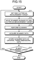
- FIG. 15 is a flowchart of an exemplary processing procedure of a method of measuring the cutter ring 41 of a disc cutter 40 in the criterial state.
- FIG. 16 is a flowchart of an exemplary processing procedure of a method of measuring the cutter ring 41 of a disc cutter 40 in an operation state.
- the processing illustrated in FIG. 15 is performed at least once, resulting in acquisition of criterial three-dimensional data of the disc cutter 40.
- Such criterial three-dimensional data is preferably acquired in response to mounting of a new disc cutter 40 or mounting of a disc cutter 40 on which a new cutter ring is mounted.
- the measurement target setting unit 111 in the measurement controller 110 sets a disc cutter 40 as the measurement target (Step S11). For example, the order of measurement of all disc cutters 40 mounted on the cutterhead 30 is stored in a storage unit not illustrated. In accordance with the stored order, the measurement target setting unit 111 sets the corresponding disc cutter 40 as the measurement target. The measurement target setting unit 111 in the measurement controller 110 controls the drive motor 29 to rotate the cutterhead 30 such that the scanner 65 can measure the disc cutter 40 as the measurement target. The measurement controller 110 proceeds to Step S12.
- the measurement controller 110 moves the scanner 65 on the basis of the disc cutter 40 as the measurement target (Step S12). More particularly, the front-and-back movement control unit 112 in the measurement controller 110 controls the front-and-back movement actuator 62 to adjust the position in the front-and-back direction of the scanner 65 on the basis of the disc cutter 40 as the measurement target. The up-and-down movement control unit 113 in the measurement controller 110 controls the up-and-down movement actuator 64 to adjust the position in the up-and-down direction of the scanner 65 on the basis of the disc cutter 40 as the measurement target. The measurement controller 110 proceeds to Step S13.
- the scanner control unit 114 in the measurement controller 110 controls the scanner 65 to perform three-dimensional measurement of the disc cutter 40 as the measurement target (Step S13).
- the scanner control unit 114 causes the scanner 65 to scan the three-dimensional shape of the disc cutter 40 as the measurement target.
- the scanner control unit 114 measures the three-dimensional shape of the cutter ring 41 in the criterial state together with the three-dimensional shape of the members 50.
- the measurement controller 110 proceeds to Step S14.
- the data acquisition unit 115 in the measurement controller 110 acquires data measured by the scanner 65 in the measurement device 60 (Step S14).
- the measurement controller 110 proceeds to Step S15.
- the data acquisition unit 115 in the measurement controller 110 stores the acquired data as the criterial three-dimensional data of the disc cutter 40 into a storage unit 120 (Step S15).
- the criterial three-dimensional data of the disc cutter 40 includes three-dimensional shape data of the cutter ring 41 and three-dimensional shape data of the members 50 in the criterial state.
- the data acquisition unit 115 stores the acquired criterial three-dimensional data in association with identification information regarding the disc cutter 40 as the measurement target.
- the measurement controller 110 proceeds to Step S16.
- the measurement controller 110 determines whether or not a disc cutter 40 as the next measurement target is present (Step S16). In a case where a disc cutter 40 yet to be measured is present, the measurement controller 110 determines that a disc cutter 40 as the next measurement target is present (Yes in Step S16), and then performs the processing in Step S11 again. In a case where all disc cutters 40 have been measured, the measurement controller 110 determines that no disc cutter 40 as the next measurement target is present (No in Step S16), and then terminates the processing.
- the measurement controller 110 acquires and stores the criterial three-dimensional data of the cutter ring 41 of each disc cutter 40 in the criterial state and the members 50 each provided at the part constant in relative position to the cutter ring 41.
- Step S21, Step S22, and Step S28 are similar in processing to Step S11, Step S12, and Step S16 described above, respectively, and thus the descriptions thereof will be omitted.
- Step S23 the scanner control unit 114 in the measurement controller 110 controls the scanner 65 to perform three-dimensional measurement of the disc cutter 40 as the measurement target.
- the scanner control unit 114 measures the three-dimensional shape of the cutter ring 41 in an operation state together with the three-dimensional shape of the members 50.
- the measurement controller 110 proceeds to Step S24.
- the data acquisition unit 115 in the measurement controller 110 acquires data measured by the scanner 65 in the measurement device 60 (Step S24).
- the measurement controller 110 proceeds to Step S25.
- the data acquisition unit 115 in the measurement controller 110 stores the acquired data as the measurement three-dimensional data of the disc cutter 40 into the storage unit 120 (Step S25).
- the measurement three-dimensional data of the disc cutter 40 includes three-dimensional shape data of the cutter ring 41 and three-dimensional shape data of the members 50 in the operation state.
- the measurement controller 110 proceeds to Step S26.
- the wear-amount calculation unit 116 in the measurement controller 110 reads the criterial three-dimensional data of the disc cutter 40 with reference to the identification information regarding the disc cutter 40, and calculates the wear amount of the cutter ring 41 of the disc cutter 40, on the basis of the criterial three-dimensional data and the measurement three-dimensional data (Step S26).
- the measurement controller 110 collates the criterial three-dimensional data and the measurement three-dimensional data, to calculate the wear amount of the cutter ring 41.
- FIG. 17 is a schematic explanatory view of alignment in measurement. As illustrated in FIG.
- the wear-amount calculation unit 116 performs alignment between the criterial three-dimensional data indicated with broken lines and the measurement three-dimensional data indicated with solid lines, with respective members 50 as the criterion, namely, such that the respective members 50 are superimposed together.
- the difference between the blade edge 44 in the criterial three-dimensional data and the blade edge 44 in the measurement three-dimensional data after alignment corresponds to the wear amount W of the cutter ring 41.
- the measurement controller 110 proceeds to Step S27.
- the wear-amount calculation unit 116 in the measurement controller 110 stores, into the storage unit 120, the calculated wear amount of the cutter ring 41 of the disc cutter 40 in association with the identification information regarding the disc cutter 40 (Step S27).
- the measurement controller 110 proceeds to Step S28.
- the measurement controller 110 determines that a disc cutter 40 as the next measurement target is present (Yes in Step S28), and then performs the processing in Step S21 again. In a case where all disc cutters 40 have been measured, the measurement controller 110 determines that no disc cutter 40 as the next measurement target is present (No in Step S28), and then terminates the processing.
- the wear amount of the cutter ring 41 of each disc cutter 40 in the tunnel boring machine 1 in an operation state is calculated.
- the present embodiment with a member 50 provided at a part constant in relative position to the cutter ring 41 of a disc cutter 40, alignment is performed between the criterial three-dimensional data and the measurement three-dimensional data measured by the measurement device 60. Because the member 50 is located so as not to wear, the member 50 is inhibited from varying in shape between the criterial three-dimensional data and the measurement three-dimensional data. According to the present embodiment, highly accurate alignment can be performed between the criterial three-dimensional data and the measurement three-dimensional data. In this manner, the present embodiment enables highly accurate measurement of the wear amount of the cutter ring 41.
- alignment with the member 50 enables achievement of the targeted accuracy of measurement, regardless of the shape of the member 50. According to the present embodiment, alignment with the member 50 enables achievement of the targeted accuracy of measurement, regardless of the wear amount of the cutter ring 41. According to the present embodiment, alignment with the member 50 enables achievement of the targeted accuracy of measurement, regardless of the angle of measurement.
- the wear amount of the cutter ring 41 can be easily measured.
- the member 50 has a plurality of faces facing in different directions. According to the present embodiment, regardless of the relative position between the measurement device 60 and the member 50 with the cutter ring 41 of the disc cutter 40, geometric features of the member 50 can be detected, resulting in achievement of more accurate detection. According to the present embodiment, regardless of the relative position between the measurement device 60 and the member 50 with the cutter ring 41 of the disc cutter 40, the wear amount of the cutter ring 41 can be measured highly accurately.
- the member 50 is provided closer to the cutter chamber 30C in the tunnel boring machine 1. According to the present embodiment, in excavation of the tunnel boring machine 1, the excavation can be inhibited from being interfered with the member 50, and the member 50 can be inhibited from wearing.
- the member 50 together with the cutter ring 41 is located detectably in the detection area of the measurement device 60.
- the criterial three-dimensional data and the measurement three-dimensional data that indicate the three-dimensional shape of the cutter ring 41 and the member 50 can be easily acquired.
- the member 50 is provided at a key block 33. According to the present embodiment, the member 50 can be located so as not to interfere with replacement of the disc cutter 40.
- the member 50 is attached to the key block 33 by welding. If the member 50 is damaged or deformed, the member 50 can be easily replaced together with the key block 33.
- such a plurality of members 50 is provided around the disc cutter 40. According to the present embodiment, in measurement of the measurement device 60, an improvement can be made in the accuracy of alignment.
- one member 50 is provided on one side in the axial direction of the cutter ring 41 and another member 50 is provided on the other side. According to the present embodiment, regardless of the relative position between the measurement device 60 and the members 50 with the cutter ring 41 of the disc cutter 40, the members 50 can be detected. Thus, the present embodiment enables highly accurate alignment between the criterial three-dimensional data and the measurement three-dimensional data. According to the present embodiment, regardless of the relative position between the measurement device 60 and the members 50 with the cutter ring 41 of the disc cutter 40, more accurate detection can be achieved.
- each member 50 provided includes a humped shape protruding toward the cutter chamber 30C. According to the present embodiment, the accuracy of detection of the members 50 is inhibited from deteriorating due to the influence of clogging, for example, due to excavated muck in excavation.
- the members 50 are each provided replaceably at a key block 33. According to the present embodiment, for example, in a case where any member 50 is damaged, only the member 50 can be easily replaced. According to the present embodiment, the members 50 can be easily mounted on the conventional cutterhead 30.
- Such a member 50 as above may be fixed to a case 32, a retainer 43 (retaining member), or a hub 42 by welding, instead of to a key block 33. In this case, at the time of replacement, the member 50 needs to be detached by cutting.
- FIG. 18 is a front view of an exemplary member 50A.
- FIG. 19 is a side view of the member 50A illustrated in FIG. 18 .
- FIG. 20 is a plan view of the member 50A illustrated in FIG. 18 .
- the member 50A has a wall 51A different in shape from the wall 51 of the member 50, and is smaller than the member 50.
- the wall 51A has a length d21 shorter than the length d11 of the wall 51 of the member 50.
- the wall 51A has a length d22 the same as the length d12 of the wall 51 of the member 50.
- the distance d23 from the wall 51A to the joint between a wall 52A and a wall 53A is the same as the distance d13 of the member 50.
- a circumferential edge 52a of the wall 52 and a circumferential edge 53a of the wall 53 are each joined to an end portion of the wall 51A.
- the wall 51A does not protrude outward from the wall 52 and the wall 53.
- Such a shape of the member 50A can be made smaller than the member 50.
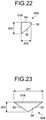
- FIG. 21 is a front view of an exemplary member 50B.
- FIG. 22 is a side view of the member 50B illustrated in FIG. 21 .
- FIG. 23 is a plan view of the member 50B illustrated in FIG. 21 .
- the member 50B is smaller than the member 50A.
- a wall 51B has a length d31 the same as the length d21 of the wall 51A of the member 50A.
- the wall 51B has a length d32 shorter than the length d22 of the wall 51A of the member 50A.
- the distance d33 from the wall 51B to the joint between a wall 52B and a wall 53B is the same as the distance d23 of the member 50A.
- Such a shape of member 50B can be made smaller than the member 50 and the member 50A.
- FIG. 24 is an explanatory graph of differences in the accuracy of measurement from the conventional technique.
- FIG. 25 is an explanatory graph of influence on the accuracy of measurement due to the angle of measurement.
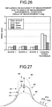
- FIG. 26 is an explanatory graph of influence on the accuracy of measurement due to the angle of measurement.
- Measurement is performed with a variation in the shape of a member 50 for use in alignment. More particularly, measurement with the measurement device 60 with the member 50, the member 50A, and the member 50B described above for alignment and measurement with the conventional technique are performed. "Shape 1" indicates measurement with the member 50, “Shape 2" indicates measurement with the member 50A, “Shape 3” indicates measurement with the member 50B, and "Conventional Technique” indicates measurement with the conventional technique.
- FIG. 27 is a schematic explanatory view of alignment with the conventional technique.
- the conventional technique is a technique in which, without any member for alignment, the wear amount is measured with alignment, for example, based on the shape of a shoulder 41a that the cutter ring 41 of a disc cutter 40 has.
- a broken line indicates three-dimensional data acquired in the criterial state
- a solid line indicates three-dimensional data acquired in an operation state
- a dot-and-dash line indicates three-dimensional data acquired in an operation state with further wear.
- RMSE root mean square error
- Shape 1, Shape 2, and Shape 3 are smaller in RMSE than the conventional technique. Obviously, in each of Shape 1, Shape 2, and Shape 3, the difference in RMSE due to the differences in the wear amount is small. Regardless of the wear amount of the cutter ring 41 of the disc cutter 40, Shape 1, Shape 2, and Shape 3 each fall below the targeted RMSE, resulting in achievement of the targeted accuracy of measurement.
- Shape 1, Shape 2, and Shape 3 are smaller in RMSE than the conventional technique.
- the conventional technique is larger in RMSE at an angle of measurement of 30° than at an angle of measurement of 0°.
- Shape 1, Shape 2, and Shape 3 are slightly larger in RMSE at an angle of measurement of 30° than at an angle of measurement of 0°, but fall below the targeted RMSE. Regardless of the angle of measurement, Shape 1, Shape 2, and Shape 3 fall below the targeted RMSE, resulting in achievement of the targeted accuracy of measurement.
- the member 50, the member 50A, and the member 50B are each formed of a combination of the wall 51, the wall 52, the wall 53, the wall 54, and the wall 55 planar in shape, but this is not the only configuration.
- the member 50, the member 50A, and the member 50B may each be formed of a combination of a plurality of curved faces or may each be formed of a combination of a planar face and a curved face.
- controller 100 and the measurement controller 110 are separately provided, but the present invention is not limited to this.
- the controller 100 and the measurement controller 110 may be integrally provided.
- the scanner 65 is movable forward and backward by the forward-and-backward variable slider 61 and the front-and-back movement actuator 62 and is movable in the up-and-down direction by the upward-and-downward variable slider 63 and the up-and-down movement actuator 64, but moving means are not limited to this.
- the scanner 65 may be mounted on an unmanned flight vehicle, such as a drone.
Landscapes
- Engineering & Computer Science (AREA)
- Mining & Mineral Resources (AREA)
- Geology (AREA)
- Life Sciences & Earth Sciences (AREA)
- Environmental & Geological Engineering (AREA)
- General Life Sciences & Earth Sciences (AREA)
- Geochemistry & Mineralogy (AREA)
- Physics & Mathematics (AREA)
- Aviation & Aerospace Engineering (AREA)
- General Physics & Mathematics (AREA)
- Fluid Mechanics (AREA)
- Mechanical Engineering (AREA)
- Excavating Of Shafts Or Tunnels (AREA)
- Length Measuring Devices With Unspecified Measuring Means (AREA)
Abstract
Description
- The present invention relates to a tunnel boring machine, a measurement method, and a measurement system. Background
- Regarding a tunnel boring machine, the wear amount of a disc cutter mounted on a cutterhead is measured regularly. Known has been a technique of showing the condition of the leading end portion of a tunnel boring machine on an image display device by use of an image sensor (for example, refer to Patent Literature 1). As a technique of measuring the shape of an object in a noncontact manner, known has been a three-dimensional shape measurement device.
- Patent Literature 1:
JP H04-110642 A - In a case where the wear amount of a disc cutter is measured with a three-dimensional shape measurement device, for example, three-dimensional data of the disc cutter in the criterial state, such as just after attachment or before operation, and three-dimensional data of the disc cutter in an operation state are superimposed together on the basis of features of the shape of the disc cutter, and then the wear amount is measured. However, a change in the shape of the disc cutter due to wearing is likely to cause a larger error in superimposition of such pieces of three-dimensional data.
- An object of the present invention is to achieve highly accurate measurement of the wear amount of a disc cutter.
- According to an aspect of the present invention, a tunnel boring machine comprises: a disc cutter including a cutter ring; and a member for use in measurement of a wear amount of the cutter ring with a three-dimensional shape measurement device, wherein the member is provided at a part constant in relative position to the cutter ring. Advantageous Effects of Invention
- According to the present invention, highly accurate measurement of the wear amount of a disc cutter can be achieved.
-
-
FIG. 1 is a side view of the configuration of a tunnel boring machine according to the present embodiment. -
FIG. 2 is a schematic perspective view of a cutterhead of the tunnel boring machine according to the present embodiment. -
FIG. 3 is a side view of a disc cutter mounted on a case. -
FIG. 4 is a front view of the disc cutter mounted on the case. -
FIG. 5 is a schematic explanatory view of detachment of the disc cutter. -
FIG. 6 is a schematic view of the configuration of a measurement device. -
FIG. 7 is a schematic explanatory view of a state where the measurement device measures a disc cutter. -
FIG. 8 is a block diagram of the configuration of a controller. -
FIG. 9 is a block diagram of a computer system according to the present embodiment. -
FIG. 10 is a front view of members each provided at a key block by welding, in a first embodiment of the present invention. -
FIG. 11 is a side view of a case on which a disc cutter is mounted with the key blocks each provided with the member, in the first embodiment of the present invention. -
FIG. 12 is a front view of an exemplary member. -
FIG. 13 is a side view of the member illustrated inFIG. 12 . -
FIG. 14 is a plan view of the member illustrated inFIG. 12 . -
FIG. 15 is a flowchart of an exemplary processing procedure of a method of measuring the cutter ring of a disc cutter in the criterial state. -
FIG. 16 is a flowchart of an exemplary processing procedure of a method of measuring the cutter ring of a disc cutter in an operation state. -
FIG. 17 is a schematic explanatory view of alignment in measurement. -
FIG. 18 is a front view of an exemplary member. -
FIG. 19 is a side view of the member illustrated inFIG. 18 . -
FIG. 20 is a plan view of the member illustrated inFIG. 18 . -
FIG. 21 is a front view of an exemplary member. -
FIG. 22 is a side view of the member illustrated inFIG. 21 . -
FIG. 23 is a plan view of the member illustrated inFIG. 21 . -
FIG. 24 is an explanatory graph of differences in the accuracy of measurement from a conventional technique. -
FIG. 25 is an explanatory graph of influence on the accuracy of measurement due to the angle of measurement. -
FIG. 26 is an explanatory graph of influence on the accuracy of measurement due to the angle of measurement. -
FIG. 27 is a schematic explanatory view of alignment with the conventional technique. - Embodiments of the present invention will be described below with reference to the accompanying drawings. However, the present invention is not limited to the embodiments. The constituent elements in the following embodiments can be appropriately combined. In some cases, some of the constituent elements are not necessarily used.
-
FIG. 1 is a side view of the configuration of atunnel boring machine 1 according to the present embodiment.FIG. 2 is a schematic perspective view of acutterhead 30 of the tunnelboring machine 1 according to the present embodiment. For example, thetunnel boring machine 1 excavates rock in construction of an underground structure, such as a tunnel or a system for supplying water. The tunnelboring machine 1 includes amain body 10 and thecutterhead 30 that is provided on the front side of themain body 10 and excavates rock. As illustrated inFIGS. 1 and2 , thecutterhead 30 is domed in shape and internally has acutter chamber 30C serving as a space for taking in excavated muck generated due to excavation. - The
main body 10 includes amain beam 14 extending in the front-and-back direction and acutterhead support 22 provided at the front end of themain beam 14. Thecutterhead 30 is coupled rotatably to thecutterhead support 22 through abearing 23. Thecutterhead support 22 of themain body 10 has an upper portion provided with aroof support 11, side portions each provided with aside support 12, and a lower portion provided with avertical support 13. As illustrated inFIG. 2 , theroof support 11, the side supports 12, and thevertical support 13 are provided in a cylindrical shape such that the respective outer circumferences thereof are along the sectional shape for excavation. - Inside the
main body 10, provided are agripper 15 to be pressed against the wall of a tunnel and athrust jack 16 variable in length along themain beam 14. The end portion on the front side in the axial direction of thethrust jack 16 is attached on the front side of themain beam 14 and the end portion on the back side thereof is attached to thegripper 15. Thethrust jack 16 is provided variably in length in the front-and-back direction. The tunnelboring machine 1 generates a thrust force with a variation in the length of thethrust jack 16. Thetunnel boring machine 1 presses thegripper 15 against the wall of the tunnel, to acquire a thrust reaction force. - Inside the
main body 10, provided are abelt conveyor 20 extending in the front-and-back direction, achute hopper 21 provided at the upper portion on the front side of thebelt conveyor 20, thecutterhead support 22 provided at the end portion on the front side of themain beam 14, and adrive motor 29. Thebelt conveyor 20 conveys excavated muck generated due to excavation, backward. Thebelt conveyor 20 is provided inside themain beam 14 tubular in shape and penetrates through thecutterhead support 22 such that the leading end thereof is located in thecutter chamber 30C. Thechute hopper 21 is open in thecutter chamber 30C and guides, to thebelt conveyor 20, excavated muck scooped in bybuckets 39 of thecutterhead 30. Thecutterhead support 22 supports thecutterhead 30 rotatably around the rotation axis AX1 thereof. Thecutterhead support 22 is provided with thedrive motor 29 for rotating thecutterhead 30. Thedrive motor 29 serves as a hydraulic motor or an electric motor. - The
cutterhead support 22 to which thecutterhead 30 is connected through thebearing 23 is provided with thedrive motor 29. Thecutterhead 30 rotates around the rotation axis AX1 due to thedrive motor 29. Due to a variation in the length of thethrust jack 16, thecutterhead 30 moves in the front-and-back direction with respect to thegripper 15. Thecutterhead 30 has a plurality ofdisc cutters 40 mounted thereon. Thecutterhead 30 is provided ahead of themain body 10. Thecutterhead 30 is provided with a plurality ofcylindrical cases 32 each housing and retaining adisc cutter 40. That is, thecases 32 provided at thecutterhead 30 are identical in position to thedisc cutters 40 provided at thecutterhead 30. - A
disc cutter 40 will be described withFIGS. 3 and4 .FIG. 3 is a side view of thedisc cutter 40.FIG. 4 is the front view of thedisc cutter 40. Thedisc cutter 40 is supported rotatably to thecutterhead 30. Thedisc cutter 40 is provided at thecutterhead 30 such that the rotation axis thereof (fixed axis AX2 to be described below) intersects with the rotation axis AX1 of thecutterhead 30. Thedisc cutter 40 rotates as thedisc cutter 40 is pressed against the excavation face of the tunnel, so that the rock is crushed. More particularly, with thecutterhead 30 rotating, application of a forward thrust force to themain body 10 and thecutterhead 30 causes thedisc cutter 40 to rotate in contact with the rock under pressure. Rotation of thedisc cutter 40 in contact with the rock under pressure causes rock crushing and rock cracking at the contact between ablade edge 44 of thedisc cutter 40 and the rock. A crack occurring in the rock links with another crack adjacent thereto and then adjacent crushing occurs, resulting in excavation of the rock. Excavated muck generated in excavation of the rock is scooped in thechute hopper 21 open in thecutter chamber 30C through thebuckets 39 provided at thecutterhead 30 and then is conveyed backward by a belt conveyor 17. - The
disc cutter 40 includes acutter ring 41, ahub 42 supporting thecutter ring 41 unrotatably, a shaft (not illustrated) supporting thehub 42 rotatably through a bearing (not illustrated), and a pair ofretainers 43 retaining the shaft with thehub 42 interposed therebetween in the axial direction. The central line of the shaft retained by the pair ofretainers 43 is illustrated as the fixed axis AX2 inFIG. 3 . That is, thecutter ring 41 and thehub 42 are supported rotatably through the bearing not illustrated on the fixed axis AX2. Thecutter ring 41 and thehub 42 are rotatable integrally. The pair ofretainers 43 serves as a retaining member that sandwiches the cutter ring in the axial direction and retains the cutter ring rotatably. Thecutter ring 41 rotates as thecutter ring 41 is pressed against the excavation face of the tunnel, so that the excavation face is excavated. - The
cutter ring 41 has ablade edge 44. Theblade edge 44 protrudes forward and backward from the case 32 (refer toFIGS. 3 and11 ). Theblade edge 44 is exposed from the front face and back face of thecase 32. Theblade edge 44 protrudes forward from thefront face 31 of thecutterhead 30. - As illustrated in
FIGS. 3 and4 , thedisc cutter 40 is detachably housed in thecase 32 provided at thecutterhead 30. Inside thecase 32, provided is a bearing face that receives the press reaction force of thecutter ring 41 to the excavation face. The pair ofretainers 43 of thedisc cutter 40 is fixed to the bearing face. Key blocks 33 are used for positioning of thedisc cutter 40 to thecase 32, namely, for positioning of thedisc cutter 40 to thecutterhead 30. The key blocks 33 are each detachably provided, from the cutter chamber side, to thecase 32. As illustrated inFIG. 3 , with thedisc cutter 40 having theretainers 43 abutting on the bearing face of thecase 32, the key blocks 33 are provided from the cutter chamber side. Eachkey block 33 and thecorresponding retainer 43 are fastened through thecase 32 withbolts 34, so that thedisc cutter 40 is fixed to thecutterhead 30. As described above, the bearing face of thecase 32 functions to support the press reaction force of thedisc cutter 40 to the excavation face, and the key blocks 33 in cooperation with thebolts 34 function as a positioning member that positions thedisc cutter 40 to thecutterhead 30 and restricts movement thereof. - A method of replacing a
disc cutter 40 will be described in detail withFIG. 5. FIG. 5 is a schematic explanatory view of detachment of thedisc cutter 40. Thedisc cutter 40 is restricted by the key blocks 33 in detachment from thecase 32 and in movement along the circumferential direction of thecase 32. As illustrated inFIG. 5(a) , thebolts 34 fixing the key blocks 33 to thecase 32 are detached. As illustrated inFIG. 5(b) , the key blocks 33 are detached from thecase 32. The detachment of the key blocks 33 releases the restriction of thedisc cutter 40. As illustrated inFIG. 5(c) , thedisc cutter 40 housed in thecase 32 is rotated by 90° in the circumferential direction of thecase 32. As illustrated inFIG. 5(d) , thedisc cutter 40 is detached from thecase 32. - In a case where a
new disc cutter 40 is housed into thecase 32, thedisc cutter 40 is inserted into thecase 32, inversely to the process inFIG. 5(d) . Inversely to the process inFIG. 5(c) , thedisc cutter 40 inserted in thecase 32 is rotated by 90°, inversely to the rotation in detachment, in the circumferential direction of thecase 32. Inversely to the process inFIG. 5(b) , the key blocks 33 are attached to thecase 32. Inversely to the process inFIG. 5(a) , the key blocks 33 are fixed to thecase 32 with thebolts 34. In this manner, fixed is thedisc cutter 40 restricted by the key blocks 33 in detachment from thecase 32 and in movement along the circumferential direction of thecase 32. - An excavation method by such a
tunnel boring machine 1 as above will be described. In thetunnel boring machine 1, due to thedrive motor 29, thecutterhead 30 rotates with respect to themain body 10. Eachdisc cutter 40 attached to thecutterhead 30 rotates as eachdisc cutter 40 is pressed against the excavation face of the tunnel, so that the rock is crushed. Excavated muck produced in excavation of the rock is scooped into themain body 10 by thebuckets 39 and then is conveyed backward by the belt conveyor 17. Because eachdisc cutter 40 wears due to excavation, for example, before the start of daily work or every predetermined period, the wear amount of thecutter ring 41 of eachdisc cutter 40 is measured. - A
measurement device 60 for use in measurement of the wear amount of thecutter ring 41 of adisc cutter 40, in thetunnel boring machine 1, will be described withFIGS. 6 and 7. FIG. 6 is a schematic view of the configuration of themeasurement device 60.FIG. 7 is a schematic explanatory view of a state where themeasurement device 60 measures adisc cutter 40. Themeasurement device 60 is provided closer to thecutter chamber 30C (refer toFIG. 1 ) in thetunnel boring machine 1. Themeasurement device 60 includes a forward-and-backwardvariable slider 61 variable forward and backward in length, a front-and-backmovement actuator 62 that slides ascanner 65 along the forward-and-backwardvariable slider 61, an upward-and-downwardvariable slider 63 variable upward and downward in length, an up-and-downmovement actuator 64 that slides thescanner 65 along the upward-and-downwardvariable slider 63, thescanner 65, and acase 69 that houses the forward-and-backwardvariable slider 61, the front-and-backmovement actuator 62, the upward-and-downwardvariable slider 63, the up-and-downmovement actuator 64, and thescanner 65. The front-and-backmovement actuator 62 varies the forward-and-backwardvariable slider 61 in length, to slide thescanner 65 forward and backward. The up-and-downmovement actuator 64 varies the upward-and-downwardvariable slider 63 in length, to slide thescanner 65 upward and downward. - The
scanner 65 serves as a 3D scanner, detects a target, and outputs three-dimensional data indicating the three-dimensional shape of the target to adata acquisition unit 115 in ameasurement controller 110. More particularly, thescanner 65 is capable of detecting the three-dimensional shape of thecutter ring 41 of adisc cutter 40 and amember 50 to be described below (refer toFIG. 10 ). For example, thescanner 65 detects criterial three-dimensional data indicating the three-dimensional shape of acutter ring 41 and amember 50 in the criterial state, such as just after attachment or before operation of adisc cutter 40 on which anew cutter ring 41 is mounted (namely, thecutter ring 41 has not worn yet) and measurement three-dimensional data indicating the three-dimensional shape of thecutter ring 41 and themember 50 in an operation state (namely, thecutter ring 41 is assumed to have worn to a certain extent). Thescanner 65 outputs the detected criterial three-dimensional data and measurement three-dimensional data to thedata acquisition unit 115 in themeasurement controller 110. - The
scanner 65 is movable forward and backward by the forward-and-backwardvariable slider 61 and the front-and-backmovement actuator 62 and is movable in the up-and-down direction by the upward-and-downwardvariable slider 63 and the up-and-downmovement actuator 64. - The
scanner 65 adjustable in tilt angle is provided at the upward-and-downwardvariable slider 63. Thescanner 65 is capable of adjusting the angle of measurement to thecutter ring 41 of adisc cutter 40. The angle of measurement corresponds to the angle between the central line C1 of theblade edge 44 of thecutter ring 41 and the central line C2 of the optical axis of thescanner 65. - For example, the
case 69 is provided at thecutterhead support 22. With themeasurement device 60 in non-measurement, the forward-and-backwardvariable slider 61, the front-and-backmovement actuator 62, the upward-and-downwardvariable slider 63, the up-and-downmovement actuator 64, and thescanner 65 are housed in thecase 69. In response to measurement of themeasurement device 60, the forward-and-backwardvariable slider 61, the front-and-backmovement actuator 62, the upward-and-downwardvariable slider 63, the up-and-downmovement actuator 64, and thescanner 65 are developed from thecase 69. - A
controller 100 will be described withFIG. 8. FIG. 8 is a block diagram of the configuration of thecontroller 100. For example, thetunnel boring machine 1 is controlled by thecontroller 100. For example, on the basis of operation information input through an operation board not illustrated or operating information input through an excavation management system not illustrated, thecontroller 100 actuates thetunnel boring machine 1. A drive-motor control unit 101 in thecontroller 100 controls thedrive motor 29 to rotate or stop rotating. - As illustrated in
FIG. 8 , for example, the front-and-backmovement actuator 62, the up-and-downmovement actuator 64, and thescanner 65 in themeasurement device 60 are controlled by themeasurement controller 110. A measurementtarget setting unit 111 in themeasurement controller 110 controls thedrive motor 29 to rotate thecutterhead 30 such that thescanner 65 can measure adisc cutter 40 as the measurement target. A front-and-backmovement control unit 112 in themeasurement controller 110 controls the front-and-backmovement actuator 62 to adjust the position in the front-and-back direction of thescanner 65 on the basis of thedisc cutter 40 as the measurement target. An up-and-downmovement control unit 113 in themeasurement controller 110 controls the up-and-downmovement actuator 64 to adjust the position in the up-and-down direction of thescanner 65 on the basis of thedisc cutter 40 as the measurement target. Ascanner control unit 114 in themeasurement controller 110 controls thescanner 65 to perform three-dimensional measurement. Thedata acquisition unit 115 in themeasurement controller 110 acquires three-dimensional data from thescanner 65. A wear-amount calculation unit 116 in themeasurement controller 110 calculates the wear amount of thecutter ring 41 of thedisc cutter 40, on the basis of the acquired three-dimensional data. - A
computer system 1000 will be described withFIG. 9. FIG. 9 is a block diagram of thecomputer system 1000 according to the present embodiment. Thecontroller 100 described above includes thecomputer system 1000. Thecomputer system 1000 includes aprocessor 1001 like a central processing unit (CPU), amain memory 1002 including a nonvolatile memory like a read only memory (ROM) and a volatile memory like a random access memory (RAM), astorage 1003, and aninterface 1004 including an input/output circuit. The function of thecontroller 100 and the function of themeasurement controller 110, described above, are stored as a program in thestorage 1003. Theprocessor 1001 reads the program from thestorage 1003, develops the program in themain memory 1002, and performs the processing described above, in accordance with the program. Note that the program may be distributed to thecomputer system 1000 through a network. - A
member 50 will be described withFIGS. 10 and11 .FIG. 10 is a front view ofmembers 50 each provided at a key block by welding, in a first embodiment of the present invention.FIG. 11 is a side view of acase 32 on which adisc cutter 40 is mounted with the key blocks 33 each provided with themember 50, in the first embodiment of the present invention. Themembers 50 are used in measurement of the wear amount of thecutter ring 41 of thedisc cutter 40 with the three-dimensional shape measurement device (hereinafter, referred to as the "measurement device") 60. More particularly, themembers 50 are used in alignment in measurement with themeasurement device 60. Themembers 50 together with thecutter ring 41 are located detectably in the detection area of themeasurement device 60. Thus, in measurement with themeasurement device 60, themembers 50 are detected together with thecutter ring 41. - The
members 50 are each located so as to be less likely to wear in excavation of thetunnel boring machine 1 and so as not to interfere with excavation and replacement of thedisc cutter 40. Themembers 50 are each provided at a part constant in relative position to thecutter ring 41 of thedisc cutter 40. The constant relative position means that the positional relationship between thecutter ring 41 and eachmember 50 does not vary between a state just after attachment or before operation of thedisc cutter 40 and the state of thedisc cutter 40 in operation. Themembers 50 are provided near thecutter ring 41. In the present embodiment, themembers 50 are provided at the key blocks 33 that restrict movement of thedisc cutter 40 along the circumferential direction of thecase 32. - The
members 50 are provided closer to thecutter chamber 30C in thetunnel boring machine 1. - An exemplary shape of
member 50 will be described withFIGS. 12 to 14 .FIG. 12 is a front view of anexemplary member 50.FIG. 13 is a side view of themember 50 illustrated inFIG. 12 .FIG. 14 is a plan view of themember 50 illustrated inFIG. 12 . Themember 50 is formed of a combination of awall 51, awall 52, awall 53, awall 54, and awall 55 planar in shape. Thewall 51 is rectangular in shape. Thewall 51 is provided in parallel to asurface 33a of akey block 33. Thewall 52 and thewall 53 are each trapezoidal in shape. Thewall 52 and thewall 53 are each provided inclining at an intermediate portion of thewall 51. Thewall 52 and thewall 53 are each provided in a plane crossing thesurface 33a of thekey block 33. Acircumferential edge 52a of thewall 52 and acircumferential edge 53a of thewall 53 are each joined to the intermediate portion of thewall 51, resulting in formation of bends. Acircumferential edge 52b of thewall 52 and acircumferential edge 53b of thewall 53 are joined together, resulting in formation of a bend. Thewall 54 and thewall 55 are each triangular in shape. Thewall 54 is provided covering the opening surrounded by the upper portion of thewall 51, the upper portion of thewall 52, and the upper portion of thewall 53. Thewall 55 is provided covering the opening surrounded by the lower portion of thewall 51, the lower portion of thewall 52, and the lower portion of thewall 53. Thewall 52, thewall 53, thewall 54, and thewall 55 each serve as part of formation of a humped shape protruding inward in the radial direction of thecase 32 from asurface 33b of thekey block 33. Thewall 52, thewall 53, thewall 54, and thewall 55 each serve as part of formation of a triangular prism. - The respective normals of the
wall 51, thewall 52, thewall 53, thewall 54, and thewall 55 extend in different directions and cross each other. - The
wall 51 has a length d11 approximately the same as the width dk1 of thekey block 33. Thewall 51 has a length d12 shorter than the distance dk2 from thekey block 33 to thecutter ring 41. The distance d13 from thewall 51 to the joint between thewall 52 and thewall 53 is approximately the same as the thickness dk3 of the key block 33 (refer toFIG. 11 ). Thewall 51 protrudes outward from thewall 52 and thewall 53. - Preferably, such a plurality of
members 50 as above is provided around adisc cutter 40. In the present embodiment, twomembers 50 are provided around adisc cutter 40. - Preferably, as in the present embodiment, one
member 50 is provided on one side in the axial direction of a cutter ring 41 (direction of the fixed axis AX2) and anothermember 50 is provided on the other side. - In the present embodiment, such a
member 50 is attached to akey block 33 by welding. - The
member 50 has a plurality of faces facing in different directions. The plurality of faces of themember 50 varies mutually discontinuously. - The
member 50 provided includes a humped shape protruding toward thecutter chamber 30C. In the present embodiment, the humped shape included in themember 50 protrudes from thesurface 33b of thekey block 33. - Next, a method/processing of measuring the wear amount of the
cutter ring 41 of adisc cutter 40 with themeasurement device 60 in thetunnel boring machine 1 includingdisc cutters 40 will be described.FIG. 15 is a flowchart of an exemplary processing procedure of a method of measuring thecutter ring 41 of adisc cutter 40 in the criterial state.FIG. 16 is a flowchart of an exemplary processing procedure of a method of measuring thecutter ring 41 of adisc cutter 40 in an operation state. Before measurement of the wear amount of thecutter ring 41 of adisc cutter 40 in an operation state in thetunnel boring machine 1, the processing illustrated inFIG. 15 is performed at least once, resulting in acquisition of criterial three-dimensional data of thedisc cutter 40. Such criterial three-dimensional data is preferably acquired in response to mounting of anew disc cutter 40 or mounting of adisc cutter 40 on which a new cutter ring is mounted. - The measurement
target setting unit 111 in themeasurement controller 110 sets adisc cutter 40 as the measurement target (Step S11). For example, the order of measurement of alldisc cutters 40 mounted on thecutterhead 30 is stored in a storage unit not illustrated. In accordance with the stored order, the measurementtarget setting unit 111 sets thecorresponding disc cutter 40 as the measurement target. The measurementtarget setting unit 111 in themeasurement controller 110 controls thedrive motor 29 to rotate thecutterhead 30 such that thescanner 65 can measure thedisc cutter 40 as the measurement target. Themeasurement controller 110 proceeds to Step S12. - The
measurement controller 110 moves thescanner 65 on the basis of thedisc cutter 40 as the measurement target (Step S12). More particularly, the front-and-backmovement control unit 112 in themeasurement controller 110 controls the front-and-backmovement actuator 62 to adjust the position in the front-and-back direction of thescanner 65 on the basis of thedisc cutter 40 as the measurement target. The up-and-downmovement control unit 113 in themeasurement controller 110 controls the up-and-downmovement actuator 64 to adjust the position in the up-and-down direction of thescanner 65 on the basis of thedisc cutter 40 as the measurement target. Themeasurement controller 110 proceeds to Step S13. - The
scanner control unit 114 in themeasurement controller 110 controls thescanner 65 to perform three-dimensional measurement of thedisc cutter 40 as the measurement target (Step S13). Thescanner control unit 114 causes thescanner 65 to scan the three-dimensional shape of thedisc cutter 40 as the measurement target. Thescanner control unit 114 measures the three-dimensional shape of thecutter ring 41 in the criterial state together with the three-dimensional shape of themembers 50. Themeasurement controller 110 proceeds to Step S14. - The
data acquisition unit 115 in themeasurement controller 110 acquires data measured by thescanner 65 in the measurement device 60 (Step S14). Themeasurement controller 110 proceeds to Step S15. - The
data acquisition unit 115 in themeasurement controller 110 stores the acquired data as the criterial three-dimensional data of thedisc cutter 40 into a storage unit 120 (Step S15). The criterial three-dimensional data of thedisc cutter 40 includes three-dimensional shape data of thecutter ring 41 and three-dimensional shape data of themembers 50 in the criterial state. Thedata acquisition unit 115 stores the acquired criterial three-dimensional data in association with identification information regarding thedisc cutter 40 as the measurement target. Themeasurement controller 110 proceeds to Step S16. - The
measurement controller 110 determines whether or not adisc cutter 40 as the next measurement target is present (Step S16). In a case where adisc cutter 40 yet to be measured is present, themeasurement controller 110 determines that adisc cutter 40 as the next measurement target is present (Yes in Step S16), and then performs the processing in Step S11 again. In a case where alldisc cutters 40 have been measured, themeasurement controller 110 determines that nodisc cutter 40 as the next measurement target is present (No in Step S16), and then terminates the processing. - In this manner, with the
measurement device 60, themeasurement controller 110 acquires and stores the criterial three-dimensional data of thecutter ring 41 of eachdisc cutter 40 in the criterial state and themembers 50 each provided at the part constant in relative position to thecutter ring 41. - After acquisition of the criterial three-dimensional data, the processing illustrated in
FIG. 16 is performed, for example, before the start of daily work or every predetermined period, resulting in measurement of the wear amount of thecutter ring 41 of eachdisc cutter 40 in thetunnel boring machine 1. Step S21, Step S22, and Step S28 are similar in processing to Step S11, Step S12, and Step S16 described above, respectively, and thus the descriptions thereof will be omitted. - In Step S23, the
scanner control unit 114 in themeasurement controller 110 controls thescanner 65 to perform three-dimensional measurement of thedisc cutter 40 as the measurement target. Thescanner control unit 114 measures the three-dimensional shape of thecutter ring 41 in an operation state together with the three-dimensional shape of themembers 50. Themeasurement controller 110 proceeds to Step S24. - The
data acquisition unit 115 in themeasurement controller 110 acquires data measured by thescanner 65 in the measurement device 60 (Step S24). Themeasurement controller 110 proceeds to Step S25. - The
data acquisition unit 115 in themeasurement controller 110 stores the acquired data as the measurement three-dimensional data of thedisc cutter 40 into the storage unit 120 (Step S25). The measurement three-dimensional data of thedisc cutter 40 includes three-dimensional shape data of thecutter ring 41 and three-dimensional shape data of themembers 50 in the operation state. Themeasurement controller 110 proceeds to Step S26. - The wear-
amount calculation unit 116 in themeasurement controller 110 reads the criterial three-dimensional data of thedisc cutter 40 with reference to the identification information regarding thedisc cutter 40, and calculates the wear amount of thecutter ring 41 of thedisc cutter 40, on the basis of the criterial three-dimensional data and the measurement three-dimensional data (Step S26). Themeasurement controller 110 collates the criterial three-dimensional data and the measurement three-dimensional data, to calculate the wear amount of thecutter ring 41.FIG. 17 is a schematic explanatory view of alignment in measurement. As illustrated inFIG. 17(a) , the wear-amount calculation unit 116 performs alignment between the criterial three-dimensional data indicated with broken lines and the measurement three-dimensional data indicated with solid lines, withrespective members 50 as the criterion, namely, such that therespective members 50 are superimposed together. As illustrated inFIG. 17(b) , the difference between theblade edge 44 in the criterial three-dimensional data and theblade edge 44 in the measurement three-dimensional data after alignment corresponds to the wear amount W of thecutter ring 41. Themeasurement controller 110 proceeds to Step S27. - The wear-
amount calculation unit 116 in themeasurement controller 110 stores, into thestorage unit 120, the calculated wear amount of thecutter ring 41 of thedisc cutter 40 in association with the identification information regarding the disc cutter 40 (Step S27). Themeasurement controller 110 proceeds to Step S28. - In a case where a
disc cutter 40 yet to be measured is present, themeasurement controller 110 determines that adisc cutter 40 as the next measurement target is present (Yes in Step S28), and then performs the processing in Step S21 again. In a case where alldisc cutters 40 have been measured, themeasurement controller 110 determines that nodisc cutter 40 as the next measurement target is present (No in Step S28), and then terminates the processing. - Due to such processing as above, the wear amount of the
cutter ring 41 of eachdisc cutter 40 in thetunnel boring machine 1 in an operation state is calculated. - In the present embodiment, with a
member 50 provided at a part constant in relative position to thecutter ring 41 of adisc cutter 40, alignment is performed between the criterial three-dimensional data and the measurement three-dimensional data measured by themeasurement device 60. Because themember 50 is located so as not to wear, themember 50 is inhibited from varying in shape between the criterial three-dimensional data and the measurement three-dimensional data. According to the present embodiment, highly accurate alignment can be performed between the criterial three-dimensional data and the measurement three-dimensional data. In this manner, the present embodiment enables highly accurate measurement of the wear amount of thecutter ring 41. - According to the present embodiment, alignment with the
member 50 enables achievement of the targeted accuracy of measurement, regardless of the shape of themember 50. According to the present embodiment, alignment with themember 50 enables achievement of the targeted accuracy of measurement, regardless of the wear amount of thecutter ring 41. According to the present embodiment, alignment with themember 50 enables achievement of the targeted accuracy of measurement, regardless of the angle of measurement. - In the present embodiment, with the
member 50, alignment is performed between the criterial three-dimensional data and the measurement three-dimensional data. Thus, highly accurate acquisition of the coordinates and posture of thescanner 65 in themeasurement device 60 need not be obtained. According to the present embodiment, the wear amount of thecutter ring 41 can be easily measured. - In the present embodiment, the
member 50 has a plurality of faces facing in different directions. According to the present embodiment, regardless of the relative position between themeasurement device 60 and themember 50 with thecutter ring 41 of thedisc cutter 40, geometric features of themember 50 can be detected, resulting in achievement of more accurate detection. According to the present embodiment, regardless of the relative position between themeasurement device 60 and themember 50 with thecutter ring 41 of thedisc cutter 40, the wear amount of thecutter ring 41 can be measured highly accurately. - In the present embodiment, the
member 50 is provided closer to thecutter chamber 30C in thetunnel boring machine 1. According to the present embodiment, in excavation of thetunnel boring machine 1, the excavation can be inhibited from being interfered with themember 50, and themember 50 can be inhibited from wearing. - In the present embodiment, the
member 50 together with thecutter ring 41 is located detectably in the detection area of themeasurement device 60. According to the present embodiment, the criterial three-dimensional data and the measurement three-dimensional data that indicate the three-dimensional shape of thecutter ring 41 and themember 50 can be easily acquired. - In the present embodiment, the
member 50 is provided at akey block 33. According to the present embodiment, themember 50 can be located so as not to interfere with replacement of thedisc cutter 40. - In the present embodiment, the
member 50 is attached to thekey block 33 by welding. If themember 50 is damaged or deformed, themember 50 can be easily replaced together with thekey block 33. - In the present embodiment, such a plurality of
members 50 is provided around thedisc cutter 40. According to the present embodiment, in measurement of themeasurement device 60, an improvement can be made in the accuracy of alignment. - In the present embodiment, one
member 50 is provided on one side in the axial direction of thecutter ring 41 and anothermember 50 is provided on the other side. According to the present embodiment, regardless of the relative position between themeasurement device 60 and themembers 50 with thecutter ring 41 of thedisc cutter 40, themembers 50 can be detected. Thus, the present embodiment enables highly accurate alignment between the criterial three-dimensional data and the measurement three-dimensional data. According to the present embodiment, regardless of the relative position between themeasurement device 60 and themembers 50 with thecutter ring 41 of thedisc cutter 40, more accurate detection can be achieved. - In the present embodiment, each
member 50 provided includes a humped shape protruding toward thecutter chamber 30C. According to the present embodiment, the accuracy of detection of themembers 50 is inhibited from deteriorating due to the influence of clogging, for example, due to excavated muck in excavation. - In the present embodiment, the
members 50 are each provided replaceably at akey block 33. According to the present embodiment, for example, in a case where anymember 50 is damaged, only themember 50 can be easily replaced. According to the present embodiment, themembers 50 can be easily mounted on theconventional cutterhead 30. - Such a
member 50 as above may be fixed to acase 32, a retainer 43 (retaining member), or ahub 42 by welding, instead of to akey block 33. In this case, at the time of replacement, themember 50 needs to be detached by cutting. - An exemplary shape of a
member 50A will be described withFIGS. 18 to 20 .FIG. 18 is a front view of anexemplary member 50A.FIG. 19 is a side view of themember 50A illustrated inFIG. 18 .FIG. 20 is a plan view of themember 50A illustrated inFIG. 18 . Themember 50A has awall 51A different in shape from thewall 51 of themember 50, and is smaller than themember 50. Thewall 51A has a length d21 shorter than the length d11 of thewall 51 of themember 50. Thewall 51A has a length d22 the same as the length d12 of thewall 51 of themember 50. The distance d23 from thewall 51A to the joint between a wall 52A and a wall 53A is the same as the distance d13 of themember 50. Acircumferential edge 52a of thewall 52 and acircumferential edge 53a of thewall 53 are each joined to an end portion of thewall 51A. Thewall 51A does not protrude outward from thewall 52 and thewall 53. Such a shape of themember 50A can be made smaller than themember 50. - An exemplary shape of a
member 50B will be described withFIGS. 21 to 23 .FIG. 21 is a front view of anexemplary member 50B.FIG. 22 is a side view of themember 50B illustrated inFIG. 21 .FIG. 23 is a plan view of themember 50B illustrated inFIG. 21 . Themember 50B is smaller than themember 50A. Awall 51B has a length d31 the same as the length d21 of thewall 51A of themember 50A. Thewall 51B has a length d32 shorter than the length d22 of thewall 51A of themember 50A. The distance d33 from thewall 51B to the joint between a wall 52B and a wall 53B is the same as the distance d23 of themember 50A. Such a shape ofmember 50B can be made smaller than themember 50 and themember 50A. - Here, measurement with the
measurement device 60 and measurement with a conventional technique are evaluated in the accuracy of measurement.FIG. 24 is an explanatory graph of differences in the accuracy of measurement from the conventional technique.FIG. 25 is an explanatory graph of influence on the accuracy of measurement due to the angle of measurement.FIG. 26 is an explanatory graph of influence on the accuracy of measurement due to the angle of measurement. With a combination of the following three conditions, measurement was performed ten times in each condition. - (Condition 1) Measurement is performed with a variation in the shape of a
member 50 for use in alignment. More particularly, measurement with themeasurement device 60 with themember 50, themember 50A, and themember 50B described above for alignment and measurement with the conventional technique are performed. "Shape 1" indicates measurement with themember 50, "Shape 2" indicates measurement with themember 50A, "Shape 3" indicates measurement with themember 50B, and "Conventional Technique" indicates measurement with the conventional technique. - Here, measurement with the conventional technique will be described with
FIG. 27. FIG. 27 is a schematic explanatory view of alignment with the conventional technique. The conventional technique is a technique in which, without any member for alignment, the wear amount is measured with alignment, for example, based on the shape of ashoulder 41a that thecutter ring 41 of adisc cutter 40 has. A broken line indicates three-dimensional data acquired in the criterial state, a solid line indicates three-dimensional data acquired in an operation state, and a dot-and-dash line indicates three-dimensional data acquired in an operation state with further wear. FromFIG. 27 , because of alignment based on the shape of theshoulder 41a of thecutter ring 41, in a case where theshoulder 41a wears due to further wearing, obviously, it is difficult to perform alignment properly. - (Condition 2) Measured is the wear amount of the
cutter ring 41 of thedisc cutter 40 that varies from 8 mm to 10 mm and then to 12 mm. - (Condition 3) Measurement is performed at two angles of 0° and 30° as the angle of measurement.
- Evaluation is performed on the basis of comparison in the root mean square error (RMSE) between a measured value fk with the
measurement device 60 and a gage measured value yk with a gauge at each of n number of measurement points, calculated with the followingMathematical Expression 1. Herein, the measurement point in front of thescanner 65 on the circumference of thedisc cutter 40 is defined as 0°, and measurement is performed in the range from -40° to 40°. In the range, the wear amount is measured every 2° for approximately 40 points in total. Note that the targeted RMSE is 1 mm.
- From
FIG. 24 , obviously,Shape 1,Shape 2, andShape 3 are smaller in RMSE than the conventional technique. Obviously, in each ofShape 1,Shape 2, andShape 3, the difference in RMSE due to the differences in the wear amount is small. Regardless of the wear amount of thecutter ring 41 of thedisc cutter 40,Shape 1,Shape 2, andShape 3 each fall below the targeted RMSE, resulting in achievement of the targeted accuracy of measurement. - From
FIGS. 25 and26 , regardless of the angle of measurement,Shape 1,Shape 2, andShape 3 are smaller in RMSE than the conventional technique. The conventional technique is larger in RMSE at an angle of measurement of 30° than at an angle of measurement of 0°.Shape 1,Shape 2, andShape 3 are slightly larger in RMSE at an angle of measurement of 30° than at an angle of measurement of 0°, but fall below the targeted RMSE. Regardless of the angle of measurement,Shape 1,Shape 2, andShape 3 fall below the targeted RMSE, resulting in achievement of the targeted accuracy of measurement. - In the above, the
member 50, themember 50A, and themember 50B are each formed of a combination of thewall 51, thewall 52, thewall 53, thewall 54, and thewall 55 planar in shape, but this is not the only configuration. Themember 50, themember 50A, and themember 50B may each be formed of a combination of a plurality of curved faces or may each be formed of a combination of a planar face and a curved face. - In the above, the
controller 100 and themeasurement controller 110 are separately provided, but the present invention is not limited to this. Thecontroller 100 and themeasurement controller 110 may be integrally provided. - In the above, the
scanner 65 is movable forward and backward by the forward-and-backwardvariable slider 61 and the front-and-backmovement actuator 62 and is movable in the up-and-down direction by the upward-and-downwardvariable slider 63 and the up-and-downmovement actuator 64, but moving means are not limited to this. For example, thescanner 65 may be mounted on an unmanned flight vehicle, such as a drone. -
- 1
- TUNNEL BORING MACHINE
- 10
- MAIN BODY
- 20
- BELT CONVEYOR
- 29
- DRIVE MOTOR
- 30
- CUTTERHEAD
- 32
- CASE
- 33
- KEY BLOCK
- 40
- DISC CUTTER
- 41
- CUTTER RING
- 42
- HUB
- 43
- RETAINER (RETAINING MEMBER)
- 44
- BLADE EDGE
- 50
- MEMBER
- 60
- THREE-DIMENSIONAL SHAPE MEASUREMENT DEVICE (MEASUREMENT DEVICE)
- 61
- FORWARD-AND-BACKWARD VARIABLE SLIDER
- 62
- FRONT-AND-BACK MOVEMENT ACTUATOR
- 63
- UPWARD-AND-DOWNWARD VARIABLE SLIDER
- 64
- UP-AND-DOWN MOVEMENT ACTUATOR
- 65
- SCANNER
- 69
- CASE
- 100
- CONTROLLER
- 110
- MEASUREMENT CONTROLLER
- 111
- MEASUREMENT TARGET SETTING UNIT
- 112
- FRONT-AND-BACK MOVEMENT CONTROL UNIT
- 113
- UP-AND-DOWN MOVEMENT CONTROL UNIT
- 114
- SCANNER CONTROL UNIT
- 115
- DATA ACQUISITION UNIT
- 116
- WEAR-AMOUNT CALCULATION UNIT
Claims (13)
- A tunnel boring machine comprising:a disc cutter including a cutter ring; anda member for use in measurement of a wear amount of the cutter ring with a three-dimensional shape measurement device, whereinthe member is provided at a part constant in relative position to the cutter ring.
- The tunnel boring machine according to claim 1, wherein
the member has a plurality of faces facing in different directions. - The tunnel boring machine according to claim 1 or 2, wherein
the member is provided closer to a cutter chamber in the tunnel boring machine. - The tunnel boring machine according to any one of claims 1 to 3, wherein
the member is provided together with the cutter ring in a detection area of the three-dimensional shape measurement device. - The tunnel boring machine according to any one of claims 1 to 4, further comprising:a case on which the disc cutter is mounted, whereinwhen the disc cutter is mounted on the case, the member is provided at a positioning member that restricts movement of the disc cutter.
- The tunnel boring machine according to any one of claims 1 to 4, further comprising:a case on which the disc cutter is mounted, whereinthe member is provided at the case.
- The tunnel boring machine according to any one of claims 1 to 4, wherein
the member is provided at a retaining member that sandwiches the cutter ring in an axial direction and retains the cutter ring. - The tunnel boring machine according to any one of claims 1 to 7, wherein
a plurality of the members is provided around the disc cutter. - The tunnel boring machine according to any one of claims 1 to 8, wherein
the member is provided on each of one side and another side in an axial direction of the cutter ring. - The tunnel boring machine according to any one of claims 1 to 9, wherein
the member provided includes a humped shape protruding toward a cutter chamber. - The tunnel boring machine according to any one of claims 1 to 10, wherein
the member is provided replaceably. - A method of measuring, in a tunnel boring machine including a disc cutter including a cutter ring, a wear amount of the cutter ring with a three-dimensional shape measurement device, the method comprising:acquiring, from the three-dimensional shape measurement device, criterial three-dimensional data that is three-dimensional shape data of the cutter ring in a criterial state and a member provided at a part constant in relative position to the cutter ring;acquiring, from the three-dimensional shape measurement device, measurement three-dimensional data that is three-dimensional shape data of the cutter ring and the member in an operation state; andcollating the criterial three-dimensional data and the measurement three-dimensional data and calculating the wear amount of the cutter ring.
- A measurement system configured to measure, in a tunnel boring machine including a disc cutter including a cutter ring, a wear amount of the cutter ring with a three-dimensional shape measurement device, the measurement system comprising:the three-dimensional shape measurement device; andthe tunnel boring machine according to any one of claims 1 to 11.
Applications Claiming Priority (2)
| Application Number | Priority Date | Filing Date | Title |
|---|---|---|---|
| JP2019102082A JP7266210B2 (en) | 2019-05-31 | 2019-05-31 | Tunnel excavator and measurement method |
| PCT/JP2020/020376 WO2020241514A1 (en) | 2019-05-31 | 2020-05-22 | Tunnel excavator, measurement method, and measurement system |
Publications (3)
| Publication Number | Publication Date |
|---|---|
| EP3951135A1 true EP3951135A1 (en) | 2022-02-09 |
| EP3951135A4 EP3951135A4 (en) | 2022-12-07 |
| EP3951135B1 EP3951135B1 (en) | 2024-12-04 |
Family
ID=73553424
Family Applications (1)
| Application Number | Title | Priority Date | Filing Date |
|---|---|---|---|
| EP20814185.3A Active EP3951135B1 (en) | 2019-05-31 | 2020-05-22 | Tunnel excavator, measurement method, and measurement system |
Country Status (6)
| Country | Link |
|---|---|
| US (1) | US12037906B2 (en) |
| EP (1) | EP3951135B1 (en) |
| JP (1) | JP7266210B2 (en) |
| AU (1) | AU2020282990B2 (en) |
| FI (1) | FI3951135T3 (en) |
| WO (1) | WO2020241514A1 (en) |
Family Cites Families (12)
| Publication number | Priority date | Publication date | Assignee | Title |
|---|---|---|---|---|
| JP2591285B2 (en) * | 1990-08-31 | 1997-03-19 | 株式会社大林組 | Inspection equipment for tunnel excavator |
| US5106163A (en) | 1989-10-17 | 1992-04-21 | Obayashi Corporation | Method and apparatus for inspecting a forward end portion in a tunneling machine |
| JPH0653696U (en) * | 1992-12-18 | 1994-07-22 | 株式会社小松製作所 | Cutter bit wear detector for shield machine |
| JP3184432B2 (en) * | 1995-07-28 | 2001-07-09 | 株式会社奥村組 | Roller bit wear detector |
| JP2003082986A (en) * | 2001-09-04 | 2003-03-19 | Kawasaki Heavy Ind Ltd | Roller cutter wear detector |
| JP3919172B2 (en) | 2002-04-17 | 2007-05-23 | 株式会社スターロイ | Disc roller cutter and disc roller cutter monitoring system |
| JP3876255B2 (en) * | 2004-01-22 | 2007-01-31 | 三菱重工業株式会社 | Method and apparatus for checking and maintaining chamber of tunnel excavator and tunnel excavator provided with the apparatus |
| AU2009260436B2 (en) * | 2008-05-30 | 2013-01-24 | The Robbins Company | Apparatus and method for monitoring tunnel boring efficiency |
| JP6266335B2 (en) | 2013-12-25 | 2018-01-24 | 川崎重工業株式会社 | Wear detection device for roller cutter |
| WO2017075266A1 (en) * | 2015-10-28 | 2017-05-04 | The Robbins Company | Cutter assembly with inline mounting |
| JP6654504B2 (en) * | 2016-05-17 | 2020-02-26 | 株式会社小松製作所 | Tunnel machine |
| KR101981323B1 (en) * | 2017-05-26 | 2019-05-22 | 주식회사 진성티이씨 | Tunnel boring machine |
-
2019
- 2019-05-31 JP JP2019102082A patent/JP7266210B2/en active Active
-
2020
- 2020-05-22 EP EP20814185.3A patent/EP3951135B1/en active Active
- 2020-05-22 WO PCT/JP2020/020376 patent/WO2020241514A1/en not_active Ceased
- 2020-05-22 US US17/606,821 patent/US12037906B2/en active Active
- 2020-05-22 AU AU2020282990A patent/AU2020282990B2/en active Active
- 2020-05-22 FI FIEP20814185.3T patent/FI3951135T3/en active
Also Published As
| Publication number | Publication date |
|---|---|
| EP3951135B1 (en) | 2024-12-04 |
| US20220220849A1 (en) | 2022-07-14 |
| FI3951135T3 (en) | 2025-01-31 |
| US12037906B2 (en) | 2024-07-16 |
| EP3951135A4 (en) | 2022-12-07 |
| AU2020282990A1 (en) | 2021-11-25 |
| JP7266210B2 (en) | 2023-04-28 |
| JP2020197007A (en) | 2020-12-10 |
| WO2020241514A1 (en) | 2020-12-03 |
| AU2020282990B2 (en) | 2023-11-30 |
Similar Documents
| Publication | Publication Date | Title |
|---|---|---|
| EP3428388B1 (en) | Tunnel boring machine | |
| CN102797215B (en) | Asphalt milling machine control and method | |
| US10378891B2 (en) | System and method for measuring and mapping a surface relative to a reference | |
| EP3260603B1 (en) | Method of determining usage of a construction machine and construction machine | |
| PL243687B1 (en) | A method of monitoring a mining machine, a monitoring device for a longwall mining system, and a longwall mining system | |
| EP2230483B1 (en) | Surveying system | |
| CN105408043A (en) | Shear | |
| KR102593216B1 (en) | Abrasion Measuring Apparatus for TBM Disc Cutter Wear Using Contact Type Probe | |
| AU2018201895A1 (en) | A System and Method for Measuring and Mapping a Surface Relative to a Reference | |
| US20230257967A1 (en) | Revolving work vehicle, and method for detecting position of working end of revolving work vehicle | |
| EP3951135B1 (en) | Tunnel excavator, measurement method, and measurement system | |
| AU2012202036A8 (en) | System and Method for Monitoring Condition of Surface Subject to Wear | |
| CN115398066A (en) | Construction method and construction system | |
| JP2024162438A (en) | Tail clearance measuring device and tail clearance measuring method | |
| JP2023143384A (en) | Anomaly detection method, anomaly detection device, and tunnel excavation machine | |
| KR102705979B1 (en) | Apparatus for measuring a cutting gap of tbm disc cutter with improved detection performance | |
| JPH09184394A (en) | Shield machine | |
| CN116336968A (en) | Measuring system and method for measuring the included angle of the middle groove in the oblique cutting knife-feed area of the scraper machine | |
| JP2020158982A (en) | Mud flow monitoring sensor, mud flow monitoring device, and mud flow monitoring method | |
| JPH0579279A (en) | Tail clearance measuring device for shield excavating machine |
Legal Events
| Date | Code | Title | Description |
|---|---|---|---|
| STAA | Information on the status of an ep patent application or granted ep patent |
Free format text: STATUS: THE INTERNATIONAL PUBLICATION HAS BEEN MADE |
|
| PUAI | Public reference made under article 153(3) epc to a published international application that has entered the european phase |
Free format text: ORIGINAL CODE: 0009012 |
|
| STAA | Information on the status of an ep patent application or granted ep patent |
Free format text: STATUS: REQUEST FOR EXAMINATION WAS MADE |
|
| 17P | Request for examination filed |
Effective date: 20211029 |
|
| AK | Designated contracting states |
Kind code of ref document: A1 Designated state(s): AL AT BE BG CH CY CZ DE DK EE ES FI FR GB GR HR HU IE IS IT LI LT LU LV MC MK MT NL NO PL PT RO RS SE SI SK SM TR |
|
| DAV | Request for validation of the european patent (deleted) | ||
| DAX | Request for extension of the european patent (deleted) | ||
| A4 | Supplementary search report drawn up and despatched |
Effective date: 20221108 |
|
| RIC1 | Information provided on ipc code assigned before grant |
Ipc: E21B 12/02 20060101ALI20221102BHEP Ipc: E21D 9/11 20060101ALI20221102BHEP Ipc: E21D 9/10 20060101AFI20221102BHEP |
|
| STAA | Information on the status of an ep patent application or granted ep patent |
Free format text: STATUS: EXAMINATION IS IN PROGRESS |
|
| 17Q | First examination report despatched |
Effective date: 20230615 |
|
| GRAP | Despatch of communication of intention to grant a patent |
Free format text: ORIGINAL CODE: EPIDOSNIGR1 |
|
| STAA | Information on the status of an ep patent application or granted ep patent |
Free format text: STATUS: GRANT OF PATENT IS INTENDED |
|
| INTG | Intention to grant announced |
Effective date: 20240702 |
|
| GRAS | Grant fee paid |
Free format text: ORIGINAL CODE: EPIDOSNIGR3 |
|
| GRAA | (expected) grant |
Free format text: ORIGINAL CODE: 0009210 |
|
| STAA | Information on the status of an ep patent application or granted ep patent |
Free format text: STATUS: THE PATENT HAS BEEN GRANTED |
|
| AK | Designated contracting states |
Kind code of ref document: B1 Designated state(s): AL AT BE BG CH CY CZ DE DK EE ES FI FR GB GR HR HU IE IS IT LI LT LU LV MC MK MT NL NO PL PT RO RS SE SI SK SM TR |
|
| REG | Reference to a national code |
Ref country code: CH Ref legal event code: EP |
|
| REG | Reference to a national code |
Ref country code: DE Ref legal event code: R096 Ref document number: 602020042645 Country of ref document: DE |
|
| REG | Reference to a national code |
Ref country code: IE Ref legal event code: FG4D |
|
| REG | Reference to a national code |
Ref country code: FI Ref legal event code: FGE |
|
| REG | Reference to a national code |
Ref country code: SE Ref legal event code: TRGR |
|
| REG | Reference to a national code |
Ref country code: LT Ref legal event code: MG9D |
|
| REG | Reference to a national code |
Ref country code: NL Ref legal event code: MP Effective date: 20241204 |
|
| PG25 | Lapsed in a contracting state [announced via postgrant information from national office to epo] |
Ref country code: HR Free format text: LAPSE BECAUSE OF FAILURE TO SUBMIT A TRANSLATION OF THE DESCRIPTION OR TO PAY THE FEE WITHIN THE PRESCRIBED TIME-LIMIT Effective date: 20241204 |
|
| PG25 | Lapsed in a contracting state [announced via postgrant information from national office to epo] |
Ref country code: BG Free format text: LAPSE BECAUSE OF FAILURE TO SUBMIT A TRANSLATION OF THE DESCRIPTION OR TO PAY THE FEE WITHIN THE PRESCRIBED TIME-LIMIT Effective date: 20241204 |
|
| PG25 | Lapsed in a contracting state [announced via postgrant information from national office to epo] |
Ref country code: ES Free format text: LAPSE BECAUSE OF FAILURE TO SUBMIT A TRANSLATION OF THE DESCRIPTION OR TO PAY THE FEE WITHIN THE PRESCRIBED TIME-LIMIT Effective date: 20241204 |
|
| PG25 | Lapsed in a contracting state [announced via postgrant information from national office to epo] |
Ref country code: NO Free format text: LAPSE BECAUSE OF FAILURE TO SUBMIT A TRANSLATION OF THE DESCRIPTION OR TO PAY THE FEE WITHIN THE PRESCRIBED TIME-LIMIT Effective date: 20250304 |
|
| PG25 | Lapsed in a contracting state [announced via postgrant information from national office to epo] |
Ref country code: LV Free format text: LAPSE BECAUSE OF FAILURE TO SUBMIT A TRANSLATION OF THE DESCRIPTION OR TO PAY THE FEE WITHIN THE PRESCRIBED TIME-LIMIT Effective date: 20241204 Ref country code: GR Free format text: LAPSE BECAUSE OF FAILURE TO SUBMIT A TRANSLATION OF THE DESCRIPTION OR TO PAY THE FEE WITHIN THE PRESCRIBED TIME-LIMIT Effective date: 20250305 |
|
| PG25 | Lapsed in a contracting state [announced via postgrant information from national office to epo] |
Ref country code: RS Free format text: LAPSE BECAUSE OF FAILURE TO SUBMIT A TRANSLATION OF THE DESCRIPTION OR TO PAY THE FEE WITHIN THE PRESCRIBED TIME-LIMIT Effective date: 20250304 |
|
| PG25 | Lapsed in a contracting state [announced via postgrant information from national office to epo] |
Ref country code: NL Free format text: LAPSE BECAUSE OF FAILURE TO SUBMIT A TRANSLATION OF THE DESCRIPTION OR TO PAY THE FEE WITHIN THE PRESCRIBED TIME-LIMIT Effective date: 20241204 |
|
| REG | Reference to a national code |
Ref country code: AT Ref legal event code: MK05 Ref document number: 1748360 Country of ref document: AT Kind code of ref document: T Effective date: 20241204 |
|
| PG25 | Lapsed in a contracting state [announced via postgrant information from national office to epo] |
Ref country code: SM Free format text: LAPSE BECAUSE OF FAILURE TO SUBMIT A TRANSLATION OF THE DESCRIPTION OR TO PAY THE FEE WITHIN THE PRESCRIBED TIME-LIMIT Effective date: 20241204 |
|
| PG25 | Lapsed in a contracting state [announced via postgrant information from national office to epo] |
Ref country code: PL Free format text: LAPSE BECAUSE OF FAILURE TO SUBMIT A TRANSLATION OF THE DESCRIPTION OR TO PAY THE FEE WITHIN THE PRESCRIBED TIME-LIMIT Effective date: 20241204 |
|
| PG25 | Lapsed in a contracting state [announced via postgrant information from national office to epo] |
Ref country code: IS Free format text: LAPSE BECAUSE OF FAILURE TO SUBMIT A TRANSLATION OF THE DESCRIPTION OR TO PAY THE FEE WITHIN THE PRESCRIBED TIME-LIMIT Effective date: 20250404 |
|
| PG25 | Lapsed in a contracting state [announced via postgrant information from national office to epo] |
Ref country code: PT Free format text: LAPSE BECAUSE OF FAILURE TO SUBMIT A TRANSLATION OF THE DESCRIPTION OR TO PAY THE FEE WITHIN THE PRESCRIBED TIME-LIMIT Effective date: 20250404 |
|
| PG25 | Lapsed in a contracting state [announced via postgrant information from national office to epo] |
Ref country code: EE Free format text: LAPSE BECAUSE OF FAILURE TO SUBMIT A TRANSLATION OF THE DESCRIPTION OR TO PAY THE FEE WITHIN THE PRESCRIBED TIME-LIMIT Effective date: 20241204 |
|
| PG25 | Lapsed in a contracting state [announced via postgrant information from national office to epo] |
Ref country code: RO Free format text: LAPSE BECAUSE OF FAILURE TO SUBMIT A TRANSLATION OF THE DESCRIPTION OR TO PAY THE FEE WITHIN THE PRESCRIBED TIME-LIMIT Effective date: 20241204 Ref country code: AT Free format text: LAPSE BECAUSE OF FAILURE TO SUBMIT A TRANSLATION OF THE DESCRIPTION OR TO PAY THE FEE WITHIN THE PRESCRIBED TIME-LIMIT Effective date: 20241204 |
|
| PG25 | Lapsed in a contracting state [announced via postgrant information from national office to epo] |
Ref country code: SK Free format text: LAPSE BECAUSE OF FAILURE TO SUBMIT A TRANSLATION OF THE DESCRIPTION OR TO PAY THE FEE WITHIN THE PRESCRIBED TIME-LIMIT Effective date: 20241204 |
|
| PG25 | Lapsed in a contracting state [announced via postgrant information from national office to epo] |
Ref country code: CZ Free format text: LAPSE BECAUSE OF FAILURE TO SUBMIT A TRANSLATION OF THE DESCRIPTION OR TO PAY THE FEE WITHIN THE PRESCRIBED TIME-LIMIT Effective date: 20241204 |
|
| PG25 | Lapsed in a contracting state [announced via postgrant information from national office to epo] |
Ref country code: IT Free format text: LAPSE BECAUSE OF FAILURE TO SUBMIT A TRANSLATION OF THE DESCRIPTION OR TO PAY THE FEE WITHIN THE PRESCRIBED TIME-LIMIT Effective date: 20241204 |
|
| REG | Reference to a national code |
Ref country code: DE Ref legal event code: R097 Ref document number: 602020042645 Country of ref document: DE |
|
| PG25 | Lapsed in a contracting state [announced via postgrant information from national office to epo] |
Ref country code: DK Free format text: LAPSE BECAUSE OF FAILURE TO SUBMIT A TRANSLATION OF THE DESCRIPTION OR TO PAY THE FEE WITHIN THE PRESCRIBED TIME-LIMIT Effective date: 20241204 |
|
| PLBE | No opposition filed within time limit |
Free format text: ORIGINAL CODE: 0009261 |
|
| STAA | Information on the status of an ep patent application or granted ep patent |
Free format text: STATUS: NO OPPOSITION FILED WITHIN TIME LIMIT |
|
| REG | Reference to a national code |
Ref country code: CH Ref legal event code: L10 Free format text: ST27 STATUS EVENT CODE: U-0-0-L10-L00 (AS PROVIDED BY THE NATIONAL OFFICE) Effective date: 20251015 |
|
| 26N | No opposition filed |
Effective date: 20250905 |
|
| REG | Reference to a national code |
Ref country code: DE Ref legal event code: R119 Ref document number: 602020042645 Country of ref document: DE |
|
| REG | Reference to a national code |
Ref country code: CH Ref legal event code: H13 Free format text: ST27 STATUS EVENT CODE: U-0-0-H10-H13 (AS PROVIDED BY THE NATIONAL OFFICE) Effective date: 20251223 |
|
| PG25 | Lapsed in a contracting state [announced via postgrant information from national office to epo] |
Ref country code: LU Free format text: LAPSE BECAUSE OF NON-PAYMENT OF DUE FEES Effective date: 20250522 |
|
| PG25 | Lapsed in a contracting state [announced via postgrant information from national office to epo] |
Ref country code: CH Free format text: LAPSE BECAUSE OF NON-PAYMENT OF DUE FEES Effective date: 20250531 |
|
| GBPC | Gb: european patent ceased through non-payment of renewal fee |
Effective date: 20250522 |
|
| REG | Reference to a national code |
Ref country code: BE Ref legal event code: MM Effective date: 20250531 |
|
| PG25 | Lapsed in a contracting state [announced via postgrant information from national office to epo] |
Ref country code: MC Free format text: LAPSE BECAUSE OF FAILURE TO SUBMIT A TRANSLATION OF THE DESCRIPTION OR TO PAY THE FEE WITHIN THE PRESCRIBED TIME-LIMIT Effective date: 20241204 |
|
| PG25 | Lapsed in a contracting state [announced via postgrant information from national office to epo] |
Ref country code: GB Free format text: LAPSE BECAUSE OF NON-PAYMENT OF DUE FEES Effective date: 20250522 |
|
| PG25 | Lapsed in a contracting state [announced via postgrant information from national office to epo] |
Ref country code: IE Free format text: LAPSE BECAUSE OF NON-PAYMENT OF DUE FEES Effective date: 20250522 Ref country code: DE Free format text: LAPSE BECAUSE OF NON-PAYMENT OF DUE FEES Effective date: 20251202 |
|
| PG25 | Lapsed in a contracting state [announced via postgrant information from national office to epo] |
Ref country code: BE Free format text: LAPSE BECAUSE OF NON-PAYMENT OF DUE FEES Effective date: 20250531 |
|
| PG25 | Lapsed in a contracting state [announced via postgrant information from national office to epo] |
Ref country code: FR Free format text: LAPSE BECAUSE OF NON-PAYMENT OF DUE FEES Effective date: 20250531 |
|
| PG25 | Lapsed in a contracting state [announced via postgrant information from national office to epo] |
Ref country code: LT Free format text: LAPSE BECAUSE OF FAILURE TO SUBMIT A TRANSLATION OF THE DESCRIPTION OR TO PAY THE FEE WITHIN THE PRESCRIBED TIME-LIMIT Effective date: 20241204 |
|
| PGFP | Annual fee paid to national office [announced via postgrant information from national office to epo] |
Ref country code: FI Payment date: 20260515 Year of fee payment: 7 Ref country code: SE Payment date: 20260402 Year of fee payment: 7 |
|
| PG25 | Lapsed in a contracting state [announced via postgrant information from national office to epo] |
Ref country code: CY Free format text: LAPSE BECAUSE OF FAILURE TO SUBMIT A TRANSLATION OF THE DESCRIPTION OR TO PAY THE FEE WITHIN THE PRESCRIBED TIME-LIMIT Effective date: 20241204 |