EP3951010A1 - Film forming method - Google Patents
Film forming method Download PDFInfo
- Publication number
- EP3951010A1 EP3951010A1 EP19922241.5A EP19922241A EP3951010A1 EP 3951010 A1 EP3951010 A1 EP 3951010A1 EP 19922241 A EP19922241 A EP 19922241A EP 3951010 A1 EP3951010 A1 EP 3951010A1
- Authority
- EP
- European Patent Office
- Prior art keywords
- film
- nozzle
- valve seat
- raw material
- cylinder head
- Prior art date
- Legal status (The legal status is an assumption and is not a legal conclusion. Google has not performed a legal analysis and makes no representation as to the accuracy of the status listed.)
- Pending
Links
- 238000000034 method Methods 0.000 title claims abstract description 32
- 239000000843 powder Substances 0.000 claims abstract description 73
- 239000007921 spray Substances 0.000 claims abstract description 71
- 239000002994 raw material Substances 0.000 claims abstract description 70
- 239000011248 coating agent Substances 0.000 claims abstract description 36
- 238000000576 coating method Methods 0.000 claims abstract description 36
- 238000010288 cold spraying Methods 0.000 claims abstract description 15
- 230000007423 decrease Effects 0.000 claims abstract description 6
- 238000005507 spraying Methods 0.000 claims abstract description 6
- 230000015572 biosynthetic process Effects 0.000 claims description 49
- 238000011144 upstream manufacturing Methods 0.000 claims description 3
- 239000003507 refrigerant Substances 0.000 description 45
- 239000000463 material Substances 0.000 description 35
- 239000007789 gas Substances 0.000 description 34
- 238000002485 combustion reaction Methods 0.000 description 25
- 229910052751 metal Inorganic materials 0.000 description 13
- 239000002184 metal Substances 0.000 description 13
- 238000004881 precipitation hardening Methods 0.000 description 11
- PXHVJJICTQNCMI-UHFFFAOYSA-N Nickel Chemical compound [Ni] PXHVJJICTQNCMI-UHFFFAOYSA-N 0.000 description 10
- 229910000881 Cu alloy Inorganic materials 0.000 description 9
- 239000012159 carrier gas Substances 0.000 description 9
- 238000005266 casting Methods 0.000 description 9
- 230000008878 coupling Effects 0.000 description 9
- 238000010168 coupling process Methods 0.000 description 9
- 238000005859 coupling reaction Methods 0.000 description 9
- NJPPVKZQTLUDBO-UHFFFAOYSA-N novaluron Chemical compound C1=C(Cl)C(OC(F)(F)C(OC(F)(F)F)F)=CC=C1NC(=O)NC(=O)C1=C(F)C=CC=C1F NJPPVKZQTLUDBO-UHFFFAOYSA-N 0.000 description 9
- 229910045601 alloy Inorganic materials 0.000 description 7
- 239000000956 alloy Substances 0.000 description 7
- 230000008569 process Effects 0.000 description 7
- 238000005299 abrasion Methods 0.000 description 6
- 230000000694 effects Effects 0.000 description 6
- 239000000446 fuel Substances 0.000 description 6
- 238000004519 manufacturing process Methods 0.000 description 6
- VYZAMTAEIAYCRO-UHFFFAOYSA-N Chromium Chemical compound [Cr] VYZAMTAEIAYCRO-UHFFFAOYSA-N 0.000 description 5
- 229910052804 chromium Inorganic materials 0.000 description 5
- 239000011651 chromium Substances 0.000 description 5
- 230000000052 comparative effect Effects 0.000 description 5
- 239000000203 mixture Substances 0.000 description 5
- 229910052759 nickel Inorganic materials 0.000 description 5
- 229910000838 Al alloy Inorganic materials 0.000 description 4
- XUIMIQQOPSSXEZ-UHFFFAOYSA-N Silicon Chemical compound [Si] XUIMIQQOPSSXEZ-UHFFFAOYSA-N 0.000 description 4
- QCWXUUIWCKQGHC-UHFFFAOYSA-N Zirconium Chemical compound [Zr] QCWXUUIWCKQGHC-UHFFFAOYSA-N 0.000 description 4
- 238000005520 cutting process Methods 0.000 description 4
- 229910052710 silicon Inorganic materials 0.000 description 4
- 239000010703 silicon Substances 0.000 description 4
- 229910052726 zirconium Inorganic materials 0.000 description 4
- 238000002844 melting Methods 0.000 description 3
- 230000008018 melting Effects 0.000 description 3
- 239000011148 porous material Substances 0.000 description 3
- 230000004043 responsiveness Effects 0.000 description 3
- 239000007790 solid phase Substances 0.000 description 3
- 230000001052 transient effect Effects 0.000 description 3
- XLYOFNOQVPJJNP-UHFFFAOYSA-N water Substances O XLYOFNOQVPJJNP-UHFFFAOYSA-N 0.000 description 3
- 238000005303 weighing Methods 0.000 description 3
- XEEYBQQBJWHFJM-UHFFFAOYSA-N Iron Chemical compound [Fe] XEEYBQQBJWHFJM-UHFFFAOYSA-N 0.000 description 2
- 238000001816 cooling Methods 0.000 description 2
- 238000001514 detection method Methods 0.000 description 2
- 238000010586 diagram Methods 0.000 description 2
- 238000004880 explosion Methods 0.000 description 2
- 230000002093 peripheral effect Effects 0.000 description 2
- 238000007493 shaping process Methods 0.000 description 2
- 229910000531 Co alloy Inorganic materials 0.000 description 1
- ZOKXTWBITQBERF-UHFFFAOYSA-N Molybdenum Chemical compound [Mo] ZOKXTWBITQBERF-UHFFFAOYSA-N 0.000 description 1
- 230000009471 action Effects 0.000 description 1
- 230000001154 acute effect Effects 0.000 description 1
- 239000003570 air Substances 0.000 description 1
- 230000004075 alteration Effects 0.000 description 1
- 238000013459 approach Methods 0.000 description 1
- 238000007664 blowing Methods 0.000 description 1
- 239000000919 ceramic Substances 0.000 description 1
- ZTXONRUJVYXVTJ-UHFFFAOYSA-N chromium copper Chemical compound [Cr][Cu][Cr] ZTXONRUJVYXVTJ-UHFFFAOYSA-N 0.000 description 1
- 230000006835 compression Effects 0.000 description 1
- 238000007906 compression Methods 0.000 description 1
- XTYUEDCPRIMJNG-UHFFFAOYSA-N copper zirconium Chemical compound [Cu].[Zr] XTYUEDCPRIMJNG-UHFFFAOYSA-N 0.000 description 1
- 238000005516 engineering process Methods 0.000 description 1
- 229910052742 iron Inorganic materials 0.000 description 1
- 239000007788 liquid Substances 0.000 description 1
- 230000007246 mechanism Effects 0.000 description 1
- 150000002739 metals Chemical class 0.000 description 1
- 238000003801 milling Methods 0.000 description 1
- 238000002156 mixing Methods 0.000 description 1
- 229910052750 molybdenum Inorganic materials 0.000 description 1
- 239000011733 molybdenum Substances 0.000 description 1
- 239000002245 particle Substances 0.000 description 1
- 230000001737 promoting effect Effects 0.000 description 1
- 230000009291 secondary effect Effects 0.000 description 1
- 230000035939 shock Effects 0.000 description 1
- 230000003746 surface roughness Effects 0.000 description 1
- 238000007751 thermal spraying Methods 0.000 description 1
Images










Classifications
-
- F—MECHANICAL ENGINEERING; LIGHTING; HEATING; WEAPONS; BLASTING
- F01—MACHINES OR ENGINES IN GENERAL; ENGINE PLANTS IN GENERAL; STEAM ENGINES
- F01L—CYCLICALLY OPERATING VALVES FOR MACHINES OR ENGINES
- F01L3/00—Lift-valve, i.e. cut-off apparatus with closure members having at least a component of their opening and closing motion perpendicular to the closing faces; Parts or accessories thereof
- F01L3/02—Selecting particular materials for valve-members or valve-seats; Valve-members or valve-seats composed of two or more materials
- F01L3/04—Coated valve members or valve-seats
-
- C—CHEMISTRY; METALLURGY
- C23—COATING METALLIC MATERIAL; COATING MATERIAL WITH METALLIC MATERIAL; CHEMICAL SURFACE TREATMENT; DIFFUSION TREATMENT OF METALLIC MATERIAL; COATING BY VACUUM EVAPORATION, BY SPUTTERING, BY ION IMPLANTATION OR BY CHEMICAL VAPOUR DEPOSITION, IN GENERAL; INHIBITING CORROSION OF METALLIC MATERIAL OR INCRUSTATION IN GENERAL
- C23C—COATING METALLIC MATERIAL; COATING MATERIAL WITH METALLIC MATERIAL; SURFACE TREATMENT OF METALLIC MATERIAL BY DIFFUSION INTO THE SURFACE, BY CHEMICAL CONVERSION OR SUBSTITUTION; COATING BY VACUUM EVAPORATION, BY SPUTTERING, BY ION IMPLANTATION OR BY CHEMICAL VAPOUR DEPOSITION, IN GENERAL
- C23C24/00—Coating starting from inorganic powder
- C23C24/02—Coating starting from inorganic powder by application of pressure only
- C23C24/04—Impact or kinetic deposition of particles
-
- B—PERFORMING OPERATIONS; TRANSPORTING
- B22—CASTING; POWDER METALLURGY
- B22D—CASTING OF METALS; CASTING OF OTHER SUBSTANCES BY THE SAME PROCESSES OR DEVICES
- B22D19/00—Casting in, on, or around objects which form part of the product
- B22D19/0009—Cylinders, pistons
-
- B—PERFORMING OPERATIONS; TRANSPORTING
- B22—CASTING; POWDER METALLURGY
- B22D—CASTING OF METALS; CASTING OF OTHER SUBSTANCES BY THE SAME PROCESSES OR DEVICES
- B22D19/00—Casting in, on, or around objects which form part of the product
- B22D19/0081—Casting in, on, or around objects which form part of the product pretreatment of the insert, e.g. for enhancing the bonding between insert and surrounding cast metal
-
- F—MECHANICAL ENGINEERING; LIGHTING; HEATING; WEAPONS; BLASTING
- F02—COMBUSTION ENGINES; HOT-GAS OR COMBUSTION-PRODUCT ENGINE PLANTS
- F02F—CYLINDERS, PISTONS OR CASINGS, FOR COMBUSTION ENGINES; ARRANGEMENTS OF SEALINGS IN COMBUSTION ENGINES
- F02F1/00—Cylinders; Cylinder heads
-
- F—MECHANICAL ENGINEERING; LIGHTING; HEATING; WEAPONS; BLASTING
- F01—MACHINES OR ENGINES IN GENERAL; ENGINE PLANTS IN GENERAL; STEAM ENGINES
- F01L—CYCLICALLY OPERATING VALVES FOR MACHINES OR ENGINES
- F01L2301/00—Using particular materials
-
- F—MECHANICAL ENGINEERING; LIGHTING; HEATING; WEAPONS; BLASTING
- F01—MACHINES OR ENGINES IN GENERAL; ENGINE PLANTS IN GENERAL; STEAM ENGINES
- F01L—CYCLICALLY OPERATING VALVES FOR MACHINES OR ENGINES
- F01L2303/00—Manufacturing of components used in valve arrangements
-
- F—MECHANICAL ENGINEERING; LIGHTING; HEATING; WEAPONS; BLASTING
- F02—COMBUSTION ENGINES; HOT-GAS OR COMBUSTION-PRODUCT ENGINE PLANTS
- F02F—CYLINDERS, PISTONS OR CASINGS, FOR COMBUSTION ENGINES; ARRANGEMENTS OF SEALINGS IN COMBUSTION ENGINES
- F02F2200/00—Manufacturing
- F02F2200/06—Casting
Definitions
- the present invention relates to a method of forming a film by cold spraying.
- Patent Document 1 There is a known method for manufacturing a sliding member in which a valve seat having exceptional abrasion resistance at high temperature can be formed by blowing a powder of metal or another raw material by cold spraying onto a seating portion of an engine valve.
- Patent Document 1 WO 2017/022505 A1
- valve seats are formed by cold spraying in the seating portions of a plurality of valves. Therefore, when valve seats are formed by cold spraying in the seating portions of a plurality of valves, it is necessary for a cylinder head and a nozzle of a cold spray device to be moved relative to each other, the nozzle and the plurality of seating portions to be faced sequentially toward each other, and a raw material powder to be ejected from the nozzle and blown onto the seating portions faced toward the nozzle.
- the cold spray device When the spraying of raw material powder is interrupted, the cold spray device requires a standby time of several minutes until the raw material powder will again be stably blown. Therefore, it is preferable that raw material powder be continuously sprayed for as long as possible without interruption.
- the nozzle and the cylinder head are moved relative to each other in a 360° circle, but mishaps can occur, such as an overlapping portion being created at the film forming starting point and film formation finishing point of the circular trajectory, or a turnback point appearing where the nozzle movement speed reaches zero in order to form the next valve seat film from the film formation finishing point.
- a problem to be solved by the present invention is to provide a coldspraying film forming method with which the formation of an insufficient coating film can be prevented.
- the present invention overcomes the problem described above by providing a film forming method in which a raw material powder is continuously sprayed to form a coating film along a continuous movement trajectory configured from non-mutually-continuous trajectories for a plurality of parts where a film is formed, and a connecting trajectory that links the trajectories for the plurality of parts where a film is formed, wherein a turnback point where a relative speed of a workpiece and a nozzle decreases in the movement trajectories is set on the connecting trajectory.
- a turnback point where the relative speed of a workpiece and a nozzle is low in a movement trajectory is set on a connection trajectory, and the turnback point will therefore not be in a coating film in a first layer of an overlapping portion.
- the forming of an insufficient coating film can be minimized.
- FIG. 1 is a cross-sectional view of the internal combustion engine 1, showing mainly the configuration around the cylinder head.
- the internal combustion engine 1 comprises a cylinder block 11 and a cylinder head 12 assembled on an upper part of the cylinder block 11.
- the internal combustion engine 1 is, for example, an in-line four-cylinder gasoline engine, and the cylinder block 11 has four cylinders 11a arranged in the depth direction of the drawing.
- the cylinders 11a accommodate pistons 13 that move in a reciprocating manner vertically in the drawing, and the pistons 13 link via connecting rods 13a to crankshafts 14 extending in the depth direction of the drawing.
- combustion chambers 15 are spaces for combusting an air-fuel mixture of fuel and intake air, and are configured from the recesses 12b of the cylinder head 12, top surfaces 13b of the pistons 13, and inner peripheral surfaces of the cylinders 11a.
- the cylinder head 12 is provided with intake ports 16 via which the combustion chambers 15 and one side surface 12c of the cylinder head 12 communicate.
- the intake ports 16 assume a substantially cylindrical form that is curved, and guide intake air into the combustion chambers 15 from an intake manifold (not shown) connected to the side surface 12c.
- the cylinder head 12 is also provided with exhaust ports 17 that communicate the combustion chambers 15 and another side surface 12d of the cylinder head 12.
- the exhaust ports 17 have roughly cylindrical shapes curved in the same manner as the intake ports 16, and discharge exhaust air produced in the combustion chambers 15 to an exhaust manifold (not shown) connected to the side surface 12d.
- the internal combustion engine 1 of the present embodiment has two intake ports 16 and exhaust ports 17 each for one cylinder 11a.
- the cylinder head 12 is provided with intake valves 18 that open and close the intake ports 16 in relation to the combustion chambers 15, and exhaust valves 19 that open and close the exhaust ports 17 in relation to the combustion chambers 15.
- the intake valves 18 and the exhaust valves 19 are each provided with a valve stem 18a or 19a in the form of a round rod and a valve head 18b or 19b in the form of a disc provided at a distal end of the valve stem 18a or 19a.
- the valve stems 18a and 19a are slidably inserted through roughly cylindrical valve guides 18c and 19c assembled in the cylinder head 12.
- the intake valves 18 and the exhaust valves 19 are thereby free to move along axial directions of the valve stems 18a and 19a in relation to the combustion chambers 15.
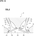
- FIG 2 is an enlarged view of a communicating portion between a combustion chamber 15, an intake port 16, and an exhaust port 17.
- the intake port 16 has a roughly cylindrical opening portion 16a provided in the portion communicating with the combustion chamber 15.
- Formed in an annular edge part of the opening portion 16a is an annular valve seat film 16b that comes into contact with the valve head 18b of the intake valve 18.
- an upper surface of the valve head 18b comes into contact with the valve seat film 16b and closes up the intake port 16.
- the intake valve 18 moves downward along the axial direction of the valve stem 18a, a gap is formed between the upper surface of the valve head 18b and the valve seat film 16b and the intake port 16 is opened.
- the exhaust port 17 is provided with a roughly circular opening 17a in the communicating portion between the intake port 16 and the combustion chamber 15, and formed in an annular edge part of the opening 17a is an annular valve seat film 17b that comes into contact with the valve head 19b of the exhaust valve 19.
- an upper surface of the valve head 19b comes into contact with the valve seat film 17b and closes up the exhaust port 17.
- a gap is formed between the upper surface of the valve head 19b and the valve seat film 17b and the exhaust port 17 is opened.
- a diameter of the opening portion 16a of the intake port 16 is set larger than a diameter of the opening 17a of the exhaust port 17.
- the valve seat films 16b and 17b are formed by cold spraying directly on the annular edge parts of the openings 16a and 17a of the cylinder head 12.
- Cold spraying is a method in which a working gas at a temperature lower than the melting point or softening point of a raw material powder is brought to a supersonic flow, the working gas is charged with raw material powder carried by a carrier gas, the gas with the powder is sprayed from a nozzle tip to collide with a base material while in a solid-phase state, and a coating film is formed by plastic deformation of the raw material powder.
- the characteristics of cold spraying are that a dense coating film that does not oxidize can be obtained in the atmosphere, thermal alteration is minimized because the effect of heat on the material particles is small, the film is formed at a fast rate, the film can be made thicker, and adhesion efficiency is high. Because of the fast film-forming rate and the thick film in particular, cold spraying is suitable when the present invention is applied with structural materials such as the valve seat films 16b and 17b of the internal combustion engine 1.
- FIG 3 is a schematic diagram of a cold spray device 2 of the present embodiment, which is used to form the valve seat films 16b and 17b described above.
- the cold spray device 2 of the present embodiment is provided with a gas supply section 21 that supplies the working gas and the carrier gas, a raw material powder supply section 22 that supplies the raw material powder for the valve seat films 16b and 17b, a spray gun 23 that sprays the raw material powder as a supersonic flow using working gas of which the temperature is not higher than the melting point of the powder, and a refrigerant circulation circuit 27 that cools a nozzle 23d.
- the gas supply section 21 is provided with a compressed gas vessel 21a, a working gas line 21 b, and a carrier gas line 21c.
- the working gas line 21b and the carrier gas line 21c are each provided with a pressure adjuster 21d, a flow rate adjustment valve 21e, a flow rate gauge 21f, and a pressure gauge 21g.
- the pressure adjusters 21d, the flow rate adjustment valves 21e, the flow rate gauges 21f, and the pressure gauges 21g are supplied to adjust the respective pressures and flow rates of the working gas and carrier gas from the compressed gas vessel 21a.
- a tape heater or another heater 21i is installed in the working gas line 21b, and the heater 21i heats the working gas line 21b by being supplied with electric power from an electric power source 21h via electric power supply wires 21j and 21j.
- the working gas is introduced into a chamber 23a of the spray gun 23 after being heated by the heater 21i to a temperature lower than the melting point or softening point of the raw material powder.
- a pressure gauge 23b and a thermometer 23c are installed on the chamber 23a, a pressure value and a temperature value detected via respective signal lines 23g and 23g are outputted to a controller (not shown), and these values are supplied for feedback control of the pressure and temperature.
- the raw material powder supply section 22 is provided with a raw material powder supply device 22a, and a weighing scale 22b and a raw material powder supply line 22c added to the raw material powder supply device 22a.
- the carrier gas from the compressed gas vessel 21a passes through the carrier gas line 21c and is introduced into the raw material powder supply device 22a.
- a predetermined amount of raw material powder weighed by the weighing scale 22b is carried into the chamber 23a via the raw material powder supply line 22c.
- the spray gun 23 sprays the raw material powder P, which has been carried into the chamber 23a by the carrier gas, from the tip of the nozzle 23d at a supersonic flow with the aid of the working gas, and causes the raw material powder P to collide in a solid-phase state or in a solid-liquid coexistent state with a base material 24 to form a coating film 24a.
- the cylinder head 12 is applied as the base material 24, and the valve seat films 16b and 17b are formed by spraying the raw material powder P by cold spraying onto the annular edge parts of the openings 16a and 17a of the cylinder head 12.
- the nozzle 23d is internally provided with a flow channel (not shown) through which water or another refrigerant flows.
- the tip end of the nozzle 23d is provided with a refrigerant introduction part 23e through which the refrigerant is introduced into the flow channel, and a base end of the nozzle 23d is provided with a refrigerant discharge part 23f through which the refrigerant in the flow channel is discharged.
- the refrigerant is introduced into the flow channel of the nozzle 23d through the refrigerant introduction part 23e, the refrigerant flows through the flow channel, and the refrigerant is discharged from the refrigerant discharge part 23f, whereby the nozzle 23d is cooled.
- the refrigerant circulation circuit 27, via which the refrigerant is circulated through the flow channel of the nozzle 23d, is provided with a tank 271 that stores the refrigerant, an introduction pipe 274 connected to the above-described refrigerant introduction part 23e, a pump 272 that is connected to the introduction pipe 274 and that causes the refrigerant to flow between the tank 271 and the nozzle 23d, a cooler 273 that cools the refrigerant, and a discharge pipe 275 connected to the refrigerant discharge part 23f.
- the cooler 273 is composed of, for example, a heat exchanger, etc., and the cooler causes the refrigerant that has cooled the nozzle 23d and risen in temperature to exchange heat with air, water, gas, or another refrigerant, thus cooling the refrigerant.
- Refrigerant stored in the tank 271 is drawn into the refrigerant circulation circuit 27 by the pump 272, and the refrigerant is supplied to the refrigerant introduction part 23e via the cooler 273.
- the refrigerant supplied to the refrigerant introduction part 23e flows through the flow channel in the nozzle 23d from the tip-end side toward the rear-end side, during which time the refrigerant exchanges heat with the nozzle 23d and the nozzle 23d is cooled. Having flowed to the rear-end side of the flow channel, the refrigerant is discharged from the refrigerant discharge part 23f to the discharge pipe 275, and returns to the tank 271.
- the refrigerant is circulated in the refrigerant circulation circuit 27 while being cooled, so that the nozzle 23d is cooled, and therefore, the raw material powder P can be kept from adhering to the spray passage of the nozzle 23d.
- valve seats of the cylinder head 12 require heat resistance and abrasion resistance high enough to withstand striking input from the valves in the combustion chambers 15, as well as thermal conductivity high enough to cool the combustion chambers 15.
- the valve seat films 16b and 17b which are formed from, for example, a powder of a precipitation-hardening copper alloy, make it possible to obtain valve seats that are harder than the cylinder head 12, which is formed from an aluminum alloy for casting, and that have exceptional heat resistance and abrasion resistance.
- valve seat films 16b and 17b are formed directly on the cylinder head 12, it is possible to achieve higher thermal conductivity than in priorart valve seats in which separate seat rings are pressed-fitted and formed in port openings. Furthermore, compared to cases of using separate seat rings, not only is it possible to bring the valve seat films closer to a water jacket for cooling, but it is also possible to achieve secondary effects such as increasing throat diameters of the intake ports 16 and the exhaust ports 17 and promoting tumble flow by optimizing port shape.
- the raw material powder P used to form the valve seat films 16b and 17b is preferably a metal that is harder than aluminum alloys for casting and that yields the heat resistance, abrasion resistance, and thermal conductivity needed for the valve seats; for example, it is preferable to use the precipitation-hardening copper alloy mentioned above.
- a Corson alloy containing nickel and silicon, chromium copper containing chromium, zirconium copper containing zirconium, etc., can be used as the precipitation-hardening copper alloy.
- a precipitation-hardening copper alloy containing nickel, silicon, and chromium containing nickel, silicon, and chromium
- a precipitation-hardening copper alloy containing nickel, silicon, and zirconium containing nickel, silicon, chromium, and zirconium
- a precipitation-hardening copper alloy containing chromium and zirconium can be applied.
- a first raw material powder and a second raw material powder can be mixed to form the valve seat films 16b and 17b.
- the first raw material powder it is preferable to use a metal that is harder than aluminum alloys for casting and that yields the heat resistance, abrasion resistance, and thermal conductivity needed for the valve seats; for example, it is preferable to use a precipitation-hardening copper alloy mentioned above.
- a metal harder than the first raw material powder is preferably used as the second raw material powder.
- an iron-based alloy, a cobalt-based alloy, a chromium-based alloy, a nickel-based alloy, a molybdenum-based alloy, or another alloy, or a ceramic, etc. can be applied as the second raw material powder.
- one of these metals can be used alone, or a combination of two or more can be used as appropriate.
- Valve seat films formed by mixing a first raw material powder and a second raw material powder harder than the first raw material powder can have better heat resistance and abrasion resistance than valve seat films formed from only a precipitation-hardening copper alloy.
- Such effects are achieved presumably because the second raw material powder causes an oxide coating film present on the surface of the cylinder head 12 to be removed and a new interface to be formed by exposure, and adhesiveness between the cylinder head 12 and the metal coating film improves.
- Such effects are also presumably because adhesiveness between the cylinder head 12 and the metal coating film are improved by an anchor effect brought about by the second raw material powder being embedded in the cylinder head 12.
- the cylinder head 12 in which the valve seat films 16b and 17b are formed is secured to a pedestal 45, and the tip end of the nozzle 23d of the spray gun 23 is rotated along the annular edge parts of the openings 16a and 17a of the cylinder head 12, whereby raw material powder is sprayed.
- the cylinder head 12 is not caused to rotate and therefore does not need to occupy a large space, and the spray gun 23 has a smaller moment of inertia than the cylinder head 12 and therefore has exceptional rotational transient characteristics and responsiveness.
- a high-pressure pipe (high-pressure hose) constituting the working gas line 21b is connected to the spray gun 23 as shown in Fig.
- Figure 4 is a front view of the spray gun 23 of one embodiment of the cold spray device 2 according to the present invention
- Fig. 5 is a cross-sectional view along line VI-VI in Fig. 4
- Fig. 6 is a front view of a state in which the spray gun 23 in Fig. 4 is offset
- Fig. 7 is a front view of a film formation factory including the cold spray device 2 according to the present invention
- Fig. 8 is a plan view of Fig. 7 .
- the cylinder head 12 which is a workpiece, is placed in a predetermined orientation on the pedestal 45 of a film formation booth 42 of a film formation factory 4 shown in Figs. 7 and 8 .
- the cylinder head 12 is secured to the pedestal 45 so that the recesses 12b of the cylinder head 12 are at the upper surface, and the pedestal 45 is tilted so that center lines of the openings 16a of the intake ports 16 or center lines of the openings 17a of the exhaust ports 17 are oriented in a vertical direction.
- the film formation factory 4 is provided with the film formation booth 42, in which a film formation process is carried out, and a carrier booth 41.
- a pedestal 45 on which the cylinder head 12 is placed and an industrial robot 25 that holds the spray gun 23 are installed in the film formation booth 42.
- the carrier booth 41 is provided at the front portion of the film formation booth 42, cylinder heads 12 are carried in and out between the exterior and the carrier booth 41 through a door 43, and cylinder heads 12 are carried in and out between the carrier booth 41 and the film formation booth 42 through a door 44.
- a cylinder head 12 that has ended the preceding process is carried out to the exterior from the carrier booth 41.
- the carrier booth 41 is installed and the film formation process is performed with the door 44 closed, whereby other operations can be performed simultaneously with the film formation process, such as carrying out a processed cylinder head 12 and carrying in a to-be-processed cylinder head 12.
- the spray gun 23 is rotatably mounted on a base plate 26 secured to a hand 251 of the industrial robot 25 installed in the film formation booth 42 of the film formation factory 4 shown in Figs. 7 and 8 .
- a configuration of the spray gun 23 of the present embodiment is described below with reference to Figs. 4 to 6 .
- a bracket 252 is secured to the hand 251 of the industrial robot 25, the base plate 26 is rotatably attached to the bracket 252, and the spray gun 23 is secured to the base plate 26.
- the bracket 252 is secured to the hand 251 of the industrial robot 25
- a body of a motor 29 is secured to the bracket 252
- a drive shaft 291 of the motor 29 is connected to a first base plate 261 via a pulley and a belt (not shown), and the first base plate 261 is caused to rotate relative to the bracket.
- the motor 29 rotates in two directions over a range of, for example, 360° at maximum. For example, if the drive shaft 291 is caused to rotate 360° clockwise in relation to the opening portion 16a of one intake port 16, the drive shaft 291 is caused to rotate 360° counterclockwise in relation to the opening portion 16a of the next intake port 16, and thereafter the same action is repeated.
- the base plate 26 is composed of the first base plate 261 and a second base plate 262, and the first base plate 261 and the second base plate 262 are provided so as to be capable of sliding in a direction (the left-right direction in Fig. 4 ) orthogonal to a rotational axis C via a linear guide 281. An amount by which the second base plate 262 is offset relative to the first base plate 261 is adjusted and a spray diameter D of a film-forming material is set by driving a hydraulic cylinder 282.
- a cover 263 is mounted on the second base plate 262 and the spray gun 23 is secured to a lower end part of the cover.
- the spray gun 23 is secured to the second base plate 262 via the cover 263 so that the spraying direction of the nozzle 23d is directed toward the rotational axis C. Because the second base plate 262 can be offset in relation to the first base plate 261 by the linear guide 281 and the hydraulic cylinder 282 mentioned above, the position of the tip end of the nozzle 23d of the spray gun 23 can be adjusted to be horizontal in relation to the rotational axis C.
- the spray diameter D will be smaller should the gun distance be the same. Because the openings 16a of the intake ports 16 are larger in diameter than the openings 17a of the exhaust ports 17, the tip end is in the position on the rotational axis C shown in Fig. 4 when the valve seat films 16b are formed in the openings 16a of the intake ports 16, and the tip end is in the position separated from the rotational axis C shown in Fig. 6 when the valve seat films 17b are formed in the openings 17a of the exhaust ports 17.
- the working gas line 21b shown in Fig. 3 which guides high-pressure gas at 3-10 MPa supplied from the compressed gas vessel 21a to the spray gun 23, forms one pipe bundle 20 with other pipes described hereinafter, and hangs down to reach the spray gun 23 from an upper part of the base plate 26 mounted to the hand 251 of the industrial robot 25 as shown in Fig. 7 .
- the working gas line is separably connected via a swivel joint or another rotating coupling 21k, and the heater 21i is provided below the coupling, as shown in Fig. 4 .
- the working gas line 21b can be shaped into, for example, a helix in advance so as to encircle the rotational axis C, but a high-pressure hose that can withstand high pressures of 3-10 MPa is hard and retains shape; therefore, a shape-retaining mold can be provided on the outer periphery so that the high-pressure hose conforms to the helical shape.
- the raw material powder supply line 22c which is shown in Fig. 3 and which guides the raw material powder supplied from the raw material powder supply device 22a to the spray gun 23, is arranged in the periphery of the industrial robot 25 as the pipe bundle 20 shown in Fig. 7 , is hung down to the spray gun 23 from the upper part of the base plate 26. Below the base plate 26 in this configuration, the raw material powder supply line 22c is configured in the pipe arrangement including metal pipes and metal couplings and is connected to the chamber 23a of the spray gun 23 as shown in Fig. 4 .
- the electric power supply wires 21j and 21j which are shown in Fig. 3 and which guide electric power supplied from the electric power source 21h to the heater 21i, are arranged in the periphery of the industrial robot 25 as the pipe bundle 20 shown in Fig. 7 , hung down from the upper part of the base plate 26, and connected to the heater 21i. Additionally, a signal wire 23g that outputs a detection signal from the pressure gauge 23b to a controller (not shown) and a signal wire 23h that outputs a detection signal from the thermometer 23c to a controller (not shown), these signal wires being shown in Fig.
- the introduction pipe 274 and the discharge pipe 275 which are shown in Fig. 3 and which guide the refrigerant supplied from the refrigerant circulation circuit 27 to the nozzle 23d of the spray gun 23, are arranged in the periphery of the industrial robot 25 as the pipe bundle 20 shown in Fig. 7 , hung from the upper part of the base plate 26, and connected to the refrigerant introduction part 23e at the tip end of the nozzle 23d and the refrigerant discharge part 23f at the base end of the nozzle 23d.
- the introduction pipe 274 and the discharge pipe 275 are configured in the piping including the metal pipes and metal couplings and are connected to the nozzle 23d of the spray gun 23, as shown in Fig. 4 .
- the working gas line 21b which is configured from a high-pressure hose that is hard and very stiff against deformation, is arranged such that the rotating coupling 21k thereof is disposed on the line of the rotational axis C as shown in Fig. 4 , and below the rotating coupling 21k, the working gas line extends along and encircles the rotational axis C.
- the electric power supply wires 21j and 21j, the raw material powder supply line 22c, the introduction pipe 274, the discharge pipe 275, and the signal wires 23g, 23h are disposed around the rotational axis C in positions encircling the working gas line 21b, as shown in Fig. 5 .
- Figure 9 is a flowchart of steps for processing the valve portion in the method for manufacturing the cylinder head 12 of the present embodiment.
- the method for manufacturing the cylinder head 12 of the present embodiment includes a casting step S1, a cutting step S2, a coating step S3, and a finishing step S4, as shown in Fig. 9 .
- the steps for processing portions other than the valve are omitted for the sake of simplifying the description.
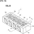
- FIG. 10 is a perspective view of a cylinder head rough material 3 shaped by casting in the casting step S1, as seen from a side of an attachment surface 12a for the cylinder block 11.
- the cylinder head rough material 3 is provided with four recesses 12b, and the recesses 12b each have two intake ports 16 and two exhaust ports 17.
- the two intake ports 16 and the two exhaust ports 17 of an individual recess 12b merge together in the cylinder head rough material 3, and all communicate with openings provided in both side surfaces of the cylinder head rough material 3.
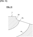
- Figure 11 is a cross-sectional view of the cylinder head rough material 3 along line XI-XI of Fig. 10 , showing an intake port 16.
- the intake port 16 is provided with a circular opening portion 16a exposed in a recess 12b of the cylinder head rough material 3.
- the cylinder head rough material 3 is subjected to milling by an end mill, a ball end mill, etc., and an annular valve seat portion 16c is formed in the opening portion 16a of the intake port 16 as shown in Fig. 12 .
- the annular valve seat portion 16c is an annular groove constituting a base shape of a valve seat film 16b, and is formed in an outer periphery of the opening portion 16a.
- the raw material powder P is sprayed by cold spraying to form a coating film on the annular valve seat portion 16c, and the valve seat film 16b is formed on the coating film as a foundation. Therefore, the annular valve seat portion 16c is formed to be one size larger than the valve seat film 16b.
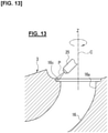
- the raw material powder P is sprayed onto the annular valve seat portion 16c of the cylinder head rough material 3 using the cold spray device 2 of the present embodiment, and the valve seat film 16b is formed. More specifically, in the coating step S3, the cylinder head rough material 3 is secured in place and the spray gun 23 is rotated at a constant speed so that the raw material powder P is blown onto the entire periphery of the annular valve seat portion 16c while the annular valve seat portion 16c and the nozzle 23d of the spray gun 23 are kept at a constant distance in the same orientation, as shown in Fig. 13 .
- the tip end of the nozzle 23d of the spray gun 23 is held in the hand 251 of the industrial robot 25, above the cylinder head 12 secured to the pedestal 45.
- the pedestal 45 or the industrial robot 25 sets the position of the cylinder head 12 or the spray gun 23 so that a center axis Z of the intake port 16 in which the valve seat film 16b is formed is vertical and is the same as the rotational axis C, as shown in Fig. 4 .
- a coating film is formed on the entire periphery of the annular valve seat portion 16c due to the spray gun 23 being rotated about the C axis by the motor 29 while the raw material powder P is blown onto the annular valve seat portion 16c from the nozzle 23d.
- the nozzle 23d introduces the refrigerant supplied from the refrigerant circulation circuit 27 into the flow channel from the refrigerant introduction part 23e.
- the refrigerant cools the nozzle 23d while flowing from the tip-end side toward the rear-end side of the flow channel formed inside the nozzle 23d. Having flowed to the rear-end side of the flow channel, the refrigerant is discharged from the flow channel by the refrigerant discharge part 23f and recovered.
- the rotation of the spray gun 23 is temporarily stopped.
- the industrial robot 25 moves the spray gun 23 so that the center axis Z of the intake port 16 in which the valve seat film 16b will next be formed coincides with a reference axis of the industrial robot 25.
- the motor 29 restarts the rotation of the spray gun 23 and a valve seat film 16b is formed on the next intake port 16.
- the valve seat films 16b and 17b are hereinafter formed on all of the intake ports 16 and exhaust ports 17 of the cylinder head rough material 3 by repeating this operation.
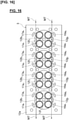
- Figure 16 is a plan view of the cylinder head rough material 3, depicting an example of movement trajectories MT when the nozzle 23d of the cold spray device 2 moves over the openings of the intake ports 16 and the exhaust ports 17 in the film forming method according to the present invention.
- the nozzle 23d is moved along the movement trajectories MT shown by the arrows, relative to the openings 16a of the eight intake ports 16 and the openings 17a of the eight exhaust ports 17 of the cylinder head rough material 3 shown in Fig. 16 .
- the following is a description of the movement trajectory MT relative to the intake ports 16, but the movement trajectory relative to the exhaust ports 17 is set in the same manner.
- the nozzle 23d rotates 360° clockwise in relation to one intake port 16, the nozzle then rotates 360° counterclockwise in relation to the next intake port 16.
- the nozzle 23d then moves in relation to the eight intake ports 16 while repeatedly rotating clockwise and counterclockwise. Specifically, the nozzle 23d, rotates counterclockwise in relation to openings 16as, 16a 6 , 16a 4 , and 16a 2 of four intake ports shown in Fig. 16 , and rotates clockwise in relation to openings 16a 7 , 16as, 16a 3 , 16a 1 of the remaining intake ports.
- the movement trajectory MT relative to the eight intake ports 16 is configured from a circular trajectory T for each of the annular valve seat portions 16c of the intake ports 16 and a connecting trajectory CT by which adjacent ones the circular trajectories T are connected, and the movement trajectory MT is thus a series of continuous trajectories.
- the nozzle 23d is thus moved along the movement trajectory MT while raw material powder is continuously sprayed without interruption from the nozzle 23d.
- the circular trajectory for one of the annular valve seat portion 16c begins from a film formation starting point, moves clockwise or counterclockwise, and then overlaps at the film formation starting point, this overlapping portion being a film formation finishing point.
- Figure 20 is an enlarged plan view of a movement trajectory MT according to a comparative example, for the opening portion 16as of one of the intake ports 16 positioned in the lower right of Fig. 16 .
- the nozzle 23d is caused to rotate counterclockwise in relation to the annular valve seat portion 16c of the opening portion 16as of this intake port 16; therefore, the movement trajectory MT according to the comparative example shown in Fig. 20 causes the nozzle 23d to move to the annular valve seat portion 16c from the right end toward the left in Fig.
- the nozzle 23d is caused to rotate counterclockwise in the circular trajectory, after which the orientation is changed at the film formation finishing point which overlaps the film formation starting point, and the nozzle 23d is moved to the left in Fig. 20 .
- the movement trajectory MT according to such a comparative example, there is a turnback point TP 1 at which the movement speed of the nozzle 23d reaches zero at the film formation starting point of the annular valve seat portion 16c, and there is a turnback point TP 2 at which the movement speed of the nozzle 23d reaches zero at the film formation finishing point.
- turnback points TP 1 , TP 2 refer to points on the movement trajectory MT at which the movement speed of the nozzle 23d reaches zero or decreases to a value close to zero, and also refer to points at which the movement trajectory changes to a right angle or an acute angle ( ⁇ 90°).
- Figure 21 is a cross-section of a coating film in an overlapping portion when a film has been formed along the movement trajectory MT of the comparative example of Fig. 20 .
- the speed of the nozzle 23d temporarily reaches zero but the raw material powder continues to be sprayed; therefore, the valve seat film 16bi constituting the first layer will have a steep end part slant S as shown in Fig. 21 .
- the circular trajectory of the annular valve seat portion 16c which is the part where a film is formed, includes a turnback point in the first layer within the range from the film formation starting point to the film formation finishing point (including the end point), the end part slant S will be steep at the turnback point.
- the problem of inadequate flattening does not occur as long as the end part slant S of the valve seat film 16b 2 of the first layer is not steep.
- the turnback point TP 1 is set to be not on the circular trajectory T but on the connecting trajectory CT so that the turnback point TP 1 is not included in the first layer of the circular trajectory T.
- Figure 17 is a plan view of the movement trajectory MT relative to the opening portion 16as of the one intake port 16 of Fig. 16 .
- the movement trajectory MT according to the present example shown in Fig. 17 causes the nozzle 23d to move in a straight line toward the left from the right end of the drawing to the surface 12a where the cylinder head rough material 3 attaches to the cylinder block 11, below and to the left of the annular valve seat portion 16c.
- the nozzle 23d changes direction at the turnback point TP 1 and is moved diagonally right and upward toward the annular valve seat portion 16c, after which the nozzle 23d is caused to rotate counterclockwise in the circular trajectory T with this point as the film formation starting point, the nozzle changes direction with the film formation finishing point, which overlaps the film formation starting point, as the turnback point TP 2 of the second layer, and the nozzle 23d is moved to the left in Fig. 20 .
- Figure 18 is a cross-section of a coating film on an overlapping portion when a film has been formed in the movement trajectory MT of Fig. 17 .
- the surface of the valve seat film 16b 1 of the first layer is formed flat because at the film formation starting point of the valve seat film 16b 1 of the first layer, the movement speed of the nozzle 23d is a speed that is not zero.
- the collision direction is substantially perpendicular to the surface of the valve seat film 16b 1 of the first layer; therefore, the raw material powder of the second layer is adequately flattened and the internal pore diameter of the valve seat film 16b 2 is adequately small.
- the turnback point TP 1 that can be the first layer of the overlapping portion, i.e., the turnback point set upstream of the film formation starting point of the annular valve seat portion 16c is set on the connecting trajectory CT, but the turnback point TP 2 that becomes the second layer of the overlapping portion is set on the circular trajectory T because the end part slant S at this turnback point can be steep.
- the distance between the nozzle 23d and the attachment surface 12a of the cylinder head rough material 3, i.e., the gun distance may be increased at the turnback point TP 1 set on the connecting trajectory CT.
- the gun distance is gradually increased as the nozzle approaches turnback point TP 1 , after which the gun distance can gradually return to the original distance as the nozzle moves away from the turnback point TP 1 .
- Figure 19 is a plan view of another example of a movement trajectory MT for an opening portion 16as of one intake port 16.
- the turnback point TP 2 of the second layer is set on the circular trajectory T for the annular valve seat portion 16c, but can be set on the attachment surface 12a of the cylinder head rough material 3 as shown in Fig. 19 , as with the turnback point TP 1 of the first layer.
- finishing is performed on the valve seat films 16b and 17b, and on the intake ports 16 and the exhaust ports 17.
- the surfaces of the valve seat films 16b and 17b are milled using a ball end mill, and the valve seat films 16b are adjusted to a predetermined shape.
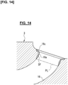
- a ball end mill is inserted into the intake ports 16 from the openings 16a, and the inner peripheral surfaces of the intake ports 16 at the sides having the openings 16a are each cut along a processing line PL shown in Fig. 14 .
- the processing line PL is a range in which a surplus coating film SF, which results from the raw material powder P scattering and adhering to the inside of the intake port 16, is formed comparatively thick; i.e., a range in which the surplus coating film SF is formed thick enough to affect the intake performance of the intake port 16.
- FIG. 15 shows an intake port 16 after the finishing step S4.
- a valve seat film 17b is formed in the exhaust port 17 via formation of a small-diameter part in the exhaust port 17 by cast-shaping, formation of an annular valve seat part by cutting, cold spraying on the annular valve seat part, and finishing. Therefore, a detailed description shall not be given for the procedure of forming the valve seat films 17b in the exhaust ports 17.
- the cylinder head rough material 3 having the plurality of annular valve seat portions 16c, which are not continuous with each other, and the nozzle 23d of the cold spray device 2 are moved relative to each other along the continuous movement trajectory MT configured from the circular trajectories T for the annular valve seat portions 16c and the connecting trajectories CT that link the plurality of circular trajectories T, while the raw material powder is continuously sprayed from the nozzle 23d, and the raw material powder is sprayed by cold spraying to form the valve seat films 16b on each of the plurality of annular valve seat portions 16c, wherein the turnback points TP 1 , at which the relative speed between the cylinder head rough material 3 and the nozzle 23d decreases in the movement trajectory MT, are set not on the circular trajectories T but on the connecting trajectories CT.
- valve seat films 16b 2 of the second layers which are the film formation finishing points, overlap the valve seat films 16bi, the collision direction is substantially perpendicular to the surfaces of the valve seat films 16b 1 of the first layers; therefore, the raw material powder of the second layers is adequately flattened and the internal pore diameters of the valve seat films 16b 2 are adequately small.
- the parts where a film is formed are the entire peripheries of the openings 16a and 17a of the intake ports 16 or the exhaust ports 17 of the cylinder head 12, and the turnback points TP 1 are set in the surface 12a of the cylinder head rough material 3 that attaches to the cylinder block 11.
- the surplus coating film formed along the connecting trajectories CT in the surface 12a of the cylinder head rough material 3 that attaches to the cylinder block 11 can thereby be easily removed along with other portions in the finishing step S4, which is a later step.
- the thickness of the surplus coating film formed on the attachment surface 12a decreases and the depth by which the surplus coating film is removed in the finishing step S4 can be reduced.
- the turnback points TP 2 which are set at the film formation finishing points of the annular valve seat portions 16c, are set on the circular trajectories T for the annular valve seat portions 16c.
- Turnback points set upstream from the film formation starting points of the annular valve seat portions 16c are set on the connecting trajectories CT, but the turnback points TP 2 that become the second layers of the overlapping portions may have a steep end part slant S, and can therefore be set on the circular trajectories T.
- annular valve seat portions 16c described above are equivalent to the parts where a film is formed according to the present invention.
Landscapes
- Engineering & Computer Science (AREA)
- Chemical & Material Sciences (AREA)
- Mechanical Engineering (AREA)
- Chemical Kinetics & Catalysis (AREA)
- Materials Engineering (AREA)
- Metallurgy (AREA)
- Organic Chemistry (AREA)
- General Engineering & Computer Science (AREA)
- Combustion & Propulsion (AREA)
- Other Surface Treatments For Metallic Materials (AREA)
- Cylinder Crankcases Of Internal Combustion Engines (AREA)
- Application Of Or Painting With Fluid Materials (AREA)
Abstract
Description
- The present invention relates to a method of forming a film by cold spraying.
- There is a known method for manufacturing a sliding member in which a valve seat having exceptional abrasion resistance at high temperature can be formed by blowing a powder of metal or another raw material by cold spraying onto a seating portion of an engine valve (Patent Document 1).
- Patent Document 1:
WO 2017/022505 A1 - When enabled for multi-valve capability, automobile engines are provided with a plurality of intake and exhaust valves. Therefore, when valve seats are formed by cold spraying in the seating portions of a plurality of valves, it is necessary for a cylinder head and a nozzle of a cold spray device to be moved relative to each other, the nozzle and the plurality of seating portions to be faced sequentially toward each other, and a raw material powder to be ejected from the nozzle and blown onto the seating portions faced toward the nozzle.
- When the spraying of raw material powder is interrupted, the cold spray device requires a standby time of several minutes until the raw material powder will again be stably blown. Therefore, it is preferable that raw material powder be continuously sprayed for as long as possible without interruption. However, when one valve seat film is formed, the nozzle and the cylinder head are moved relative to each other in a 360° circle, but mishaps can occur, such as an overlapping portion being created at the film forming starting point and film formation finishing point of the circular trajectory, or a turnback point appearing where the nozzle movement speed reaches zero in order to form the next valve seat film from the film formation finishing point.
- In a trajectory where a turnback point arises in the first layer of an overlapping portion, the inclination angle of the surface of the starting point in the first layer becomes steep, and when a second layer is sprayed at this location, the flattening of the raw material powder is hindered and an insufficient coating film is formed.
- A problem to be solved by the present invention is to provide a coldspraying film forming method with which the formation of an insufficient coating film can be prevented.
- The present invention overcomes the problem described above by providing a film forming method in which a raw material powder is continuously sprayed to form a coating film along a continuous movement trajectory configured from non-mutually-continuous trajectories for a plurality of parts where a film is formed, and a connecting trajectory that links the trajectories for the plurality of parts where a film is formed, wherein a turnback point where a relative speed of a workpiece and a nozzle decreases in the movement trajectories is set on the connecting trajectory.
- According to the present invention, a turnback point where the relative speed of a workpiece and a nozzle is low in a movement trajectory is set on a connection trajectory, and the turnback point will therefore not be in a coating film in a first layer of an overlapping portion. As a result, the forming of an insufficient coating film can be minimized.
-
-
Figure 1 is a cross-sectional view of a cylinder head on which a valve seat film is formed using a cold spray device according to the present invention; -
Figure 2 is an enlarged cross-sectional view of a periphery of the valve ofFig. 2 ; -
Figure 3 is a configuration diagram of one embodiment of the cold spray device according to the present invention; -
Figure 4 is a front view of a spray gun of one embodiment of the cold spray device according to the present invention; -
Figure 5 is a cross-sectional view along line V-V inFig. 4 ; -
Figure 6 is a front view of a state in which the spray gun inFig. 4 has been offset; -
Figure 7 is a front view of a film formation factory including the cold spray device according to present invention; -
Figure 8 is a plan view ofFig. 7 ; -
Figure 9 is a flowchart of a procedure for manufacturing a cylinder head using the cold spray device according to the present invention. -
Figure 10 is a perspective view of a cylinder head rough material on which a valve seat film is formed using the cold spray device according to the present invention. -
Figure 11 is a cross-sectional view of an intake port along line XI-XI ofFig. 10 . -
Figure 12 is a cross-sectional view of a state in which an annular valve seat part has been formed by a cutting step in the intake port ofFig. 11 . -
Figure 13 is a cross-sectional view of a state in which a valve seat film is formed in the intake port ofFig. 12 . -
Figure 14 is a cross-sectional view of an intake port in which a valve seat film has been formed. -
Figure 15 is a cross-sectional view of an intake port after the finishing step ofFig. 9 . -
Figure 16 is a plan view of a cylinder head rough material, depicting an example of movement trajectories when a nozzle of the cold spray device moves over openings of intake ports and exhaust ports in the film forming method according to the present invention. -
Figure 17 is a plan view of a movement trajectory relative to one intake port ofFig. 16 . -
Figure 18 is a cross-section of a coating film when a film has been formed along the movement trajectory ofFig. 17 . -
Figure 19 is a plan view of another example of a movement trajectory relative to one intake port. -
Figure 20 is a drawing of a movement trajectory of a comparative example in which a film is formed with turnback points set at an overlapping portion of a film formation starting point and a film formation finishing point. -
Figure 21 is a cross-section of a coating film when a film has been formed along the movement trajectory ofFig. 20 . - An embodiment of the present invention is described below on the basis of the drawings. There shall first be described an
internal combustion engine 1 provided with a valve seat film, in which a cold spray device of the embodiment is preferably applied.Figure 1 is a cross-sectional view of theinternal combustion engine 1, showing mainly the configuration around the cylinder head. - The
internal combustion engine 1 comprises acylinder block 11 and acylinder head 12 assembled on an upper part of thecylinder block 11. Theinternal combustion engine 1 is, for example, an in-line four-cylinder gasoline engine, and thecylinder block 11 has fourcylinders 11a arranged in the depth direction of the drawing. Thecylinders 11a accommodatepistons 13 that move in a reciprocating manner vertically in the drawing, and thepistons 13 link via connectingrods 13a tocrankshafts 14 extending in the depth direction of the drawing. - In a
surface 12a of thecylinder head 12 that attaches to thecylinder block 11, in positions corresponding to thecylinders 11a, fourrecesses 12b constitutingcombustion chambers 15 of the cylinders are formed. Thecombustion chambers 15 are spaces for combusting an air-fuel mixture of fuel and intake air, and are configured from therecesses 12b of thecylinder head 12,top surfaces 13b of thepistons 13, and inner peripheral surfaces of thecylinders 11a. - The
cylinder head 12 is provided withintake ports 16 via which thecombustion chambers 15 and oneside surface 12c of thecylinder head 12 communicate. Theintake ports 16 assume a substantially cylindrical form that is curved, and guide intake air into thecombustion chambers 15 from an intake manifold (not shown) connected to theside surface 12c. Thecylinder head 12 is also provided withexhaust ports 17 that communicate thecombustion chambers 15 and anotherside surface 12d of thecylinder head 12. Theexhaust ports 17 have roughly cylindrical shapes curved in the same manner as theintake ports 16, and discharge exhaust air produced in thecombustion chambers 15 to an exhaust manifold (not shown) connected to theside surface 12d. Theinternal combustion engine 1 of the present embodiment has twointake ports 16 andexhaust ports 17 each for onecylinder 11a. - The
cylinder head 12 is provided withintake valves 18 that open and close theintake ports 16 in relation to thecombustion chambers 15, andexhaust valves 19 that open and close theexhaust ports 17 in relation to thecombustion chambers 15. Theintake valves 18 and theexhaust valves 19 are each provided with avalve stem valve head valve stem cylindrical valve guides cylinder head 12. Theintake valves 18 and theexhaust valves 19 are thereby free to move along axial directions of thevalve stems combustion chambers 15. -
Figure 2 is an enlarged view of a communicating portion between acombustion chamber 15, anintake port 16, and anexhaust port 17. Theintake port 16 has a roughlycylindrical opening portion 16a provided in the portion communicating with thecombustion chamber 15. Formed in an annular edge part of theopening portion 16a is an annularvalve seat film 16b that comes into contact with thevalve head 18b of theintake valve 18. When theintake valve 18 moves upward along the axial direction of thevalve stem 18a, an upper surface of thevalve head 18b comes into contact with thevalve seat film 16b and closes up theintake port 16. Conversely, when theintake valve 18 moves downward along the axial direction of thevalve stem 18a, a gap is formed between the upper surface of thevalve head 18b and thevalve seat film 16b and theintake port 16 is opened. - The
exhaust port 17 is provided with a roughlycircular opening 17a in the communicating portion between theintake port 16 and thecombustion chamber 15, and formed in an annular edge part of the opening 17a is an annularvalve seat film 17b that comes into contact with thevalve head 19b of theexhaust valve 19. When theexhaust valve 19 moves upward along the axial direction of thevalve stem 19a, an upper surface of thevalve head 19b comes into contact with thevalve seat film 17b and closes up theexhaust port 17. Conversely, when theexhaust valve 19 moves downward along the axial direction of thevalve stem 19a, a gap is formed between the upper surface of thevalve head 19b and thevalve seat film 17b and theexhaust port 17 is opened. A diameter of theopening portion 16a of theintake port 16 is set larger than a diameter of theopening 17a of theexhaust port 17. - In the four-cycle
internal combustion engine 1, only theintake valve 18 is opened when thepiston 13 descends, whereby the air-fuel mixture is introduced into thecylinder 11a from the intake port 16 (intake stroke). Theintake valve 18 and theexhaust valve 19 are then closed, and thepiston 13 is raised to roughly top dead center to compress the air-fuel mixture inside thecylinder 11a (compression stroke). When thepiston 13 has reaches roughly top dead center, the compressed air-fuel mixture is ignited by a sparkplug and the air-fuel mixture thereby explodes. This explosion causes thepiston 13 to descend to bottom dead center, and the explosion is converted to rotational force via a linked crankshaft 14 (combustion/expansion stroke). Lastly, when thepiston 13 reaches bottom dead center and begins to ascend again, only theexhaust valve 19 is opened and exhaust inside thecylinder 11a is discharged to the exhaust port 17 (exhaust stroke). Theinternal combustion engine 1 generates output by repeating the cycle described above. - The
valve seat films openings cylinder head 12. Cold spraying is a method in which a working gas at a temperature lower than the melting point or softening point of a raw material powder is brought to a supersonic flow, the working gas is charged with raw material powder carried by a carrier gas, the gas with the powder is sprayed from a nozzle tip to collide with a base material while in a solid-phase state, and a coating film is formed by plastic deformation of the raw material powder. In comparison to thermal spraying, in which a material is melted and deposited on a base material, the characteristics of cold spraying are that a dense coating film that does not oxidize can be obtained in the atmosphere, thermal alteration is minimized because the effect of heat on the material particles is small, the film is formed at a fast rate, the film can be made thicker, and adhesion efficiency is high. Because of the fast film-forming rate and the thick film in particular, cold spraying is suitable when the present invention is applied with structural materials such as thevalve seat films internal combustion engine 1. -
Figure 3 is a schematic diagram of acold spray device 2 of the present embodiment, which is used to form thevalve seat films cold spray device 2 of the present embodiment is provided with agas supply section 21 that supplies the working gas and the carrier gas, a raw materialpowder supply section 22 that supplies the raw material powder for thevalve seat films spray gun 23 that sprays the raw material powder as a supersonic flow using working gas of which the temperature is not higher than the melting point of the powder, and arefrigerant circulation circuit 27 that cools anozzle 23d. - The
gas supply section 21 is provided with acompressed gas vessel 21a, a workinggas line 21 b, and acarrier gas line 21c. The workinggas line 21b and thecarrier gas line 21c are each provided with apressure adjuster 21d, a flowrate adjustment valve 21e, aflow rate gauge 21f, and apressure gauge 21g. Thepressure adjusters 21d, the flowrate adjustment valves 21e, theflow rate gauges 21f, and thepressure gauges 21g are supplied to adjust the respective pressures and flow rates of the working gas and carrier gas from the compressedgas vessel 21a. - A tape heater or another
heater 21i is installed in the workinggas line 21b, and theheater 21i heats the workinggas line 21b by being supplied with electric power from anelectric power source 21h via electricpower supply wires chamber 23a of thespray gun 23 after being heated by theheater 21i to a temperature lower than the melting point or softening point of the raw material powder. Apressure gauge 23b and athermometer 23c are installed on thechamber 23a, a pressure value and a temperature value detected viarespective signal lines - The raw material
powder supply section 22 is provided with a raw materialpowder supply device 22a, and a weighingscale 22b and a raw materialpowder supply line 22c added to the raw materialpowder supply device 22a. The carrier gas from the compressedgas vessel 21a passes through thecarrier gas line 21c and is introduced into the raw materialpowder supply device 22a. A predetermined amount of raw material powder weighed by the weighingscale 22b is carried into thechamber 23a via the raw materialpowder supply line 22c. - The
spray gun 23 sprays the raw material powder P, which has been carried into thechamber 23a by the carrier gas, from the tip of thenozzle 23d at a supersonic flow with the aid of the working gas, and causes the raw material powder P to collide in a solid-phase state or in a solid-liquid coexistent state with abase material 24 to form acoating film 24a. In the present embodiment, thecylinder head 12 is applied as thebase material 24, and thevalve seat films openings cylinder head 12. - The
nozzle 23d is internally provided with a flow channel (not shown) through which water or another refrigerant flows. The tip end of thenozzle 23d is provided with arefrigerant introduction part 23e through which the refrigerant is introduced into the flow channel, and a base end of thenozzle 23d is provided with arefrigerant discharge part 23f through which the refrigerant in the flow channel is discharged. The refrigerant is introduced into the flow channel of thenozzle 23d through therefrigerant introduction part 23e, the refrigerant flows through the flow channel, and the refrigerant is discharged from therefrigerant discharge part 23f, whereby thenozzle 23d is cooled. - The
refrigerant circulation circuit 27, via which the refrigerant is circulated through the flow channel of thenozzle 23d, is provided with atank 271 that stores the refrigerant, anintroduction pipe 274 connected to the above-describedrefrigerant introduction part 23e, apump 272 that is connected to theintroduction pipe 274 and that causes the refrigerant to flow between thetank 271 and thenozzle 23d, a cooler 273 that cools the refrigerant, and adischarge pipe 275 connected to therefrigerant discharge part 23f. The cooler 273 is composed of, for example, a heat exchanger, etc., and the cooler causes the refrigerant that has cooled thenozzle 23d and risen in temperature to exchange heat with air, water, gas, or another refrigerant, thus cooling the refrigerant. - Refrigerant stored in the
tank 271 is drawn into therefrigerant circulation circuit 27 by thepump 272, and the refrigerant is supplied to therefrigerant introduction part 23e via thecooler 273. The refrigerant supplied to therefrigerant introduction part 23e flows through the flow channel in thenozzle 23d from the tip-end side toward the rear-end side, during which time the refrigerant exchanges heat with thenozzle 23d and thenozzle 23d is cooled. Having flowed to the rear-end side of the flow channel, the refrigerant is discharged from therefrigerant discharge part 23f to thedischarge pipe 275, and returns to thetank 271. Thus, the refrigerant is circulated in therefrigerant circulation circuit 27 while being cooled, so that thenozzle 23d is cooled, and therefore, the raw material powder P can be kept from adhering to the spray passage of thenozzle 23d. - The valve seats of the
cylinder head 12 require heat resistance and abrasion resistance high enough to withstand striking input from the valves in thecombustion chambers 15, as well as thermal conductivity high enough to cool thecombustion chambers 15. To comply with these requirements, thevalve seat films cylinder head 12, which is formed from an aluminum alloy for casting, and that have exceptional heat resistance and abrasion resistance. - Because the
valve seat films cylinder head 12, it is possible to achieve higher thermal conductivity than in priorart valve seats in which separate seat rings are pressed-fitted and formed in port openings. Furthermore, compared to cases of using separate seat rings, not only is it possible to bring the valve seat films closer to a water jacket for cooling, but it is also possible to achieve secondary effects such as increasing throat diameters of theintake ports 16 and theexhaust ports 17 and promoting tumble flow by optimizing port shape. - The raw material powder P used to form the
valve seat films - Additionally, multiple types of raw material powders, e.g., a first raw material powder and a second raw material powder can be mixed to form the
valve seat films - Valve seat films formed by mixing a first raw material powder and a second raw material powder harder than the first raw material powder can have better heat resistance and abrasion resistance than valve seat films formed from only a precipitation-hardening copper alloy. Such effects are achieved presumably because the second raw material powder causes an oxide coating film present on the surface of the
cylinder head 12 to be removed and a new interface to be formed by exposure, and adhesiveness between thecylinder head 12 and the metal coating film improves. Such effects are also presumably because adhesiveness between thecylinder head 12 and the metal coating film are improved by an anchor effect brought about by the second raw material powder being embedded in thecylinder head 12. Furthermore, such effects are presumably because when the first raw material powder collides with the second raw material powder, some of the kinetic energy thus produced is converted to heat energy or some of the first raw material powder plastically deforms, and the heat produced by this process further promotes precipitation hardening in some of the precipitation-hardening copper alloy used as the first raw material powder. - In the
cold spray device 2 of the present embodiment, thecylinder head 12 in which thevalve seat films pedestal 45, and the tip end of thenozzle 23d of thespray gun 23 is rotated along the annular edge parts of theopenings cylinder head 12, whereby raw material powder is sprayed. Thecylinder head 12 is not caused to rotate and therefore does not need to occupy a large space, and thespray gun 23 has a smaller moment of inertia than thecylinder head 12 and therefore has exceptional rotational transient characteristics and responsiveness. However, because a high-pressure pipe (high-pressure hose) constituting the workinggas line 21b is connected to thespray gun 23 as shown inFig. 3 , there is a possibility that the rotational transient characteristics and responsiveness will be impeded by deformation rigidity due to twisting of the hose of the workinggas line 21b when thespray gun 23 is caused to rotate. In view of this, the rotational transient characteristics and responsiveness are improved by configuring thecold spray device 2 of the present embodiment as shown inFigs. 4 to 8 . -
Figure 4 is a front view of thespray gun 23 of one embodiment of thecold spray device 2 according to the present invention,Fig. 5 is a cross-sectional view along line VI-VI inFig. 4 ,Fig. 6 is a front view of a state in which thespray gun 23 inFig. 4 is offset,Fig. 7 is a front view of a film formation factory including thecold spray device 2 according to the present invention, andFig. 8 is a plan view ofFig. 7 . - The
cylinder head 12, which is a workpiece, is placed in a predetermined orientation on thepedestal 45 of afilm formation booth 42 of a film formation factory 4 shown inFigs. 7 and8 . For example, as shown inFig. 13 , thecylinder head 12 is secured to thepedestal 45 so that therecesses 12b of thecylinder head 12 are at the upper surface, and thepedestal 45 is tilted so that center lines of theopenings 16a of theintake ports 16 or center lines of theopenings 17a of theexhaust ports 17 are oriented in a vertical direction. - The film formation factory 4 is provided with the
film formation booth 42, in which a film formation process is carried out, and acarrier booth 41. Apedestal 45 on which thecylinder head 12 is placed and anindustrial robot 25 that holds thespray gun 23 are installed in thefilm formation booth 42. Thecarrier booth 41 is provided at the front portion of thefilm formation booth 42,cylinder heads 12 are carried in and out between the exterior and thecarrier booth 41 through adoor 43, andcylinder heads 12 are carried in and out between thecarrier booth 41 and thefilm formation booth 42 through adoor 44. For example, when the film formation process for onecylinder head 12 is being performed in thefilm formation booth 42, acylinder head 12 that has ended the preceding process is carried out to the exterior from thecarrier booth 41. Because the film formation process performed by thecold spray device 2 involves noise produced by supersonic shock waves, scattering of raw material powder, etc., thecarrier booth 41 is installed and the film formation process is performed with thedoor 44 closed, whereby other operations can be performed simultaneously with the film formation process, such as carrying out a processedcylinder head 12 and carrying in a to-be-processed cylinder head 12. - The
spray gun 23 is rotatably mounted on a base plate 26 secured to ahand 251 of theindustrial robot 25 installed in thefilm formation booth 42 of the film formation factory 4 shown inFigs. 7 and8 . A configuration of thespray gun 23 of the present embodiment is described below with reference toFigs. 4 to 6 . First, as shown inFig. 4 , abracket 252 is secured to thehand 251 of theindustrial robot 25, the base plate 26 is rotatably attached to thebracket 252, and thespray gun 23 is secured to the base plate 26. - More specifically, as shown in
Figs. 4 and5 , thebracket 252 is secured to thehand 251 of theindustrial robot 25, a body of amotor 29 is secured to thebracket 252, adrive shaft 291 of themotor 29 is connected to afirst base plate 261 via a pulley and a belt (not shown), and thefirst base plate 261 is caused to rotate relative to the bracket. Themotor 29 rotates in two directions over a range of, for example, 360° at maximum. For example, if thedrive shaft 291 is caused to rotate 360° clockwise in relation to theopening portion 16a of oneintake port 16, thedrive shaft 291 is caused to rotate 360° counterclockwise in relation to theopening portion 16a of thenext intake port 16, and thereafter the same action is repeated. - The base plate 26 is composed of the
first base plate 261 and asecond base plate 262, and thefirst base plate 261 and thesecond base plate 262 are provided so as to be capable of sliding in a direction (the left-right direction inFig. 4 ) orthogonal to a rotational axis C via alinear guide 281. An amount by which thesecond base plate 262 is offset relative to thefirst base plate 261 is adjusted and a spray diameter D of a film-forming material is set by driving ahydraulic cylinder 282. - A
cover 263 is mounted on thesecond base plate 262 and thespray gun 23 is secured to a lower end part of the cover. Thespray gun 23 is secured to thesecond base plate 262 via thecover 263 so that the spraying direction of thenozzle 23d is directed toward the rotational axis C. Because thesecond base plate 262 can be offset in relation to thefirst base plate 261 by thelinear guide 281 and thehydraulic cylinder 282 mentioned above, the position of the tip end of thenozzle 23d of thespray gun 23 can be adjusted to be horizontal in relation to the rotational axis C. - Thus, when the position of the tip end of the
nozzle 23d is set from being on the line of the rotational axis C shown inFig. 4 to a position away from the rotational axis C as shown inFig. 6 , the spray diameter D will be smaller should the gun distance be the same. Because theopenings 16a of theintake ports 16 are larger in diameter than theopenings 17a of theexhaust ports 17, the tip end is in the position on the rotational axis C shown inFig. 4 when thevalve seat films 16b are formed in theopenings 16a of theintake ports 16, and the tip end is in the position separated from the rotational axis C shown inFig. 6 when thevalve seat films 17b are formed in theopenings 17a of theexhaust ports 17. - The working
gas line 21b shown inFig. 3 , which guides high-pressure gas at 3-10 MPa supplied from the compressedgas vessel 21a to thespray gun 23, forms onepipe bundle 20 with other pipes described hereinafter, and hangs down to reach thespray gun 23 from an upper part of the base plate 26 mounted to thehand 251 of theindustrial robot 25 as shown inFig. 7 . Near the base plate 26 in this configuration, the working gas line is separably connected via a swivel joint or anotherrotating coupling 21k, and theheater 21i is provided below the coupling, as shown inFig. 4 . The workinggas line 21b shown inFig. 4 , extending from therotating coupling 21k to thechamber 23a, is configured from a high-pressure hose that can withstand high pressures of 3-10 MPa, and is arranged along the rotational axis C so as to encircle the axis, as shown inFig. 4 . The workinggas line 21b can be shaped into, for example, a helix in advance so as to encircle the rotational axis C, but a high-pressure hose that can withstand high pressures of 3-10 MPa is hard and retains shape; therefore, a shape-retaining mold can be provided on the outer periphery so that the high-pressure hose conforms to the helical shape. - The raw material
powder supply line 22c, which is shown inFig. 3 and which guides the raw material powder supplied from the raw materialpowder supply device 22a to thespray gun 23, is arranged in the periphery of theindustrial robot 25 as thepipe bundle 20 shown inFig. 7 , is hung down to thespray gun 23 from the upper part of the base plate 26. Below the base plate 26 in this configuration, the raw materialpowder supply line 22c is configured in the pipe arrangement including metal pipes and metal couplings and is connected to thechamber 23a of thespray gun 23 as shown inFig. 4 . - The electric
power supply wires Fig. 3 and which guide electric power supplied from theelectric power source 21h to theheater 21i, are arranged in the periphery of theindustrial robot 25 as thepipe bundle 20 shown inFig. 7 , hung down from the upper part of the base plate 26, and connected to theheater 21i. Additionally, asignal wire 23g that outputs a detection signal from thepressure gauge 23b to a controller (not shown) and asignal wire 23h that outputs a detection signal from thethermometer 23c to a controller (not shown), these signal wires being shown inFig. 3 , are inserted through piping including metal pipes and metal couplings from thechamber 23a of thespray gun 23, and in this state the signal wires are guided from thechamber 23a of thespray gun 23 to thesecond base plate 262, and along with other components such as the workinggas line 21b, the raw materialpowder supply line 22c, and the electricpower supply wires 21j, are arranged in the periphery of theindustrial robot 25 from the upper part of the base plate 26. - The
introduction pipe 274 and thedischarge pipe 275, which are shown inFig. 3 and which guide the refrigerant supplied from therefrigerant circulation circuit 27 to thenozzle 23d of thespray gun 23, are arranged in the periphery of theindustrial robot 25 as thepipe bundle 20 shown inFig. 7 , hung from the upper part of the base plate 26, and connected to therefrigerant introduction part 23e at the tip end of thenozzle 23d and therefrigerant discharge part 23f at the base end of thenozzle 23d. Below the base plate 26 in this configuration, theintroduction pipe 274 and thedischarge pipe 275 are configured in the piping including the metal pipes and metal couplings and are connected to thenozzle 23d of thespray gun 23, as shown inFig. 4 . - As described above, the working
gas line 21b, which is configured from a high-pressure hose that is hard and very stiff against deformation, is arranged such that therotating coupling 21k thereof is disposed on the line of the rotational axis C as shown inFig. 4 , and below the rotatingcoupling 21k, the working gas line extends along and encircles the rotational axis C. Other than the workinggas line 21b, the electricpower supply wires powder supply line 22c, theintroduction pipe 274, thedischarge pipe 275, and thesignal wires gas line 21b, as shown inFig. 5 . - Next, the method for manufacturing the
cylinder head 12 provided with thevalve seat films Figure 9 is a flowchart of steps for processing the valve portion in the method for manufacturing thecylinder head 12 of the present embodiment. The method for manufacturing thecylinder head 12 of the present embodiment includes a casting step S1, a cutting step S2, a coating step S3, and a finishing step S4, as shown inFig. 9 . The steps for processing portions other than the valve are omitted for the sake of simplifying the description. - In the casting step S1, an aluminum alloy for casting is poured into a mold in which a sand core has been set, and cylinder head rough material, having
intake ports 16,exhaust ports 17, etc., formed in a body section, is shaped by casting. Theintake ports 16 and theexhaust ports 17 are formed in the sand core, and recesses 12b are formed in the die.Figure 10 is a perspective view of a cylinder headrough material 3 shaped by casting in the casting step S1, as seen from a side of anattachment surface 12a for thecylinder block 11. The cylinder headrough material 3 is provided with fourrecesses 12b, and therecesses 12b each have twointake ports 16 and twoexhaust ports 17. The twointake ports 16 and the twoexhaust ports 17 of anindividual recess 12b merge together in the cylinder headrough material 3, and all communicate with openings provided in both side surfaces of the cylinder headrough material 3. -
Figure 11 is a cross-sectional view of the cylinder headrough material 3 along line XI-XI ofFig. 10 , showing anintake port 16. Theintake port 16 is provided with acircular opening portion 16a exposed in arecess 12b of the cylinder headrough material 3. - In the next cutting step S2, the cylinder head
rough material 3 is subjected to milling by an end mill, a ball end mill, etc., and an annularvalve seat portion 16c is formed in theopening portion 16a of theintake port 16 as shown inFig. 12 . The annularvalve seat portion 16c is an annular groove constituting a base shape of avalve seat film 16b, and is formed in an outer periphery of theopening portion 16a. In the method for manufacturing thecylinder head 12 of the present embodiment, the raw material powder P is sprayed by cold spraying to form a coating film on the annularvalve seat portion 16c, and thevalve seat film 16b is formed on the coating film as a foundation. Therefore, the annularvalve seat portion 16c is formed to be one size larger than thevalve seat film 16b. - In the coating step S3, the raw material powder P is sprayed onto the annular
valve seat portion 16c of the cylinder headrough material 3 using thecold spray device 2 of the present embodiment, and thevalve seat film 16b is formed. More specifically, in the coating step S3, the cylinder headrough material 3 is secured in place and thespray gun 23 is rotated at a constant speed so that the raw material powder P is blown onto the entire periphery of the annularvalve seat portion 16c while the annularvalve seat portion 16c and thenozzle 23d of thespray gun 23 are kept at a constant distance in the same orientation, as shown inFig. 13 . - The tip end of the
nozzle 23d of thespray gun 23 is held in thehand 251 of theindustrial robot 25, above thecylinder head 12 secured to thepedestal 45. Thepedestal 45 or theindustrial robot 25 sets the position of thecylinder head 12 or thespray gun 23 so that a center axis Z of theintake port 16 in which thevalve seat film 16b is formed is vertical and is the same as the rotational axis C, as shown inFig. 4 . In this state, a coating film is formed on the entire periphery of the annularvalve seat portion 16c due to thespray gun 23 being rotated about the C axis by themotor 29 while the raw material powder P is blown onto the annularvalve seat portion 16c from thenozzle 23d. - While the coating step S3 is being carried out, the
nozzle 23d introduces the refrigerant supplied from therefrigerant circulation circuit 27 into the flow channel from therefrigerant introduction part 23e. The refrigerant cools thenozzle 23d while flowing from the tip-end side toward the rear-end side of the flow channel formed inside thenozzle 23d. Having flowed to the rear-end side of the flow channel, the refrigerant is discharged from the flow channel by therefrigerant discharge part 23f and recovered. - When the
spray gun 23 rotates once about the C axis and the formation of thevalve seat film 16b ends, the rotation of thespray gun 23 is temporarily stopped. During this rotation stoppage, theindustrial robot 25 moves thespray gun 23 so that the center axis Z of theintake port 16 in which thevalve seat film 16b will next be formed coincides with a reference axis of theindustrial robot 25. After thespray gun 23 has finished being moved by theindustrial robot 25, themotor 29 restarts the rotation of thespray gun 23 and avalve seat film 16b is formed on thenext intake port 16. Thevalve seat films intake ports 16 andexhaust ports 17 of the cylinder headrough material 3 by repeating this operation. When thespray gun 23 switches between forming a valve seat film on theintake ports 16 and forming a valve seat film on theexhaust ports 17, the tilt of the cylinder headrough material 3 is changed by thepedestal 45. -
Figure 16 is a plan view of the cylinder headrough material 3, depicting an example of movement trajectories MT when thenozzle 23d of thecold spray device 2 moves over the openings of theintake ports 16 and theexhaust ports 17 in the film forming method according to the present invention. Thenozzle 23d is moved along the movement trajectories MT shown by the arrows, relative to theopenings 16a of the eightintake ports 16 and theopenings 17a of the eightexhaust ports 17 of the cylinder headrough material 3 shown inFig. 16 . The following is a description of the movement trajectory MT relative to theintake ports 16, but the movement trajectory relative to theexhaust ports 17 is set in the same manner. - As described above, when the
nozzle 23d rotates 360° clockwise in relation to oneintake port 16, the nozzle then rotates 360° counterclockwise in relation to thenext intake port 16. Thenozzle 23d then moves in relation to the eightintake ports 16 while repeatedly rotating clockwise and counterclockwise. Specifically, thenozzle 23d, rotates counterclockwise in relation to openings 16as, 16a6, 16a4, and 16a2 of four intake ports shown inFig. 16 , and rotates clockwise in relation toopenings 16a7, 16as, 16a3, 16a1 of the remaining intake ports. - The movement trajectory MT relative to the eight
intake ports 16 is configured from a circular trajectory T for each of the annularvalve seat portions 16c of theintake ports 16 and a connecting trajectory CT by which adjacent ones the circular trajectories T are connected, and the movement trajectory MT is thus a series of continuous trajectories. Thenozzle 23d is thus moved along the movement trajectory MT while raw material powder is continuously sprayed without interruption from thenozzle 23d. The circular trajectory for one of the annularvalve seat portion 16c begins from a film formation starting point, moves clockwise or counterclockwise, and then overlaps at the film formation starting point, this overlapping portion being a film formation finishing point. -
Figure 20 is an enlarged plan view of a movement trajectory MT according to a comparative example, for the opening portion 16as of one of theintake ports 16 positioned in the lower right ofFig. 16 . Thenozzle 23d is caused to rotate counterclockwise in relation to the annularvalve seat portion 16c of the opening portion 16as of thisintake port 16; therefore, the movement trajectory MT according to the comparative example shown inFig. 20 causes thenozzle 23d to move to the annularvalve seat portion 16c from the right end toward the left inFig. 20 , and taking this point to be a film formation starting point, thenozzle 23d is caused to rotate counterclockwise in the circular trajectory, after which the orientation is changed at the film formation finishing point which overlaps the film formation starting point, and thenozzle 23d is moved to the left inFig. 20 . In the movement trajectory MT according to such a comparative example, there is a turnback point TP1 at which the movement speed of thenozzle 23d reaches zero at the film formation starting point of the annularvalve seat portion 16c, and there is a turnback point TP2 at which the movement speed of thenozzle 23d reaches zero at the film formation finishing point. The terms "turnback points TP1, TP2" refer to points on the movement trajectory MT at which the movement speed of thenozzle 23d reaches zero or decreases to a value close to zero, and also refer to points at which the movement trajectory changes to a right angle or an acute angle (≤ 90°). -
Figure 21 is a cross-section of a coating film in an overlapping portion when a film has been formed along the movement trajectory MT of the comparative example ofFig. 20 . At the first turnback point TP1 located at the film formation starting point, the speed of thenozzle 23d temporarily reaches zero but the raw material powder continues to be sprayed; therefore, the valve seat film 16bi constituting the first layer will have a steep end part slant S as shown inFig. 21 . Cold spraying causes the raw material powder in a solid-phase state to collide with the base material at supersonic speed and plastically deform; therefore, when the second layer is sprayed on the surface of the first layer having a steep end part slant S, the raw material powder of the second layer will not adequately flatten and the internal pore diameter in thevalve seat film 16b2 of the second layer will increase. The undesirable increase in porosity due to such inadequate flattening is caused by the steep end part slant S in the valve seat film 16bi constituting the first layer. In other words, when the circular trajectory of the annularvalve seat portion 16c, which is the part where a film is formed, includes a turnback point in the first layer within the range from the film formation starting point to the film formation finishing point (including the end point), the end part slant S will be steep at the turnback point. However, even if a turnback point is included in the second layer of the overlapping portion, the problem of inadequate flattening does not occur as long as the end part slant S of thevalve seat film 16b2 of the first layer is not steep. - In the film forming method of the present embodiment, the turnback point TP1 is set to be not on the circular trajectory T but on the connecting trajectory CT so that the turnback point TP1 is not included in the first layer of the circular trajectory T.
Figure 17 is a plan view of the movement trajectory MT relative to the opening portion 16as of the oneintake port 16 ofFig. 16 . The movement trajectory MT according to the present example shown inFig. 17 causes thenozzle 23d to move in a straight line toward the left from the right end of the drawing to thesurface 12a where the cylinder headrough material 3 attaches to thecylinder block 11, below and to the left of the annularvalve seat portion 16c. Thenozzle 23d changes direction at the turnback point TP1 and is moved diagonally right and upward toward the annularvalve seat portion 16c, after which thenozzle 23d is caused to rotate counterclockwise in the circular trajectory T with this point as the film formation starting point, the nozzle changes direction with the film formation finishing point, which overlaps the film formation starting point, as the turnback point TP2 of the second layer, and thenozzle 23d is moved to the left inFig. 20 . -
Figure 18 is a cross-section of a coating film on an overlapping portion when a film has been formed in the movement trajectory MT ofFig. 17 . Observing the overlapping portion of this annularvalve seat portion 16c, the surface of thevalve seat film 16b1 of the first layer is formed flat because at the film formation starting point of thevalve seat film 16b1 of the first layer, the movement speed of thenozzle 23d is a speed that is not zero. Accordingly, even though thevalve seat film 16b2 of the second layer, which is the film formation finishing point, overlaps the valve seat film 16bi, the collision direction is substantially perpendicular to the surface of thevalve seat film 16b1 of the first layer; therefore, the raw material powder of the second layer is adequately flattened and the internal pore diameter of thevalve seat film 16b2 is adequately small. The turnback point TP1 that can be the first layer of the overlapping portion, i.e., the turnback point set upstream of the film formation starting point of the annularvalve seat portion 16c is set on the connecting trajectory CT, but the turnback point TP2 that becomes the second layer of the overlapping portion is set on the circular trajectory T because the end part slant S at this turnback point can be steep. - It should also be noted that when the
nozzle 23d is moved in relative fashion along the movement trajectory MT of the present example shown inFig. 17 , the distance between thenozzle 23d and theattachment surface 12a of the cylinder headrough material 3, i.e., the gun distance, may be increased at the turnback point TP1 set on the connecting trajectory CT. In such instances, the gun distance is gradually increased as the nozzle approaches turnback point TP1, after which the gun distance can gradually return to the original distance as the nozzle moves away from the turnback point TP1. By increasing the gun distance between thenozzle 23d and the attachment surface, a thickness of surplus coating film formed on theattachment surface 12a is reduced, and therefore a depth by which the surplus coating film is removed in the finishing step S4 can be reduced. -
Figure 19 is a plan view of another example of a movement trajectory MT for an opening portion 16as of oneintake port 16. In the movement trajectory MT shown inFig. 17 , the turnback point TP2 of the second layer is set on the circular trajectory T for the annularvalve seat portion 16c, but can be set on theattachment surface 12a of the cylinder headrough material 3 as shown inFig. 19 , as with the turnback point TP1 of the first layer. - Returning to
Fig. 9 , in the finishing step S4, finishing is performed on thevalve seat films intake ports 16 and theexhaust ports 17. In the finishing of thevalve seat films valve seat films valve seat films 16b are adjusted to a predetermined shape. In the finishing of theintake ports 16, a ball end mill is inserted into theintake ports 16 from theopenings 16a, and the inner peripheral surfaces of theintake ports 16 at the sides having theopenings 16a are each cut along a processing line PL shown inFig. 14 . The processing line PL is a range in which a surplus coating film SF, which results from the raw material powder P scattering and adhering to the inside of theintake port 16, is formed comparatively thick; i.e., a range in which the surplus coating film SF is formed thick enough to affect the intake performance of theintake port 16. - Thus, through the finishing step S4, surface roughness in the
intake ports 16 due to cast-shaping is eliminated, and the surplus coating film SF formed in the coating step S3 can be removed.Figure 15 shows anintake port 16 after the finishing step S4. As with theintake port 16, avalve seat film 17b is formed in theexhaust port 17 via formation of a small-diameter part in theexhaust port 17 by cast-shaping, formation of an annular valve seat part by cutting, cold spraying on the annular valve seat part, and finishing. Therefore, a detailed description shall not be given for the procedure of forming thevalve seat films 17b in theexhaust ports 17. - As described above, in the film forming method using the
cold spray device 2 of the present embodiment, the cylinder headrough material 3 having the plurality of annularvalve seat portions 16c, which are not continuous with each other, and thenozzle 23d of thecold spray device 2 are moved relative to each other along the continuous movement trajectory MT configured from the circular trajectories T for the annularvalve seat portions 16c and the connecting trajectories CT that link the plurality of circular trajectories T, while the raw material powder is continuously sprayed from thenozzle 23d, and the raw material powder is sprayed by cold spraying to form thevalve seat films 16b on each of the plurality of annularvalve seat portions 16c, wherein the turnback points TP1, at which the relative speed between the cylinder headrough material 3 and thenozzle 23d decreases in the movement trajectory MT, are set not on the circular trajectories T but on the connecting trajectories CT. Due to this configuration, even though thevalve seat films 16b2 of the second layers, which are the film formation finishing points, overlap the valve seat films 16bi, the collision direction is substantially perpendicular to the surfaces of thevalve seat films 16b1 of the first layers; therefore, the raw material powder of the second layers is adequately flattened and the internal pore diameters of thevalve seat films 16b2 are adequately small. - In the film forming method using the
cold spray device 2 of the present embodiment, the parts where a film is formed are the entire peripheries of theopenings intake ports 16 or theexhaust ports 17 of thecylinder head 12, and the turnback points TP1 are set in thesurface 12a of the cylinder headrough material 3 that attaches to thecylinder block 11. The surplus coating film formed along the connecting trajectories CT in thesurface 12a of the cylinder headrough material 3 that attaches to thecylinder block 11 can thereby be easily removed along with other portions in the finishing step S4, which is a later step. - According to the film forming method using the
cold spray device 2 of the present embodiment, because the gun distance between thenozzle 23d and the cylinder headrough material 3 is increased at the turnback points TP1, the thickness of the surplus coating film formed on theattachment surface 12a decreases and the depth by which the surplus coating film is removed in the finishing step S4 can be reduced. - According to the film forming method using the
cold spray device 2 of the present embodiment, the turnback points TP2, which are set at the film formation finishing points of the annularvalve seat portions 16c, are set on the circular trajectories T for the annularvalve seat portions 16c. Turnback points set upstream from the film formation starting points of the annularvalve seat portions 16c are set on the connecting trajectories CT, but the turnback points TP2 that become the second layers of the overlapping portions may have a steep end part slant S, and can therefore be set on the circular trajectories T. - The annular
valve seat portions 16c described above are equivalent to the parts where a film is formed according to the present invention. -
- 1:
- Internal combustion engine
- 11:
- Cylinder block
- 11a:
- Cylinder
- 12:
- Cylinder head
- 12a:
- Attachment surface
- 12b:
- Recess
- 12c,
- 12d: Side surfaces
- 13:
- Piston
- 13a:
- Connecting rod
- 13b:
- Top surface
- 14:
- Crankshaft
- 15:
- Combustion chamber
- 16:
- Intake port
- 16a:
- Openings
- 16b:
- Valve seat film
- 16c:
- Annular valve seat part
- 17:
- Exhaust port
- 17a:
- Openings
- 17b:
- Valve seat film
- 18:
- Intake valve
- 18a:
- Valve stem
- 18b:
- Valve head
- 18c:
- Valve guide
- 19:
- Exhaust valve
- 19a:
- Valve stem
- 19b:
- Valve head
- 19c:
- Valve guide
- 2:
- Cold spray device
- 21:
- Gas supply section
- 21a:
- Compressed gas vessel
- 21b:
- Working gas line
- 21c:
- Carrier gas line
- 21d:
- Pressure adjuster
- 21e:
- Flow rate adjustment valve
- 21f:
- Flow rate gauge
- 21g:
- Pressure gauge
- 21h:
- Electric power source
- 21i:
- Heater
- 21j:
- Electric power supply wire
- 21k:
- Rotating coupling
- 22:
- Raw material powder supply section
- 22a:
- Raw material powder supply device
- 22b:
- Weighing scale
- 22c:
- Raw material powder supply line
- 23:
- Spray gun
- 23a:
- Chamber
- 23b:
- Pressure gauge
- 23c:
- Thermometer
- 23d:
- Nozzle
- 23e:
- Refrigerant introduction part
- 23f:
- Refrigerant discharge part
- 23g:
- Signal wire
- 24:
- Base material
- 24a:
- Coating film
- 25:
- Industrial robot
- 251:
- Hand
- 252:
- Bracket
- 26:
- Base plate
- 261:
- First base plate
- 262:
- Second base plate
- 263:
- Cover
- 27:
- Refrigerant circulation circuit
- 271:
- Tank
- 272:
- Pump
- 273:
- Cooler
- 274:
- Introduction pipe
- 275:
- Discharge pipe
- 28:
- Offset mechanism
- 281:
- Linear guide
- 282:
- Hydraulic cylinder
- 29:
- Motor
- 291:
- Drive shaft
- 3:
- Cylinder head rough material
- 4:
- Film formation factory
- 41:
- Carrier booth
- 42:
- Film formation booth
- 43, 44:
- Doors
- 45:
- Pedestal
- MT:
- Movement trajectory
- T:
- Trajectory of part where film is formed
- CT1, CT2:
- Connecting trajectories
- TP1, TP2:
- Turnback points
- S:
- End part slant
Claims (5)
- A film forming method for forming a coating film on a workpiece having a plurality of film-deposited portions which are not continuous with each other by moving a nozzle of a cold spray device relative to the workpiece along a continuous movement trajectory including trajectories of the plurality of film-deposited portions and a connecting trajectory linking the trajectories of the plurality of film-deposited portions while continuously spraying a raw material powder from the nozzle, comprising:spraying the raw material powder from the nozzle by cold spraying to form a coating film on each of the plurality of film-deposited portions; andsetting a turnback point on the connecting trajectory where a relative speed between the workpiece and the nozzle decreases in the movement trajectory.
- The film forming method according to claim 1, wherein
the turnback point on the connecting trajectory is set where the relative speed between the workpiece and the nozzle reaches zero in the movement trajectory. - The film forming method according to claim 1 or 2, whereinthe film-deposited portions are entire peripheries of openings of intake ports or exhaust ports of a cylinder head, andthe turnback points are set on a surface of the cylinder head that attaches to a cylinder block.
- The film forming method according to any one of claims 1 to 3, further comprising
increasing a distance between the nozzle and the film-deposited portions at the turnback point. - The film forming method according to any one of claims 1 to 4, whereinthe setting of the turnback point on the connecting trajectory is set upstream from a film formation starting point of the film-deposited portions, andturnback points are set at a film formation finishing point of the film-deposited portions on the trajectories of the film-deposited portions.
Applications Claiming Priority (1)
| Application Number | Priority Date | Filing Date | Title |
|---|---|---|---|
| PCT/JP2019/014148 WO2020202304A1 (en) | 2019-03-29 | 2019-03-29 | Film forming method |
Publications (2)
| Publication Number | Publication Date |
|---|---|
| EP3951010A1 true EP3951010A1 (en) | 2022-02-09 |
| EP3951010A4 EP3951010A4 (en) | 2022-04-27 |
Family
ID=72667144
Family Applications (1)
| Application Number | Title | Priority Date | Filing Date |
|---|---|---|---|
| EP19922241.5A Pending EP3951010A4 (en) | 2019-03-29 | 2019-03-29 | Film forming method |
Country Status (5)
| Country | Link |
|---|---|
| US (1) | US12024779B2 (en) |
| EP (1) | EP3951010A4 (en) |
| JP (2) | JP7131691B2 (en) |
| CN (1) | CN113631755B (en) |
| WO (1) | WO2020202304A1 (en) |
Families Citing this family (1)
| Publication number | Priority date | Publication date | Assignee | Title |
|---|---|---|---|---|
| JP7452238B2 (en) | 2020-05-18 | 2024-03-19 | 日産自動車株式会社 | Film forming method |
Family Cites Families (11)
| Publication number | Priority date | Publication date | Assignee | Title |
|---|---|---|---|---|
| JP4406219B2 (en) * | 2003-05-29 | 2010-01-27 | 日産自動車株式会社 | Laser overlay processing equipment |
| JP4512002B2 (en) * | 2005-07-08 | 2010-07-28 | トヨタ自動車株式会社 | Cylinder liner |
| JP2014156790A (en) | 2013-02-14 | 2014-08-28 | Toyota Motor Corp | Manufacturing method and manufacturing system of engine |
| CA2994633C (en) | 2015-08-06 | 2019-01-08 | Nissan Motor Co., Ltd. | Sliding member and manufacturing method therefor |
| JP6288116B2 (en) * | 2016-01-21 | 2018-03-07 | トヨタ自動車株式会社 | Cylinder head manufacturing method |
| JP6402727B2 (en) * | 2016-01-26 | 2018-10-10 | トヨタ自動車株式会社 | Thermal spray masking equipment |
| JP2017155606A (en) * | 2016-02-29 | 2017-09-07 | トヨタ自動車株式会社 | Cylinder head machining method |
| JP2018013077A (en) * | 2016-07-20 | 2018-01-25 | トヨタ自動車株式会社 | Thermal barrier film and method for forming the same |
| JP2018197370A (en) * | 2017-05-23 | 2018-12-13 | トヨタ自動車株式会社 | Thermal spray coating method |
| CN112739851B (en) * | 2018-09-18 | 2023-04-07 | 日产自动车株式会社 | Film forming method |
| CN109290115A (en) * | 2018-11-29 | 2019-02-01 | 昆山开信精工机械股份有限公司 | A cold spray system and method |
-
2019
- 2019-03-29 JP JP2021510636A patent/JP7131691B2/en active Active
- 2019-03-29 WO PCT/JP2019/014148 patent/WO2020202304A1/en not_active Ceased
- 2019-03-29 US US17/598,922 patent/US12024779B2/en active Active
- 2019-03-29 CN CN201980094711.0A patent/CN113631755B/en active Active
- 2019-03-29 EP EP19922241.5A patent/EP3951010A4/en active Pending
-
2022
- 2022-08-16 JP JP2022129600A patent/JP7375868B2/en active Active
Also Published As
| Publication number | Publication date |
|---|---|
| US20220154344A1 (en) | 2022-05-19 |
| JP7131691B2 (en) | 2022-09-06 |
| JP7375868B2 (en) | 2023-11-08 |
| JPWO2020202304A1 (en) | 2020-10-08 |
| JP2022171663A (en) | 2022-11-11 |
| CN113631755A (en) | 2021-11-09 |
| CN113631755B (en) | 2023-07-25 |
| WO2020202304A1 (en) | 2020-10-08 |
| EP3951010A4 (en) | 2022-04-27 |
| US12024779B2 (en) | 2024-07-02 |
Similar Documents
| Publication | Publication Date | Title |
|---|---|---|
| CN112739851B (en) | Film forming method | |
| EP3951011A1 (en) | Cold spray device | |
| CN101829778B (en) | Cylinder liner and method for manufacturing the same | |
| US12024779B2 (en) | Film forming method | |
| US11827985B2 (en) | Film formation method | |
| JP7480660B2 (en) | Film formation method | |
| JP7255291B2 (en) | Deposition method | |
| US12276216B2 (en) | Cylinder head blank and cylinder head manufacturing method | |
| EP3816422B1 (en) | Method for manufacturing cylinder head, and cylinder head rough material | |
| JP7452238B2 (en) | Film forming method | |
| JP7631727B2 (en) | Metal film and method for forming same | |
| JP7625879B2 (en) | Cylinder head for internal combustion engine and manufacturing method thereof |
Legal Events
| Date | Code | Title | Description |
|---|---|---|---|
| STAA | Information on the status of an ep patent application or granted ep patent |
Free format text: STATUS: THE INTERNATIONAL PUBLICATION HAS BEEN MADE |
|
| PUAI | Public reference made under article 153(3) epc to a published international application that has entered the european phase |
Free format text: ORIGINAL CODE: 0009012 |
|
| STAA | Information on the status of an ep patent application or granted ep patent |
Free format text: STATUS: REQUEST FOR EXAMINATION WAS MADE |
|
| 17P | Request for examination filed |
Effective date: 20211026 |
|
| AK | Designated contracting states |
Kind code of ref document: A1 Designated state(s): AL AT BE BG CH CY CZ DE DK EE ES FI FR GB GR HR HU IE IS IT LI LT LU LV MC MK MT NL NO PL PT RO RS SE SI SK SM TR |
|
| A4 | Supplementary search report drawn up and despatched |
Effective date: 20220328 |
|
| RIC1 | Information provided on ipc code assigned before grant |
Ipc: F01L 3/04 20060101ALI20220322BHEP Ipc: F02F 1/00 20060101ALI20220322BHEP Ipc: C23C 24/04 20060101AFI20220322BHEP |
|
| DAV | Request for validation of the european patent (deleted) | ||
| DAX | Request for extension of the european patent (deleted) |