EP3950609A1 - Optoelectronic sensor, glass lens and method for manufacturing a glass lens - Google Patents
Optoelectronic sensor, glass lens and method for manufacturing a glass lens Download PDFInfo
- Publication number
- EP3950609A1 EP3950609A1 EP21185293.4A EP21185293A EP3950609A1 EP 3950609 A1 EP3950609 A1 EP 3950609A1 EP 21185293 A EP21185293 A EP 21185293A EP 3950609 A1 EP3950609 A1 EP 3950609A1
- Authority
- EP
- European Patent Office
- Prior art keywords
- glass
- glass lens
- lens
- binder
- injection mold
- Prior art date
- Legal status (The legal status is an assumption and is not a legal conclusion. Google has not performed a legal analysis and makes no representation as to the accuracy of the status listed.)
- Pending
Links
Images


Classifications
-
- C—CHEMISTRY; METALLURGY
- C03—GLASS; MINERAL OR SLAG WOOL
- C03B—MANUFACTURE, SHAPING, OR SUPPLEMENTARY PROCESSES
- C03B19/00—Other methods of shaping glass
- C03B19/02—Other methods of shaping glass by casting molten glass, e.g. injection moulding
- C03B19/025—Other methods of shaping glass by casting molten glass, e.g. injection moulding by injection moulding, e.g. extrusion
-
- C—CHEMISTRY; METALLURGY
- C03—GLASS; MINERAL OR SLAG WOOL
- C03B—MANUFACTURE, SHAPING, OR SUPPLEMENTARY PROCESSES
- C03B19/00—Other methods of shaping glass
- C03B19/06—Other methods of shaping glass by sintering, e.g. by cold isostatic pressing of powders and subsequent sintering, by hot pressing of powders, by sintering slurries or dispersions not undergoing a liquid phase reaction
- C03B19/066—Other methods of shaping glass by sintering, e.g. by cold isostatic pressing of powders and subsequent sintering, by hot pressing of powders, by sintering slurries or dispersions not undergoing a liquid phase reaction for the production of quartz or fused silica articles
Definitions
- the present invention relates to a method for producing at least one glass lens according to the preamble of claim 1, a glass lens according to the preamble of claim 4, and an optoelectronic sensor according to the preamble of claim 17.
- the DE 10 2014 113 854 A1 discloses a method for producing an optical glass element, with the following sequence: a) application of a liquid embossing compound to an embossing stamp, b) embossing of the embossing compound at a temperature of less than 500° C., c) hardening of the embossing compound, d) sintering of the embossing compound and thereby Primary shaping of the optical glass element.
- the WO 2007 079 001 A1 relates generally to the manufacture of glass and glass-ceramic articles from glass powder by powder injection molding and to a method of manufacturing glass and glass-ceramic articles by powder injection molding and articles made thereby.
- powder injection molding One technique useful for forming glass and glass-ceramics into complex shapes is powder injection molding.
- powder injection molding a powder is mixed with a polymer binder and the mixture is then injection molded. After demolding, the resulting article is released and sintered.
- a high powder loading (high powder content and low binder content) is desirable to avoid excessive porosity, warping and shrinkage of the finished part.
- powder injection molding has been widely applied to metal forming and to some extent ceramic forming processes, little attention has been paid to powder injection molding of glass-based materials. This may be because glass powder particles are typically quite irregular, while the commonly understood ideal particle shape for powder injection molding is spherical with a low aspect ratio to maximize the flow and packing capabilities of the powder and binder mixture.
- the WO 2004 085 322 A1 discloses the manufacture of quartz glass parts for lamp assemblies. Such parts are, for example, the reflector of the lamp and the transparent envelope of the lamp.
- the procedure according to WO 2004 085 322 A1 comprises a step of mixing crystalline or amorphous silica powder with a binder substance for the manufacture of quartz glass parts for lamp assemblies, a step of supplying the mixture of silica powder and binder substance to an injection molding apparatus to produce a molded product by injection molding, a step of removing the binder substance from the product and a step of sintering the product at a high temperature. Production is thus divided into two stages. In the first stage, the product is given the required shape, which can be any shape that can be obtained in an injection molding process, and in the second stage, the product is given the properties of quartz glass.
- silica powder is mixed with a binder substance to obtain a mixture suitable for injection molding.
- a binder substance is polyethylene mixed with polyethylene glycol. It has been found that mixing equal volumes of such a binder substance and a silica powder results in a material that can be injection molded into a product of relatively complex shape.
- the binder substance is removed from the material of the molded product. Depending on the nature of the binder substance, this removal can be done by heating the product and/or by some other operation or process.
- the material of the molded product is sintered by heating the material so that the final quartz glass product is obtained.
- An object of the invention is to produce a glass lens with a high surface quality. Another object is to provide a glass lens and an optoelectronic sensor.
- the object is achieved according to claim 1 by a method for producing at least one glass lens, wherein at least crystalline glass powder particles or quartz glass powder particles are mixed with an organic binder, the glass/binder mixture of at least glass powder particles and organic binder is heated until it is pasty or liquid, a injection mold for the glass/binder mixture is also heated, the glass/binder mixture is injected into the injection mold by means of pressure, the injection mold with the glass/binder mixture is cooled, the solid glass/binder body produced after cooling is demolded, the glass -/binder body the binder is removed by debinding, the remaining glass body is sintered, whereby the glass lens is formed after sintering.
- glass lenses are produced in an injection molding process. After the debinding and sintering process, the glass lens already has surfaces with a high surface quality, so that no further reworking is required and the glass lens can be used directly in an optical system.
- the present invention comprises a glass lens, the glass lens being manufactured by a method according to at least one of claims 1 to 3.
- the present invention comprises an optoelectronic sensor with a glass lens according to at least one of claims 4 to 16.
- the glass lens advantageously has no stress birefringence.
- Conventional glass lenses are internally stressed as a result of the cooling process after pressing. This strain manifests itself as a strain birefringence that depolarizes polarized light to some extent. Often use optoelectronic sensors for their function, such. B. Reflection light barriers polarized light.
- Conventional glass lenses for polarization applications disadvantageously have to be heated after the first cooling process and then cooled down in a controlled manner over a longer period of time, which is also referred to as fine cooling.
- stress-free glass lenses are obtained directly after the production method according to the invention.
- surfaces of the glass lens can be formed with an average roughness value of approximately less than 0.4 ⁇ m, preferably up to approximately less than 0.2 ⁇ m and particularly preferably up to less than 0.1 ⁇ m.
- the glass/binder mixture and the injection mold are evenly heated and then the glass/binder mixture is injected into the injection mold.
- the starting material consists of glass powder particles or quartz glass powder particles or silicon oxide powder particles and an organic binder that creates the connection between the particles.
- the glass powder particles are very finely mixed with the organic binder in sizes in the nm range. As a result, a very fine powder mixture is created during the mixing process, which means that a homogeneous mixture is formed in the melt, i.e. in the pasty or liquid state of the glass/binder mixture.
- the organic binder is removed from the glass/binder mixture of the glass/binder body.
- the glass/binder body is heated to such an extent that the binder can escape.
- additional molds are provided, if necessary, which allow the binder to escape.
- the glass body is colloquially baked, so that porosity in the glass body disappears and a homogeneous one-piece glass body is created as a glass lens, with the glass powder particles merging almost completely.
- the glass lens shrinks to the desired final dimensions.
- the degree of shrinkage can be, for example, 10 to 30% by volume and is essentially determined by the mixing ratio of the glass/binder mixture. The degree of shrinkage is therefore already taken into account in the design of the mold and the size of the injection mold.
- the agglomerates created during mixing become glass without defects (without structural loosening) in the sintering process. Defects after the sintering process would mean that the opt. function of the glass lens is impaired. However, these defects are avoided according to the present invention.
- the prevention of voids depends in part on the mixing ratio of glass powder particles and the organic binder.
- the chemistry is also important. Connection and arrangement between glass powder particles and binder.
- Debinding and sintering can be carried out separately one after the other, or simultaneously in one process step.
- the glass lens can preferably be a spherical glass lens. At least one optically active surface is spherical. That is, this area is a surface section of a sphere.
- Bi-convex, plano-convex, concave-convex, convex-concave, plano-concave or bi-concave or similar glass lenses can also be produced.
- aspheric glass lenses can also be produced, depending on the desired application of the optoelectronic sensor. Glass lenses with a high functional density or a multifunctional glass lens can be provided.
- the organic binder contains polyacetate, polyoxymethylene and/or wax
- Polyacetate and polyoxymethylene are high-molecular thermoplastics.
- the colorless, semi-crystalline polymers are used to manufacture the glass lenses using the injection molding process.
- polyoxymethylenes are used to manufacture precision parts such as the present glass lens.
- wax can also be provided as a component of the organic binder.
- the glass/binder mixture has at least 40% by volume, at least 50% by volume, at least 60% by volume or at least 65% by volume of glass powder particles or quartz glass particles.
- glass powder particles or quartz glass particles the easier it is to produce or ensure the accuracy of the manufactured glass lens, since good molding performance is maintained and since shrinkage during debinding is minimized.
- even higher proportions of glass powder particles or quartz glass particles can be provided, of at least 70% by volume, or at least 75% by volume.
- the higher the proportion of glass powder particles the more compact and thus more dimensionally stable is a formed glass/binder body, which is also referred to as a 'green body', which is then debound and sintered.
- sufficient binder must also be present in order to connect the glass powder particles to one another with sufficient dimensional stability.
- the glass lens has at least one flat lateral surface.
- the glass lens can be made more compact since the glass lens is laterally limited.
- the glass lens has two opposite flat lateral surfaces, as a result of which the glass lens is designed to be even more compact.
- the flat lateral surface is formed directly during the manufacturing method or during the manufacturing process. No subsequent processing step is required.
- the injection mold has a contour or shape for the at least one flat lateral surface.
- the glass lens has at least one catching or centering contour.
- the catch or centering contours serve to center and/or fix the glass lens. Because the glass lens has the capture or centering contour, the glass lens can be made more compact.
- the catching or centering contour is formed directly during the manufacturing process. No subsequent processing step is required.
- the injection mold has a contour or shape for the at least one catching or centering contour.
- the glass lens has at least one catch or centering pin.
- the catch or centering pin are used to center and/or fix the glass lens. Because the glass lens has the catch or centering pin, the glass lens can be made more compact.
- the pilot or centering pin is formed directly during the manufacturing process. No subsequent processing step is required.
- the injection mold has a contour or shape for the at least one pilot or centering pin.
- the glass lens has at least one undercut.
- the undercut can, for example, improve the attachment or centering of the lens.
- the undercut is formed directly during the manufacturing process. No subsequent processing step is required.
- the injection mold has a contour or shape for the at least one undercut.
- the glass lens has at least one stepped structure.
- the stepped structure can, for example, improve the attachment or centering of the lens. For example, snap hooks of a receiving body snap into the stepped structure.
- the stepped structure is formed directly during the manufacturing method or during the manufacturing process. No subsequent processing step is required.
- the injection mold has a contour or shape for the at least one stepped structure.
- the glass lens is a double lens, the two glass lenses of the double lenses being connected to one another via integral lateral webs, with an opening being present between the glass lenses and between the webs.
- An optical screen can be arranged in the aperture in order to improve optical isolation between the glass lenses.
- the double lens is thus formed in one piece and the two lenses of the double lens are already aligned with one another and defined in their position with respect to one another as a result of the manufacturing process.
- the double lens is formed directly during the manufacturing process. No subsequent processing step is required.
- the injection mold has a contour or shape for the double lens.
- the glass lens has at least one thread.
- the lens can be fastened or centered, for example, by means of the thread.
- the thread is formed directly during the manufacturing process. No subsequent processing step is required.
- the injection mold has a contour or shape for the thread, namely, for example, an unscrewing core which is unscrewed from the injection mold after the glass/binder body has cooled.
- the glass lens has an opening along the optical axis.
- An autocollimation sensor can thus be implemented in which the optical axis of the transmitter and the optical axis of the receiver coincide.
- the light beam from the transmitter is guided through the opening in the glass lens.
- the opening is formed directly during the manufacturing method or during the manufacturing process. No subsequent processing step is required.
- the injection mold has a contour or shape for the opening.
- the glass lens has at least one refractive and/or at least one diffractive structure.
- the diffractive structure has a structure size of up to 1 ⁇ m, for example.
- a glass lens with only diffractive structures or also a glass lens with only refractive structures can be produced and formed.
- glass lenses are also provided with at least one refractive and at least one diffractive structure.
- a first side or a front side of the glass lens has at least the refractive structure and a second side or a back side of the glass lens has at least the diffractive structure.
- the at least one refractive structure and/or at least one diffractive structure is formed directly during the manufacturing method or during the manufacturing process. No subsequent processing step is required.
- the injection mold has a contour or shape for the at least one refractive and/or the at least one diffractive structure.
- the glass lens has a water-repellent surface or hydrophobic surface with low wettability.
- the hydrophobic or superhydrophobic surface is water-repellent due to the nature of the surface.
- the surface forms arched elevations that are about 10 to 20 micrometers high and 10 to 15 micrometers apart, which means that the surface tension of water is maintained and the water droplets roll off. As a result, water no longer has the opportunity to get into the gaps between the elevations, with the result that the contact area between water and the surface is significantly reduced.
- hydrophobicity of surfaces is determined via the contact angle. The higher the contact angle, the more hydrophobic the surface. Surfaces with a contact angle ⁇ 90° are called hydrophilic, those with a contact angle >90° are called hydrophobic. According to the present invention, contact angles of up to 160° (superhydrophobicity) can be achieved. This means that only about 2 to 3% of the droplet surface is in contact with the surface of the glass lens, which means that it has extremely low wettability. The adhesion between the surface of the glass lens and the drop of water is so low that the water can easily roll off. Overlying dirt particles, which also only have a small contact surface, are carried along and washed away. Even hydrophobic dirt particles are washed off the glass lens surface because their adhesion to the glass lens surface is lower than to water drops.
- the glass lens has a number of zones with different focal lengths.
- the zones are annularly arranged with a central circular inner zone surrounded by the annular zones. In this way, better detection results can be achieved for a distance sensor, for example in the close range and in the far range.
- the zones can also be arranged in sections one after the other.
- the zones can also be arranged in sections one after the other.
- an elongated glass lens For example, with an elongated glass lens.
- the glass lens is a free-form lens.
- desired illumination patterns or forms of illumination can be generated with a free-form lens.
- different reception intensities or different reception light forms can be generated, in particular for spatially resolving reception elements or line reception elements or array reception elements of triangulation light sensors.
- Figure 1a to 1i shows a method for producing at least one glass lens 2.
- At least glass powder particles 3 or quartz glass powder particles and an organic binder 4 are provided for mixing.
- a mixing chamber is provided for this purpose, for example.
- At least crystalline glass powder particles 3 or quartz glass powder particles are mixed with an organic binder 4 .
- An automated mixing device is provided for this purpose, for example.
- the glass / binder mixture 5 of at least glass powder particles 3 and organic binder 4 is according to Figure 1c is heated until it is doughy or liquid.
- An oven or a heating device is provided for this purpose, for example.
- the glass/binder mixture 5 is injected into the injection mold by means of pressure.
- a spray nozzle, a filler neck or the like is provided for this purpose.
- a pressure device is also provided in order to apply pressure to the glass/binder mixture 5 .
- the injection mold 6 with the glass/binder mixture 5 is made according to FIG Figure 1f cooled.
- a cooling device is provided for this purpose, for example.
- the solid glass/binder body 7 formed after cooling was demolded according to FIG. 1g.
- a demolding device is provided for this purpose, for example.
- the binder 4 was removed from the glass/binder body 7 by debinding.
- a debinding device is provided for this purpose.
- the glass lens 2 is formed after the sintering.
- glass lenses 2 are produced in the injection molding process or injection molding process. After the debinding and sintering process, the glass lens 2 already has surfaces with a high surface quality, so that reworking is no longer necessary and the glass lens 2 can be used directly in an optical system or an optoelectronic sensor.
- stress-free glass lenses 2 are obtained directly after the production method according to the invention.
- surfaces of the glass lens 2 can be formed with an average roughness of approximately less than 0.4 ⁇ m, preferably up to approximately less than 0.2 ⁇ m and particularly preferably up to less than 0.1 ⁇ m.
- the glass / binder mixture 5 and the injection mold 6 are in accordance with Figure 1c and Figure 1d uniformly heated and then the glass/binder mixture 5 is injected into the injection mold 6 according to FIG Figure 1e .
- the starting material consists of glass powder particles 3 or quartz glass powder particles or silicon oxide powder particles and an organic binder 4 that creates the connection between the particles.
- the glass powder particles 3 are very fine, namely mixed with the organic binder 4 in sizes in the nm range Figure 1b .
- a very fine powder mixture is already produced during the mixing, as a result of which a homogeneous mixture is formed in the melt, ie in the pasty or liquid state of the glass/binder mixture 5, according to FIG Figure 1c .
- the organic binder 4 has, for example, polyacetate, polyoxymethylene and/or wax.
- the glass/binder mixture 5 has, for example, at least 40% by volume, at least 50% by volume, at least 60% by volume or at least 65% by volume of glass powder particles 3 or quartz glass particles.
- glass powder particles 3 or quartz glass particles can be provided, of at least 70% by volume, or at least 75% by volume.
- the organic binder 4 is removed from the glass/binder mixture 5 of the glass/binder body 7 .
- the glass/binder body 7 is heated to such an extent that the binder 4 can escape.
- further molds or support molds are optionally provided, which allow the binder 4 to escape.
- the glass body 8 is colloquially baked, so that a porosity of the glass body 8 disappears and a homogeneous one-piece glass body 8 is formed as a glass lens 2, with the glass powder particles 3 almost completely fusing or being fused.
- the glass lens 2 shrinks to the desired final dimensions both during debinding and during sintering.
- the degree of shrinkage can be 10 to 30% by volume, for example, and is essentially determined by the mixing ratio of the glass/binder mixture 5 .
- the degree of shrinkage is therefore already taken into account in the design of the injection mold and the size of the injection mold.
- Debinding and sintering can be carried out separately one after the other, or simultaneously in one process step.
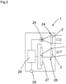
- FIG 2 shows an optoelectronic sensor 1 with at least one glass lens 2.
- the optoelectronic sensor 1 can be, for example, a triangulation sensor or triangulation button.
- the optoelectronic sensor 1 has a light transmitter 25 with laser illumination and a transmitter lens 24 in order to generate a light spot on an object.
- the received light is a Receiving lens 26 directed to a spatially resolving receiver 27 and imaged there, for example.
- the distance of the object can be determined by means of a control and evaluation unit 28 and an object detection signal or a distance signal can be output at an output 29 .
- the transmitting lens 24 and/or receiving lens 26 can be formed by the glass lens 2 .
- Lenses of other optoelectronic sensors 1, such. B. light barriers, distance sensors, color sensors, contrast sensors, light grids or similar sensors can have a glass lens 2 according to the invention.
- figure 3 1 shows an example of the injection mold 6 for a glass lens 2.
- this consists of at least two parts, each of which provides a part of the injection mold 6 for the glass lens 2.
- a vent opening or vent openings, not shown, are also provided and present.
- the glass lens 2 can preferably be in accordance with figure 4 be a spherical glass lens 2. At least one optically active surface is spherical.
- the glass lens 2 has at least one flat lateral surface 30 .
- the glass lens 2 can be made more compact since the glass lens 2 is limited laterally.
- the glass lens 2 has two opposite flat lateral surfaces.
- the associated injection mold 6 has a contour or shape for the at least one flat lateral surface 30 .
- the glass lens 2 has at least one capture or centering contour 9 .
- the catch or centering contour 9 serves to center and/or fix the glass lens 2 .
- the associated injection mold 6 has a contour or shape for the at least one catching or centering contour 9 .
- the glass lens 2 has at least one catch or centering pin 10 .
- the catch or centering pin 10 serves to center and/or fix the glass lens 2 .
- the associated injection mold 6 has a contour or shape for the at least one pilot or centering pin 10 .
- the glass lens 2 has at least one undercut 11 .
- the undercut 11 can, for example, improve the attachment or centering of the glass lens 2 .
- the associated injection mold 6 has a contour or shape for the at least one undercut 11, with a slide being provided in order to demould the glass lens 2.
- the glass lens 2 has at least one stepped structure 19 .
- the stepped structure 19 can improve the attachment or centering of the glass lens 2, for example.
- the associated injection mold has a contour or shape for the at least one stepped structure 19 .
- the glass lens 2 is a double lens 12, the two glass lenses 2 of the double lenses 12 being connected to one another via integral lateral webs 13, with an opening 14 being present between the glass lenses 2 and between the webs 13.
- the double lens 12 is thus formed in one piece and the two glass lenses 2 of the double lens 12 are already aligned with one another and defined in their position with respect to one another as a result of the manufacturing process.
- the associated injection mold has a contour or shape for the double lens 12 .
- the glass lens 2 has at least one thread 20 .
- the glass lens 2 is according to figure 13 shown in a side view and in a front view.
- the glass lens 2 can be fastened or centered, for example, by means of the thread 20 .
- the associated injection mold has a contour or shape for the thread 20, namely, for example, an unscrewing core which is unscrewed from the injection mold after the glass/binder body 7 has cooled.
- the glass lens 2 has an opening 15 along the optical axis 21 .
- the glass lens 2 is according to figure 14 shown in a side view and a front view.
- An autocollimation sensor can thus be implemented in which the optical axis of the transmitter and the optical axis of the receiver coincide.
- the light beam from the transmitter is guided through the opening in the glass lens.
- the injection mold has a contour or shape for the opening.
- the glass lens 2 has at least one refractive structure 16 and at least one diffractive structure 17 .
- the diffractive structure 17 has a structure size of up to 1 ⁇ m, for example.
- a first side or a front side of the glass lens 2 has at least the refractive structure 16 and a second side or a back side of the glass lens 2 has at least the diffractive structure 17 .
- a glass lens 2 with only diffractive structures 17 according to figure 16 or also a glass lens 2 with only refractive structures 16 according to FIG figure 17 are made and formed.
- the injection mold has a contour or shape for the at least one refractive structure 16 and/or the at least one diffractive structure 17.
- the glass lens 2 has a water-repellent surface 18 or hydrophobic surface with low wettability.
- the hydrophobic or superhydrophobic surface is water-repellent due to the nature of the surface.
- the surface forms arched elevations that are about 10 to 20 micrometers high and 10 to 15 micrometers apart, which means that the surface tension of water is maintained and the water droplets roll off. As a result, water no longer has the opportunity to get into the gaps between the elevations, with the result that the contact area between water and the surface is significantly reduced.
- the glass lens has several zones 22 with different focal lengths.
- the zones 22 are annularly arranged with a central circular inner zone 22 surrounded by the annular zones 22 . In this way, better detection results can be achieved for a distance sensor, for example in the close range and in the far range.
- the zones 22 can also be arranged in sections one after the other.
- the zones 22 can also be arranged in sections one after the other.
- an elongated glass lens 2 For example, with an elongated glass lens 2.
- the glass lens 2 is a complex glass lens or a free-form lens 23.
- a free-form lens 23 in the case of a free-form lens 23 for one
- desired lighting pattern or lighting forms are generated. For example, linear or oval-shaped lighting spots.
- different reception intensities or different reception light forms can be generated, in particular for location-resolving reception elements or line reception elements or array reception elements of triangulation light sensors.
Abstract
Optolektronischer Sensor (1), Glaslinse (2) und Verfahren zur Herstellung mindestens einer Glaslinse (2), wobei mindestens kristalline Glaspulverpartikel (3) oder Quarzglaspulverpartikel mit einem organischen Bindemittel (4) gemischt werden, die Glas-/Bindemittelmischung (5) aus mindestens Glaspulverpartikel (3) und organischem Bindemittel (4) erhitzt wird bis diese teigig oder flüssig ist, eine Spritzgussform (6) für die Glas-/Bindemittelmischung (5) ebenfalls erhitzt wird, die Glas-/Bindemittelmischung (5) mittels Druck in die Spritzgussform (6) gespritzt wird, die Spritzgussform (6) mit der Glas-/Bindemittelmischung (5) abgekühlt wird, der nach dem Abkühlen entstandene feste Glas-/Bindemittelkörper (7) entformt wird, dem Glas-/Bindemittelkörper (7) das Bindemittel (4) durch Entbindern entzogen wird, und der verbleibende Glaskörper (8) gesintert wird, wodurch nach dem Sintern die Glaslinse (2) gebildet ist.

Description
Die vorliegende Erfindung betrifft ein Verfahren zur Herstellung mindestens einer Glaslinse gemäß dem Oberbegriff von Anspruch 1, eine Glaslinse gemäß dem Oberbegriff von Anspruch 4, sowie einen optoelektronischen Sensor gemäß dem Oberbegriff von Anspruch 17.The present invention relates to a method for producing at least one glass lens according to the preamble of claim 1, a glass lens according to the preamble of
Die
Die
Eine Technik, die zum Formen von Glas und Glaskeramik zu komplexen Formen nützlich ist, ist das Pulverspritzgießen. Beim Pulverspritzgießen wird ein Pulver mit einem Polymerbindemittel gemischt und die Mischung wird dann spritzgegossen. Nach dem Entformen wird der resultierende Artikel gelöst und gesintert. Eine hohe Pulverbeladung (hoher Pulveranteil und niedriger Bindemittelanteil) ist wünschenswert, um eine übermäßige Porosität, Verformung und ein übermäßiges Schrumpfen des fertigen Teils zu vermeiden. Während das Pulverspritzgießen in großem Umfang auf die Metallumformung und bis zu einem gewissen Grad bei keramischen Umformprozessen angewendet wurde, wurde dem Pulverspritzgießen von Materialien auf Glasbasis wenig Aufmerksamkeit geschenkt. Dies kann daran liegen, dass Glaspulverpartikel typischerweise ziemlich unregelmäßig sind, während die allgemein verstandene ideale Partikelform für das Pulverspritzgießen kugelförmig mit einem geringen Aspektverhältnis ist, um die Fließ- und Packungsfähigkeiten der Pulver- und Bindemittelmischung zu maximieren.One technique useful for forming glass and glass-ceramics into complex shapes is powder injection molding. In powder injection molding, a powder is mixed with a polymer binder and the mixture is then injection molded. After demolding, the resulting article is released and sintered. A high powder loading (high powder content and low binder content) is desirable to avoid excessive porosity, warping and shrinkage of the finished part. While powder injection molding has been widely applied to metal forming and to some extent ceramic forming processes, little attention has been paid to powder injection molding of glass-based materials. This may be because glass powder particles are typically quite irregular, while the commonly understood ideal particle shape for powder injection molding is spherical with a low aspect ratio to maximize the flow and packing capabilities of the powder and binder mixture.
Die
Das Verfahren gemäß der
In der ersten Stufe wird Silikapulver mit einer Bindemittelsubstanz gemischt, um eine Mischung zu erhalten, die für einen Spritzgussvorgang geeignet ist. Beispielsweise ist eine solche Bindemittelsubstanz Polyethylen, das mit Polyethylenglykol gemischt ist. Es wurde herausgefunden, dass das Mischen gleicher Volumina einer solchen Bindemittelsubstanz und eines Siliciumdioxidpulvers ein Material ergibt, das zu einem Produkt von relativ komplexer Form spritzgegossen werden kann.In the first stage, silica powder is mixed with a binder substance to obtain a mixture suitable for injection molding. For example, one such binder substance is polyethylene mixed with polyethylene glycol. It has been found that mixing equal volumes of such a binder substance and a silica powder results in a material that can be injection molded into a product of relatively complex shape.
Nach dem Spritzgussvorgang wird die Bindemittelsubstanz aus dem Material des geformten Produkts entfernt. Abhängig von der Art der Bindemittelsubstanz kann diese Entfernung durch Erhitzen des Produkts und / oder durch einen anderen Vorgang oder Prozess erfolgen. In derzweiten Stufe wird nach dem Entfernen der Bindemittelsubstanz das Material des geformten Produkts durch Erhitzen des Materials gesintert, so dass das endgültige Quarzglasprodukt erhalten wird.After the injection molding process, the binder substance is removed from the material of the molded product. Depending on the nature of the binder substance, this removal can be done by heating the product and/or by some other operation or process. In the second stage, after removing the binder substance, the material of the molded product is sintered by heating the material so that the final quartz glass product is obtained.
Eine Aufgabe der Erfindung besteht darin, eine Glaslinse mit einer hohen Oberflächengüte herzustellen. Weiter besteht die Aufgabe darin eine Glaslinse und einen optoelektronischen Sensor bereitzustellen.An object of the invention is to produce a glass lens with a high surface quality. Another object is to provide a glass lens and an optoelectronic sensor.
Die Aufgabe wird gemäß Anspruch 1 gelöst durch ein Verfahren zur Herstellung mindestens einer Glaslinse, wobei mindestens kristalline Glaspulverpartikel oder Quarzglaspulverpartikel mit einem organischen Bindemittel gemischt werden, die Glas-/Bindemittelmischung aus mindestens Glaspulverpartikel und organischem Bindemittel erhitzt wird bis diese teigig oder flüssig ist, eine Spritzgussform für die Glas-/Bindemittelmischung ebenfalls erhitzt wird, die Glas-/Bindemittelmischung mittels Druck in die Spritzgussform gespritzt wird, die Spritzgussform mit der Glas-/Bindemittelmischung abgekühlt wird, der nach dem Abkühlen entstandene feste Glas-/Bindemittelkörper entformt wird, dem Glas-/Bindemittelkörper das Bindemittel durch Entbindern entzogen wird, der verbleibende Glaskörper gesintert wird, wodurch nach dem Sintern die Glaslinse gebildet ist.The object is achieved according to claim 1 by a method for producing at least one glass lens, wherein at least crystalline glass powder particles or quartz glass powder particles are mixed with an organic binder, the glass/binder mixture of at least glass powder particles and organic binder is heated until it is pasty or liquid, a injection mold for the glass/binder mixture is also heated, the glass/binder mixture is injected into the injection mold by means of pressure, the injection mold with the glass/binder mixture is cooled, the solid glass/binder body produced after cooling is demolded, the glass -/binder body the binder is removed by debinding, the remaining glass body is sintered, whereby the glass lens is formed after sintering.
Gemäß der Erfindung werden Glaslinsen im Spritzgussprozess hergestellt. Nach dem Entbinde- und Sinterprozess besitzt die Glaslinse bereits Oberflächen mit einer hohen Oberflächengüte, so dass keine Nacharbeit mehr erforderlich ist und die Glaslinse direkt in einem optischen System verwendet werden kann.According to the invention, glass lenses are produced in an injection molding process. After the debinding and sintering process, the glass lens already has surfaces with a high surface quality, so that no further reworking is required and the glass lens can be used directly in an optical system.
Die vorliegende Erfindung umfasst eine Glaslinse, wobei die Glaslinse mittels einem Verfahren nach mindestens einem der Ansprüche 1 bis 3 hergestellt ist.The present invention comprises a glass lens, the glass lens being manufactured by a method according to at least one of claims 1 to 3.
Die vorliegende Erfindung umfasst einen optoelektronischen Sensor mit einer Glaslinse nach mindestens einem der Ansprüche 4 bis 16.The present invention comprises an optoelectronic sensor with a glass lens according to at least one of
Die Glaslinse weist vorteilhaft keine Spannungsdoppelbrechung auf. Herkömmliche Glaslinsen erhalten durch den Abkühlprozess nach dem Pressen eine innere Spannung. Diese Spannung zeigt sich durch eine Spannungsdoppelbrechung, die polarisiertes Licht zu einem gewissen Maß depolarisiert. Häufig nutzen optoelektronische Sensoren für ihre Funktion, wie z. B. Reflexionslichtschranken polarisiertes Licht. Herkömmliche Glaslinsen für Polarisationsanwendungen müssen nachteilig nach dem ersten Abkühlprozess erhitzt und dann über einen längeren zeitlichen Vorgang kontrolliert abgekühlt werden, was auch als Feinkühlen bezeichnet wird.The glass lens advantageously has no stress birefringence. Conventional glass lenses are internally stressed as a result of the cooling process after pressing. This strain manifests itself as a strain birefringence that depolarizes polarized light to some extent. Often use optoelectronic sensors for their function, such. B. Reflection light barriers polarized light. Conventional glass lenses for polarization applications disadvantageously have to be heated after the first cooling process and then cooled down in a controlled manner over a longer period of time, which is also referred to as fine cooling.
Beim vorliegenden Glasspritzguss erhält man direkt nach dem erfindungsgemäßen Herstellungsverfahren spannungsfreie Glaslinsen.In the case of the present glass injection molding, stress-free glass lenses are obtained directly after the production method according to the invention.
Da bei der vorliegenden Glaslinse fast keine Nacharbeit, wie beispielsweise Polieren oder Schleifen mehr notwendig ist, sind diese zum einen kostengünstiger und es entsteht weniger Ausschuss durch Bruch, da die risikobehaftete Nacharbeit entfällt.Since almost no rework, such as polishing or grinding, is necessary with the present glass lens, these are more cost-effective and there is less waste due to breakage, since the risky rework is no longer necessary.
Somit können Oberflächen der Glaslinse gebildet werden mit einem Mittenrauwert von ca. kleiner 0,4 µm, bevorzugt bis ca. kleiner 0,2 µm und besonders bevorzugt bis kleiner 0,1 µm.In this way, surfaces of the glass lens can be formed with an average roughness value of approximately less than 0.4 μm, preferably up to approximately less than 0.2 μm and particularly preferably up to less than 0.1 μm.
Die Glas-/Bindemittelmischung und die Spritzgussform werden gleichmäßig erwärmt und dann wird die Glas-/Bindemittelmischung in die Spritzgussform gespritzt.The glass/binder mixture and the injection mold are evenly heated and then the glass/binder mixture is injected into the injection mold.
Das Ausgangsmaterial besteht aus Glaspulverpartikeln oder Quarzglaspulverpartikeln bzw. Siliziumoxidpulverpartikeln und einem organischen Bindemittel, dass die Verbindung zwischen den Partikeln herstellt.The starting material consists of glass powder particles or quartz glass powder particles or silicon oxide powder particles and an organic binder that creates the connection between the particles.
Die Glaspulverpartikel werden sehr fein, nämlich in Größen im nm-Bereich mit dem organischen Bindemittel gemischt. Dadurch entsteht bereits bei der Mischung ein sehr feines Pulvergemisch, wodurch in der Schmelze, also im teigigen oder flüssigen Zustand der Glas-/Bindemittelmischung eine homogene Mischung gebildet wird.The glass powder particles are very finely mixed with the organic binder in sizes in the nm range. As a result, a very fine powder mixture is created during the mixing process, which means that a homogeneous mixture is formed in the melt, i.e. in the pasty or liquid state of the glass/binder mixture.
Beim Entbindern wird der Glas-/Bindemittelmischung des Glas-/Bindemittelkörpers das organische Bindemittel entzogen. Dazu wird der Glas-/Bindemittelkörper soweit erhitzt, dass das Bindemittel entweichen kann. Um die Struktur des verbleibenden Glaskörpers während des Entbinderns zu erhalten sind ggf. weitere Formen vorgesehen, die das Entweichen des Bindemittels ermöglichen.During debinding, the organic binder is removed from the glass/binder mixture of the glass/binder body. To do this, the glass/binder body is heated to such an extent that the binder can escape. In order to preserve the structure of the remaining glass body during debinding, additional molds are provided, if necessary, which allow the binder to escape.
Im anschließenden Sinterprozess wird der Glaskörper umgangssprachlich gebacken, so dass eine Porosität des Glaskörpers verschwindet und ein homogener einstückiger Glaskörper als Glaslinse entsteht, wobei die Glaspulverpartikel nahezu vollständig verschmelzen.In the subsequent sintering process, the glass body is colloquially baked, so that porosity in the glass body disappears and a homogeneous one-piece glass body is created as a glass lens, with the glass powder particles merging almost completely.
Sowohl beim Entbindern, wie auch beim Sintern schrumpft die Glaslinse auf die gewünschten finalen Abmessungen. Der Grand der Schrumpfung kann beispielsweise 10 bis 30 Volumen-% betragen und wird im Wesentlichen durch das Mischungsverhältnis der Glas-/Bindemittelmischung bestimmt. Der Grad der Schrumpfung wird daher bereits bei der Konstruktion der Form und der Größe der Spritzgussform berücksichtigt. Die beim Mischen entstehenden Agglomerate werden damit im Sinterprozess zu Glas ohne Fehlstellen (ohne Gefügeauflockerung). Fehlstellen nach dem Sinterprozess würde bedeuten, dass die opt. Funktion der Glaslinse beeinträchtigt wird. Diese Fehlstellen werden jedoch gemäß der vorliegenden Erfindung vermieden.Both during debinding and during sintering, the glass lens shrinks to the desired final dimensions. The degree of shrinkage can be, for example, 10 to 30% by volume and is essentially determined by the mixing ratio of the glass/binder mixture. The degree of shrinkage is therefore already taken into account in the design of the mold and the size of the injection mold. The agglomerates created during mixing become glass without defects (without structural loosening) in the sintering process. Defects after the sintering process would mean that the opt. function of the glass lens is impaired. However, these defects are avoided according to the present invention.
Das Verhindern der Fehlstellen hängt teilweise vom Mischungsverhältnis von Glaspulverpartikeln und dem organischen Bindemittel ab. Wichtig ist auch die chem. Verbindung und Anordnung zwischen Glaspulverpartikel und Bindemittel.The prevention of voids depends in part on the mixing ratio of glass powder particles and the organic binder. The chemistry is also important. Connection and arrangement between glass powder particles and binder.
Das Entbindern und Sintern kann unabhängig getrennt nacheinander erfolgen oder aber auch gleichzeitig in einem Prozess-Schritt.Debinding and sintering can be carried out separately one after the other, or simultaneously in one process step.
Bei der Glaslinse kann es sich vorzugsweise um eine sphärische Glaslinse handeln. Dabei ist mindestens eine optisch aktive Fläche sphärisch. Das heißt, diese Fläche ist ein Oberflächenausschnitt einer Kugel.The glass lens can preferably be a spherical glass lens. At least one optically active surface is spherical. That is, this area is a surface section of a sphere.
Es können auch bi-konvexe, plan-konvexe, konkav-konvexe, konvex-konkave, plan-konkave oder bi-konkave oder ähnliche Glaslinsen hergestellt werden. Weiter können auch asphärische Glaslinsen hergestellt werden, je nach gewünschtem Anwendungsfall des optoelektronischen Sensors. Es können Glaslinsen mit einer hohen Funktionsdichte bzw. eine Mehrfunktionenglaslinse bereitgestellt werden.Bi-convex, plano-convex, concave-convex, convex-concave, plano-concave or bi-concave or similar glass lenses can also be produced. Furthermore, aspheric glass lenses can also be produced, depending on the desired application of the optoelectronic sensor. Glass lenses with a high functional density or a multifunctional glass lens can be provided.
In Weiterbildung der Erfindung weist das organische Bindemittel Polyacetat, Polyoxymethylen und/oder Wachs aufIn a development of the invention, the organic binder contains polyacetate, polyoxymethylene and/or wax
Polyacetat und Polyoxymethylen sind hochmolekulare thermoplastische Kunststoffe. Die farblosen, teilkristallinen Polymere werden zur Herstellung der Glaslinsen im Spritzgußverfahren verwendet. Wegen der hohen Steifigkeit, niedrigen Reibwerten und guter Dimensionsstabilitäten werden Polyoxymethylene für die Herstellung der Präzisionsteile, wie der vorliegenden Glaslinse eingesetzt. Alternativ oder zusätzlich kann auch Wachs als Bestandteil des organischen Bindemittels vorgesehen sein.Polyacetate and polyoxymethylene are high-molecular thermoplastics. The colorless, semi-crystalline polymers are used to manufacture the glass lenses using the injection molding process. Because of the high rigidity, low coefficient of friction and good dimensional stability, polyoxymethylenes are used to manufacture precision parts such as the present glass lens. Alternatively or additionally, wax can also be provided as a component of the organic binder.
In Weiterbildung der Erfindung weist die Glas-/Bindemittelmischung mindestens 40 Volumen-%, mindestens 50 Volumen-%, mindestens 60 Volumen-% oder mindestens 65 Volumen-% Glaspulverpartikel oder Quarzglaspartikel auf.In a development of the invention, the glass/binder mixture has at least 40% by volume, at least 50% by volume, at least 60% by volume or at least 65% by volume of glass powder particles or quartz glass particles.
Je höher der Anteil an Glaspulverpartikel oder Quarzglaspartikel ist, desto einfacher ist es die Genauigkeit der hergestellten Glaslinse zu erzeugen bzw. zu gewährleisten, da eine gute Formleistung aufrechterhalten wird und da eine Schrumpfprozess beim Entbindern minimiert ist. Gemäß der Erfindung können auch noch höhere Anteile von Glaspulverpartikel oder Quarzglaspartikel vorgesehen sein, von mindestens 70 Volumen-%, oder mindestens 75 Volumen-%. Je höher der Anteil der Glaspulverpartikel ist desto kompakter und damit formstabiler ist ein gebildeter Glas-/Bindemittelkörper, welcher auch als ,Grünling' bezeichnet wird, welcher anschließend entbunden und gesintert wird. Jedoch muss auch genügend Bindemittel vorhanden sein, um die Glaspulverpartikel miteinander ausreichend formstabil zu verbinden.The higher the proportion of glass powder particles or quartz glass particles, the easier it is to produce or ensure the accuracy of the manufactured glass lens, since good molding performance is maintained and since shrinkage during debinding is minimized. According to the invention, even higher proportions of glass powder particles or quartz glass particles can be provided, of at least 70% by volume, or at least 75% by volume. The higher the proportion of glass powder particles, the more compact and thus more dimensionally stable is a formed glass/binder body, which is also referred to as a 'green body', which is then debound and sintered. However, sufficient binder must also be present in order to connect the glass powder particles to one another with sufficient dimensional stability.
In Weiterbildung der Erfindung weist die Glaslinse mindestens eine ebene seitlich Fläche auf. Dadurch kann die Glaslinse kompakter hergestellt werden, da die Glaslinse seitlich begrenzt ist. Beispielsweise weist die Glaslinse zwei gegenüberliegende ebene seitliche Flächen auf, wodurch die Glaslinse noch kompakter ausgebildet ist. Die ebene seitliche Fläche wird direkt beim Herstellungsverfahren bzw. beim Herstellungsprozess gebildet. Es ist kein nachfolgender Bearbeitungsschritt erforderlich. Die Spritzgussform weist eine Kontur bzw. Form für die mindestens eine ebene seitliche Fläche auf.In a development of the invention, the glass lens has at least one flat lateral surface. As a result, the glass lens can be made more compact since the glass lens is laterally limited. For example, the glass lens has two opposite flat lateral surfaces, as a result of which the glass lens is designed to be even more compact. The flat lateral surface is formed directly during the manufacturing method or during the manufacturing process. No subsequent processing step is required. The injection mold has a contour or shape for the at least one flat lateral surface.
In Weiterbildung der Erfindung weist die Glaslinse mindestens eine Fang- oder Zentrierkontur auf. Die Fang- oder Zentrierkonturen dienen dazu die Glaslinse zu zentrieren und/oder zu fixieren. Dadurch, dass die Glaslinse die Fang- oder Zentrierkontur aufweist kann die Glaslinse kompakter hergestellt werden. Die Fang- oder Zentrierkontur wird direkt beim Herstellungsverfahren bzw. beim Herstellungsprozess gebildet. Es ist kein nachfolgender Bearbeitungsschritt erforderlich. Die Spritzgussform weist eine Kontur bzw. Form für die mindestens eine Fang- oder Zentrierkontur auf.In a development of the invention, the glass lens has at least one catching or centering contour. The catch or centering contours serve to center and/or fix the glass lens. Because the glass lens has the capture or centering contour, the glass lens can be made more compact. The catching or centering contour is formed directly during the manufacturing process. No subsequent processing step is required. The injection mold has a contour or shape for the at least one catching or centering contour.
In Weiterbildung der Erfindung weist die Glaslinse mindestens einen Fang- oder Zentrierstift auf. Der Fang- oder Zentrierstift dienen dazu die Glaslinse zu zentrieren und/oder zu fixieren. Dadurch, dass die Glaslinse den Fang- oder Zentrierstift aufweist kann die Glaslinse kompakter hergestellt werden. Der Fang- oder Zentrierstift wird direkt beim Herstellungsverfahren bzw. beim Herstellungsprozess gebildet. Es ist kein nachfolgender Bearbeitungsschritt erforderlich. Die Spritzgussform weist eine Kontur bzw. Form für den mindestens eine Fang- oder Zentrierstift auf.In a development of the invention, the glass lens has at least one catch or centering pin. The catch or centering pin are used to center and/or fix the glass lens. Because the glass lens has the catch or centering pin, the glass lens can be made more compact. The pilot or centering pin is formed directly during the manufacturing process. No subsequent processing step is required. The injection mold has a contour or shape for the at least one pilot or centering pin.
In Weiterbildung der Erfindung weist die Glaslinse mindestens einen Hinterschnitt auf. Der Hinterschnitt kann beispielsweise die Befestigung bzw. Zentrierung der Linse verbessern. Der Hinterschnitt wird direkt beim Herstellungsverfahren bzw. beim Herstellungsprozess gebildet. Es ist kein nachfolgender Bearbeitungsschritt erforderlich. Die Spritzgussform weist eine Kontur bzw. Form für den mindestens einen Hinterschnitt auf.In a development of the invention, the glass lens has at least one undercut. The undercut can, for example, improve the attachment or centering of the lens. The undercut is formed directly during the manufacturing process. No subsequent processing step is required. The injection mold has a contour or shape for the at least one undercut.
In Weiterbildung der Erfindung weist die Glaslinse mindestens eine stufige Struktur auf. Die stufige Struktur kann beispielsweise die Befestigung bzw. Zentrierung der Linse verbessern. Beispielsweise rasten Schnapphaken eines Aufnahmekörpers in die stufige Struktur ein. Die stufige Struktur wird direkt beim Herstellungsverfahren bzw. beim Herstellungsprozess gebildet. Es ist kein nachfolgender Bearbeitungsschritt erforderlich. Die Spritzgussform weist eine Kontur bzw. Form für die mindestens einen stufige Struktur auf.In a development of the invention, the glass lens has at least one stepped structure. The stepped structure can, for example, improve the attachment or centering of the lens. For example, snap hooks of a receiving body snap into the stepped structure. The stepped structure is formed directly during the manufacturing method or during the manufacturing process. No subsequent processing step is required. The injection mold has a contour or shape for the at least one stepped structure.
In Weiterbildung der Erfindung ist die Glaslinse eine Doppellinse, wobei die zwei Glaslinsen der Doppellinsen über einstückige seitliche Stege miteinander verbunden sind, wobei zwischen den Glaslinsen und zwischen den Stegen ein Durchbruch vorhanden ist. In dem Durchbruch kann eine optische Blende angeordnet sein, um eine optische Isolierung zwischen den Glaslinsen zu verbessern. Damit ist die Doppellinse einstückig ausgebildet und die zwei Linsen der Doppellinse sind bereits durch den Herstellungsprozess zueinander ausgerichtet und in ihrer Lage zueinander definiert. Die Doppellinse wird direkt beim Herstellungsverfahren bzw. beim Herstellungsprozess gebildet. Es ist kein nachfolgender Bearbeitungsschritt erforderlich. Die Spritzgussform weist eine Kontur bzw. Form für die Doppellinse auf.In a development of the invention, the glass lens is a double lens, the two glass lenses of the double lenses being connected to one another via integral lateral webs, with an opening being present between the glass lenses and between the webs. An optical screen can be arranged in the aperture in order to improve optical isolation between the glass lenses. The double lens is thus formed in one piece and the two lenses of the double lens are already aligned with one another and defined in their position with respect to one another as a result of the manufacturing process. The double lens is formed directly during the manufacturing process. No subsequent processing step is required. The injection mold has a contour or shape for the double lens.
In Weiterbildung der Erfindung weist die Glaslinse mindestens ein Gewinde auf. Mittels des Gewindes kann beispielsweise eine Befestigung bzw. Zentrierung der Linse erfolgen. Das Gewinde wird direkt beim Herstellungsverfahren bzw. beim Herstellungsprozess gebildet. Es ist kein nachfolgender Bearbeitungsschritt erforderlich. Die Spritzgussform weist eine Kontur bzw. Form für das Gewinde auf, nämlich beispielsweise einen Ausdrehkern der nach dem Erkalten des Glas-/Bindemittelkörpers aus der Spritzgussform herausgedreht wird.In a development of the invention, the glass lens has at least one thread. The lens can be fastened or centered, for example, by means of the thread. The thread is formed directly during the manufacturing process. No subsequent processing step is required. The injection mold has a contour or shape for the thread, namely, for example, an unscrewing core which is unscrewed from the injection mold after the glass/binder body has cooled.
In Weiterbildung der Erfindung weist die Glaslinse eine Öffnung entlang der optischen Achse auf. Damit kann ein Autokollimationssensor realsiert werden bei dem die optische Achse des Senders und die optische Achse des Empfängers zusammenfallen. Dabei wird der Lichtstrahl des Senders durch die Öffnung der Glaslinse geführt. Die Öffnung wird direkt beim Herstellungsverfahren bzw. beim Herstellungsprozess gebildet. Es ist kein nachfolgender Bearbeitungsschritt erforderlich. Die Spritzgussform weist eine Kontur bzw. Form für die Öffnung auf.In a development of the invention, the glass lens has an opening along the optical axis. An autocollimation sensor can thus be implemented in which the optical axis of the transmitter and the optical axis of the receiver coincide. The light beam from the transmitter is guided through the opening in the glass lens. The opening is formed directly during the manufacturing method or during the manufacturing process. No subsequent processing step is required. The injection mold has a contour or shape for the opening.
In Weiterbildung der Erfindung weist die Glaslinse mindestens eine refraktive und/oder mindestens eine diffraktive Struktur auf. Die diffraktive Struktur hat beispielsweise eine Strukturgröße von bis zu 1 µm.In a development of the invention, the glass lens has at least one refractive and/or at least one diffractive structure. The diffractive structure has a structure size of up to 1 μm, for example.
Es kann beispielsweise eine Glaslinse mit nur diffraktiven Strukturen oder auch eine Glaslinse mit nur refraktiven Strukturen hergestellt und gebildet werden.For example, a glass lens with only diffractive structures or also a glass lens with only refractive structures can be produced and formed.
Jedoch sind ebenso Glaslinsen vorgesehen mit einer mindestens einer refraktiven und mindestens eine diffraktive Struktur. Beispielsweise weist eine erste Seite bzw. eine Vorderseite der Glaslinse mindestens die refraktive Struktur auf und eine zweite Seite bzw. eine Rückseite der Glaslinse mindestens die diffraktive Struktur auf.However, glass lenses are also provided with at least one refractive and at least one diffractive structure. For example, a first side or a front side of the glass lens has at least the refractive structure and a second side or a back side of the glass lens has at least the diffractive structure.
Die mindestens eine refraktive Struktur und/oder mindestens eine diffraktive Struktur wird direkt beim Herstellungsverfahren bzw. beim Herstellungsprozess gebildet. Es ist kein nachfolgender Bearbeitungsschritt erforderlich. Die Spritzgussform weist eine Kontur bzw. Form für die mindestens eine refraktive und/oder die mindestens eine diffraktive Struktur auf.The at least one refractive structure and/or at least one diffractive structure is formed directly during the manufacturing method or during the manufacturing process. No subsequent processing step is required. The injection mold has a contour or shape for the at least one refractive and/or the at least one diffractive structure.
In Weiterbildung der Erfindung weist die Glaslinse eine wasserabweisende Oberfläche bzw. hydrophobe Oberfläche mit einer geringen Benetzbarkeit auf. Die hydrophobe oder superhydrophobe Oberfläche ist aufgrund der Oberflächenbeschaffenheit wasserabweisend.In a development of the invention, the glass lens has a water-repellent surface or hydrophobic surface with low wettability. The hydrophobic or superhydrophobic surface is water-repellent due to the nature of the surface.
Beispielsweise bildet die Oberfläche etwa 10 bis 20 Mikrometer hohe und 10 bis 15 Mikrometer voneinander entfernte gewölbte Erhebungen, welche dazu führen, dass die Oberflächenspannung von Wasser erhalten bleibt und die Wassertröpfchen abperlen. Somit hat Wasser nicht mehr die Möglichkeit, in die Zwischenräume der Erhebungen zu gelangen, was zur Folge hat, dass sich die Kontaktfläche zwischen Wasser und Oberfläche erheblich verringert.For example, the surface forms arched elevations that are about 10 to 20 micrometers high and 10 to 15 micrometers apart, which means that the surface tension of water is maintained and the water droplets roll off. As a result, water no longer has the opportunity to get into the gaps between the elevations, with the result that the contact area between water and the surface is significantly reduced.
Die Hydrophobie von Oberflächen wird über den Kontaktwinkel bestimmt. Je höher der Kontaktwinkel, desto hydrophober die Oberfläche. Oberflächen mit einem Kontaktwinkel <90° werden als hydrophil, solche mit einem Kontaktwinkel >90° als hydrophob bezeichnet. Gemäß der vorliegenden Erfindung können Kontaktwinkel von bis zu 160° (Superhydrophobie) erreicht werden. Das bedeutet, dass nur etwa 2 bis 3 % der Tropfenoberfläche mit der Oberfläche der Glaslinse in Kontakt stehen, diese also eine extrem geringe Benetzbarkeit besitzt. Die Adhäsion zwischen Glaslinsenoberfläche und Wassertropfen ist dabei so gering, dass das Wasser leicht abperlen kann. Aufliegende Schmutzpartikel, die ebenfalls nur eine kleine Kontaktfläche besitzen, werden dadurch mitgeführt und weggespült. Selbst hydrophobe Schmutzpartikel werden von der Glaslinsenoberfläche abgewaschen, weil deren Adhäsion zur Glaslinsenoberfläche geringer ist als zum Wassertropfen.The hydrophobicity of surfaces is determined via the contact angle. The higher the contact angle, the more hydrophobic the surface. Surfaces with a contact angle <90° are called hydrophilic, those with a contact angle >90° are called hydrophobic. According to the present invention, contact angles of up to 160° (superhydrophobicity) can be achieved. This means that only about 2 to 3% of the droplet surface is in contact with the surface of the glass lens, which means that it has extremely low wettability. The adhesion between the surface of the glass lens and the drop of water is so low that the water can easily roll off. Overlying dirt particles, which also only have a small contact surface, are carried along and washed away. Even hydrophobic dirt particles are washed off the glass lens surface because their adhesion to the glass lens surface is lower than to water drops.
In Weiterbildung der Erfindung weist die Glaslinse mehrere Zonen mit unterschiedlichen Brennweiten auf. Beispielsweise sind die Zonen ringförmig angeordnet mit einer zentralen kreisförmigen inneren Zone, welche von den ringförmigen Zonen umgeben ist. Damit können bessere Detektionsergebnisse für einen Distanzsensor beispielsweise im Nahbereich und im Fernbereich erzielt werden.In a further development of the invention, the glass lens has a number of zones with different focal lengths. For example, the zones are annularly arranged with a central circular inner zone surrounded by the annular zones. In this way, better detection results can be achieved for a distance sensor, for example in the close range and in the far range.
Jedoch können die Zonen auch abschnittsförmig nacheinander angeordnet sein. Beispielsweise bei einer länglich ausgebildeten Glaslinse.However, the zones can also be arranged in sections one after the other. For example, with an elongated glass lens.
In Weiterbildung der Erfindung ist die Glaslinse eine Freiformlinse. Mit einer Freiformlinse können im Falle einer Freiformlinse für einen Lichtsender gewünschte Beleuchtungsmuster bzw. Beleuchtungsformen erzeugt werden. Beispielsweise linienförmige oder ovalförmige Beleuchtungsspots oder auch eine hellere Beleuchtung zu den Bildrändern hin um einem empfängerseitigen Randlichtabfall, der Vignettierung, entgegen zu wirken. Im Falle einer Freiformlinse für einen Lichtempfänger können insbesondere für ortsaufösende Empfangselemente bzw. Zeilenempfangselemente oder Arrayempfangselemente von Triangulationslichttastern unterschiedliche Empfangsintensitäten bzw. unterschiedliche Empfangslichtformen erzeugt werden.In a development of the invention, the glass lens is a free-form lens. In the case of a free-form lens for a light transmitter, desired illumination patterns or forms of illumination can be generated with a free-form lens. For example, linear or oval-shaped lighting spots or also brighter lighting towards the edges of the image in order to counteract a fall in light at the edge of the receiver, i.e. vignetting. In the case of a free-form lens for a light receiver, different reception intensities or different reception light forms can be generated, in particular for spatially resolving reception elements or line reception elements or array reception elements of triangulation light sensors.
Die Erfindung wird nachstehend auch hinsichtlich weiterer Vorteile und Merkmale unter Bezugnahme auf die beigefügte Zeichnung anhand von Ausführungsbeispielen erläutert. Die Figuren der Zeichnung zeigen in:
- Figur 1a bis 1i
- ein Verfahren zur Herstellung mindestens einer Glaslinse;
Figur 2- einen optoelektronischen Sensor;
Figur 3- eine Spritzgussform;
Figur 4- eine sphärische Glaslinse;
Figur 5- eine bi-konvexe Glaslinse;
Figur 6 und 7- jeweils eine konkav-konvexe Glaslinse;
Figur 8- eine Glaslinse mit seitlich ebenen Flächen;
- Figur 9
- eine Glaslinse mit mindestens einer Fang- oder Zentrierkontur;
Figur 10- eine Glaslinse mit einem Hinterschnitt;
Figur 11- eine Glaslinse mit einer stufigen Struktur;
Figur 12- eine Glaslinse welche als Doppellinse ausgebildet ist;
Figur 13- eine Glaslinse mit einem Gewinde;
Figur 14- eine Glaslinse mit einer Öffnung;
Figur 15- eine Glaslinse mit einer refraktiven Struktur und einer diffraktiven Struktur;
Figur 16- eine Glaslinse mit einer diffraktiven Struktur;
Figur 17- eine Glaslinse mit einer refraktiven Struktur;
Figur 18- eine Glaslinse mit einer wasserabweisenden Oberfläche 18;
Figur 19- eine Glaslinse mit mehreren Zonen;
Figur 20- eine komplexe Glaslinse bzw. eine Freiformglaslinse.
- Figure 1a to 1i
- a method of manufacturing at least one glass lens;
- figure 2
- an optoelectronic sensor;
- figure 3
- an injection mold;
- figure 4
- a spherical glass lens;
- figure 5
- a bi-convex glass lens;
- Figure 6 and 7
- each a concavo-convex glass lens;
- figure 8
- a glass lens with laterally flat surfaces;
- figure 9
- a glass lens with at least one capture or centering contour;
- figure 10
- a glass lens with an undercut;
- figure 11
- a glass lens with a stepped structure;
- figure 12
- a glass lens which is designed as a double lens;
- figure 13
- a glass lens with a thread;
- figure 14
- a glass lens with an aperture;
- figure 15
- a glass lens having a refractive structure and a diffractive structure;
- figure 16
- a glass lens with a diffractive structure;
- figure 17
- a glass lens with a refractive structure;
- figure 18
- a glass lens with a water-
repellent surface 18; - figure 19
- a multi-zoned glass lens;
- figure 20
- a complex glass lens or a free form glass lens.
In den nachfolgenden Figuren sind identische Teile mit identischen Bezugszeichen versehen.In the following figures, identical parts are provided with identical reference numbers.
Gemäß
Gemäß
Die Glas-/Bindemittelmischung 5 aus mindestens Glaspulverpartikel 3 und organischem Bindemittel 4 wird gemäß
Eine Spritzgussform 6 gemäß
Gemäß
Die Spritzgussform 6 mit der Glas-/Bindemittelmischung 5 wird gemäß
Der nach dem Abkühlen entstandene feste Glas-/Bindemittelkörper 7 wurde gemäß Figur 1g entformt. Hierzu ist beispielsweise eine Entformvorrichtung vorgesehen.The solid glass/
Gemäß
Nachdem der verbleibende Glaskörper 8 gemäß
Gemäß
Beim vorliegenden Glasspritzguss erhält man direkt nach dem erfindungsgemäßen Herstellungsverfahren spannungsfreie Glaslinsen 2.In the case of the present glass injection molding, stress-
Bei der vorliegenden Glaslinse 2 ist fast keine Nacharbeit oder gar keine Nacharbeit, wie beispielsweise Polieren oder Schleifen mehr notwendig ist.With the
Somit können Oberflächen der Glaslinse 2 gebildet werden mit einem Mittenrauwert von ca. kleiner 0,4 µm, bevorzugt bis ca. kleiner 0,2 µm und besonders bevorzugt bis kleiner 0,1 µm.Thus, surfaces of the
Die Glas-/Bindemittelmischung 5 und die Spritzgussform 6 werden gemäß
Das Ausgangsmaterial besteht aus Glaspulverpartikeln 3 oder Quarzglaspulverpartikeln bzw. Siliziumoxidpulverpartikeln und einem organischen Bindemittel 4, dass die Verbindung zwischen den Partikeln herstellt.The starting material consists of
Die Glaspulverpartikel 3 werden sehr fein, nämlich in Größen im nm-Bereich mit dem organischen Bindemittel 4 gemischt gemäß
Gemäß
Gemäß
Gemäß der Erfindung können auch noch höhere Anteile von Glaspulverpartikel 3 oder Quarzglaspartikel vorgesehen sein, von mindestens 70 Volumen-%, oder mindestens 75 Volumen-%.According to the invention, even higher proportions of
Je höher der Anteil der Glaspulverpartikel 3 ist desto kompakter und damit formstabiler ist ein gebildeter Glas-/Bindemittelkörper 7 gemäß
Beim Entbindern gemäß
Im anschließenden Sinterprozess bzw. Sinterverfahren gemäß
Sowohl beim Entbindern, wie auch beim Sintern schrumpft die Glaslinse 2 auf die gewünschten finalen Abmessungen. Der Grand der Schrumpfung kann beispielsweise 10 bis 30 Volumen-% betragen und wird im Wesentlichen durch das Mischungsverhältnis der Glas-/Bindemittelmischung 5 bestimmt. Der Grad der Schrumpfung wird daher bereits bei der Konstruktion der Spritzgussform und der Größe der Spritzgussform berücksichtigt.The
Das Entbindern und Sintern kann unabhängig getrennt nacheinander erfolgen oder aber auch gleichzeitig in einem Prozess-Schritt.Debinding and sintering can be carried out separately one after the other, or simultaneously in one process step.
Bei der Glaslinse 2 kann es sich vorzugsweise gemäß
Es können auch bi-konvexe gemäß
Gemäß
Gemäß
Gemäß
Gemäß
Gemäß
Gemäß
Gemäß
Gemäß
Gemäß
Es kann beispielsweise eine Glaslinse 2 mit nur diffraktiven Strukturen 17 gemäß
Gemäß
Beispielsweise bildet die Oberfläche etwa 10 bis 20 Mikrometer hohe und 10 bis 15 Mikrometer voneinander entfernte gewölbte Erhebungen, welche dazu führen, dass die Oberflächenspannung von Wasser erhalten bleibt und die Wassertröpfchen abperlen. Somit hat Wasser nicht mehr die Möglichkeit, in die Zwischenräume der Erhebungen zu gelangen, was zur Folge hat, dass sich die Kontaktfläche zwischen Wasser und Oberfläche erheblich verringert.For example, the surface forms arched elevations that are about 10 to 20 micrometers high and 10 to 15 micrometers apart, which means that the surface tension of water is maintained and the water droplets roll off. As a result, water no longer has the opportunity to get into the gaps between the elevations, with the result that the contact area between water and the surface is significantly reduced.
Gemäß
Jedoch können die Zonen 22 auch abschnittsförmig nacheinander angeordnet sein. Beispielsweise bei einer länglich ausgebildeten Glaslinse 2.However, the
Gemäß
- 11
- optoelektronischer Sensoroptoelectronic sensor
- 22
- Glaslinseglass lens
- 33
- Glaspulverpartikelglass powder particles
- 44
- organisches Bindemittelorganic binder
- 55
- Glas-/Bindemittelmischungglass/binder mixture
- 66
- Spritzgussforminjection mold
- 77
- Glas-/Bindemittelkörperglass/binder body
- 88th
- Glaskörpervitreous
- 99
- Fang- oder ZentrierkonturenCatching or centering contours
- 1010
- Fang- oder ZentrierstiftePilot or centering pins
- 1111
- Hinterschnittundercut
- 1212
- Doppellinsedouble lens
- 1313
- seitliche Stegeside bars
- 1414
- Durchbruchbreakthrough
- 1515
- Öffnungopening
- 1616
- refraktive Strukturrefractive structure
- 1717
- diffraktive Strukturdiffractive structure
- 1818
- wasserabweisende Oberflächewater-repellent surface
- 1919
- stufige Strukturtiered structure
- 2020
- Gewindethread
- 2121
- optische Achseoptical axis
- 2222
- Zonenzones
- 2323
- Freiformlinsefreeform lens
- 2424
- Senderlinsetransmitter lens
- 2525
- Lichtsenderlight transmitter
- 2626
- Empfangslinsereceiving lens
- 2727
- ortsauflösender Empfängerlocation-resolving receiver
- 2828
- Steuer- und AuswerteeinheitControl and evaluation unit
- 2929
- Ausgangexit
- 3030
- seitliche Flächelateral surface
Claims (17)
Applications Claiming Priority (1)
| Application Number | Priority Date | Filing Date | Title |
|---|---|---|---|
| DE102020120565.1A DE102020120565A1 (en) | 2020-08-04 | 2020-08-04 | Photoelectric sensor, glass lens and method of making a glass lens |
Publications (1)
| Publication Number | Publication Date |
|---|---|
| EP3950609A1 true EP3950609A1 (en) | 2022-02-09 |
Family
ID=76920558
Family Applications (1)
| Application Number | Title | Priority Date | Filing Date |
|---|---|---|---|
| EP21185293.4A Pending EP3950609A1 (en) | 2020-08-04 | 2021-07-13 | Optoelectronic sensor, glass lens and method for manufacturing a glass lens |
Country Status (2)
| Country | Link |
|---|---|
| EP (1) | EP3950609A1 (en) |
| DE (1) | DE102020120565A1 (en) |
Citations (5)
| Publication number | Priority date | Publication date | Assignee | Title |
|---|---|---|---|---|
| JPH04349130A (en) * | 1991-05-27 | 1992-12-03 | Nitto Chem Ind Co Ltd | Production of quartz glass molded body |
| WO2004085322A1 (en) | 2003-03-24 | 2004-10-07 | Koninklijke Philips Electronics N.V. | A method of manufacturing silica glass parts for lamp assemblies |
| WO2007079001A1 (en) | 2005-12-31 | 2007-07-12 | Corning Incorporated | Powder injectionmolding method of glass and glass-ceramics |
| WO2011132753A1 (en) * | 2010-04-21 | 2011-10-27 | 旭硝子株式会社 | Method for producing glass member, and planar lens and glass paste |
| DE102014113854A1 (en) | 2014-09-24 | 2016-03-24 | Ev Group E. Thallner Gmbh | Method for producing a glass optical element |
Family Cites Families (2)
| Publication number | Priority date | Publication date | Assignee | Title |
|---|---|---|---|---|
| DE4338807C1 (en) | 1993-11-12 | 1995-01-26 | Heraeus Quarzglas | Moulding having a high content of silicon dioxide, and process for the production of such mouldings |
| US20060162382A1 (en) | 2004-12-30 | 2006-07-27 | Hrdina Kenneth E | Method and apparatus for producing oxide particles via flame |
-
2020
- 2020-08-04 DE DE102020120565.1A patent/DE102020120565A1/en active Pending
-
2021
- 2021-07-13 EP EP21185293.4A patent/EP3950609A1/en active Pending
Patent Citations (5)
| Publication number | Priority date | Publication date | Assignee | Title |
|---|---|---|---|---|
| JPH04349130A (en) * | 1991-05-27 | 1992-12-03 | Nitto Chem Ind Co Ltd | Production of quartz glass molded body |
| WO2004085322A1 (en) | 2003-03-24 | 2004-10-07 | Koninklijke Philips Electronics N.V. | A method of manufacturing silica glass parts for lamp assemblies |
| WO2007079001A1 (en) | 2005-12-31 | 2007-07-12 | Corning Incorporated | Powder injectionmolding method of glass and glass-ceramics |
| WO2011132753A1 (en) * | 2010-04-21 | 2011-10-27 | 旭硝子株式会社 | Method for producing glass member, and planar lens and glass paste |
| DE102014113854A1 (en) | 2014-09-24 | 2016-03-24 | Ev Group E. Thallner Gmbh | Method for producing a glass optical element |
Non-Patent Citations (2)
| Title |
|---|
| F. KOTZ ET AL.: "Glassomer-Processing Fused Silica Glass Like a Polymer", ADVANCED MATERIALS, vol. 30, no. 22, 1707100, 2018, pages 1 - 5, XP055478935, DOI: 10.1002/adma.201707100 * |
| F. KOTZ ET AL.: "High-throughput thermal replication of transparent fused silica glass", MICROFLUIDICS, BIOMEMS, AND MEDICAL MICROSYSTEMS XVII, SPIE BIOS, SAN FRANCISCO, vol. 10875, 1087503, 2019, pages 1 - 6, XP060119554, DOI: 10.1117/12.2506155 * |
Also Published As
| Publication number | Publication date |
|---|---|
| DE102020120565A1 (en) | 2022-02-10 |
Similar Documents
| Publication | Publication Date | Title |
|---|---|---|
| EP1645545B1 (en) | Process for making lenses and tool for pressing a glass blank | |
| EP1584863B1 (en) | Lighting device with lens and method of fabricating for such | |
| DE2712437C2 (en) | Mold made of thermoplastic material for the manufacture of contact lenses | |
| DE112007002504B4 (en) | Headlight lens for a motor vehicle headlight | |
| EP1593656A1 (en) | Method and Apparatus for Producing an Optical Element | |
| DE102004020363A1 (en) | Method for producing a master, master and method for producing optical elements and optical element | |
| DE3402648A1 (en) | MOLDING DEVICE FOR AN OPTICAL ELEMENT | |
| DE3443607A1 (en) | METHOD FOR PRODUCING OPTICAL LENSES | |
| DE112013006145B4 (en) | Process for the production of a molded glass body and mold | |
| WO2017102443A1 (en) | Method for producing a micro-lens array | |
| DE102005063276B4 (en) | Method for producing glass components with a structured surface | |
| DE4017541C2 (en) | ||
| EP3950609A1 (en) | Optoelectronic sensor, glass lens and method for manufacturing a glass lens | |
| DE60210798T2 (en) | CASTING HOLES AND CASTING FOR THE PRODUCTION OF CONTACT LENSES | |
| DE4102059C2 (en) | Mold for use in the manufacture of lenses | |
| EP0043475B1 (en) | Method of making an integrated micro-optical device to be used with multimode light fibres | |
| EP1432656A1 (en) | Method and device for shaping a structured body and body produced according to said method | |
| WO2010017979A1 (en) | Method and device for the production of a structured object, and structured object | |
| EP3632662B1 (en) | Devices and method for providing lenses for motor vehicle headlamps, fresnel lenses for motor vehicle headlights | |
| DE102006001790A1 (en) | Process to manufacture small optical lens for use in e.g. cell phone by melting glass fiber in two-part shell form | |
| DE19602736A1 (en) | Method and device for producing optical lenses and optical lens arrays | |
| EP4031502A1 (en) | Three-dimensionally formed thin sheet glass | |
| WO2002012586A1 (en) | METHOD FOR PRODUCING A TOOL WHICH CAN BE USED TO CREATE SURFACE STRUCTURES IN THE SUB-νM RANGE | |
| EP2247541B1 (en) | Device for producing objects made of glass by hot forming, and production method | |
| AT523356B1 (en) | PROCESS FOR MANUFACTURING AT LEAST ONE OPTICAL LENS |
Legal Events
| Date | Code | Title | Description |
|---|---|---|---|
| PUAI | Public reference made under article 153(3) epc to a published international application that has entered the european phase |
Free format text: ORIGINAL CODE: 0009012 |
|
| STAA | Information on the status of an ep patent application or granted ep patent |
Free format text: STATUS: THE APPLICATION HAS BEEN PUBLISHED |
|
| AK | Designated contracting states |
Kind code of ref document: A1 Designated state(s): AL AT BE BG CH CY CZ DE DK EE ES FI FR GB GR HR HU IE IS IT LI LT LU LV MC MK MT NL NO PL PT RO RS SE SI SK SM TR |
|
| STAA | Information on the status of an ep patent application or granted ep patent |
Free format text: STATUS: REQUEST FOR EXAMINATION WAS MADE |
|
| 17P | Request for examination filed |
Effective date: 20220712 |
|
| RBV | Designated contracting states (corrected) |
Designated state(s): AL AT BE BG CH CY CZ DE DK EE ES FI FR GB GR HR HU IE IS IT LI LT LU LV MC MK MT NL NO PL PT RO RS SE SI SK SM TR |
|
| STAA | Information on the status of an ep patent application or granted ep patent |
Free format text: STATUS: EXAMINATION IS IN PROGRESS |
|
| 17Q | First examination report despatched |
Effective date: 20230823 |