EP3950607B1 - Feeding system, and glass production apparatus having same - Google Patents
Feeding system, and glass production apparatus having same Download PDFInfo
- Publication number
- EP3950607B1 EP3950607B1 EP19921915.5A EP19921915A EP3950607B1 EP 3950607 B1 EP3950607 B1 EP 3950607B1 EP 19921915 A EP19921915 A EP 19921915A EP 3950607 B1 EP3950607 B1 EP 3950607B1
- Authority
- EP
- European Patent Office
- Prior art keywords
- flange
- subsection
- feeding system
- connection position
- cap
- Prior art date
- Legal status (The legal status is an assumption and is not a legal conclusion. Google has not performed a legal analysis and makes no representation as to the accuracy of the status listed.)
- Active
Links
Images


Classifications
-
- C—CHEMISTRY; METALLURGY
- C03—GLASS; MINERAL OR SLAG WOOL
- C03B—MANUFACTURE, SHAPING, OR SUPPLEMENTARY PROCESSES
- C03B3/00—Charging the melting furnaces
- C03B3/02—Charging the melting furnaces combined with preheating, premelting or pretreating the glass-making ingredients, pellets or cullet
-
- C—CHEMISTRY; METALLURGY
- C03—GLASS; MINERAL OR SLAG WOOL
- C03B—MANUFACTURE, SHAPING, OR SUPPLEMENTARY PROCESSES
- C03B3/00—Charging the melting furnaces
-
- C—CHEMISTRY; METALLURGY
- C03—GLASS; MINERAL OR SLAG WOOL
- C03B—MANUFACTURE, SHAPING, OR SUPPLEMENTARY PROCESSES
- C03B1/00—Preparing the batches
-
- B—PERFORMING OPERATIONS; TRANSPORTING
- B01—PHYSICAL OR CHEMICAL PROCESSES OR APPARATUS IN GENERAL
- B01F—MIXING, e.g. DISSOLVING, EMULSIFYING OR DISPERSING
- B01F35/00—Accessories for mixers; Auxiliary operations or auxiliary devices; Parts or details of general application
- B01F35/181—Preventing generation of dust or dirt; Sieves; Filters
- B01F35/184—Preventing generation of dust
-
- B—PERFORMING OPERATIONS; TRANSPORTING
- B01—PHYSICAL OR CHEMICAL PROCESSES OR APPARATUS IN GENERAL
- B01F—MIXING, e.g. DISSOLVING, EMULSIFYING OR DISPERSING
- B01F35/00—Accessories for mixers; Auxiliary operations or auxiliary devices; Parts or details of general application
- B01F35/71—Feed mechanisms
- B01F35/717—Feed mechanisms characterised by the means for feeding the components to the mixer
- B01F35/718—Feed mechanisms characterised by the means for feeding the components to the mixer using vacuum, under pressure in a closed receptacle or circuit system
-
- B—PERFORMING OPERATIONS; TRANSPORTING
- B08—CLEANING
- B08B—CLEANING IN GENERAL; PREVENTION OF FOULING IN GENERAL
- B08B15/00—Preventing escape of dirt or fumes from the area where they are produced; Collecting or removing dirt or fumes from that area
-
- B—PERFORMING OPERATIONS; TRANSPORTING
- B08—CLEANING
- B08B—CLEANING IN GENERAL; PREVENTION OF FOULING IN GENERAL
- B08B15/00—Preventing escape of dirt or fumes from the area where they are produced; Collecting or removing dirt or fumes from that area
- B08B15/002—Preventing escape of dirt or fumes from the area where they are produced; Collecting or removing dirt or fumes from that area using a central suction system, e.g. for collecting exhaust gases in workshops
-
- B—PERFORMING OPERATIONS; TRANSPORTING
- B65—CONVEYING; PACKING; STORING; HANDLING THIN OR FILAMENTARY MATERIAL
- B65G—TRANSPORT OR STORAGE DEVICES, e.g. CONVEYORS FOR LOADING OR TIPPING, SHOP CONVEYOR SYSTEMS OR PNEUMATIC TUBE CONVEYORS
- B65G69/00—Auxiliary measures taken, or devices used, in connection with loading or unloading
- B65G69/18—Preventing escape of dust
- B65G69/181—Preventing escape of dust by means of sealed systems
- B65G69/182—Preventing escape of dust by means of sealed systems with aspiration means
-
- B—PERFORMING OPERATIONS; TRANSPORTING
- B65—CONVEYING; PACKING; STORING; HANDLING THIN OR FILAMENTARY MATERIAL
- B65G—TRANSPORT OR STORAGE DEVICES, e.g. CONVEYORS FOR LOADING OR TIPPING, SHOP CONVEYOR SYSTEMS OR PNEUMATIC TUBE CONVEYORS
- B65G69/00—Auxiliary measures taken, or devices used, in connection with loading or unloading
- B65G69/18—Preventing escape of dust
- B65G69/181—Preventing escape of dust by means of sealed systems
- B65G69/183—Preventing escape of dust by means of sealed systems with co-operating closure members on each of the parts of a separable transfer channel
-
- F—MECHANICAL ENGINEERING; LIGHTING; HEATING; WEAPONS; BLASTING
- F16—ENGINEERING ELEMENTS AND UNITS; GENERAL MEASURES FOR PRODUCING AND MAINTAINING EFFECTIVE FUNCTIONING OF MACHINES OR INSTALLATIONS; THERMAL INSULATION IN GENERAL
- F16L—PIPES; JOINTS OR FITTINGS FOR PIPES; SUPPORTS FOR PIPES, CABLES OR PROTECTIVE TUBING; MEANS FOR THERMAL INSULATION IN GENERAL
- F16L23/00—Flanged joints
- F16L23/003—Auxiliary devices
-
- B—PERFORMING OPERATIONS; TRANSPORTING
- B01—PHYSICAL OR CHEMICAL PROCESSES OR APPARATUS IN GENERAL
- B01F—MIXING, e.g. DISSOLVING, EMULSIFYING OR DISPERSING
- B01F35/00—Accessories for mixers; Auxiliary operations or auxiliary devices; Parts or details of general application
- B01F35/30—Driving arrangements; Transmissions; Couplings; Brakes
- B01F2035/35—Use of other general mechanical engineering elements in mixing devices
- B01F2035/351—Sealings
-
- B—PERFORMING OPERATIONS; TRANSPORTING
- B08—CLEANING
- B08B—CLEANING IN GENERAL; PREVENTION OF FOULING IN GENERAL
- B08B2215/00—Preventing escape of dirt or fumes from the area where they are produced; Collecting or removing dirt or fumes from that area
- B08B2215/003—Preventing escape of dirt or fumes from the area where they are produced; Collecting or removing dirt or fumes from that area with the assistance of blowing nozzles
Definitions
- the present invention relates to a feeding system and a glass production apparatus having the feeding system.
- a large quantity of various powdered raw materials are loaded into multiple material tanks according to the production formula, and then the powdered raw materials in the material tanks are fed into a mixing tank in specified proportions.
- a blower mounted on the material tank may be utilized to discharge air outwards, so as to maintain a negative pressure in the material tank.
- the device for blending pulverized fuel ash and cement comprises a metering tank, a primary mixing tank, a batch mixing tank, a dust removing tank, dust removers, a fan, a pulverized fuel ash tank, a cement tank, a fished product bin, a pressure air tank, pneumatic adjusting valves, a sampling ball valve, a stop valve and a safety valve, wherein the pressure air tank is connected with the bottoms and lateral portions of the metering tank, the primary mixing tank and the batch mixing tank; the pulverized fuel ash tank is connected with the bottom of the metering tank, the bottom of the cement tank and the bottom of the metering tank are connected with the bottom of the primary mixing tank, and the bottom of the finished product bin and the bottom of the primary mixing tank are connected with the bottom of the batch mixing tank; the top of the metering tank, the top of the primary mixing tank and the top of
- the air discharged by the blower contains a large amount of dust, and the working environment and the physical health of the workers will be severely harmed if the dust-containing air is discharged into the blending room.
- the present invention provides a feeding system and a glass production apparatus having the feeding system.
- the present invention provides a feeding system, which comprises: a plurality of material tanks, each of which has an air outlet; a plurality of blowers, having air inlets in communication with air outlets of the material tanks in one-to-one correspondence; a dust remover, having an air inlet; and a connecting pipe, having a first end in communication with the air inlet of the dust remover and a second end movably arranged between a first connection position and a second connection position, wherein, at the first connection position, the second end is connected with the air outlet of one of the plurality of blowers; at the second connection position, the second end is connected with the air outlet of another one of the plurality of blowers.
- the feeding system according to the embodiments of the present invention has the advantages of simple structure and zero dust leakage.
- the connecting pipe comprises: a first connecting section, having a first end in communication with the air inlet of the dust remover; a telescopic section arranged telescopically, having a first end connected with a second end of the first connecting section; and a second connecting section, having a first end connected with a second end of the telescopic section and a second end movably arranged between the first connection position and the second connection position, wherein, at the first connection position, the second end of the second connecting section is connected with the air outlet of one of the plurality of blowers; at the second connection position, the second end of the second connecting section is connected with the air outlet of another one of the plurality of blowers.
- the first connecting section comprises: a first connecting subsection arranged vertically, having a first end connected with the air inlet of the dust remover; a second connecting subsection, having a second end connected with the first end of the telescopic section and a first end vertically arranged and rotatably connected with the second end of the first connecting subsection, wherein the rotation axis of the first end of the second connecting subsection extends in the vertical direction; preferably the second connecting subsection is an elbow, more preferably the second connecting subsection is a 90-degree elbow; preferably the first end of the second connecting subsection is provided with a first flange, the second end of the first connecting subsection is provided with a second flange, a first gasket is provided between the first flange and the second flange, the connecting pipe further comprises a lock cap sleeved on the first flange and the second flange, and a second gasket is provided between the lock cap and the first flange, wherein the lock cap comprises a first sub-cap and a second sub
- the telescopic section comprises: a first subsection arranged horizontally, having a first end connected with the second end of the first connecting section; and a second subsection arranged horizontally, having a second end connected with the first end of the second connecting section and a first end rotatably connected with the second end of the first subsection with respect to the second end of the first subsection, wherein the rotation axis of the first end of the second subsection extends in the vertical direction.
- the telescopic section further comprises a third connecting subsection having a first end connected with the second end of the first subsection and a second end vertically arranged; and a fourth connecting subsection having a first end vertically arranged and rotatably connected with the second end of the third connecting subsection with respect to the second end of the third connecting subsection and a second end connected with the first end of the second connecting subsection, wherein the rotation axis of the first end of the fourth connecting subsection extends in the vertical direction; preferably each of the third connecting subsection and the fourth connecting subsection is an elbow, more preferably each of the third connecting subsection and the fourth connecting subsection is a 90-degree elbow; preferably the first end of the fourth connecting subsection is provided with a first flange, the second end of the third connecting subsection is provided with a second flange, a first gasket is provided between the first flange and the second flange, the connecting pipe further comprises a lock cap sleeved on the first flange and the second flange, and a second gasket is provided between
- the second connecting section is rotatably arranged, and the rotation axis of the second connecting section extends in the horizontal direction; preferably the first end of the second connecting section is rotatably connected with the second end of the telescopic section, and the rotation axis of the first end of the second connecting section extends in the horizontal direction; preferably the first end of the second connecting section is provided with a first flange, the second end of the telescopic section is provided with a second flange, a first gasket is provided between the first flange and the second flange, the connecting pipe further comprises a lock cap sleeved on the first flange and the second flange, and a second gasket is provided between the lock cap and the first flange, wherein the lock cap comprises a first sub-cap and a second sub-cap, which are connected with each other by fasteners.
- the second connecting section comprises a fifth connecting subsection having a first end connected with the second end of the telescopic section and a second end arranged vertically; and a sixth connecting subsection having a first end vertically arranged and rotatably connected with the second end of the fifth connecting subsection and a second end movably arranged between the first connection position and the second connection position, wherein the rotation axis of the first end of the sixth connecting subsection extends in the vertical direction; preferably each of the fifth connecting subsection and the sixth connecting subsection is an elbow, more preferably each of the fifth connecting subsection and the sixth connecting subsection is a 90-degree elbow; preferably the first end of the sixth connecting subsection is provided with a first flange, the second end of the fifth connecting subsection is provided with a second flange, a first gasket is provided between the first flange and the second flange, the connecting pipe further comprises a lock cap sleeved on the first flange and the second flange, and a second gasket is provided between the lock cap and the first
- the second end of the connecting pipe is arranged horizontally, and a volute casing of each of the plurality of blowers has an air discharge portion arranged horizontally, which has a free end defining the air outlet of the blower, wherein, at the first connection position, the second end is connected with the free end of one of the plurality of blowers; at the second connection position, the second end is connected with the free end of another one of the plurality of blowers.
- the connecting pipe further comprises a connecting shackle, which comprises: a manipulating portion hinged to the second end of the connecting pipe; and a hook portion having a first end connected with the manipulating portion, wherein, when the second end of the connecting pipe is at the first connection position or the second connection position, the third flange is fitted with the fourth flange on the corresponding blower, and the second end of the hook portion hooks the fourth flange, so as to press the fourth flange on the third flange.
- a connecting shackle which comprises: a manipulating portion hinged to the second end of the connecting pipe; and a hook portion having a first end connected with the manipulating portion, wherein, when the second end of the connecting pipe is at the first connection position or the second connection position, the third flange is fitted with the fourth flange on the corresponding blower, and the second end of the hook portion hooks the fourth flange, so as to press the fourth flange on the third flange.
- the present invention provides a glass production apparatus, which comprises: the feeding system according to the first aspect of the present invention; a mixing tank, having a feed inlet in communication with a discharge outlet of each of the material tanks of the feeding system; and a kiln, having a feed inlet in communication with a discharge outlet of the mixing tank.
- the glass production apparatus has the advantages of simple structure and zero dust leakage.
- Each material tank 20 has an air outlet, and the dust remover has an air inlet.
- the air inlets of the plurality of blowers 30 are in communication with the air outlets of the material tanks 20 in one-to-one correspondence. That is to say, the number of the blowers 30 may be equal to the number of the material tanks 20, and the air inlet of each blower 30 is in communication with the air outlet of one material tank 20.
- the first end of the connecting pipe 10 is in communication with the air inlet of the dust remover, and the second end 140 of the connecting pipe 10 is movably arranged between a first connection position and a second connection position, wherein, at the first connection position, the second end 140 of the connecting pipe 10 is connected with the air outlet 312 of one of the plurality of blowers 30; at the second connection position, the second end 140 of the connecting pipe 10 is connected with the air outlet 312 of another one of the plurality of blowers 30.
- the second end 140 of the connecting pipe 10 is switchably connected to any one of the plurality of blowers 30.
- the second end 140 of the connecting pipe 10 is connected to the air outlet 312 of the blower 30 in communication with the air outlet of the material tank 20 first.
- the blower 30 is started to maintain a negative pressure in the material tank 20. In view that the air discharged by the blower 30 contains a large amount of dust, it may be discharged through the connecting pipe 10 into the dust remover.
- the second end 140 of the connecting pipe 10 may be connected to the air outlet 312 of the blower 30 in communication with the air outlet of another material tank 20 before the powdered raw material is loaded to said another material tank 20.
- the blower 30 is started to maintain a negative pressure in said another material tank 20.
- the air discharged by the blower 30 contains a large amount of dust, it may be discharged through the connecting pipe 10 into the dust remover.
- the connecting pipe 10 may cooperate with a plurality of material tanks 20 and a plurality of blowers 30, so that a plurality of blowers 30 can share the same connecting pipe 10.
- the structure of the feeding system 1 can be simplified, i.e., it is unnecessary to provide a separate connecting pipe 10 connected to the dust remover for each blower 30. Therefore, even if the working space (blending room) of the feeding system 1 is narrow, the blower 30 that will discharge dust-containing air can be connected with the connecting pipe 10, so as to avoid discharging the dust into the blending room. That is to say, the space occupied by the feeding system 1 can be reduced.
- a plurality of blowers 30 can share the connecting pipe 10, so that the dust-containing air discharged by the blowers 30 can enter the dust remover through the connecting pipe 10.
- the feeding system 1 according to the embodiment of the present invention has the advantages of simple structure and zero dust leakage, etc.
- the feeding system 1 comprises material tanks 20, blowers 30, a connecting pipe 10 and the dust remover.
- the connecting pipe 10 comprises a first connecting section 110, a telescopic section 120 and a second connecting section 130.
- the first end of the first connecting section 110 is in communication with the air inlet of the dust remover.
- the telescopic section 120 is arranged telescopically, and the first end of the telescopic section 120 is connected with the second end of the first connecting section 110.
- the first end 131 of the second connecting section 130 is connected with the second end 125 of the telescopic section 120, and the second end of the second connecting section 130 is movably arranged between the first connection position and the second connection position, wherein, at the first connection position, the second end 134 of the second connecting section 130 is connected with the air outlet 312 of one of the plurality of blowers 30; at the second connection position, the second end 134 of the second connecting section 130 is connected with the air outlet 312 of another one of the plurality of blowers 30.
- the connecting pipe 10 includes the telescopic section 120, the connecting pipe 10 is also arranged telescopically.
- the second end 140 of the connecting pipe 10 can be connected more conveniently and easily with the blowers 30 at different distances from the dust remover, so that more blowers 30 can share the connecting pipe 10, thereby the structure of the feeding system 1 is further simplified and the space occupied by the feeding system 1 is further reduced.
- the first connecting section 110 may comprise a first connecting subsection 111 and a second connecting subsection 112.
- the first connecting subsection 111 is arranged vertically, which is to say, the first connecting subsection 111 may extend in the vertical direction, and the first end of the first connecting subsection 111 is connected with the air inlet of the dust remover.
- the second end of the second connecting subsection 112 is connected with the first end of the telescopic section 120.
- the first end 1121 of the second connecting subsection 112 is arranged vertically, which is say, the first end 1121 of the second connecting subsection 112 may extend in the vertical direction.
- the first end 1121 of the second connecting subsection 112 is rotatably connected with the second end 1111 of the first connecting subsection 111, and the rotation axis of the first end 1121 of the second connecting subsection 112 extends in the vertical direction.
- the second connecting subsection 112 can drive the telescopic section 120 to rotate around the rotation axis of the first end 1121 of the second connecting subsection 112, so as to further expand the scope of movement of the telescopic section 120 and the connecting pipe 10.
- the second end 140 of the connecting pipe 10 can be connected more conveniently and easily with the blowers 30 at different distances from the dust remover, so that more blowers 30 can share the connecting pipe 10, thereby the structure of the feeding system 1 is further simplified and the space occupied by the feeding system 1 is further reduced.
- the first end 1121 of the second connecting subsection 112 is provided with a first flange 410
- the second end 1111 of the first connecting subsection 111 is provided with a second flange 420
- a first gasket 510 is arranged between the first flange 410 and the second flange 420.
- the connecting pipe 10 further comprises a lock cap 60 sleeved on the first flange 410 and the second flange 420, and a second gasket 520 is arranged between the lock cap 60 and the first flange 410.
- lock cap 60 can abut against (press) the second flange 420 and the second gasket 520, the first flange 410 and the second flange 420 can abut against the first gasket 510, and the first flange 410 can also abut against the second gasket 520.
- the lock cap 60 comprises a first sub-cap 610 and a second sub-cap 620, which are connected with each other by fasteners (not shown in the figures).
- the fasteners may be bolts.
- each of the first sub-cap 610 and the second sub-cap 620 comprises a first pressing portion 611, a second pressing portion 612 and a connecting portion 613.
- the first pressing portion 611 abuts against (presses) the second gasket 520 so as to press the second gasket 520 on the first flange 410, which is to say, the first pressing portion 611 and the first flange 410 sandwich the second gasket 520.
- the second pressing portion 612 abuts against the second flange 420 so that the first flange 410 and the second flange 420 sandwich the first gasket 510.
- the connecting portion 613 is connected with each of the first pressing portion 611 and the second pressing portion 612, and may be located at the outer side of the first flange 410 and the second flange 420, which is to say, the first flange 410 and the second flange 420 are located between the first connecting subsection 111 and the connecting portion 613 in the radial direction of the first connecting subsection 111.
- the connecting pipe 10 may further comprise a pressing ring 150, the lock cap 60 (the first pressing portion 611) may abut against the pressing ring 150, and the pressing ring 150 may abut against the second gasket 520 so as to press the second gasket 520 on the first flange 410, which is to say, the pressing ring 150 and the first flange 410 sandwich the second gasket 520.
- the second connecting subsection 112 is an elbow. More preferably the second connecting subsection 112 is a 90-degree elbow.
- the telescopic section 120 comprises a first subsection 121 and a second subsection 122.
- the first subsection 121 is arranged horizontally and the second subsection 122 is arranged horizontally, which is to say, both the first subsection 121 and the second subsection 122 may extend in the horizontal direction.
- the first end of the first subsection 121 is connected with the second end of the first connecting section 110, and the second end of the second subsection 122 is connected with the first end of the second connecting section 130.
- the first end of the second subsection 122 is rotatably connected with the second end of the first subsection 121 with respect to the second end of the first subsection 121, and the rotation axis of the first end of the second subsection 122 extends in the vertical direction.
- At least one of the first subsection 121 and the second subsection 122 can rotate around the rotation axis of the first end of the second subsection 122, so that the telescopic section 120 can be telescoped more easily and conveniently.
- the telescopic section 120 further comprises a third connecting subsection 123 and a fourth connecting subsection 124, wherein the first end of the third connecting subsection 123 is connected with the second end of the first subsection 121, and the second end of the fourth connecting subsection 124 is connected with the first end of the second subsection 122.
- the second end 1231 of the third connecting subsection 123 is arranged vertically, and the first end 1241 of the fourth connecting subsection 124 is arranged vertically. That is to say, the second end 1231 of the third connecting subsection 123 may extend in the vertical direction, and the first end 1241 of the fourth connecting subsection 124 may extend in the vertical direction.
- the first end 1241 of the fourth connecting subsection 124 is rotatably connected with the second end 1231 of the third connecting subsection 123 with respect to the second end 1231 of the third connecting subsection 123, and the rotation axis of the first end 1241 of the fourth connecting subsection 124 extends in the vertical direction.
- the first end 1241 of the fourth connecting subsection 124 is provided with a first flange 410
- the second end 1231 of the third connecting subsection 123 is provided with a second flange 420
- a first gasket 510 is arranged between the first flange 410 and the second flange 420.
- the connecting pipe 10 further comprises a lock cap 60 sleeved on the first flange 410 and the second flange 420, and a second gasket 520 is arranged between the lock cap 60 and at least one of the first flange 410 and the second flange 420.
- the lock cap 60 can abut against the second gasket 520, the first flange 410 and the second flange 420 can abut against the first gasket 510, and the first flange 410 can also abut against the second gasket 520.
- the lock cap 60 can directly abut against the second flange 420.
- the lock cap 60 comprises a first sub-cap 610 and a second sub-cap 620, which are connected with each other by fasteners (not shown in the figures).
- the pre-tightening force of the lock cap 60 can be adjusted by the fasteners, so that the friction force between any two of the lock cap 60, the first flange 410, the second flange 420, the first gasket 510 and the second gasket 520 that abut against each other can be adjusted.
- each of the first sub-cap 610 and the second sub-cap 620 comprises a first pressing portion 611, a second pressing portion 612 and a connecting portion 613.
- the first pressing portion 611 abuts against (presses) the second gasket 520 so as to press the second gasket 520 on the first flange 410, which is to say, the first pressing portion 611 and the first flange 410 sandwich the second gasket 520.
- the second pressing portion 612 abuts against the second flange 420 so that the first flange 410 and the second flange 420 sandwich the first gasket 510.
- the connecting portion 613 is connected with each of the first pressing portion 611 and the second pressing portion 612, and may be located at the outer side the first flange 410 and the second flange 420, which is to say, the first flange 410 and the second flange 420 are located between the first end 1241 of the fourth connecting subsection 124 (the second end 1231 of the third connecting subsection 123) and the connecting portion 613 in the radial direction of the first end 1241 of the fourth connecting subsection 124 (the radial direction of the second end 1231 of the third connecting subsection 123).
- the connecting pipe 10 may further comprise a pressing ring 150, the lock cap 60 (the first pressing portion 611) may abut against the pressing ring 150, and the pressing ring 150 may abut against the second gasket 520 so as to press the second gasket 520 on the first flange 410, which is to say, the pressing ring 150 and the first flange 410 sandwich the second gasket 520.
- each of the third connecting subsection 123 and the fourth connecting subsection 124 is an elbow, more preferably each of the third connecting subsection 123 and the fourth connecting subsection 124 is a 90-degree elbow.
- the second connecting section 130 is arranged rotatably, and the rotation axis of the second connecting section 130 extends in the horizontal direction.
- the second end 140 of the connecting pipe 10 (the second end 134 of the second connecting section 130) can be moved up and down by rotating the second connecting section 130 around the rotation axis extending in the horizontal direction, wherein the up-down (vertical) direction is indicated by the arrow A in Figs. 1 and 5 .
- the second end 140 of the connecting pipe 10 When the second end 140 of the connecting pipe 10 moves from the first connection position to the second connection position or from the second connection position to the first connection position, the second end 140 of the connecting pipe 10 may be separated from the air outlet 312 of the blower 30 first, and then the second connecting section 130 may be rotated around the rotation axis extending in the horizontal direction to move the second end 140 of the connecting pipe 10 upward.
- the second end 140 of the connecting pipe 10 is moved toward the air outlet 312 of another blower 30.
- the second connecting section 130 may be rotated about a rotation axis extending in the horizontal direction so as to move the second end 140 of the connecting pipe 10 downward.
- the second end 140 of the connecting pipe 10 is connected to the air outlet 312 of said another blower 30.
- the first end 131 of the second connecting section 130 is rotatably connected with the second end 125 of the telescopic section 120, and the rotation axis of the first end 131 of the second connecting section 130 extends in the horizontal direction.
- the structure of the connecting pipe 10 and the feeding system 1 is more reasonable.
- the second connecting section 130 comprises a fifth connecting subsection 132 and a sixth connecting subsection 133, wherein the first end 1321 of the fifth connecting subsection 132 is connected with the second end 125 of the telescopic section 120, and the second end 1332 of the sixth connecting subsection 133 is movably arranged between the first connection position and the second connection position.
- the second end 1332 of the sixth connecting subsection 133 is connected with the air outlet 312 of one of the plurality of blowers 30; at the second connection position, the second end 1332 of the sixth connecting subsection 133 is connected with the air outlet 312 of another one of the plurality of blowers 30.
- the second end 1322 of the fifth connecting subsection 132 is arranged vertically, and the first end 1331 of the sixth connecting subsection 133 is arranged vertically, which is to say, the second end 1322 of the fifth connecting subsection 132 may extend in the vertical direction, and the first end 1331 of the sixth connecting subsection 133 may extend in the vertical direction.
- the first end 1331 of the sixth connecting subsection 133 is rotatably connected with the second end 1322 of the fifth connecting subsection 132, and the rotation axis of the first end 1331 of the sixth connecting subsection 133 extends in the vertical direction.
- the second end 1332 of the sixth connecting subsection 133 When the second end 1332 of the sixth connecting subsection 133 moves from the first connection position to the second connection position or from the second connection position to the first connection position, the second end 1332 of the sixth connecting subsection 133 may be separated from the air outlet 312 of the blower 30 first, and then the second end 1332 of the sixth connecting subsection 133 may be rotated around a rotating axis extending in the vertical direction, so as to prevent the second end 1332 of the sixth connecting subsection 133 from colliding with the blower 30 when the second connecting section 130 is rotated.
- the second connecting section 130 may be rotated first so that the second end 140 of the connecting pipe 10 moves downward, and then the second end 1332 of the sixth connecting subsection 133 may be rotated around a rotation axis extending in the vertical direction so as to accurately adjust the position of the second end 1332 of the sixth connecting subsection 133, thus the second end 1332 of the sixth connecting subsection 133 can be connected to the air outlet 312 of said another blower 30 more conveniently and easily.
- the first end 1331 of the sixth connecting subsection 133 is provided with a first flange 410
- the second end 1322 of the fifth connecting subsection 132 is provided with a second flange 420
- a first gasket 510 is arranged between the first flange 410 and the second flange 420.
- the connecting pipe 10 further comprises a lock cap 60 sleeved on the first flange 410 and the second flange 420, and a second gasket 520 is arranged between the lock cap 60 and the first flange 410.
- the lock cap 60 can abut against (press) the second flange 420 and the second gasket 520, the first flange 410 and the second flange 420 can abut against the first gasket 510, and the first flange 410 can also abut against the second gasket 520.
- the lock cap 60 comprises a first sub-cap 610 and a second sub-cap 620, which are connected with each other by fasteners (not shown in the figures).
- the pre-tightening force of the lock cap 60 can be adjusted by the fasteners, so that the friction force between any two of the lock cap 60, the first flange 410, the second flange 420, the first gasket 510 and the second gasket 520 that abut against each other can be adjusted.
- each of the first sub-cap 610 and the second sub-cap 620 comprises a first pressing portion 611, a second pressing portion 612 and a connecting portion 613.
- the first pressing portion 611 abuts against (presses) the second gasket 520 so as to press the second gasket 520 on the first flange 410, which is to say, the first pressing portion 611 and the first flange 410 sandwich the second gasket 520.
- the second pressing portion 612 abuts against the second flange 420 so that the first flange 410 and the second flange 420 sandwich the first gasket 510.
- the connecting portion 613 is connected with each of the first pressing portion 611 and the second pressing portion 612, and may be located at the outer side the first flange 410 and the second flange 420, which is to say, the first flange 410 and the second flange 420 are located between the first end 1331 of the sixth connecting subsection 133 (the second end 1322 of the fifth connecting subsection 132) and the connecting portion 613 in the radial direction of the first end 1331 of the sixth connecting subsection 133 (the radial direction of the second end 1322 of the fifth connecting subsection 132).
- the connecting pipe 10 may further comprise a pressing ring 150, the lock cap 60 (the first pressing portion 611) may abut against the pressing ring 150, and the pressing ring 150 may abut against the second gasket 520 so as to press the second gasket 520 on the first flange 410, which is to say, the pressing ring 150 and the first flange 410 sandwich the second gasket 520.
- each of the fifth connecting subsection 132 and the sixth connecting subsection 133 is an elbow. More preferably each of the fifth connecting subsection 132 and the sixth connecting subsection 133 is a 90-degree elbow.
- the first end 131 of the second connecting section 130 (the first end 1321 of the fifth connecting subsection 132) is provided with a first flange 410
- the second end 125 of the telescopic section 120 (the second end 1221 of the second subsection 122) is provided with a second flange 420
- a first gasket 510 is arranged between the first flange 410 and the second flange 420.
- the connecting pipe 10 further comprises a lock cap 60 sleeved on the first flange 410 and the second flange 420, and a second gasket 520 is arranged between the lock cap 60 and the first flange 410.
- the lock cap 60 can abut against (press) the second flange 420 and the second gasket 520, the first flange 410 and the second flange 420 can abut against the first gasket 510, and the first flange 410 can also abut against the second gasket 520.
- the lock cap 60 comprises a first sub-cap 610 and a second sub-cap 620, which are connected with each other by fasteners (not shown in the figures).
- the pre-tightening force of the lock cap 60 can be adjusted by the fasteners, so that the friction force between any two of the lock cap 60, the first flange 410, the second flange 420, the first gasket 510 and the second gasket 520 that abut against each other can be adjusted.
- each of the first sub-cap 610 and the second sub-cap 620 comprises a first pressing portion 611, a second pressing portion 612 and a connecting portion 613.
- the first pressing portion 611 abuts against (presses) the second gasket 520 so as to press the second gasket 520 on the first flange 410, which is to say, the first pressing portion 611 and the first flange 410 sandwich the second gasket 520.
- the second pressing portion 612 abuts against the second flange 420 so that the first flange 410 and the second flange 420 sandwich the first gasket 510.
- the connecting portion 613 is connected with each of the first pressing portion 611 and the second pressing portion 612, and may be located at the outer side the first flange 410 and the second flange 420, which is to say, the first flange 410 and the second flange 420 are located between the first end 131 of the second connecting section 130 (the second end 125 of the telescopic section 120) and the connecting portion 613 in the radial direction of the first end 131 of the second connecting section 130 (the radial direction of the second end 125 of the telescopic section 120).
- the connecting pipe 10 may further comprise a pressing ring 150, the lock cap 60 (the first pressing portion 611) may abut against the pressing ring 150, and the pressing ring 150 may abut against the second gasket 520 so as to press the second gasket 520 on the first flange 410, which is to say, the pressing ring 150 and the first flange 410 sandwich the second gasket 520.
- the second end 140 of the connecting pipe 10 (the second end 1332 of the sixth connecting subsection 133) is arranged horizontally, and the volute casing 310 of each blower 30 has an air discharge portion 311 arranged horizontally, which is to say, the second end 140 of the connecting pipe 10 may extend in the horizontal direction, and the air discharge portion 311 may extend in the horizontal direction.
- the free end 3111 of the air discharge portion 311 defines the air outlet 312 of the blower 30.
- the second end 140 of the connecting pipe 10 is connected with the free end 3111 of one of the plurality of blowers 30; at the second connection position, the second end 140 of the connecting pipe 10 is connected with the free end 3111 of another one of the plurality of blowers 30.
- the second end 140 of the connecting pipe 10 is provided with a third flange 430, and the air discharge portion 311 is provided with a fourth flange 440.
- the connecting pipe 10 further comprises a connecting shackle 70, which comprises a manipulating portion 710 and a hook portion 720.
- the manipulating portion 710 is hinged to the second end 140 of the connecting pipe 10, and the first end 721 of the hook portion 720 is connected with the manipulating portion 710.
- the third flange 430 is fitted with the fourth flange 440 on the corresponding blower 30 (directly contact or indirect contact via the third gasket 530), and the second end 722 of the hook portion 720 hooks the fourth flange 440, so as to press the fourth flange 440 on the third flange 430.
- a plurality of connecting shackles 70 may be provided, and the plurality of connecting shackles 70 may be arranged at an interval in the circumferential direction of the second end 140 of the connecting pipe 10.
- the technical scheme of the present application will be further described in an example of an upper connecting shackle 70 in Fig. 5 .
- the lower end of the manipulating portion 710 may be hinged to the second end 140 of the connecting pipe 10.
- the manipulating portion 710 rotates clockwise, the second end 722 of the hook portion 720 moves toward the third flange 430, so as to press the fourth flange 440 on the third flange 430.
- the manipulating portion 710 rotates counterclockwise, the second end 722 of the hook portion 720 moves away from the third flange 430, so that the third flange 430 can be separated from the fourth flange 440.
- the third gasket 530 between the third flange 430 and the fourth flange 440 may be made of rubber, so that the third flange 430 and the fourth flange 440 can be connected together more tightly, and thus leakage of dust-containing gas between the third flange 430 and the fourth flange 440 can be prevented.
- the feeding system 1 may further comprises a first supporting frame 810 and a second supporting frame 820.
- the connecting pipe 10 may be retracted when no powdered raw material is loaded into the material tanks 20.
- the first subsection 121 may be supported on the first supporting frame 810, and the second subsection 122 may be supported on the second supporting frame 820.
- the present invention further provides a glass production apparatus.
- the glass production apparatus according to an embodiment of the present invention comprises a kiln (not shown in the figures), a mixing tank 20, and the feeding system 1 according to the above embodiment of the present invention.
- the feed inlet of the mixing tank 20 is in communication with the discharge outlet of each tank 20 of the feeding system 1, and the feed inlet of the kiln is in communication with the discharge outlet of the mixing tank 20.
- the glass production apparatus according to the embodiment of the present invention has the advantages of simple structure and zero dust leakage.
- orientation or position relations indicated by terms “above”, “below”, “vertical”, “horizontal”, “top”, “bottom”, “clockwise”, “radial”, or “circumferential”, are based on the orientation or position relations indicated in the accompanying drawings. They are used only to ease and simplify the description of the present invention, rather than indicating or implying that the involved device or component must have a specific orientation or must be constructed and operated in a specific orientation.
- first and second are used only for description purpose, and shall not be interpreted as indicating or implying relative importance or implicitly indicating the quantity of the indicated technical feature. Hence, a feature confined by “first” or “second” may explicitly or implicitly comprise at least one such feature. In the description of the present invention, "a plurality of' or “multiple” means at least two, such as two or more, unless otherwise specified explicitly.
- connection may be fixed connection, detachable connection, or integral connection; may be mechanical connection or electrical connection or in communication with each other; may be direct connection or indirect connection via an intermediate medium, or internal communication or interactive relation between two elements unless otherwise defined explicitly.
- install shall be interpreted in their general meaning.
- link may be fixed connection, detachable connection, or integral connection; may be mechanical connection or electrical connection or in communication with each other; may be direct connection or indirect connection via an intermediate medium, or internal communication or interactive relation between two elements unless otherwise defined explicitly.
- a first feature “above” or “below” a second feature may represent that the first feature and the second feature directly contact with each other or the first feature and the second feature contact with each other indirectly via an intermediate medium.
- a first feature “above” or “over” a second feature may represent that the first feature is right above or diagonally above the second feature, or may only represent that the elevation of the first feature is higher than that of the second feature.
- a first feature being “below” or “under” a second feature may represent that the first feature is right below or diagonally below the second feature, or may only represent that the elevation of the first feature is lower than that of the second feature.
Landscapes
- Chemical & Material Sciences (AREA)
- Engineering & Computer Science (AREA)
- Chemical Kinetics & Catalysis (AREA)
- Mechanical Engineering (AREA)
- Organic Chemistry (AREA)
- Materials Engineering (AREA)
- General Engineering & Computer Science (AREA)
- Structures Of Non-Positive Displacement Pumps (AREA)
- Quick-Acting Or Multi-Walled Pipe Joints (AREA)
- Joints Allowing Movement (AREA)
- Refuse Collection And Transfer (AREA)
- Glass Melting And Manufacturing (AREA)
- Mutual Connection Of Rods And Tubes (AREA)
Description
- The present invention relates to a feeding system and a glass production apparatus having the feeding system.
- In the glass manufacturing industry and other industries, a large quantity of various powdered raw materials are loaded into multiple material tanks according to the production formula, and then the powdered raw materials in the material tanks are fed into a mixing tank in specified proportions. In order to prevent unsmooth material loading or even back splashing incurred by air flow disturbance in a material tank when the powdered raw material is loaded into the material tank, a blower mounted on the material tank may be utilized to discharge air outwards, so as to maintain a negative pressure in the material tank.
-
CN108274616A relates to a device for blending pulverized fuel ash and cement. The device for blending pulverized fuel ash and cement comprises a metering tank, a primary mixing tank, a batch mixing tank, a dust removing tank, dust removers, a fan, a pulverized fuel ash tank, a cement tank, a fished product bin, a pressure air tank, pneumatic adjusting valves, a sampling ball valve, a stop valve and a safety valve, wherein the pressure air tank is connected with the bottoms and lateral portions of the metering tank, the primary mixing tank and the batch mixing tank; the pulverized fuel ash tank is connected with the bottom of the metering tank, the bottom of the cement tank and the bottom of the metering tank are connected with the bottom of the primary mixing tank, and the bottom of the finished product bin and the bottom of the primary mixing tank are connected with the bottom of the batch mixing tank; the top of the metering tank, the top of the primary mixing tank and the top of the batch mixing tank are each connected with one dust remover and then connected with the top of the dust removing tank, and the top of the dust removing tank is connected with the fan; and pipeline connection is used as the connection mode. By means of the device for blending pulverized fuel ash and cement, the problem that pulverized fuel ash and cement are not mixed evenly is solved. - However, the air discharged by the blower contains a large amount of dust, and the working environment and the physical health of the workers will be severely harmed if the dust-containing air is discharged into the blending room.
- To solve the problems in the prior art, the present invention provides a feeding system and a glass production apparatus having the feeding system.
- In order to attain the above object, in a first aspect, the present invention provides a feeding system, which comprises: a plurality of material tanks, each of which has an air outlet; a plurality of blowers, having air inlets in communication with air outlets of the material tanks in one-to-one correspondence; a dust remover, having an air inlet; and a connecting pipe, having a first end in communication with the air inlet of the dust remover and a second end movably arranged between a first connection position and a second connection position, wherein, at the first connection position, the second end is connected with the air outlet of one of the plurality of blowers; at the second connection position, the second end is connected with the air outlet of another one of the plurality of blowers.
- The feeding system according to the embodiments of the present invention has the advantages of simple structure and zero dust leakage.
- Preferably, the connecting pipe comprises: a first connecting section, having a first end in communication with the air inlet of the dust remover; a telescopic section arranged telescopically, having a first end connected with a second end of the first connecting section; and a second connecting section, having a first end connected with a second end of the telescopic section and a second end movably arranged between the first connection position and the second connection position, wherein, at the first connection position, the second end of the second connecting section is connected with the air outlet of one of the plurality of blowers; at the second connection position, the second end of the second connecting section is connected with the air outlet of another one of the plurality of blowers.
- Preferably, the first connecting section comprises: a first connecting subsection arranged vertically, having a first end connected with the air inlet of the dust remover; a second connecting subsection, having a second end connected with the first end of the telescopic section and a first end vertically arranged and rotatably connected with the second end of the first connecting subsection, wherein the rotation axis of the first end of the second connecting subsection extends in the vertical direction; preferably the second connecting subsection is an elbow, more preferably the second connecting subsection is a 90-degree elbow; preferably the first end of the second connecting subsection is provided with a first flange, the second end of the first connecting subsection is provided with a second flange, a first gasket is provided between the first flange and the second flange, the connecting pipe further comprises a lock cap sleeved on the first flange and the second flange, and a second gasket is provided between the lock cap and the first flange, wherein the lock cap comprises a first sub-cap and a second sub-cap, which are connected with each other by fasteners.
- Preferably, the telescopic section comprises: a first subsection arranged horizontally, having a first end connected with the second end of the first connecting section; and a second subsection arranged horizontally, having a second end connected with the first end of the second connecting section and a first end rotatably connected with the second end of the first subsection with respect to the second end of the first subsection, wherein the rotation axis of the first end of the second subsection extends in the vertical direction.
- Preferably, the telescopic section further comprises a third connecting subsection having a first end connected with the second end of the first subsection and a second end vertically arranged; and a fourth connecting subsection having a first end vertically arranged and rotatably connected with the second end of the third connecting subsection with respect to the second end of the third connecting subsection and a second end connected with the first end of the second connecting subsection, wherein the rotation axis of the first end of the fourth connecting subsection extends in the vertical direction; preferably each of the third connecting subsection and the fourth connecting subsection is an elbow, more preferably each of the third connecting subsection and the fourth connecting subsection is a 90-degree elbow; preferably the first end of the fourth connecting subsection is provided with a first flange, the second end of the third connecting subsection is provided with a second flange, a first gasket is provided between the first flange and the second flange, the connecting pipe further comprises a lock cap sleeved on the first flange and the second flange, and a second gasket is provided between the lock cap and at least one of the first flange and the second flange, wherein the lock cap comprises a first sub-cap and a second sub-cap, which are connected with each other by fasteners.
- Preferably the second connecting section is rotatably arranged, and the rotation axis of the second connecting section extends in the horizontal direction; preferably the first end of the second connecting section is rotatably connected with the second end of the telescopic section, and the rotation axis of the first end of the second connecting section extends in the horizontal direction; preferably the first end of the second connecting section is provided with a first flange, the second end of the telescopic section is provided with a second flange, a first gasket is provided between the first flange and the second flange, the connecting pipe further comprises a lock cap sleeved on the first flange and the second flange, and a second gasket is provided between the lock cap and the first flange, wherein the lock cap comprises a first sub-cap and a second sub-cap, which are connected with each other by fasteners.
- Preferably the second connecting section comprises a fifth connecting subsection having a first end connected with the second end of the telescopic section and a second end arranged vertically; and a sixth connecting subsection having a first end vertically arranged and rotatably connected with the second end of the fifth connecting subsection and a second end movably arranged between the first connection position and the second connection position, wherein the rotation axis of the first end of the sixth connecting subsection extends in the vertical direction; preferably each of the fifth connecting subsection and the sixth connecting subsection is an elbow, more preferably each of the fifth connecting subsection and the sixth connecting subsection is a 90-degree elbow; preferably the first end of the sixth connecting subsection is provided with a first flange, the second end of the fifth connecting subsection is provided with a second flange, a first gasket is provided between the first flange and the second flange, the connecting pipe further comprises a lock cap sleeved on the first flange and the second flange, and a second gasket is provided between the lock cap and the first flange, wherein the lock cap comprises a first sub-cap and a second sub-cap, which are connected with each other by fasteners.
- Preferably the second end of the connecting pipe is arranged horizontally, and a volute casing of each of the plurality of blowers has an air discharge portion arranged horizontally, which has a free end defining the air outlet of the blower, wherein, at the first connection position, the second end is connected with the free end of one of the plurality of blowers; at the second connection position, the second end is connected with the free end of another one of the plurality of blowers.
- Preferably the second end of the connecting pipe is provided with a third flange, the air discharge portion is provided with a fourth flange, and the connecting pipe further comprises a connecting shackle, which comprises: a manipulating portion hinged to the second end of the connecting pipe; and a hook portion having a first end connected with the manipulating portion, wherein, when the second end of the connecting pipe is at the first connection position or the second connection position, the third flange is fitted with the fourth flange on the corresponding blower, and the second end of the hook portion hooks the fourth flange, so as to press the fourth flange on the third flange.
- In a second aspect, the present invention provides a glass production apparatus, which comprises: the feeding system according to the first aspect of the present invention; a mixing tank, having a feed inlet in communication with a discharge outlet of each of the material tanks of the feeding system; and a kiln, having a feed inlet in communication with a discharge outlet of the mixing tank.
- The glass production apparatus according to the embodiments of the present invention has the advantages of simple structure and zero dust leakage.
-
-
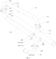
Fig. 1 is a schematic structural diagram of the feeding system according to an embodiment of the present invention; -
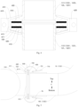
Fig. 2 is a partial schematic structural diagram of the feeding system according to an embodiment of the present invention; -
Fig. 3 is a partial schematic structural diagram of the feeding system according to an embodiment of the present invention; -
Fig. 4 is a partial schematic structural diagram of the feeding system according to an embodiment of the present invention; -
Fig. 5 is a partial schematic structural diagram of the feeding system according to an embodiment of the present invention. - Hereunder some embodiments of the present invention will be detailed, and examples of the embodiments are shown in the accompanying drawings. It should be noted that the embodiments described with reference to the accompanying drawings are only exemplary and are provided only to explain the present invention rather than constituting any limitation to the present invention.
- Hereunder the
feeding system 1 according to an embodiment of the present invention will be described with reference to the accompanying drawings. As shown inFigs. 1-5 , thefeeding system 1 according to an embodiment of the present invention comprises a plurality ofmaterial tanks 20, a plurality ofblowers 30, a dust remover and a connectingpipe 10. - Each
material tank 20 has an air outlet, and the dust remover has an air inlet. The air inlets of the plurality ofblowers 30 are in communication with the air outlets of thematerial tanks 20 in one-to-one correspondence. That is to say, the number of theblowers 30 may be equal to the number of thematerial tanks 20, and the air inlet of eachblower 30 is in communication with the air outlet of onematerial tank 20. - The first end of the connecting
pipe 10 is in communication with the air inlet of the dust remover, and thesecond end 140 of the connectingpipe 10 is movably arranged between a first connection position and a second connection position, wherein, at the first connection position, thesecond end 140 of the connectingpipe 10 is connected with theair outlet 312 of one of the plurality ofblowers 30; at the second connection position, thesecond end 140 of the connectingpipe 10 is connected with theair outlet 312 of another one of the plurality ofblowers 30. In other words, thesecond end 140 of the connectingpipe 10 is switchably connected to any one of the plurality ofblowers 30. - The working process of the
feeding system 1 according to the embodiment of the present invention will be briefly described below with reference toFigs. 1-5 . Before the powdered raw material is loaded into amaterial tank 20, thesecond end 140 of the connectingpipe 10 is connected to theair outlet 312 of theblower 30 in communication with the air outlet of thematerial tank 20 first. When the powdered raw material is loaded into thematerial tank 20, theblower 30 is started to maintain a negative pressure in thematerial tank 20. In view that the air discharged by theblower 30 contains a large amount of dust, it may be discharged through the connectingpipe 10 into the dust remover. - After the powdered raw material is loaded into the
material tank 20, thesecond end 140 of the connectingpipe 10 may be connected to theair outlet 312 of theblower 30 in communication with the air outlet of anothermaterial tank 20 before the powdered raw material is loaded to said anothermaterial tank 20. When the powdered raw material is loaded into said anothermaterial tank 20, theblower 30 is started to maintain a negative pressure in said anothermaterial tank 20. In view that the air discharged by theblower 30 contains a large amount of dust, it may be discharged through the connectingpipe 10 into the dust remover. - That is to say, whenever the powdered raw material is to be loaded into a
material tank 20, thesecond end 140 of the connectingpipe 10 is connected to theair outlet 312 of theblower 30 in communication with the air outlet of thematerial tank 20, so that the dust-containing air discharged by theblower 30 can enter the dust remover through the connectingpipe 10. Thus, the connectingpipe 10 may cooperate with a plurality ofmaterial tanks 20 and a plurality ofblowers 30, so that a plurality ofblowers 30 can share the same connectingpipe 10. - Thus, the structure of the
feeding system 1 can be simplified, i.e., it is unnecessary to provide a separate connectingpipe 10 connected to the dust remover for eachblower 30. Therefore, even if the working space (blending room) of thefeeding system 1 is narrow, theblower 30 that will discharge dust-containing air can be connected with the connectingpipe 10, so as to avoid discharging the dust into the blending room. That is to say, the space occupied by thefeeding system 1 can be reduced. - In the
feeding system 1 according to the embodiment of the present invention, by arranging thesecond end 140 of the connectingpipe 10 movably between the first connection position and the second connection position, a plurality ofblowers 30 can share the connectingpipe 10, so that the dust-containing air discharged by theblowers 30 can enter the dust remover through the connectingpipe 10. - Therefore, the
feeding system 1 according to the embodiment of the present invention has the advantages of simple structure and zero dust leakage, etc. - As shown in
Figs. 1- 5 , in some embodiments of the present invention, thefeeding system 1 comprisesmaterial tanks 20,blowers 30, a connectingpipe 10 and the dust remover. The connectingpipe 10 comprises a first connectingsection 110, atelescopic section 120 and a second connectingsection 130. - The first end of the first connecting
section 110 is in communication with the air inlet of the dust remover. Thetelescopic section 120 is arranged telescopically, and the first end of thetelescopic section 120 is connected with the second end of the first connectingsection 110. Thefirst end 131 of the second connectingsection 130 is connected with thesecond end 125 of thetelescopic section 120, and the second end of the second connectingsection 130 is movably arranged between the first connection position and the second connection position, wherein, at the first connection position, thesecond end 134 of the second connectingsection 130 is connected with theair outlet 312 of one of the plurality ofblowers 30; at the second connection position, thesecond end 134 of the second connectingsection 130 is connected with theair outlet 312 of another one of the plurality ofblowers 30. - Since the connecting
pipe 10 includes thetelescopic section 120, the connectingpipe 10 is also arranged telescopically. Thus, thesecond end 140 of the connectingpipe 10 can be connected more conveniently and easily with theblowers 30 at different distances from the dust remover, so thatmore blowers 30 can share the connectingpipe 10, thereby the structure of thefeeding system 1 is further simplified and the space occupied by thefeeding system 1 is further reduced. - As shown in
Figs. 1 and2 , the first connectingsection 110 may comprise a first connectingsubsection 111 and a second connectingsubsection 112. The first connectingsubsection 111 is arranged vertically, which is to say, the first connectingsubsection 111 may extend in the vertical direction, and the first end of the first connectingsubsection 111 is connected with the air inlet of the dust remover. The second end of the second connectingsubsection 112 is connected with the first end of thetelescopic section 120. - The
first end 1121 of the second connectingsubsection 112 is arranged vertically, which is say, thefirst end 1121 of the second connectingsubsection 112 may extend in the vertical direction. Thefirst end 1121 of the second connectingsubsection 112 is rotatably connected with thesecond end 1111 of the first connectingsubsection 111, and the rotation axis of thefirst end 1121 of the second connectingsubsection 112 extends in the vertical direction. - Thus, the second connecting
subsection 112 can drive thetelescopic section 120 to rotate around the rotation axis of thefirst end 1121 of the second connectingsubsection 112, so as to further expand the scope of movement of thetelescopic section 120 and the connectingpipe 10. Thus, thesecond end 140 of the connectingpipe 10 can be connected more conveniently and easily with theblowers 30 at different distances from the dust remover, so thatmore blowers 30 can share the connectingpipe 10, thereby the structure of thefeeding system 1 is further simplified and the space occupied by thefeeding system 1 is further reduced. - As shown in
Figs. 3 and4 , in an embodiment of the present invention, thefirst end 1121 of the second connectingsubsection 112 is provided with afirst flange 410, thesecond end 1111 of the first connectingsubsection 111 is provided with asecond flange 420, and afirst gasket 510 is arranged between thefirst flange 410 and thesecond flange 420. The connectingpipe 10 further comprises alock cap 60 sleeved on thefirst flange 410 and thesecond flange 420, and asecond gasket 520 is arranged between thelock cap 60 and thefirst flange 410. Thus thelock cap 60 can abut against (press) thesecond flange 420 and thesecond gasket 520, thefirst flange 410 and thesecond flange 420 can abut against thefirst gasket 510, and thefirst flange 410 can also abut against thesecond gasket 520. - The
lock cap 60 comprises afirst sub-cap 610 and asecond sub-cap 620, which are connected with each other by fasteners (not shown in the figures). Thus, the pre-tightening force of thelock cap 60 can be adjusted by the fasteners, so that the friction force between any two of thelock cap 60, thefirst flange 410, thesecond flange 420, thefirst gasket 510 and thesecond gasket 520 that abut against each other can be adjusted. The fasteners may be bolts. - As shown in
Figs. 3 and4 , in a specific example of the present invention, each of thefirst sub-cap 610 and thesecond sub-cap 620 comprises a firstpressing portion 611, a secondpressing portion 612 and a connectingportion 613. The firstpressing portion 611 abuts against (presses) thesecond gasket 520 so as to press thesecond gasket 520 on thefirst flange 410, which is to say, the firstpressing portion 611 and thefirst flange 410 sandwich thesecond gasket 520. The secondpressing portion 612 abuts against thesecond flange 420 so that thefirst flange 410 and thesecond flange 420 sandwich thefirst gasket 510. The connectingportion 613 is connected with each of the firstpressing portion 611 and the secondpressing portion 612, and may be located at the outer side of thefirst flange 410 and thesecond flange 420, which is to say, thefirst flange 410 and thesecond flange 420 are located between the first connectingsubsection 111 and the connectingportion 613 in the radial direction of the first connectingsubsection 111. - The connecting
pipe 10 may further comprise apressing ring 150, the lock cap 60 (the first pressing portion 611) may abut against thepressing ring 150, and thepressing ring 150 may abut against thesecond gasket 520 so as to press thesecond gasket 520 on thefirst flange 410, which is to say, thepressing ring 150 and thefirst flange 410 sandwich thesecond gasket 520. - Preferably the second connecting
subsection 112 is an elbow. More preferably the second connectingsubsection 112 is a 90-degree elbow. - As shown in
Figs. 1 and2 , in an example of the present invention, thetelescopic section 120 comprises afirst subsection 121 and asecond subsection 122. Thefirst subsection 121 is arranged horizontally and thesecond subsection 122 is arranged horizontally, which is to say, both thefirst subsection 121 and thesecond subsection 122 may extend in the horizontal direction. The first end of thefirst subsection 121 is connected with the second end of the first connectingsection 110, and the second end of thesecond subsection 122 is connected with the first end of the second connectingsection 130. The first end of thesecond subsection 122 is rotatably connected with the second end of thefirst subsection 121 with respect to the second end of thefirst subsection 121, and the rotation axis of the first end of thesecond subsection 122 extends in the vertical direction. - Thus at least one of the
first subsection 121 and thesecond subsection 122 can rotate around the rotation axis of the first end of thesecond subsection 122, so that thetelescopic section 120 can be telescoped more easily and conveniently. - As shown in
Figs. 1 and2 , thetelescopic section 120 further comprises a third connectingsubsection 123 and a fourth connectingsubsection 124, wherein the first end of the third connectingsubsection 123 is connected with the second end of thefirst subsection 121, and the second end of the fourth connectingsubsection 124 is connected with the first end of thesecond subsection 122. - The
second end 1231 of the third connectingsubsection 123 is arranged vertically, and thefirst end 1241 of the fourth connectingsubsection 124 is arranged vertically. That is to say, thesecond end 1231 of the third connectingsubsection 123 may extend in the vertical direction, and thefirst end 1241 of the fourth connectingsubsection 124 may extend in the vertical direction. Thefirst end 1241 of the fourth connectingsubsection 124 is rotatably connected with thesecond end 1231 of the third connectingsubsection 123 with respect to thesecond end 1231 of the third connectingsubsection 123, and the rotation axis of thefirst end 1241 of the fourth connectingsubsection 124 extends in the vertical direction. - As shown in
Figs. 3 and4 , thefirst end 1241 of the fourth connectingsubsection 124 is provided with afirst flange 410, thesecond end 1231 of the third connectingsubsection 123 is provided with asecond flange 420, and afirst gasket 510 is arranged between thefirst flange 410 and thesecond flange 420. The connectingpipe 10 further comprises alock cap 60 sleeved on thefirst flange 410 and thesecond flange 420, and asecond gasket 520 is arranged between thelock cap 60 and at least one of thefirst flange 410 and thesecond flange 420. - Thus, the
lock cap 60 can abut against thesecond gasket 520, thefirst flange 410 and thesecond flange 420 can abut against thefirst gasket 510, and thefirst flange 410 can also abut against thesecond gasket 520. In the case that thesecond gasket 520 is not provided between thelock cap 60 and thesecond flange 420, thelock cap 60 can directly abut against thesecond flange 420. - The
lock cap 60 comprises afirst sub-cap 610 and asecond sub-cap 620, which are connected with each other by fasteners (not shown in the figures). Thus, the pre-tightening force of thelock cap 60 can be adjusted by the fasteners, so that the friction force between any two of thelock cap 60, thefirst flange 410, thesecond flange 420, thefirst gasket 510 and thesecond gasket 520 that abut against each other can be adjusted. - As shown in
Figs. 3 and4 , in a specific example of the present invention, each of thefirst sub-cap 610 and thesecond sub-cap 620 comprises a firstpressing portion 611, a secondpressing portion 612 and a connectingportion 613. The firstpressing portion 611 abuts against (presses) thesecond gasket 520 so as to press thesecond gasket 520 on thefirst flange 410, which is to say, the firstpressing portion 611 and thefirst flange 410 sandwich thesecond gasket 520. The secondpressing portion 612 abuts against thesecond flange 420 so that thefirst flange 410 and thesecond flange 420 sandwich thefirst gasket 510. The connectingportion 613 is connected with each of the firstpressing portion 611 and the secondpressing portion 612, and may be located at the outer side thefirst flange 410 and thesecond flange 420, which is to say, thefirst flange 410 and thesecond flange 420 are located between thefirst end 1241 of the fourth connecting subsection 124 (thesecond end 1231 of the third connecting subsection 123) and the connectingportion 613 in the radial direction of thefirst end 1241 of the fourth connecting subsection 124 (the radial direction of thesecond end 1231 of the third connecting subsection 123). - The connecting
pipe 10 may further comprise apressing ring 150, the lock cap 60 (the first pressing portion 611) may abut against thepressing ring 150, and thepressing ring 150 may abut against thesecond gasket 520 so as to press thesecond gasket 520 on thefirst flange 410, which is to say, thepressing ring 150 and thefirst flange 410 sandwich thesecond gasket 520. - Preferably each of the third connecting
subsection 123 and the fourth connectingsubsection 124 is an elbow, more preferably each of the third connectingsubsection 123 and the fourth connectingsubsection 124 is a 90-degree elbow. - In some examples of the present invention, the second connecting
section 130 is arranged rotatably, and the rotation axis of the second connectingsection 130 extends in the horizontal direction. Thus, thesecond end 140 of the connecting pipe 10 (thesecond end 134 of the second connecting section 130) can be moved up and down by rotating the second connectingsection 130 around the rotation axis extending in the horizontal direction, wherein the up-down (vertical) direction is indicated by the arrow A inFigs. 1 and5 . - When the
second end 140 of the connectingpipe 10 moves from the first connection position to the second connection position or from the second connection position to the first connection position, thesecond end 140 of the connectingpipe 10 may be separated from theair outlet 312 of theblower 30 first, and then the second connectingsection 130 may be rotated around the rotation axis extending in the horizontal direction to move thesecond end 140 of the connectingpipe 10 upward. - Next, the
second end 140 of the connectingpipe 10 is moved toward theair outlet 312 of anotherblower 30. When thesecond end 140 of the connectingpipe 10 is adjacent to theair outlet 312 of said anotherblower 30, the second connectingsection 130 may be rotated about a rotation axis extending in the horizontal direction so as to move thesecond end 140 of the connectingpipe 10 downward. Finally, thesecond end 140 of the connectingpipe 10 is connected to theair outlet 312 of said anotherblower 30. - By rotating the second connecting
section 130 around a rotation axis extending in the horizontal direction, it is possible to prevent thematerial tank 20 and theblower 30 from interfering with thesecond end 140 of the connectingpipe 10 when moving thesecond end 140 of the connectingpipe 10, so that thesecond end 140 of the connectingpipe 10 can be moved more conveniently and easily. - Specifically, the
first end 131 of the second connectingsection 130 is rotatably connected with thesecond end 125 of thetelescopic section 120, and the rotation axis of thefirst end 131 of the second connectingsection 130 extends in the horizontal direction. Thus, the structure of the connectingpipe 10 and thefeeding system 1 is more reasonable. - As shown in
Figs. 1 and2 , the second connectingsection 130 comprises a fifth connectingsubsection 132 and a sixth connectingsubsection 133, wherein thefirst end 1321 of the fifth connectingsubsection 132 is connected with thesecond end 125 of thetelescopic section 120, and thesecond end 1332 of the sixth connectingsubsection 133 is movably arranged between the first connection position and the second connection position. At the first connection position, thesecond end 1332 of the sixth connectingsubsection 133 is connected with theair outlet 312 of one of the plurality ofblowers 30; at the second connection position, thesecond end 1332 of the sixth connectingsubsection 133 is connected with theair outlet 312 of another one of the plurality ofblowers 30. - The
second end 1322 of the fifth connectingsubsection 132 is arranged vertically, and thefirst end 1331 of the sixth connectingsubsection 133 is arranged vertically, which is to say, thesecond end 1322 of the fifth connectingsubsection 132 may extend in the vertical direction, and thefirst end 1331 of the sixth connectingsubsection 133 may extend in the vertical direction. Thefirst end 1331 of the sixth connectingsubsection 133 is rotatably connected with thesecond end 1322 of the fifth connectingsubsection 132, and the rotation axis of thefirst end 1331 of the sixth connectingsubsection 133 extends in the vertical direction. - When the
second end 1332 of the sixth connectingsubsection 133 moves from the first connection position to the second connection position or from the second connection position to the first connection position, thesecond end 1332 of the sixth connectingsubsection 133 may be separated from theair outlet 312 of theblower 30 first, and then thesecond end 1332 of the sixth connectingsubsection 133 may be rotated around a rotating axis extending in the vertical direction, so as to prevent thesecond end 1332 of the sixth connectingsubsection 133 from colliding with theblower 30 when the second connectingsection 130 is rotated. - When the
second end 1332 of the sixth connectingsubsection 133 is adjacent to theair outlet 312 of anotherblower 30, the second connectingsection 130 may be rotated first so that thesecond end 140 of the connectingpipe 10 moves downward, and then thesecond end 1332 of the sixth connectingsubsection 133 may be rotated around a rotation axis extending in the vertical direction so as to accurately adjust the position of thesecond end 1332 of the sixth connectingsubsection 133, thus thesecond end 1332 of the sixth connectingsubsection 133 can be connected to theair outlet 312 of said anotherblower 30 more conveniently and easily. - As shown in
Figs. 3 and4 , thefirst end 1331 of the sixth connectingsubsection 133 is provided with afirst flange 410, thesecond end 1322 of the fifth connectingsubsection 132 is provided with asecond flange 420, and afirst gasket 510 is arranged between thefirst flange 410 and thesecond flange 420. The connectingpipe 10 further comprises alock cap 60 sleeved on thefirst flange 410 and thesecond flange 420, and asecond gasket 520 is arranged between thelock cap 60 and thefirst flange 410. Thus, thelock cap 60 can abut against (press) thesecond flange 420 and thesecond gasket 520, thefirst flange 410 and thesecond flange 420 can abut against thefirst gasket 510, and thefirst flange 410 can also abut against thesecond gasket 520. - The
lock cap 60 comprises afirst sub-cap 610 and asecond sub-cap 620, which are connected with each other by fasteners (not shown in the figures). Thus, the pre-tightening force of thelock cap 60 can be adjusted by the fasteners, so that the friction force between any two of thelock cap 60, thefirst flange 410, thesecond flange 420, thefirst gasket 510 and thesecond gasket 520 that abut against each other can be adjusted. - As shown in
Figs. 3 and4 , in a specific example of the present invention, each of thefirst sub-cap 610 and thesecond sub-cap 620 comprises a firstpressing portion 611, a secondpressing portion 612 and a connectingportion 613. The firstpressing portion 611 abuts against (presses) thesecond gasket 520 so as to press thesecond gasket 520 on thefirst flange 410, which is to say, the firstpressing portion 611 and thefirst flange 410 sandwich thesecond gasket 520. The secondpressing portion 612 abuts against thesecond flange 420 so that thefirst flange 410 and thesecond flange 420 sandwich thefirst gasket 510. The connectingportion 613 is connected with each of the firstpressing portion 611 and the secondpressing portion 612, and may be located at the outer side thefirst flange 410 and thesecond flange 420, which is to say, thefirst flange 410 and thesecond flange 420 are located between thefirst end 1331 of the sixth connecting subsection 133 (thesecond end 1322 of the fifth connecting subsection 132) and the connectingportion 613 in the radial direction of thefirst end 1331 of the sixth connecting subsection 133 (the radial direction of thesecond end 1322 of the fifth connecting subsection 132). - The connecting
pipe 10 may further comprise apressing ring 150, the lock cap 60 (the first pressing portion 611) may abut against thepressing ring 150, and thepressing ring 150 may abut against thesecond gasket 520 so as to press thesecond gasket 520 on thefirst flange 410, which is to say, thepressing ring 150 and thefirst flange 410 sandwich thesecond gasket 520. - Preferably each of the fifth connecting
subsection 132 and the sixth connectingsubsection 133 is an elbow. More preferably each of the fifth connectingsubsection 132 and the sixth connectingsubsection 133 is a 90-degree elbow. - As shown in
Figs. 3 and4 , thefirst end 131 of the second connecting section 130 (thefirst end 1321 of the fifth connecting subsection 132) is provided with afirst flange 410, thesecond end 125 of the telescopic section 120 (thesecond end 1221 of the second subsection 122) is provided with asecond flange 420, and afirst gasket 510 is arranged between thefirst flange 410 and thesecond flange 420. The connectingpipe 10 further comprises alock cap 60 sleeved on thefirst flange 410 and thesecond flange 420, and asecond gasket 520 is arranged between thelock cap 60 and thefirst flange 410. Thus, thelock cap 60 can abut against (press) thesecond flange 420 and thesecond gasket 520, thefirst flange 410 and thesecond flange 420 can abut against thefirst gasket 510, and thefirst flange 410 can also abut against thesecond gasket 520. - The
lock cap 60 comprises afirst sub-cap 610 and asecond sub-cap 620, which are connected with each other by fasteners (not shown in the figures). Thus, the pre-tightening force of thelock cap 60 can be adjusted by the fasteners, so that the friction force between any two of thelock cap 60, thefirst flange 410, thesecond flange 420, thefirst gasket 510 and thesecond gasket 520 that abut against each other can be adjusted. - As shown in
Figs. 3 and4 , in a specific example of the present invention, each of thefirst sub-cap 610 and thesecond sub-cap 620 comprises a firstpressing portion 611, a secondpressing portion 612 and a connectingportion 613. The firstpressing portion 611 abuts against (presses) thesecond gasket 520 so as to press thesecond gasket 520 on thefirst flange 410, which is to say, the firstpressing portion 611 and thefirst flange 410 sandwich thesecond gasket 520. The secondpressing portion 612 abuts against thesecond flange 420 so that thefirst flange 410 and thesecond flange 420 sandwich thefirst gasket 510. The connectingportion 613 is connected with each of the firstpressing portion 611 and the secondpressing portion 612, and may be located at the outer side thefirst flange 410 and thesecond flange 420, which is to say, thefirst flange 410 and thesecond flange 420 are located between thefirst end 131 of the second connecting section 130 (thesecond end 125 of the telescopic section 120) and the connectingportion 613 in the radial direction of thefirst end 131 of the second connecting section 130 (the radial direction of thesecond end 125 of the telescopic section 120). - The connecting
pipe 10 may further comprise apressing ring 150, the lock cap 60 (the first pressing portion 611) may abut against thepressing ring 150, and thepressing ring 150 may abut against thesecond gasket 520 so as to press thesecond gasket 520 on thefirst flange 410, which is to say, thepressing ring 150 and thefirst flange 410 sandwich thesecond gasket 520. - As shown in
Figs. 1 and5 , thesecond end 140 of the connecting pipe 10 (thesecond end 1332 of the sixth connecting subsection 133) is arranged horizontally, and thevolute casing 310 of eachblower 30 has anair discharge portion 311 arranged horizontally, which is to say, thesecond end 140 of the connectingpipe 10 may extend in the horizontal direction, and theair discharge portion 311 may extend in the horizontal direction. Thefree end 3111 of theair discharge portion 311 defines theair outlet 312 of theblower 30. At the first connection position, thesecond end 140 of the connectingpipe 10 is connected with thefree end 3111 of one of the plurality ofblowers 30; at the second connection position, thesecond end 140 of the connectingpipe 10 is connected with thefree end 3111 of another one of the plurality ofblowers 30. - As shown in
Figs. 1 and5 , thesecond end 140 of the connectingpipe 10 is provided with athird flange 430, and theair discharge portion 311 is provided with afourth flange 440. The connectingpipe 10 further comprises a connectingshackle 70, which comprises a manipulatingportion 710 and ahook portion 720. The manipulatingportion 710 is hinged to thesecond end 140 of the connectingpipe 10, and thefirst end 721 of thehook portion 720 is connected with the manipulatingportion 710. - When the
second end 140 of the connectingpipe 10 is at the first connection position or the second connection position, thethird flange 430 is fitted with thefourth flange 440 on the corresponding blower 30 (directly contact or indirect contact via the third gasket 530), and thesecond end 722 of thehook portion 720 hooks thefourth flange 440, so as to press thefourth flange 440 on thethird flange 430. - A plurality of connecting
shackles 70 may be provided, and the plurality of connectingshackles 70 may be arranged at an interval in the circumferential direction of thesecond end 140 of the connectingpipe 10. Next, the technical scheme of the present application will be further described in an example of an upper connectingshackle 70 inFig. 5 . - The lower end of the manipulating
portion 710 may be hinged to thesecond end 140 of the connectingpipe 10. When the manipulatingportion 710 rotates clockwise, thesecond end 722 of thehook portion 720 moves toward thethird flange 430, so as to press thefourth flange 440 on thethird flange 430. When the manipulatingportion 710 rotates counterclockwise, thesecond end 722 of thehook portion 720 moves away from thethird flange 430, so that thethird flange 430 can be separated from thefourth flange 440. - The
third gasket 530 between thethird flange 430 and thefourth flange 440 may be made of rubber, so that thethird flange 430 and thefourth flange 440 can be connected together more tightly, and thus leakage of dust-containing gas between thethird flange 430 and thefourth flange 440 can be prevented. - As shown in
Fig. 2 , thefeeding system 1 may further comprises a first supportingframe 810 and a second supportingframe 820. The connectingpipe 10 may be retracted when no powdered raw material is loaded into thematerial tanks 20. Thefirst subsection 121 may be supported on the first supportingframe 810, and thesecond subsection 122 may be supported on the second supportingframe 820. - The present invention further provides a glass production apparatus. The glass production apparatus according to an embodiment of the present invention comprises a kiln (not shown in the figures), a mixing
tank 20, and thefeeding system 1 according to the above embodiment of the present invention. The feed inlet of the mixingtank 20 is in communication with the discharge outlet of eachtank 20 of thefeeding system 1, and the feed inlet of the kiln is in communication with the discharge outlet of the mixingtank 20. - Therefore, the glass production apparatus according to the embodiment of the present invention has the advantages of simple structure and zero dust leakage.
- In the description of the present invention, it should be understood that the orientation or position relations indicated by terms "above", "below", "vertical", "horizontal", "top", "bottom", "clockwise", "radial", or "circumferential", are based on the orientation or position relations indicated in the accompanying drawings. They are used only to ease and simplify the description of the present invention, rather than indicating or implying that the involved device or component must have a specific orientation or must be constructed and operated in a specific orientation.
- In addition, the terms "first" and "second" are used only for description purpose, and shall not be interpreted as indicating or implying relative importance or implicitly indicating the quantity of the indicated technical feature. Hence, a feature confined by "first" or "second" may explicitly or implicitly comprise at least one such feature. In the description of the present invention, "a plurality of' or "multiple" means at least two, such as two or more, unless otherwise specified explicitly.
- In the present invention, unless otherwise specified and defined explicitly, the terms "install", "link", "connect", "fix", shall be interpreted in their general meaning. For example, the connection may be fixed connection, detachable connection, or integral connection; may be mechanical connection or electrical connection or in communication with each other; may be direct connection or indirect connection via an intermediate medium, or internal communication or interactive relation between two elements unless otherwise defined explicitly. Those having ordinary skills in the art may interpret the specific meanings of the terms in the present invention in their context.
- In the present invention, unless otherwise specified and defined explicitly, a first feature "above" or "below" a second feature may represent that the first feature and the second feature directly contact with each other or the first feature and the second feature contact with each other indirectly via an intermediate medium. In addition, a first feature "above" or "over" a second feature may represent that the first feature is right above or diagonally above the second feature, or may only represent that the elevation of the first feature is higher than that of the second feature. A first feature being "below" or "under" a second feature may represent that the first feature is right below or diagonally below the second feature, or may only represent that the elevation of the first feature is lower than that of the second feature.
- In the description of the present invention, the expressions of reference terms "an embodiment", "some embodiments", "an example", "a specific example", or "some examples" mean that the specific features, structures, materials or characteristics described in those embodiments or examples are included in at least one embodiment or example of the present invention. In this document, the exemplary expression of the above terms may not necessarily refer to the same embodiment or example.
Claims (15)
- A feeding system (1), comprising:a plurality of material tanks (20), each of which has an air outlet;a plurality of blowers (30), having air inlets in communication with air outlets of the material tanks (20) in one-to-one correspondence;a dust remover, having an air inlet; anda connecting pipe (10), having a first end in communication with the air inlet of the dust remover and a second end movably arranged between a first connection position and a second connection position, wherein, at the first connection position, the second end is connected with the air outlet (312) of one of the plurality of blowers (30); at the second connection position, the second end is connected with the air outlet (312) of another one of the plurality of blowers (30).
- The feeding system (1) according to claim 1, wherein the connecting pipe (10) comprises:a first connecting section (110), having a first end in communication with the air inlet of the dust remover;a telescopic section (120) arranged telescopically, having a first end connected with a second end of the first connecting section (110); anda second connecting section (130), having a first end connected with a second end of the telescopic section (120) and a second end movably arranged between the first connection position and the second connection position, wherein, at the first connection position, the second end of the second connecting section (130) is connected with the air outlet (312) of one of the plurality of blowers (30); at the second connection position, the second end of the second connecting section (130) is connected with the air outlet (312) of another one of the plurality of blowers (30).
- The feeding system (1) according to claim 2, wherein the first connecting section (110) comprises:a first connecting subsection (111) arranged vertically, having a first end connected with the air inlet of the dust remover; anda second connecting subsection (112), having a second end connected with the first end of the telescopic section (120) and a first end vertically arranged and rotatably connected with the second end of the first connecting subsection (111), wherein the rotation axis of the first end of the second connecting subsection (112) extends in the vertical direction.
- The feeding system (1) according to claim 2, wherein the telescopic section (120) comprises:a first subsection (121) arranged horizontally, having a first end connected with the second end of the first connecting section (110); anda second subsection (122) arranged horizontally, having a second end connected with the first end of the second connecting section (130) and a first end rotatably connected with the second end of the first subsection (121) with respect to the second end of the first subsection (121), wherein the rotation axis of the first end of the second subsection (122) extends in the vertical direction;preferably, wherein the telescopic section (120) further comprises a third connecting subsection (123) having a first end connected with the second end of the first subsection (121) and a second end vertically arranged; and a fourth connecting subsection (124) having a first end vertically arranged and rotatably connected with the second end of the third connecting subsection (123) with respect to the second end of the third connecting subsection (123) and a second end connected with the first end of the second connecting subsection (122), wherein the rotation axis of the first end of the fourth connecting subsection (124) extends in the vertical direction.
- The feeding system (1) according to claim 2, wherein the second connecting section (130) is rotatably arranged, and the rotation axis of the second connecting section (130) extends in the horizontal direction;
preferably, wherein the second connecting section (130) comprises a fifth connecting subsection (132) having a first end connected with the second end of the telescopic section (120) and a second end arranged vertically; and a sixth connecting subsection (133) having a first end vertically arranged and rotatably connected with the second end of the fifth connecting subsection (132) and a second end movably arranged between the first connection position and the second connection position, wherein the rotation axis of the first end of the sixth connecting subsection (133) extends in the vertical direction. - The feeding system (1) according to claim 1, wherein the second end of the connecting pipe (10) is arranged horizontally, and a volute casing (310) of each of the plurality of blowers (30) has an air discharge portion (311) arranged horizontally, which has a free end (3111) defining the air outlet (312) of the blower (30), wherein, at the first connection position, the second end is connected with the free end (3111) of one of the plurality of blowers (30); at the second connection position, the second end is connected with the free end (3111) of another one of the plurality of blowers (30);
preferably, wherein the second end of the connecting pipe (10) is provided with a third flange (430), the air discharge portion (311) is provided with a fourth flange (440), and the connecting pipe (10) further comprises a connecting shackle (70), which comprises:a manipulating portion (710) hinged to the second end of the connecting pipe (10); anda hook portion (720) having a first end connected with the manipulating portion (710), wherein, when the second end of the connecting pipe (10) is at the first connection position or the second connection position, the third flange (430) is fitted with the fourth flange (440) on the corresponding blower (30), and the second end of the hook portion (720) hooks the fourth flange (440), so as to press the fourth flange (440) on the third flange (430). - The feeding system (1) according to claim 3, wherein the second connecting subsection (112) is an elbow,
preferably, wherein the first end of the second connecting subsection (112) is provided with a first flange (410), the second end of the first connecting subsection (111) is provided with a second flange (420), a first gasket (510) is provided between the first flange (410) and the second flange (420), the connecting pipe (10) further comprises a lock cap (60) sleeved on the first flange (410) and the second flange (420), and a second gasket (520) is provided between the lock cap (60) and the first flange (410), wherein the lock cap (60) comprises a first sub-cap (610) and a second sub-cap (620), which are connected with each other by fasteners. - The feeding system (1) according to claim 4, wherein each of the third connecting subsection (123) and the fourth connecting subsection (124) is an elbow, preferably each of the third connecting subsection (123) and the fourth connecting subsection (124) is a 90-degree elbow.
- The feeding system (1) according to claim 4, wherein the first end of the fourth connecting subsection (124) is provided with a first flange (410), the second end of the third connecting subsection (123) is provided with a second flange (420), a first gasket (510) is provided between the first flange (410) and the second flange (420), the connecting pipe (10) further comprises a lock cap (60) sleeved on the first flange (410) and the second flange (420), and a second gasket (520) is provided between the lock cap (60) and at least one of the first flange (410) and the second flange (420), wherein the lock cap (60) comprises a first sub-cap (610) and a second sub-cap (620), which are connected with each other by fasteners.
- The feeding system (1) according to claim 5, wherein the first end of the second connecting section (130) is rotatably connected with the second end of the telescopic section (120), and the rotation axis of the first end of the second connecting section (130) extends in the horizontal direction.
- The feeding system (1) according to claim 5, wherein the first end of the second connecting section (130) is provided with a first flange (410), the second end of the telescopic section (120) is provided with a second flange (420), a first gasket (510) is provided between the first flange (410) and the second flange (420), the connecting pipe (10) further comprises a lock cap (60) sleeved on the first flange (410) and the second flange (420), and a second gasket (520) is provided between the lock cap (60) and the first flange (410), wherein the lock cap (60) comprises a first sub-cap (610) and a second sub-cap (620), which are connected with each other by fasteners.
- The feeding system (1) according to claim 5, wherein each of the fifth connecting subsection (132) and the sixth connecting subsection (133) is an elbow, preferably each of the fifth connecting subsection (132) and the sixth connecting subsection (133) is a 90-degree elbow.
- The feeding system (1) according to claim 5, wherein the first end of the sixth connecting subsection (133) is provided with a first flange (410), the second end of the fifth connecting subsection (132) is provided with a second flange (420), a first gasket (510) is provided between the first flange (410) and the second flange (420), the connecting pipe (10) further comprises a lock cap (60) sleeved on the first flange (410) and the second flange (420), and a second gasket (520) is provided between the lock cap (60) and the first flange (410), wherein the lock cap (60) comprises a first sub-cap (610) and a second sub-cap (620), which are connected with each other by fasteners.
- The feeding system (1) according to claim 7, wherein the second connecting subsection (112) is a 90-degree elbow.
- A glass production apparatus, comprising:the feeding system (1) according to any of claims 1-14;a mixing tank (20), having a feed inlet in communication with a discharge outlet of each of the material tanks (20) of the feeding system (1); anda kiln, having a feed inlet in communication with a discharge outlet of the mixing tank (20).
Applications Claiming Priority (2)
| Application Number | Priority Date | Filing Date | Title |
|---|---|---|---|
| CN201910228876.4A CN109966985B (en) | 2019-03-25 | 2019-03-25 | Feeding system and glass production equipment with same |
| PCT/CN2019/087240 WO2020191898A1 (en) | 2019-03-25 | 2019-05-16 | Feeding system, and glass production apparatus having same |
Publications (3)
| Publication Number | Publication Date |
|---|---|
| EP3950607A1 EP3950607A1 (en) | 2022-02-09 |
| EP3950607A4 EP3950607A4 (en) | 2022-05-04 |
| EP3950607B1 true EP3950607B1 (en) | 2023-04-26 |
Family
ID=67080430
Family Applications (1)
| Application Number | Title | Priority Date | Filing Date |
|---|---|---|---|
| EP19921915.5A Active EP3950607B1 (en) | 2019-03-25 | 2019-05-16 | Feeding system, and glass production apparatus having same |
Country Status (6)
| Country | Link |
|---|---|
| US (1) | US12024460B2 (en) |
| EP (1) | EP3950607B1 (en) |
| JP (1) | JP7293396B2 (en) |
| KR (1) | KR102654489B1 (en) |
| CN (1) | CN109966985B (en) |
| WO (1) | WO2020191898A1 (en) |
Families Citing this family (1)
| Publication number | Priority date | Publication date | Assignee | Title |
|---|---|---|---|---|
| CN113511797B (en) * | 2021-05-27 | 2023-03-28 | 陕西雷博创新光电科技有限公司 | Automatic feeding process and device for optical glass production line |
Family Cites Families (17)
| Publication number | Priority date | Publication date | Assignee | Title |
|---|---|---|---|---|
| DE1965169A1 (en) | 1969-01-30 | 1970-08-13 | Starkstrom Anlagenbau Veb K | Method and circuit arrangement for chain dimension processing, preferably in machine tool controls with an absolute position measuring system |
| US3794475A (en) * | 1973-04-18 | 1974-02-26 | Philadelphia Quartz Co | Method of preparing soluble silicate flakes or fibers |
| JPH08285990A (en) | 1995-04-13 | 1996-11-01 | Ishikawajima Harima Heavy Ind Co Ltd | Heated object supply device in glass melting furnace |
| DE19651691C2 (en) * | 1996-01-25 | 1998-07-02 | Sorg Gmbh & Co Kg | Method and device for melting glass with simultaneous exhaust gas purification |
| JPH11128780A (en) * | 1997-10-24 | 1999-05-18 | Namihito Gotou | Mechanism for removing pollutant contained in exhaust with water as medium |
| KR20010056265A (en) | 1999-12-14 | 2001-07-04 | 서두칠 | Ventilator for feeder |
| JP2005154165A (en) | 2003-11-21 | 2005-06-16 | Nippon Electric Glass Co Ltd | Tank furnace for melting glass and method of melting glass |
| CN101333061B (en) | 2008-08-05 | 2010-09-29 | 河南安飞电子玻璃有限公司 | Conveying process for liquid crystal glass primary materials |
| CN202912190U (en) * | 2012-10-11 | 2013-05-01 | 安徽嘉新特种工程材料有限责任公司 | Dust collecting and pressure reducing device of slurry blending cementing tank |
| CN203682018U (en) * | 2014-01-03 | 2014-07-02 | 佛山市金银河智能装备股份有限公司 | Continuous powder conveying device with drying function |
| WO2016076883A1 (en) * | 2014-11-14 | 2016-05-19 | Halliburton Energy Services, Inc. | Dust control in pneumatic particulate handling applications |
| JP5880750B2 (en) | 2015-03-03 | 2016-03-09 | 日本電気硝子株式会社 | Raw material powder blender |
| CN205109265U (en) | 2015-11-13 | 2016-03-30 | 大连海鑫化工有限公司 | Shaping granulation equipment with from dust pelletizing system |
| CN205347187U (en) | 2016-01-14 | 2016-06-29 | 秦皇岛班驰输送技术有限公司 | A integrated feed proportioning system for glass production line |
| CN206735278U (en) * | 2017-01-24 | 2017-12-12 | 福建省三明正元化工有限公司 | A kind of waterglass raw materials for production automatic feed mixing arrangement |
| CN108274616A (en) | 2017-12-27 | 2018-07-13 | 中核四0四有限公司 | A kind of device of flyash and cement mixture |
| CN108714397A (en) * | 2018-07-13 | 2018-10-30 | 湖南麦克斯搅拌捏合设备有限公司 | A kind of portable powder feed system |
-
2019
- 2019-03-25 CN CN201910228876.4A patent/CN109966985B/en active Active
- 2019-05-16 WO PCT/CN2019/087240 patent/WO2020191898A1/en not_active Ceased
- 2019-05-16 KR KR1020217034459A patent/KR102654489B1/en active Active
- 2019-05-16 US US17/442,472 patent/US12024460B2/en active Active
- 2019-05-16 JP JP2021560133A patent/JP7293396B2/en active Active
- 2019-05-16 EP EP19921915.5A patent/EP3950607B1/en active Active
Also Published As
| Publication number | Publication date |
|---|---|
| KR102654489B1 (en) | 2024-04-04 |
| EP3950607A1 (en) | 2022-02-09 |
| JP7293396B2 (en) | 2023-06-19 |
| KR20210152489A (en) | 2021-12-15 |
| CN109966985A (en) | 2019-07-05 |
| CN109966985B (en) | 2020-01-31 |
| EP3950607A4 (en) | 2022-05-04 |
| US20220162109A1 (en) | 2022-05-26 |
| WO2020191898A1 (en) | 2020-10-01 |
| US12024460B2 (en) | 2024-07-02 |
| JP2022528735A (en) | 2022-06-15 |
Similar Documents
| Publication | Publication Date | Title |
|---|---|---|
| CN103920446A (en) | Integrated spherical multifunctional machine | |
| US12024460B2 (en) | Feeding system and glass production apparatus having same | |
| CN209464923U (en) | A kind of novel material mixing arrangement | |
| CN219849278U (en) | Combined type premixing machine | |
| CN117963504A (en) | Screw feeding conveyor | |
| CN209476078U (en) | A kind of dye stirring device of uniform feeding | |
| CN208098015U (en) | A kind of top drive formula wet mixing pelletizer | |
| CN216878882U (en) | Dosing unit is used in special refractory material production and processing | |
| CN205932463U (en) | Cement powder conveyor | |
| CN204736361U (en) | EPS walling production facility | |
| CN210058141U (en) | Mixture distributing device | |
| CN104842468B (en) | A kind of EPS wallings production equipment and production method | |
| CN210368523U (en) | A kind of quick disassembly type asphalt mixture mixing equipment | |
| CN105854679A (en) | Vertical dry powder stirring machine for valve powder paint production | |
| CN208394393U (en) | A kind of feed bin with sub-material spiral | |
| CN218131620U (en) | An automatic proportioning device for raw materials used in the production of charge | |
| CN117258631B (en) | Combined type premixing machine | |
| CN219091970U (en) | Movable solid feeding device | |
| CN219688727U (en) | Storage device of multistage pay-off | |
| CN207941479U (en) | A kind of coating material production mixing arrangement | |
| CN223697612U (en) | Weighing and mixing device | |
| CN206391964U (en) | A kind of Novel blending machine | |
| CN213942977U (en) | Spherical mixing mechanism | |
| CN219522749U (en) | Pellet mixture feeder hopper | |
| CN215754274U (en) | High-viscosity easy-arching flat-bottom bin discharging device |
Legal Events
| Date | Code | Title | Description |
|---|---|---|---|
| STAA | Information on the status of an ep patent application or granted ep patent |
Free format text: STATUS: THE INTERNATIONAL PUBLICATION HAS BEEN MADE |
|
| PUAI | Public reference made under article 153(3) epc to a published international application that has entered the european phase |
Free format text: ORIGINAL CODE: 0009012 |
|
| STAA | Information on the status of an ep patent application or granted ep patent |
Free format text: STATUS: REQUEST FOR EXAMINATION WAS MADE |
|
| 17P | Request for examination filed |
Effective date: 20211018 |
|
| AK | Designated contracting states |
Kind code of ref document: A1 Designated state(s): AL AT BE BG CH CY CZ DE DK EE ES FI FR GB GR HR HU IE IS IT LI LT LU LV MC MK MT NL NO PL PT RO RS SE SI SK SM TR |
|
| A4 | Supplementary search report drawn up and despatched |
Effective date: 20220407 |
|
| RIC1 | Information provided on ipc code assigned before grant |
Ipc: F23J 15/02 20060101ALI20220401BHEP Ipc: C03B 1/00 20060101ALI20220401BHEP Ipc: B08B 15/00 20060101AFI20220401BHEP |
|
| DAV | Request for validation of the european patent (deleted) | ||
| DAX | Request for extension of the european patent (deleted) | ||
| REG | Reference to a national code |
Ref country code: DE Ref legal event code: R079 Ref document number: 602019028207 Country of ref document: DE Free format text: PREVIOUS MAIN CLASS: C03B0003000000 Ipc: B08B0015000000 |
|
| GRAP | Despatch of communication of intention to grant a patent |
Free format text: ORIGINAL CODE: EPIDOSNIGR1 |
|
| STAA | Information on the status of an ep patent application or granted ep patent |
Free format text: STATUS: GRANT OF PATENT IS INTENDED |
|
| RIC1 | Information provided on ipc code assigned before grant |
Ipc: F23J 15/02 20060101ALI20221115BHEP Ipc: C03B 1/00 20060101ALI20221115BHEP Ipc: B08B 15/00 20060101AFI20221115BHEP |
|
| INTG | Intention to grant announced |
Effective date: 20221201 |
|
| GRAS | Grant fee paid |
Free format text: ORIGINAL CODE: EPIDOSNIGR3 |
|
| GRAA | (expected) grant |
Free format text: ORIGINAL CODE: 0009210 |
|
| STAA | Information on the status of an ep patent application or granted ep patent |
Free format text: STATUS: THE PATENT HAS BEEN GRANTED |
|
| AK | Designated contracting states |
Kind code of ref document: B1 Designated state(s): AL AT BE BG CH CY CZ DE DK EE ES FI FR GB GR HR HU IE IS IT LI LT LU LV MC MK MT NL NO PL PT RO RS SE SI SK SM TR |
|
| REG | Reference to a national code |
Ref country code: GB Ref legal event code: FG4D |
|
| REG | Reference to a national code |
Ref country code: CH Ref legal event code: EP |
|
| REG | Reference to a national code |
Ref country code: DE Ref legal event code: R096 Ref document number: 602019028207 Country of ref document: DE |
|
| REG | Reference to a national code |
Ref country code: AT Ref legal event code: REF Ref document number: 1562466 Country of ref document: AT Kind code of ref document: T Effective date: 20230515 |
|
| REG | Reference to a national code |
Ref country code: IE Ref legal event code: FG4D |
|
| REG | Reference to a national code |
Ref country code: LT Ref legal event code: MG9D |
|
| REG | Reference to a national code |
Ref country code: NL Ref legal event code: MP Effective date: 20230426 |
|
| REG | Reference to a national code |
Ref country code: AT Ref legal event code: MK05 Ref document number: 1562466 Country of ref document: AT Kind code of ref document: T Effective date: 20230426 |
|
| PG25 | Lapsed in a contracting state [announced via postgrant information from national office to epo] |
Ref country code: NL Free format text: LAPSE BECAUSE OF FAILURE TO SUBMIT A TRANSLATION OF THE DESCRIPTION OR TO PAY THE FEE WITHIN THE PRESCRIBED TIME-LIMIT Effective date: 20230426 |
|
| PG25 | Lapsed in a contracting state [announced via postgrant information from national office to epo] |
Ref country code: SE Free format text: LAPSE BECAUSE OF FAILURE TO SUBMIT A TRANSLATION OF THE DESCRIPTION OR TO PAY THE FEE WITHIN THE PRESCRIBED TIME-LIMIT Effective date: 20230426 Ref country code: PT Free format text: LAPSE BECAUSE OF FAILURE TO SUBMIT A TRANSLATION OF THE DESCRIPTION OR TO PAY THE FEE WITHIN THE PRESCRIBED TIME-LIMIT Effective date: 20230828 Ref country code: NO Free format text: LAPSE BECAUSE OF FAILURE TO SUBMIT A TRANSLATION OF THE DESCRIPTION OR TO PAY THE FEE WITHIN THE PRESCRIBED TIME-LIMIT Effective date: 20230726 Ref country code: ES Free format text: LAPSE BECAUSE OF FAILURE TO SUBMIT A TRANSLATION OF THE DESCRIPTION OR TO PAY THE FEE WITHIN THE PRESCRIBED TIME-LIMIT Effective date: 20230426 Ref country code: AT Free format text: LAPSE BECAUSE OF FAILURE TO SUBMIT A TRANSLATION OF THE DESCRIPTION OR TO PAY THE FEE WITHIN THE PRESCRIBED TIME-LIMIT Effective date: 20230426 |
|
| PG25 | Lapsed in a contracting state [announced via postgrant information from national office to epo] |
Ref country code: RS Free format text: LAPSE BECAUSE OF FAILURE TO SUBMIT A TRANSLATION OF THE DESCRIPTION OR TO PAY THE FEE WITHIN THE PRESCRIBED TIME-LIMIT Effective date: 20230426 Ref country code: PL Free format text: LAPSE BECAUSE OF FAILURE TO SUBMIT A TRANSLATION OF THE DESCRIPTION OR TO PAY THE FEE WITHIN THE PRESCRIBED TIME-LIMIT Effective date: 20230426 Ref country code: LV Free format text: LAPSE BECAUSE OF FAILURE TO SUBMIT A TRANSLATION OF THE DESCRIPTION OR TO PAY THE FEE WITHIN THE PRESCRIBED TIME-LIMIT Effective date: 20230426 Ref country code: LT Free format text: LAPSE BECAUSE OF FAILURE TO SUBMIT A TRANSLATION OF THE DESCRIPTION OR TO PAY THE FEE WITHIN THE PRESCRIBED TIME-LIMIT Effective date: 20230426 Ref country code: IS Free format text: LAPSE BECAUSE OF FAILURE TO SUBMIT A TRANSLATION OF THE DESCRIPTION OR TO PAY THE FEE WITHIN THE PRESCRIBED TIME-LIMIT Effective date: 20230826 Ref country code: HR Free format text: LAPSE BECAUSE OF FAILURE TO SUBMIT A TRANSLATION OF THE DESCRIPTION OR TO PAY THE FEE WITHIN THE PRESCRIBED TIME-LIMIT Effective date: 20230426 Ref country code: GR Free format text: LAPSE BECAUSE OF FAILURE TO SUBMIT A TRANSLATION OF THE DESCRIPTION OR TO PAY THE FEE WITHIN THE PRESCRIBED TIME-LIMIT Effective date: 20230727 |
|
| PG25 | Lapsed in a contracting state [announced via postgrant information from national office to epo] |
Ref country code: FI Free format text: LAPSE BECAUSE OF FAILURE TO SUBMIT A TRANSLATION OF THE DESCRIPTION OR TO PAY THE FEE WITHIN THE PRESCRIBED TIME-LIMIT Effective date: 20230426 |
|
| PG25 | Lapsed in a contracting state [announced via postgrant information from national office to epo] |
Ref country code: SK Free format text: LAPSE BECAUSE OF FAILURE TO SUBMIT A TRANSLATION OF THE DESCRIPTION OR TO PAY THE FEE WITHIN THE PRESCRIBED TIME-LIMIT Effective date: 20230426 |
|
| PG25 | Lapsed in a contracting state [announced via postgrant information from national office to epo] |
Ref country code: MC Free format text: LAPSE BECAUSE OF FAILURE TO SUBMIT A TRANSLATION OF THE DESCRIPTION OR TO PAY THE FEE WITHIN THE PRESCRIBED TIME-LIMIT Effective date: 20230426 |
|
| REG | Reference to a national code |
Ref country code: DE Ref legal event code: R097 Ref document number: 602019028207 Country of ref document: DE |
|
| REG | Reference to a national code |
Ref country code: BE Ref legal event code: MM Effective date: 20230531 |
|
| PG25 | Lapsed in a contracting state [announced via postgrant information from national office to epo] |
Ref country code: SM Free format text: LAPSE BECAUSE OF FAILURE TO SUBMIT A TRANSLATION OF THE DESCRIPTION OR TO PAY THE FEE WITHIN THE PRESCRIBED TIME-LIMIT Effective date: 20230426 Ref country code: SK Free format text: LAPSE BECAUSE OF FAILURE TO SUBMIT A TRANSLATION OF THE DESCRIPTION OR TO PAY THE FEE WITHIN THE PRESCRIBED TIME-LIMIT Effective date: 20230426 Ref country code: RO Free format text: LAPSE BECAUSE OF FAILURE TO SUBMIT A TRANSLATION OF THE DESCRIPTION OR TO PAY THE FEE WITHIN THE PRESCRIBED TIME-LIMIT Effective date: 20230426 Ref country code: MC Free format text: LAPSE BECAUSE OF FAILURE TO SUBMIT A TRANSLATION OF THE DESCRIPTION OR TO PAY THE FEE WITHIN THE PRESCRIBED TIME-LIMIT Effective date: 20230426 Ref country code: LU Free format text: LAPSE BECAUSE OF NON-PAYMENT OF DUE FEES Effective date: 20230516 Ref country code: EE Free format text: LAPSE BECAUSE OF FAILURE TO SUBMIT A TRANSLATION OF THE DESCRIPTION OR TO PAY THE FEE WITHIN THE PRESCRIBED TIME-LIMIT Effective date: 20230426 Ref country code: DK Free format text: LAPSE BECAUSE OF FAILURE TO SUBMIT A TRANSLATION OF THE DESCRIPTION OR TO PAY THE FEE WITHIN THE PRESCRIBED TIME-LIMIT Effective date: 20230426 Ref country code: CZ Free format text: LAPSE BECAUSE OF FAILURE TO SUBMIT A TRANSLATION OF THE DESCRIPTION OR TO PAY THE FEE WITHIN THE PRESCRIBED TIME-LIMIT Effective date: 20230426 |
|
| REG | Reference to a national code |
Ref country code: IE Ref legal event code: MM4A |
|
| PLBE | No opposition filed within time limit |
Free format text: ORIGINAL CODE: 0009261 |
|
| STAA | Information on the status of an ep patent application or granted ep patent |
Free format text: STATUS: NO OPPOSITION FILED WITHIN TIME LIMIT |
|
| 26N | No opposition filed |
Effective date: 20240129 |
|
| PG25 | Lapsed in a contracting state [announced via postgrant information from national office to epo] |
Ref country code: IE Free format text: LAPSE BECAUSE OF NON-PAYMENT OF DUE FEES Effective date: 20230516 |
|
| PG25 | Lapsed in a contracting state [announced via postgrant information from national office to epo] |
Ref country code: IE Free format text: LAPSE BECAUSE OF NON-PAYMENT OF DUE FEES Effective date: 20230516 |
|
| PG25 | Lapsed in a contracting state [announced via postgrant information from national office to epo] |
Ref country code: SI Free format text: LAPSE BECAUSE OF FAILURE TO SUBMIT A TRANSLATION OF THE DESCRIPTION OR TO PAY THE FEE WITHIN THE PRESCRIBED TIME-LIMIT Effective date: 20230426 |
|
| PG25 | Lapsed in a contracting state [announced via postgrant information from national office to epo] |
Ref country code: SI Free format text: LAPSE BECAUSE OF FAILURE TO SUBMIT A TRANSLATION OF THE DESCRIPTION OR TO PAY THE FEE WITHIN THE PRESCRIBED TIME-LIMIT Effective date: 20230426 Ref country code: IT Free format text: LAPSE BECAUSE OF FAILURE TO SUBMIT A TRANSLATION OF THE DESCRIPTION OR TO PAY THE FEE WITHIN THE PRESCRIBED TIME-LIMIT Effective date: 20230426 Ref country code: BE Free format text: LAPSE BECAUSE OF NON-PAYMENT OF DUE FEES Effective date: 20230531 |
|
| PG25 | Lapsed in a contracting state [announced via postgrant information from national office to epo] |
Ref country code: BG Free format text: LAPSE BECAUSE OF FAILURE TO SUBMIT A TRANSLATION OF THE DESCRIPTION OR TO PAY THE FEE WITHIN THE PRESCRIBED TIME-LIMIT Effective date: 20230426 |
|
| PG25 | Lapsed in a contracting state [announced via postgrant information from national office to epo] |
Ref country code: BG Free format text: LAPSE BECAUSE OF FAILURE TO SUBMIT A TRANSLATION OF THE DESCRIPTION OR TO PAY THE FEE WITHIN THE PRESCRIBED TIME-LIMIT Effective date: 20230426 |
|
| PGFP | Annual fee paid to national office [announced via postgrant information from national office to epo] |
Ref country code: DE Payment date: 20250513 Year of fee payment: 7 |
|
| PGFP | Annual fee paid to national office [announced via postgrant information from national office to epo] |
Ref country code: GB Payment date: 20250521 Year of fee payment: 7 |
|
| PGFP | Annual fee paid to national office [announced via postgrant information from national office to epo] |
Ref country code: FR Payment date: 20250530 Year of fee payment: 7 |
|
| PGFP | Annual fee paid to national office [announced via postgrant information from national office to epo] |
Ref country code: CH Payment date: 20250601 Year of fee payment: 7 |
|
| PG25 | Lapsed in a contracting state [announced via postgrant information from national office to epo] |
Ref country code: CY Free format text: LAPSE BECAUSE OF FAILURE TO SUBMIT A TRANSLATION OF THE DESCRIPTION OR TO PAY THE FEE WITHIN THE PRESCRIBED TIME-LIMIT; INVALID AB INITIO Effective date: 20190516 |
|
| PG25 | Lapsed in a contracting state [announced via postgrant information from national office to epo] |
Ref country code: HU Free format text: LAPSE BECAUSE OF FAILURE TO SUBMIT A TRANSLATION OF THE DESCRIPTION OR TO PAY THE FEE WITHIN THE PRESCRIBED TIME-LIMIT; INVALID AB INITIO Effective date: 20190516 |
|
| PG25 | Lapsed in a contracting state [announced via postgrant information from national office to epo] |
Ref country code: TR Free format text: LAPSE BECAUSE OF FAILURE TO SUBMIT A TRANSLATION OF THE DESCRIPTION OR TO PAY THE FEE WITHIN THE PRESCRIBED TIME-LIMIT Effective date: 20230426 |