EP3950564A1 - Work machine - Google Patents
Work machine Download PDFInfo
- Publication number
- EP3950564A1 EP3950564A1 EP20782466.5A EP20782466A EP3950564A1 EP 3950564 A1 EP3950564 A1 EP 3950564A1 EP 20782466 A EP20782466 A EP 20782466A EP 3950564 A1 EP3950564 A1 EP 3950564A1
- Authority
- EP
- European Patent Office
- Prior art keywords
- boom
- state
- driven
- connecting mechanism
- side element
- Prior art date
- Legal status (The legal status is an assumption and is not a legal conclusion. Google has not performed a legal analysis and makes no representation as to the accuracy of the status listed.)
- Granted
Links
Images







Classifications
-
- B—PERFORMING OPERATIONS; TRANSPORTING
- B66—HOISTING; LIFTING; HAULING
- B66C—CRANES; LOAD-ENGAGING ELEMENTS OR DEVICES FOR CRANES, CAPSTANS, WINCHES, OR TACKLES
- B66C23/00—Cranes comprising essentially a beam, boom, or triangular structure acting as a cantilever and mounted for translatory of swinging movements in vertical or horizontal planes or a combination of such movements, e.g. jib-cranes, derricks, tower cranes
- B66C23/62—Constructional features or details
- B66C23/64—Jibs
- B66C23/70—Jibs constructed of sections adapted to be assembled to form jibs or various lengths
- B66C23/701—Jibs constructed of sections adapted to be assembled to form jibs or various lengths telescopic
- B66C23/706—Jibs constructed of sections adapted to be assembled to form jibs or various lengths telescopic telescoped by other means
-
- B—PERFORMING OPERATIONS; TRANSPORTING
- B66—HOISTING; LIFTING; HAULING
- B66C—CRANES; LOAD-ENGAGING ELEMENTS OR DEVICES FOR CRANES, CAPSTANS, WINCHES, OR TACKLES
- B66C23/00—Cranes comprising essentially a beam, boom, or triangular structure acting as a cantilever and mounted for translatory of swinging movements in vertical or horizontal planes or a combination of such movements, e.g. jib-cranes, derricks, tower cranes
- B66C23/62—Constructional features or details
- B66C23/64—Jibs
- B66C23/70—Jibs constructed of sections adapted to be assembled to form jibs or various lengths
- B66C23/701—Jibs constructed of sections adapted to be assembled to form jibs or various lengths telescopic
- B66C23/708—Jibs constructed of sections adapted to be assembled to form jibs or various lengths telescopic locking devices for telescopic jibs
-
- B—PERFORMING OPERATIONS; TRANSPORTING
- B66—HOISTING; LIFTING; HAULING
- B66C—CRANES; LOAD-ENGAGING ELEMENTS OR DEVICES FOR CRANES, CAPSTANS, WINCHES, OR TACKLES
- B66C2700/00—Cranes
- B66C2700/03—Cranes with arms or jibs; Multiple cranes
- B66C2700/0321—Travelling cranes
- B66C2700/0357—Cranes on road or off-road vehicles, on trailers or towed vehicles; Cranes on wheels or crane-trucks
- B66C2700/0364—Cranes on road or off-road vehicles, on trailers or towed vehicles; Cranes on wheels or crane-trucks with a slewing arm
- B66C2700/0371—Cranes on road or off-road vehicles, on trailers or towed vehicles; Cranes on wheels or crane-trucks with a slewing arm on a turntable
-
- E—FIXED CONSTRUCTIONS
- E02—HYDRAULIC ENGINEERING; FOUNDATIONS; SOIL SHIFTING
- E02F—DREDGING; SOIL-SHIFTING
- E02F3/00—Dredgers; Soil-shifting machines
- E02F3/04—Dredgers; Soil-shifting machines mechanically-driven
- E02F3/28—Dredgers; Soil-shifting machines mechanically-driven with digging tools mounted on a dipper- or bucket-arm, i.e. there is either one arm or a pair of arms, e.g. dippers, buckets
- E02F3/283—Dredgers; Soil-shifting machines mechanically-driven with digging tools mounted on a dipper- or bucket-arm, i.e. there is either one arm or a pair of arms, e.g. dippers, buckets with a single arm pivoted directly on the chassis
- E02F3/286—Dredgers; Soil-shifting machines mechanically-driven with digging tools mounted on a dipper- or bucket-arm, i.e. there is either one arm or a pair of arms, e.g. dippers, buckets with a single arm pivoted directly on the chassis telescopic or slidable
Definitions
- the present invention relates to a work machine including a telescopic boom.
- Patent Literature 1 discloses a mobile crane that includes a telescopic boom in which a plurality of boom elements overlap in a nested shape (also referred to as a telescopic shape.), and a hydraulic telescopic cylinder extending the telescopic boom.
- the telescopic boom includes a boom connecting pin that connects adjacent overlapping boom elements.
- a boom element hereinafter, referred to as a movable boom element.
- released from the connection by the boom connecting pin is movable in a longitudinal direction (also referred to as a telescopic direction.) with respect to other boom elements.
- a telescopic cylinder includes a rod member and a cylinder member. Such a telescopic cylinder connects the cylinder member to the movable boom element via the cylinder connecting pin. When the cylinder member moves in a telescopic direction in this state, the movable boom element moves together with the cylinder member, and the telescopic boom extends and retracts.
- Patent Document 1 Japanese Patent Application Laid-Open No. 2012-96928
- the crane as described above includes a hydraulic actuator that moves a boom connecting pin, a hydraulic actuator that moves a cylinder connecting pin, and a hydraulic circuit that supplies pressure oil to each actuator.
- a hydraulic circuit is provided, for example, around the telescopic boom. For this reason, a degree of freedom in design around the telescopic boom is likely to be reduced.
- An object of the present invention is to provide a work machine capable of improving a degree of freedom in design around a telescopic boom.
- a work machine includes:
- a crane according to an embodiment to be described later is an example of a work machine according to the present invention, and the present invention is not limited to the embodiment to be described later.
- Fig. 1 is a schematic diagram of a mobile crane 1 (in the case illustrated, a rough terrain crane) according to the present embodiment.
- the mobile crane 1 corresponds to an example of a work machine.
- the mobile crane examples include an all-terrain crane, a truck crane, and a load-type truck crane (also referred to as a cargo crane.).
- the work machine according to the present invention is not limited to the mobile crane, and can also be applied to other work vehicles (for example, a crane or a high-place work vehicle) including a telescopic boom.
- the mobile crane 1 includes a traveling body 10, an outrigger 11, a turning table 12, the telescopic boom 14, the actuator 2 (not illustrated in Fig. 1 ), a derricking cylinder 15, a wire 16, and a hook 17.
- the traveling body 10 has a plurality of wheels 101.
- the outriggers 11 are provided at four corners of the traveling body 10.
- the turning table 12 is turnably provided on an upper portion of the traveling body 10.
- a proximal end portion of the telescopic boom 14 is fixed to the turning table 12.
- the actuator 2 extends and retracts the telescopic boom 14.
- the derricking cylinder 15 derricks the telescopic boom 14.
- the wire 16 hangs down from a tip portion of the telescopic boom 14.
- the hook 17 is provided at a tip of the wire 16.
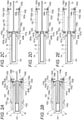
- Figs. 2A to 2E are schematic diagrams for describing a structure and an extending and retracting operation of the telescopic boom 14.
- Fig. 1 illustrates the telescopic boom 14 in an extended state.
- Fig. 2A illustrates the telescopic boom 14 in a retracted state.
- Fig. 2E illustrates the telescopic boom 14 in which only the tip boom element 141 to be described later is extended.
- the telescopic boom 14 includes a plurality of boom elements.
- Each of the plurality of boom elements has a tubular shape.
- the plurality of boom elements are combined with each other in a telescopic shape.
- the plurality of boom elements are a tip boom element 141, an intermediate boom element 142, and a proximal-end boom element 143 in order from the inside.
- the tip boom element 141 and the intermediate boom element 142 correspond to an example of a first boom element movable in the telescopic direction.
- the tip boom element 141 moves in a telescopic direction with respect to the intermediate boom element 142
- the tip boom element 141 corresponds to an example of the first boom element
- the intermediate boom element 142 corresponds to an example of a second boom element.
- the intermediate boom element 142 moves in the telescopic direction with respect to the proximal-end boom element 143
- the intermediate boom element 142 corresponds to an example of the first boom element
- the proximal-end boom element 143 corresponds to an example of the second boom element. Movement of the proximal-end boom element 143 in the telescopic direction is restricted.
- the state of the telescopic boom transitions from the retracted state illustrated in Fig. 2A to the extended state illustrated in Fig. 1 by sequentially extending the telescopic boom 14 from the boom element (that is, the tip boom element 141) disposed on the inner side.
- the intermediate boom element 142 is disposed between the proximal-end boom element 143 on the most proximal-end side and the tip boom element 141 on the most tip side. Note that a plurality of intermediate boom elements may be provided.
- the structure of the telescopic boom 14 is substantially the same as the structure of the telescopic boom known in the related art, but for convenience of description of the structure and operation of the actuator 2 to be described later, the structures of the tip boom element 141 and the intermediate boom element 142 will be described below.
- the tip boom element 141 has a tubular shape as illustrated in Figs. 2A to 2E .
- the tip boom element 141 has an internal space capable of accommodating the actuator 2.
- the tip boom element 141 has a pair of cylinder pin receiving parts 141a and a pair of boom pin receiving parts 141b at a proximal end portion
- the pair of cylinder pin receiving parts 141a is provided coaxially with each other at the proximal end portion of the tip boom element 141.
- Each of the pair of cylinder pin receiving parts 141a can be engaged with and disengaged from a pair of cylinder connecting pins 454a and 454b (also referred to as a first connecting member.) provided in a cylinder member 32 of a telescopic cylinder 3. That is, the pair of cylinder pin receiving parts 141a can take either an engaged state of being engaged with the pair of cylinder connecting pins 454a and 454b or a disengaged state of being disengaged from the pair of cylinder connecting pins 454a and 454b.
- the cylinder connecting pins 454a and 454b move in an axial direction thereof based on an operation of a cylinder connecting mechanism 45 included in the actuator 2 to be described later.
- the tip boom element 141 is movable in the telescopic direction together with the cylinder member 32.
- the pair of boom pin receiving parts 141b is provided coaxially with each other on the proximal-end side of the cylinder pin receiving part 141a.
- Each of the boom pin receiving parts 141b can be engaged with and disengaged from the pair of boom connecting pins 144a (also referred to as a second connecting member.). That is, the pair of boom pin receiving parts 141b can take either an engaged state of being engaged with the pair of boom connecting pins 144a or a disengaged state of being disengaged from the pair of boom connecting pins 144a.
- Each of the pair of boom connecting pins 144a connects the tip boom element 141 and the intermediate boom element 142.
- the pair of boom connecting pins 144a moves in the axial direction thereof based on an operation of a boom connecting mechanism 46 included in the actuator 2.
- the pair of boom connecting pins 144a may be regarded as constituent members of the boom connecting mechanism 46 (see Fig. 3B ).
- the boom connecting pin 144a is inserted so as to be bridged between the boom pin receiving part 141b of the tip boom element 141 and a first boom pin receiving part 142b or a second boom pin receiving part 142c of the intermediate boom element 142 to be described later.
- the tip boom element 141 In a state where the tip boom element 141 and the intermediate boom element 142 are connected (also referred to as a connected state.), the tip boom element 141 is prohibited from moving in the telescopic direction with respect to the intermediate boom element 142.
- the tip boom element 141 and the intermediate boom element 142 are disconnected (also referred to as a disconnected state.)
- the tip boom element 141 can move in the telescopic direction with respect to the intermediate boom element 142.
- the intermediate boom element 142 has a cylindrical shape as illustrated in Figs. 2A to 2E .
- the intermediate boom element 142 has an internal space capable of accommodating the tip boom element 141.
- the intermediate boom element 142 has a pair of cylinder pin receiving parts 142a, a pair of first boom pin receiving parts 142b, a pair of second boom pin receiving parts 142c, and a pair of third boom pin receiving parts 142d at the proximal end portion.
- the pair of cylinder pin receiving parts 142a and the pair of first boom pin receiving parts 142b are substantially similar to the pair of cylinder pin receiving parts 141a and the pair of boom pin receiving parts 141b of the tip boom element 141, respectively.
- the pair of third boom pin receiving parts 142d is provided coaxially with each other on the proximal-end side of the pair of first boom pin receiving parts 142b.
- a pair of boom connecting pins 144b is inserted into the pair of third boom pin receiving parts 142d, respectively.
- the pair of boom connecting pins 144b connects the intermediate boom element 142 and the proximal-end boom element 143.
- the pair of second boom pin receiving parts 142c is provided coaxially with each other at the tip portion of the intermediate boom element 142.
- the pair of boom connecting pins 144a is inserted into the pair of second boom pin receiving parts 142c, respectively.
- the actuator 2 is an actuator that extends and retracts the above-described telescopic boom 14 (see Figs. 1 and 2A to 2E ).
- the actuator 2 includes the telescopic cylinder 3 and a pin moving module 4.
- the actuator 2 is disposed in the internal space of the tip boom element 141 in the retracted state of the telescopic boom 14 (the state illustrated in Fig. 2A ).
- the telescopic cylinder 3 includes a rod member 31 (also referred to as a fixing-side member. See Figs. 2A to 2E ) and the cylinder member 32 (also referred to as a movable side member.).
- the telescopic cylinder 3 moves a boom element (for example, the tip boom element 141 or the intermediate boom element 142) connected to the cylinder member 32 via the cylinder connecting pins 454a and 454b to be described later in the telescopic direction. Since the structure of the telescopic cylinder 3 is substantially similar to the structure of the conventionally known telescopic cylinder, a detailed description thereof will be omitted.
- the pin moving module 4 includes a housing 40, an electric motor 41, a brake mechanism 42, a transmission mechanism 43, a position information detection device 44, a cylinder connecting mechanism 45, a boom connecting mechanism 46, and a lock mechanism 47 (see Fig. 8 ).
- each member constituting the actuator 2 will be described with reference to a state of being incorporated in the actuator 2.
- an orthogonal coordinate system (X, Y, Z) illustrated in each drawing is used.
- the arrangement of each unit constituting the actuator 2 is not limited to the arrangement of the present embodiment.
- an X direction coincides with the telescopic direction of the telescopic boom 14 mounted on the mobile crane 1.
- a + side in the X direction is also referred to as an extending direction in the telescopic direction.
- a - side in the X direction is also referred to as a retracting direction in the telescopic direction.
- a Z direction coincides with a vertical direction of the mobile crane 1 in a state where a derricking angle of the telescopic boom 14 is 0 (also referred to as a fallen state of the telescopic boom 14.).
- a Y direction coincides with a vehicle width direction of the mobile crane 1 in a state where the telescopic boom 14 faces forward.
- the Y direction and the Z direction are not limited to the above directions as long as they are two directions orthogonal to each other.
- the housing 40 is fixed to the cylinder member 32 of the telescopic cylinder 3.
- the housing 40 accommodates the cylinder connecting mechanism 45 and the boom connecting mechanism 46 in the internal space.
- the housing 40 supports the electric motor 41 via the transmission mechanism 43. Furthermore, the housing 40 also supports a brake mechanism 42 to be described later.
- Such a housing 40 unitizes each of the above-described elements. Such a configuration contributes to miniaturization of the pin moving module 4, improvement in productivity, and improvement in system reliability.
- the housing 40 has a box-shaped first housing element 400 and a box-shaped second housing element 401.
- the first housing element 400 accommodates the cylinder connecting mechanism 45 to be described later in the internal space.
- the rod member 31 is inserted through the first housing element 400 in the X direction.
- An end portion of the cylinder member 32 is fixed to a side wall of the first housing element 400 on the + side in the X direction (the left side in Fig. 4 and the right side in Fig. 7 ).
- the first housing element 400 has through holes 400a and 400b (see Figs. 3B and 7 ) in side walls on both sides in the Y direction.
- a pair of cylinder connecting pins 454a and 454b of the cylinder connecting mechanism 45 is inserted into the through holes 400a and 400b, respectively.
- the second housing element 401 is provided on a + side in the Z direction of the first housing element 400.
- the second housing element 401 accommodates the boom connecting mechanism 46 to be described later in the internal space.
- a second transmission shaft 433 (see Fig. 8 ) of the transmission mechanism 43 to be described later is inserted into the second housing element 401 in the X direction.
- the second housing element 401 has through holes 401a and 401b (see Figs. 3B and 7 ) in side walls on both sides in the Y direction.
- a pair of second rack bars 461a and 461b of the boom connecting mechanism 46 are inserted into the through holes 401a and 401b, respectively.
- the electric motor 41 corresponds to an example of an electric drive source, and is supported by the housing 40 via a speed reducer 431 of the transmission mechanism 43. Specifically, the electric motor 41 is disposed around the cylinder member 32 (for example, + side in the Z direction) and around the second housing element 401 (for example, the - side in the X direction) in a state where an output shaft (not illustrated) is parallel to the X direction (also referred to as a longitudinal direction of the cylinder member 32.). Such an arrangement contributes to miniaturization of the pin moving module 4 in the Y direction and the Z direction.
- the electric motor 41 as described above is connected to, for example, a power supply device provided on the turning table 12 via a power supply cable. Furthermore, the electric motor 41 is connected to, for example, a control unit 44b (see Fig. 1 ) provided on a turning table 12 via a control signal transmission cable.
- Each of the above-described cables can be unreeled and wound by a cord reel that is provided outside the proximal end portion of the telescopic boom 14 or on the turning table 12 (see Fig. 1 ).
- the electric motor 41 includes manual operation unit 410 (see Fig. 3B ) that can be operated by a manual handle (not illustrated).
- the manual operation unit 410 is for manually performing the state transition of the pin moving module 4.
- an output shaft of the electric motor 41 rotates and the state of the pin moving module 4 transitions.
- the number of electric motors may be one or plural (for example, two).
- the cylinder connecting mechanism 45 and the boom connecting mechanism 46 operate by one electric motor 41.
- the first electric motor (not illustrated) may operate the cylinder connecting mechanism 45
- the second electric motor (not illustrated) may operate the boom connecting mechanism 46.
- the electric drive source is the electric motor 41 described above.
- the electric drive source is not limited to the electric motor.
- the electric drive source may be various drive sources that generate driving force based on energization from a power source.
- the brake mechanism 42 applies a braking force to the electric motor 41.
- the brake mechanism 42 prevents the rotation of the output shaft of the electric motor 41 while the electric motor 41 stops. As a result, the state of the pin moving module 4 is maintained in the stopped state of the electric motor 41.
- the brake mechanism 42 may allow the rotation (that is, sliding) of the electric motor 41 when an external force of a predetermined magnitude acts on the cylinder connecting mechanism 45 or the boom connecting mechanism 46 at the time of braking.
- Such a configuration contributes to prevention of damage to the electric motor 41, each gear, or the like that constitute the actuator 2.
- a friction brake can be adopted as the brake mechanism 42.
- the brake mechanism 42 operates in the retracted state of the cylinder connecting mechanism 45 or the retracted state of the boom connecting mechanism 46 to be described later to maintain the states of the cylinder connecting mechanism 45 and the boom connecting mechanism 46.
- the brake mechanism 42 is disposed in front of the transmission mechanism 43 to be described later. Specifically, the brake mechanism 42 is disposed coaxially with the output shaft of the electric motor 41 on the - side in the X direction (that is, the side opposite to the transmission mechanism 43 with the electric motor 41 as the center) with respect to the electric motor 41 (see Fig. 3B ) .
- a front stage means an upstream side (side close to the electric motor 41) in a transmission path through which the power of the electric motor 41 is transmitted to the cylinder connecting mechanism 45 or the boom connecting mechanism 46.
- a rear stage means a downstream side (side far from the electric motor 41) in a transmission path through which the power of the electric motor 41 is transmitted to the cylinder connecting mechanism 45 or the boom connecting mechanism 46.
- a brake torque necessary for maintaining the stopped state of the electric motor 41 is smaller in the configuration in which the brake mechanism 42 is disposed at the front stage of the transmission mechanism 43 than in the configuration in which the brake mechanism 42 is disposed at the rear stage of the transmission mechanism 43 (a speed reducer 431 to be described later). For this reason, the configuration in which the brake mechanism 42 is disposed at the front stage of the transmission mechanism 43 contributes to downsizing of the brake mechanism 42.
- the brake mechanism 42 may be various brake devices such as a mechanical brake device and an electromagnetic brake device.
- the position of the brake mechanism 42 is not limited to the position of the present embodiment.
- the transmission mechanism 43 transmits power (that is, rotational motion) of the electric motor 41 to the cylinder connecting mechanism 45 and the boom connecting mechanism 46. As illustrated in Figs. 17A to 17C , the transmission mechanism 43 includes a speed reducer 431, a first transmission shaft 432, a coupling 6, and a second transmission shaft 433.
- the speed reducer 431 decelerates the rotation of the electric motor 41 and transmits the decelerated rotation to the first transmission shaft 432.
- the speed reducer 431 is, for example, a planetary gear mechanism housed in a speed reducer case 431a.
- the speed reducer 431 is provided coaxially with the output shaft of the electric motor 41. Such an arrangement contributes to miniaturization of the pin moving module 4 in the Y direction and the Z direction.
- the first transmission shaft 432 is a shaft-like member, and has an engaging part 432a (see Fig. 23A ) at one end portion (end portion on the + side in the X direction) of an outer peripheral surface thereof.
- the engaging part 432a is, for example, a ridge extending in the axial direction of the first transmission shaft 432.
- One end portion of the first transmission shaft 432 is connected to a drive-side element 61 of the coupling 6 to be described later.
- the other end portion (end portion on the - side in the X direction) of the first transmission shaft 432 is connected to an output shaft (not illustrated) of the speed reducer 431.
- the first transmission shaft 432 rotates together with the output shaft of the speed reducer 431. It may be understood that the first transmission shaft 432 rotates on the basis of the power of the electric motor 41.
- the first transmission shaft 432 transmits the rotation of the output shaft of the speed reducer 431 to the drive-side element 61. Note that the first transmission shaft 432 may be integrated with the output shaft of the speed reducer 431.
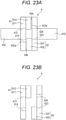
- the coupling 6 will be described with reference to Figs. 23A, 23B , 24A, and 24B .
- the coupling 6 has the drive-side element 61 and a driven-side element 62.
- the drive-side element 61 includes a drive-side base part 611 and a drive-side transmission part 612.
- the drive-side base part 611 may have, for example, a disk shape.
- the drive-side base part 611 has a through hole 613 penetrating the drive-side base part 611 in a thickness direction at the center thereof.
- the through hole 613 has a locking groove 614 on an inner peripheral surface thereof.
- One end portion of the first transmission shaft 432 is inserted into the through hole 613. In this state, the locking groove 614 is engaged with the engaging part 432a of the first transmission shaft 432. Therefore, both the first transmission shaft 432 and the drive-side base part 611 (the drive-side element 61) are rotatable. It may be understood that the drive-side element 61 rotates on the basis of the power of the electric motor 41.
- the drive-side transmission part 612 is provided on one end face (surface on the + side in the X direction) of the drive-side base part 611.
- the drive-side transmission part 612 is a substantially fan-shaped protrusion.
- the drive-side transmission part 612 has a first transmission surface 615 on one end face of the drive-side element 61 in a circumferential direction.
- the drive-side transmission part 612 has a second transmission surface 616 on the other end face of the drive-side element 61 in the circumferential direction.
- the driven-side element 62 includes a driven-side base part 621 and a driven-side transmission part 622.
- the driven-side base part 621 may have, for example, a disk shape.
- the driven-side base part 621 has a through hole 623 penetrating the driven-side base part 621 in the thickness direction at the center thereof.
- the through hole 623 has a locking groove 624 on an inner peripheral surface thereof.
- One end portion of the second transmission shaft 433 is inserted into the through hole 623. In this state, the locking groove 624 is engaged with the engaging part 433a of the second transmission shaft 433. Therefore, both the second transmission shaft 433 and the driven-side base part 621 (the driven-side element 62) are rotatable. It may be understood that the driven-side element 62 is connected to the cylinder connecting mechanism 45 and the boom connecting mechanism 46 to be described later
- the driven-side transmission part 622 is provided on one end face (surface on the - side in the X direction) of the driven-side base part 621.
- the driven-side transmission part 622 is a substantially fan-shaped protrusion provided on one end face of the driven-side base part 621.
- the driven-side transmission part 622 has a first transmission surface 625 on one end face of the driven-side element 62 in the circumferential direction.
- the driven-side transmission part 622 has a second transmission surface 626 on the other end face of the driven-side element 62 in the circumferential direction.
- the drive-side element 61 and the driven-side element 62 as described above are disposed such that one end faces thereof face each other in the X direction.
- the drive-side transmission part 612 of the drive-side element 61 and the driven-side transmission part 622 of the driven-side element 62 can take a state (hereinafter, referred to as an "engaged state.") of being engaged in a rotation direction (also referred to as a circumferential direction.) of the drive-side element 61 and the driven-side element 62 and a state (hereinafter, referred to as a "disengaged state.”) of being separated in the rotation direction.
- a gap 64a is provided between the drive-side transmission part 612 of the drive-side element 61 and the driven-side base part 621 of the driven-side element 62.
- a gap 64b is provided between the driven-side transmission part 622 of the driven-side element 62 and the drive-side base part 611 of the drive-side element 61. That is, in the assembled state, the drive-side element 61 and the driven-side element 62 are not in contact with each other in the X direction. Such gaps 64a and 64b may eliminate sliding resistance between the drive-side element 61 and the driven-side element 62.
- Such an engaged state corresponds to the transmission state of the coupling 6, in which the drive-side element 61 and the driven-side element 62 rotate together. Specifically, in the engaged state, the rotation of one of the drive-side element 61 and the driven-side element 62 is transmitted to the other element, so the drive-side element 61 and the driven-side element 62 rotate together.
- Such an engaged state corresponds to the transmission state of the coupling 6 in which power can be transmitted between the drive-side element 61 and the driven-side element 62.
- the second transmission shaft 433 is a shaft member, and has an engaging part 433a (see Fig. 23A ) at one end portion (end portion on the - side in the X direction) of the outer peripheral surface thereof
- the engaging part 433a is, for example, a ridge extending in the axial direction of the second transmission shaft 433.
- One end portion (end portion on the - side in the X direction) of the second transmission shaft 433 is connected to the driven-side element 62 of the coupling 6.
- the second transmission shaft 433 extends in the X direction and is inserted into the housing 40 (specifically, the second housing element 401).
- An end portion of the second transmission shaft 433 on the + side in the X direction protrudes to the + side in the X direction from the housing 40.
- a position information detection device 44 to be described later is provided at an end portion of the second transmission shaft 433 on the + side in the X direction.
- the position information detection device 44 detects information on the positions of the pair of cylinder connecting pins 454a and 454b and the pair of boom connecting pins 144a (the pair of boom connecting pins 144b may be used. The same applies hereinafter.) based on the output (for example, the rotation of the output shaft) of the electric motor 41.
- the information on the position may be, for example, a movement amount of the pair of cylinder connecting pins 454a and 454b or the pair of boom connecting pins 144a from a reference position (the position illustrated in Figs. 17A and 18A ).
- the position information detection device 44 detects the information on the positions of the pair of cylinder connecting pins 454a and 454b in the engaged state (for example, the state illustrated in Fig. 2A ) or the disengaged state (the state illustrated in Fig. 2E ) between the pair of cylinder connecting pins 454a and 454b and the pair of cylinder pin receiving parts 141a of the boom element (for example, the tip boom element 141).
- the position information detection device 44 detects the information on the positions of the pair of boom connecting pins 144a in the engaged state (for example, the state illustrated in Figs. 2A and 2D ) or the disengaged state (for example, the state illustrated in Fig. 2B ) between the pair of boom connecting pins 144a and the pair of first boom pin receiving parts 142b (the pair of second boom pin receiving parts 142c may be used.
- the boom element for example, the intermediate boom element 142).
- the information on the positions of the pair of cylinder connecting pins 454a and 454b and the pair of boom connecting pins 144a and 144b detected in this manner is used for various controls of the actuator 2 including operation control of the electric motor 41, for example.
- the position information detection device 44 includes a detection unit 44a and a control unit 44b (see Figs. 17A and 18A ).
- the detection unit 44a is, for example, a rotary encoder, and outputs information (for example, a pulse signal and a code signal) corresponding to the rotation amount of the output shaft of the electric motor 41.
- the output method of the rotary encoder is not particularly limited, and may be an incremental method of outputting a pulse signal (relative angle signal) according to the rotation amount (rotation angle) from a measurement start position, or an absolute method of outputting a code signal (absolute angle signal) corresponding to an absolute angle position with respect to the reference point.
- the position information detection device 44 can detect the information on the positions of the pair of cylinder connecting pins 454a, 454b and the pair of boom connecting pins 144a.
- the detection unit 44a may be provided on the output shaft of the electric motor 41.
- the detection unit 44a may be provided on a rotating member (for example, a rotation shaft, a gear, or the like) that rotates together with the output shaft of the electric motor 41.
- the detection unit 44a is provided at an end portion of the second transmission shaft 433 on the + side in the X direction.
- the detection unit 44a is provided at a stage (that is, the + side in the X direction) subsequent to the speed reducer 431.
- the detection unit 44a outputs information corresponding to the rotation amount of the second transmission shaft 433.
- a rotary encoder capable of obtaining sufficient resolution with respect to a rotation number (rotation speed) of the second transmission shaft 433 is adopted as the detection unit 44a. Note that since a first toothless gear 450 of the cylinder connecting mechanism 45 and a second toothless gear 460 of the boom connecting mechanism 46, which will be described later, are fixed to the transmission shaft 432, the output information of the detection unit 44a is also information corresponding to the rotation amounts of the first toothless gear 450 and the second toothless gear 460.
- the detection unit 44a having the above configuration sends the detection value to the control unit 44b.
- the control unit 44b that has acquired the information calculates the information on the positions of the pair of cylinder connecting pins 454a and 454b or the pair of boom connecting pins 144a based on the acquired information. Then, the control unit 44b controls the electric motor 41 based on the calculation result.
- the control unit 44b is, for example, an in-vehicle computer including an input terminal, an output terminal, a CPU, a memory, and the like.
- the control unit 44b calculates the information on the positions of the pair of cylinder connecting pins 454a and 454b or the boom connecting pin 144a based on the output of the detection unit 44a.
- control unit 44b calculates the information on the position using data (tables, maps, or the like) indicating a correlation between the output of the detection unit 44a and the information (for example, the movement amount from the reference position) on the positions of the pair of cylinder connecting pins 454a and 454b and the pair of boom connecting pins 144a.
- the information on the position is calculated based on data (tables, maps, or the like) indicating a correlation between each code signal and the movement amount of the pair of cylinder connecting pins 454a and 454b and the pair of boom connecting pins 144a from the reference position.
- the control unit 44b as described above is provided on the turning table 12. However, the position of the control unit 44b is not limited to the turning table 12.
- the control unit 44b may be provided, for example, in a case (not illustrated) in which the detection unit 44a is disposed.
- the position of the detection unit 44a is not limited to the position of the present embodiment.
- the detection unit 44a may be disposed in front of the speed reducer 431 (that is, the - side in the X direction). That is, the detection unit 44a may acquire information to be sent to the control unit 44b based on the rotation of the electric motor 41 before being decelerated by the speed reducer 431.
- the resolution of the detection unit 44a is higher in the configuration in which the detection unit 44a is disposed at the front stage of the speed reducer 431 than in the configuration in which the detection unit 44a is disposed at the rear stage of the speed reducer 431.
- the detection unit 44a is not limited to the above-described rotary encoder.
- the detection unit 44a may be a limit switch.
- the limit switch is disposed at the stage subsequent to the speed reducer 431. Such a limit switch mechanically operates based on the output of the electric motor 41.
- the detection unit 44a may be a proximity sensor.
- the proximity sensor is disposed at the stage subsequent to the speed reducer 431.
- the proximity sensor is disposed to face a member that rotates on the basis of the output of the electric motor 41. Such a proximity sensor outputs a signal based on the distance from the rotating member.
- the control unit 44b controls the operation of the electric motor 41 based on the output of the limit switch or the proximity sensor.
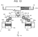
- the cylinder connecting mechanism 45 corresponds to an example of an operating unit, operates based on power (that is, rotational motion) of the electric motor 41, and performs a state transition between an extended state (also referred to as a first state. See Fig. 8 and Fig. 12 ) and a retracted state (also referred to as a second state. See Fig. 13 ).
- the pair of cylinder connecting pins 454a and 454b to be described later and the pair of cylinder pin receiving parts 141a of the boom element are in the engaged state (also referred to as a state in which a cylinder pin is inserted.).
- the engaged state the boom element and the cylinder member 32 are connected.
- the pair of cylinder connecting pins 454a and 454b and the pair of cylinder pin receiving parts 141a are in the separated state (the state illustrated in Fig. 2E , and also referred to as a pulled state of a cylinder pin.).
- the boom element and the cylinder member 32 are in the disconnected state.
- the cylinder connecting mechanism 45 includes a first toothless gear 450, a first rack bar 451, a first gear mechanism 452, a second gear mechanism 453, a pair of cylinder connecting pins 454a and 454b, and a first urging mechanism 455.
- Each of the elements 450, 451, 452, and 453 corresponds to an example of a constituent member of the first drive mechanism.
- the pair of cylinder connecting pins 454a and 454b is incorporated in the cylinder connecting mechanism 45.
- the pair of cylinder connecting pins 454a and 454b may be provided independently of the cylinder connecting mechanism 45.
- the first toothless gear 450 (also referred to as a switch gear.) has a substantially disk shape.
- the first toothless gear 450 has a first tooth part 450a (see Fig. 9 ) on a portion of an outer peripheral surface thereof.
- the first toothless gear 450 is externally fitted and fixed to the second transmission shaft 433 and rotates together with the second transmission shaft 433.
- Such a first toothless gear 450 constitutes a switch gear together with the second toothless gear 460 (see Fig. 8 ) of the boom connecting mechanism 46.
- the switch gear selectively transmits the power of the electric motor 41 to any one of the cylinder connecting mechanism 45 and the boom connecting mechanism 46.
- first toothless gear 450 and the second toothless gear 460 which are switch gears
- the cylinder connecting mechanism 45 which is a first connecting mechanism
- the boom connecting mechanism 46 which is a second connecting mechanism.
- the switch gear may be provided independently of the first connecting mechanism and the second connecting mechanism.
- a rotation direction (direction of arrow F 2 in Figs. 17A to 17C ) of the first toothless gear 450 is a "front side" in the rotation direction of the first toothless gear 450.
- the rotation direction of the first toothless gear 450 (direction of arrow F 1 in Figs. 17A to 17C ) at the time of state transition from the retracted state to the extended state is a "rear side" in the rotation direction of the first toothless gear 450.
- the protrusion provided on the foremost side in the rotation direction of the first toothless gear 450 is a positioning tooth (not illustrated).
- a first rack bar 451 moves in its longitudinal direction (also referred to as a Y direction.) in accordance with the rotation of the first toothless gear 450.
- the first rack bar 451 is located closest to a - side in the Y direction in the extended state (see Figs. 8 and 12 ).
- the first rack bar 451 is located closest to a + side in the Y direction in the retracted state (see Fig. 13 ).
- first rack bar 451 moves toward the - side in the Y direction (also referred to as the other side in the longitudinal direction.). A specific configuration of first rack bar 451 will be described below.
- the first rack bar 451 is, for example, a shaft member elongated in the Y direction, and is disposed between the first toothless gear 450 and the rod member 31. In this state, the longitudinal direction of the first rack bar 451 coincides with the Y direction.
- the first rack bar 451 has a first rack tooth part 451a (see Fig. 8 ) on a surface closer to the first toothless gear 450 (also referred to as a + side in the Z direction.).
- the first rack tooth part 451a meshes with the first tooth part 450a of the first toothless gear 450 only during the above-described state transition.
- a first end face (not illustrated) of the first rack tooth part 451a on the + side in the Y direction abuts on the positioning tooth (not illustrated) of the first tooth part 450a of the first toothless gear 450 or faces the positioning tooth (not illustrated) in the Y direction with a slight gap interposed therebetween.
- the positioning tooth 450b presses the first end face toward the + side in the Y direction, and the first rack bar 451 moves toward the + side in the Y direction.
- the tooth part of the first tooth part 450a located behind the positioning tooth in the rotation direction meshes with the first rack tooth part 451a.
- the first rack bar 451 moves to the + side in the Y direction in accordance with the rotation of the first toothless gear 450.
- the first rack bar 451 has a second rack tooth part 451b and a third rack tooth part 451c (see Fig. 13 ) on a surface on a side (also referred to as a - side in the Z direction.) far from the first toothless gear 450.
- the second rack tooth part 451b meshes with a first gear mechanism 452 to be described later.
- the third rack tooth part 451c meshes with a second gear mechanism 453 to be described later.
- the first gear mechanism 452 includes a plurality of (3 in the case of the present embodiment) gear elements 452a, 452b, and 452c (see Fig. 8 ) each of which is a spur gear.
- the gear element 452a meshes with the second rack tooth part 451b of the first rack bar 451 and the gear element 452b.
- the gear element 452a meshes with the tooth part at the end portion on the + side in the Y direction or the portion close to the end portion in the second rack tooth part 451b of the first rack bar 451.
- the gear element 452b meshes with the gear element 452a and the gear element 452c.
- the gear element 452c meshes with the gear element 452b and a pin-side rack tooth part 454c of one cylinder connecting pin 454a to be described later.
- the gear element 452c meshes with the end portion on the - side in the Y-direction in the pin-side rack tooth part 454c (see Fig. 8 ) of one cylinder connecting pin 454a.
- the second gear mechanism 453 includes a plurality of (in the case of the present embodiment, two) gear elements 453a and 453b (see Fig. 8 ) each of which is a spur gear. Specifically, the gear element 453a meshes with the third rack tooth part 451c of the first rack bar 451 and the gear element 453b. In the extended state, the gear element 453a meshes with the end portion on the + side in the Y direction of the third rack tooth part 451c of the first rack bar 451.
- the gear element 453b meshes with the gear element 453a and a pin-side rack tooth part 454d (see Fig. 8 ) of the other cylinder connecting pin 454b to be described later.
- the gear element 453b meshes with the end portion on the + side in the Y direction of the pin-side rack tooth part 454d of the other cylinder connecting pin 454b.
- the rotation direction of the gear element 452c of the first gear mechanism 452 is opposite to the rotation direction of the gear element 453b of the second gear mechanism 453.
- a central axis of each of the pair of cylinder connecting pins 454a and 454b coincides with the Y direction and is coaxial with each other.
- the tip portion is an end portion on a side far from each other, and the proximal end portion is an end portion on a side close to each other.
- Each of the pair of cylinder connecting pins 454a and 454b has pin-side rack tooth parts 454c and 454d (see Fig. 8 ) on the outer peripheral surface thereof.
- the pin-side rack tooth part 454c of one (also referred to as the + side in the Y direction.) cylinder connecting pin 454a meshes with the gear element 452c of the first gear mechanism 452.
- One cylinder connecting pin 454a moves in its own axial direction (that is, the Y direction) as the gear element 452c in the first gear mechanism 452 rotates. Specifically, one cylinder connecting pin 454a moves to the + side in the Y direction (also referred to as a second direction.) when the state transitions from the retracted state to the extended state. On the other hand, one cylinder connecting pin 454a moves to the - side in the Y direction (also referred to as a first direction.) when the state transitions from the extended state to the retracted state.
- the pin-side rack tooth part 454d of the other also referred to as the - side in the "Y direction."
- cylinder connecting pin 454b meshes with the gear element 453b of the second gear mechanism 453.
- the other cylinder connecting pin 454b moves in its own axial direction (that is, the Y direction) as the gear element 453b in the second gear mechanism 453 rotates.
- the other cylinder connecting pin 454b moves to the - side in the Y direction (also referred to as a second direction.) when the state transitions from the retracted state to the extended state.
- the other cylinder connecting pin 454b moves to the + side in the Y direction (also referred to as a first direction.) when the state transitions from the extended state to the retracted state. That is, in the above-described state transition, the pair of cylinder connecting pins 454a and 454b moves in directions opposite to each other in the Y direction.
- the pair of cylinder connecting pins 454a and 454b are respectively inserted into the through holes 400a and 400b of the first housing element 400. In this state, the tip portions of the pair of cylinder connecting pins 454a and 454b protrude to the outside of the first housing element 400.
- a first urging mechanism 455 automatically returns the cylinder connecting mechanism 45 to the extended state when the electric motor 41 is in the non-energized state in the retracted state of the cylinder connecting mechanism 45. Therefore, the first urging mechanism 455 urges the pair of cylinder connecting pins 454a and 454b in directions away from each other. Note that the first urging mechanism 455 may directly apply a force to the cylinder connecting pins 454a and 454b, or may apply a force via another member. In addition, the first urging mechanism 455 may be omitted. In this case, the cylinder connecting mechanism 45 may make a state transition from the retracted state to the extended state based on the power of the electric motor 41.
- the first urging mechanism 455 includes a pair of coil springs 455a and 455b (see Fig. 8 ). Each of the pair of coil springs 455a and 455b urges the pair of cylinder connecting pins 454a and 454b toward the tip side. Each of the pair of coil springs 455a and 455b corresponds to an example of a first urging member.
- FIGS. 17A to 17C are schematic diagrams for describing the operation of the cylinder connecting mechanism 45. Further, in addition to the description of the operation of the cylinder connecting mechanism 45, the operation of the coupling 6 will be described with reference to Figs. 19A to 19D and Figs. 20A to 20D . Note that Figs. 19A to 19D and Figs. 20A to 20D are schematic diagrams of the coupling 6 when viewed from the - side in the X direction.
- Fig. 17A is a schematic diagram illustrating an extended state of the cylinder connecting mechanism 45 and an engaged state between the pair of cylinder connecting pins 454a and 454b and the pair of cylinder pin receiving parts 141a of the tip boom element 141.
- Fig. 17B is a schematic diagram illustrating a state in the middle of the state transition of the cylinder connecting mechanism 45 from the extended state to the retracted state.
- Fig. 17C is a schematic diagram illustrating a retracted state of the cylinder connecting mechanism 45 and a separated state between the pair of cylinder connecting pins 454a and 454b and the pair of cylinder pin receiving parts 141a of the tip boom element 141.
- the cylinder connecting mechanism 45 makes a state transition between an extended state (see Figs. 8 , 12 , and 17A ) and a retracted state (see Figs. 13 and 17C ) based on the power (that is, rotational motion) of the electric motor 41.
- the operation of each unit when the cylinder connecting mechanism 45 transitions from the extended state to the retracted state will be described with reference to Figs. 17A to 17C .
- first toothless gear 450 and the second toothless gear 460 are schematically illustrated as an integrated toothless gear.
- the integrated toothless gear will be described as the first toothless gear 450.
- the lock mechanism 47 to be described later is omitted.
- the first path is a path of the first toothless gear 450 ⁇ the first rack bar 451 ⁇ the first gear mechanism 452 ⁇ one cylinder connecting pin 454a.
- the second path is a path of the first toothless gear 450 ⁇ the first rack bar 451 ⁇ the second gear mechanism 453 ⁇ the other cylinder connecting pin 454b.
- the drive-side element 61 of the coupling 6 rotates in the first direction (direction of arrow A 6a in Fig. 19A ) via the speed reducer 431 and the first transmission shaft 432.
- the positions of the drive-side element 61 and the driven-side element 62 illustrated in Fig. 19A are defined as neutral positions in the coupling 6.
- the neutral position in the coupling 6 means a state in which the drive-side element 61 and the driven-side element 62 are not engaged. Therefore, the position of the drive-side element 61 corresponding to the neutral position of the coupling 6 is not limited to the position in Fig. 19A .
- both the drive-side element 61 and the driven-side element 62 rotate in the first direction. That is, the rotation of the drive-side element 61 is transmitted to the driven-side element 62.
- the state illustrated in Figs. 19C and 19D corresponds to an example of the transmission state of the coupling 6.
- the first toothless gear 450 rotates on the front side in the rotation direction (direction of arrow F 2 in Fig. 17A ) in the first path and the second path.
- the direction of arrow A 6a in Figs. 19A to 19C corresponds to the direction of arrow F 2 in Fig. 17A .
- the position information detection device 44 detects that the pair of cylinder connecting pins 454a and 454b is separated from the pair of cylinder pin receiving parts 141a of the tip boom element 141 and moved to a predetermined position (for example, the position illustrated in Figs. 2E and 17C ). Then, based on the detection result, the control unit 44b stops the operation of the electric motor 41.
- the drive-side element 61 and the driven-side element 62 are in a state illustrated in Fig. 19D .
- the driven-side element 62 stops by being restricted from rotating in the first direction by the stopper 63a.
- the drive-side element 61 also stops. Then, by turning the electric motor 41 to the OFF state and turning the brake mechanism 42 to the ON state, the retracted state of the cylinder connecting mechanism 45 is maintained.
- the coupling 6 is maintained in the state illustrated in Fig. 19D .
- the stopper 63a is not necessarily provided on the coupling 6.
- the stopper 63a may not be a member that directly abuts on the driven-side element 62 to prevent the rotation of the driven-side element 62 in the direction of the arrow A 6a . That is, the stopper 63a may be a member that prevents the rotation of the driven-side element 62 in the direction of the arrow A 6a as a result of the stopper 63a abutting on a member other than the driven-side element 62.
- the brake mechanism 42 is set to the OFF state while maintaining the OFF state of the electric motor 41. Then, based on the urging force of the first urging mechanism 455, one cylinder connecting pin 454a and the other cylinder connecting pin 454b move in directions away from each other. As one cylinder connecting pin 454a and the other cylinder connecting pin 454b move, the first toothless gear 450 rotates in the direction of the arrow F 1 in Fig. 17C .
- the rotation of the first toothless gear 450 is transmitted to the driven-side element 62 of the coupling 6 via the second transmission shaft 433, and the driven-side element 62 rotates in a direction of arrow A 6b in Fig. 20A .
- the rotation of the driven-side element 62 is transmitted to the drive-side element 61, and the drive-side element 61 and the driven-side element 62 rotate in the direction of the arrow A 6b in Fig. 20A .
- the direction of arrow A 6b in Fig. 20A corresponds to the direction of arrow F 1 in Figs. 17A to 17C .
- the state illustrated in Figs. 20A to 20C corresponds to an example of the transmission state of the coupling 6.
- the driven-side element 62 passes through the position illustrated in Fig. 20B and stops at the position illustrated in Fig. 20C while being restricted in rotation by the stopper 63b.
- the cylinder connecting mechanism 45 transitions from the state illustrated in Fig. 17C to the state illustrated in Fig. 17A through the state illustrated in Fig. 17B .
- the stopper 63b is not necessarily provided on the coupling 6.
- the stopper 63b may not be a member that directly abuts on the driven-side element 62 to prevent the rotation of the driven-side element 62 in the direction of the arrow A 6b .
- the stopper 63b may be a member that prevents the rotation of the driven-side element 62 in the direction of the arrow A 6b as a result of the stopper 63b abutting on a member other than the driven-side element 62.
- the state of the coupling 6 illustrated in Fig. 20B corresponds to the state of the cylinder connecting mechanism 45 illustrated in Fig. 17B .
- the position of the driven-side element 62 illustrated in Fig. 20C is the position of the driven-side element 62 in the extended state of the cylinder connecting mechanism 45.
- the drive-side element 61 When the driven-side element 62 stops at the position illustrated in Fig. 20C , the drive-side element 61 further rotates in the direction of the arrow A 6b in Fig. 20C based on an inertial force of the electric motor 41. Then, the drive-side element 61 stops in the range indicated by arrow A r in Fig. 20D based on a frictional resistance accompanying the rotation of the drive-side element 61. Note that the state illustrated in Figs. 20A and 20C corresponds to an example of the transmission state of the coupling 6.
- the stop position of the drive-side element 61 is preferably a position (for example, the position illustrated in Fig. 19A ) where a second transmission surface 616 of the drive-side element 61 does not abut on a second transmission surface 626 of the driven-side element 62. Note that even when the second transmission surface 616 of the drive-side element 61 abuts on the second transmission surface 626 of the driven-side element 62, it is sufficient that the driven-side element 62 does not rotate in the direction of the arrow A 6b from the position illustrated in Fig. 20D . In addition, note that the state illustrated in Fig. 20D corresponds to an example of the non-transmission state of the coupling 6.
- the overrun of the drive-side element 61 based on the inertial force of the electric motor 41 is restricted to a range smaller than the predetermined amount by adopting the configuration in which only the drive-side element 61 rotates and stops by the frictional resistance.
- the predetermined amount related to the overrun of the drive-side element 61 may be understood as a range in which the drive-side element 61 does not overrun and abut on the driven-side element 62 at the neutral position in the insertion operation of the cylinder connecting mechanism 45.
- the boom connecting mechanism 46 corresponds to an example of the operating unit, and transitions between the extended state (also referred to as a first state. See Figs. 8 and 13 ) and the retracted state (also referred to as a second state. See Fig. 12 ) based on the rotation of the electric motor 41.
- the boom connecting mechanism 46 takes either the engaged state or the disengaged state with respect to the boom connecting pin (for example, a pair of boom connecting pins 144a).
- the boom connecting mechanism 46 disengages the boom connecting pin from the boom element by transitioning from the extended state to the retracted state while being engaged with the boom connecting pin.
- the boom connecting mechanism 46 engages the boom connecting pin with the boom element by transitioning from the retracted state to the extended state while being engaged with the boom connecting pin.
- the boom connecting mechanism 46 includes the second toothless gear 460, the pair of second rack bars 461a and 461b, a synchronous gear 462 (see Figs. 17A to 17C ), and a second urging mechanism 463.
- Each of the elements 460, 461a, 461b, and 462 corresponds to an example of a constituent member of the second drive mechanism.
- the pair of boom connecting pins 144a and 144b also corresponds to an example of a constituent member of the second drive mechanism.
- the second toothless gear 460 (Also referred to as a switch gear.) has a substantially disk shape, and has a second tooth part 460a on a portion of the outer peripheral surface thereof in the circumferential direction.
- the second toothless gear 460 is externally fitted and fixed to the second transmission shaft 433 on the + side in the X direction with respect to the first toothless gear 450, and rotates together with the second transmission shaft 433.
- the second toothless gear 460 may be, for example, a toothless gear integrated with the first toothless gear 450 as in the schematic diagrams illustrated in Figs. 14A to 14D .
- the rotation direction of the second toothless gear 460 (the direction of the arrow F 1 in Fig. 8 ) when the boom connecting mechanism 46 transitions from the extended state (see Figs. 8 and 13 ) to the retracted state (see Fig. 12 ) is the "front side" in the rotation direction of the second toothless gear 460.
- the rotation direction of the second toothless gear 460 (the direction of the arrow F 2 in Fig. 8 ) when the boom connecting mechanism 46 transitions from the retracted state to the extended state is the "rear side" in the rotation direction of the second toothless gear 460.
- the protrusion provided on the foremost side in the rotation direction of the second toothless gear 460 is the positioning tooth 460b (see Fig. 8 ).
- Fig. 8 is a view of the pin moving module 4 as viewed from the + side in the X direction. Therefore, in the case of the present embodiment, the front-rear direction in the rotation direction of the second toothless gear 460 is opposite to the front-rear direction in the rotation direction of the first toothless gear 450.
- the rotation direction of the second toothless gear 460 when the boom connecting mechanism 46 transitions from the extended state to the retracted state is opposite to the rotation direction of the first toothless gear 450 when the cylinder connecting mechanism 45 transitions from the extended state to the retracted state.
- Each of the pair of second rack bars 461a and 461b moves in the Y direction (also referred to as an axial direction.) along with the rotation of the second toothless gear 460.
- One second rack bars 461a also referred to as the + side in the X direction.
- the other second rack bars 461b also referred to as the - side in the X direction.
- One second rack bars 461a is located closest to the - side in the Y direction in the extended state.
- the other second rack bar 461b is located closest to the + side in the Y direction in the extended state.
- one second rack bar 461a is located closest to the + side in the Y direction in the retracted state.
- the other second rack bar 461b is located closest to the - side in the Y direction in the retracted state.
- Each of the pair of second rack bars 461a and 461b is, for example, a shaft member long in the Y direction, and is disposed in parallel to each other.
- Each of the pair of second rack bars 461a and 461b is disposed on the + side in the Z direction with respect to the first rack bar 451.
- the pair of second rack bars 461a and 461b is disposed around the synchronous gear 462 to be described later in the X direction.
- the longitudinal direction of each of the pair of second rack bars 461a and 461b coincides with the Y direction.
- Each of the pair of second rack bars 461a and 461b has synchronization rack tooth parts 461e and 461f (see Figs. 17A to 17C ) on side surfaces facing each other in the X direction.
- Each of the synchronization rack tooth parts 461e and 461f meshes with the synchronous gear 462.
- Each of the pair of second rack bars 461a and 461b has locking claw parts 461g and 461h (also referred to as a locking part. See Fig. 8 ) at the tip portions thereof.
- Such locking claw parts 461g and 461h are engaged with the pin-side receiving parts 144c (see Fig. 8 ) provided in the boom connecting pins 144a and 144b when the boom connecting pins 144a and 144b are moved.
- One second rack bar 461a has a driving rack tooth part 461c (see Fig. 8 ) on a first side surface (side surface close to the second toothless gear 460) of the second toothless gear 460.
- the driving rack tooth part 461c meshes with the second tooth part 460a of the second toothless gear 460.
- a first end face 461d (end face on the + side in the Y direction) of the driving rack tooth part 461c abuts on the positioning tooth 460b in the second tooth part 460a of the second toothless gear 460 or faces the positioning tooth 460b in the Y direction with a slight gap interposed therebetween.
- the positioning tooth 460b presses the first end face 461d toward the + side in the Y direction. With such pressing, one second rack bar 461a moves to the + side in the Y direction.
- the second urging mechanism 463 automatically returns the boom connecting mechanism 46 to the extended state when the electric motor 41 is in the non-energized state in the retracted state of the boom connecting mechanism 46. Note that when the brake mechanism 42 is in operation, the boom connecting mechanism 46 is not automatically returned. In addition, the second urging mechanism 463 may be omitted. In this case, the boom connecting mechanism 46 may transition from the retracted state to the extended state based on the power of the electric motor 41.
- the second urging mechanism 463 urges the pair of second rack bars 461a and 461b in directions away from each other.
- the second urging mechanism 463 includes a pair of coil springs 463a and 463b (see Figs. 17A to 17C ).
- the pair of coil springs 463a and 463b urges the proximal end portions of the pair of second rack bars 461a and 461b toward the tip side.
- the pair of coil springs 463a and 463b corresponds to an example of a second urging member.
- FIGS. 18A to 18C are schematic diagrams for describing the operation of the boom connecting mechanism 46.
- the operation of the coupling 6 will be described with reference to Figs. 21A to 21D and Figs. 22A to 22D .
- Figs. 21A to 21D and Figs. 22A to 22D are schematic diagrams of the coupling 6 when viewed from the - side in the X direction.
- Fig. 18A is a schematic diagram illustrating an extended state of the boom connecting mechanism 46 and an engaged state between the pair of boom connecting pins 144a and the pair of first boom pin receiving parts 142b of the intermediate boom element 142.
- Fig. 18B is a schematic diagram illustrating a state in the middle of the state transition of the boom connecting mechanism 46 from the extended state to the retracted state.
- Fig. 18C is a schematic diagram illustrating the retracted state of the boom connecting mechanism 46 and the separated state between the pair of boom connecting pins 144a and the pair of first boom pin receiving parts 142b of the intermediate boom element 142.
- the above-described boom connecting mechanism 46 makes the state transition between an extended state (see Fig. 18A ) and a retracted state (see Fig. 18C ) based on the power (that is, rotational motion) of the electric motor 41.
- the operation of each unit when the boom connecting mechanism 46 transitions from the extended state to the retracted state will be described with reference to Figs. 18A to 18C .
- the first toothless gear 450 and the second toothless gear 460 are schematically illustrated as the integrated toothless gear.
- the integrated toothless gear will be described as the second toothless gear 460.
- the lock mechanism 47 to be described later is omitted.
- both the drive-side element 61 and the driven-side element 62 rotate in the second direction. That is, the rotation of the drive-side element 61 is transmitted to the driven-side element 62.
- the state illustrated in Figs. 21C and 21D corresponds to an example of the transmission state of the coupling 6.
- the second toothless gear 460 rotates forward in the rotation direction (the direction of the arrow F 1 in Figs. 8 and 18A to 18C ). Note that the direction corresponds to the direction of the arrow A 6b in Figs. 21A to 21D and the direction of arrow F 1 in Fig. 18A .
- the synchronous gear 462 rotates according to the movement of one second rack bar 461a toward the + side in the Y direction.
- the other second rack bar 461b moves to the - side in the Y direction (the left side in Figs. 18A to 18C ).
- the position information detection device 44 detects that the pair of boom connecting pins 144a is separated from the pair of first boom pin receiving parts 142b of the intermediate boom element 142 and moved to a predetermined position (for example, positions illustrated in Figs. 2B and 18C ). Then, based on the detection result, the control unit 44b stops the operation of the electric motor 41.
- the drive-side element 61 and the driven-side element 62 are in the state illustrated in Fig. 21D .
- the rotation of the driven-side element 62 in the second direction is restricted and stops by the stopper 63c.
- the drive-side element 61 also stops. Then, by turning off the electric motor 41 and turning on the brake mechanism 42, the retracted state of the boom connecting mechanism 46 is maintained.
- the coupling 6 is maintained in the state illustrated in Fig. 21D .
- the pulled state of the cylinder connecting pin and the pulled state of the boom connecting pin are prevented from being simultaneously realized in one boom element (for example, the tip boom element 141).
- the second tooth part 460a of the second toothless gear 460 does not mesh with the driving rack tooth part 461c of one second rack bar 461a in the boom connecting mechanism 46.
- the first tooth part 450a of the first toothless gear 450 does not mesh with the first rack tooth part 451a of the first rack bar 451 in the cylinder connecting mechanism 45.
- the brake mechanism 42 is set to the OFF state while maintaining the OFF state of the electric motor 41. Then, based on the urging force of the second urging mechanism 463, the pair of boom connecting pins 144a moves in directions away from each other. With such movement of the pair of boom connecting pins 144a, the second toothless gear 460 rotates in the direction of the arrow F 2 in Fig. 18C .
- the rotation of the second toothless gear 460 is transmitted to the driven-side element 62 of the coupling 6 via the second transmission shaft 433, and the driven-side element 62 rotates in the direction of the arrow A 6a in Fig. 22A .
- the rotation of the driven-side element 62 is transmitted to the drive-side element 61, and the drive-side element 61 and the driven-side element 62 rotate in the direction of the arrow A 6a in Fig. 22A .
- the direction of the arrow A 6a in Fig. 22A corresponds to the direction of the arrow F 2 in Figs. 18A to 18C .
- the state illustrated in Figs. 22A to 22C corresponds to an example of the transmission state of the coupling 6.
- the driven-side element 62 passes through the position illustrated in Fig. 22B and stops at the position illustrated in Fig. 22C while being restricted in rotation by the stopper 63d.
- the boom connecting mechanism 46 transitions from the state illustrated in Fig. 18C to the state illustrated in Fig. 18A through the state illustrated in Fig. 18B .
- the state illustrated in Figs. 22A and 22B corresponds to an example of the transmission state of the coupling 6.
- the state of the coupling 6 illustrated in Fig. 22B correspond to the state of the boom connecting mechanism 46 illustrated in Fig. 18B .
- the position of the driven-side element 62 illustrated in Fig. 22C is the position of the driven-side element 62 in the extended state of the boom connecting mechanism 46.
- the drive-side element 61 When the driven-side element 62 stops at the position illustrated in Fig. 22C , the drive-side element 61 further rotates in the direction of the arrow A 6a in Fig. 22C based on the inertial force of the electric motor 41. Then, the drive-side element 61 stops in the range indicated by arrow A r in Fig. 22D based on a frictional resistance accompanying the rotation of the drive-side element 61.
- the stop position of the drive-side element 61 is preferably a position where the first transmission surface 615 of the drive-side element 61 does not abut on the first transmission surface 625 of the driven-side element 62 (for example, the position illustrated in Fig. 21A ). Note that even when the first transmission surface 615 of the drive-side element 61 abuts on the first transmission surface 625 of the driven-side element 62, it is sufficient that the driven-side element 62 does not rotate in the direction of the arrow A 6a from the position illustrated in Fig. 22D .
- the state illustrated in Figs. 22C and 22D corresponds to an example of the non-transmission state of the coupling 6.
- the overrun of the drive-side element 61 based on the inertial force of the electric motor 41 is restricted to a range smaller than the predetermined amount by adopting the configuration in which only the drive-side element 61 rotates and stops by the frictional resistance.
- the predetermined amount related to the overrun of the drive-side element 61 may be understood as a range in which the drive-side element 61 does not overrun and abut on the driven-side element 62 at the neutral position in the insertion operation of the cylinder connecting mechanism 45.
- the drive-side element 61 rotates in the direction of the arrow A 6a from the position illustrated in Fig. 22D based on the power of the electric motor 41. Then, as illustrated in Fig. 22E , the drive-side element 61 abuts on the driven-side element 62. Thereafter, as illustrated in Fig. 22F , the drive-side element 61 and the driven-side element 62 rotate in the direction of the arrow A 6a .
- the operation of the cylinder connecting mechanism 45 is as described above.
- the operating unit is not limited to the cylinder connecting mechanism 45 and the boom connecting mechanism 46.
- the operating unit may be various mechanisms that operate based on the power of the electric drive source.
- the pulled state of the cylinder connecting pin and the pulled state of the boom connecting pin are not simultaneously realized in one boom element (for example, the tip boom element 141) based on the configurations of the boom connecting mechanism 46 and the cylinder connecting mechanism 45.
- Such a configuration prevents simultaneous operation of the boom connecting mechanism 46 and the cylinder connecting mechanism 45 based on the power of the electric motor 41.
- the actuator 2 includes the lock mechanism 47 that prevents the cylinder connecting mechanism 45 and the boom connecting mechanism 46 from simultaneously transitioning when an external force other than the electric motor 41 acts on the cylinder connecting mechanism 45 (for example, first rack bar 451) or the boom connecting mechanism 46 (for example, second rack bar 461a).
- Such a lock mechanism 47 blocks the operation of one of the boom connecting mechanism 46 and the cylinder connecting mechanism 45 in a state where the other connecting mechanism is operating.
- a specific structure of the lock mechanism 47 will be described with reference to Figs. 14A to 14D .
- Figs. 14A to 14D are schematic diagrams for describing the structure of the lock mechanism 47.
- the first toothless gear 450 of the cylinder connecting mechanism 45 and the second toothless gear 460 of the boom connecting mechanism 46 are integrally formed to constitute the integrated toothless gear 49 (also referred to as a switch gear.).
- the integrated toothless gear 49 has a substantially disk shape, and has a tooth part 49a on a portion of the outer peripheral surface.
- the structure of the other portions is the same as the structure of the present embodiment described above.
- the lock mechanism 47 includes a first protrusion 470, a second protrusion 471, and a cam member 472 (also referred to as a lock-side rotating member.).
- the first protrusion 470 is provided integrally with the first rack bar 451 of the cylinder connecting mechanism 45. Specifically, the first protrusion 470 is provided at a position adjacent to the first rack tooth part 451a of the first rack bar 451.
- the second protrusion 471 is provided integrally with one second rack bar 461a of the boom connecting mechanism 46. Specifically, the second protrusion 471 is provided at a position adjacent to the driving rack tooth part 461c of one second rack bars 461a.
- the cam member 472 is a plate-shaped member having a substantially crescent shape. Such a cam member 472 has a first cam receiving part 472a at one end thereof in the circumferential direction. On the other hand, the cam member 472 has a second cam receiving part 472b at the other end thereof in the circumferential direction.
- the cam member 472 may be externally fitted and fixed to the second transmission shaft 433 at the position shifted in the X direction from the position where the integrated toothless gear 49 is externally fitted and fixed.
- the cam member 472 is externally fitted and fixed between the first toothless gear 450 and the second toothless gear 460. That is, the cam member 472 and the integrated toothless gear 49 are provided coaxially.
- Such a cam member 472 rotates together with the second transmission shaft 433. Therefore, the cam member 472 rotates about the central axis of the transmission shaft 432 together with the integrated toothless gear 49.
- cam member 472 may be integrated with the integrated toothless gear 49.
- the cam member 472 may be integrated with at least one of the first toothless gear 450 and the second toothless gear 460.
- the first cam receiving part 472a of the cam member 472 is located on the + side in the Y direction with respect to the first protrusion 470.
- the tooth part 49a of the integrated toothless gear 49 does not mesh with the first rack tooth part 451a of the first rack bar 451.
- the first cam receiving part 472a and the first protrusion 470 face each other with a slight gap in the Y direction interposed therebetween (see Fig. 15A ).
- an external force on the + side in the Y direction force in the direction of the arrow F a in Fig. 15A
- the movement of the first rack bar 451 toward the + side in the Y direction is prevented.
- the first rack bar 451 moves to the + side in the Y direction from the position indicated by the two-dot chain line in Fig. 15A to the position indicated by the solid line.
- the first protrusion 470 abuts on the first cam receiving part 472a to prevent the first rack bar 451 from moving toward the + side in the Y direction.
- the second cam receiving part 472b of the cam member 472 is located on the + side in the Y direction with respect to the second protrusion 471.
- the one second rack bar 461a moves from the position indicated by the two-dot chain line in Fig. 15B to the position indicated by the solid line in the + side in the Y direction.
- the second protrusion 471 abuts on the second cam receiving part 472b to prevent the one second rack bar 461a from moving toward the + side in the Y direction.
- Fig. 16 is a timing chart at the time of the extension operation of the tip boom element 141 in the telescopic boom 14.
- the actuator 2 selectively realizes the pulling operation of the cylinder connecting pins 454a and 454b and the pulling operation of the boom connecting pin 144a by the switching of the rotation direction of one electric motor 41 and a switch gear (that is, the first toothless gear 450 and the second toothless gear 460) that distributes the driving force of the electric motor 41 to the cylinder connecting mechanism 45 and the boom connecting mechanism 46.
- a switch gear that is, the first toothless gear 450 and the second toothless gear 460
- control unit controls switching between ON and OFF of the electric motor 41 and switching between ON and OFF of the brake mechanism 42 based on the output of the position information detection device 44 described above.
- Fig. 2A illustrates the retracted state of the telescopic boom 14.
- the tip boom element 141 is connected to the intermediate boom element 142 via the boom connecting pin 144a.
- the tip boom element 141 cannot move in the longitudinal direction (left-right direction in Figs. 2A-2E ) relative to the intermediate boom element 142.
- the tip portions of the cylinder connecting pins 454a and 454b are engaged with the pair of cylinder pin receiving parts 141a of the tip boom element 141. That is, the tip boom element 141 and the cylinder member 32 are in a connected state.
- the electric motor 41 rotates forward (rotate in a first direction that is a clockwise direction as viewed from the tip side of the output shaft), and the boom connecting mechanism 46 of the actuator 2 moves the pair of boom connecting pins 144a in the direction of separating from the pair of first boom pin receiving parts 142b of the intermediate boom element 142.
- the boom connecting mechanism 46 transitions from the extended state to the retracted state.
- timing to turn off the electric motor 41 and the timing to turn on the brake mechanism 42 are appropriately controlled by the control unit.
- the electric motor 41 is turned off after the brake mechanism 42 is turned on.
- the brake mechanism 42 is released. Then, based on the urging force of the second urging mechanism 463, the boom connecting mechanism 46 moves the pair of boom connecting pins 144a in a direction in which the pair of boom connecting pins 144a is engaged with the pair of second boom pin receiving parts 142c of the intermediate boom element 142. At this time, the boom connecting mechanism 46 makes the state transition (that is, automatic return) from the retracted state to the extended state. That is, the insertion operation of the boom connecting mechanism 46 is performed.
- state transition that is, automatic return
- the electric motor 41 is moved in the first direction (counterclockwise direction as viewed from the tip side of the output shaft), and the cylinder connecting mechanism 45 moves the pair of cylinder connecting pins 454a and 454b in the direction of separating from the pair of cylinder pin receiving parts 141a of the tip boom element 141.
- the cylinder connecting mechanism 45 transitions from the extended state to the retracted state.
- the cylinder connecting mechanism 45 and the boom connecting mechanism 46 are an electric type, it is not necessary to provide a hydraulic circuit as in the conventional structure in the internal space of the telescopic boom 14. Therefore, it is possible to improve the degree of freedom of design in the internal space of the telescopic boom 14 by effectively utilizing the space used by the hydraulic circuit.
- the position information detection device 44 detects the positions of the cylinder connecting pins 454a and 454b and the boom connecting pins 144a and 144b. Therefore, in the present embodiment, the proximity sensor for position detection of the cylinder connecting pins 454a and 454b and the boom connecting pins 144a and 144b becomes unnecessary.
- a proximity sensor is provided, for example, at a position where an inserted state and a pulled state of each of the cylinder connecting pins 454a and 454b and the boom connecting pins 144a and 144b can be detected. In this case, at least the same number of proximity sensors as the number of cylinder connecting pins 454a, 454b and the number of second rack bars 461a, 461b are required.
- the positions of each of the cylinder connecting pins 454a and 454b and the boom connecting pins 144a and 144b can be detected by the position information detection device 44 (that is, one detection unit) including one detection unit 44a as described above.
- a work machine includes the following as a basic configuration (hereinafter, referred to as a "basic configuration”.):
- the work machine may further include: a joint that has a drive-side element fixed to a first transmission shaft that rotates on the basis of the power of the electric drive source and a driven-side element fixed to a second transmission shaft connected to the operating unit, the joint being able to take a transmission state in which both the drive-side element and the driven-side element rotate and a non-transmission state in which only either the drive-side element or the driven-side element rotates.
- the boom may further include a first boom element and a second boom element that is telescopically overlapped with each other.
- the operating unit may further include:
- a crane according to the present invention is not limited to a rough terrain crane, and may be, for example, various mobile cranes such as an all-terrain crane, a truck crane, or a load-type truck crane (also referred to as a cargo crane.).
- the crane according to the present invention is not limited to the mobile crane, and may be another crane including a telescopic boom
Landscapes
- Engineering & Computer Science (AREA)
- Mechanical Engineering (AREA)
- Jib Cranes (AREA)
- Manipulator (AREA)
Abstract
Description
- The present invention relates to a work machine including a telescopic boom.
- Patent Literature 1 discloses a mobile crane that includes a telescopic boom in which a plurality of boom elements overlap in a nested shape (also referred to as a telescopic shape.), and a hydraulic telescopic cylinder extending the telescopic boom.
- The telescopic boom includes a boom connecting pin that connects adjacent overlapping boom elements. A boom element (hereinafter, referred to as a movable boom element.) released from the connection by the boom connecting pin is movable in a longitudinal direction (also referred to as a telescopic direction.) with respect to other boom elements.
- A telescopic cylinder includes a rod member and a cylinder member. Such a telescopic cylinder connects the cylinder member to the movable boom element via the cylinder connecting pin. When the cylinder member moves in a telescopic direction in this state, the movable boom element moves together with the cylinder member, and the telescopic boom extends and retracts.
- Patent Document 1:
Japanese Patent Application Laid-Open No. 2012-96928 - However, the crane as described above includes a hydraulic actuator that moves a boom connecting pin, a hydraulic actuator that moves a cylinder connecting pin, and a hydraulic circuit that supplies pressure oil to each actuator. Such a hydraulic circuit is provided, for example, around the telescopic boom. For this reason, a degree of freedom in design around the telescopic boom is likely to be reduced.
- An object of the present invention is to provide a work machine capable of improving a degree of freedom in design around a telescopic boom.
- According to the present invention, a work machine includes:
- an actuator that extends and retracts a telescopic boom;
- an electric drive source that is provided in the actuator and drives using power supplied from a power source;
- an operating unit that operates based on power of the electric drive source; and
- a joint that has a drive-side element fixed to a first transmission shaft that rotates on the basis of the power of the electric drive source and a driven-side element fixed to a second transmission shaft connected to the operating unit, the joint being able to take a transmission state in which both the drive-side element and the driven-side element rotate and a non-transmission state in which only either the drive-side element or the driven-side element rotates.
- According to the present invention, it is possible to improve a degree of freedom in design around a telescopic boom.
-
-
Fig. 1 is a schematic diagram of a mobile crane according to an embodiment. -
Figs. 2A to 2E are schematic diagrams for describing a structure and a telescopic operation of the telescopic boom. -
Fig. 3A is a perspective view of an actuator. -
Fig. 3B is an enlarged view of portion A inFig. 3A . -
Fig. 4 is a partial plan view of the actuator. -
Fig. 5 is a partial side view of the actuator. -
Fig. 6 is a view viewed in arrow A1 ofFig. 5 . -
Fig. 7 is a perspective view of a pin moving module holding a boom connecting pin. -
Fig. 8 is a front view of the pin moving module in an extended state and in a state of holding the boom connecting pin. -
Fig. 9 is a view viewed in arrow A2 inFig. 8 . -
Fig. 10 is a view viewed in arrow A3 inFig. 8 . -
Fig. 11 is a view viewed in arrow A4 inFig. 8 . -
Fig. 12 is a front view of the pin moving module in which a boom connecting mechanism is in a retracted state and a cylinder connecting mechanism is in an extended state. -
Fig. 13 is a front view of the pin moving module in which the boom connecting mechanism is in the extended state and the cylinder connecting mechanism is in the retracted state. -
Fig. 14A is a schematic diagram for describing an operation of a lock mechanism. -
Fig. 14B is a schematic diagram for describing an operation of the lock mechanism. -
Fig. 14C is a schematic diagram for describing the operation of the lock mechanism. -
Fig. 14D is a schematic diagram for describing the operation of the lock mechanism. -
Fig. 15A is a schematic diagram for describing an action of the lock mechanism. -
Fig. 15B is a schematic diagram for describing the action of the lock mechanism. -
Fig. 16 is a timing chart at the time of an extension operation of the telescopic boom. -
Fig. 17A is a schematic diagram for describing an operation of a cylinder connecting mechanism. -
Fig. 17B is a schematic diagram for describing the operation of the cylinder connecting mechanism. -
Fig. 17C is a schematic diagram for describing the operation of the cylinder connecting mechanism. -
Fig. 18A is a schematic diagram for describing an operation of a boom connecting mechanism. -
Fig. 18B is a schematic diagram for describing the operation of the boom connecting mechanism. -
Fig. 18C is a schematic diagram for describing the operation of the boom connecting mechanism. -
Figs. 19A to 19D are schematic diagrams for describing a state of a coupling in a pulling operation of the cylinder connecting mechanism. -
Figs. 20A to 20D are schematic diagrams for describing the state of the coupling in an insertion operation of the cylinder connecting mechanism, andFigs. 20E and 20F are schematic diagrams for describing the state of the coupling in the operation of the boom connecting mechanism. -
Figs. 21A to 21D are schematic diagrams for describing the state of the coupling in a pulling operation of the boom connecting mechanism. -
Figs. 22A to 22D are schematic diagrams for describing the state of the coupling in an insertion operation of the boom connecting mechanism, andFigs. 22E and 22F are schematic diagrams for describing the state of the coupling in the operation of the cylinder connecting mechanism. -
Fig. 23A is a side view of a coupling that is assembled to a first transmission shaft and a second transmission shaft. -
Fig. 23B is a side view of a coupling in a state where a drive-side element and a driven-side element are separated from each other. -
Fig. 24A is a front view of the drive-side element. -
Fig. 24B is a front view of the driven-side element. - Hereinafter, an example of embodiments according to the present invention will be described in detail with reference to the drawings. Note that a crane according to an embodiment to be described later is an example of a work machine according to the present invention, and the present invention is not limited to the embodiment to be described later.
-
Fig. 1 is a schematic diagram of a mobile crane 1 (in the case illustrated, a rough terrain crane) according to the present embodiment. The mobile crane 1 corresponds to an example of a work machine. - Examples of the mobile crane include an all-terrain crane, a truck crane, and a load-type truck crane (also referred to as a cargo crane.). However, the work machine according to the present invention is not limited to the mobile crane, and can also be applied to other work vehicles (for example, a crane or a high-place work vehicle) including a telescopic boom.
- Hereinafter, first, an outline of the mobile crane 1 and a
telescopic boom 14 included in the mobile crane 1 will be described. Thereafter, a specific structure and operation of anactuator 2, which is a feature of the mobile crane 1 according to the present embodiment, will be described. - As illustrated in
Fig. 1 , the mobile crane 1 includes a travelingbody 10, anoutrigger 11, a turning table 12, thetelescopic boom 14, the actuator 2 (not illustrated inFig. 1 ), aderricking cylinder 15, awire 16, and ahook 17. - The traveling
body 10 has a plurality ofwheels 101. Theoutriggers 11 are provided at four corners of the travelingbody 10. The turning table 12 is turnably provided on an upper portion of the travelingbody 10. A proximal end portion of thetelescopic boom 14 is fixed to the turning table 12. Theactuator 2 extends and retracts thetelescopic boom 14. Thederricking cylinder 15 derricks thetelescopic boom 14. Thewire 16 hangs down from a tip portion of thetelescopic boom 14. Thehook 17 is provided at a tip of thewire 16. - Next, the
telescopic boom 14 will be described with reference toFigs. 1 and2A to 2E. Figs. 2A to 2E are schematic diagrams for describing a structure and an extending and retracting operation of thetelescopic boom 14. -
Fig. 1 illustrates thetelescopic boom 14 in an extended state.Fig. 2A illustrates thetelescopic boom 14 in a retracted state.Fig. 2E illustrates thetelescopic boom 14 in which only thetip boom element 141 to be described later is extended. - The
telescopic boom 14 includes a plurality of boom elements. Each of the plurality of boom elements has a tubular shape. The plurality of boom elements are combined with each other in a telescopic shape. Specifically, in the retracted state, the plurality of boom elements are atip boom element 141, anintermediate boom element 142, and a proximal-end boom element 143 in order from the inside. - Note that in the case of the present embodiment, the
tip boom element 141 and theintermediate boom element 142 correspond to an example of a first boom element movable in the telescopic direction. Whentip boom element 141 moves in a telescopic direction with respect to theintermediate boom element 142, thetip boom element 141 corresponds to an example of the first boom element, and theintermediate boom element 142 corresponds to an example of a second boom element. When theintermediate boom element 142 moves in the telescopic direction with respect to the proximal-end boom element 143, theintermediate boom element 142 corresponds to an example of the first boom element, and the proximal-end boom element 143 corresponds to an example of the second boom element. Movement of the proximal-end boom element 143 in the telescopic direction is restricted. - The state of the telescopic boom transitions from the retracted state illustrated in
Fig. 2A to the extended state illustrated inFig. 1 by sequentially extending thetelescopic boom 14 from the boom element (that is, the tip boom element 141) disposed on the inner side. - In the extended state, the
intermediate boom element 142 is disposed between the proximal-end boom element 143 on the most proximal-end side and thetip boom element 141 on the most tip side. Note that a plurality of intermediate boom elements may be provided. - The structure of the
telescopic boom 14 is substantially the same as the structure of the telescopic boom known in the related art, but for convenience of description of the structure and operation of theactuator 2 to be described later, the structures of thetip boom element 141 and theintermediate boom element 142 will be described below. - The
tip boom element 141 has a tubular shape as illustrated inFigs. 2A to 2E . Thetip boom element 141 has an internal space capable of accommodating theactuator 2. Thetip boom element 141 has a pair of cylinderpin receiving parts 141a and a pair of boompin receiving parts 141b at a proximal end portion - The pair of cylinder
pin receiving parts 141a is provided coaxially with each other at the proximal end portion of thetip boom element 141. Each of the pair of cylinderpin receiving parts 141a can be engaged with and disengaged from a pair ofcylinder connecting pins cylinder member 32 of atelescopic cylinder 3. That is, the pair of cylinderpin receiving parts 141a can take either an engaged state of being engaged with the pair ofcylinder connecting pins cylinder connecting pins - The
cylinder connecting pins cylinder connecting mechanism 45 included in theactuator 2 to be described later. In a state where the pair ofcylinder connecting pins pin receiving parts 141a are engaged with each other, thetip boom element 141 is movable in the telescopic direction together with thecylinder member 32. - The pair of boom
pin receiving parts 141b is provided coaxially with each other on the proximal-end side of the cylinderpin receiving part 141a. Each of the boompin receiving parts 141b can be engaged with and disengaged from the pair ofboom connecting pins 144a (also referred to as a second connecting member.). That is, the pair of boompin receiving parts 141b can take either an engaged state of being engaged with the pair ofboom connecting pins 144a or a disengaged state of being disengaged from the pair ofboom connecting pins 144a. - Each of the pair of
boom connecting pins 144a connects thetip boom element 141 and theintermediate boom element 142. The pair ofboom connecting pins 144a moves in the axial direction thereof based on an operation of aboom connecting mechanism 46 included in theactuator 2. The pair ofboom connecting pins 144a may be regarded as constituent members of the boom connecting mechanism 46 (seeFig. 3B ). - In a state in which the
tip boom element 141 and theintermediate boom element 142 are connected by the pair ofboom connecting pins 144a, theboom connecting pin 144a is inserted so as to be bridged between the boompin receiving part 141b of thetip boom element 141 and a first boompin receiving part 142b or a second boompin receiving part 142c of theintermediate boom element 142 to be described later. - In a state where the
tip boom element 141 and theintermediate boom element 142 are connected (also referred to as a connected state.), thetip boom element 141 is prohibited from moving in the telescopic direction with respect to theintermediate boom element 142. - Meanwhile, when the
tip boom element 141 and theintermediate boom element 142 are disconnected (also referred to as a disconnected state.), thetip boom element 141 can move in the telescopic direction with respect to theintermediate boom element 142. - The
intermediate boom element 142 has a cylindrical shape as illustrated inFigs. 2A to 2E . Theintermediate boom element 142 has an internal space capable of accommodating thetip boom element 141. Theintermediate boom element 142 has a pair of cylinderpin receiving parts 142a, a pair of first boompin receiving parts 142b, a pair of second boompin receiving parts 142c, and a pair of third boompin receiving parts 142d at the proximal end portion. - The pair of cylinder
pin receiving parts 142a and the pair of first boompin receiving parts 142b are substantially similar to the pair of cylinderpin receiving parts 141a and the pair of boompin receiving parts 141b of thetip boom element 141, respectively. - The pair of third boom
pin receiving parts 142d is provided coaxially with each other on the proximal-end side of the pair of first boompin receiving parts 142b. A pair ofboom connecting pins 144b is inserted into the pair of third boompin receiving parts 142d, respectively. The pair ofboom connecting pins 144b connects theintermediate boom element 142 and the proximal-end boom element 143. - The pair of second boom
pin receiving parts 142c is provided coaxially with each other at the tip portion of theintermediate boom element 142. The pair ofboom connecting pins 144a is inserted into the pair of second boompin receiving parts 142c, respectively. - Hereinafter, the
actuator 2 will be described with reference toFigs. 3A to 18C . Theactuator 2 is an actuator that extends and retracts the above-described telescopic boom 14 (seeFigs. 1 and2A to 2E ). - The
actuator 2 includes thetelescopic cylinder 3 and apin moving module 4. Theactuator 2 is disposed in the internal space of thetip boom element 141 in the retracted state of the telescopic boom 14 (the state illustrated inFig. 2A ). - The
telescopic cylinder 3 includes a rod member 31 (also referred to as a fixing-side member. SeeFigs. 2A to 2E ) and the cylinder member 32 (also referred to as a movable side member.). Thetelescopic cylinder 3 moves a boom element (for example, thetip boom element 141 or the intermediate boom element 142) connected to thecylinder member 32 via thecylinder connecting pins telescopic cylinder 3 is substantially similar to the structure of the conventionally known telescopic cylinder, a detailed description thereof will be omitted. - The
pin moving module 4 includes ahousing 40, anelectric motor 41, abrake mechanism 42, atransmission mechanism 43, a positioninformation detection device 44, acylinder connecting mechanism 45, aboom connecting mechanism 46, and a lock mechanism 47 (seeFig. 8 ). - Hereinafter, each member constituting the
actuator 2 will be described with reference to a state of being incorporated in theactuator 2. In addition, in the description of theactuator 2, an orthogonal coordinate system (X, Y, Z) illustrated in each drawing is used. However, the arrangement of each unit constituting theactuator 2 is not limited to the arrangement of the present embodiment. - In the orthogonal coordinate system illustrated in each drawing, an X direction coincides with the telescopic direction of the
telescopic boom 14 mounted on the mobile crane 1. A + side in the X direction is also referred to as an extending direction in the telescopic direction. A - side in the X direction is also referred to as a retracting direction in the telescopic direction. For example, a Z direction coincides with a vertical direction of the mobile crane 1 in a state where a derricking angle of thetelescopic boom 14 is 0 (also referred to as a fallen state of thetelescopic boom 14.). For example, a Y direction coincides with a vehicle width direction of the mobile crane 1 in a state where thetelescopic boom 14 faces forward. However, the Y direction and the Z direction are not limited to the above directions as long as they are two directions orthogonal to each other. - The
housing 40 is fixed to thecylinder member 32 of thetelescopic cylinder 3. Thehousing 40 accommodates thecylinder connecting mechanism 45 and theboom connecting mechanism 46 in the internal space. Thehousing 40 supports theelectric motor 41 via thetransmission mechanism 43. Furthermore, thehousing 40 also supports abrake mechanism 42 to be described later. Such ahousing 40 unitizes each of the above-described elements. Such a configuration contributes to miniaturization of thepin moving module 4, improvement in productivity, and improvement in system reliability. - Specifically, the
housing 40 has a box-shapedfirst housing element 400 and a box-shapedsecond housing element 401. - The
first housing element 400 accommodates thecylinder connecting mechanism 45 to be described later in the internal space. Therod member 31 is inserted through thefirst housing element 400 in the X direction. An end portion of thecylinder member 32 is fixed to a side wall of thefirst housing element 400 on the + side in the X direction (the left side inFig. 4 and the right side inFig. 7 ). - The
first housing element 400 has throughholes Figs. 3B and7 ) in side walls on both sides in the Y direction. A pair ofcylinder connecting pins cylinder connecting mechanism 45 is inserted into the throughholes - The
second housing element 401 is provided on a + side in the Z direction of thefirst housing element 400. Thesecond housing element 401 accommodates theboom connecting mechanism 46 to be described later in the internal space. A second transmission shaft 433 (seeFig. 8 ) of thetransmission mechanism 43 to be described later is inserted into thesecond housing element 401 in the X direction. - The
second housing element 401 has throughholes Figs. 3B and7 ) in side walls on both sides in the Y direction. A pair ofsecond rack bars boom connecting mechanism 46 are inserted into the throughholes - The
electric motor 41 corresponds to an example of an electric drive source, and is supported by thehousing 40 via aspeed reducer 431 of thetransmission mechanism 43. Specifically, theelectric motor 41 is disposed around the cylinder member 32 (for example, + side in the Z direction) and around the second housing element 401 (for example, the - side in the X direction) in a state where an output shaft (not illustrated) is parallel to the X direction (also referred to as a longitudinal direction of thecylinder member 32.). Such an arrangement contributes to miniaturization of thepin moving module 4 in the Y direction and the Z direction. - The
electric motor 41 as described above is connected to, for example, a power supply device provided on the turning table 12 via a power supply cable. Furthermore, theelectric motor 41 is connected to, for example, acontrol unit 44b (seeFig. 1 ) provided on a turning table 12 via a control signal transmission cable. - Each of the above-described cables can be unreeled and wound by a cord reel that is provided outside the proximal end portion of the
telescopic boom 14 or on the turning table 12 (seeFig. 1 ). - In addition, the
electric motor 41 includes manual operation unit 410 (seeFig. 3B ) that can be operated by a manual handle (not illustrated). Themanual operation unit 410 is for manually performing the state transition of thepin moving module 4. When themanual operation unit 410 is turned by the manual handle at the time of failure or the like, an output shaft of theelectric motor 41 rotates and the state of thepin moving module 4 transitions. - Note that the number of electric motors may be one or plural (for example, two). When the number of electric motors is one, as in the present embodiment, the
cylinder connecting mechanism 45 and theboom connecting mechanism 46 operate by oneelectric motor 41. In addition, when the number of electric motors is plural (for example, two), the first electric motor (not illustrated) may operate thecylinder connecting mechanism 45, and the second electric motor (not illustrated) may operate theboom connecting mechanism 46. - Note that in the present embodiment, the electric drive source is the
electric motor 41 described above. However, the electric drive source is not limited to the electric motor. For example, the electric drive source may be various drive sources that generate driving force based on energization from a power source. - The
brake mechanism 42 applies a braking force to theelectric motor 41. Thebrake mechanism 42 prevents the rotation of the output shaft of theelectric motor 41 while theelectric motor 41 stops. As a result, the state of thepin moving module 4 is maintained in the stopped state of theelectric motor 41. - In addition, the
brake mechanism 42 may allow the rotation (that is, sliding) of theelectric motor 41 when an external force of a predetermined magnitude acts on thecylinder connecting mechanism 45 or theboom connecting mechanism 46 at the time of braking. Such a configuration contributes to prevention of damage to theelectric motor 41, each gear, or the like that constitute theactuator 2. Note that when such a configuration is adopted, for example, a friction brake can be adopted as thebrake mechanism 42. - Specifically, the
brake mechanism 42 operates in the retracted state of thecylinder connecting mechanism 45 or the retracted state of theboom connecting mechanism 46 to be described later to maintain the states of thecylinder connecting mechanism 45 and theboom connecting mechanism 46. - The
brake mechanism 42 is disposed in front of thetransmission mechanism 43 to be described later. Specifically, thebrake mechanism 42 is disposed coaxially with the output shaft of theelectric motor 41 on the - side in the X direction (that is, the side opposite to thetransmission mechanism 43 with theelectric motor 41 as the center) with respect to the electric motor 41 (seeFig. 3B ) . - Such an arrangement contributes to miniaturization of the
pin moving module 4 in the Y direction and the Z direction. Note that a front stage means an upstream side (side close to the electric motor 41) in a transmission path through which the power of theelectric motor 41 is transmitted to thecylinder connecting mechanism 45 or theboom connecting mechanism 46. On the other hand, a rear stage means a downstream side (side far from the electric motor 41) in a transmission path through which the power of theelectric motor 41 is transmitted to thecylinder connecting mechanism 45 or theboom connecting mechanism 46. - A brake torque necessary for maintaining the stopped state of the
electric motor 41 is smaller in the configuration in which thebrake mechanism 42 is disposed at the front stage of thetransmission mechanism 43 than in the configuration in which thebrake mechanism 42 is disposed at the rear stage of the transmission mechanism 43 (aspeed reducer 431 to be described later). For this reason, the configuration in which thebrake mechanism 42 is disposed at the front stage of thetransmission mechanism 43 contributes to downsizing of thebrake mechanism 42. - Note that the
brake mechanism 42 may be various brake devices such as a mechanical brake device and an electromagnetic brake device. In addition, the position of thebrake mechanism 42 is not limited to the position of the present embodiment. - The
transmission mechanism 43 transmits power (that is, rotational motion) of theelectric motor 41 to thecylinder connecting mechanism 45 and theboom connecting mechanism 46. As illustrated inFigs. 17A to 17C , thetransmission mechanism 43 includes aspeed reducer 431, afirst transmission shaft 432, acoupling 6, and asecond transmission shaft 433. - The
speed reducer 431 decelerates the rotation of theelectric motor 41 and transmits the decelerated rotation to thefirst transmission shaft 432. Thespeed reducer 431 is, for example, a planetary gear mechanism housed in aspeed reducer case 431a. Thespeed reducer 431 is provided coaxially with the output shaft of theelectric motor 41. Such an arrangement contributes to miniaturization of thepin moving module 4 in the Y direction and the Z direction. - The
first transmission shaft 432 is a shaft-like member, and has anengaging part 432a (seeFig. 23A ) at one end portion (end portion on the + side in the X direction) of an outer peripheral surface thereof. Theengaging part 432a is, for example, a ridge extending in the axial direction of thefirst transmission shaft 432. - One end portion of the
first transmission shaft 432 is connected to a drive-side element 61 of thecoupling 6 to be described later. In addition, the other end portion (end portion on the - side in the X direction) of thefirst transmission shaft 432 is connected to an output shaft (not illustrated) of thespeed reducer 431. Thefirst transmission shaft 432 rotates together with the output shaft of thespeed reducer 431. It may be understood that thefirst transmission shaft 432 rotates on the basis of the power of theelectric motor 41. Thefirst transmission shaft 432 transmits the rotation of the output shaft of thespeed reducer 431 to the drive-side element 61. Note that thefirst transmission shaft 432 may be integrated with the output shaft of thespeed reducer 431. - The
coupling 6 will be described with reference toFigs. 23A, 23B ,24A, and 24B . Thecoupling 6 has the drive-side element 61 and a driven-side element 62. - The drive-
side element 61 includes a drive-side base part 611 and a drive-side transmission part 612. - The drive-
side base part 611 may have, for example, a disk shape. The drive-side base part 611 has a throughhole 613 penetrating the drive-side base part 611 in a thickness direction at the center thereof. The throughhole 613 has a lockinggroove 614 on an inner peripheral surface thereof. One end portion of thefirst transmission shaft 432 is inserted into the throughhole 613. In this state, the lockinggroove 614 is engaged with theengaging part 432a of thefirst transmission shaft 432. Therefore, both thefirst transmission shaft 432 and the drive-side base part 611 (the drive-side element 61) are rotatable. It may be understood that the drive-side element 61 rotates on the basis of the power of theelectric motor 41. - The drive-
side transmission part 612 is provided on one end face (surface on the + side in the X direction) of the drive-side base part 611. The drive-side transmission part 612 is a substantially fan-shaped protrusion. The drive-side transmission part 612 has afirst transmission surface 615 on one end face of the drive-side element 61 in a circumferential direction. The drive-side transmission part 612 has asecond transmission surface 616 on the other end face of the drive-side element 61 in the circumferential direction. - The driven-
side element 62 includes a driven-side base part 621 and a driven-side transmission part 622. - The driven-
side base part 621 may have, for example, a disk shape. The driven-side base part 621 has a throughhole 623 penetrating the driven-side base part 621 in the thickness direction at the center thereof. The throughhole 623 has a lockinggroove 624 on an inner peripheral surface thereof. One end portion of thesecond transmission shaft 433 is inserted into the throughhole 623. In this state, the lockinggroove 624 is engaged with theengaging part 433a of thesecond transmission shaft 433. Therefore, both thesecond transmission shaft 433 and the driven-side base part 621 (the driven-side element 62) are rotatable. It may be understood that the driven-side element 62 is connected to thecylinder connecting mechanism 45 and theboom connecting mechanism 46 to be described later - The driven-
side transmission part 622 is provided on one end face (surface on the - side in the X direction) of the driven-side base part 621. The driven-side transmission part 622 is a substantially fan-shaped protrusion provided on one end face of the driven-side base part 621. The driven-side transmission part 622 has afirst transmission surface 625 on one end face of the driven-side element 62 in the circumferential direction. The driven-side transmission part 622 has asecond transmission surface 626 on the other end face of the driven-side element 62 in the circumferential direction. - The drive-
side element 61 and the driven-side element 62 as described above are disposed such that one end faces thereof face each other in the X direction. The drive-side transmission part 612 of the drive-side element 61 and the driven-side transmission part 622 of the driven-side element 62 can take a state (hereinafter, referred to as an "engaged state.") of being engaged in a rotation direction (also referred to as a circumferential direction.) of the drive-side element 61 and the driven-side element 62 and a state (hereinafter, referred to as a "disengaged state.") of being separated in the rotation direction. - Note that in the assembled state illustrated in
Fig. 23A , agap 64a is provided between the drive-side transmission part 612 of the drive-side element 61 and the driven-side base part 621 of the driven-side element 62. In addition, in the assembled state illustrated inFig. 23A , agap 64b is provided between the driven-side transmission part 622 of the driven-side element 62 and the drive-side base part 611 of the drive-side element 61. That is, in the assembled state, the drive-side element 61 and the driven-side element 62 are not in contact with each other in the X direction.Such gaps side element 61 and the driven-side element 62. - In the engaged state, the drive-
side element 61 and the driven-side element 62 rotate together. Such an engaged state corresponds to the transmission state of thecoupling 6, in which the drive-side element 61 and the driven-side element 62 rotate together. Specifically, in the engaged state, the rotation of one of the drive-side element 61 and the driven-side element 62 is transmitted to the other element, so the drive-side element 61 and the driven-side element 62 rotate together. Such an engaged state corresponds to the transmission state of thecoupling 6 in which power can be transmitted between the drive-side element 61 and the driven-side element 62. - On the other hand, in the disengaged state, only one of the drive-
side element 61 and the driven-side element 62 rotates (idles) with respect to the drive-side element 61 and the driven-side element 62. Such a disengaged state corresponds to a non-transmission state of thecoupling 6 in which only one of the drive-side element 61 and the driven-side element 62 is rotatable. - The operation of the
coupling 6 will be described together with the operation of the boom connecting mechanism and the operation of the cylinder connecting mechanism to be described later. - The
second transmission shaft 433 is a shaft member, and has anengaging part 433a (seeFig. 23A ) at one end portion (end portion on the - side in the X direction) of the outer peripheral surface thereof Theengaging part 433a is, for example, a ridge extending in the axial direction of thesecond transmission shaft 433. - One end portion (end portion on the - side in the X direction) of the
second transmission shaft 433 is connected to the driven-side element 62 of thecoupling 6. Thesecond transmission shaft 433 extends in the X direction and is inserted into the housing 40 (specifically, the second housing element 401). - An end portion of the
second transmission shaft 433 on the + side in the X direction protrudes to the + side in the X direction from thehousing 40. A positioninformation detection device 44 to be described later is provided at an end portion of thesecond transmission shaft 433 on the + side in the X direction. - The position
information detection device 44 detects information on the positions of the pair ofcylinder connecting pins boom connecting pins 144a (the pair ofboom connecting pins 144b may be used. The same applies hereinafter.) based on the output (for example, the rotation of the output shaft) of theelectric motor 41. The information on the position may be, for example, a movement amount of the pair ofcylinder connecting pins boom connecting pins 144a from a reference position (the position illustrated inFigs. 17A and18A ). - Specifically, the position
information detection device 44 detects the information on the positions of the pair ofcylinder connecting pins Fig. 2A ) or the disengaged state (the state illustrated inFig. 2E ) between the pair ofcylinder connecting pins pin receiving parts 141a of the boom element (for example, the tip boom element 141). - In addition, the position
information detection device 44 detects the information on the positions of the pair ofboom connecting pins 144a in the engaged state (for example, the state illustrated inFigs. 2A and 2D ) or the disengaged state (for example, the state illustrated inFig. 2B ) between the pair ofboom connecting pins 144a and the pair of first boompin receiving parts 142b (the pair of second boompin receiving parts 142c may be used. The same applies hereinafter.) of the boom element (for example, the intermediate boom element 142). - The information on the positions of the pair of
cylinder connecting pins boom connecting pins actuator 2 including operation control of theelectric motor 41, for example. - The position
information detection device 44 includes adetection unit 44a and acontrol unit 44b (seeFigs. 17A and18A ). - The
detection unit 44a is, for example, a rotary encoder, and outputs information (for example, a pulse signal and a code signal) corresponding to the rotation amount of the output shaft of theelectric motor 41. The output method of the rotary encoder is not particularly limited, and may be an incremental method of outputting a pulse signal (relative angle signal) according to the rotation amount (rotation angle) from a measurement start position, or an absolute method of outputting a code signal (absolute angle signal) corresponding to an absolute angle position with respect to the reference point. - When the
detection unit 44a is an absolute type rotary encoder, even whencontrol unit 44b returns from the non-energized state to the energized state, the positioninformation detection device 44 can detect the information on the positions of the pair ofcylinder connecting pins boom connecting pins 144a. - The
detection unit 44a may be provided on the output shaft of theelectric motor 41. In addition, thedetection unit 44a may be provided on a rotating member (for example, a rotation shaft, a gear, or the like) that rotates together with the output shaft of theelectric motor 41. Specifically, in the case of the present embodiment, thedetection unit 44a is provided at an end portion of thesecond transmission shaft 433 on the + side in the X direction. In other words, in the case of the present embodiment, thedetection unit 44a is provided at a stage (that is, the + side in the X direction) subsequent to thespeed reducer 431. - In the case of the present embodiment, the
detection unit 44a outputs information corresponding to the rotation amount of thesecond transmission shaft 433. In the case of the present embodiment, a rotary encoder capable of obtaining sufficient resolution with respect to a rotation number (rotation speed) of thesecond transmission shaft 433 is adopted as thedetection unit 44a. Note that since a firsttoothless gear 450 of thecylinder connecting mechanism 45 and a secondtoothless gear 460 of theboom connecting mechanism 46, which will be described later, are fixed to thetransmission shaft 432, the output information of thedetection unit 44a is also information corresponding to the rotation amounts of the firsttoothless gear 450 and the secondtoothless gear 460. - The
detection unit 44a having the above configuration sends the detection value to thecontrol unit 44b. Thecontrol unit 44b that has acquired the information calculates the information on the positions of the pair ofcylinder connecting pins boom connecting pins 144a based on the acquired information. Then, thecontrol unit 44b controls theelectric motor 41 based on the calculation result. - The
control unit 44b is, for example, an in-vehicle computer including an input terminal, an output terminal, a CPU, a memory, and the like. Thecontrol unit 44b calculates the information on the positions of the pair ofcylinder connecting pins boom connecting pin 144a based on the output of thedetection unit 44a. - Specifically, for example, the
control unit 44b calculates the information on the position using data (tables, maps, or the like) indicating a correlation between the output of thedetection unit 44a and the information (for example, the movement amount from the reference position) on the positions of the pair ofcylinder connecting pins boom connecting pins 144a. - When the output of the
detection unit 44a is a code signal, the information on the position is calculated based on data (tables, maps, or the like) indicating a correlation between each code signal and the movement amount of the pair ofcylinder connecting pins boom connecting pins 144a from the reference position. - The
control unit 44b as described above is provided on the turning table 12. However, the position of thecontrol unit 44b is not limited to the turning table 12. Thecontrol unit 44b may be provided, for example, in a case (not illustrated) in which thedetection unit 44a is disposed. - Note that the position of the
detection unit 44a is not limited to the position of the present embodiment. For example, thedetection unit 44a may be disposed in front of the speed reducer 431 (that is, the - side in the X direction). That is, thedetection unit 44a may acquire information to be sent to thecontrol unit 44b based on the rotation of theelectric motor 41 before being decelerated by thespeed reducer 431. The resolution of thedetection unit 44a is higher in the configuration in which thedetection unit 44a is disposed at the front stage of thespeed reducer 431 than in the configuration in which thedetection unit 44a is disposed at the rear stage of thespeed reducer 431. - The
detection unit 44a is not limited to the above-described rotary encoder. For example, thedetection unit 44a may be a limit switch. The limit switch is disposed at the stage subsequent to thespeed reducer 431. Such a limit switch mechanically operates based on the output of theelectric motor 41. Alternatively, thedetection unit 44a may be a proximity sensor. The proximity sensor is disposed at the stage subsequent to thespeed reducer 431. In addition, the proximity sensor is disposed to face a member that rotates on the basis of the output of theelectric motor 41. Such a proximity sensor outputs a signal based on the distance from the rotating member. Then, thecontrol unit 44b controls the operation of theelectric motor 41 based on the output of the limit switch or the proximity sensor. - The
cylinder connecting mechanism 45 corresponds to an example of an operating unit, operates based on power (that is, rotational motion) of theelectric motor 41, and performs a state transition between an extended state (also referred to as a first state. SeeFig. 8 andFig. 12 ) and a retracted state (also referred to as a second state. SeeFig. 13 ). - In the extended state, the pair of
cylinder connecting pins pin receiving parts 141a of the boom element (for example, the tip boom element 141) are in the engaged state (also referred to as a state in which a cylinder pin is inserted.). In the engaged state, the boom element and thecylinder member 32 are connected. - On the other hand, in the retracted state, the pair of
cylinder connecting pins pin receiving parts 141a (seeFigs. 2A to 2E ) are in the separated state (the state illustrated inFig. 2E , and also referred to as a pulled state of a cylinder pin.). In the separated state, the boom element and thecylinder member 32 are in the disconnected state. - Hereinafter, a specific configuration of the
cylinder connecting mechanism 45 will be described. As illustrated inFigs. 9 to 13 , thecylinder connecting mechanism 45 includes a firsttoothless gear 450, afirst rack bar 451, afirst gear mechanism 452, asecond gear mechanism 453, a pair ofcylinder connecting pins first urging mechanism 455. Each of theelements - In the case of the present embodiment, the pair of
cylinder connecting pins cylinder connecting mechanism 45. However, the pair ofcylinder connecting pins cylinder connecting mechanism 45. - The first toothless gear 450 (also referred to as a switch gear.) has a substantially disk shape. The first
toothless gear 450 has afirst tooth part 450a (seeFig. 9 ) on a portion of an outer peripheral surface thereof. The firsttoothless gear 450 is externally fitted and fixed to thesecond transmission shaft 433 and rotates together with thesecond transmission shaft 433. - Such a first
toothless gear 450 constitutes a switch gear together with the second toothless gear 460 (seeFig. 8 ) of theboom connecting mechanism 46. The switch gear selectively transmits the power of theelectric motor 41 to any one of thecylinder connecting mechanism 45 and theboom connecting mechanism 46. - Note that in the present embodiment, the first
toothless gear 450 and the secondtoothless gear 460, which are switch gears, are respectively incorporated in thecylinder connecting mechanism 45, which is a first connecting mechanism, and theboom connecting mechanism 46, which is a second connecting mechanism. However, the switch gear may be provided independently of the first connecting mechanism and the second connecting mechanism. - In the following description, when the
cylinder connecting mechanism 45 transitions from the extended state (seeFigs. 8 ,12 , and17A ) to the retracted state (seeFigs. 13 and17C ), a rotation direction (direction of arrow F2 inFigs. 17A to 17C ) of the firsttoothless gear 450 is a "front side" in the rotation direction of the firsttoothless gear 450. - On the other hand, the rotation direction of the first toothless gear 450 (direction of arrow F1 in
Figs. 17A to 17C ) at the time of state transition from the retracted state to the extended state is a "rear side" in the rotation direction of the firsttoothless gear 450. - Among the protrusions constituting the
first tooth part 450a, the protrusion provided on the foremost side in the rotation direction of the firsttoothless gear 450 is a positioning tooth (not illustrated). - A
first rack bar 451 moves in its longitudinal direction (also referred to as a Y direction.) in accordance with the rotation of the firsttoothless gear 450. Thefirst rack bar 451 is located closest to a - side in the Y direction in the extended state (seeFigs. 8 and12 ). On the other hand, thefirst rack bar 451 is located closest to a + side in the Y direction in the retracted state (seeFig. 13 ). - When the state transitions from the extended state to the retracted state, if the first
toothless gear 450 rotates forward in the rotation direction, thefirst rack bar 451 moves to the + side in the Y direction (also referred to as one side in the longitudinal direction.). - On the other hand, when the state transitions from the retracted state to the extended state, if the first
toothless gear 450 rotates backward in the rotation direction, thefirst rack bar 451 moves toward the - side in the Y direction (also referred to as the other side in the longitudinal direction.). A specific configuration offirst rack bar 451 will be described below. - The
first rack bar 451 is, for example, a shaft member elongated in the Y direction, and is disposed between the firsttoothless gear 450 and therod member 31. In this state, the longitudinal direction of thefirst rack bar 451 coincides with the Y direction. - The
first rack bar 451 has a firstrack tooth part 451a (seeFig. 8 ) on a surface closer to the first toothless gear 450 (also referred to as a + side in the Z direction.). The firstrack tooth part 451a meshes with thefirst tooth part 450a of the firsttoothless gear 450 only during the above-described state transition. - In the extended state illustrated in
Figs. 8 and10 , a first end face (not illustrated) of the firstrack tooth part 451a on the + side in the Y direction abuts on the positioning tooth (not illustrated) of thefirst tooth part 450a of the firsttoothless gear 450 or faces the positioning tooth (not illustrated) in the Y direction with a slight gap interposed therebetween. - When the first
toothless gear 450 rotates forward in the rotation direction in the extended state, the positioning tooth 450b presses the first end face toward the + side in the Y direction, and thefirst rack bar 451 moves toward the + side in the Y direction. - Then, the tooth part of the
first tooth part 450a located behind the positioning tooth in the rotation direction meshes with the firstrack tooth part 451a. As a result, thefirst rack bar 451 moves to the + side in the Y direction in accordance with the rotation of the firsttoothless gear 450. - Note that when the first
toothless gear 450 rotates backward in the rotation direction from the extended state illustrated inFig. 8 , the firstrack tooth part 451a and thefirst tooth part 450a of the firsttoothless gear 450 do not mesh with each other. - In addition, the
first rack bar 451 has a secondrack tooth part 451b and a thirdrack tooth part 451c (seeFig. 13 ) on a surface on a side (also referred to as a - side in the Z direction.) far from the firsttoothless gear 450. The secondrack tooth part 451b meshes with afirst gear mechanism 452 to be described later. On the other hand, the thirdrack tooth part 451c meshes with asecond gear mechanism 453 to be described later. - The
first gear mechanism 452 includes a plurality of (3 in the case of the present embodiment)gear elements Fig. 8 ) each of which is a spur gear. Specifically, thegear element 452a meshes with the secondrack tooth part 451b of thefirst rack bar 451 and thegear element 452b. In the extended state (seeFigs. 8 and12 ), thegear element 452a meshes with the tooth part at the end portion on the + side in the Y direction or the portion close to the end portion in the secondrack tooth part 451b of thefirst rack bar 451. - The
gear element 452b meshes with thegear element 452a and thegear element 452c. - The
gear element 452c meshes with thegear element 452b and a pin-siderack tooth part 454c of onecylinder connecting pin 454a to be described later. In the extended state, thegear element 452c meshes with the end portion on the - side in the Y-direction in the pin-siderack tooth part 454c (seeFig. 8 ) of onecylinder connecting pin 454a. - The
second gear mechanism 453 includes a plurality of (in the case of the present embodiment, two)gear elements Fig. 8 ) each of which is a spur gear. Specifically, thegear element 453a meshes with the thirdrack tooth part 451c of thefirst rack bar 451 and thegear element 453b. In the extended state, thegear element 453a meshes with the end portion on the + side in the Y direction of the thirdrack tooth part 451c of thefirst rack bar 451. - The
gear element 453b meshes with thegear element 453a and a pin-siderack tooth part 454d (seeFig. 8 ) of the othercylinder connecting pin 454b to be described later. In the extended state, thegear element 453b meshes with the end portion on the + side in the Y direction of the pin-siderack tooth part 454d of the othercylinder connecting pin 454b. - In the case of the present embodiment, the rotation direction of the
gear element 452c of thefirst gear mechanism 452 is opposite to the rotation direction of thegear element 453b of thesecond gear mechanism 453. - A central axis of each of the pair of
cylinder connecting pins cylinder connecting pins - Each of the pair of
cylinder connecting pins rack tooth parts Fig. 8 ) on the outer peripheral surface thereof. The pin-siderack tooth part 454c of one (also referred to as the + side in the Y direction.)cylinder connecting pin 454a meshes with thegear element 452c of thefirst gear mechanism 452. - One
cylinder connecting pin 454a moves in its own axial direction (that is, the Y direction) as thegear element 452c in thefirst gear mechanism 452 rotates. Specifically, onecylinder connecting pin 454a moves to the + side in the Y direction (also referred to as a second direction.) when the state transitions from the retracted state to the extended state. On the other hand, onecylinder connecting pin 454a moves to the - side in the Y direction (also referred to as a first direction.) when the state transitions from the extended state to the retracted state. - The pin-side
rack tooth part 454d of the other (also referred to as the - side in the "Y direction.")cylinder connecting pin 454b meshes with thegear element 453b of thesecond gear mechanism 453. The othercylinder connecting pin 454b moves in its own axial direction (that is, the Y direction) as thegear element 453b in thesecond gear mechanism 453 rotates. - Specifically, the other
cylinder connecting pin 454b moves to the - side in the Y direction (also referred to as a second direction.) when the state transitions from the retracted state to the extended state. On the other hand, the othercylinder connecting pin 454b moves to the + side in the Y direction (also referred to as a first direction.) when the state transitions from the extended state to the retracted state. That is, in the above-described state transition, the pair ofcylinder connecting pins - The pair of
cylinder connecting pins holes first housing element 400. In this state, the tip portions of the pair ofcylinder connecting pins first housing element 400. - A
first urging mechanism 455 automatically returns thecylinder connecting mechanism 45 to the extended state when theelectric motor 41 is in the non-energized state in the retracted state of thecylinder connecting mechanism 45. Therefore, thefirst urging mechanism 455 urges the pair ofcylinder connecting pins first urging mechanism 455 may directly apply a force to thecylinder connecting pins first urging mechanism 455 may be omitted. In this case, thecylinder connecting mechanism 45 may make a state transition from the retracted state to the extended state based on the power of theelectric motor 41. - Specifically, the
first urging mechanism 455 includes a pair ofcoil springs Fig. 8 ). Each of the pair ofcoil springs cylinder connecting pins coil springs - When the
brake mechanism 42 operates, thecylinder connecting mechanism 45 does not automatically return. - An example of the operation of the above-described
cylinder connecting mechanism 45 will be briefly described with reference toFigs. 17A to 17C. Figs. 17A to 17C are schematic diagrams for describing the operation of thecylinder connecting mechanism 45. Further, in addition to the description of the operation of thecylinder connecting mechanism 45, the operation of thecoupling 6 will be described with reference toFigs. 19A to 19D andFigs. 20A to 20D . Note thatFigs. 19A to 19D andFigs. 20A to 20D are schematic diagrams of thecoupling 6 when viewed from the - side in the X direction. -
Fig. 17A is a schematic diagram illustrating an extended state of thecylinder connecting mechanism 45 and an engaged state between the pair ofcylinder connecting pins pin receiving parts 141a of thetip boom element 141.Fig. 17B is a schematic diagram illustrating a state in the middle of the state transition of thecylinder connecting mechanism 45 from the extended state to the retracted state. Furthermore,Fig. 17C is a schematic diagram illustrating a retracted state of thecylinder connecting mechanism 45 and a separated state between the pair ofcylinder connecting pins pin receiving parts 141a of thetip boom element 141. - The
cylinder connecting mechanism 45 makes a state transition between an extended state (seeFigs. 8 ,12 , and17A ) and a retracted state (seeFigs. 13 and17C ) based on the power (that is, rotational motion) of theelectric motor 41. Hereinafter, the operation of each unit when thecylinder connecting mechanism 45 transitions from the extended state to the retracted state will be described with reference toFigs. 17A to 17C . - Note that in
Figs. 17A to 17C , the firsttoothless gear 450 and the secondtoothless gear 460 are schematically illustrated as an integrated toothless gear. Hereinafter, for convenience of description, the integrated toothless gear will be described as the firsttoothless gear 450. In addition, inFigs. 17A to 17C , thelock mechanism 47 to be described later is omitted. - When the
cylinder connecting mechanism 45 transitions from the extended state to the retracted state, the power of theelectric motor 41 is transmitted to the pair ofcylinder connecting pins - The first path is a path of the first
toothless gear 450 → thefirst rack bar 451 → thefirst gear mechanism 452 → onecylinder connecting pin 454a. - On the other hand, the second path is a path of the first
toothless gear 450 → thefirst rack bar 451 → thesecond gear mechanism 453 → the othercylinder connecting pin 454b. - Specifically, when the output shaft of the
electric motor 41 rotates in the first direction, the drive-side element 61 of thecoupling 6 rotates in the first direction (direction of arrow A6a inFig. 19A ) via thespeed reducer 431 and thefirst transmission shaft 432. Note that the positions of the drive-side element 61 and the driven-side element 62 illustrated inFig. 19A are defined as neutral positions in thecoupling 6. The neutral position in thecoupling 6 means a state in which the drive-side element 61 and the driven-side element 62 are not engaged. Therefore, the position of the drive-side element 61 corresponding to the neutral position of thecoupling 6 is not limited to the position inFig. 19A . - When the
electric motor 41 rotates in the first direction, first, only the drive-side element 61 rotates. At this time, the driven-side element 62 stops. Then, when the drive-side element 61 rotates to the position ofFig. 19C with the rotation of theelectric motor 41, thefirst transmission surface 615 of the drive-side element 61 abuts on thefirst transmission surface 625 of the driven-side element 62. In this state, the drive-side element 61 and the driven-side element 62 are engaged. Note that the state illustrated inFigs. 19A and 19B corresponds to an example of the non-transmission state of thecoupling 6. - When the
electric motor 41 further rotates from the state ofFig. 19C , both the drive-side element 61 and the driven-side element 62 rotate in the first direction. That is, the rotation of the drive-side element 61 is transmitted to the driven-side element 62. Note that the state illustrated inFigs. 19C and 19D corresponds to an example of the transmission state of thecoupling 6. - As the drive-
side element 61 and the driven-side element 62 rotate as described above, the firsttoothless gear 450 rotates on the front side in the rotation direction (direction of arrow F2 inFig. 17A ) in the first path and the second path. Note that the direction of arrow A6a inFigs. 19A to 19C corresponds to the direction of arrow F2 inFig. 17A . - In the first path and the second path, when the first
toothless gear 450 rotates forward in the rotation direction, thefirst rack bar 451 moves to the + side in the Y direction (the right side inFigs. 17A to 17C ) according to the rotation. - Then, in the first path, when the
first rack bar 451 moves to the + side in the Y direction, onecylinder connecting pin 454a moves to the - side in the Y direction (the left side inFigs. 17A to 17C ) via thefirst gear mechanism 452. - On the other hand, when the
first rack bar 451 moves to the + side in the Y direction in the second path, the othercylinder connecting pin 454b moves to the + side in the Y direction via thesecond gear mechanism 453. That is, at the time of the state transition from the extended state to the retracted state, onecylinder connecting pin 454a and the othercylinder connecting pin 454b move in directions approaching each other. - The position
information detection device 44 detects that the pair ofcylinder connecting pins pin receiving parts 141a of thetip boom element 141 and moved to a predetermined position (for example, the position illustrated inFigs. 2E and17C ). Then, based on the detection result, thecontrol unit 44b stops the operation of theelectric motor 41. - In a state where the pair of
cylinder connecting pins side element 61 and the driven-side element 62 are in a state illustrated inFig. 19D . In this state, the driven-side element 62 stops by being restricted from rotating in the first direction by thestopper 63a. When the driven-side element 62 stops, the drive-side element 61 also stops. Then, by turning theelectric motor 41 to the OFF state and turning thebrake mechanism 42 to the ON state, the retracted state of thecylinder connecting mechanism 45 is maintained. Thecoupling 6 is maintained in the state illustrated inFig. 19D . Note that thestopper 63a is not necessarily provided on thecoupling 6. In addition, thestopper 63a may not be a member that directly abuts on the driven-side element 62 to prevent the rotation of the driven-side element 62 in the direction of the arrow A6a. That is, thestopper 63a may be a member that prevents the rotation of the driven-side element 62 in the direction of the arrow A6a as a result of thestopper 63a abutting on a member other than the driven-side element 62. - Next, the operations of the
cylinder connecting mechanism 45 and thecoupling 6 when thecylinder connecting mechanism 45 transitions from the retracted state to the extended state will be described with reference toFigs. 17A to 17C andFigs. 20A to 20D . - When the
cylinder connecting mechanism 45 transitions from the retracted state to the extended state, thecylinder connecting mechanism 45 transitions from the state illustrated inFig. 17C to the state illustrated inFig. 17A . - First, in the state illustrated in
Fig. 17C , thebrake mechanism 42 is set to the OFF state while maintaining the OFF state of theelectric motor 41. Then, based on the urging force of thefirst urging mechanism 455, onecylinder connecting pin 454a and the othercylinder connecting pin 454b move in directions away from each other. As onecylinder connecting pin 454a and the othercylinder connecting pin 454b move, the firsttoothless gear 450 rotates in the direction of the arrow F1 inFig. 17C . - Then, the rotation of the first
toothless gear 450 is transmitted to the driven-side element 62 of thecoupling 6 via thesecond transmission shaft 433, and the driven-side element 62 rotates in a direction of arrow A6b inFig. 20A . The rotation of the driven-side element 62 is transmitted to the drive-side element 61, and the drive-side element 61 and the driven-side element 62 rotate in the direction of the arrow A6b inFig. 20A . Note that the direction of arrow A6b inFig. 20A corresponds to the direction of arrow F1 inFigs. 17A to 17C . In addition, note that the state illustrated inFigs. 20A to 20C corresponds to an example of the transmission state of thecoupling 6. - The driven-
side element 62 passes through the position illustrated inFig. 20B and stops at the position illustrated inFig. 20C while being restricted in rotation by thestopper 63b. When thecoupling 6 transitions from the state illustrated inFig. 20A to the state illustrated inFig. 20C , thecylinder connecting mechanism 45 transitions from the state illustrated inFig. 17C to the state illustrated inFig. 17A through the state illustrated inFig. 17B . Note that thestopper 63b is not necessarily provided on thecoupling 6. In addition, thestopper 63b may not be a member that directly abuts on the driven-side element 62 to prevent the rotation of the driven-side element 62 in the direction of the arrow A6b. That is, thestopper 63b may be a member that prevents the rotation of the driven-side element 62 in the direction of the arrow A6b as a result of thestopper 63b abutting on a member other than the driven-side element 62. - It may be understood that the state of the
coupling 6 illustrated inFig. 20B corresponds to the state of thecylinder connecting mechanism 45 illustrated inFig. 17B . In addition, it may be understood that the position of the driven-side element 62 illustrated inFig. 20C is the position of the driven-side element 62 in the extended state of thecylinder connecting mechanism 45. - When the driven-
side element 62 stops at the position illustrated inFig. 20C , the drive-side element 61 further rotates in the direction of the arrow A6b inFig. 20C based on an inertial force of theelectric motor 41. Then, the drive-side element 61 stops in the range indicated by arrow Ar inFig. 20D based on a frictional resistance accompanying the rotation of the drive-side element 61. Note that the state illustrated inFigs. 20A and 20C corresponds to an example of the transmission state of thecoupling 6. - The stop position of the drive-
side element 61 is preferably a position (for example, the position illustrated inFig. 19A ) where asecond transmission surface 616 of the drive-side element 61 does not abut on asecond transmission surface 626 of the driven-side element 62. Note that even when thesecond transmission surface 616 of the drive-side element 61 abuts on thesecond transmission surface 626 of the driven-side element 62, it is sufficient that the driven-side element 62 does not rotate in the direction of the arrow A6b from the position illustrated inFig. 20D . In addition, note that the state illustrated inFig. 20D corresponds to an example of the non-transmission state of thecoupling 6. - The reason for adopting the above-described configuration will be described. In the insertion operation of the
cylinder connecting mechanism 45, when the drive-side element 61 overruns more than a predetermined amount based on the inertial force of theelectric motor 41, the drive-side element 61 abuts on the driven-side element 62 and rotates the driven-side element 62 in the direction of the arrow A6b inFig. 20E . As a result, unintended pulling operation of theboom connecting mechanism 46 may occur. - Therefore, in the case of the present embodiment, in the insertion operation of the
cylinder connecting mechanism 45, the overrun of the drive-side element 61 based on the inertial force of theelectric motor 41 is restricted to a range smaller than the predetermined amount by adopting the configuration in which only the drive-side element 61 rotates and stops by the frictional resistance. As a result, in the insertion operation of thecylinder connecting mechanism 45, an unintended pulling operation of theboom connecting mechanism 46 is prevented from occurring. Note that the predetermined amount related to the overrun of the drive-side element 61 may be understood as a range in which the drive-side element 61 does not overrun and abut on the driven-side element 62 at the neutral position in the insertion operation of thecylinder connecting mechanism 45. - Note that when the
boom connecting mechanism 46 transitions from the extended state to the retracted state, the drive-side element 61 rotates in the direction of arrow A6b from the position illustrated inFig. 20D based on the power of theelectric motor 41. Then, as illustrated inFig. 20E , the drive-side element 61 abuts on the driven-side element 62. Thereafter, as illustrated inFig. 20F , the drive-side element 61 and the driven-side element 62 rotate in the direction of the arrow A6b. The operation of theboom connecting mechanism 46 will be described later - The
boom connecting mechanism 46 corresponds to an example of the operating unit, and transitions between the extended state (also referred to as a first state. SeeFigs. 8 and13 ) and the retracted state (also referred to as a second state. SeeFig. 12 ) based on the rotation of theelectric motor 41. - In the extended state, the
boom connecting mechanism 46 takes either the engaged state or the disengaged state with respect to the boom connecting pin (for example, a pair ofboom connecting pins 144a). - The
boom connecting mechanism 46 disengages the boom connecting pin from the boom element by transitioning from the extended state to the retracted state while being engaged with the boom connecting pin. - In addition, the
boom connecting mechanism 46 engages the boom connecting pin with the boom element by transitioning from the retracted state to the extended state while being engaged with the boom connecting pin. - Hereinafter, a specific configuration of the
boom connecting mechanism 46 will be described. As illustrated inFig. 8 , theboom connecting mechanism 46 includes the secondtoothless gear 460, the pair ofsecond rack bars Figs. 17A to 17C ), and asecond urging mechanism 463. Each of theelements boom connecting pins - The second toothless gear 460 (Also referred to as a switch gear.) has a substantially disk shape, and has a
second tooth part 460a on a portion of the outer peripheral surface thereof in the circumferential direction. - The second
toothless gear 460 is externally fitted and fixed to thesecond transmission shaft 433 on the + side in the X direction with respect to the firsttoothless gear 450, and rotates together with thesecond transmission shaft 433. Note that the secondtoothless gear 460 may be, for example, a toothless gear integrated with the firsttoothless gear 450 as in the schematic diagrams illustrated inFigs. 14A to 14D . - Hereinafter, the rotation direction of the second toothless gear 460 (the direction of the arrow F1 in
Fig. 8 ) when theboom connecting mechanism 46 transitions from the extended state (seeFigs. 8 and13 ) to the retracted state (seeFig. 12 ) is the "front side" in the rotation direction of the secondtoothless gear 460. - On the other hand, the rotation direction of the second toothless gear 460 (the direction of the arrow F2 in
Fig. 8 ) when theboom connecting mechanism 46 transitions from the retracted state to the extended state is the "rear side" in the rotation direction of the secondtoothless gear 460. - Among the protrusions constituting the
second tooth part 460a, the protrusion provided on the foremost side in the rotation direction of the secondtoothless gear 460 is thepositioning tooth 460b (seeFig. 8 ). - Note that
Fig. 8 is a view of thepin moving module 4 as viewed from the + side in the X direction. Therefore, in the case of the present embodiment, the front-rear direction in the rotation direction of the secondtoothless gear 460 is opposite to the front-rear direction in the rotation direction of the firsttoothless gear 450. - That is, the rotation direction of the second
toothless gear 460 when theboom connecting mechanism 46 transitions from the extended state to the retracted state is opposite to the rotation direction of the firsttoothless gear 450 when thecylinder connecting mechanism 45 transitions from the extended state to the retracted state. - Each of the pair of
second rack bars toothless gear 460. One second rack bars 461a (also referred to as the + side in the X direction.) and the other second rack bars 461b (also referred to as the - side in the X direction.) move in opposite directions in the Y direction. - One
second rack bars 461a is located closest to the - side in the Y direction in the extended state. The othersecond rack bar 461b is located closest to the + side in the Y direction in the extended state. - In addition, one
second rack bar 461a is located closest to the + side in the Y direction in the retracted state. The othersecond rack bar 461b is located closest to the - side in the Y direction in the retracted state. - Note that the movement of one
second rack bars 461a toward the + side in the Y direction and the movement of the othersecond rack bar 461b toward the - side in the Y direction are restricted by, for example, abutting on a stopper surface 48 (seeFig. 14D ) provided on thehousing 40. - Hereinafter, specific configurations of the pair of
second rack bars second rack bars second rack bars first rack bar 451. In addition, the pair ofsecond rack bars synchronous gear 462 to be described later in the X direction. The longitudinal direction of each of the pair ofsecond rack bars - Each of the pair of
second rack bars rack tooth parts Figs. 17A to 17C ) on side surfaces facing each other in the X direction. Each of the synchronizationrack tooth parts synchronous gear 462. - When the
synchronous gear 462 rotates, onesecond rack bar 461a and the othersecond rack bar 461b move in opposite directions in the Y direction. - Each of the pair of
second rack bars claw parts Fig. 8 ) at the tip portions thereof. Such lockingclaw parts side receiving parts 144c (seeFig. 8 ) provided in theboom connecting pins boom connecting pins - One
second rack bar 461a has a drivingrack tooth part 461c (seeFig. 8 ) on a first side surface (side surface close to the second toothless gear 460) of the secondtoothless gear 460. The drivingrack tooth part 461c meshes with thesecond tooth part 460a of the secondtoothless gear 460. - In the extended state (see
Fig. 8 ), afirst end face 461d (end face on the + side in the Y direction) of the drivingrack tooth part 461c abuts on thepositioning tooth 460b in thesecond tooth part 460a of the secondtoothless gear 460 or faces thepositioning tooth 460b in the Y direction with a slight gap interposed therebetween. - When the second
toothless gear 460 rotates forward in the rotation direction from the extended state, thepositioning tooth 460b presses thefirst end face 461d toward the + side in the Y direction. With such pressing, onesecond rack bar 461a moves to the + side in the Y direction. - When one
second rack bars 461a moves to the + side in the Y direction, thesynchronous gear 462 rotates, and the othersecond rack bar 461b moves to the - side in the Y direction (that is, the side opposite to onesecond rack bar 461a). - The
second urging mechanism 463 automatically returns theboom connecting mechanism 46 to the extended state when theelectric motor 41 is in the non-energized state in the retracted state of theboom connecting mechanism 46. Note that when thebrake mechanism 42 is in operation, theboom connecting mechanism 46 is not automatically returned. In addition, thesecond urging mechanism 463 may be omitted. In this case, theboom connecting mechanism 46 may transition from the retracted state to the extended state based on the power of theelectric motor 41. - Thus, the
second urging mechanism 463 urges the pair ofsecond rack bars second urging mechanism 463 includes a pair ofcoil springs Figs. 17A to 17C ). The pair ofcoil springs second rack bars coil springs - An example of the operation of the above-described
boom connecting mechanism 46 will be briefly described with reference toFigs. 18A to 18C. Figs. 18A to 18C are schematic diagrams for describing the operation of theboom connecting mechanism 46. In addition, in addition to the description of the operation of theboom connecting mechanism 46, the operation of thecoupling 6 will be described with reference toFigs. 21A to 21D andFigs. 22A to 22D . Note thatFigs. 21A to 21D andFigs. 22A to 22D are schematic diagrams of thecoupling 6 when viewed from the - side in the X direction. -
Fig. 18A is a schematic diagram illustrating an extended state of theboom connecting mechanism 46 and an engaged state between the pair ofboom connecting pins 144a and the pair of first boompin receiving parts 142b of theintermediate boom element 142.Fig. 18B is a schematic diagram illustrating a state in the middle of the state transition of theboom connecting mechanism 46 from the extended state to the retracted state. Further,Fig. 18C is a schematic diagram illustrating the retracted state of theboom connecting mechanism 46 and the separated state between the pair ofboom connecting pins 144a and the pair of first boompin receiving parts 142b of theintermediate boom element 142. - The above-described
boom connecting mechanism 46 makes the state transition between an extended state (seeFig. 18A ) and a retracted state (seeFig. 18C ) based on the power (that is, rotational motion) of theelectric motor 41. Hereinafter, the operation of each unit when theboom connecting mechanism 46 transitions from the extended state to the retracted state will be described with reference toFigs. 18A to 18C . - Note that in
Figs. 18A to 18C , the firsttoothless gear 450 and the secondtoothless gear 460 are schematically illustrated as the integrated toothless gear. Hereinafter, for convenience of description, the integrated toothless gear will be described as the secondtoothless gear 460. In addition, inFigs. 18A to 18C , thelock mechanism 47 to be described later is omitted. - When the
boom connecting mechanism 46 transitions from the extended state to the retracted state, the power (that is, rotational motion) of theelectric motor 41 is transmitted through the path of the secondtoothless gear 460 → onesecond rack bar 461a → thesynchronous gear 462 → the othersecond rack bar 461b. - Specifically, when the output shaft of the
electric motor 41 rotates in the second direction, the drive-side element 61 of thecoupling 6 rotates in the second direction (the direction of the arrow A6b inFig. 21A ) via thespeed reducer 431 and thefirst transmission shaft 432. Note that the position illustrated inFig. 21A is the neutral position of thecoupling 6. - When the
electric motor 41 rotates in the second direction, first, only the drive-side element 61 rotates. At this time, the driven-side element 62 stops. Then, when the drive-side element 61 rotates to the position ofFig. 21C with the rotation of theelectric motor 41, thesecond transmission surface 616 of the drive-side element 61 abuts on thesecond transmission surface 626 of the driven-side element 62. In this state, the drive-side element 61 and the driven-side element 62 are engaged. Note that the state illustrated inFigs. 21A and 21B corresponds to an example of the non-transmission state of thecoupling 6. - When the
electric motor 41 further rotates from the state ofFig. 21C , both the drive-side element 61 and the driven-side element 62 rotate in the second direction. That is, the rotation of the drive-side element 61 is transmitted to the driven-side element 62. The state illustrated inFigs. 21C and 21D corresponds to an example of the transmission state of thecoupling 6. - As the drive-
side element 61 and the driven-side element 62 rotate as described above, the secondtoothless gear 460 rotates forward in the rotation direction (the direction of the arrow F1 inFigs. 8 and18A to 18C ). Note that the direction corresponds to the direction of the arrow A6b inFigs. 21A to 21D and the direction of arrow F1 inFig. 18A . - When the second
toothless gear 460 rotates forward in the rotation direction, onesecond rack bar 461a moves to the + side in the Y direction (the right side inFigs. 18A to 18C ) according to the rotation. - Then, the
synchronous gear 462 rotates according to the movement of onesecond rack bar 461a toward the + side in the Y direction. In accordance with the rotation of thesynchronous gear 462, the othersecond rack bar 461b moves to the - side in the Y direction (the left side inFigs. 18A to 18C ). - When the state transitions from the extended state to the retracted state while the pair of
second rack bars boom connecting pins 144a, the pair ofboom connecting pins 144a is separated from the pair of first boompin receiving parts 142b of the intermediate boom element 142 (seeFig. 18C ). - The position
information detection device 44 detects that the pair ofboom connecting pins 144a is separated from the pair of first boompin receiving parts 142b of theintermediate boom element 142 and moved to a predetermined position (for example, positions illustrated inFigs. 2B and18C ). Then, based on the detection result, thecontrol unit 44b stops the operation of theelectric motor 41. - In a state where the pair of
boom connecting pins 144a has moved to the predetermined position, the drive-side element 61 and the driven-side element 62 are in the state illustrated inFig. 21D . In this state, the rotation of the driven-side element 62 in the second direction is restricted and stops by thestopper 63c. When the driven-side element 62 stops, the drive-side element 61 also stops. Then, by turning off theelectric motor 41 and turning on thebrake mechanism 42, the retracted state of theboom connecting mechanism 46 is maintained. Thecoupling 6 is maintained in the state illustrated inFig. 21D . - Note that in the case of the present embodiment, the pulled state of the cylinder connecting pin and the pulled state of the boom connecting pin are prevented from being simultaneously realized in one boom element (for example, the tip boom element 141).
- For this reason, the state transition of the
cylinder connecting mechanism 45 and the state transition of theboom connecting mechanism 46 are prevented from simultaneously occurring - Specifically, when the
first tooth part 450a of the firsttoothless gear 450 meshes with the firstrack tooth part 451a of thefirst rack bar 451 in thecylinder connecting mechanism 45, thesecond tooth part 460a of the secondtoothless gear 460 does not mesh with the drivingrack tooth part 461c of onesecond rack bar 461a in theboom connecting mechanism 46. - In addition, when the
second tooth part 460a of the secondtoothless gear 460 meshes with the drivingrack tooth part 461c of onesecond rack bar 461a in theboom connecting mechanism 46, thefirst tooth part 450a of the firsttoothless gear 450 does not mesh with the firstrack tooth part 451a of thefirst rack bar 451 in thecylinder connecting mechanism 45. - Next, the operations of the
boom connecting mechanism 46 and thecoupling 6 when theboom connecting mechanism 46 transitions from the retracted state to the extended state will be described with reference toFigs. 18A to 18C andFigs. 22A to 22D . - When the
boom connecting mechanism 46 transitions from the retracted state to the extended state, theboom connecting mechanism 46 transitions from the state illustrated inFig. 18C to the state illustrated inFig. 18A . - First, in the state illustrated in
Fig. 18C , thebrake mechanism 42 is set to the OFF state while maintaining the OFF state of theelectric motor 41. Then, based on the urging force of thesecond urging mechanism 463, the pair ofboom connecting pins 144a moves in directions away from each other. With such movement of the pair ofboom connecting pins 144a, the secondtoothless gear 460 rotates in the direction of the arrow F2 inFig. 18C . - Then, the rotation of the second
toothless gear 460 is transmitted to the driven-side element 62 of thecoupling 6 via thesecond transmission shaft 433, and the driven-side element 62 rotates in the direction of the arrow A6a inFig. 22A . The rotation of the driven-side element 62 is transmitted to the drive-side element 61, and the drive-side element 61 and the driven-side element 62 rotate in the direction of the arrow A6a inFig. 22A . Note that the direction of the arrow A6a inFig. 22A corresponds to the direction of the arrow F2 inFigs. 18A to 18C . In addition, note that the state illustrated inFigs. 22A to 22C corresponds to an example of the transmission state of thecoupling 6. - The driven-
side element 62 passes through the position illustrated inFig. 22B and stops at the position illustrated inFig. 22C while being restricted in rotation by thestopper 63d. When thecoupling 6 transitions from the state illustrated inFig. 22A to the state illustrated inFig. 22C , theboom connecting mechanism 46 transitions from the state illustrated inFig. 18C to the state illustrated inFig. 18A through the state illustrated inFig. 18B . Note that the state illustrated inFigs. 22A and 22B corresponds to an example of the transmission state of thecoupling 6. - It may be understood that the state of the
coupling 6 illustrated inFig. 22B correspond to the state of theboom connecting mechanism 46 illustrated inFig. 18B . In addition, it may be understood that the position of the driven-side element 62 illustrated inFig. 22C is the position of the driven-side element 62 in the extended state of theboom connecting mechanism 46. - When the driven-
side element 62 stops at the position illustrated inFig. 22C , the drive-side element 61 further rotates in the direction of the arrow A6a inFig. 22C based on the inertial force of theelectric motor 41. Then, the drive-side element 61 stops in the range indicated by arrow Ar inFig. 22D based on a frictional resistance accompanying the rotation of the drive-side element 61. - The stop position of the drive-
side element 61 is preferably a position where thefirst transmission surface 615 of the drive-side element 61 does not abut on thefirst transmission surface 625 of the driven-side element 62 (for example, the position illustrated inFig. 21A ). Note that even when thefirst transmission surface 615 of the drive-side element 61 abuts on thefirst transmission surface 625 of the driven-side element 62, it is sufficient that the driven-side element 62 does not rotate in the direction of the arrow A6a from the position illustrated inFig. 22D . The state illustrated inFigs. 22C and 22D corresponds to an example of the non-transmission state of thecoupling 6. - The reason for adopting the above-described configuration will be described. In the insertion operation of the
boom connecting mechanism 46, when the drive-side element 61 overruns by more than a predetermined amount based on the inertial force of theelectric motor 41, the drive-side element 61 abuts on the driven-side element 62 and rotates the driven-side element 62 in the direction of the arrow A6a inFig. 22E . As a result, the unintended pulling operation of thecylinder connecting mechanism 45 may occur. - Therefore, in the case of the present embodiment, in the insertion operation of the
boom connecting mechanism 46, the overrun of the drive-side element 61 based on the inertial force of theelectric motor 41 is restricted to a range smaller than the predetermined amount by adopting the configuration in which only the drive-side element 61 rotates and stops by the frictional resistance. As a result, the unintended pulling operation of thecylinder connecting mechanism 46 is prevented from occurring in the insertion operation of theboom connecting mechanism 46. Note that the predetermined amount related to the overrun of the drive-side element 61 may be understood as a range in which the drive-side element 61 does not overrun and abut on the driven-side element 62 at the neutral position in the insertion operation of thecylinder connecting mechanism 45. - Note that when the
cylinder connecting mechanism 45 transitions from the extended state to the retracted state, the drive-side element 61 rotates in the direction of the arrow A6a from the position illustrated inFig. 22D based on the power of theelectric motor 41. Then, as illustrated inFig. 22E , the drive-side element 61 abuts on the driven-side element 62. Thereafter, as illustrated inFig. 22F , the drive-side element 61 and the driven-side element 62 rotate in the direction of the arrow A6a. The operation of thecylinder connecting mechanism 45 is as described above. - However, the operating unit is not limited to the
cylinder connecting mechanism 45 and theboom connecting mechanism 46. The operating unit may be various mechanisms that operate based on the power of the electric drive source. - As described above, in the
actuator 2 according to the present embodiment, the pulled state of the cylinder connecting pin and the pulled state of the boom connecting pin are not simultaneously realized in one boom element (for example, the tip boom element 141) based on the configurations of theboom connecting mechanism 46 and thecylinder connecting mechanism 45. Such a configuration prevents simultaneous operation of theboom connecting mechanism 46 and thecylinder connecting mechanism 45 based on the power of theelectric motor 41. - In addition to such a configuration, the
actuator 2 according to the present embodiment includes thelock mechanism 47 that prevents thecylinder connecting mechanism 45 and theboom connecting mechanism 46 from simultaneously transitioning when an external force other than theelectric motor 41 acts on the cylinder connecting mechanism 45 (for example, first rack bar 451) or the boom connecting mechanism 46 (for example,second rack bar 461a). - Such a
lock mechanism 47 blocks the operation of one of theboom connecting mechanism 46 and thecylinder connecting mechanism 45 in a state where the other connecting mechanism is operating. Hereinafter, a specific structure of thelock mechanism 47 will be described with reference toFigs. 14A to 14D . Note thatFigs. 14A to 14D are schematic diagrams for describing the structure of thelock mechanism 47. - In addition, in
Figs. 14A to 14D , the firsttoothless gear 450 of thecylinder connecting mechanism 45 and the secondtoothless gear 460 of theboom connecting mechanism 46 are integrally formed to constitute the integrated toothless gear 49 (also referred to as a switch gear.). The integratedtoothless gear 49 has a substantially disk shape, and has atooth part 49a on a portion of the outer peripheral surface. The structure of the other portions is the same as the structure of the present embodiment described above. - The
lock mechanism 47 includes afirst protrusion 470, asecond protrusion 471, and a cam member 472 (also referred to as a lock-side rotating member.). - The
first protrusion 470 is provided integrally with thefirst rack bar 451 of thecylinder connecting mechanism 45. Specifically, thefirst protrusion 470 is provided at a position adjacent to the firstrack tooth part 451a of thefirst rack bar 451. - The
second protrusion 471 is provided integrally with onesecond rack bar 461a of theboom connecting mechanism 46. Specifically, thesecond protrusion 471 is provided at a position adjacent to the drivingrack tooth part 461c of onesecond rack bars 461a. - The
cam member 472 is a plate-shaped member having a substantially crescent shape. Such acam member 472 has a firstcam receiving part 472a at one end thereof in the circumferential direction. On the other hand, thecam member 472 has a secondcam receiving part 472b at the other end thereof in the circumferential direction. - For example, the
cam member 472 may be externally fitted and fixed to thesecond transmission shaft 433 at the position shifted in the X direction from the position where the integratedtoothless gear 49 is externally fitted and fixed. Note that in the present embodiment, thecam member 472 is externally fitted and fixed between the firsttoothless gear 450 and the secondtoothless gear 460. That is, thecam member 472 and the integratedtoothless gear 49 are provided coaxially. Such acam member 472 rotates together with thesecond transmission shaft 433. Therefore, thecam member 472 rotates about the central axis of thetransmission shaft 432 together with the integratedtoothless gear 49. - Note that the
cam member 472 may be integrated with the integratedtoothless gear 49. In addition, in the present embodiment, thecam member 472 may be integrated with at least one of the firsttoothless gear 450 and the secondtoothless gear 460. - As illustrated in
Figs. 14B to 14D and15A , in a state where thetooth part 49a (also thesecond tooth part 460a of the secondtoothless gear 460.) of the integratedtoothless gear 49 meshes with the drivingrack tooth part 461c of the onesecond rack bar 461a, the firstcam receiving part 472a of thecam member 472 is located on the + side in the Y direction with respect to thefirst protrusion 470. At this time, note that thetooth part 49a of the integratedtoothless gear 49 does not mesh with the firstrack tooth part 451a of thefirst rack bar 451. - In this state, the first
cam receiving part 472a and thefirst protrusion 470 face each other with a slight gap in the Y direction interposed therebetween (seeFig. 15A ). As a result, even when an external force on the + side in the Y direction (force in the direction of the arrow Fa inFig. 15A ) is applied to thefirst rack bar 451, the movement of thefirst rack bar 451 toward the + side in the Y direction is prevented. - Specifically, when the external force Fa on the + side in the Y direction is applied to the
first rack bar 451, thefirst rack bar 451 moves to the + side in the Y direction from the position indicated by the two-dot chain line inFig. 15A to the position indicated by the solid line. In this state, thefirst protrusion 470 abuts on the firstcam receiving part 472a to prevent thefirst rack bar 451 from moving toward the + side in the Y direction. - Note that in the state shown in
Figs. 14B to 14D , the outer peripheral surface of thecam member 472 and thefirst protrusion 470 face each other with a slight gap in the Y direction interposed therebetween. As a result, even when the external force on the + side in the Y direction is applied to thefirst rack bar 451, the movement of thefirst rack bar 451 toward the + side in the Y direction is prevented. - On the other hand, as illustrated in
Fig. 15B , in a state where thetooth part 49a of the integrated toothless gear 49 (thefirst tooth part 450a of the firsttoothless gear 450 in the cylinder connecting mechanism 45) meshes with the firstrack tooth part 451a of thefirst rack bar 451, the secondcam receiving part 472b of thecam member 472 is located on the + side in the Y direction with respect to thesecond protrusion 471. - In this state (a state indicated by a two-dot chain line in
Fig. 15B ), the secondcam receiving part 472b and thesecond protrusion 471 face each other with a slight gap in the Y direction interposed therebetween. As a result, even when the external force on the + side in the Y direction (arrow Fb inFig. 15B ) is applied to one of thesecond rack bars 461a, the one of thesecond rack bars 461a is prevented from moving toward the + side in the Y direction. - Specifically, when the external force Fb on the + side in the Y direction is applied to the one
second rack bar 461a, the onesecond rack bar 461a moves from the position indicated by the two-dot chain line inFig. 15B to the position indicated by the solid line in the + side in the Y direction. In this state, thesecond protrusion 471 abuts on the secondcam receiving part 472b to prevent the onesecond rack bar 461a from moving toward the + side in the Y direction. - Hereinafter, the telescopic operation of the
telescopic boom 14 and the operation of theactuator 2 at the time of the telescopic operation will be described with reference toFigs. 2A to 2E and16 . -
Fig. 16 is a timing chart at the time of the extension operation of thetip boom element 141 in thetelescopic boom 14. - The
actuator 2 according to the present embodiment selectively realizes the pulling operation of thecylinder connecting pins boom connecting pin 144a by the switching of the rotation direction of oneelectric motor 41 and a switch gear (that is, the firsttoothless gear 450 and the second toothless gear 460) that distributes the driving force of theelectric motor 41 to thecylinder connecting mechanism 45 and theboom connecting mechanism 46. - Hereinafter, only the extension operation of the
tip boom element 141 in thetelescopic boom 14 will be described. Note that the retraction operation of thetip boom element 141 is reverse to the following procedure of the extension operation. - Note that in the following description, the state transition between the extended state and the retracted state of the
cylinder connecting mechanism 45 and theboom connecting mechanism 46 is as described above. Therefore, a detailed description of the state transition of thecylinder connecting mechanism 45 and theboom connecting mechanism 46 will be omitted. - In addition, the control unit controls switching between ON and OFF of the
electric motor 41 and switching between ON and OFF of thebrake mechanism 42 based on the output of the positioninformation detection device 44 described above. -
Fig. 2A illustrates the retracted state of thetelescopic boom 14. In this state, thetip boom element 141 is connected to theintermediate boom element 142 via theboom connecting pin 144a. Thus, thetip boom element 141 cannot move in the longitudinal direction (left-right direction inFigs. 2A-2E ) relative to theintermediate boom element 142. - In addition, in
Fig. 2A , the tip portions of thecylinder connecting pins pin receiving parts 141a of thetip boom element 141. That is, thetip boom element 141 and thecylinder member 32 are in a connected state. - In the state of
Fig. 2A , the state of each member is as follows (see T0 to T1 inFig. 16 ). - Brake mechanism 42: OFF
- Electric motor 41: OFF
- Cylinder connecting mechanism 45: Extended state Boom connecting mechanism 46: Extended state
-
Cylinder connecting pins - Boom connecting
pin 144a: Inserted state - Next, in the state illustrated in
Fig. 2A , theelectric motor 41 rotates forward (rotate in a first direction that is a clockwise direction as viewed from the tip side of the output shaft), and theboom connecting mechanism 46 of theactuator 2 moves the pair ofboom connecting pins 144a in the direction of separating from the pair of first boompin receiving parts 142b of theintermediate boom element 142. At this time, theboom connecting mechanism 46 transitions from the extended state to the retracted state. - The state of each member at the time of the state transition to
Figs. 2A to 2B is as follows (see T1 to T2 inFig. 16 ). - Brake mechanism 42: OFF
- Electric motor 41: ON
- Cylinder connecting mechanism 45: Extended state
- Boom connecting mechanism 46: Extended state → Retracted state
-
Cylinder connecting pins - Boom connecting
pin 144a: Inserted state → Pulled state - With the above-described state transition, the engagement between the pair of
boom connecting pins 144a and the pair of first boompin receiving parts 142b of theintermediate boom element 142 is released (seeFig. 2B ). Thereafter, thebrake mechanism 42 is turned on, and theelectric motor 41 is turned off. - Note that the timing to turn off the
electric motor 41 and the timing to turn on thebrake mechanism 42 are appropriately controlled by the control unit. For example, although not illustrated, theelectric motor 41 is turned off after thebrake mechanism 42 is turned on. - In the state of
Fig. 2B , the state of each member is as follows (see T2 ofFig. 16 ). - Brake mechanism 42: ON
- Electric motor 41: OFF
- Cylinder connecting mechanism 45: Extended state
- Boom connecting mechanism 46: Retracted state
-
Cylinder connecting pins - Boom connecting
pin 144a: Pulled state - Next, in the state illustrated in
Fig. 2B , pressure oil is supplied to a hydraulic chamber on the extension side in thetelescopic cylinder 3 of theactuator 2. Then, thecylinder member 32 moves in the extending direction (left side inFigs. 2A to 2E ). - As the
cylinder member 32 moves as described above, thetip boom element 141 moves in the extending direction (seeFig. 2C ). At this time, the state of each unit is maintained until the state of T2 inFig. 16 is T3. - Next, in the state illustrated in
Fig. 2C , thebrake mechanism 42 is released. Then, based on the urging force of thesecond urging mechanism 463, theboom connecting mechanism 46 moves the pair ofboom connecting pins 144a in a direction in which the pair ofboom connecting pins 144a is engaged with the pair of second boompin receiving parts 142c of theintermediate boom element 142. At this time, theboom connecting mechanism 46 makes the state transition (that is, automatic return) from the retracted state to the extended state. That is, the insertion operation of theboom connecting mechanism 46 is performed. - The state of each member at the time of state transition to
Figs. 2C to 2D is as follows (see T3 to T4 inFig. 16 ). - Brake mechanism 42: OFF
- Electric motor 41: OFF
- Cylinder connecting mechanism 45: Extended state
- Boom connecting mechanism 46: Retracted state → Extended state
-
Cylinder connecting pins - Boom connecting
pin 144a: Pulled state → Inserted state - Then, as illustrated in
Fig. 2D , the pair ofboom connecting pins 144a is engaged with the pair of second boompin receiving parts 142c of theintermediate boom element 142. - The state of each member in the state illustrated in
Fig. 2D is as follows. - Brake mechanism 42: OFF
- Electric motor 41: OFF
- Cylinder connecting mechanism 45: Extended state Boom connecting mechanism 46: Extended state
-
Cylinder connecting pins - Boom connecting
pin 144a: Inserted state - Furthermore, in the state illustrated in
Fig. 2D , theelectric motor 41 is moved in the first direction (counterclockwise direction as viewed from the tip side of the output shaft), and thecylinder connecting mechanism 45 moves the pair ofcylinder connecting pins pin receiving parts 141a of thetip boom element 141. At this time, thecylinder connecting mechanism 45 transitions from the extended state to the retracted state. - The state of each member at the time of state transition to
Figs. 2D to 2E is as follows (see T4 to T5 inFig. 16 ). - Brake mechanism 42: OFF
- Electric motor 41: ON
- Cylinder connecting mechanism 45: Extended state → Retracted state
- Boom connecting mechanism 46: Extended state
-
Cylinder connecting pins - Boom connecting
pin 144a: Inserted state - Then, as illustrated in
Fig. 2E , the tip portions of the pair ofcylinder connecting pins pin receiving parts 141a of thetip boom element 141. Thereafter, thebrake mechanism 42 is turned on, and theelectric motor 41 is turned off. - The state of each member in the state illustrated in
Fig. 2E is as follows (see T5 inFig. 16 ). - Brake mechanism 42: ON
- Electric motor 41: OFF
- Cylinder connecting mechanism 45: Retracted state
- Boom connecting mechanism 46: Extended state
-
Cylinder connecting pins - Boom connecting
pin 144a: Inserted state - Thereafter, although not illustrated, when pressure oil is supplied to the hydraulic chamber on the retraction side in the
telescopic cylinder 3 of theactuator 2, thecylinder member 32 moves in the retracting direction (right side inFigs. 2A to 2E ). At this time, since thetip boom element 141 and thecylinder member 32 are in the disconnected state, thecylinder member 32 moves alone in the retracting direction. When theintermediate boom element 142 is extended, the operations inFigs. 2A to 2E are performed on theintermediate boom element 142. - In the mobile crane 1 of the present embodiment having the above configuration, it is possible to prevent the unintended pulling operation of the
boom connecting mechanism 46 from occurring in the insertion operation of thecylinder connecting mechanism 45. The reason is as described above. - In addition, in the mobile crane 1 of the present embodiment, it is also possible to prevent the unintended pulling operation of the
cylinder connecting mechanism 45 from occurring in the insertion operation of theboom connecting mechanism 46. The reason is also as described above. - Furthermore, in the case of the mobile crane 1 of the present embodiment, since the
cylinder connecting mechanism 45 and theboom connecting mechanism 46 are an electric type, it is not necessary to provide a hydraulic circuit as in the conventional structure in the internal space of thetelescopic boom 14. Therefore, it is possible to improve the degree of freedom of design in the internal space of thetelescopic boom 14 by effectively utilizing the space used by the hydraulic circuit. - In addition, in the present embodiment, the position
information detection device 44 detects the positions of thecylinder connecting pins boom connecting pins cylinder connecting pins boom connecting pins cylinder connecting pins boom connecting pins cylinder connecting pins second rack bars cylinder connecting pins boom connecting pins detection unit 44a as described above. - The entire disclosure of the specification, drawings, and abstract included in
Japanese Patent Application No. 2019 -72147 filed on April 4, 2019 - According to the present invention, a work machine includes the following as a basic configuration (hereinafter, referred to as a "basic configuration".):
- an actuator that extends and retracts a telescopic boom;
- an electric drive source that is provided in the actuator and drives using power supplied from a power source; and
- an operating unit that operates based on power of an electric drive source.
- Further, in the case of implementing the present invention, the work machine may further include:
a joint that has a drive-side element fixed to a first transmission shaft that rotates on the basis of the power of the electric drive source and a driven-side element fixed to a second transmission shaft connected to the operating unit, the joint being able to take a transmission state in which both the drive-side element and the driven-side element rotate and a non-transmission state in which only either the drive-side element or the driven-side element rotates. - Further, in the case of implementing the present invention, the boom may further include a first boom element and a second boom element that is telescopically overlapped with each other.
- Further, in the case of implementing the present invention, the operating unit may further include:
- a first connecting mechanism that operates based on the power of the electric drive source and switches between a connected state and a disconnected state of the first boom element and the actuator; and
- a second connecting mechanism that operates based on the power of the electric drive source and switches between the connected state and the disconnected state of the first boom element and the second boom element.
- A crane according to the present invention is not limited to a rough terrain crane, and may be, for example, various mobile cranes such as an all-terrain crane, a truck crane, or a load-type truck crane (also referred to as a cargo crane.). In addition, the crane according to the present invention is not limited to the mobile crane, and may be another crane including a telescopic boom
-
- 1
- Mobile crane
- 10
- Traveling body
- 101
- Wheel
- 11
- Outrigger
- 12
- Turning table
- 14
- Telescopic boom
- 141
- Tip boom element
- 141a
- Cylinder pin receiving part
- 141b
- Boom pin receiving part
- 142
- Intermediate boom element
- 142a
- Cylinder pin receiving part
- 142b
- First boom pin receiving part
- 142c
- Second boom pin receiving part
- 142d
- Third boom pin receiving part
- 143
- Proximal-end boom element
- 144a, 144b
- Boom connecting pin
- 144c
- Pin-side receiving part
- 15
- Derricking cylinder
- 16
- Wire
- 17
- Hook
- 2
- Actuator
- 3
- Telescopic cylinder
- 31
- Rod member
- 32
- Cylinder member
- 4
- Pin moving module
- 40
- Housing
- 400
- First housing element
- 400a, 400b
- Through hole
- 401
- Second housing element
- 401a, 401b
- Through hole
- 41
- Electric motor
- 410
- Manual operation unit
- 42
- Brake mechanism
- 43
- Transmission mechanism
- 431
- Speed reducer
- 431a
- Speed reducer case
- 432
- First transmission shaft
- 432a
- Engaging part
- 433
- Second transmission shaft
- 433a
- Engaging part
- 44
- Position information detection device
- 44a
- Detection unit
- 44b
- Control unit
- 45
- Cylinder connecting mechanism
- 450
- First toothless gear
- 450a
- First tooth part
- 450b
- Positioning tooth
- 451
- First rack bar
- 451a
- First rack tooth part
- 451b
- Second rack tooth part
- 451c
- Third rack tooth part
- 452
- First gear mechanism
- 452a, 452b, 452c
- Gear element
- 453
- Second gear mechanism
- 453a, 453b
- Gear element
- 454a, 454b
- Cylinder connecting pin
- 454c, 454d
- Pin-side rack tooth part
- 455
- First urging mechanism
- 455a, 455b
- Coil spring
- 46
- Boom connecting mechanism
- 460
- Second toothless gear
- 460a
- Second tooth part
- 460b
- Positioning tooth
- 461a, 461b
- Second rack bar
- 461c
- Driving rack tooth part
- 461d
- First end face
- 461e, 461f
- Synchronization rack tooth part
- 461g, 461h
- Locking claw part
- 462
- Synchronous gear
- 463
- Second urging mechanism
- 463a, 463b
- Coil spring
- 47
- Lock mechanism
- 470
- First protrusion
- 471
- Second protrusion
- 472
- Cam member
- 472a
- First cam receiving part
- 472b
- Second cam receiving part
- 48
- Stopper surface
- 49
- Integrated toothless gear
- 49a
- Tooth part
- 6
- Coupling
- 61
- Drive-side element
- 611
- Drive-side base part
- 612
- Drive-side transmission part
- 613
- Through hole
- 614
- Locking groove
- 615
- First transmission surface
- 616
- Second transmission surface
- 62
- Driven-side element
- 621
- Driven-side base part
- 622
- Driven-side transmission part
- 623
- Through hole
- 624
- Locking groove
- 625
- First transmission surface
- 626
- Second transmission surface
- 63a, 63b, 63c, 63d
- Stopper
- 64a, 64b
- Gap
Claims (7)
- A work machine, comprising:an actuator that extends and retracts a telescopic boom;an electric drive source that is provided in the actuator and drives using power supplied from a power source;an operating unit that operates based on power of the electric drive source; anda joint that has a drive-side element fixed to a first transmission shaft that rotates on the basis of the power of the electric drive source and a driven-side element fixed to a second transmission shaft connected to the operating unit, the joint being able to take a transmission state in which both the drive-side element and the driven-side element rotate and a non-transmission state in which only either the drive-side element or the driven-side element rotates.
- The work machine according to claim 1, whereinthe boom includes a first boom element and a second boom element that are telescopically overlapped with each other, andthe operating unit includes:a first connecting mechanism that connects the first boom element and the actuator based on an urging force of a first urging mechanism and releases the connection between the first boom element and the actuator based on the power of the electric drive source, anda second connecting mechanism that connects the first boom element and the second boom element based on an urging force of a second urging mechanism, and releases the connection between the first boom element and the second boom element on the basis of the power of the electric drive source.
- The work machine according to claim 2, whereinthe first connecting mechanism releases the connection between the first boom element and the actuator when the electric drive source rotates in a first direction, andthe second connecting mechanism releases the connection between the first boom element and the second boom element when the electric drive source rotates in a second direction.
- The work machine according to claim 2 or 3, wherein the joint is in the transmission state until the driven-side element rotates to reach a predetermined position when the first connecting mechanism connects the first boom element and the actuator based on an urging force of the first urging mechanism, and is in the non-transmission state in which only the drive-side element rotates when the driven-side element stops after the driven-side element reaches the predetermined position.
- The work machine according to any one of claims 2 to 4, wherein the joint is in the transmission state until the driven-side element rotates to reach a predetermined position when the second connecting mechanism connects the first boom element and the second boom element based on the urging force of the second urging mechanism, and is in the non-transmission state in which only the drive-side element rotates when the driven-side element stops after the driven-side element reaches the predetermined position.
- The work machine according to any one of claims 2 to 5, whereinthe drive-side element includes a drive-side transmission part, andthe driven-side element includes a driven-side transmission part engageable with the drive-side transmission part in a rotation direction of the joint,in the transmission state, the drive-side transmission part and the driven-side transmission part are engaged with each other in the rotation direction, andin the non-transmission state, a gap in the rotation direction exists between the drive-side transmission part and the driven-side transmission part.
- The work machine according to any one of claims 2 to 6, further comprising:
a switch gear that is provided between the joint and a combination of the first connecting mechanism and the second connecting mechanism, and selectively transmits the power of the electric drive source to either the first connecting mechanism or the second connecting mechanism.
Applications Claiming Priority (2)
| Application Number | Priority Date | Filing Date | Title |
|---|---|---|---|
| JP2019072147 | 2019-04-04 | ||
| PCT/JP2020/015275 WO2020204157A1 (en) | 2019-04-04 | 2020-04-03 | Work machine |
Publications (3)
| Publication Number | Publication Date |
|---|---|
| EP3950564A1 true EP3950564A1 (en) | 2022-02-09 |
| EP3950564A4 EP3950564A4 (en) | 2023-01-04 |
| EP3950564B1 EP3950564B1 (en) | 2025-03-26 |
Family
ID=72668074
Family Applications (1)
| Application Number | Title | Priority Date | Filing Date |
|---|---|---|---|
| EP20782466.5A Active EP3950564B1 (en) | 2019-04-04 | 2020-04-03 | Work machine |
Country Status (5)
| Country | Link |
|---|---|
| US (1) | US11958726B2 (en) |
| EP (1) | EP3950564B1 (en) |
| JP (1) | JP7416055B2 (en) |
| CN (2) | CN113646251B (en) |
| WO (1) | WO2020204157A1 (en) |
Families Citing this family (1)
| Publication number | Priority date | Publication date | Assignee | Title |
|---|---|---|---|---|
| JP2022084003A (en) * | 2020-11-25 | 2022-06-06 | タダノ デマグ ゲーエムベーハー | Telescopic jib system of mobile crane with basic telescopic jib and additional telescopic jib and corresponding method |
Family Cites Families (32)
| Publication number | Priority date | Publication date | Assignee | Title |
|---|---|---|---|---|
| JPS538976B2 (en) * | 1972-01-28 | 1978-04-03 | ||
| JPS5233378B2 (en) | 1972-01-31 | 1977-08-27 | ||
| US3921819A (en) * | 1974-07-26 | 1975-11-25 | Kidde & Co Walter | Boom latch mechanism |
| US4433515A (en) * | 1981-11-04 | 1984-02-28 | Kidde, Inc. | Remotely operable latch and locking pin for a multi-section boom including a manual fly section |
| FR2708584B1 (en) | 1993-08-06 | 1995-10-27 | Ppm | Device for selective control of the simultaneous or telescopic synchronized movement of two components of a telescopic crane boom. |
| DE19811813B4 (en) * | 1998-03-18 | 2005-11-24 | Grove U.S. LLC (n.d.Ges.d.Staates Delaware) | Lateral boom interlock |
| FR2797862B1 (en) * | 1999-09-01 | 2001-11-16 | Ppm | METHOD OF TELESCOPING A CRANE BOOM, DEVICE FOR ITS IMPLEMENTATION AND CRANE BOOM BY APPLYING |
| GB0122511D0 (en) | 2000-09-21 | 2001-11-07 | Atecs Mannesmann Ag | Locking unit for a telescopic system |
| DE10048224B4 (en) | 2000-09-21 | 2005-06-02 | Terex-Demag Gmbh & Co. Kg | Locking unit for a telescopic boom of a crane |
| DE60023506T2 (en) * | 2000-10-26 | 2006-08-17 | Ppm S.A. | Telescoping system of a crane jib |
| US6601719B2 (en) * | 2001-09-21 | 2003-08-05 | Link-Belt Construction Equipment Co., L.P., Lllp | Locking and latching system for a telescoping boom |
| DE102009006292B4 (en) * | 2009-01-27 | 2015-03-26 | Manitowoc Crane Group France Sas | Locking system for telescopic crane jib with sliding locking unit |
| JP5684996B2 (en) * | 2010-03-30 | 2015-03-18 | 株式会社タダノ | boom |
| DE202010013544U1 (en) * | 2010-09-23 | 2012-01-19 | Liebherr-Werk Ehingen Gmbh | Telescopic weft and crane with telescopic weft |
| JP5586573B2 (en) | 2011-12-12 | 2014-09-10 | 株式会社加藤製作所 | Crane boom telescopic device |
| DE102012021544B4 (en) * | 2012-10-29 | 2014-07-10 | Terex Cranes Germany Gmbh | Telescoping unit with additional function |
| EP2835336B1 (en) * | 2013-08-09 | 2018-02-28 | Manitowoc Crane Group France SAS | Mechanical locking head |
| JP6223071B2 (en) * | 2013-08-30 | 2017-11-01 | 株式会社タダノ | Boom telescopic mechanism of crane equipment |
| DE202013010381U1 (en) * | 2013-11-11 | 2013-11-26 | Terex Cranes Germany Gmbh | Drive a sliding gate of a locking system of a Teleskopiersystems a crane jib |
| JP6266434B2 (en) * | 2014-05-19 | 2018-01-24 | 株式会社タダノ | Automatic boom extender for work machines |
| JP6476996B2 (en) * | 2015-02-24 | 2019-03-06 | 株式会社タダノ | Telescopic boom telescopic device |
| JP6604818B2 (en) * | 2015-10-29 | 2019-11-13 | 株式会社加藤製作所 | Jib hoisting device for work equipment |
| US10604386B2 (en) * | 2016-03-03 | 2020-03-31 | Tadano Ltd. | Expansion/contraction mechanism |
| JP6638882B2 (en) * | 2016-03-03 | 2020-01-29 | 株式会社タダノ | Telescopic mechanism |
| JP6668832B2 (en) | 2016-03-07 | 2020-03-18 | 株式会社タダノ | Boom telescopic device |
| DE102016225211B4 (en) * | 2016-12-15 | 2018-06-28 | Tadano Faun Gmbh | Telescopic boom and crane with telescopic boom |
| WO2019062680A1 (en) * | 2017-09-30 | 2019-04-04 | 陈奕松 | Locking device for telescopic boom, telescopic boom, crane, and extension/retraction locking method thereof |
| JP6469810B1 (en) | 2017-10-13 | 2019-02-13 | 太美雄 大前 | Mandibular position holding device |
| EP3578500B1 (en) * | 2018-06-04 | 2022-07-20 | Manitowoc Crane Companies, LLC | Telescoping boom with rotary extension and locking system |
| DE102018117630B4 (en) * | 2018-07-20 | 2020-07-09 | Manitowoc Crane Group France Sas | Crane telescope locking device |
| US12227396B2 (en) * | 2019-04-04 | 2025-02-18 | Tadano Ltd. | Work machine |
| EP3757054B1 (en) * | 2019-06-24 | 2023-08-02 | Manitowoc Crane Companies, LLC | Electric actuation assembly for crane pinned boom |
-
2020
- 2020-04-03 CN CN202080025506.1A patent/CN113646251B/en active Active
- 2020-04-03 EP EP20782466.5A patent/EP3950564B1/en active Active
- 2020-04-03 CN CN202080025470.7A patent/CN113677615B/en active Active
- 2020-04-03 US US17/600,324 patent/US11958726B2/en active Active
- 2020-04-03 JP JP2021512317A patent/JP7416055B2/en active Active
- 2020-04-03 WO PCT/JP2020/015275 patent/WO2020204157A1/en not_active Ceased
Also Published As
| Publication number | Publication date |
|---|---|
| CN113646251A (en) | 2021-11-12 |
| EP3950564A4 (en) | 2023-01-04 |
| CN113677615A (en) | 2021-11-19 |
| US11958726B2 (en) | 2024-04-16 |
| US20220169485A1 (en) | 2022-06-02 |
| JPWO2020204157A1 (en) | 2020-10-08 |
| JP7416055B2 (en) | 2024-01-17 |
| CN113646251B (en) | 2024-04-09 |
| EP3950564B1 (en) | 2025-03-26 |
| WO2020204157A1 (en) | 2020-10-08 |
| CN113677615B (en) | 2024-04-09 |
Similar Documents
| Publication | Publication Date | Title |
|---|---|---|
| EP3950565B1 (en) | Work machine | |
| US11542131B2 (en) | Crane | |
| US11629035B2 (en) | Crane | |
| US12297085B2 (en) | Work machine | |
| EP4019454B1 (en) | Work machine | |
| EP3950564B1 (en) | Work machine | |
| EP4019455B1 (en) | Work machine | |
| EP4424629B1 (en) | Work machine | |
| JP7613335B2 (en) | Work equipment | |
| JP2026056069A (en) | Work equipment |
Legal Events
| Date | Code | Title | Description |
|---|---|---|---|
| STAA | Information on the status of an ep patent application or granted ep patent |
Free format text: STATUS: THE INTERNATIONAL PUBLICATION HAS BEEN MADE |
|
| PUAI | Public reference made under article 153(3) epc to a published international application that has entered the european phase |
Free format text: ORIGINAL CODE: 0009012 |
|
| STAA | Information on the status of an ep patent application or granted ep patent |
Free format text: STATUS: REQUEST FOR EXAMINATION WAS MADE |
|
| 17P | Request for examination filed |
Effective date: 20211022 |
|
| AK | Designated contracting states |
Kind code of ref document: A1 Designated state(s): AL AT BE BG CH CY CZ DE DK EE ES FI FR GB GR HR HU IE IS IT LI LT LU LV MC MK MT NL NO PL PT RO RS SE SI SK SM TR |
|
| DAV | Request for validation of the european patent (deleted) | ||
| DAX | Request for extension of the european patent (deleted) | ||
| A4 | Supplementary search report drawn up and despatched |
Effective date: 20221201 |
|
| RIC1 | Information provided on ipc code assigned before grant |
Ipc: E02F 3/28 20060101ALI20221125BHEP Ipc: B66C 23/70 20060101ALI20221125BHEP Ipc: B66C 23/693 20060101AFI20221125BHEP |
|
| GRAP | Despatch of communication of intention to grant a patent |
Free format text: ORIGINAL CODE: EPIDOSNIGR1 |
|
| STAA | Information on the status of an ep patent application or granted ep patent |
Free format text: STATUS: GRANT OF PATENT IS INTENDED |
|
| INTG | Intention to grant announced |
Effective date: 20250108 |
|
| GRAS | Grant fee paid |
Free format text: ORIGINAL CODE: EPIDOSNIGR3 |
|
| GRAA | (expected) grant |
Free format text: ORIGINAL CODE: 0009210 |
|
| STAA | Information on the status of an ep patent application or granted ep patent |
Free format text: STATUS: THE PATENT HAS BEEN GRANTED |
|
| AK | Designated contracting states |
Kind code of ref document: B1 Designated state(s): AL AT BE BG CH CY CZ DE DK EE ES FI FR GB GR HR HU IE IS IT LI LT LU LV MC MK MT NL NO PL PT RO RS SE SI SK SM TR |
|
| REG | Reference to a national code |
Ref country code: GB Ref legal event code: FG4D |
|
| REG | Reference to a national code |
Ref country code: CH Ref legal event code: EP |
|
| REG | Reference to a national code |
Ref country code: DE Ref legal event code: R096 Ref document number: 602020048365 Country of ref document: DE |
|
| REG | Reference to a national code |
Ref country code: IE Ref legal event code: FG4D |
|
| PG25 | Lapsed in a contracting state [announced via postgrant information from national office to epo] |
Ref country code: RS Free format text: LAPSE BECAUSE OF FAILURE TO SUBMIT A TRANSLATION OF THE DESCRIPTION OR TO PAY THE FEE WITHIN THE PRESCRIBED TIME-LIMIT Effective date: 20250626 |
|
| PG25 | Lapsed in a contracting state [announced via postgrant information from national office to epo] |
Ref country code: FI Free format text: LAPSE BECAUSE OF FAILURE TO SUBMIT A TRANSLATION OF THE DESCRIPTION OR TO PAY THE FEE WITHIN THE PRESCRIBED TIME-LIMIT Effective date: 20250326 |
|
| PGFP | Annual fee paid to national office [announced via postgrant information from national office to epo] |
Ref country code: DE Payment date: 20250508 Year of fee payment: 6 |
|
| REG | Reference to a national code |
Ref country code: LT Ref legal event code: MG9D |
|
| PG25 | Lapsed in a contracting state [announced via postgrant information from national office to epo] |
Ref country code: NO Free format text: LAPSE BECAUSE OF FAILURE TO SUBMIT A TRANSLATION OF THE DESCRIPTION OR TO PAY THE FEE WITHIN THE PRESCRIBED TIME-LIMIT Effective date: 20250626 |
|
| PG25 | Lapsed in a contracting state [announced via postgrant information from national office to epo] |
Ref country code: HR Free format text: LAPSE BECAUSE OF FAILURE TO SUBMIT A TRANSLATION OF THE DESCRIPTION OR TO PAY THE FEE WITHIN THE PRESCRIBED TIME-LIMIT Effective date: 20250326 |
|
| PG25 | Lapsed in a contracting state [announced via postgrant information from national office to epo] |
Ref country code: LV Free format text: LAPSE BECAUSE OF FAILURE TO SUBMIT A TRANSLATION OF THE DESCRIPTION OR TO PAY THE FEE WITHIN THE PRESCRIBED TIME-LIMIT Effective date: 20250326 |
|
| PG25 | Lapsed in a contracting state [announced via postgrant information from national office to epo] |
Ref country code: GR Free format text: LAPSE BECAUSE OF FAILURE TO SUBMIT A TRANSLATION OF THE DESCRIPTION OR TO PAY THE FEE WITHIN THE PRESCRIBED TIME-LIMIT Effective date: 20250627 Ref country code: BG Free format text: LAPSE BECAUSE OF FAILURE TO SUBMIT A TRANSLATION OF THE DESCRIPTION OR TO PAY THE FEE WITHIN THE PRESCRIBED TIME-LIMIT Effective date: 20250326 |
|
| REG | Reference to a national code |
Ref country code: NL Ref legal event code: MP Effective date: 20250326 |
|
| PG25 | Lapsed in a contracting state [announced via postgrant information from national office to epo] |
Ref country code: NL Free format text: LAPSE BECAUSE OF FAILURE TO SUBMIT A TRANSLATION OF THE DESCRIPTION OR TO PAY THE FEE WITHIN THE PRESCRIBED TIME-LIMIT Effective date: 20250326 |
|
| PG25 | Lapsed in a contracting state [announced via postgrant information from national office to epo] |
Ref country code: SE Free format text: LAPSE BECAUSE OF FAILURE TO SUBMIT A TRANSLATION OF THE DESCRIPTION OR TO PAY THE FEE WITHIN THE PRESCRIBED TIME-LIMIT Effective date: 20250326 |
|
| REG | Reference to a national code |
Ref country code: AT Ref legal event code: MK05 Ref document number: 1778898 Country of ref document: AT Kind code of ref document: T Effective date: 20250326 |
|
| PG25 | Lapsed in a contracting state [announced via postgrant information from national office to epo] |
Ref country code: SM Free format text: LAPSE BECAUSE OF FAILURE TO SUBMIT A TRANSLATION OF THE DESCRIPTION OR TO PAY THE FEE WITHIN THE PRESCRIBED TIME-LIMIT Effective date: 20250326 |
|
| PG25 | Lapsed in a contracting state [announced via postgrant information from national office to epo] |
Ref country code: ES Free format text: LAPSE BECAUSE OF FAILURE TO SUBMIT A TRANSLATION OF THE DESCRIPTION OR TO PAY THE FEE WITHIN THE PRESCRIBED TIME-LIMIT Effective date: 20250326 Ref country code: PT Free format text: LAPSE BECAUSE OF FAILURE TO SUBMIT A TRANSLATION OF THE DESCRIPTION OR TO PAY THE FEE WITHIN THE PRESCRIBED TIME-LIMIT Effective date: 20250728 |
|
| PG25 | Lapsed in a contracting state [announced via postgrant information from national office to epo] |
Ref country code: PL Free format text: LAPSE BECAUSE OF FAILURE TO SUBMIT A TRANSLATION OF THE DESCRIPTION OR TO PAY THE FEE WITHIN THE PRESCRIBED TIME-LIMIT Effective date: 20250326 Ref country code: IT Free format text: LAPSE BECAUSE OF FAILURE TO SUBMIT A TRANSLATION OF THE DESCRIPTION OR TO PAY THE FEE WITHIN THE PRESCRIBED TIME-LIMIT Effective date: 20250326 |
|
| PG25 | Lapsed in a contracting state [announced via postgrant information from national office to epo] |
Ref country code: AT Free format text: LAPSE BECAUSE OF FAILURE TO SUBMIT A TRANSLATION OF THE DESCRIPTION OR TO PAY THE FEE WITHIN THE PRESCRIBED TIME-LIMIT Effective date: 20250326 |
|
| PG25 | Lapsed in a contracting state [announced via postgrant information from national office to epo] |
Ref country code: EE Free format text: LAPSE BECAUSE OF FAILURE TO SUBMIT A TRANSLATION OF THE DESCRIPTION OR TO PAY THE FEE WITHIN THE PRESCRIBED TIME-LIMIT Effective date: 20250326 |
|
| PG25 | Lapsed in a contracting state [announced via postgrant information from national office to epo] |
Ref country code: RO Free format text: LAPSE BECAUSE OF FAILURE TO SUBMIT A TRANSLATION OF THE DESCRIPTION OR TO PAY THE FEE WITHIN THE PRESCRIBED TIME-LIMIT Effective date: 20250326 |
|
| PG25 | Lapsed in a contracting state [announced via postgrant information from national office to epo] |
Ref country code: SK Free format text: LAPSE BECAUSE OF FAILURE TO SUBMIT A TRANSLATION OF THE DESCRIPTION OR TO PAY THE FEE WITHIN THE PRESCRIBED TIME-LIMIT Effective date: 20250326 |
|
| PG25 | Lapsed in a contracting state [announced via postgrant information from national office to epo] |
Ref country code: IS Free format text: LAPSE BECAUSE OF FAILURE TO SUBMIT A TRANSLATION OF THE DESCRIPTION OR TO PAY THE FEE WITHIN THE PRESCRIBED TIME-LIMIT Effective date: 20250726 |
|
| REG | Reference to a national code |
Ref country code: CH Ref legal event code: H13 Free format text: ST27 STATUS EVENT CODE: U-0-0-H10-H13 (AS PROVIDED BY THE NATIONAL OFFICE) Effective date: 20251125 |
|
| PG25 | Lapsed in a contracting state [announced via postgrant information from national office to epo] |
Ref country code: LU Free format text: LAPSE BECAUSE OF NON-PAYMENT OF DUE FEES Effective date: 20250403 |
|
| PG25 | Lapsed in a contracting state [announced via postgrant information from national office to epo] |
Ref country code: MC Free format text: LAPSE BECAUSE OF FAILURE TO SUBMIT A TRANSLATION OF THE DESCRIPTION OR TO PAY THE FEE WITHIN THE PRESCRIBED TIME-LIMIT Effective date: 20250326 |
|
| REG | Reference to a national code |
Ref country code: BE Ref legal event code: MM Effective date: 20250430 |
|
| REG | Reference to a national code |
Ref country code: DE Ref legal event code: R097 Ref document number: 602020048365 Country of ref document: DE |
|
| PG25 | Lapsed in a contracting state [announced via postgrant information from national office to epo] |
Ref country code: DK Free format text: LAPSE BECAUSE OF FAILURE TO SUBMIT A TRANSLATION OF THE DESCRIPTION OR TO PAY THE FEE WITHIN THE PRESCRIBED TIME-LIMIT Effective date: 20250326 |
|
| PG25 | Lapsed in a contracting state [announced via postgrant information from national office to epo] |
Ref country code: BE Free format text: LAPSE BECAUSE OF NON-PAYMENT OF DUE FEES Effective date: 20250430 |
|
| PG25 | Lapsed in a contracting state [announced via postgrant information from national office to epo] |
Ref country code: CH Free format text: LAPSE BECAUSE OF NON-PAYMENT OF DUE FEES Effective date: 20250430 |
|
| PG25 | Lapsed in a contracting state [announced via postgrant information from national office to epo] |
Ref country code: CZ Free format text: LAPSE BECAUSE OF FAILURE TO SUBMIT A TRANSLATION OF THE DESCRIPTION OR TO PAY THE FEE WITHIN THE PRESCRIBED TIME-LIMIT Effective date: 20250326 |
|
| PLBE | No opposition filed within time limit |
Free format text: ORIGINAL CODE: 0009261 |
|
| STAA | Information on the status of an ep patent application or granted ep patent |
Free format text: STATUS: NO OPPOSITION FILED WITHIN TIME LIMIT |
|
| REG | Reference to a national code |
Ref country code: CH Ref legal event code: L10 Free format text: ST27 STATUS EVENT CODE: U-0-0-L10-L00 (AS PROVIDED BY THE NATIONAL OFFICE) Effective date: 20260211 |
|
| GBPC | Gb: european patent ceased through non-payment of renewal fee |
Effective date: 20250626 |
|
| 26N | No opposition filed |
Effective date: 20260105 |
|
| PG25 | Lapsed in a contracting state [announced via postgrant information from national office to epo] |
Ref country code: GB Free format text: LAPSE BECAUSE OF NON-PAYMENT OF DUE FEES Effective date: 20250626 |
|
| PG25 | Lapsed in a contracting state [announced via postgrant information from national office to epo] |
Ref country code: IE Free format text: LAPSE BECAUSE OF NON-PAYMENT OF DUE FEES Effective date: 20250403 |
|
| PG25 | Lapsed in a contracting state [announced via postgrant information from national office to epo] |
Ref country code: FR Free format text: LAPSE BECAUSE OF NON-PAYMENT OF DUE FEES Effective date: 20250526 |