EP3950504B1 - Aircraft seat structure - Google Patents
Aircraft seat structure Download PDFInfo
- Publication number
- EP3950504B1 EP3950504B1 EP20779709.3A EP20779709A EP3950504B1 EP 3950504 B1 EP3950504 B1 EP 3950504B1 EP 20779709 A EP20779709 A EP 20779709A EP 3950504 B1 EP3950504 B1 EP 3950504B1
- Authority
- EP
- European Patent Office
- Prior art keywords
- seat
- monitor
- region
- aircraft
- inclined surface
- Prior art date
- Legal status (The legal status is an assumption and is not a legal conclusion. Google has not performed a legal analysis and makes no representation as to the accuracy of the status listed.)
- Active
Links
Images




Classifications
-
- B—PERFORMING OPERATIONS; TRANSPORTING
- B64—AIRCRAFT; AVIATION; COSMONAUTICS
- B64D—EQUIPMENT FOR FITTING IN OR TO AIRCRAFT; FLIGHT SUITS; PARACHUTES; ARRANGEMENT OR MOUNTING OF POWER PLANTS OR PROPULSION TRANSMISSIONS IN AIRCRAFT
- B64D11/00—Passenger or crew accommodation; Flight-deck installations not otherwise provided for
- B64D11/06—Arrangements of seats, or adaptations or details specially adapted for aircraft seats
- B64D11/0601—Arrangement of seats for non-standard seating layouts, e.g. seats staggered horizontally or vertically, arranged in an angled or fishbone layout, or facing in other directions than the direction of flight
-
- B—PERFORMING OPERATIONS; TRANSPORTING
- B64—AIRCRAFT; AVIATION; COSMONAUTICS
- B64D—EQUIPMENT FOR FITTING IN OR TO AIRCRAFT; FLIGHT SUITS; PARACHUTES; ARRANGEMENT OR MOUNTING OF POWER PLANTS OR PROPULSION TRANSMISSIONS IN AIRCRAFT
- B64D11/00—Passenger or crew accommodation; Flight-deck installations not otherwise provided for
- B64D11/0015—Arrangements for entertainment or communications, e.g. radio, television
-
- B—PERFORMING OPERATIONS; TRANSPORTING
- B64—AIRCRAFT; AVIATION; COSMONAUTICS
- B64D—EQUIPMENT FOR FITTING IN OR TO AIRCRAFT; FLIGHT SUITS; PARACHUTES; ARRANGEMENT OR MOUNTING OF POWER PLANTS OR PROPULSION TRANSMISSIONS IN AIRCRAFT
- B64D11/00—Passenger or crew accommodation; Flight-deck installations not otherwise provided for
- B64D11/0015—Arrangements for entertainment or communications, e.g. radio, television
- B64D11/00151—Permanently mounted seat back monitors
-
- B—PERFORMING OPERATIONS; TRANSPORTING
- B64—AIRCRAFT; AVIATION; COSMONAUTICS
- B64D—EQUIPMENT FOR FITTING IN OR TO AIRCRAFT; FLIGHT SUITS; PARACHUTES; ARRANGEMENT OR MOUNTING OF POWER PLANTS OR PROPULSION TRANSMISSIONS IN AIRCRAFT
- B64D11/00—Passenger or crew accommodation; Flight-deck installations not otherwise provided for
- B64D11/06—Arrangements of seats, or adaptations or details specially adapted for aircraft seats
- B64D11/0602—Seat modules, i.e. seat systems including furniture separate from the seat itself
-
- B—PERFORMING OPERATIONS; TRANSPORTING
- B64—AIRCRAFT; AVIATION; COSMONAUTICS
- B64D—EQUIPMENT FOR FITTING IN OR TO AIRCRAFT; FLIGHT SUITS; PARACHUTES; ARRANGEMENT OR MOUNTING OF POWER PLANTS OR PROPULSION TRANSMISSIONS IN AIRCRAFT
- B64D11/00—Passenger or crew accommodation; Flight-deck installations not otherwise provided for
- B64D11/06—Arrangements of seats, or adaptations or details specially adapted for aircraft seats
- B64D11/0602—Seat modules, i.e. seat systems including furniture separate from the seat itself
- B64D11/0605—Seat modules, i.e. seat systems including furniture separate from the seat itself including tables or desks
-
- B—PERFORMING OPERATIONS; TRANSPORTING
- B64—AIRCRAFT; AVIATION; COSMONAUTICS
- B64D—EQUIPMENT FOR FITTING IN OR TO AIRCRAFT; FLIGHT SUITS; PARACHUTES; ARRANGEMENT OR MOUNTING OF POWER PLANTS OR PROPULSION TRANSMISSIONS IN AIRCRAFT
- B64D11/00—Passenger or crew accommodation; Flight-deck installations not otherwise provided for
- B64D11/06—Arrangements of seats, or adaptations or details specially adapted for aircraft seats
- B64D11/0606—Arrangements of seats, or adaptations or details specially adapted for aircraft seats with privacy shells, screens, separators or the like
-
- B—PERFORMING OPERATIONS; TRANSPORTING
- B64—AIRCRAFT; AVIATION; COSMONAUTICS
- B64D—EQUIPMENT FOR FITTING IN OR TO AIRCRAFT; FLIGHT SUITS; PARACHUTES; ARRANGEMENT OR MOUNTING OF POWER PLANTS OR PROPULSION TRANSMISSIONS IN AIRCRAFT
- B64D11/00—Passenger or crew accommodation; Flight-deck installations not otherwise provided for
- B64D11/06—Arrangements of seats, or adaptations or details specially adapted for aircraft seats
- B64D11/0627—Seats combined with storage means
- B64D11/0636—Personal storage means or waste disposal bags
-
- B—PERFORMING OPERATIONS; TRANSPORTING
- B64—AIRCRAFT; AVIATION; COSMONAUTICS
- B64D—EQUIPMENT FOR FITTING IN OR TO AIRCRAFT; FLIGHT SUITS; PARACHUTES; ARRANGEMENT OR MOUNTING OF POWER PLANTS OR PROPULSION TRANSMISSIONS IN AIRCRAFT
- B64D11/00—Passenger or crew accommodation; Flight-deck installations not otherwise provided for
- B64D11/06—Arrangements of seats, or adaptations or details specially adapted for aircraft seats
- B64D11/0639—Arrangements of seats, or adaptations or details specially adapted for aircraft seats with features for adjustment or converting of seats
- B64D11/064—Adjustable inclination or position of seats
-
- B—PERFORMING OPERATIONS; TRANSPORTING
- B64—AIRCRAFT; AVIATION; COSMONAUTICS
- B64D—EQUIPMENT FOR FITTING IN OR TO AIRCRAFT; FLIGHT SUITS; PARACHUTES; ARRANGEMENT OR MOUNTING OF POWER PLANTS OR PROPULSION TRANSMISSIONS IN AIRCRAFT
- B64D11/00—Passenger or crew accommodation; Flight-deck installations not otherwise provided for
- B64D11/06—Arrangements of seats, or adaptations or details specially adapted for aircraft seats
- B64D11/0639—Arrangements of seats, or adaptations or details specially adapted for aircraft seats with features for adjustment or converting of seats
- B64D11/0641—Seats convertible into beds
-
- B—PERFORMING OPERATIONS; TRANSPORTING
- B64—AIRCRAFT; AVIATION; COSMONAUTICS
- B64D—EQUIPMENT FOR FITTING IN OR TO AIRCRAFT; FLIGHT SUITS; PARACHUTES; ARRANGEMENT OR MOUNTING OF POWER PLANTS OR PROPULSION TRANSMISSIONS IN AIRCRAFT
- B64D11/00—Passenger or crew accommodation; Flight-deck installations not otherwise provided for
- B64D11/06—Arrangements of seats, or adaptations or details specially adapted for aircraft seats
- B64D11/0639—Arrangements of seats, or adaptations or details specially adapted for aircraft seats with features for adjustment or converting of seats
- B64D11/0643—Adjustable foot or leg rests
Definitions
- the present invention relates to an aircraft seat structure.
- seat structures capable of selectively changing between an upright state in which a backrest is upright and a reclining state in which the backrest is tilted to approach a horizontal state are mounted as seats for first class, business class or the like.
- seat structures are configured as seat modules (seat units) in which reclining seats are arranged in a space partitioned by wall-shaped members or the like.
- Patent Document 1 discloses a seat configuration in which the front side seat and the rear side seat are alternately arranged on the left and right with respect to the traveling direction of the aircraft.
- a space (a footwell) that can be used by a passenger seated on the rear seat is separately formed below the region beside the front side seat. Accordingly, when the rear side seat is used as a bed in a horizontal state, the legs of the passenger can be accommodated in this space. Therefore, a passenger can lie in a comfortable posture with their legs extended without increasing the interval between the front side seat and the rear side seat. Meanwhile, since the space is separated from the front side seat, the passenger using the front side seat will not mind the presence of the feet of the passenger on the rear side seat.
- monitors for watching movies and the like during the flight are being installed.
- a monitor can be installed on an erect front wall in front of the rear side seat. Such a front wall is located beside the passenger utilizing the front side seat.
- the present invention is to provide an aircraft seat structure that can ensure passenger comfort and effectively utilize the space in the cabin.
- the aircraft seat structure according to the present invention is defined according to claim 1.
- the comfort of passengers can be ensured, and the space in the cabin can be effectively utilized.
- the aircraft seat structure 100 will be described as a single unit having a first seat unit 110 and a second seat unit 120 coupled to the rear side of the first seat unit 110.
- the first seat unit 110 includes a first seat region 111 including a seat 113, and a first side region 112 provided laterally adjacent to the seat 113.
- the seat 113 can be changed in form between an upright state in which the backrest is upright and a reclining state in which the backrest is tilted to approach a horizontal state.
- the second seat unit 120 includes a second seat region 121 including a seat 123, and a first side region 122 provided laterally adjacent to the seat 122.
- the seat 123 can be changed in form between an upright state in which the backrest is upright and a reclining state in which the backrest is tilted to approach a horizontal state.
- the first side region 112 of the first seat unit 110 is provided on the right side of the seat 113 along a direction that intersects the traveling direction of the aircraft
- the second side region 122 of the second seat unit 120 is provided on the left side of the seat 123 along a direction that intersects the traveling direction of the aircraft.
- the first seat unit 110 and the second seat unit 120 be formed such that their respective seat areas and side areas have the same size.
- the seats 113 and 123 can have a common shape, and the parts can be standardized.
- the seat 113 includes a seating portion 113a and a backrest 113b that is tiltable with respect to the seating portion 113a.
- the seat 123 includes a seating portion 123a and a backrest 123b that is tiltable with respect to the seating portion 123a.
- a partition wall 114 integrally formed of a composite material is disposed between the first seat unit 110 and the second seat unit 120.
- the partition wall 114 includes, in a continuously joined fashion, a seat side surface portion 114a that surrounds the side portion of the seat 113, a seat back surface portion 114b that covers the back surface of the seat 113, an intermediate wall 114c formed between the seat 113 and the first side region 112, a housing portion 114d forming the first side region 112, and a monitor mounting wall 114e ( FIG. 2 ) extending from the housing portion 114d to the second seat unit 120 side.
- the interior of the housing portion 114d is separated from the first seat unit 110 by the intermediate wall 114c, a front panel 114f, a side panel 114g, and a top panel 114h.
- the second seat unit 120 side of the housing portion 114d is open, and the internal space of the housing portion 114d can be accessed from here.
- the housing portion 114d serves as a partition, and the first side region 112 is joined in a state in which a part of the second seat region 121 is inserted.
- a sound absorbing material or the like may be attached to the inner wall of the housing portion 114d.
- a foot rest portion 115 supported at both ends by the intermediate wall 114c and the side panel 114g is disposed inside the housing portion 114d.
- the lower portion of the foot rest portion 115 can be used as a space for placing small baggage or the like.
- a side table 116 that can be used by a passenger seated on the seat 113 is disposed on the top panel 114h of the housing portion 114d ( FIG. 2 ).
- the monitor mounting wall 114e extends at an incline from the upper end edge of the housing portion 114d on the second seat unit 120 side toward the second seat unit 120 side. Since the monitor mounting wall 114e is inclined toward the second seat unit 120, passengers using the first seat unit 110 do not feel feelings of oppressiveness.
- the back surface (the lower surface) of the monitor mounting wall 114e is an inclined surface 114i tilted so as to fall toward the second seat unit 120 side.
- the inclined surface 114i is connected to the lower surface of the top panel 114h of the housing portion 114d.
- a partition plate 114j is supported on the side edge of the monitor mounting wall 114e and extends in the same direction as the side panel 114g of the housing portion 114d.
- the inclination angle of the inclined surface 114i is preferably within 45 degrees with respect to the horizontal plane.
- an upper edge of a monitor 117 with its screen facing the second seat unit 120 side is attached via a hinge (not shown in the figure).
- a hinge not shown in the figure.
- the monitor 117 can be manually or electrically displaced between the erect position illustrated in FIG. 1 and the tilted position illustrated in FIG. 4 . In the tilted position, the monitor 117 extends in a direction along the inclined surface 114i.
- the inclined surface 114i may be provided with a rectangular concave portion 114k into which the electronic component accommodating portion on the back surface of the monitor 117 fits when the monitor 117 is tilted ( FIG. 1 ). In this way, the difference in height between the screen of the monitor 117 and the inclined surface 114i can be reduced.
- the monitor 117 When the monitor 117 is tilted to the erect position as illustrated in FIG. 1 , a triangular, tubular space is formed between the monitor 117 and the inclined surface 114i. For this reason, in the case that a passenger's head falls forward and hits the monitor 117 as a result of the aircraft shaking, for example, the monitor 117 can retract with a light force, thereby enhancing safety. It should be noted that, although not illustrated in the figures, when the monitor 117 in the erect position is pushed by a force equal to or greater than a threshold value from the second seat unit 120 side, the monitor 117 may be unlocked and the monitor 117 may automatically retract to the position illustrated in FIG. 4 by the force of a spring.
- a pocket 114m for accommodating headphones or the like, a light 114n for the first seat unit 110, and an accommodation portion 114p for accommodating a remote controller for in-flight entertainment or the like is formed on the front surface of the monitor mounting wall 114e.
- a partition wall 124 integrally formed of composite materials is disposed between the second seat unit 120 and the rear side seat unit thereof (not illustrated in the Figure).
- the partition wall 124 which has a shape that is a mirror image of the partition wall 114, includes a seat side surface portion 124a that surrounds the side portion of the seat 123, a seat back surface portion 124b that surrounds the back surface of the seat 123, an intermediate wall 124c ( FIG. 2 ) formed between the seat 123 and the second side region 122, a housing portion 124d forming the second side region 122, and a monitor mounting wall 124e extending rearward from the housing portion 124d. It should be noted that a redundant description of configurations similar to that of the first seat unit 110 will be omitted.
- the housing portion 124d has a similar configuration to the housing portion 114d
- the monitor mounting wall 124e has a similar configuration to the monitor mounting wall 114e.
- a monitor 127 is tiltably mounted on the monitor mounting wall 124e.
- a passenger control unit PCU equipped with an on/off switch for the monitor 117 viewed by the passenger sitting on the seat 123, a switch for selecting a channel, a knob for changing a sound volume, a switch for performing tilting in the case that the monitor is configured to be tilted by electric power, a switch for changing the seat 123 to an upright state or a reclining state, and the like is disposed below the side table 126 so as to face the seat 123 ( FIG. 5 ). It should be noted that a similar passenger control unit is also arranged for the first seat unit 110.
- the seat 123 of the second seat unit 120 can be form changed between an upright state and a reclining state by a driving mechanism (not illustrated in the figure) by operating the passenger control unit PCU.
- a driving mechanism can use, for example, the technique of Japanese Translation of PCT International Application Publication No. 2010-520117 .
- the backrest 123b is angled at approximately 100 degrees with respect to the seating portion 123a.
- the passenger seated on the seat 123 in this state can see the screen of the monitor 117 while being supported by the backrest 123b.
- the passenger may also place their feet on the foot rest portion 115.
- the seating portion 123a advances toward the housing portion 114d while the backrest 123b approaches the horizontal and enters a state of being close to or in contact with the foot rest portion 115 as illustrated in FIG. 4 .
- the backrest 123b, the seating portion 123a, and the foot rest portion 115 are in a substantially flat state.
- the passenger PS can lie on the seat 123 that has been set to the reclining state, and the monitor 117 can be displaced to a position parallel to the inclined surface 114i as illustrated in FIG. 4 by the hand of the passenger or by operation of the passenger control unit PCU. In this way, even when the passenger PS is lying down, since the face of the passenger PS faces the monitor 117, the images displayed on the monitor 117 can be naturally viewed.
- the passenger PS can take a relaxed posture such as crossing their legs or curling their body and tilting their head forward without being obstructed by the monitor 117, thereby achieving a comfortable flight.
- FIG. 6 and FIG. 7 are side views illustrating the aircraft seat structure according to the first embodiment as seen from the side.
- FIG. 6 illustrates the seat 123 of the second seat region in the upright state.
- FIG. 7 illustrates the seat 123 of the second seat region in the reclining state. It should be noted that the same reference numerals are assigned to the same configurations as those of the above-described embodiment, and a repetitive description thereof is omitted.
- the monitor 117 is rotatably attached to the upper end of the inclined surface 114i of the first seat unit 110 via a rotation shaft 117a. It is assumed that the monitor 117 is constantly urged clockwise about the rotation shaft 117a in FIG. 6 and FIG. 7 by a spring (not illustrated in the figure) having a weaker urging force than a spiral spring 234 (to be described later). Near the lower end of the monitor 117, a locking device 210 is attached to the partition wall 114.
- the locking device 210 includes a swing shaft 211 that extends in a direction perpendicular to the paper surface and can swing with respect to the partition wall 114, a swing plate 212 that extends in the radial direction from the swing shaft 211, and a locking portion 213 protruding upward from both ends of the swing plate 212.
- the end of the wire WR is connected to the lower end of the back surface of the monitor 117.
- the wire WR is connected to a winding mechanism 220 via pulleys PR1, PR2, PR3, and PR4 that are rotatably attached to the partition wall 114.
- the monitor 117 is biased clockwise by a spring (not illustrated in the figure), if the tension of the wire WR is not applied, the monitor 117 will tilt to the tilted end illustrated by the dotted line in FIG. 6 or the erect position illustrated by the solid line in FIG. 7 .
- FIG. 8 is a schematic view of the winding mechanism 220.
- the winding mechanism 220 that constitutes the driving mechanism includes a rotating portion 230 and a lever portion 240.
- the rotating portion 230 includes a fixed shaft 231 which is fixed to the partition wall 114, a toothed disk 232 which rotates about the fixed shaft 231, a drum 233 which is coaxially connected to the toothed disk 232, and a spiral spring 234 that connects the fixed shaft 231 and the drum 233.
- a plurality of teeth 235 having a short inclined surface 235a and a long inclined surface 235b are formed adjacent to each other in the circumferential direction.
- the short inclined surface 235a extends substantially along the radial direction of the toothed disk 232.
- the end of the wire WR is connected to the outer circumference of the drum 233, and the wire WR is wound around the outer circumference of the drum 233.
- the lever portion 240 includes a lever shaft 241 fixed to the partition wall 114, and a lever (an operation unit) 242 that can swing around the lever shaft 241.
- the lever 242 is formed with a claw portion 243 protruding toward the toothed disk 232 and a convex portion 244 protruding downward.
- the claw portion 243 can be engaged with the short inclined surface 235a of the teeth 235 of the toothed disk 232.
- a spring 245 is arranged between the convex portion 244 and a portion of the partition wall 114, and the convex portion 244 is pressed toward a contact locking portion 114s by the urging force of the spring 245.
- the toothed disk 232 and the drum 233 are urged counterclockwise in FIG. 8 by the spiral spring 234, and in a free state, the claw portion 243 of the lever 242 comes into contact with the short inclined surface 235a of the teeth 235 of the toothed disk 232, such that the toothed disk 232 is
- the monitor inclination angle is considered to be zero (the erect position), in the case that the monitor 117 is tilted toward a user US who views the screen of the monitor 117, the monitor inclination angle is considered to be in a negative angle range, and in the case that the monitor 117 is tilted away from the user US, the monitor inclination angle is considered to be in a positive angle range.
- the swing shaft 211 of the locking device 210 swings counterclockwise so that the locking portion 213 comes into contact with the back surface of the monitor 117, which is in the erect position. This is referred to as the upright position.
- the locking device 210 may be swung to the upright position by an actuator or the like connected to the seat 123, or alternatively swung to the upright position in response to the movement of the seat 123 by the link mechanism.
- the wire WR can be freely pulled out, such that the operation of the user who pulls out the monitor 117 forward is not hindered.
- the toothed disk 232 rotates counterclockwise due to the urging force of the spiral spring 234, but the claw portion 243 engages with any of the short inclined surfaces 235a, whereby the rotation of the drum 233 is locked so that the monitor 117 stays in that position.
- the user US tilts the lever 242 from the solid line position to the dashed line position against the urging force of the spring 245.
- the claw portion 243 of the lever 242 disengages from the short inclined surface 235a of the teeth 235 of the toothed disk 232, and the urging force of the spiral spring 234 causes the toothed disk 232 and the drum 233 to begin to rotate counterclockwise in FIG. 8 .
- the wire WR is pulled, drawing the lower end of the monitor 117 toward the inclined surface 114i, and the inclination angle of the monitor 117 approaches zero.
- the urging force of the spring 245 causes the lever 242 to return to its original position, and the claw portion 243 engages with the short inclined surface 235a, thereby stopping the rotation of the toothed disk 232 and the drum 233, and the monitor 117 remains in that position.
- the locking portion 213 of the locking device 210 eventually hits the back of the monitor 117 to prevent further tilting, and the monitor 117 is engaged in a state where the inclination angle is zero.
- the lever 242 can be tilted by remote control using, for example, an electromagnetic solenoid.
- the seat 123 is returned to the upright state in order to ensure safety.
- the cabin attendant can operate switches (not illustrated in the figure) to tilt the levers 242 of each seat all at once.
- the swing shaft 211 of the locking device 210 swings clockwise so that the locking portion 213 comes into contact with the front surface of the monitor 117 in an erect position. This is referred to as the reclining portion.
- the lever 242 is positioned with the reach of the user US lying on the seat 123.
- the toothed disk 232 is rotated counterclockwise in FIG. 8 by the urging force of the spiral spring 234, the wire WR is pulled, and the monitor 117 can be tilted in a direction in which the inclination angle is in the positive angle range.
- the pulling of the wire WR is interrupted, and the monitor 117 remains in that position as described above.
- the user US can view the screen of the monitor 117 at a desired monitor inclination angle in the positive angle range. If the user US continues to pull the lever 242, the monitor 117 eventually tilts to a position in which it is accommodated in the concave portion 114k of the inclined surface 114i.
- monitor 117 When the monitor 117 is accommodated in the concave portion 114k, further tilting is prevented, and the monitor 117 is locked at a monitor inclination angle which is the maximum value of the positive angle range (here, +35 degrees).
- the monitor inclination angle that is the maximum value of the positive angle range is preferably 30 degrees to 45 degrees in order to ensure the visibility of the monitor 117.
- the inclination angle ⁇ of the inclined surface 114i with respect to the floor surface is equal to the maximum value of the monitor inclination angle in order to ensure effective utilization of the space and improvement of design.
- the monitor 117 can be reached, and the monitor 117 can be grasped and returned to the erect position.
- the monitor 117 may be tiltable between two positions of an erect position and a tilted position, may be locked at a plurality of tilted positions between the erect position and the tilted position, or alternatively may be configured to be steplessly displaced and locked at an arbitrary position.
- Aircraft 100 Aircraft Seat Structure, 110 First Seat Unit, 120 Second Seat Unit, 111, 121 Seat Region, 112, 122 Side Region, 113, 123 Seat, 114, 124 Partition Wall, Monitor 117,127, 210 Locking Device, 220 Winding Mechanism
Landscapes
- Engineering & Computer Science (AREA)
- Aviation & Aerospace Engineering (AREA)
- Seats For Vehicles (AREA)
- Passenger Equipment (AREA)
- Chairs For Special Purposes, Such As Reclining Chairs (AREA)
Description
- The present invention relates to an aircraft seat structure.
- In aircraft, seat structures capable of selectively changing between an upright state in which a backrest is upright and a reclining state in which the backrest is tilted to approach a horizontal state are mounted as seats for first class, business class or the like.
- Many such seat structures are configured as seat modules (seat units) in which reclining seats are arranged in a space partitioned by wall-shaped members or the like.
- Here, if an interval is set between the front side seat and the rear side seat, the space that can be used is increased and passenger comfort is improved. However, since the space inside the aircraft is limited, this leads to a decreases in the number of seat modules that can be mounted; that is a decrease in the passenger capacity. Accordingly,
Patent Document 1, for example, discloses a seat configuration in which the front side seat and the rear side seat are alternately arranged on the left and right with respect to the traveling direction of the aircraft. - According to the seat configuration of the prior art, a space (a footwell) that can be used by a passenger seated on the rear seat is separately formed below the region beside the front side seat. Accordingly, when the rear side seat is used as a bed in a horizontal state, the legs of the passenger can be accommodated in this space. Therefore, a passenger can lie in a comfortable posture with their legs extended without increasing the interval between the front side seat and the rear side seat. Meanwhile, since the space is separated from the front side seat, the passenger using the front side seat will not mind the presence of the feet of the passenger on the rear side seat.
-
- [Patent Document 1] International Patent Publication No.
WO 2017/168746 - [Patent Document 2] International Patent Publication No.
WO2012/131384 discloses an aircraft seat structure comprising a first and second seat units, each seat unit comprising a seat region and a side region adjacent to the seat region, the side region of the first seat unit and the side region of the second seat unit being separate by a partition wall. - Incidentally, in order to provide passengers with a comfortable flight, monitors (displays) for watching movies and the like during the flight are being installed. In the seat disclosed in
Patent Document 1, a monitor can be installed on an erect front wall in front of the rear side seat. Such a front wall is located beside the passenger utilizing the front side seat. - However, if such an erect front wall is positioned beside the passenger utilizing the front side seat, the space around the shoulders of this passenger is limited, which may feel oppressive to the passenger. In addition, since the space in which the passenger seated on the rear side seat accommodates their feet is in the shape of a box having an opening in the horizontal direction, there is a problem that it is difficult for passengers to move their feet in and out of the box.
- Accordingly, the present invention is to provide an aircraft seat structure that can ensure passenger comfort and effectively utilize the space in the cabin.
- In order to achieve the above object, the aircraft seat structure according to the present invention is defined according to
claim 1. - According to the present invention, the comfort of passengers can be ensured, and the space in the cabin can be effectively utilized.
-
- [
Figure 1] FIG. 1 is a perspective view from the rear side of the aircraft seat structure according to the invention. - [
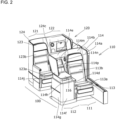
Figure 2] FIG. 2 is a perspective view from the front side of the aircraft seat structure according to the invention. - [
Figure 3] FIG. 3 is a top view of the aircraft seat structure according to the present invention. - [
Figure 4] FIG. 4 is a perspective view from the rear side of the aircraft seat structure according to the present invention. - [
Figure 5] FIG. 5 is a side view of the aircraft seat structure according to the present invention as viewed from the right side in the traveling direction. - [
Figure 6] FIG. 6 is a side view illustrating the aircraft seat structure according to the first embodiment as seen from the side. - [
Figure 7] FIG. 7 is a side view illustrating the aircraft seat structure according to the first embodiment as seen from the side. - [
Figure 8] FIG. 8 is a schematic view of a winding mechanism used in the present embodiment. -
-
FIG. 1 is a perspective view from the rear side of the aircraft seat structure according to the present invention, and illustrates an upright state.FIG. 2 is a perspective view from the front side of the aircraft seat structure according to the present invention. -
FIG. 3 is a top view of the aircraft seat structure according to the present invention. -
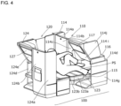
FIG. 4 is a perspective view from the rear side of the aircraft seat structure according to the present invention, and illustrates a reclining state. - Here, the
aircraft seat structure 100 will be described as a single unit having afirst seat unit 110 and asecond seat unit 120 coupled to the rear side of thefirst seat unit 110. - The
first seat unit 110 includes afirst seat region 111 including aseat 113, and afirst side region 112 provided laterally adjacent to theseat 113. Theseat 113 can be changed in form between an upright state in which the backrest is upright and a reclining state in which the backrest is tilted to approach a horizontal state. - Similarly, the
second seat unit 120 includes asecond seat region 121 including aseat 123, and afirst side region 122 provided laterally adjacent to theseat 122. Theseat 123 can be changed in form between an upright state in which the backrest is upright and a reclining state in which the backrest is tilted to approach a horizontal state. - Further, as illustrated in
FIG. 2 andFIG. 3 , thefirst side region 112 of thefirst seat unit 110 is provided on the right side of theseat 113 along a direction that intersects the traveling direction of the aircraft, and thesecond side region 122 of thesecond seat unit 120 is provided on the left side of theseat 123 along a direction that intersects the traveling direction of the aircraft. - At this time, it is preferable that the
first seat unit 110 and thesecond seat unit 120 be formed such that their respective seat areas and side areas have the same size. In this way, theseats - The
seat 113 includes aseating portion 113a and abackrest 113b that is tiltable with respect to theseating portion 113a. Similarly, theseat 123 includes aseating portion 123a and abackrest 123b that is tiltable with respect to theseating portion 123a. - A
partition wall 114 integrally formed of a composite material is disposed between thefirst seat unit 110 and thesecond seat unit 120. Thepartition wall 114 includes, in a continuously joined fashion, a seatside surface portion 114a that surrounds the side portion of theseat 113, a seatback surface portion 114b that covers the back surface of theseat 113, anintermediate wall 114c formed between theseat 113 and thefirst side region 112, ahousing portion 114d forming thefirst side region 112, and amonitor mounting wall 114e (FIG. 2 ) extending from thehousing portion 114d to thesecond seat unit 120 side. - The interior of the
housing portion 114d is separated from thefirst seat unit 110 by theintermediate wall 114c, afront panel 114f, aside panel 114g, and atop panel 114h. However, thesecond seat unit 120 side of thehousing portion 114d is open, and the internal space of thehousing portion 114d can be accessed from here. In other words, thehousing portion 114d serves as a partition, and thefirst side region 112 is joined in a state in which a part of thesecond seat region 121 is inserted. A sound absorbing material or the like may be attached to the inner wall of thehousing portion 114d. - Inside the
housing portion 114d, afoot rest portion 115 supported at both ends by theintermediate wall 114c and theside panel 114g is disposed. The lower portion of thefoot rest portion 115 can be used as a space for placing small baggage or the like. - A side table 116 that can be used by a passenger seated on the
seat 113 is disposed on thetop panel 114h of thehousing portion 114d (FIG. 2 ). - The
monitor mounting wall 114e extends at an incline from the upper end edge of thehousing portion 114d on thesecond seat unit 120 side toward thesecond seat unit 120 side. Since themonitor mounting wall 114e is inclined toward thesecond seat unit 120, passengers using thefirst seat unit 110 do not feel feelings of oppressiveness. The back surface (the lower surface) of themonitor mounting wall 114e is aninclined surface 114i tilted so as to fall toward thesecond seat unit 120 side. Theinclined surface 114i is connected to the lower surface of thetop panel 114h of thehousing portion 114d. Apartition plate 114j is supported on the side edge of themonitor mounting wall 114e and extends in the same direction as theside panel 114g of thehousing portion 114d. The inclination angle of theinclined surface 114i is preferably within 45 degrees with respect to the horizontal plane. - In the vicinity of the upper end of the
inclined surface 114i, an upper edge of amonitor 117 with its screen facing thesecond seat unit 120 side is attached via a hinge (not shown in the figure). By attaching themonitor 117 in the vicinity of the upper end of theinclined surface 114i, the distance between the passenger using thesecond seat unit 120 and the monitor screen can be reduced, such that high-definition images or videos can be viewed even on a small screen. Further, themonitor 117 can be manually or electrically displaced between the erect position illustrated inFIG. 1 and the tilted position illustrated inFIG. 4 . In the tilted position, themonitor 117 extends in a direction along theinclined surface 114i. Theinclined surface 114i may be provided with a rectangularconcave portion 114k into which the electronic component accommodating portion on the back surface of themonitor 117 fits when themonitor 117 is tilted (FIG. 1 ). In this way, the difference in height between the screen of themonitor 117 and theinclined surface 114i can be reduced. - When the
monitor 117 is tilted to the erect position as illustrated inFIG. 1 , a triangular, tubular space is formed between themonitor 117 and theinclined surface 114i. For this reason, in the case that a passenger's head falls forward and hits themonitor 117 as a result of the aircraft shaking, for example, themonitor 117 can retract with a light force, thereby enhancing safety. It should be noted that, although not illustrated in the figures, when themonitor 117 in the erect position is pushed by a force equal to or greater than a threshold value from thesecond seat unit 120 side, themonitor 117 may be unlocked and themonitor 117 may automatically retract to the position illustrated inFIG. 4 by the force of a spring. - In
FIG. 2 , apocket 114m for accommodating headphones or the like, a light 114n for thefirst seat unit 110, and anaccommodation portion 114p for accommodating a remote controller for in-flight entertainment or the like is formed on the front surface of themonitor mounting wall 114e. - On the other hand, a
partition wall 124 integrally formed of composite materials is disposed between thesecond seat unit 120 and the rear side seat unit thereof (not illustrated in the Figure). Thepartition wall 124, which has a shape that is a mirror image of thepartition wall 114, includes a seatside surface portion 124a that surrounds the side portion of theseat 123, a seat backsurface portion 124b that surrounds the back surface of theseat 123, anintermediate wall 124c (FIG. 2 ) formed between theseat 123 and thesecond side region 122, ahousing portion 124d forming thesecond side region 122, and amonitor mounting wall 124e extending rearward from thehousing portion 124d. It should be noted that a redundant description of configurations similar to that of thefirst seat unit 110 will be omitted. - The
housing portion 124d has a similar configuration to thehousing portion 114d, and themonitor mounting wall 124e has a similar configuration to themonitor mounting wall 114e. Amonitor 127 is tiltably mounted on themonitor mounting wall 124e. A passenger control unit PCU equipped with an on/off switch for themonitor 117 viewed by the passenger sitting on theseat 123, a switch for selecting a channel, a knob for changing a sound volume, a switch for performing tilting in the case that the monitor is configured to be tilted by electric power, a switch for changing theseat 123 to an upright state or a reclining state, and the like is disposed below the side table 126 so as to face the seat 123 (FIG. 5 ). It should be noted that a similar passenger control unit is also arranged for thefirst seat unit 110. - The
seat 123 of thesecond seat unit 120 can be form changed between an upright state and a reclining state by a driving mechanism (not illustrated in the figure) by operating the passenger control unit PCU. Such a driving mechanism can use, for example, the technique ofJapanese Translation of PCT International Application Publication No. 2010-520117 - More specifically, in the case that the
seat 123 is in the upright state, thebackrest 123b is angled at approximately 100 degrees with respect to theseating portion 123a. The passenger seated on theseat 123 in this state can see the screen of themonitor 117 while being supported by thebackrest 123b. In addition, the passenger may also place their feet on thefoot rest portion 115. - At this time, by displacing the
monitor 117 with the hand of the passenger or by operating the passenger control unit PCU and setting themonitor 117 to an erect position as illustrated inFIG. 1 , since the face of the passenger faces themonitor 117, the images displayed on themonitor 117 can be naturally viewed. - On the other hand, in the case of changing the
seat 123 to the reclining state, driven by the driving mechanism not illustrated in the figure, theseating portion 123a advances toward thehousing portion 114d while thebackrest 123b approaches the horizontal and enters a state of being close to or in contact with thefoot rest portion 115 as illustrated inFIG. 4 . In the reclining state, thebackrest 123b, theseating portion 123a, and thefoot rest portion 115 are in a substantially flat state. - At this time, the passenger PS can lie on the
seat 123 that has been set to the reclining state, and themonitor 117 can be displaced to a position parallel to theinclined surface 114i as illustrated inFIG. 4 by the hand of the passenger or by operation of the passenger control unit PCU. In this way, even when the passenger PS is lying down, since the face of the passenger PS faces themonitor 117, the images displayed on themonitor 117 can be naturally viewed. - In addition, since a large space is formed below the
monitor 117 and theinclined surface 114i in the tilted position, the passenger PS can take a relaxed posture such as crossing their legs or curling their body and tilting their head forward without being obstructed by themonitor 117, thereby achieving a comfortable flight. -
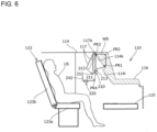
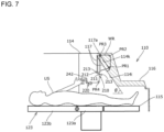
FIG. 6 andFIG. 7 are side views illustrating the aircraft seat structure according to the first embodiment as seen from the side.FIG. 6 illustrates theseat 123 of the second seat region in the upright state.FIG. 7 illustrates theseat 123 of the second seat region in the reclining state. It should be noted that the same reference numerals are assigned to the same configurations as those of the above-described embodiment, and a repetitive description thereof is omitted. - In the present embodiment, the
monitor 117 is rotatably attached to the upper end of theinclined surface 114i of thefirst seat unit 110 via arotation shaft 117a. It is assumed that themonitor 117 is constantly urged clockwise about therotation shaft 117a inFIG. 6 andFIG. 7 by a spring (not illustrated in the figure) having a weaker urging force than a spiral spring 234 (to be described later). Near the lower end of themonitor 117, alocking device 210 is attached to thepartition wall 114. - The
locking device 210 includes aswing shaft 211 that extends in a direction perpendicular to the paper surface and can swing with respect to thepartition wall 114, aswing plate 212 that extends in the radial direction from theswing shaft 211, and a lockingportion 213 protruding upward from both ends of theswing plate 212. - The end of the wire WR is connected to the lower end of the back surface of the
monitor 117. The wire WR is connected to a windingmechanism 220 via pulleys PR1, PR2, PR3, and PR4 that are rotatably attached to thepartition wall 114. As described above, since themonitor 117 is biased clockwise by a spring (not illustrated in the figure), if the tension of the wire WR is not applied, themonitor 117 will tilt to the tilted end illustrated by the dotted line inFIG. 6 or the erect position illustrated by the solid line inFIG. 7 . -
FIG. 8 is a schematic view of the windingmechanism 220. InFIG. 8 , the windingmechanism 220 that constitutes the driving mechanism includes arotating portion 230 and alever portion 240. The rotatingportion 230 includes a fixedshaft 231 which is fixed to thepartition wall 114, atoothed disk 232 which rotates about the fixedshaft 231, adrum 233 which is coaxially connected to thetoothed disk 232, and aspiral spring 234 that connects the fixedshaft 231 and thedrum 233. - On the outer periphery of the
toothed disk 232, a plurality ofteeth 235 having a shortinclined surface 235a and a long inclinedsurface 235b are formed adjacent to each other in the circumferential direction. The shortinclined surface 235a extends substantially along the radial direction of thetoothed disk 232. The end of the wire WR is connected to the outer circumference of thedrum 233, and the wire WR is wound around the outer circumference of thedrum 233. - The
lever portion 240 includes alever shaft 241 fixed to thepartition wall 114, and a lever (an operation unit) 242 that can swing around thelever shaft 241. Thelever 242 is formed with aclaw portion 243 protruding toward thetoothed disk 232 and aconvex portion 244 protruding downward. Theclaw portion 243 can be engaged with the shortinclined surface 235a of theteeth 235 of thetoothed disk 232. Aspring 245 is arranged between theconvex portion 244 and a portion of thepartition wall 114, and theconvex portion 244 is pressed toward acontact locking portion 114s by the urging force of thespring 245. Thetoothed disk 232 and thedrum 233 are urged counterclockwise inFIG. 8 by thespiral spring 234, and in a free state, theclaw portion 243 of thelever 242 comes into contact with the shortinclined surface 235a of theteeth 235 of thetoothed disk 232, such that thetoothed disk 232 is prevented from rotating. - Next, the operation of the present embodiment will be described. Here, with regard to the angle of the
monitor 117, when the axis of themonitor 117 is in the vertical direction (here, the direction perpendicular to the floor of the aircraft) as illustrated by the solid lines inFIG. 6 andFIG. 7 , the monitor inclination angle is considered to be zero (the erect position), in the case that themonitor 117 is tilted toward a user US who views the screen of themonitor 117, the monitor inclination angle is considered to be in a negative angle range, and in the case that themonitor 117 is tilted away from the user US, the monitor inclination angle is considered to be in a positive angle range. - First, as illustrated in
FIG. 6 , in the case that theseat 123 is in the upright state, theswing shaft 211 of thelocking device 210 swings counterclockwise so that the lockingportion 213 comes into contact with the back surface of themonitor 117, which is in the erect position. This is referred to as the upright position. When theseat 123 is moved to the upright state, thelocking device 210 may be swung to the upright position by an actuator or the like connected to theseat 123, or alternatively swung to the upright position in response to the movement of theseat 123 by the link mechanism. - In such a state, when the user US grasps the
monitor 117 with their own hand and pulls it forward, themonitor 117 is tilted around therotation shaft 117a, whereby themonitor 117 can be displaced to the most visible position. At this time, by setting the monitor inclination angle at which themonitor 117 can be tilted within the negative angle range (for example, 0 to -30 degrees), optimum viewing can be achieved in accordance with the body type of the user US. It should be noted that themonitor 117 abuts a stopper (not illustrated in the figure) at the maximum position in the negative angle range to prevent further tilting. - When the
monitor 117 is swung forward, the wire WR is pulled and thedrum 233 of the windingmechanism 220 illustrated inFIG. 8 rotates clockwise. At this time, thetoothed disk 232 rotates clockwise together with thedrum 233 against the urging force of thespiral spring 234, and theclaw portion 243 of thelever 242 slides along the long inclinedsurface 235b of theteeth 235. When sliding, theclaw portion 243 is pushed by the longinclined surface 235b, and each time theclaw portion 243 passes by one long inclinedsurface 235b, thelever 242 tilts as illustrated by the dashed line inFIG. 8 while theconvex portion 244 compresses thespring 245, allowing thedrum 233 to rotate. As a result, the wire WR can be freely pulled out, such that the operation of the user who pulls out themonitor 117 forward is not hindered. Further, when the user US releases their hand, thetoothed disk 232 rotates counterclockwise due to the urging force of thespiral spring 234, but theclaw portion 243 engages with any of the shortinclined surfaces 235a, whereby the rotation of thedrum 233 is locked so that themonitor 117 stays in that position. - On the other hand, in the case that it is desired to return the
monitor 117 to the original position, the user US tilts thelever 242 from the solid line position to the dashed line position against the urging force of thespring 245. As thelever 242 tilts, theclaw portion 243 of thelever 242 disengages from the shortinclined surface 235a of theteeth 235 of thetoothed disk 232, and the urging force of thespiral spring 234 causes thetoothed disk 232 and thedrum 233 to begin to rotate counterclockwise inFIG. 8 . As a result, the wire WR is pulled, drawing the lower end of themonitor 117 toward theinclined surface 114i, and the inclination angle of themonitor 117 approaches zero. When the user US releases their hand from thelever 242, the urging force of thespring 245 causes thelever 242 to return to its original position, and theclaw portion 243 engages with the shortinclined surface 235a, thereby stopping the rotation of thetoothed disk 232 and thedrum 233, and themonitor 117 remains in that position. When the user US continues to pull thelever 242, the lockingportion 213 of thelocking device 210 eventually hits the back of themonitor 117 to prevent further tilting, and themonitor 117 is engaged in a state where the inclination angle is zero. - It should be noted that the
lever 242 can be tilted by remote control using, for example, an electromagnetic solenoid. For example, at the time of takeoff and landing of the aircraft, in principle, theseat 123 is returned to the upright state in order to ensure safety. At this time, the cabin attendant can operate switches (not illustrated in the figure) to tilt thelevers 242 of each seat all at once. - Next, as illustrated in
FIG. 7 , when theseat 123 is in the reclining state, theswing shaft 211 of thelocking device 210 swings clockwise so that the lockingportion 213 comes into contact with the front surface of themonitor 117 in an erect position. This is referred to as the reclining portion. - When the user US lying on the
seat 123 in the reclining state attempts to view the screen of themonitor 117 that is in the erect position, the user US looks up at the screen, which can often be difficult to see. However, if it is necessary for the user US to take the trouble to get up in order to tilt themonitor 117, this causes a burden on the user US. In the present embodiment, thelever 242 is positioned with the reach of the user US lying on theseat 123. - When the user US tilts the
lever 242, as described above, thetoothed disk 232 is rotated counterclockwise inFIG. 8 by the urging force of thespiral spring 234, the wire WR is pulled, and themonitor 117 can be tilted in a direction in which the inclination angle is in the positive angle range. When the user US releases their hand from thelever 242, the pulling of the wire WR is interrupted, and themonitor 117 remains in that position as described above. As a result, the user US can view the screen of themonitor 117 at a desired monitor inclination angle in the positive angle range. If the user US continues to pull thelever 242, themonitor 117 eventually tilts to a position in which it is accommodated in theconcave portion 114k of theinclined surface 114i. - When the
monitor 117 is accommodated in theconcave portion 114k, further tilting is prevented, and themonitor 117 is locked at a monitor inclination angle which is the maximum value of the positive angle range (here, +35 degrees). - The monitor inclination angle that is the maximum value of the positive angle range is preferably 30 degrees to 45 degrees in order to ensure the visibility of the
monitor 117. In addition, it is preferable that the inclination angle θ of theinclined surface 114i with respect to the floor surface is equal to the maximum value of the monitor inclination angle in order to ensure effective utilization of the space and improvement of design. - Since the user US gets up by themself when returning the
seat 123 to the upright state, themonitor 117 can be reached, and themonitor 117 can be grasped and returned to the erect position. - Although the aircraft seat structure according to the present embodiments has been described above, the present invention is not limited to the specific examples described above, and various modifications can be made within the scope of the appended claims. For example, the
monitor 117 may be tiltable between two positions of an erect position and a tilted position, may be locked at a plurality of tilted positions between the erect position and the tilted position, or alternatively may be configured to be steplessly displaced and locked at an arbitrary position. - 10 Aircraft, 100 Aircraft Seat Structure, 110 First Seat Unit, 120 Second Seat Unit, 111, 121 Seat Region, 112, 122 Side Region, 113, 123 Seat, 114, 124 Partition Wall, Monitor 117,127, 210 Locking Device, 220 Winding Mechanism
Claims (8)
- An aircraft seat structure (100) comprising:a first seat unit (110) having a first seat region (111) in which passengers are able to sit, and a first side region (112) adjacent in a direction perpendicular to a longitudinal direction of the first seat region (111) ; anda second seat unit (120) having a second seat region (121) in which passengers are able to sit, and a second side region (122) adjacent in a direction perpendicular to a longitudinal direction of the second seat region (121) ;wherein:the first side region (112) is provided on one side of the first seat region (111) along a direction that intersects a traveling direction of an aircraft, and the second side region (122) is provided on another side of the second seat region (121) along the direction that intersects the traveling direction of the aircraft,the first side region (112) and the second seat region (121) are joined in a state in which a portion of the second seat region (121) is inserted into the first side region (112),the first side region (112) and the second side region (122) are separated by a partition wall (114, 124),the partition wall (114, 124) has an inclined surface tilted toward the second seat unit (120);a locking device (210) being attached to the partition wall (114, 124), the locking device including a locking portion (213),characterized in that a monitor (117, 127) is tiltably mounted to the inclined surface,a seat (123) of the second seat region (121) can be changed in form between an upright state and a reclining state and the monitor (117, 127) can be displaced between a tilted position corresponding to the upright state and a tilted position corresponding to the reclining state;when the seat (123) of the second seat region (121) is in the upright state, the locking portion (213) of the locking device (210) of the seat (123) of the second seat region (121) is configured to abut a back surface of the monitor (117, 127) ; andthe locking portion (213) of the locking device (210) of the seat (123) of the second seat region (121) is configured to abut a front surface of the monitor (117, 127) when the seat (123) of the second seat region (121) is in the reclining state.
- The aircraft seat structure (100) according to claim 1, wherein:the partition wall (114, 124) has a housing portion that separates the first side region (112) and the second seat region (121) ; andthe inclined surface is a back surface of a mounting wall that extends from the housing portion toward the second seat unit (120).
- The aircraft seat structure (100) according to claim 2, wherein:
a foot rest portion is formed in the housing portion. - The aircraft seat structure (100) according to any one of claims 1 to 3, wherein:when the monitor (117, 127) is displaced to the tilted position corresponding to the upright state, a space is formed between the monitor (117, 127) and the inclined surface; andwhen the monitor (117, 127) is displaced to the tilted position corresponding to the reclining state, the monitor (117, 127) extends in a direction along the inclined surface.
- The aircraft seat structure according to any one of claims 1 to 4, wherein:when the seat (123) of the second seat region (121) is in the upright state, the monitor (117, 127) can be titled in a negative angle range; andwhen the seat (123) of the second seat region (121) is in the reclining state, the monitor (117, 127) can be titled in a positive angle range.
- The aircraft seat structure (100) according to any one of claims 1 to 5, further comprising:
a driving mechanism for tilting the monitor (117, 127) to a predetermined position. - The aircraft seat structure according (100) to claim 6, wherein:
an operation unit of the driving mechanism is arranged at a position accessible to a hand of a user lying on a seat in a reclining state. - The aircraft seat structure (100) according to any one of claims 1 to 7, wherein:
the inclined surface includes a concave portion for housing a portion of the monitor (117, 127).
Applications Claiming Priority (2)
| Application Number | Priority Date | Filing Date | Title |
|---|---|---|---|
| JP2019059826 | 2019-03-27 | ||
| PCT/JP2020/011075 WO2020195945A1 (en) | 2019-03-27 | 2020-03-13 | Aircraft seat structure |
Publications (3)
| Publication Number | Publication Date |
|---|---|
| EP3950504A1 EP3950504A1 (en) | 2022-02-09 |
| EP3950504A4 EP3950504A4 (en) | 2022-11-23 |
| EP3950504B1 true EP3950504B1 (en) | 2024-07-31 |
Family
ID=72611441
Family Applications (1)
| Application Number | Title | Priority Date | Filing Date |
|---|---|---|---|
| EP20779709.3A Active EP3950504B1 (en) | 2019-03-27 | 2020-03-13 | Aircraft seat structure |
Country Status (4)
| Country | Link |
|---|---|
| US (1) | US11731764B2 (en) |
| EP (1) | EP3950504B1 (en) |
| JP (1) | JP6949245B2 (en) |
| WO (1) | WO2020195945A1 (en) |
Families Citing this family (8)
| Publication number | Priority date | Publication date | Assignee | Title |
|---|---|---|---|---|
| GB2586043B (en) * | 2019-07-31 | 2023-05-10 | Safran Seats Gb Ltd | Aircraft passenger seat unit with movable panel |
| DE102020108436A1 (en) * | 2020-03-26 | 2021-09-30 | Recaro Aircraft Seating Gmbh & Co. Kg | Aircraft seating arrangement |
| USD989500S1 (en) * | 2020-09-24 | 2023-06-20 | Panasonic Intellectual Property Management Co., Ltd. | Combined transmissive display and airplane seat unit |
| USD990904S1 (en) * | 2020-09-24 | 2023-07-04 | Panasonic Intellectual Property Management Co., Ltd. | Combined transmissive display and airplane seat unit |
| USD990181S1 (en) * | 2020-09-24 | 2023-06-27 | Panasonic Intellectual Property Management Co., Ltd. | Combined transmissive display and airplane seat unit |
| USD984155S1 (en) * | 2020-09-24 | 2023-04-25 | Panasonic Intellectual Property Management Co., Ltd. | Combined transmissive display and airplane seat unit |
| US20240351689A1 (en) * | 2023-04-24 | 2024-10-24 | B/E Aerospace, Inc. | Passenger seating system |
| DE102023122439A1 (en) * | 2023-08-22 | 2025-02-27 | Recaro Aircraft Seating Gmbh & Co. Kg | aircraft seating system |
Family Cites Families (12)
| Publication number | Priority date | Publication date | Assignee | Title |
|---|---|---|---|---|
| US6227489B1 (en) | 1998-05-15 | 2001-05-08 | Koito Industries, Ltd. | Aircraft seat apparatus |
| RU2255372C2 (en) | 2003-08-26 | 2005-06-27 | Баженов Владимир Александрович | Method for transferring and processing data when performing tournaments in intellectual games between distanced gamers and system for realization of said method |
| JP2008279155A (en) * | 2007-05-14 | 2008-11-20 | Panasonic Corp | Image display device |
| GB2490095B (en) * | 2011-04-01 | 2017-05-10 | Zodiac Seats Uk Ltd | Aircraft seat arrangement including table |
| WO2012140515A1 (en) * | 2011-04-15 | 2012-10-18 | Societe Industrielle Et Commerciale De Materiel Aeronautique | Passenger seating arrangements |
| GB2500258B (en) * | 2012-03-16 | 2019-05-08 | Zodiac Seats Uk Ltd | High density aircraft seat arrangement |
| DE102013011514A1 (en) * | 2013-05-07 | 2014-11-13 | Recaro Aircraft Seating Gmbh & Co. Kg | airplane seat |
| EP3060474B1 (en) * | 2013-10-24 | 2020-07-15 | Safran Seats | Seat unit for a vehicle cabin |
| GB2523309B (en) * | 2014-02-12 | 2015-12-23 | British Airways Plc | Aircraft passenger seating arrangements |
| FR3049578B1 (en) * | 2016-03-31 | 2019-08-16 | Stelia Aerospace | ARMCHAIR SEAT ASSEMBLY AGENCIES IN QUINCONCE |
| JP6389900B2 (en) | 2016-04-01 | 2018-09-12 | 株式会社ジャムコ | Aircraft seat structure |
| EP3873776B1 (en) | 2018-11-02 | 2023-07-05 | Style & Design Group | Passenger seat unit for an aircraft cabin |
-
2020
- 2020-03-13 WO PCT/JP2020/011075 patent/WO2020195945A1/en not_active Ceased
- 2020-03-13 JP JP2020552432A patent/JP6949245B2/en active Active
- 2020-03-13 US US17/440,782 patent/US11731764B2/en active Active
- 2020-03-13 EP EP20779709.3A patent/EP3950504B1/en active Active
Also Published As
| Publication number | Publication date |
|---|---|
| US20220161929A1 (en) | 2022-05-26 |
| EP3950504A1 (en) | 2022-02-09 |
| US11731764B2 (en) | 2023-08-22 |
| WO2020195945A1 (en) | 2020-10-01 |
| EP3950504A4 (en) | 2022-11-23 |
| JPWO2020195945A1 (en) | 2021-04-30 |
| JP6949245B2 (en) | 2021-10-13 |
Similar Documents
| Publication | Publication Date | Title |
|---|---|---|
| EP3950504A1 (en) | Aircraft seat structure | |
| CN1114547C (en) | aircraft seat assembly | |
| US6669141B2 (en) | Aircraft passenger cabin with rotatable passenger seats | |
| JP3990986B2 (en) | Adjustable seat | |
| CN106114870B (en) | Passenger seat component and its many aspects | |
| JP5248325B2 (en) | Aircraft passenger seat | |
| EP2391541B1 (en) | Seating arrangement, seat unit, tray table and seating system | |
| CN105338859B (en) | Passenger seat with descending armrest assembly | |
| US8297554B2 (en) | Arrangement of a first and a second furnishing | |
| EP3277583B1 (en) | Adjustable headrest enabling sideward leaning and seclusion | |
| US20130242523A1 (en) | Deployable in-flight entertainment monitor | |
| AU2012351859A1 (en) | Vehicle seat | |
| CN110198891A (en) | With the seating passengers device that can pack up handrail | |
| EP3395686A1 (en) | Non-intrusive and reclining seating arrangement for an airplane or other means or transportation | |
| US8851568B2 (en) | Retractable passenger seat | |
| US20150314713A1 (en) | Vehicle Seat | |
| EP2900552B1 (en) | Aircraft sideboard | |
| US12552538B2 (en) | Seat assembly | |
| CN114466795B (en) | Non-intrusive fixed monitor shield | |
| US12409938B2 (en) | Seat arrangements, in particular for an aircraft cabin | |
| US20230257121A1 (en) | Suite with improved arrangement, in particular for an aircraft cabin |
Legal Events
| Date | Code | Title | Description |
|---|---|---|---|
| STAA | Information on the status of an ep patent application or granted ep patent |
Free format text: STATUS: THE INTERNATIONAL PUBLICATION HAS BEEN MADE |
|
| PUAI | Public reference made under article 153(3) epc to a published international application that has entered the european phase |
Free format text: ORIGINAL CODE: 0009012 |
|
| STAA | Information on the status of an ep patent application or granted ep patent |
Free format text: STATUS: REQUEST FOR EXAMINATION WAS MADE |
|
| 17P | Request for examination filed |
Effective date: 20210923 |
|
| AK | Designated contracting states |
Kind code of ref document: A1 Designated state(s): AL AT BE BG CH CY CZ DE DK EE ES FI FR GB GR HR HU IE IS IT LI LT LU LV MC MK MT NL NO PL PT RO RS SE SI SK SM TR |
|
| DAV | Request for validation of the european patent (deleted) | ||
| DAX | Request for extension of the european patent (deleted) | ||
| A4 | Supplementary search report drawn up and despatched |
Effective date: 20221021 |
|
| RIC1 | Information provided on ipc code assigned before grant |
Ipc: B64D 11/00 20060101ALI20221017BHEP Ipc: B60N 3/06 20060101ALI20221017BHEP Ipc: B60N 3/00 20060101ALI20221017BHEP Ipc: B60N 2/22 20060101ALI20221017BHEP Ipc: B60N 2/01 20060101ALI20221017BHEP Ipc: B64D 11/06 20060101AFI20221017BHEP |
|
| GRAP | Despatch of communication of intention to grant a patent |
Free format text: ORIGINAL CODE: EPIDOSNIGR1 |
|
| STAA | Information on the status of an ep patent application or granted ep patent |
Free format text: STATUS: GRANT OF PATENT IS INTENDED |
|
| INTG | Intention to grant announced |
Effective date: 20240306 |
|
| GRAS | Grant fee paid |
Free format text: ORIGINAL CODE: EPIDOSNIGR3 |
|
| GRAA | (expected) grant |
Free format text: ORIGINAL CODE: 0009210 |
|
| STAA | Information on the status of an ep patent application or granted ep patent |
Free format text: STATUS: THE PATENT HAS BEEN GRANTED |
|
| P01 | Opt-out of the competence of the unified patent court (upc) registered |
Effective date: 20240524 |
|
| AK | Designated contracting states |
Kind code of ref document: B1 Designated state(s): AL AT BE BG CH CY CZ DE DK EE ES FI FR GB GR HR HU IE IS IT LI LT LU LV MC MK MT NL NO PL PT RO RS SE SI SK SM TR |
|
| REG | Reference to a national code |
Ref country code: CH Ref legal event code: EP Ref country code: GB Ref legal event code: FG4D |
|
| REG | Reference to a national code |
Ref country code: DE Ref legal event code: R096 Ref document number: 602020034936 Country of ref document: DE |
|
| REG | Reference to a national code |
Ref country code: IE Ref legal event code: FG4D |
|
| REG | Reference to a national code |
Ref country code: LT Ref legal event code: MG9D |
|
| REG | Reference to a national code |
Ref country code: NL Ref legal event code: MP Effective date: 20240731 |
|
| PG25 | Lapsed in a contracting state [announced via postgrant information from national office to epo] |
Ref country code: PT Free format text: LAPSE BECAUSE OF FAILURE TO SUBMIT A TRANSLATION OF THE DESCRIPTION OR TO PAY THE FEE WITHIN THE PRESCRIBED TIME-LIMIT Effective date: 20241202 |
|
| REG | Reference to a national code |
Ref country code: AT Ref legal event code: MK05 Ref document number: 1708260 Country of ref document: AT Kind code of ref document: T Effective date: 20240731 |
|
| PG25 | Lapsed in a contracting state [announced via postgrant information from national office to epo] |
Ref country code: PT Free format text: LAPSE BECAUSE OF FAILURE TO SUBMIT A TRANSLATION OF THE DESCRIPTION OR TO PAY THE FEE WITHIN THE PRESCRIBED TIME-LIMIT Effective date: 20241202 |
|
| PG25 | Lapsed in a contracting state [announced via postgrant information from national office to epo] |
Ref country code: NO Free format text: LAPSE BECAUSE OF FAILURE TO SUBMIT A TRANSLATION OF THE DESCRIPTION OR TO PAY THE FEE WITHIN THE PRESCRIBED TIME-LIMIT Effective date: 20241031 |
|
| PG25 | Lapsed in a contracting state [announced via postgrant information from national office to epo] |
Ref country code: FI Free format text: LAPSE BECAUSE OF FAILURE TO SUBMIT A TRANSLATION OF THE DESCRIPTION OR TO PAY THE FEE WITHIN THE PRESCRIBED TIME-LIMIT Effective date: 20240731 Ref country code: NL Free format text: LAPSE BECAUSE OF FAILURE TO SUBMIT A TRANSLATION OF THE DESCRIPTION OR TO PAY THE FEE WITHIN THE PRESCRIBED TIME-LIMIT Effective date: 20240731 Ref country code: PL Free format text: LAPSE BECAUSE OF FAILURE TO SUBMIT A TRANSLATION OF THE DESCRIPTION OR TO PAY THE FEE WITHIN THE PRESCRIBED TIME-LIMIT Effective date: 20240731 Ref country code: GR Free format text: LAPSE BECAUSE OF FAILURE TO SUBMIT A TRANSLATION OF THE DESCRIPTION OR TO PAY THE FEE WITHIN THE PRESCRIBED TIME-LIMIT Effective date: 20241101 |
|
| PG25 | Lapsed in a contracting state [announced via postgrant information from national office to epo] |
Ref country code: BG Free format text: LAPSE BECAUSE OF FAILURE TO SUBMIT A TRANSLATION OF THE DESCRIPTION OR TO PAY THE FEE WITHIN THE PRESCRIBED TIME-LIMIT Effective date: 20240731 |
|
| PG25 | Lapsed in a contracting state [announced via postgrant information from national office to epo] |
Ref country code: LV Free format text: LAPSE BECAUSE OF FAILURE TO SUBMIT A TRANSLATION OF THE DESCRIPTION OR TO PAY THE FEE WITHIN THE PRESCRIBED TIME-LIMIT Effective date: 20240731 |
|
| PG25 | Lapsed in a contracting state [announced via postgrant information from national office to epo] |
Ref country code: AT Free format text: LAPSE BECAUSE OF FAILURE TO SUBMIT A TRANSLATION OF THE DESCRIPTION OR TO PAY THE FEE WITHIN THE PRESCRIBED TIME-LIMIT Effective date: 20240731 Ref country code: IS Free format text: LAPSE BECAUSE OF FAILURE TO SUBMIT A TRANSLATION OF THE DESCRIPTION OR TO PAY THE FEE WITHIN THE PRESCRIBED TIME-LIMIT Effective date: 20241130 |
|
| PG25 | Lapsed in a contracting state [announced via postgrant information from national office to epo] |
Ref country code: HR Free format text: LAPSE BECAUSE OF FAILURE TO SUBMIT A TRANSLATION OF THE DESCRIPTION OR TO PAY THE FEE WITHIN THE PRESCRIBED TIME-LIMIT Effective date: 20240731 |
|
| PG25 | Lapsed in a contracting state [announced via postgrant information from national office to epo] |
Ref country code: RS Free format text: LAPSE BECAUSE OF FAILURE TO SUBMIT A TRANSLATION OF THE DESCRIPTION OR TO PAY THE FEE WITHIN THE PRESCRIBED TIME-LIMIT Effective date: 20241031 Ref country code: ES Free format text: LAPSE BECAUSE OF FAILURE TO SUBMIT A TRANSLATION OF THE DESCRIPTION OR TO PAY THE FEE WITHIN THE PRESCRIBED TIME-LIMIT Effective date: 20240731 |
|
| PG25 | Lapsed in a contracting state [announced via postgrant information from national office to epo] |
Ref country code: RS Free format text: LAPSE BECAUSE OF FAILURE TO SUBMIT A TRANSLATION OF THE DESCRIPTION OR TO PAY THE FEE WITHIN THE PRESCRIBED TIME-LIMIT Effective date: 20241031 Ref country code: PL Free format text: LAPSE BECAUSE OF FAILURE TO SUBMIT A TRANSLATION OF THE DESCRIPTION OR TO PAY THE FEE WITHIN THE PRESCRIBED TIME-LIMIT Effective date: 20240731 Ref country code: NO Free format text: LAPSE BECAUSE OF FAILURE TO SUBMIT A TRANSLATION OF THE DESCRIPTION OR TO PAY THE FEE WITHIN THE PRESCRIBED TIME-LIMIT Effective date: 20241031 Ref country code: NL Free format text: LAPSE BECAUSE OF FAILURE TO SUBMIT A TRANSLATION OF THE DESCRIPTION OR TO PAY THE FEE WITHIN THE PRESCRIBED TIME-LIMIT Effective date: 20240731 Ref country code: LV Free format text: LAPSE BECAUSE OF FAILURE TO SUBMIT A TRANSLATION OF THE DESCRIPTION OR TO PAY THE FEE WITHIN THE PRESCRIBED TIME-LIMIT Effective date: 20240731 Ref country code: IS Free format text: LAPSE BECAUSE OF FAILURE TO SUBMIT A TRANSLATION OF THE DESCRIPTION OR TO PAY THE FEE WITHIN THE PRESCRIBED TIME-LIMIT Effective date: 20241130 Ref country code: HR Free format text: LAPSE BECAUSE OF FAILURE TO SUBMIT A TRANSLATION OF THE DESCRIPTION OR TO PAY THE FEE WITHIN THE PRESCRIBED TIME-LIMIT Effective date: 20240731 Ref country code: GR Free format text: LAPSE BECAUSE OF FAILURE TO SUBMIT A TRANSLATION OF THE DESCRIPTION OR TO PAY THE FEE WITHIN THE PRESCRIBED TIME-LIMIT Effective date: 20241101 Ref country code: FI Free format text: LAPSE BECAUSE OF FAILURE TO SUBMIT A TRANSLATION OF THE DESCRIPTION OR TO PAY THE FEE WITHIN THE PRESCRIBED TIME-LIMIT Effective date: 20240731 Ref country code: ES Free format text: LAPSE BECAUSE OF FAILURE TO SUBMIT A TRANSLATION OF THE DESCRIPTION OR TO PAY THE FEE WITHIN THE PRESCRIBED TIME-LIMIT Effective date: 20240731 Ref country code: BG Free format text: LAPSE BECAUSE OF FAILURE TO SUBMIT A TRANSLATION OF THE DESCRIPTION OR TO PAY THE FEE WITHIN THE PRESCRIBED TIME-LIMIT Effective date: 20240731 Ref country code: AT Free format text: LAPSE BECAUSE OF FAILURE TO SUBMIT A TRANSLATION OF THE DESCRIPTION OR TO PAY THE FEE WITHIN THE PRESCRIBED TIME-LIMIT Effective date: 20240731 |
|
| PG25 | Lapsed in a contracting state [announced via postgrant information from national office to epo] |
Ref country code: DK Free format text: LAPSE BECAUSE OF FAILURE TO SUBMIT A TRANSLATION OF THE DESCRIPTION OR TO PAY THE FEE WITHIN THE PRESCRIBED TIME-LIMIT Effective date: 20240731 Ref country code: RO Free format text: LAPSE BECAUSE OF FAILURE TO SUBMIT A TRANSLATION OF THE DESCRIPTION OR TO PAY THE FEE WITHIN THE PRESCRIBED TIME-LIMIT Effective date: 20240731 Ref country code: SM Free format text: LAPSE BECAUSE OF FAILURE TO SUBMIT A TRANSLATION OF THE DESCRIPTION OR TO PAY THE FEE WITHIN THE PRESCRIBED TIME-LIMIT Effective date: 20240731 |
|
| PG25 | Lapsed in a contracting state [announced via postgrant information from national office to epo] |
Ref country code: EE Free format text: LAPSE BECAUSE OF FAILURE TO SUBMIT A TRANSLATION OF THE DESCRIPTION OR TO PAY THE FEE WITHIN THE PRESCRIBED TIME-LIMIT Effective date: 20240731 |
|
| PG25 | Lapsed in a contracting state [announced via postgrant information from national office to epo] |
Ref country code: CZ Free format text: LAPSE BECAUSE OF FAILURE TO SUBMIT A TRANSLATION OF THE DESCRIPTION OR TO PAY THE FEE WITHIN THE PRESCRIBED TIME-LIMIT Effective date: 20240731 |
|
| PG25 | Lapsed in a contracting state [announced via postgrant information from national office to epo] |
Ref country code: SK Free format text: LAPSE BECAUSE OF FAILURE TO SUBMIT A TRANSLATION OF THE DESCRIPTION OR TO PAY THE FEE WITHIN THE PRESCRIBED TIME-LIMIT Effective date: 20240731 Ref country code: IT Free format text: LAPSE BECAUSE OF FAILURE TO SUBMIT A TRANSLATION OF THE DESCRIPTION OR TO PAY THE FEE WITHIN THE PRESCRIBED TIME-LIMIT Effective date: 20240731 |
|
| REG | Reference to a national code |
Ref country code: DE Ref legal event code: R097 Ref document number: 602020034936 Country of ref document: DE |
|
| PLBE | No opposition filed within time limit |
Free format text: ORIGINAL CODE: 0009261 |
|
| STAA | Information on the status of an ep patent application or granted ep patent |
Free format text: STATUS: NO OPPOSITION FILED WITHIN TIME LIMIT |
|
| 26N | No opposition filed |
Effective date: 20250501 |
|
| PG25 | Lapsed in a contracting state [announced via postgrant information from national office to epo] |
Ref country code: SE Free format text: LAPSE BECAUSE OF FAILURE TO SUBMIT A TRANSLATION OF THE DESCRIPTION OR TO PAY THE FEE WITHIN THE PRESCRIBED TIME-LIMIT Effective date: 20240731 |
|
| PG25 | Lapsed in a contracting state [announced via postgrant information from national office to epo] |
Ref country code: MC Free format text: LAPSE BECAUSE OF FAILURE TO SUBMIT A TRANSLATION OF THE DESCRIPTION OR TO PAY THE FEE WITHIN THE PRESCRIBED TIME-LIMIT Effective date: 20240731 |
|
| REG | Reference to a national code |
Ref country code: CH Ref legal event code: H13 Free format text: ST27 STATUS EVENT CODE: U-0-0-H10-H13 (AS PROVIDED BY THE NATIONAL OFFICE) Effective date: 20251024 |
|
| PG25 | Lapsed in a contracting state [announced via postgrant information from national office to epo] |
Ref country code: LU Free format text: LAPSE BECAUSE OF NON-PAYMENT OF DUE FEES Effective date: 20250313 |
|
| REG | Reference to a national code |
Ref country code: BE Ref legal event code: MM Effective date: 20250331 |
|
| PG25 | Lapsed in a contracting state [announced via postgrant information from national office to epo] |
Ref country code: BE Free format text: LAPSE BECAUSE OF NON-PAYMENT OF DUE FEES Effective date: 20250331 |
|
| PG25 | Lapsed in a contracting state [announced via postgrant information from national office to epo] |
Ref country code: CH Free format text: LAPSE BECAUSE OF NON-PAYMENT OF DUE FEES Effective date: 20250331 |
|
| PG25 | Lapsed in a contracting state [announced via postgrant information from national office to epo] |
Ref country code: IE Free format text: LAPSE BECAUSE OF NON-PAYMENT OF DUE FEES Effective date: 20250313 |
|
| PGFP | Annual fee paid to national office [announced via postgrant information from national office to epo] |
Ref country code: GB Payment date: 20260202 Year of fee payment: 7 |
|
| PGFP | Annual fee paid to national office [announced via postgrant information from national office to epo] |
Ref country code: DE Payment date: 20260128 Year of fee payment: 7 |
|
| PGFP | Annual fee paid to national office [announced via postgrant information from national office to epo] |
Ref country code: FR Payment date: 20260209 Year of fee payment: 7 |