EP3950393A2 - Vehicle door coupling device - Google Patents
Vehicle door coupling device Download PDFInfo
- Publication number
- EP3950393A2 EP3950393A2 EP20784465.5A EP20784465A EP3950393A2 EP 3950393 A2 EP3950393 A2 EP 3950393A2 EP 20784465 A EP20784465 A EP 20784465A EP 3950393 A2 EP3950393 A2 EP 3950393A2
- Authority
- EP
- European Patent Office
- Prior art keywords
- shaft
- groove portion
- vehicle door
- coupling device
- hole
- Prior art date
- Legal status (The legal status is an assumption and is not a legal conclusion. Google has not performed a legal analysis and makes no representation as to the accuracy of the status listed.)
- Granted
Links
Images




Classifications
-
- B—PERFORMING OPERATIONS; TRANSPORTING
- B60—VEHICLES IN GENERAL
- B60J—WINDOWS, WINDSCREENS, NON-FIXED ROOFS, DOORS, OR SIMILAR DEVICES FOR VEHICLES; REMOVABLE EXTERNAL PROTECTIVE COVERINGS SPECIALLY ADAPTED FOR VEHICLES
- B60J5/00—Doors
- B60J5/04—Doors arranged at the vehicle sides
- B60J5/0468—Fixation or mounting means specific for door components
-
- B—PERFORMING OPERATIONS; TRANSPORTING
- B60—VEHICLES IN GENERAL
- B60J—WINDOWS, WINDSCREENS, NON-FIXED ROOFS, DOORS, OR SIMILAR DEVICES FOR VEHICLES; REMOVABLE EXTERNAL PROTECTIVE COVERINGS SPECIALLY ADAPTED FOR VEHICLES
- B60J5/00—Doors
- B60J5/04—Doors arranged at the vehicle sides
- B60J5/0412—Lower door structure
- B60J5/0413—Inner panel, e.g. characterised by carrying components
-
- B—PERFORMING OPERATIONS; TRANSPORTING
- B60—VEHICLES IN GENERAL
- B60J—WINDOWS, WINDSCREENS, NON-FIXED ROOFS, DOORS, OR SIMILAR DEVICES FOR VEHICLES; REMOVABLE EXTERNAL PROTECTIVE COVERINGS SPECIALLY ADAPTED FOR VEHICLES
- B60J5/00—Doors
- B60J5/04—Doors arranged at the vehicle sides
- B60J5/0412—Lower door structure
- B60J5/0416—Assembly panels to be installed in doors as a module with components, e.g. lock or window lifter, attached thereto
-
- F—MECHANICAL ENGINEERING; LIGHTING; HEATING; WEAPONS; BLASTING
- F16—ENGINEERING ELEMENTS AND UNITS; GENERAL MEASURES FOR PRODUCING AND MAINTAINING EFFECTIVE FUNCTIONING OF MACHINES OR INSTALLATIONS; THERMAL INSULATION IN GENERAL
- F16B—DEVICES FOR FASTENING OR SECURING CONSTRUCTIONAL ELEMENTS OR MACHINE PARTS TOGETHER, e.g. NAILS, BOLTS, CIRCLIPS, CLAMPS, CLIPS OR WEDGES; JOINTS OR JOINTING
- F16B21/00—Means for preventing relative axial movement of a pin, spigot, shaft or the like and a member surrounding it; Stud-and-socket releasable fastenings
- F16B21/02—Releasable fastening devices locking by rotation
-
- B—PERFORMING OPERATIONS; TRANSPORTING
- B60—VEHICLES IN GENERAL
- B60Y—INDEXING SCHEME RELATING TO ASPECTS CROSS-CUTTING VEHICLE TECHNOLOGY
- B60Y2304/00—Optimising design; Manufacturing; Testing
- B60Y2304/07—Facilitating assembling or mounting
Definitions
- the present disclosure relates to a vehicle door coupling device, and more particularly, to a vehicle door coupling device for mechanically coupling first and second members of an automobile door to each other in a stable and airtight manner.
- doors are also assembled by collecting components such as a door window regulator, a door latch, and a door inside handle into a modular panel, and then coupling the modular panel to a door inner panel.
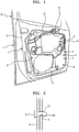
- a door module of the related art is assembled as follows: a door panel 1 of a door D is assembled by joining together both lateral sides and lower ends of a door outer panel and a door inner panel 2 with a cavity being formed therein; a regulator motor 5 of a door window regulator 4 is coupled to the outer surface of a door modular panel 3; a regulator channel (not shown) is coupled to the inner surface of the door modular panel 3; a door inside handle 6 is coupled to the upper outer surface of the modular panel 3; an end of a cable 6' is connected to the door inside handle 6; the other end of the cable 6' is laterally guided and connected to a door latch 7; other necessary cables are installed; the regulator channel and the door latch 7 are inserted into the cavity formed in the door panel 1 while moving the modular panel 3 close to the door inner panel 2; and the door modular panel 3 is attached to the door inner panel 2 by using bolts 8 at at least 4 positions.
- the modular panel 3 when attaching the modular panel 3 to the door inner panel 2 with the bolts 8 as described above, the modular panel 3 is attached to the door inner panel 2 while moving the door panel 1 and maintaining the door panel 1 at a vertical posture using a jig, and thus, a temporary assembling means is used to quickly align the bolts 8 with fastening holes.
- the temporary assembly means is to fix support pins 9 and 9' to both sides of the door modular panel 3, form support holes 10 in the door inner panel 2 at positions corresponding to the support pins 9 and 9', insert the bolts 8 into the support holes 10, and fasten the bolts 8.
- the present disclosure is provided to solve the above-mentioned problems, and more particularly, the technical objective of the present disclosure is to provide a vehicle door coupling device for easily coupling a modular panel and a door inner panel to each other in a shorter work time while guaranteeing airtightness.
- the present disclosure provides a vehicle door coupling device for mechanically coupling together a first member having a first hole inside which an engaging protrusion is provided and a second member having a second hole at a position corresponding to the first hole, the vehicle door coupling device including:
- the position maintaining protrusion may be provided on a portion through which the vertical groove portion and the horizontal groove portion are connected to each other.
- a rotation-suppressing protrusion may be provided in the horizontal groove portion to suppress rotation of the shaft such that unless a force equal to or greater than a given value is applied to the shaft, rotation of the shaft along the horizontal groove portion may be suppressed.
- the stopper of the shaft may have a rear side facing the first member, and a sealing material may be provided on the rear side to guarantee watertightness when the stopper is brought into contact with the first member.
- an anti-loosening structure may be provided on the stopper of the shaft to prevent loosening when the shaft is rotated to the final coupling position.
- the vehicle door coupling device of the present disclosure is configured to be easily fitted into and fixed to a door inner panel in a state in which the vehicle door coupling device is temporarily fitted into a door modular panel, and thus the door modular panel and the door inner panel may be easily coupled to each other using the vehicle door coupling device.
- the crossbar of the vehicle door coupling device partially protrudes from the rear side of the modular panel, and thus, the crossbar does not act as a significant obstacle when the modular panel is attached to the door indoor panel.
- the position maintaining protrusion is provided between the vertical groove portion and the horizontal groove portion of the shaft, and thus, relative rotation of the shaft may be prevented until the shaft is fully inserted.
- the anti-loosening structure is provided to prevent loosening in the final coupling position, and thus, coupling may be securely maintained.
- the sealing material is provided on a side of the stopper which faces the door modular panel, and thus, watertightness may be guaranteed.
- a vehicle door coupling device 100 of the present disclosure is for mechanically coupling together a first member 500 having a first hole 501 and a second member 600 having a second hole 601 at a position corresponding to the first hole 501.
- the first member 500 having the first hole 501 corresponds to a door modular panel.
- Electric components necessary for a door of an automobile are modularized and installed on the door modular panel, and for example, components such as a window regulator and a speaker may be installed on the door modular panel. After given electric components are installed on the door modular panel, the door modular panel is attached to a door inner panel.
- the first hole 501 is formed in the first member 500 such that a shaft 200 may be inserted into the first member 500.
- the first hole 501 has a long hole shape, and an engaging protrusion 502 is provided on the inner surface of the first hole 501.
- the engaging protrusion 502 is fitted into a vertical groove and a horizontal groove of the shaft 200 and protrudes from a rear side (based on FIG. 5 ) of the first member 500. Specifically, the engaging protrusion 502 protrudes toward the inside of the first hole 501.
- An anti-loosening groove 503 is provided in a peripheral region of the first hole 501, and an anti-loosening structure 320 provided on the stopper 300 of the shaft 200 may be fitted and trapped in the anti-loosening groove 503.
- the anti-loosening groove 503 is provided in the periphery region of the first hole 501 in an upper side (based on FIG. 5 ) of the first member 500.
- the second member 600 corresponds to a door inner panel, and the second hole 601 is formed in the second member 600 at a position corresponding to the first hole 501 of the first member 500.
- the second hole 601 has a long hole shape substantially corresponding to a crossbar 400.
- the vehicle door coupling device 100 includes the shaft 200, the stopper 300, and the crossbar 400.
- the shaft 200 has a vertically extending pillar shape such that the shaft 200 may be rotatably fitted into the first hole 501 of the first member 500 and the second hole 601 of the second member 600 and may rotatably pass therethrough.
- the stopper 300 is provided on the upper end of the shaft 200, and the crossbar 400 is formed on the lower end of the shaft 200. (The terms “upper end” and “lower end” are given based on FIG. 4 for ease of illustration.)
- a position maintaining structure 210 is provided on the shaft 200. Owing to the position maintaining structure 210, the shaft 200 may be temporarily coupled to the first member 500 in a vertically movable manner without being separated from the first member 500 in a temporary coupling position (the position shown in FIGS. 4 to 12 ), and the state in which a rear side of the crossbar 400 partially protrudes from the second member 600 may be maintained in the temporary coupling position.
- the position maintaining structure 210 includes: a vertical groove portion 211 which is provided in an outer side of the shaft 200 and vertically extends toward an end of the shaft 200 from the other end of the shaft 200 to receive the engaging protrusion 502 therein and guide the engaging protrusion 502; and a horizontal groove portion 212 which horizontally extends from an end portion of the vertical groove portion 211 to allow rotation of the shaft 200, wherein the vertical groove portion 211 is provided with a position maintaining protrusion 213 which prevents the engaging protrusion 502 of the first hole 501 from entering the horizontal groove portion 212 in the temporary coupling position.
- the positioning protrusion 213 may be provided on a portion through which the vertical groove portion 211 and the horizontal groove portion 212 are connected to each other.
- a separation-preventing protrusion 214 is provided on an upper entrance of the vertical groove portion 211, and thus, the engaging protrusion 502 inserted into the vertical groove portion 211 is prevented from being separated from the vertical groove portion 211 by the separation-preventing protrusion 214.
- the engaging protrusion 502 allows upward or downward movement of the shaft 200 in the temporary coupling position while the engaging protrusion 502 moves upward or downward between the separation-preventing protrusion 214 and the position maintaining protrusion 213.
- the engaging protrusion 502 of the first member 500 is inserted into the vertical groove portion 211 while being moved over the separation-preventing protrusion 214.
- the vertical groove portion 211 prevents the engaging protrusion 502 from moving left and right, thereby preventing the shaft 200 from rotating relative to the first member 500.
- the vertical groove portion 211 has a function of guiding the movement of the engaging protrusion 502 .
- the engaging protrusion 502 having entered the vertical groove portion 211 may move up to the position maintaining protrusion 213, and in the temporary coupling position, the engaging protrusion 502 may move between the separation-preventing protrusion 214 and the position maintaining protrusion 213. Therefore, the shaft 200 may be vertically moved by a predetermined distance in the temporary coupling position. Therefore, when a worker puts the second member 600 on the rear side of the first member 500 in the temporary coupling position, interference caused by the crossbar 400 of the shaft 200 may be minimized.
- the crossbar 400 of the shaft 200 is configured to be freely moved in an axial direction by a distance of about 3 mm to about 6.5 mm from the rear side of the first member 500 in the temporary coupling position, and thus, the crossbar 400 of the shaft 200 may minimally obstruct the movement of the first member 500 to the second member 600.
- the horizontal groove portion 212 is provided with a rotation-suppressing protrusion 215 for suppressing the rotation of the shaft 200, and thus, the rotation of the shaft 200 is prevented unless a force equal to or greater than a given value is applied to the shaft 200 after the engaging protrusion 502 enters the horizontal groove portion 212.
- the engaging protrusion 502 of which left and right rotation in the vertical groove portion 211 is suppressed, is allowed to rotate immediately after the engaging protrusion 502 is vertically moved downward into the horizontal groove portion 212, the second member 600 may be fixed to the first member 500 due to an unintended rotation of the shaft 200, and thus, the rotation-suppressing protrusion 215 is provided to prevent this. Until a sufficient amount of force for moving over the rotation-suppressing protrusion 215 is applied, the rotation of the shaft 200 is suppressed.
- the stopper 300 which is provided on a side of the shaft 200 for supporting the first member 500, is located on an upper side of the shaft 200.
- the stopper 300 has a disk shape and is configured such that the lower surface of the stopper 300 presses the upper surface of the first member 500 in the final coupling position while making contact with the upper surface of the first member 500.
- the stopper 300 supports the first member 500.
- the stopper 300 has a rear side which faces the first member 500, and a sealing material 301 is provided on the rear side of the stopper 300 to guarantee watertightness when the stopper 300 makes contact with the first member 500.
- the sealing material 310 may be a rubber material having a ring shape and configured to provide watertight sealing along the periphery of the first hole 501 of the first member 500.
- the anti-loosening structure 320 is provided on the stopper 300 to prevent the shaft 200 from loosening after being rotated to the final coupling position.
- the anti-loosening structure 320 is a protrusion protruding from the rear side of the stopper 300 and configured to be fitted into the anti-loosening groove 503 of the first member 500.
- the anti-loosening structure 320 is inserted into the anti-loosening groove 503 of the first member 500, thereby fixing the shaft 200 in the final coupling position.
- the crossbar 400 is provided on the other side of the shaft 200, and when the shaft 200 is rotated to the final coupling position, the crossbar 400 supports the second member 600 and fixes the second member 600 to the first member 500.
- the crossbar 400 is located on the lower end of the shaft 200 and generally has a horizontally extending bar shape.
- An inclined surface 410 is formed on an upper surface of the crossbar 400, and when the shaft 200 is rotated in one direction, the distance between the first member 500 and the second member 600 is reduced owing to the inclined surface 410. That is, the thickness of the crossbar 400 increases along the inclined surface 410 such that when the shaft 200 is rotated, the distance between the first member 500 and the second member 600 may be reduced along the inclined surface 410.
- the crossbar 400 does not protrude from the rear side of the first member 500 which faces the second member 600, and thus, when the second member 600 is coupled to the first member 500 while bringing the second member 600 into contact with the rear side of the first member 500, the crossbar 400 does not interfere with the first member 500.
- the vehicle door coupling device 100 of the present disclosure will now be described in more detail with reference to the accompanying drawings.
- FIGS. 7 to 9 are views illustrating a state in which the shaft 200 is temporarily coupled to the first member 500. While a door module is moved toward a door in a state in which necessary electric components (not shown) are installed on the door module, the shaft 200 is coupled to the first member 500. Therefore, additional fastening means (such as bolts) for installing the first member 500 on the door may not be necessary.
- the crossbar 400 to be supported by the second member 600 is placed in the first member 500 with an end of the crossbar 400 protruding from the first member 500 by about 3 mm as shown in FIG. 8 , and thus when the first member 500 is moved toward the second member 600, the shaft 200 does not act as an additional obstacle.
- the crossbar 400 slightly protrudes, the first member 500 may be easily put in place. That is, the crossbar 400, which protrudes from the rear side of the first member 500 by about 3 mm, may not act as an obstacle but may facilitate position alignment while the first member 500 is moved to the second member 600.
- FIGS. 10 to 12 illustrate a state in which the shaft 200 is moved downward while being maintained in the temporary coupling position.
- the state in which the shaft 200 is moved downward is a preliminary state before the final coupling position.
- the shaft 200 is moved downward through the upper end of the first member 500.
- the shaft 200 is moved downward until the engaging protrusion 502 reaches the position maintaining protrusion 213 in a state in which the engaging protrusion 502 is still in the vertical groove portion 211.
- the crossbar 400 of the shaft 200 may protrude by about 6.5 mm.
- the shaft 200 of the present disclosure is configured such that the crossbar 400 may be vertically movable within the range of 3 mm to 6.5 mm from the rear side of the second member 600.
- the shaft 200 is movable only in the vertical direction in a state in which the rotation of the shaft 200 is restricted.
- FIGS. 13 to 15 illustrate a state in which the crossbar 400 is inserted into the second hole 601 of the second member 600. Because the crossbar 400 is in a protruding state as described above, the crossbar 400 may be easily aligned with the second hole 601 of the second member 600. That is, the crossbar 400 is not easily aligned with the second hole 601 of the second member 600 if the crossbar 400 is kept inside the first member 500 and does not protrude from the first member 500.
- the second member 600 is spaced apart from the first member 500, and the first hole 501 of the first member 500 and the second hole 601 of the second member 600 are aligned with each other.
- the crossbar 400 may be moved to the final coupling position shown in FIGS. 16 to 18 by rotating the crossbar 400.
- FIGS. 16 to 18 illustrate the final coupling position.
- the stopper 300 supports the first member 500
- the upper surface of the crossbar 400 supports the lower surface of the second member 600, such that the first member 500 and the second member 600 may be clamped to each other
- the first member 500 and the second member 600 may be securely coupled to each other in a state in which the stopper 300 supports the first member 500 and the crossbar 400 supports the second member 600.
- the anti-loosening structure 320 suppresses reverse rotation of the shaft 200, and thus, the clamping between the first member 500 and the second member 600 is maintained.
- the sealing material 310 of the stopper 300 is in close contact with the surface of the first member 500, permeation of water between the first member 500 and the stopper 300 may be prevented, and the inside of the door may be securely kept in a watertight state.
- the vehicle door coupling device of the present disclosure has the following effects.
- the vehicle door coupling device in a state in which the vehicle door coupling device is temporarily fitted into a door modular panel, the vehicle door coupling device may be simply and fixedly inserted into a door inner panel, such that the door modular panel and the door inner panel may be easily coupled to each other.
- the vehicle door coupling device of the present disclosure is provided with the sealing material on the shaft, the gap between the shaft and the door modular panel may be securely sealed, and thus, a watertight space may be easily formed in the door.
- the crossbar is freely movable in a vertical direction within the range of 3 mm to 6.5 mm, and thus the crossbar may not act as a significant obstacle when the door inner panel and the door modular panel are coupled to each other.
- the engaging protrusion is guided in the vertical groove portion only in the vertical direction, and thus, the rotation of the shaft may be securely prevented.
- the shaft may be rotated even in a state in which the shaft is partially inserted, that is, the shaft may be unintendedly rotated before the shaft is fully inserted. This problem may be solved by the present disclosure.
- the anti-loosening structure is configured to be trapped in the loosening groove at a completely fastened position, and thus, loosening (reverse rotation) may be prevented after complete fastening.
- vehicle door coupling device of the present disclosure has been described with reference to various embodiments, the vehicle door coupling device is not limited to the embodiments, and it will be apparent that anything that can be reasonably interpreted from the scope of the present disclosure is included in the scope of the present disclosure.
Landscapes
- Engineering & Computer Science (AREA)
- Mechanical Engineering (AREA)
- General Engineering & Computer Science (AREA)
- Lock And Its Accessories (AREA)
Abstract
Description
- The present disclosure relates to a vehicle door coupling device, and more particularly, to a vehicle door coupling device for mechanically coupling first and second members of an automobile door to each other in a stable and airtight manner.
- In recent automobile assembly processes, the trend of modularization for combining and assembling unit components has increased to reduce assembly lines and improve workability and thus to improve productivity. Due to this trend, doors are also assembled by collecting components such as a door window regulator, a door latch, and a door inside handle into a modular panel, and then coupling the modular panel to a door inner panel.
- As shown in
FIGS. 1 and 2 , a door module of the related art is assembled as follows: a door panel 1 of a door D is assembled by joining together both lateral sides and lower ends of a door outer panel and a doorinner panel 2 with a cavity being formed therein; a regulator motor 5 of adoor window regulator 4 is coupled to the outer surface of a doormodular panel 3; a regulator channel (not shown) is coupled to the inner surface of the doormodular panel 3; a door insidehandle 6 is coupled to the upper outer surface of themodular panel 3; an end of a cable 6' is connected to the door insidehandle 6; the other end of the cable 6' is laterally guided and connected to adoor latch 7; other necessary cables are installed; the regulator channel and thedoor latch 7 are inserted into the cavity formed in the door panel 1 while moving themodular panel 3 close to the doorinner panel 2; and the doormodular panel 3 is attached to the doorinner panel 2 by usingbolts 8 at at least 4 positions. - In general, when attaching the
modular panel 3 to the doorinner panel 2 with thebolts 8 as described above, themodular panel 3 is attached to the doorinner panel 2 while moving the door panel 1 and maintaining the door panel 1 at a vertical posture using a jig, and thus, a temporary assembling means is used to quickly align thebolts 8 with fastening holes. The temporary assembly means is to fix supportpins 9 and 9' to both sides of the doormodular panel 3, form support holes 10 in the doorinner panel 2 at positions corresponding to thesupport pins 9 and 9', insert thebolts 8 into the support holes 10, and fasten thebolts 8. - However, the fastening and coupling process of the related art is inconvenient and disadvantageous, for example, because it is necessary to prepare the
support pins 9 and 9' separately from thebolts 8 so as for temporary fixation and additionally fasten thebolts 8 after temporarily fixing thesupport pins 9 and 9'. - In addition, because the
support pins 9 and 9' for temporary fixation and thebolts 8 have to be directly inserted into holes at the site of assembly, the overall work time increases. - In addition, because workspaces where bolts are fastened are usually narrow and small, it is not easy to correct insert support pins and bolts into given positions, thereby increasing inconvenience during work.
- The present disclosure is provided to solve the above-mentioned problems, and more particularly, the technical objective of the present disclosure is to provide a vehicle door coupling device for easily coupling a modular panel and a door inner panel to each other in a shorter work time while guaranteeing airtightness.
- To achieve the above-mentioned objectives, the present disclosure provides a vehicle door coupling device for mechanically coupling together a first member having a first hole inside which an engaging protrusion is provided and a second member having a second hole at a position corresponding to the first hole, the vehicle door coupling device including:
- a shaft shaped to be fitted into the first hole of the first member and the second hole of the second member and rotatably pass therethrough, the shaft extending in a vertical direction;
- a stopper provided on a side of the shaft and configured to support the first member;
- a crossbar provided on another side of the shaft and configured such that when the shaft is rotated to a final coupling position, the crossbar fixedly couples the second member to the first member while supporting the second member; and
- a position maintaining structure provided on the shaft, the position maintaining structure being configured to allow the shaft to be temporarily coupled to the first member in a temporary coupling position in a state in which the shaft is vertically movable without being separated from the first member and being configured to maintain a state in which a rear side of the crossbar partially protrudes from the second member in the temporary coupling position.
- In the vehicle door coupling device,
- the position maintaining structure may include:
- a vertical groove portion which is provided in an outer side of the shaft, extends in the vertical direction toward the side of the shaft from the other side of the shaft, and is configured to receive the engaging protrusion therein and guide the engaging protrusion; and a horizontal groove portion which extends in a horizontal direction from an end of the vertical groove portion and is configured to allow rotation of the shaft,
- wherein a position maintaining protrusion may be provided in the vertical groove portion to prevent the engaging protrusion of the first hole from entering the horizontal groove portion in the temporary coupling position.
- In the vehicle door coupling device,
the position maintaining protrusion may be provided on a portion through which the vertical groove portion and the horizontal groove portion are connected to each other. - In the vehicle door coupling device,
- a separation-preventing protrusion may be provided on an entrance of the vertical groove portion to prevent separation of the engaging protrusion inserted into the vertical groove portion, and
- the engaging protrusion may allow the shaft to move upward or downward in the temporary coupling position while the engaging protrusion vertically moves between the separation-preventing protrusion and the position maintaining protrusion.
- In the vehicle door coupling device,
a rotation-suppressing protrusion may be provided in the horizontal groove portion to suppress rotation of the shaft such that unless a force equal to or greater than a given value is applied to the shaft, rotation of the shaft along the horizontal groove portion may be suppressed. - In the vehicle door coupling device,
the stopper of the shaft may have a rear side facing the first member, and a sealing material may be provided on the rear side to guarantee watertightness when the stopper is brought into contact with the first member. - In the vehicle door coupling device,
an anti-loosening structure may be provided on the stopper of the shaft to prevent loosening when the shaft is rotated to the final coupling position. - The vehicle door coupling device of the present disclosure is configured to be easily fitted into and fixed to a door inner panel in a state in which the vehicle door coupling device is temporarily fitted into a door modular panel, and thus the door modular panel and the door inner panel may be easily coupled to each other using the vehicle door coupling device.
- In addition, according to the present disclosure, the crossbar of the vehicle door coupling device partially protrudes from the rear side of the modular panel, and thus, the crossbar does not act as a significant obstacle when the modular panel is attached to the door indoor panel.
- In addition, according to the present disclosure, the position maintaining protrusion is provided between the vertical groove portion and the horizontal groove portion of the shaft, and thus, relative rotation of the shaft may be prevented until the shaft is fully inserted.
- In addition, according to the present disclosure, the anti-loosening structure is provided to prevent loosening in the final coupling position, and thus, coupling may be securely maintained.
- In addition, according to the present disclosure, the sealing material is provided on a side of the stopper which faces the door modular panel, and thus, watertightness may be guaranteed.
-
-
FIG. 1 is a perspective view illustrating a vehicle door coupling device of the related art. -
FIG. 2 is a cross-sectional view ofFIG. 1 . -
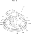
FIG. 3 is a perspective view illustrating a structure of a vehicle door coupling device of the present disclosure. -
FIG. 4 is a perspective view in an oblique upward direction from the lower side inFIG. 3 . -
FIG. 5 is a perspective view illustrating a first member according to an embodiment of the present disclosure. -
FIG. 6 is a perspective view in an oblique upward direction from the lower side inFIG. 5 . -
FIG. 7 is a perspective view illustrating the vehicle door coupling device in a temporary coupling position. -
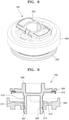
FIG. 8 is a perspective view illustrating the vehicle door coupling device from the lower side inFIG. 7 . -
FIG. 9 is a cross-sectional view taken along line IX-IX ofFIG. 7 . -
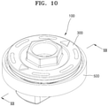
FIG. 10 is a perspective view illustrating the vehicle door coupling device when a shaft is lowered from the state shown inFIG. 7 . -
FIG. 11 is a perspective view illustrating the vehicle door coupling device from the lower side inFIG. 10 . -
FIG. 12 is a cross-sectional view taken along line XII-XII ofFIG. 10 . -
FIG. 13 is a perspective view illustrating a state in which the shaft is inserted into a second member and a crossbar protrudes from the second member. -
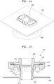
FIG. 14 is a perspective view illustrating the vehicle door coupling device from the lower side inFIG. 13 . -
FIG. 15 is a cross-sectional view taken along line XV-XV ofFIG. 10 . -
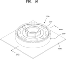
FIG. 16 is a perspective view illustrating the vehicle door coupling device in a final coupling position. -
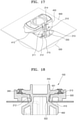
FIG. 17 is a perspective view from the lower side inFIG. 16 . -
FIG. 18 is a cross-sectional view taken along line XVIII-XVIII ofFIG. 16 . - Hereinafter, a vehicle door coupling device will be described in detail with reference to the accompanying drawings according to embodiments of the present disclosure.
- A vehicle
door coupling device 100 of the present disclosure is for mechanically coupling together afirst member 500 having afirst hole 501 and asecond member 600 having asecond hole 601 at a position corresponding to thefirst hole 501. - Specifically, the
first member 500 having thefirst hole 501 corresponds to a door modular panel. Electric components necessary for a door of an automobile are modularized and installed on the door modular panel, and for example, components such as a window regulator and a speaker may be installed on the door modular panel. After given electric components are installed on the door modular panel, the door modular panel is attached to a door inner panel. - As shown in
FIGS. 5 and 6 , thefirst hole 501 is formed in thefirst member 500 such that ashaft 200 may be inserted into thefirst member 500. Thefirst hole 501 has a long hole shape, and an engagingprotrusion 502 is provided on the inner surface of thefirst hole 501. The engagingprotrusion 502 is fitted into a vertical groove and a horizontal groove of theshaft 200 and protrudes from a rear side (based onFIG. 5 ) of thefirst member 500. Specifically, the engagingprotrusion 502 protrudes toward the inside of thefirst hole 501. - An
anti-loosening groove 503 is provided in a peripheral region of thefirst hole 501, and ananti-loosening structure 320 provided on thestopper 300 of theshaft 200 may be fitted and trapped in theanti-loosening groove 503. Theanti-loosening groove 503 is provided in the periphery region of thefirst hole 501 in an upper side (based onFIG. 5 ) of thefirst member 500. After theshaft 200 is rotated to a final coupling position (the position shown inFIGS. 16 to 18 ), theanti-loosening structure 320 of thestopper 300 is fitted into theanti-loosening groove 503 such that a final coupling state may be maintained. - The
second member 600 corresponds to a door inner panel, and thesecond hole 601 is formed in thesecond member 600 at a position corresponding to thefirst hole 501 of thefirst member 500. Thesecond hole 601 has a long hole shape substantially corresponding to acrossbar 400. - The vehicle
door coupling device 100 includes theshaft 200, thestopper 300, and thecrossbar 400. - The
shaft 200 has a vertically extending pillar shape such that theshaft 200 may be rotatably fitted into thefirst hole 501 of thefirst member 500 and thesecond hole 601 of thesecond member 600 and may rotatably pass therethrough. Thestopper 300 is provided on the upper end of theshaft 200, and thecrossbar 400 is formed on the lower end of theshaft 200. (The terms "upper end" and "lower end" are given based onFIG. 4 for ease of illustration.) - A
position maintaining structure 210 is provided on theshaft 200. Owing to theposition maintaining structure 210, theshaft 200 may be temporarily coupled to thefirst member 500 in a vertically movable manner without being separated from thefirst member 500 in a temporary coupling position (the position shown inFIGS. 4 to 12 ), and the state in which a rear side of thecrossbar 400 partially protrudes from thesecond member 600 may be maintained in the temporary coupling position. - Specifically, the
position maintaining structure 210 includes: avertical groove portion 211 which is provided in an outer side of theshaft 200 and vertically extends toward an end of theshaft 200 from the other end of theshaft 200 to receive the engagingprotrusion 502 therein and guide the engagingprotrusion 502; and ahorizontal groove portion 212 which horizontally extends from an end portion of thevertical groove portion 211 to allow rotation of theshaft 200, wherein thevertical groove portion 211 is provided with aposition maintaining protrusion 213 which prevents the engagingprotrusion 502 of thefirst hole 501 from entering thehorizontal groove portion 212 in the temporary coupling position. Specifically, thepositioning protrusion 213 may be provided on a portion through which thevertical groove portion 211 and thehorizontal groove portion 212 are connected to each other. - In addition, a separation-preventing
protrusion 214 is provided on an upper entrance of thevertical groove portion 211, and thus, the engagingprotrusion 502 inserted into thevertical groove portion 211 is prevented from being separated from thevertical groove portion 211 by the separation-preventingprotrusion 214. The engagingprotrusion 502 allows upward or downward movement of theshaft 200 in the temporary coupling position while the engagingprotrusion 502 moves upward or downward between the separation-preventingprotrusion 214 and theposition maintaining protrusion 213. - Specifically, when the
shaft 200 enters thefirst hole 501 of thefirst member 500, the engagingprotrusion 502 of thefirst member 500 is inserted into thevertical groove portion 211 while being moved over the separation-preventingprotrusion 214. In this case, thevertical groove portion 211 prevents the engagingprotrusion 502 from moving left and right, thereby preventing theshaft 200 from rotating relative to thefirst member 500. In other words, thevertical groove portion 211 has a function of guiding the movement of the engagingprotrusion 502 . - In addition, the engaging
protrusion 502 having entered thevertical groove portion 211 may move up to theposition maintaining protrusion 213, and in the temporary coupling position, the engagingprotrusion 502 may move between the separation-preventingprotrusion 214 and theposition maintaining protrusion 213. Therefore, theshaft 200 may be vertically moved by a predetermined distance in the temporary coupling position. Therefore, when a worker puts thesecond member 600 on the rear side of thefirst member 500 in the temporary coupling position, interference caused by thecrossbar 400 of theshaft 200 may be minimized. Especially, thecrossbar 400 of theshaft 200 is configured to be freely moved in an axial direction by a distance of about 3 mm to about 6.5 mm from the rear side of thefirst member 500 in the temporary coupling position, and thus, thecrossbar 400 of theshaft 200 may minimally obstruct the movement of thefirst member 500 to thesecond member 600. - The
horizontal groove portion 212 is provided with a rotation-suppressingprotrusion 215 for suppressing the rotation of theshaft 200, and thus, the rotation of theshaft 200 is prevented unless a force equal to or greater than a given value is applied to theshaft 200 after the engagingprotrusion 502 enters thehorizontal groove portion 212. - Specifically, if the engaging
protrusion 502, of which left and right rotation in thevertical groove portion 211 is suppressed, is allowed to rotate immediately after the engagingprotrusion 502 is vertically moved downward into thehorizontal groove portion 212, thesecond member 600 may be fixed to thefirst member 500 due to an unintended rotation of theshaft 200, and thus, the rotation-suppressingprotrusion 215 is provided to prevent this. Until a sufficient amount of force for moving over the rotation-suppressingprotrusion 215 is applied, the rotation of theshaft 200 is suppressed. - The
stopper 300, which is provided on a side of theshaft 200 for supporting thefirst member 500, is located on an upper side of theshaft 200. Thestopper 300 has a disk shape and is configured such that the lower surface of thestopper 300 presses the upper surface of thefirst member 500 in the final coupling position while making contact with the upper surface of thefirst member 500. - Specifically, as the lower surface of the
stopper 300 makes contact with the upper surface of thefirst member 500, thestopper 300 supports thefirst member 500. - The
stopper 300 has a rear side which faces thefirst member 500, and a sealing material 301 is provided on the rear side of thestopper 300 to guarantee watertightness when thestopper 300 makes contact with thefirst member 500. Specifically, the sealingmaterial 310 may be a rubber material having a ring shape and configured to provide watertight sealing along the periphery of thefirst hole 501 of thefirst member 500. - In addition, the
anti-loosening structure 320 is provided on thestopper 300 to prevent theshaft 200 from loosening after being rotated to the final coupling position. Theanti-loosening structure 320 is a protrusion protruding from the rear side of thestopper 300 and configured to be fitted into theanti-loosening groove 503 of thefirst member 500. When theshaft 200 is rotated to the final coupling position, theanti-loosening structure 320 is inserted into theanti-loosening groove 503 of thefirst member 500, thereby fixing theshaft 200 in the final coupling position. - The
crossbar 400 is provided on the other side of theshaft 200, and when theshaft 200 is rotated to the final coupling position, thecrossbar 400 supports thesecond member 600 and fixes thesecond member 600 to thefirst member 500. Thecrossbar 400 is located on the lower end of theshaft 200 and generally has a horizontally extending bar shape. - An
inclined surface 410 is formed on an upper surface of thecrossbar 400, and when theshaft 200 is rotated in one direction, the distance between thefirst member 500 and thesecond member 600 is reduced owing to theinclined surface 410. That is, the thickness of thecrossbar 400 increases along theinclined surface 410 such that when theshaft 200 is rotated, the distance between thefirst member 500 and thesecond member 600 may be reduced along theinclined surface 410. In the temporary coupling position, thecrossbar 400 does not protrude from the rear side of thefirst member 500 which faces thesecond member 600, and thus, when thesecond member 600 is coupled to thefirst member 500 while bringing thesecond member 600 into contact with the rear side of thefirst member 500, thecrossbar 400 does not interfere with thefirst member 500. - The vehicle
door coupling device 100 of the present disclosure will now be described in more detail with reference to the accompanying drawings. -
FIGS. 7 to 9 are views illustrating a state in which theshaft 200 is temporarily coupled to thefirst member 500. While a door module is moved toward a door in a state in which necessary electric components (not shown) are installed on the door module, theshaft 200 is coupled to thefirst member 500. Therefore, additional fastening means (such as bolts) for installing thefirst member 500 on the door may not be necessary. - In such a temporary state, the
crossbar 400 to be supported by thesecond member 600 is placed in thefirst member 500 with an end of thecrossbar 400 protruding from thefirst member 500 by about 3 mm as shown inFIG. 8 , and thus when thefirst member 500 is moved toward thesecond member 600, theshaft 200 does not act as an additional obstacle. - Moreover, because the
crossbar 400 slightly protrudes, thefirst member 500 may be easily put in place. That is, thecrossbar 400, which protrudes from the rear side of thefirst member 500 by about 3 mm, may not act as an obstacle but may facilitate position alignment while thefirst member 500 is moved to thesecond member 600. -
FIGS. 10 to 12 illustrate a state in which theshaft 200 is moved downward while being maintained in the temporary coupling position. Specifically, the state in which theshaft 200 is moved downward is a preliminary state before the final coupling position. Referring toFIG. 10 in comparison withFIG. 7 , theshaft 200 is moved downward through the upper end of thefirst member 500. Specifically, theshaft 200 is moved downward until the engagingprotrusion 502 reaches theposition maintaining protrusion 213 in a state in which the engagingprotrusion 502 is still in thevertical groove portion 211. At this time, thecrossbar 400 of theshaft 200 may protrude by about 6.5 mm. - As described above, the
shaft 200 of the present disclosure is configured such that thecrossbar 400 may be vertically movable within the range of 3 mm to 6.5 mm from the rear side of thesecond member 600. - In addition, because the engaging
protrusion 502 of thefirst member 500 is in thevertical groove portion 211, theshaft 200 is movable only in the vertical direction in a state in which the rotation of theshaft 200 is restricted. -
FIGS. 13 to 15 illustrate a state in which thecrossbar 400 is inserted into thesecond hole 601 of thesecond member 600. Because thecrossbar 400 is in a protruding state as described above, thecrossbar 400 may be easily aligned with thesecond hole 601 of thesecond member 600. That is, thecrossbar 400 is not easily aligned with thesecond hole 601 of thesecond member 600 if thecrossbar 400 is kept inside thefirst member 500 and does not protrude from thefirst member 500. - In this case, the
second member 600 is spaced apart from thefirst member 500, and thefirst hole 501 of thefirst member 500 and thesecond hole 601 of thesecond member 600 are aligned with each other. In this state, thecrossbar 400 may be moved to the final coupling position shown inFIGS. 16 to 18 by rotating thecrossbar 400. -
FIGS. 16 to 18 illustrate the final coupling position. When theshaft 200 is rotated by 90° or more, thestopper 300 supports thefirst member 500, and the upper surface of thecrossbar 400 supports the lower surface of thesecond member 600, such that thefirst member 500 and thesecond member 600 may be clamped to each other - That is, as shown in
FIG. 18 , thefirst member 500 and thesecond member 600 may be securely coupled to each other in a state in which thestopper 300 supports thefirst member 500 and thecrossbar 400 supports thesecond member 600. In this case, theanti-loosening structure 320 suppresses reverse rotation of theshaft 200, and thus, the clamping between thefirst member 500 and thesecond member 600 is maintained. - In addition, because the sealing
material 310 of thestopper 300 is in close contact with the surface of thefirst member 500, permeation of water between thefirst member 500 and thestopper 300 may be prevented, and the inside of the door may be securely kept in a watertight state. - The vehicle door coupling device of the present disclosure has the following effects.
- According to the present disclosure, in a state in which the vehicle door coupling device is temporarily fitted into a door modular panel, the vehicle door coupling device may be simply and fixedly inserted into a door inner panel, such that the door modular panel and the door inner panel may be easily coupled to each other.
- In addition, because the vehicle door coupling device of the present disclosure is provided with the sealing material on the shaft, the gap between the shaft and the door modular panel may be securely sealed, and thus, a watertight space may be easily formed in the door.
- Furthermore, in the temporary coupling position, the crossbar is freely movable in a vertical direction within the range of 3 mm to 6.5 mm, and thus the crossbar may not act as a significant obstacle when the door inner panel and the door modular panel are coupled to each other.
- Furthermore, in the temporary coupling position, the engaging protrusion is guided in the vertical groove portion only in the vertical direction, and thus, the rotation of the shaft may be securely prevented. However, if the vertical groove portion is not provided, the shaft may be rotated even in a state in which the shaft is partially inserted, that is, the shaft may be unintendedly rotated before the shaft is fully inserted. This problem may be solved by the present disclosure.
- In addition, according to the present disclosure, owing to the rotation-suppressing protrusion provided on the horizontal groove portion, unintended rotation of the shaft in the horizontal groove portion may be prevented.
- In addition, according to the present disclosure, the anti-loosening structure is configured to be trapped in the loosening groove at a completely fastened position, and thus, loosening (reverse rotation) may be prevented after complete fastening.
- While the vehicle door coupling device of the present disclosure has been described with reference to various embodiments, the vehicle door coupling device is not limited to the embodiments, and it will be apparent that anything that can be reasonably interpreted from the scope of the present disclosure is included in the scope of the present disclosure.
Claims (7)
- A vehicle door coupling device for mechanically coupling together a first member having a first hole inside which an engaging protrusion is provided and a second member having a second hole at a position corresponding to the first hole, the vehicle door coupling device comprising:a shaft shaped to be fitted into the first hole of the first member and the second hole of the second member and rotatably pass therethrough, the shaft extending in a vertical direction;a stopper provided on a side of the shaft and configured to support the first member;a crossbar provided on another side of the shaft and configured such that when the shaft is rotated to a final coupling position, the crossbar fixedly couples the second member to the first member while supporting the second member; anda position maintaining structure provided on the shaft, the position maintaining structure being configured to allow the shaft to be temporarily coupled to the first member in a temporary coupling position in a state in which the shaft is vertically movable without being separated from the first member and being configured to maintain a state in which a rear side of the crossbar partially protrudes from the second member in the temporary coupling position.
- The vehicle door coupling device of claim 1, wherein the position maintaining structure comprises:a vertical groove portion which is provided in an outer side of the shaft, extends in the vertical direction toward the side of the shaft from the other side of the shaft, and is configured to receive the engaging protrusion therein and guide the engaging protrusion; anda horizontal groove portion which extends in a horizontal direction from an end of the vertical groove portion and is configured to allow rotation of the shaft,wherein a position maintaining protrusion is provided in the vertical groove portion to prevent the engaging protrusion of the first hole from entering the horizontal groove portion in the temporary coupling position.
- The vehicle door coupling device of claim 2, wherein the position maintaining protrusion is provided on a portion through which the vertical groove portion and the horizontal groove portion are connected to each other.
- The vehicle door coupling device of claim 3, whereina separation-preventing protrusion is provided on an entrance of the vertical groove portion to prevent separation of the engaging protrusion inserted into the vertical groove portion, andthe engaging protrusion allows the shaft to move upward or downward in the temporary coupling position while the engaging protrusion vertically moves between the separation-preventing protrusion and the position maintaining protrusion.
- The vehicle door coupling device of claim 1, wherein a rotation-suppressing protrusion is provided in the horizontal groove portion to suppress rotation of the shaft such that unless a force equal to or greater than a given value is applied to the shaft, rotation of the shaft along the horizontal groove portion is suppressed.
- The vehicle door coupling device of claim 1, wherein the stopper of the shaft has a rear side facing the first member, and a sealing material is provided on the rear side to guarantee watertightness when the stopper is brought into contact with the first member.
- The vehicle door coupling device of claim 1, wherein an anti-loosening structure is provided on the stopper of the shaft to prevent loosening when the shaft is rotated to the final coupling position.
Applications Claiming Priority (2)
| Application Number | Priority Date | Filing Date | Title |
|---|---|---|---|
| KR1020190039103A KR102230795B1 (en) | 2019-04-03 | 2019-04-03 | Coupling apparatus for car door |
| PCT/KR2020/004519 WO2020204629A2 (en) | 2019-04-03 | 2020-04-02 | Vehicle door coupling device |
Publications (3)
| Publication Number | Publication Date |
|---|---|
| EP3950393A2 true EP3950393A2 (en) | 2022-02-09 |
| EP3950393A4 EP3950393A4 (en) | 2022-11-23 |
| EP3950393B1 EP3950393B1 (en) | 2024-09-18 |
Family
ID=72666245
Family Applications (1)
| Application Number | Title | Priority Date | Filing Date |
|---|---|---|---|
| EP20784465.5A Active EP3950393B1 (en) | 2019-04-03 | 2020-04-02 | Vehicle door coupling device |
Country Status (5)
| Country | Link |
|---|---|
| US (1) | US11919375B2 (en) |
| EP (1) | EP3950393B1 (en) |
| KR (1) | KR102230795B1 (en) |
| CN (1) | CN216033656U (en) |
| WO (1) | WO2020204629A2 (en) |
Families Citing this family (3)
| Publication number | Priority date | Publication date | Assignee | Title |
|---|---|---|---|---|
| DE102019218580A1 (en) * | 2019-08-06 | 2021-02-11 | Brose Fahrzeugteile Se & Co. Kommanditgesellschaft, Bamberg | Door module of a vehicle door |
| KR102852729B1 (en) * | 2022-11-23 | 2025-08-29 | 주식회사 광진 | Coupling apparatus for car door |
| KR102900291B1 (en) * | 2023-08-16 | 2025-12-15 | 주식회사 광진 | Coupling apparatus for car door |
Family Cites Families (16)
| Publication number | Priority date | Publication date | Assignee | Title |
|---|---|---|---|---|
| US2858156A (en) * | 1955-04-08 | 1958-10-28 | United Carr Fastener Corp | Sealing bushing for a fastening device |
| US2922211A (en) * | 1955-10-04 | 1960-01-26 | Illinois Tool Works | Quick fastener unit |
| US4911726A (en) * | 1988-09-13 | 1990-03-27 | Rexnord Holdings Inc. | Fastener/retaining ring assembly |
| US5399053A (en) * | 1993-04-27 | 1995-03-21 | Avibank Mfg., Inc. | Quick action panel fastener assembly including a cup enclosed retainer receiving a bolt therein |
| KR200168232Y1 (en) * | 1997-06-30 | 2000-03-02 | 김태구 | Clip for cowl flux have prevention function |
| US6860689B1 (en) * | 2001-05-02 | 2005-03-01 | Pilgrim Screw Corporation | Fastening assemblies and components thereof |
| KR100460466B1 (en) * | 2002-06-25 | 2004-12-14 | (주)파크랜드 | Auto Locking Apparatus of Container for Trailer |
| KR20060015895A (en) | 2004-08-16 | 2006-02-21 | 현대자동차주식회사 | Door module coupling structure of automobile |
| EP2589367A4 (en) * | 2010-06-30 | 2014-09-03 | Terumo Corp | Connector and connector assembly |
| TWM449183U (en) * | 2012-10-11 | 2013-03-21 | Hanwit Prec Ind Ltd | Sheet-to-sheet quick positioning device |
| JP6216210B2 (en) | 2013-10-25 | 2017-10-18 | 株式会社ニフコ | Hose connector |
| US10266994B2 (en) * | 2015-09-10 | 2019-04-23 | Newpark Mats & Integrated Services Llc | Apparatus and methods for connecting components of a support surface |
| FR3058484B1 (en) | 2016-11-08 | 2020-01-24 | Illinois Tool Works Inc | DEVICE AND METHOD FOR ATTACHING AT LEAST TWO ELEMENTS, SUCH AS A DOOR MODULE AND A DOOR STRUCTURE OF A MOTOR VEHICLE |
| US10968938B2 (en) * | 2017-11-03 | 2021-04-06 | Illinois Tool Works Inc. | Connector with enhanced mounting process |
| KR101964413B1 (en) * | 2017-12-27 | 2019-04-01 | 주식회사 광진 | Coupling apparatus for car door |
| TWI761062B (en) * | 2021-02-03 | 2022-04-11 | 伍鐌科技股份有限公司 | Fastener structure and assembly method thereof |
-
2019
- 2019-04-03 KR KR1020190039103A patent/KR102230795B1/en active Active
-
2020
- 2020-04-02 US US17/422,634 patent/US11919375B2/en active Active
- 2020-04-02 EP EP20784465.5A patent/EP3950393B1/en active Active
- 2020-04-02 WO PCT/KR2020/004519 patent/WO2020204629A2/en not_active Ceased
- 2020-04-02 CN CN202090000351.1U patent/CN216033656U/en active Active
Also Published As
| Publication number | Publication date |
|---|---|
| CN216033656U (en) | 2022-03-15 |
| EP3950393B1 (en) | 2024-09-18 |
| US20220089006A1 (en) | 2022-03-24 |
| EP3950393A4 (en) | 2022-11-23 |
| WO2020204629A3 (en) | 2020-11-19 |
| KR102230795B1 (en) | 2021-03-22 |
| US11919375B2 (en) | 2024-03-05 |
| WO2020204629A2 (en) | 2020-10-08 |
| KR20200117250A (en) | 2020-10-14 |
Similar Documents
| Publication | Publication Date | Title |
|---|---|---|
| US11919375B2 (en) | Vehicle door coupling device | |
| US6698140B2 (en) | Door structure for vehicle | |
| US20030096510A1 (en) | Modular vehicle door and method of assembly | |
| US10625587B2 (en) | Vehicle door sash structure | |
| US6920720B2 (en) | Motor vehicle door and method for assembling the motor vehicle door | |
| US10676975B2 (en) | Door assembly with collapsible carrier | |
| US10953731B2 (en) | Door assembly with collapsible carrier and water shield | |
| JP2008103325A (en) | Automotive door cable connectors | |
| US9511725B2 (en) | Wiring harness wiring structure | |
| MX2007008284A (en) | Support module for vehicle doors and method of mounting same. | |
| US10322623B2 (en) | Roof closure assembly | |
| WO2012120720A1 (en) | Wire harness routing structure | |
| US7423224B2 (en) | Wire bundle routing assembly and installation method | |
| KR101964413B1 (en) | Coupling apparatus for car door | |
| KR102273864B1 (en) | Coupling apparatus for car door | |
| US20240166033A1 (en) | Coupling apparatus for car door | |
| EP4523936A1 (en) | Outer trim panel, profile assembly, glass run seal, sealing system assembly of window glass, door, and vehicle | |
| US12194819B2 (en) | Door module | |
| JP5007607B2 (en) | Automobile sunroof drainage structure | |
| KR20060015895A (en) | Door module coupling structure of automobile | |
| US11499356B2 (en) | Vehicle window regulator with window protection system | |
| CN222037458U (en) | Combined production system for tooling and car door panels | |
| US20220153100A1 (en) | Door module of a vehicle door and vehicle door having the door module | |
| KR100521685B1 (en) | Door window regulator motor mounting means for automobile | |
| JPS6112251Y2 (en) |
Legal Events
| Date | Code | Title | Description |
|---|---|---|---|
| STAA | Information on the status of an ep patent application or granted ep patent |
Free format text: STATUS: THE INTERNATIONAL PUBLICATION HAS BEEN MADE |
|
| PUAI | Public reference made under article 153(3) epc to a published international application that has entered the european phase |
Free format text: ORIGINAL CODE: 0009012 |
|
| STAA | Information on the status of an ep patent application or granted ep patent |
Free format text: STATUS: REQUEST FOR EXAMINATION WAS MADE |
|
| 17P | Request for examination filed |
Effective date: 20210720 |
|
| AK | Designated contracting states |
Kind code of ref document: A2 Designated state(s): AL AT BE BG CH CY CZ DE DK EE ES FI FR GB GR HR HU IE IS IT LI LT LU LV MC MK MT NL NO PL PT RO RS SE SI SK SM TR |
|
| DAV | Request for validation of the european patent (deleted) | ||
| DAX | Request for extension of the european patent (deleted) | ||
| A4 | Supplementary search report drawn up and despatched |
Effective date: 20221026 |
|
| RIC1 | Information provided on ipc code assigned before grant |
Ipc: F16B 21/04 20060101ALI20221020BHEP Ipc: B60J 5/04 20060101AFI20221020BHEP |
|
| RIC1 | Information provided on ipc code assigned before grant |
Ipc: F16B 21/04 20060101ALI20240226BHEP Ipc: B60J 5/04 20060101AFI20240226BHEP |
|
| GRAP | Despatch of communication of intention to grant a patent |
Free format text: ORIGINAL CODE: EPIDOSNIGR1 |
|
| STAA | Information on the status of an ep patent application or granted ep patent |
Free format text: STATUS: GRANT OF PATENT IS INTENDED |
|
| INTG | Intention to grant announced |
Effective date: 20240408 |
|
| GRAS | Grant fee paid |
Free format text: ORIGINAL CODE: EPIDOSNIGR3 |
|
| GRAA | (expected) grant |
Free format text: ORIGINAL CODE: 0009210 |
|
| STAA | Information on the status of an ep patent application or granted ep patent |
Free format text: STATUS: THE PATENT HAS BEEN GRANTED |
|
| AK | Designated contracting states |
Kind code of ref document: B1 Designated state(s): AL AT BE BG CH CY CZ DE DK EE ES FI FR GB GR HR HU IE IS IT LI LT LU LV MC MK MT NL NO PL PT RO RS SE SI SK SM TR |
|
| REG | Reference to a national code |
Ref country code: GB Ref legal event code: FG4D |
|
| REG | Reference to a national code |
Ref country code: CH Ref legal event code: EP |
|
| REG | Reference to a national code |
Ref country code: IE Ref legal event code: FG4D |
|
| REG | Reference to a national code |
Ref country code: DE Ref legal event code: R096 Ref document number: 602020037994 Country of ref document: DE |
|
| REG | Reference to a national code |
Ref country code: LT Ref legal event code: MG9D |
|
| PG25 | Lapsed in a contracting state [announced via postgrant information from national office to epo] |
Ref country code: NO Free format text: LAPSE BECAUSE OF FAILURE TO SUBMIT A TRANSLATION OF THE DESCRIPTION OR TO PAY THE FEE WITHIN THE PRESCRIBED TIME-LIMIT Effective date: 20241218 |
|
| PG25 | Lapsed in a contracting state [announced via postgrant information from national office to epo] |
Ref country code: GR Free format text: LAPSE BECAUSE OF FAILURE TO SUBMIT A TRANSLATION OF THE DESCRIPTION OR TO PAY THE FEE WITHIN THE PRESCRIBED TIME-LIMIT Effective date: 20241219 Ref country code: FI Free format text: LAPSE BECAUSE OF FAILURE TO SUBMIT A TRANSLATION OF THE DESCRIPTION OR TO PAY THE FEE WITHIN THE PRESCRIBED TIME-LIMIT Effective date: 20240918 |
|
| PG25 | Lapsed in a contracting state [announced via postgrant information from national office to epo] |
Ref country code: BG Free format text: LAPSE BECAUSE OF FAILURE TO SUBMIT A TRANSLATION OF THE DESCRIPTION OR TO PAY THE FEE WITHIN THE PRESCRIBED TIME-LIMIT Effective date: 20240918 |
|
| PG25 | Lapsed in a contracting state [announced via postgrant information from national office to epo] |
Ref country code: LV Free format text: LAPSE BECAUSE OF FAILURE TO SUBMIT A TRANSLATION OF THE DESCRIPTION OR TO PAY THE FEE WITHIN THE PRESCRIBED TIME-LIMIT Effective date: 20240918 |
|
| PG25 | Lapsed in a contracting state [announced via postgrant information from national office to epo] |
Ref country code: HR Free format text: LAPSE BECAUSE OF FAILURE TO SUBMIT A TRANSLATION OF THE DESCRIPTION OR TO PAY THE FEE WITHIN THE PRESCRIBED TIME-LIMIT Effective date: 20240918 |
|
| REG | Reference to a national code |
Ref country code: NL Ref legal event code: MP Effective date: 20240918 |
|
| PG25 | Lapsed in a contracting state [announced via postgrant information from national office to epo] |
Ref country code: RS Free format text: LAPSE BECAUSE OF FAILURE TO SUBMIT A TRANSLATION OF THE DESCRIPTION OR TO PAY THE FEE WITHIN THE PRESCRIBED TIME-LIMIT Effective date: 20241218 |
|
| PG25 | Lapsed in a contracting state [announced via postgrant information from national office to epo] |
Ref country code: RS Free format text: LAPSE BECAUSE OF FAILURE TO SUBMIT A TRANSLATION OF THE DESCRIPTION OR TO PAY THE FEE WITHIN THE PRESCRIBED TIME-LIMIT Effective date: 20241218 Ref country code: NO Free format text: LAPSE BECAUSE OF FAILURE TO SUBMIT A TRANSLATION OF THE DESCRIPTION OR TO PAY THE FEE WITHIN THE PRESCRIBED TIME-LIMIT Effective date: 20241218 Ref country code: LV Free format text: LAPSE BECAUSE OF FAILURE TO SUBMIT A TRANSLATION OF THE DESCRIPTION OR TO PAY THE FEE WITHIN THE PRESCRIBED TIME-LIMIT Effective date: 20240918 Ref country code: HR Free format text: LAPSE BECAUSE OF FAILURE TO SUBMIT A TRANSLATION OF THE DESCRIPTION OR TO PAY THE FEE WITHIN THE PRESCRIBED TIME-LIMIT Effective date: 20240918 Ref country code: GR Free format text: LAPSE BECAUSE OF FAILURE TO SUBMIT A TRANSLATION OF THE DESCRIPTION OR TO PAY THE FEE WITHIN THE PRESCRIBED TIME-LIMIT Effective date: 20241219 Ref country code: FI Free format text: LAPSE BECAUSE OF FAILURE TO SUBMIT A TRANSLATION OF THE DESCRIPTION OR TO PAY THE FEE WITHIN THE PRESCRIBED TIME-LIMIT Effective date: 20240918 Ref country code: BG Free format text: LAPSE BECAUSE OF FAILURE TO SUBMIT A TRANSLATION OF THE DESCRIPTION OR TO PAY THE FEE WITHIN THE PRESCRIBED TIME-LIMIT Effective date: 20240918 |
|
| REG | Reference to a national code |
Ref country code: AT Ref legal event code: MK05 Ref document number: 1724406 Country of ref document: AT Kind code of ref document: T Effective date: 20240918 |
|
| PG25 | Lapsed in a contracting state [announced via postgrant information from national office to epo] |
Ref country code: NL Free format text: LAPSE BECAUSE OF FAILURE TO SUBMIT A TRANSLATION OF THE DESCRIPTION OR TO PAY THE FEE WITHIN THE PRESCRIBED TIME-LIMIT Effective date: 20240918 |
|
| PG25 | Lapsed in a contracting state [announced via postgrant information from national office to epo] |
Ref country code: PT Free format text: LAPSE BECAUSE OF FAILURE TO SUBMIT A TRANSLATION OF THE DESCRIPTION OR TO PAY THE FEE WITHIN THE PRESCRIBED TIME-LIMIT Effective date: 20250120 Ref country code: IS Free format text: LAPSE BECAUSE OF FAILURE TO SUBMIT A TRANSLATION OF THE DESCRIPTION OR TO PAY THE FEE WITHIN THE PRESCRIBED TIME-LIMIT Effective date: 20250118 |
|
| PG25 | Lapsed in a contracting state [announced via postgrant information from national office to epo] |
Ref country code: RO Free format text: LAPSE BECAUSE OF FAILURE TO SUBMIT A TRANSLATION OF THE DESCRIPTION OR TO PAY THE FEE WITHIN THE PRESCRIBED TIME-LIMIT Effective date: 20240918 Ref country code: SM Free format text: LAPSE BECAUSE OF FAILURE TO SUBMIT A TRANSLATION OF THE DESCRIPTION OR TO PAY THE FEE WITHIN THE PRESCRIBED TIME-LIMIT Effective date: 20240918 |
|
| PG25 | Lapsed in a contracting state [announced via postgrant information from national office to epo] |
Ref country code: ES Free format text: LAPSE BECAUSE OF FAILURE TO SUBMIT A TRANSLATION OF THE DESCRIPTION OR TO PAY THE FEE WITHIN THE PRESCRIBED TIME-LIMIT Effective date: 20240918 |
|
| PG25 | Lapsed in a contracting state [announced via postgrant information from national office to epo] |
Ref country code: AT Free format text: LAPSE BECAUSE OF FAILURE TO SUBMIT A TRANSLATION OF THE DESCRIPTION OR TO PAY THE FEE WITHIN THE PRESCRIBED TIME-LIMIT Effective date: 20240918 Ref country code: EE Free format text: LAPSE BECAUSE OF FAILURE TO SUBMIT A TRANSLATION OF THE DESCRIPTION OR TO PAY THE FEE WITHIN THE PRESCRIBED TIME-LIMIT Effective date: 20240918 |
|
| PG25 | Lapsed in a contracting state [announced via postgrant information from national office to epo] |
Ref country code: PL Free format text: LAPSE BECAUSE OF FAILURE TO SUBMIT A TRANSLATION OF THE DESCRIPTION OR TO PAY THE FEE WITHIN THE PRESCRIBED TIME-LIMIT Effective date: 20240918 Ref country code: CZ Free format text: LAPSE BECAUSE OF FAILURE TO SUBMIT A TRANSLATION OF THE DESCRIPTION OR TO PAY THE FEE WITHIN THE PRESCRIBED TIME-LIMIT Effective date: 20240918 |
|
| PG25 | Lapsed in a contracting state [announced via postgrant information from national office to epo] |
Ref country code: IT Free format text: LAPSE BECAUSE OF FAILURE TO SUBMIT A TRANSLATION OF THE DESCRIPTION OR TO PAY THE FEE WITHIN THE PRESCRIBED TIME-LIMIT Effective date: 20240918 Ref country code: SK Free format text: LAPSE BECAUSE OF FAILURE TO SUBMIT A TRANSLATION OF THE DESCRIPTION OR TO PAY THE FEE WITHIN THE PRESCRIBED TIME-LIMIT Effective date: 20240918 |
|
| REG | Reference to a national code |
Ref country code: DE Ref legal event code: R097 Ref document number: 602020037994 Country of ref document: DE |
|
| PGFP | Annual fee paid to national office [announced via postgrant information from national office to epo] |
Ref country code: DE Payment date: 20250429 Year of fee payment: 6 |
|
| PG25 | Lapsed in a contracting state [announced via postgrant information from national office to epo] |
Ref country code: DK Free format text: LAPSE BECAUSE OF FAILURE TO SUBMIT A TRANSLATION OF THE DESCRIPTION OR TO PAY THE FEE WITHIN THE PRESCRIBED TIME-LIMIT Effective date: 20240918 |
|
| PGFP | Annual fee paid to national office [announced via postgrant information from national office to epo] |
Ref country code: FR Payment date: 20250428 Year of fee payment: 6 |
|
| PLBE | No opposition filed within time limit |
Free format text: ORIGINAL CODE: 0009261 |
|
| STAA | Information on the status of an ep patent application or granted ep patent |
Free format text: STATUS: NO OPPOSITION FILED WITHIN TIME LIMIT |
|
| 26N | No opposition filed |
Effective date: 20250619 |
|
| PG25 | Lapsed in a contracting state [announced via postgrant information from national office to epo] |
Ref country code: SE Free format text: LAPSE BECAUSE OF FAILURE TO SUBMIT A TRANSLATION OF THE DESCRIPTION OR TO PAY THE FEE WITHIN THE PRESCRIBED TIME-LIMIT Effective date: 20240918 |
|
| REG | Reference to a national code |
Ref country code: CH Ref legal event code: H13 Free format text: ST27 STATUS EVENT CODE: U-0-0-H10-H13 (AS PROVIDED BY THE NATIONAL OFFICE) Effective date: 20251125 |
|
| PG25 | Lapsed in a contracting state [announced via postgrant information from national office to epo] |
Ref country code: LU Free format text: LAPSE BECAUSE OF NON-PAYMENT OF DUE FEES Effective date: 20250402 |
|
| PG25 | Lapsed in a contracting state [announced via postgrant information from national office to epo] |
Ref country code: MC Free format text: LAPSE BECAUSE OF FAILURE TO SUBMIT A TRANSLATION OF THE DESCRIPTION OR TO PAY THE FEE WITHIN THE PRESCRIBED TIME-LIMIT Effective date: 20240918 |
|
| GBPC | Gb: european patent ceased through non-payment of renewal fee |
Effective date: 20250402 |
|
| REG | Reference to a national code |
Ref country code: BE Ref legal event code: MM Effective date: 20250430 |
|
| PG25 | Lapsed in a contracting state [announced via postgrant information from national office to epo] |
Ref country code: GB Free format text: LAPSE BECAUSE OF NON-PAYMENT OF DUE FEES Effective date: 20250402 |
|
| PG25 | Lapsed in a contracting state [announced via postgrant information from national office to epo] |
Ref country code: BE Free format text: LAPSE BECAUSE OF NON-PAYMENT OF DUE FEES Effective date: 20250430 |
|
| PG25 | Lapsed in a contracting state [announced via postgrant information from national office to epo] |
Ref country code: CH Free format text: LAPSE BECAUSE OF NON-PAYMENT OF DUE FEES Effective date: 20250430 |
|
| PG25 | Lapsed in a contracting state [announced via postgrant information from national office to epo] |
Ref country code: IE Free format text: LAPSE BECAUSE OF NON-PAYMENT OF DUE FEES Effective date: 20250402 |