EP3950270B1 - Thermoplastic resin tube bending method - Google Patents
Thermoplastic resin tube bending method Download PDFInfo
- Publication number
- EP3950270B1 EP3950270B1 EP20850385.4A EP20850385A EP3950270B1 EP 3950270 B1 EP3950270 B1 EP 3950270B1 EP 20850385 A EP20850385 A EP 20850385A EP 3950270 B1 EP3950270 B1 EP 3950270B1
- Authority
- EP
- European Patent Office
- Prior art keywords
- forming
- thermoplastic tube
- molds
- temperature
- mold
- Prior art date
- Legal status (The legal status is an assumption and is not a legal conclusion. Google has not performed a legal analysis and makes no representation as to the accuracy of the status listed.)
- Active
Links
Images




Classifications
-
- B—PERFORMING OPERATIONS; TRANSPORTING
- B29—WORKING OF PLASTICS; WORKING OF SUBSTANCES IN A PLASTIC STATE IN GENERAL
- B29C—SHAPING OR JOINING OF PLASTICS; SHAPING OF MATERIAL IN A PLASTIC STATE, NOT OTHERWISE PROVIDED FOR; AFTER-TREATMENT OF THE SHAPED PRODUCTS, e.g. REPAIRING
- B29C53/00—Shaping by bending, folding, twisting, straightening or flattening; Apparatus therefor
- B29C53/02—Bending or folding
- B29C53/08—Bending or folding of tubes or other profiled members
-
- B—PERFORMING OPERATIONS; TRANSPORTING
- B29—WORKING OF PLASTICS; WORKING OF SUBSTANCES IN A PLASTIC STATE IN GENERAL
- B29C—SHAPING OR JOINING OF PLASTICS; SHAPING OF MATERIAL IN A PLASTIC STATE, NOT OTHERWISE PROVIDED FOR; AFTER-TREATMENT OF THE SHAPED PRODUCTS, e.g. REPAIRING
- B29C35/00—Heating, cooling or curing, e.g. crosslinking or vulcanising; Apparatus therefor
- B29C35/007—Tempering units for temperature control of moulds or cores, e.g. comprising heat exchangers, controlled valves, temperature-controlled circuits for fluids
-
- B—PERFORMING OPERATIONS; TRANSPORTING
- B29—WORKING OF PLASTICS; WORKING OF SUBSTANCES IN A PLASTIC STATE IN GENERAL
- B29C—SHAPING OR JOINING OF PLASTICS; SHAPING OF MATERIAL IN A PLASTIC STATE, NOT OTHERWISE PROVIDED FOR; AFTER-TREATMENT OF THE SHAPED PRODUCTS, e.g. REPAIRING
- B29C37/00—Component parts, details, accessories or auxiliary operations, not covered by group B29C33/00 or B29C35/00
-
- B—PERFORMING OPERATIONS; TRANSPORTING
- B29—WORKING OF PLASTICS; WORKING OF SUBSTANCES IN A PLASTIC STATE IN GENERAL
- B29C—SHAPING OR JOINING OF PLASTICS; SHAPING OF MATERIAL IN A PLASTIC STATE, NOT OTHERWISE PROVIDED FOR; AFTER-TREATMENT OF THE SHAPED PRODUCTS, e.g. REPAIRING
- B29C53/00—Shaping by bending, folding, twisting, straightening or flattening; Apparatus therefor
- B29C53/02—Bending or folding
- B29C53/08—Bending or folding of tubes or other profiled members
- B29C53/083—Bending or folding of tubes or other profiled members bending longitudinally, i.e. modifying the curvature of the tube axis
-
- B—PERFORMING OPERATIONS; TRANSPORTING
- B29—WORKING OF PLASTICS; WORKING OF SUBSTANCES IN A PLASTIC STATE IN GENERAL
- B29C—SHAPING OR JOINING OF PLASTICS; SHAPING OF MATERIAL IN A PLASTIC STATE, NOT OTHERWISE PROVIDED FOR; AFTER-TREATMENT OF THE SHAPED PRODUCTS, e.g. REPAIRING
- B29C53/00—Shaping by bending, folding, twisting, straightening or flattening; Apparatus therefor
- B29C53/80—Component parts, details or accessories; Auxiliary operations
-
- B—PERFORMING OPERATIONS; TRANSPORTING
- B29—WORKING OF PLASTICS; WORKING OF SUBSTANCES IN A PLASTIC STATE IN GENERAL
- B29C—SHAPING OR JOINING OF PLASTICS; SHAPING OF MATERIAL IN A PLASTIC STATE, NOT OTHERWISE PROVIDED FOR; AFTER-TREATMENT OF THE SHAPED PRODUCTS, e.g. REPAIRING
- B29C53/00—Shaping by bending, folding, twisting, straightening or flattening; Apparatus therefor
- B29C53/80—Component parts, details or accessories; Auxiliary operations
- B29C53/84—Heating or cooling
-
- B—PERFORMING OPERATIONS; TRANSPORTING
- B29—WORKING OF PLASTICS; WORKING OF SUBSTANCES IN A PLASTIC STATE IN GENERAL
- B29C—SHAPING OR JOINING OF PLASTICS; SHAPING OF MATERIAL IN A PLASTIC STATE, NOT OTHERWISE PROVIDED FOR; AFTER-TREATMENT OF THE SHAPED PRODUCTS, e.g. REPAIRING
- B29C37/00—Component parts, details, accessories or auxiliary operations, not covered by group B29C33/00 or B29C35/00
- B29C2037/90—Measuring, controlling or regulating
-
- B—PERFORMING OPERATIONS; TRANSPORTING
- B29—WORKING OF PLASTICS; WORKING OF SUBSTANCES IN A PLASTIC STATE IN GENERAL
- B29K—INDEXING SCHEME ASSOCIATED WITH SUBCLASSES B29B, B29C OR B29D, RELATING TO MOULDING MATERIALS OR TO MATERIALS FOR MOULDS, REINFORCEMENTS, FILLERS OR PREFORMED PARTS, e.g. INSERTS
- B29K2277/00—Use of PA, i.e. polyamides, e.g. polyesteramides or derivatives thereof, as reinforcement
-
- B—PERFORMING OPERATIONS; TRANSPORTING
- B29—WORKING OF PLASTICS; WORKING OF SUBSTANCES IN A PLASTIC STATE IN GENERAL
- B29K—INDEXING SCHEME ASSOCIATED WITH SUBCLASSES B29B, B29C OR B29D, RELATING TO MOULDING MATERIALS OR TO MATERIALS FOR MOULDS, REINFORCEMENTS, FILLERS OR PREFORMED PARTS, e.g. INSERTS
- B29K2701/00—Use of unspecified macromolecular compounds for preformed parts, e.g. for inserts
- B29K2701/12—Thermoplastic materials
-
- B—PERFORMING OPERATIONS; TRANSPORTING
- B29—WORKING OF PLASTICS; WORKING OF SUBSTANCES IN A PLASTIC STATE IN GENERAL
- B29L—INDEXING SCHEME ASSOCIATED WITH SUBCLASS B29C, RELATING TO PARTICULAR ARTICLES
- B29L2023/00—Tubular articles
- B29L2023/004—Bent tubes
-
- B—PERFORMING OPERATIONS; TRANSPORTING
- B29—WORKING OF PLASTICS; WORKING OF SUBSTANCES IN A PLASTIC STATE IN GENERAL
- B29L—INDEXING SCHEME ASSOCIATED WITH SUBCLASS B29C, RELATING TO PARTICULAR ARTICLES
- B29L2023/00—Tubular articles
- B29L2023/22—Tubes or pipes, i.e. rigid
Definitions
- the present invention relates to a thermoplastic tube bending method, and more particularly to a thermoplastic tube bending method that suppresses springback after the bending.
- Bending processes performed in a heated atmosphere are well known as the method of bending a thermoplastic tube into a three-dimensionally bent form such as a fuel pipe that is a car component, for example.
- thermoplastic tube In a bending method that takes place in a heated atmosphere, a straight thermoplastic tube is fitted into a bending mold, this bending mold being then put into an atmosphere furnace with the temperature raised to a predetermined level, so as to heat the thermoplastic tube to be bent to conform to the mold and to form the same into a predetermined shape.
- Such a bending method using a heated atmosphere requires a considerably long time (about 20 minutes) since when the bending mold is put into the atmosphere furnace until when a predetermined forming temperature (about 165°C) is reached, and is poor in energy efficiency and productivity.
- thermoplastic tubes for example, PTL 1
- Another heating method that has been considered causes a high-temperature, high-pressure fluid (steam) to flow into the thermoplastic tube (for example, PTL 2).
- steam high-temperature, high-pressure fluid
- the document US 6 228 307 B1 discloses a method for bending a component made of thermoplastic material comprising: arranging the component in a holding device; shaping the component at a first temperature into a shaped condition by means of at least two tools including a first tool and a second tool by moving the first tool towards the second tool; causing the first and second tools to hold the component in its shaped condition; and after shaping the component and while the first and second tools hold the component in its shaped condition, heating the component above the first temperature to about the softening point of the plastic by a heating unit associated with at least one of the first and second tools.
- the quality in terms of, for instance, shape can hardly be ensured because of the unfeasibility to heat the entire tube uniformly due to inevitable unevenness in the infrared irradiation.
- the latter heating method that uses steam may have safety issues entailing the risk of burn injuries in the event of steam leakage.
- the present invention has been made in view of the problems encountered in the background art as described above, an object thereof being to provide a thermoplastic tube bending method that suppresses springback after the processing by a highly safe and short-time bending process and that can produce a thermoplastic tube with a high shape quality.
- the present invention provides a thermoplastic tube bending method as set forth in appended claims 1-4.
- thermoplastic tube bending method is performed by the temperature control of the electric heater provided to the forming mold, so that the temperature can be raised quickly and controlled safely. Therefore, the thermoplastic tube bending process can be performed in a short time and highly safely, without requiring large scale equipment such as a furnace.
- thermoplastic tube that has been bent is held at the crystallization temperature or higher and a melting-point temperature or lower for a predetermined time by the temperature control of the electric heater, accelerates crystallization of the thermoplastic tube, which allows bending with little springback afterwards to be readily realized, so that thermoplastic tubes with a good shape quality can be achieved.
- thermoplastic tube bending method according to the present invention will be hereinafter described in detail. Note, the following description of the preferred embodiment is essentially merely an illustration and not intended to limit the present invention to this embodiment.
- the bending method according to the present invention is applicable to thermoplastic tubes, and can be applied to various tubes, hoses, and pipes made of thermoplastic resin.
- the thermoplastic tube is a tube with a circular section having the inside and outside diameters substantially uniform from one end to the other and can be single layered or multilayered.
- the thermoplastic tube may have an outside diameter of about 4 to 40 mm and a thickness of about 0.5 to 3 mm, and may be used, for example, for fluid communication between a fuel injection pipe and a fuel tank of a car, or as a connection pipe for feeding fuel to the engine, cooling water pipe, a pipe that leads to a heater unit, an air hose, and the like.
- thermoplastic tube examples include, for example, polyamide resins, polyethylene resins, polypropylene resins, polyethylene terephthalate resins, fluorocarbon resins, and the like.
- the tube is produced from these resin materials by extrusion forming.
- resin materials may be extruded in layers so that the tube has a multilayered structure.
- polyamide resin has excellent resistance to chemicals and heat, and therefore is suitable as a material for the tube used as a fuel pipe.
- the present invention relates to a method of bending the thermoplastic tubes described above, which includes a step of preheating a thermoplastic tube, a step of bending the preheated thermoplastic tube, and a step of forming the bent thermoplastic tube.
- the present invention uses a forming mold, which may be the one illustrated in Fig. 1 and Fig. 2 , for example.
- the illustrated forming mold 1 is made up of XY-plane forming molds 10 and 20 that are clamped in an X direction to bend a thermoplastic tube P in an XY plane, Z-direction forming molds 30 and 40 that are clamped in a Z direction to bend the thermoplastic tube P in the Z direction, and thermal insulation walls 50 that surround the outside of these forming molds.
- the Z-direction forming molds 30 and 40 are each provided with a temperature-controlled electric heater 60.
- the XY-plane forming molds 10 and 20 are a pair of forming molds that are clamped in the X direction by actuators (not shown), being formed with forming surface 11 and 21 respectively on opposite plate surfaces for bending the thermoplastic tube P in the X and Y directions.
- the forming surfaces 11 and 21 are curved in the X and Y directions conforming to the projected shape of the product, or the final shape of the thermoplastic tube P that is bent three-dimensionally in X, Y, and Z directions, on the XY plane, while being straight and flat along the Z direction.
- the pair of XY-plane forming molds 10 and 20 may both be configured to be able to move back and forth in the X direction, or, one of them may be fixed while the other may be configured as a movable mold that moves back and forth in the X direction relative to the fixed mold.
- the Z-direction forming molds 30 and 40 are a pair of forming molds that are clamped in the Z direction by actuators (not shown), too.
- the pair of Z-direction forming molds 30 and 40 are plate bodies with a thickness and shape that allow these to be inserted from the Z direction into the cavity mentioned above defined between the opposite forming surfaces 11 and 21 of the closed pair of XY-plane forming molds 10 and 20, i.e., the thickness being substantially equal to the outside diameter of the thermoplastic tube P, and with a plate surface curved in the X and Y directions in a shape conforming to the projected shape of the thermoplastic tube P product on the XY plane.
- the opposing distal ends of the plates are curved in the Z direction such as to conform to the shape of the thermoplastic tube P product.
- the opposing distal end surfaces of this pair of Z-direction forming molds 30 and 40 are respectively formed with forming recesses 31 and 41 that define a cavity therebetween when clamped as illustrated in Fig. 2 for forming the thermoplastic tube P bent three-dimensionally in the X, Y, and Z directions.
- the pair of Z-direction forming molds 30 and 40 may both be configured to be able to move back and forth in the Z direction, or, one of them may be fixed while the other may be configured as a movable mold that moves back and forth in the Z direction relative to the fixed mold.
- the pair of XY-plane forming molds 10 and 20, and the pair of Z-direction forming molds 30 and 40 should preferably be made of metal such as aluminum, brass, or the like, because of durability and good dimensional precision.
- Aluminum in particular, is more preferable from the viewpoints of heat conductivity and cost.
- the thermal insulation walls 50 mentioned above may be any walls that cover the surroundings of the forming molds 10, 20, 30, and 40 so that they can form a substantially closed atmospheric space enclosing the entire forming molds therein.
- the box-like thermal insulation walls 50 made up of a plurality of plate members to compactly cover the surroundings of all the forming molds as in the illustrated embodiment are preferable from the viewpoints of material costs, installation space, and energy efficiency.
- the material that forms the thermal insulation walls 50 is not limited to a particular one.
- the walls may be made of a material that is heat-insulating itself, such as sintered quartz, asbestos, fireproof heat-insulating brick, calcium silicate and the like, or plate-like members layered to form gaps therein to provide heat insulation.
- the electric heaters 60 provided to each of the pair of Z-direction forming molds 30 and 40 described above are sheathed heaters, cartridge heaters and the like, for example, and servo-controlled, in a configuration in which the heaters are each embedded in the base parts of the Z-direction forming molds 30 and 40, and the switching, i.e., ON/OFF, or amount of power is controlled based on the temperatures detected by temperature sensors (not shown) embedded near the forming recesses 31 and 41, or in a configuration in which the switching, i.e., ON/OFF, or amount of power is controlled based on the temperature detected by an atmospheric temperature sensor provided to detect the temperature of the atmosphere inside the thermal insulation walls 50 described above.
- thermoplastic tube bending method the thermoplastic tube P is bent through temperature control in various steps as described below and as shown in Fig. 7 , for example, using the forming mold 1 described above.
- a straight thermoplastic tube P is set in the forming mold 1, and the upper thermal insulation wall 50 is closed.
- the thermoplastic tube P set in the forming mold 1 is preheated to a predetermined temperature by being heated from all around with the residual heat of each of the forming molds 10, 20, 30, and 40 that are surrounded by the thermal insulation walls 50.
- This preheating step S1 (see Fig. 7 ) is a step of softening the straight thermoplastic tube P to facilitate the following bending process using the forming mold 1 with good precision, and it is preferable to heat the thermoplastic tube P to nearly the glass-transition temperature.
- This preheating temperature is suitably set in accordance with specifics of the resin material of the thermoplastic tube P.
- the thermoplastic tube P need only be heated to about 30°C to 40°C.
- the electric heaters 60 embedded in the forming mold may be powered to assist the heating.
- the preheated thermoplastic tube P is bent, by operating the forming molds 10, 20, 30, and 40 as illustrated in Fig. 4 and Fig. 5 .
- this bending step S2 (see Fig. 7 ), first, the XY-plane forming molds 10 and 20 are clamped in the X direction by actuators (not shown) to sandwich the thermoplastic tube P between the forming surfaces 11 and 21 of the XY-plane forming molds 10 and 20, to bend the thermoplastic tube P in the X and Y directions (see Fig. 4(b) ).
- the lower forming mold 30 of the pair of Z-direction forming molds 30 and 40 is clamped in the Z direction by an actuator (not shown), to place the lower Z-direction forming mold 30 inside the cavity defined between the opposite forming surfaces 11 and 21 of the pair of closed XY-plane forming molds 10 and 20 (see Fig. 5(a) ).
- the upper Z-direction forming mold 40 is clamped in the Z direction by an actuator (not shown) to sandwich the thermoplastic tube P between the forming recesses 31 and 41 respectively formed on the opposing distal end surfaces of the pair of Z-direction forming molds 30 and 40, to bend the thermoplastic tube P in the Z direction into the final product shape of the thermoplastic tube P (see Fig.
- the operations described above may be carried out substantially at the same time to bend the thermoplastic tube P by the forming molds 10, 20, 30, and 40 almost simultaneously from each direction.
- the electric heaters 60 embedded in the forming mold may be powered to raise the temperature of the thermoplastic tube P while performing the bending process.
- the bent thermoplastic tube P undergoes a forming step, wherein the tube is heated in a state where its shape is retained in the forming mold 1 as illustrated in Fig. 6 .
- This forming step S3 (see Fig. 7 ) is performed with an aim to reduce the springback after the bending of the thermoplastic tube P that has been bent.
- the present invention is characterized in that this forming step S3 is performed by temperature control of the electric heaters 60 embedded in the forming mold 1. This, with the electric heaters 60 capable of accurate and rapid temperature control, allows for efficient, safe, and precise forming of the thermoplastic tube P in a short time.
- the thermoplastic tube P that has been bent is held at the crystallization temperature or higher and the melting-point temperature or less for a predetermined time by the temperature control of the electric heaters 60. This accelerates crystallization of the thermoplastic tube P, so that the resultant thermoplastic tube P shows less springback after the bending.
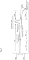
- the crystallization temperature here refers to the temperature at an exothermic peak during crystallization as the temperature decreases, which is observed in thermal analysis using differential scanning calorimetry (DSC) ("exothermic peak during crystallization" in Fig. 7 ).
- the melting point here refers to the temperature at an endothermic peak during fusion as the temperature increases, which is observed in thermal analysis using differential scanning calorimetry (DSC) ("endothermic peak during fusion” in Fig. 7 ).
- the temperature at this forming step S3 is suitably set in accordance with specifics of the resin material of the thermoplastic tube P.
- a polyamide resin such as nylon
- the temperature is 100°C or more and 200°C or less, preferably 120°C or more and 180°C or less, and more preferably 130°C or more and 170°C or less.
- the holding time is also suitably set in accordance with specifics of the resin material of the thermoplastic tube P.
- the holding time is 150 seconds or more, preferably 160 seconds or more and 600 seconds or less, and more preferably 180 seconds or more and 400 seconds or less.
- the temperature and holding time in the forming step described above should preferably be set with reference to the properties of the resin material constituting the thickest layer that affects the shape change most.
- the temperature is set to a level at least equal to or lower than the melting point of the resin material having the lowest melting point.
- the forming step S3 includes a step in which the thermoplastic tube P that has been bent is heated or held at the crystallization temperature or higher and the melting-point temperature or less by temperature control of the electric heaters 60 (step “S3a” in Fig. 7 ), and also a step in which the tube is gradually cooled down (step “S3b” in Fig. 7 ).
- step “S3a” in Fig. 7 ) the step of gradually decreasing the temperature of the thermoplastic tube P at the crystallization temperature or higher and the melting-point temperature or less is important (cooling step "S3b” in Fig. 7 ).
- the rate of decreasing the temperature in this cooling step S3b is suitably set in accordance with specifics of the resin material of the thermoplastic tube P.
- the temperature decrease rate is preferably 7°C/min or less, and more preferably 2°C/min or more and 5°C/min or less.
- the duration of the cooling step S3b is also suitably set in accordance with specifics of the resin material of the thermoplastic tube P.
- the duration is preferably 130 seconds or more, and more preferably 150 seconds or more and 300 seconds or less.
- Fig. 6(a) is a diagram illustrating execution of the step in which the thermoplastic tube P is heated or held at the crystallization temperature or higher and the melting-point temperature or lower (heating step "S3a” in Fig. 7 ) by switching on the electric heaters 60, or by repeatedly switching on and off the electric heaters 60, with the thermoplastic tube P being held after it has been bent by the forming molds 10, 20, 30, and 40.
- Fig. 6(b) is a diagram illustrating execution of the step in which the thermoplastic tube P is gradually cooled down at the crystallization temperature or higher and the melting-point temperature or less (cooling step "S3b" in Fig.
- thermoplastic tube P proceeds to the next cooling step S4 (see Fig. 7 ).
- this cooling step S4 the thermoplastic tube P after the previous forming step S3 is cooled down to a temperature below the glass-transition temperature, to solidify the bent shape.
- the cooling method is not limited to a particular one, and any method whereby the formed thermoplastic tube P is removed from the forming mold 1, and transferred to a simple-shaped fixing mold so that the tube is naturally cooled, may be adopted, for example.
- thermoplastic tube bending method With the thermoplastic tube bending method described above, the thermoplastic tube P heated with the residual heat of the forming mold 1 can be bent precisely when held between the forming molds 10, 20, 30, and 40.
- the thermoplastic tube P that has been bent then undergoes the forming process by the temperature control of the electric heaters 60 provided to the forming mold 1 in the state in which the tube is retained in shape in the forming mold 1.
- the temperature can therefore be raised quickly and controlled accurately, so that precise forming of the thermoplastic tube P is possible in a short time.
- thermoplastic tube P that has been bent is held at the crystallization temperature or higher and the melting-point temperature or less for a predetermined time by the temperature control of the electric heaters 60, accelerates crystallization of the thermoplastic tube P, which allows bending with little springback afterwards to be readily realized, and thermoplastic tubes with a good shape quality to be achieved.
- thermoplastic tube bending method according to the present invention has been described in detail above, it goes without saying that the present invention is not only applicable to the embodiment described above as one example here but also can be embodied as a method using forming molds and the like in other forms based on the same technical concept.
- the forming mold may be composed of three components, as illustrated in Fig. 8 .
- This forming mold 1 is configured such that the lower forming mold 30 of the Z-direction forming molds 30 and 40, which are clamped in the Z direction to bend the thermoplastic tube P in the Z direction, of the forming mold 1 according to the embodiment illustrated in Fig. 1 , is integrally attached to the plate surface of one forming mold 10 of the XY-plane forming molds 10 and 20 that are clamped in the X direction to bend the thermoplastic tube P in the XY plane, i.e., it is substantially made up of three components. Therefore the configuration is even simpler.
- this forming mold 1 involves only the clamping of the XY-plane forming molds 10 and 20 in the X direction and the clamping of the upper Z-direction forming mold 40 in the Z direction, so the operation control is made easier.
- the forming mold may also be the one illustrated in Fig. 9 .
- This forming mold 1 is configured as follows: the lower forming mold 30 of the Z-direction forming molds 30 and 40 of the forming mold 1 according to the embodiment illustrated in Fig. 1 is extended in the X direction and made thicker to serve as the base, this base-like lower Z-direction forming mold 30 being integrally attached to the plate surface of one forming mold 10 of the XY-plane forming molds 10 and 20.
- the other forming mold 20 of the XY-plane forming molds 10 and 20 has a lower end face curved in a shape conforming to that of the upper end face of the base-like lower Z-direction forming mold 30, and this XY-plane forming mold 20 with the curved lower end face is slid on the base-like lower Z-direction forming mold 30, so that the molds are clamped in the X direction.
- the forming mold 1 with such a configuration provides similar effects as those of the forming mold illustrated in Fig. 8 , and moreover, the base-like lower Z-direction forming mold 30 serves as the platform that supports the thermoplastic tube P being processed, which prevents the forming mold from biting into the thermoplastic tube P.
- Fig. 10 shows a forming mold composed of two components.
- This forming mold 1 is configured such that the lower forming mold 30 of the Z-direction forming molds 30 and 40 of the forming mold 1 according to the embodiment illustrated in Fig. 1 is integrally attached to the lower plate surface of one forming mold 10 of the XY-plane forming molds 10 and 20, and the upper forming mold 40 of the Z-direction forming molds 30 and 40 is integrally attached to the upper plate surface of the other forming mold 20 of the XY-plane forming molds 10 and 20, i.e., it is substantially made up of two components. Therefore the configuration is even simpler.
- This forming mold 1 is operated such that the other XY-plane forming mold 20 integrated with the upper Z-direction forming mold 40 is clamped in the X direction as indicated with the arrow in Fig. 10 , and then the XY-plane forming mold 20 is moved in the Z direction, and therefore the operation control is made even easier.
- the bending may be performed using a forming mold 100 that has a completely different design from that of the forming mold 1 described above, as illustrated in Fig. 11 and Fig. 12 .
- This forming mold 100 is made up of a pair of forming molds 110 and 120 that are clamped in the Z direction.
- the pair of forming molds 110 and 120 respectively include forming recesses 111 and 121, and guide parts 112 and 122 that guide the thermoplastic tube P into the forming recesses.
- the forming recesses 111 and 121 are each formed in a shape with a semi-circular cross section so that they define an elongated columnar cavity therebetween when the pair of forming molds are clamped for forming the thermoplastic tube P that is bent three dimensionally in X, Y, and Z directions.
- the guide parts 112 and 122 each extend outward in V-shape from both sides of the forming recesses with the semi-circular cross section.
- Temperature-controlled electric heaters 130 are embedded in respective base parts of the pair of forming molds 110 and 120.
- thermoplastic tube P to be processed can be readily set into the forming mold 100.
- the thermoplastic tube P After being set, as the pair of forming molds 110 and 120 are clamped, the thermoplastic tube P is gradually bent along the slopes of the guide parts 112 and 122 and slides into the forming recesses 111 and 121, i.e., the thermoplastic tube P is fitted into the forming recesses 111 and 121 as it is bent also in directions other than the Z direction that is the mold clamping direction.
- thermoplastic tube P When the forming mold 100 is completely closed, the thermoplastic tube P is entirely surrounded by the forming recesses 111 and 121 respectively formed on the pair of forming molds 110 and 120, and this way the thermoplastic tube P can be bent three dimensionally in the X, Y, and Z direction quickly and reliably.
- thermoplastic tubes with less springback can be obtained in a short time and safe manner, and the method is therefore widely applicable to the bending of thermoplastic tubes, pipes and hoses that are used in particular as car components or the like.
Landscapes
- Engineering & Computer Science (AREA)
- Mechanical Engineering (AREA)
- Physics & Mathematics (AREA)
- Health & Medical Sciences (AREA)
- Oral & Maxillofacial Surgery (AREA)
- Thermal Sciences (AREA)
- Shaping Of Tube Ends By Bending Or Straightening (AREA)
Description
- The present invention relates to a thermoplastic tube bending method, and more particularly to a thermoplastic tube bending method that suppresses springback after the bending.
- Bending processes performed in a heated atmosphere are well known as the method of bending a thermoplastic tube into a three-dimensionally bent form such as a fuel pipe that is a car component, for example.
- In a bending method that takes place in a heated atmosphere, a straight thermoplastic tube is fitted into a bending mold, this bending mold being then put into an atmosphere furnace with the temperature raised to a predetermined level, so as to heat the thermoplastic tube to be bent to conform to the mold and to form the same into a predetermined shape.
- Such a bending method using a heated atmosphere requires a considerably long time (about 20 minutes) since when the bending mold is put into the atmosphere furnace until when a predetermined forming temperature (about 165°C) is reached, and is poor in energy efficiency and productivity.
- Accordingly, there have been developed techniques that use infrared radiation for the heating of thermoplastic tubes (for example, PTL 1). Another heating method that has been considered causes a high-temperature, high-pressure fluid (steam) to flow into the thermoplastic tube (for example, PTL 2).
Such prior art is disclosed in theJapanese Patent Application Publication No. H4-267136 Japanese Patent Application Publication No. 2001-9902
The documentUS 6 228 307 B1 discloses a method for bending a component made of thermoplastic material comprising: arranging the component in a holding device; shaping the component at a first temperature into a shaped condition by means of at least two tools including a first tool and a second tool by moving the first tool towards the second tool; causing the first and second tools to hold the component in its shaped condition; and after shaping the component and while the first and second tools hold the component in its shaped condition, heating the component above the first temperature to about the softening point of the plastic by a heating unit associated with at least one of the first and second tools. - However, with the former method that uses infrared for the heating, the quality in terms of, for instance, shape can hardly be ensured because of the unfeasibility to heat the entire tube uniformly due to inevitable unevenness in the infrared irradiation. The latter heating method that uses steam may have safety issues entailing the risk of burn injuries in the event of steam leakage.
- The present invention has been made in view of the problems encountered in the background art as described above, an object thereof being to provide a thermoplastic tube bending method that suppresses springback after the processing by a highly safe and short-time bending process and that can produce a thermoplastic tube with a high shape quality.
- To achieve the above object, the present invention provides a thermoplastic tube bending method as set forth in appended claims 1-4.
- With the thermoplastic tube bending method according to the present invention as claimed, the forming process is performed by the temperature control of the electric heater provided to the forming mold, so that the temperature can be raised quickly and controlled safely. Therefore, the thermoplastic tube bending process can be performed in a short time and highly safely, without requiring large scale equipment such as a furnace.
- The forming step, in particular, where the thermoplastic tube that has been bent is held at the crystallization temperature or higher and a melting-point temperature or lower for a predetermined time by the temperature control of the electric heater, accelerates crystallization of the thermoplastic tube, which allows bending with little springback afterwards to be readily realized, so that thermoplastic tubes with a good shape quality can be achieved.
-
- [
Fig. 1 ]
Fig. 1 is an exploded perspective view of a conceptual illustration of one example of a forming mold used in a thermoplastic tube bending method according to the present invention. - [
Fig. 2 ]
Fig. 2 is a conceptual cross-sectional view of major parts of the forming mold shown inFig. 1 . - [
Fig. 3 ]
Fig. 3 is a perspective view of a conceptual illustration of one embodiment of a preheating process in the thermoplastic tube bending method according to the present invention. - [
Fig. 4 ]
Fig. 4 is a perspective view of a conceptual illustration of one embodiment of a bending process in the thermoplastic tube bending method according to the present invention, (a) being a diagram illustrating a step in which a thermoplastic tube is set into the forming mold, and (b) being a diagram illustrating a bending step in which the thermoplastic tube is bent in X and Y directions. - [
Fig. 5 ]
Fig. 5 is a perspective view of a conceptual illustration of one embodiment of a bending process in the thermoplastic tube bending method according to the present invention, (a) being a diagram illustrating a step in which a lower Z-direction forming mold is set, and (b) being a diagram illustrating a bending step in which the thermoplastic tube is bent in the Z direction. - [
Fig. 6 ]
Fig. 6 is a perspective view of a conceptual illustration of one embodiment of a forming process in the thermoplastic tube bending method according to the present invention, (a) being a diagram illustrating a step in which, with a thermoplastic tube that has been bent in the forming mold being held, the temperature is raised (to heat the tube), and (b) being a diagram illustrating a step in which, with only the Z-direction forming mold being opened, the thermoplastic tube that has been bent by the XY-plane forming molds is held, and the temperature is gradually lowered (to cool down the tube). - [
Fig. 7 ]
Fig. 7 is a diagram illustrating DSC curves of one embodiment of various steps in the thermoplastic tube bending method according to the present invention. - [
Fig. 8 ]
Fig. 8 is an exploded perspective view of a conceptual illustration of a variation example of the forming mold used in the thermoplastic tube bending method according to the present invention. - [
Fig. 9 ]
Fig. 9 is an exploded perspective view of a conceptual illustration of another variation example of the forming mold used in the thermoplastic tube bending method according to the present invention. - [
Fig. 10 ]
Fig. 10 is an exploded perspective view of a conceptual illustration of yet another variation example of the forming mold used in the thermoplastic tube bending method according to the present invention. - [
Fig. 11 ]
Fig. 11 is an exploded perspective view of a conceptual illustration of another example of the forming mold used in the thermoplastic tube bending method according to the present invention. - [
Fig. 12 ]
Fig. 12 is a conceptual cross-sectional view of major parts of the forming mold shown inFig. 11 . - One embodiment of a thermoplastic tube bending method according to the present invention will be hereinafter described in detail. Note, the following description of the preferred embodiment is essentially merely an illustration and not intended to limit the present invention to this embodiment.
- The bending method according to the present invention is applicable to thermoplastic tubes, and can be applied to various tubes, hoses, and pipes made of thermoplastic resin.
- The thermoplastic tube is a tube with a circular section having the inside and outside diameters substantially uniform from one end to the other and can be single layered or multilayered. The thermoplastic tube may have an outside diameter of about 4 to 40 mm and a thickness of about 0.5 to 3 mm, and may be used, for example, for fluid communication between a fuel injection pipe and a fuel tank of a car, or as a connection pipe for feeding fuel to the engine, cooling water pipe, a pipe that leads to a heater unit, an air hose, and the like.
- Examples of resin materials that constitute the thermoplastic tube are, for example, polyamide resins, polyethylene resins, polypropylene resins, polyethylene terephthalate resins, fluorocarbon resins, and the like. The tube is produced from these resin materials by extrusion forming. Several resin materials may be extruded in layers so that the tube has a multilayered structure. Among the resins listed above, polyamide resin has excellent resistance to chemicals and heat, and therefore is suitable as a material for the tube used as a fuel pipe.
- The present invention relates to a method of bending the thermoplastic tubes described above, which includes a step of preheating a thermoplastic tube, a step of bending the preheated thermoplastic tube, and a step of forming the bent thermoplastic tube.
- The present invention uses a forming mold, which may be the one illustrated in
Fig. 1 andFig. 2 , for example. - The illustrated forming
mold 1 is made up of XY-plane forming molds direction forming molds thermal insulation walls 50 that surround the outside of these forming molds. The Z-direction forming molds electric heater 60. - The XY-
plane forming molds surface surfaces - This pair of XY-
plane forming molds opposite forming surfaces - The pair of XY-
plane forming molds - The Z-
direction forming molds direction forming molds surfaces plane forming molds - The opposing distal end surfaces of this pair of Z-
direction forming molds recesses Fig. 2 for forming the thermoplastic tube P bent three-dimensionally in the X, Y, and Z directions. - The pair of Z-
direction forming molds - The pair of XY-
plane forming molds direction forming molds - The
thermal insulation walls 50 mentioned above may be any walls that cover the surroundings of the formingmolds thermal insulation walls 50 made up of a plurality of plate members to compactly cover the surroundings of all the forming molds as in the illustrated embodiment are preferable from the viewpoints of material costs, installation space, and energy efficiency. The material that forms thethermal insulation walls 50 is not limited to a particular one. The walls may be made of a material that is heat-insulating itself, such as sintered quartz, asbestos, fireproof heat-insulating brick, calcium silicate and the like, or plate-like members layered to form gaps therein to provide heat insulation. - The
electric heaters 60 provided to each of the pair of Z-direction forming molds direction forming molds recesses thermal insulation walls 50 described above. - With the thermoplastic tube bending method according to the present invention, the thermoplastic tube P is bent through temperature control in various steps as described below and as shown in
Fig. 7 , for example, using the formingmold 1 described above. - First, as illustrated in
Fig. 3 , a straight thermoplastic tube P is set in the formingmold 1, and the upperthermal insulation wall 50 is closed. - The thermoplastic tube P set in the forming
mold 1 is preheated to a predetermined temperature by being heated from all around with the residual heat of each of the formingmolds thermal insulation walls 50. This preheating step S1 (seeFig. 7 ) is a step of softening the straight thermoplastic tube P to facilitate the following bending process using the formingmold 1 with good precision, and it is preferable to heat the thermoplastic tube P to nearly the glass-transition temperature. This preheating temperature is suitably set in accordance with specifics of the resin material of the thermoplastic tube P. When a polyamide resin such as nylon is employed as the resin material, for example, the thermoplastic tube P need only be heated to about 30°C to 40°C. In a configuration where it is hard to preheat the tube up to a predetermined temperature with only the residual heat of the formingmolds electric heaters 60 embedded in the forming mold may be powered to assist the heating. - Next, the preheated thermoplastic tube P is bent, by operating the forming
molds Fig. 4 andFig. 5 . In this bending step S2 (seeFig. 7 ), first, the XY-plane forming molds surfaces plane forming molds Fig. 4(b) ). Next, the lower formingmold 30 of the pair of Z-direction forming molds direction forming mold 30 inside the cavity defined between the opposite formingsurfaces plane forming molds 10 and 20 (seeFig. 5(a) ). Next, the upper Z-direction forming mold 40 is clamped in the Z direction by an actuator (not shown) to sandwich the thermoplastic tube P between the formingrecesses direction forming molds Fig. 5(b) ). The operations described above may be carried out substantially at the same time to bend the thermoplastic tube P by the formingmolds electric heaters 60 embedded in the forming mold may be powered to raise the temperature of the thermoplastic tube P while performing the bending process. - Next, the bent thermoplastic tube P undergoes a forming step, wherein the tube is heated in a state where its shape is retained in the forming
mold 1 as illustrated inFig. 6 . This forming step S3 (seeFig. 7 ) is performed with an aim to reduce the springback after the bending of the thermoplastic tube P that has been bent. The present invention is characterized in that this forming step S3 is performed by temperature control of theelectric heaters 60 embedded in the formingmold 1. This, with theelectric heaters 60 capable of accurate and rapid temperature control, allows for efficient, safe, and precise forming of the thermoplastic tube P in a short time. - In the forming step S3, with an aim to reduce the springback after the bending, the thermoplastic tube P that has been bent is held at the crystallization temperature or higher and the melting-point temperature or less for a predetermined time by the temperature control of the
electric heaters 60. This accelerates crystallization of the thermoplastic tube P, so that the resultant thermoplastic tube P shows less springback after the bending. The crystallization temperature here refers to the temperature at an exothermic peak during crystallization as the temperature decreases, which is observed in thermal analysis using differential scanning calorimetry (DSC) ("exothermic peak during crystallization" inFig. 7 ). The melting point here refers to the temperature at an endothermic peak during fusion as the temperature increases, which is observed in thermal analysis using differential scanning calorimetry (DSC) ("endothermic peak during fusion" inFig. 7 ). - The temperature at this forming step S3 is suitably set in accordance with specifics of the resin material of the thermoplastic tube P. When a polyamide resin such as nylon is employed as the resin material, for example, the temperature is 100°C or more and 200°C or less, preferably 120°C or more and 180°C or less, and more preferably 130°C or more and 170°C or less. The holding time is also suitably set in accordance with specifics of the resin material of the thermoplastic tube P. When a polyamide resin such as nylon is employed as the resin material, for example, the holding time is 150 seconds or more, preferably 160 seconds or more and 600 seconds or less, and more preferably 180 seconds or more and 400 seconds or less.
- When the thermoplastic tube P is made of different resin materials and has a multilayered structure, the temperature and holding time in the forming step described above should preferably be set with reference to the properties of the resin material constituting the thickest layer that affects the shape change most. The temperature is set to a level at least equal to or lower than the melting point of the resin material having the lowest melting point.
- The forming step S3 includes a step in which the thermoplastic tube P that has been bent is heated or held at the crystallization temperature or higher and the melting-point temperature or less by temperature control of the electric heaters 60 (step "S3a" in
Fig. 7 ), and also a step in which the tube is gradually cooled down (step "S3b" inFig. 7 ). In terms of reducing springback after the bending by accelerating crystallization in a short time, in particular, the step of gradually decreasing the temperature of the thermoplastic tube P at the crystallization temperature or higher and the melting-point temperature or less is important (cooling step "S3b" inFig. 7 ). The rate of decreasing the temperature in this cooling step S3b is suitably set in accordance with specifics of the resin material of the thermoplastic tube P. When a polyamide resin such as nylon is employed as the resin material, for example, the temperature decrease rate is preferably 7°C/min or less, and more preferably 2°C/min or more and 5°C/min or less. The duration of the cooling step S3b is also suitably set in accordance with specifics of the resin material of the thermoplastic tube P. When a polyamide resin such as nylon is employed as the resin material, for example, the duration is preferably 130 seconds or more, and more preferably 150 seconds or more and 300 seconds or less. -
Fig. 6(a) is a diagram illustrating execution of the step in which the thermoplastic tube P is heated or held at the crystallization temperature or higher and the melting-point temperature or lower (heating step "S3a" inFig. 7 ) by switching on theelectric heaters 60, or by repeatedly switching on and off theelectric heaters 60, with the thermoplastic tube P being held after it has been bent by the formingmolds Fig. 6(b) is a diagram illustrating execution of the step in which the thermoplastic tube P is gradually cooled down at the crystallization temperature or higher and the melting-point temperature or less (cooling step "S3b" inFig. 7 ) by switching off theelectric heaters 60, or by repeatedly switching on and off theelectric heaters 60, with the Z-direction forming molds plane forming molds - Next, the formed thermoplastic tube P proceeds to the next cooling step S4 (see
Fig. 7 ). In this cooling step S4, the thermoplastic tube P after the previous forming step S3 is cooled down to a temperature below the glass-transition temperature, to solidify the bent shape. The cooling method is not limited to a particular one, and any method whereby the formed thermoplastic tube P is removed from the formingmold 1, and transferred to a simple-shaped fixing mold so that the tube is naturally cooled, may be adopted, for example. - With the thermoplastic tube bending method described above, the thermoplastic tube P heated with the residual heat of the forming
mold 1 can be bent precisely when held between the formingmolds electric heaters 60 provided to the formingmold 1 in the state in which the tube is retained in shape in the formingmold 1. The temperature can therefore be raised quickly and controlled accurately, so that precise forming of the thermoplastic tube P is possible in a short time. The forming step, in particular, where the thermoplastic tube P that has been bent is held at the crystallization temperature or higher and the melting-point temperature or less for a predetermined time by the temperature control of theelectric heaters 60, accelerates crystallization of the thermoplastic tube P, which allows bending with little springback afterwards to be readily realized, and thermoplastic tubes with a good shape quality to be achieved. - While the thermoplastic tube bending method according to the present invention has been described in detail above, it goes without saying that the present invention is not only applicable to the embodiment described above as one example here but also can be embodied as a method using forming molds and the like in other forms based on the same technical concept.
- For example, the forming mold may be composed of three components, as illustrated in
Fig. 8 . This formingmold 1 is configured such that the lower formingmold 30 of the Z-direction forming molds mold 1 according to the embodiment illustrated inFig. 1 , is integrally attached to the plate surface of one formingmold 10 of the XY-plane forming molds - The operation of this forming
mold 1 involves only the clamping of the XY-plane forming molds direction forming mold 40 in the Z direction, so the operation control is made easier. - The forming mold may also be the one illustrated in
Fig. 9 . This formingmold 1 is configured as follows: the lower formingmold 30 of the Z-direction forming molds mold 1 according to the embodiment illustrated inFig. 1 is extended in the X direction and made thicker to serve as the base, this base-like lower Z-direction forming mold 30 being integrally attached to the plate surface of one formingmold 10 of the XY-plane forming molds mold 20 of the XY-plane forming molds direction forming mold 30, and this XY-plane forming mold 20 with the curved lower end face is slid on the base-like lower Z-direction forming mold 30, so that the molds are clamped in the X direction. - The forming
mold 1 with such a configuration provides similar effects as those of the forming mold illustrated inFig. 8 , and moreover, the base-like lower Z-direction forming mold 30 serves as the platform that supports the thermoplastic tube P being processed, which prevents the forming mold from biting into the thermoplastic tube P. -
Fig. 10 shows a forming mold composed of two components. This formingmold 1 is configured such that the lower formingmold 30 of the Z-direction forming molds mold 1 according to the embodiment illustrated inFig. 1 is integrally attached to the lower plate surface of one formingmold 10 of the XY-plane forming molds mold 40 of the Z-direction forming molds mold 20 of the XY-plane forming molds - This forming
mold 1 is operated such that the other XY-plane forming mold 20 integrated with the upper Z-direction forming mold 40 is clamped in the X direction as indicated with the arrow inFig. 10 , and then the XY-plane forming mold 20 is moved in the Z direction, and therefore the operation control is made even easier. - Further, the bending may be performed using a forming
mold 100 that has a completely different design from that of the formingmold 1 described above, as illustrated inFig. 11 andFig. 12 . This formingmold 100 is made up of a pair of formingmolds molds recesses parts recesses guide parts electric heaters 130 are embedded in respective base parts of the pair of formingmolds - Since this forming
mold 100 has theguide parts mold 100. After being set, as the pair of formingmolds guide parts recesses recesses mold 100 is completely closed, the thermoplastic tube P is entirely surrounded by the formingrecesses molds - With the thermoplastic tube bending method according to the present invention, thermoplastic tubes with less springback can be obtained in a short time and safe manner, and the method is therefore widely applicable to the bending of thermoplastic tubes, pipes and hoses that are used in particular as car components or the like.
-
- 1 Forming mold
- 10, 20 XY-plane forming mold
- 11, 21 Forming surface
- 30, 40 Z-direction forming mold
- 31, 41 Forming recess
- 50 Thermal insulation wall
- 60 Electric heater
- 100 Forming mold
- 110, 120 Pair of forming molds clamped in the Z direction
- 111, 121 Forming recess
- 112, 122 Guide part
- 130 Electric heater
- P Thermoplastic tube
- S1 Preheating step
- S2 Bending step
- S3 Forming step
- S4 Cooling step
Claims (4)
- A thermoplastic tube bending method comprising:a step (S1) of preheating a thermoplastic tube (P);a step (S2) of bending the preheated thermoplastic tube by using a forming mold (1); anda step (S3) of forming the bent thermoplastic tube (P),characterized in thatthe forming step (S3) is performed by temperature control of an electric heater (60) provided to the forming mold (1),wherein the forming mold (1) comprises XY-plane forming molds (10, 20) that are clamped in an X direction to bend the thermoplastic tube (P) in an XY plane, and Z-direction forming molds (30, 40) that are clamped in a Z direction to bend the thermoplastic tube (P) in the Z direction, and whereinboth of the forming molds (10, 20, 30, 40), when clamped, together define a cavity therebetween for forming the thermoplastic tube (P) bent three-dimensionally in X, Y, and Z directions, andwherein the Z-direction forming molds (30, 40) are a pair of forming molds clamped in the Z direction and having opposing distal end surfaces each formed with a forming recess (31, 41), which, when the forming molds (30, 40) are clamped, define the cavity therebetween for forming the thermoplastic tube bent three-dimensionally in X, Y, and Z directions, and wherein the electric heater (60) is embedded in the Z-direction forming molds (30, 40).
- The thermoplastic tube bending method according to claim 1, wherein, in the forming step (S3), the bent thermoplastic tube (P) is held at a crystallization temperature or higher and a melting-point temperature or lower for a predetermined time by temperature control of the electric heater (60).
- The thermoplastic tube bending method according to claim 1 or 2, wherein the forming step includes a step of gradually cooling the bent thermoplastic tube (P) at a crystallization temperature or higher and a melting-point temperature or lower by temperature control of the electric heater (60).
- The thermoplastic tube bending method according to any one of claims 1 to 3, wherein the preheating step is performed with residual heat of the forming mold (1).
Applications Claiming Priority (2)
| Application Number | Priority Date | Filing Date | Title |
|---|---|---|---|
| JP2019145893A JP7273652B2 (en) | 2019-08-08 | 2019-08-08 | Method for bending thermoplastic resin tube |
| PCT/JP2020/015461 WO2021024549A1 (en) | 2019-08-08 | 2020-04-06 | Thermoplastic resin tube bending method |
Publications (3)
| Publication Number | Publication Date |
|---|---|
| EP3950270A1 EP3950270A1 (en) | 2022-02-09 |
| EP3950270A4 EP3950270A4 (en) | 2022-12-28 |
| EP3950270B1 true EP3950270B1 (en) | 2024-10-23 |
Family
ID=74503427
Family Applications (1)
| Application Number | Title | Priority Date | Filing Date |
|---|---|---|---|
| EP20850385.4A Active EP3950270B1 (en) | 2019-08-08 | 2020-04-06 | Thermoplastic resin tube bending method |
Country Status (9)
| Country | Link |
|---|---|
| US (1) | US12325175B2 (en) |
| EP (1) | EP3950270B1 (en) |
| JP (1) | JP7273652B2 (en) |
| KR (1) | KR102923392B1 (en) |
| CN (1) | CN113939390B (en) |
| HU (1) | HUE069493T2 (en) |
| MX (1) | MX2021012828A (en) |
| TW (1) | TWI849105B (en) |
| WO (1) | WO2021024549A1 (en) |
Families Citing this family (1)
| Publication number | Priority date | Publication date | Assignee | Title |
|---|---|---|---|---|
| BE1032890B1 (en) * | 2024-08-05 | 2026-04-14 | Safran Aero Boosters Sa | Bending device for an elongated workpiece |
Family Cites Families (22)
| Publication number | Priority date | Publication date | Assignee | Title |
|---|---|---|---|---|
| BE461379A (en) * | 1941-12-19 | |||
| JPS5959417A (en) * | 1982-09-30 | 1984-04-05 | Toyoda Gosei Co Ltd | Bending processing of synthetic resin hose |
| JPS59164711U (en) * | 1983-04-19 | 1984-11-05 | 株式会社 潤工社 | Molding equipment for synthetic resin tubes and hoses |
| GB9024619D0 (en) | 1990-11-13 | 1991-01-02 | Mckechnie Plastics Ltd | Thermoplastic hoses and tubes |
| US5422048A (en) * | 1992-09-30 | 1995-06-06 | Tokai Rubber Industries, Ltd. | Method of producing a bent resin tube |
| DE4329965C1 (en) * | 1993-09-04 | 1994-10-13 | Franz Schulte | Method of bending plastics pipes having a number of bends lying one behind the other |
| DE19607069A1 (en) * | 1996-02-24 | 1997-08-28 | Braun Ag | Method and device for bending a component made of a thermoplastic and component itself |
| JP3200579B2 (en) * | 1997-11-18 | 2001-08-20 | 株式会社アイコー | Bending machine for thermoplastic synthetic resin plate |
| JP2001009902A (en) | 1999-04-30 | 2001-01-16 | Piolax Inc | Production of bent resin hose |
| US20040258789A1 (en) * | 2003-06-19 | 2004-12-23 | Phillips James D. | Tube bending apparatus and method |
| JP4642629B2 (en) * | 2004-10-20 | 2011-03-02 | 株式会社早川製作所 | High-speed bending method of resin tube and three-dimensional bending mold used in this method |
| CN100551674C (en) * | 2004-10-20 | 2009-10-21 | 株式会社早川制作所 | High-speed bending method of resin pipe and three-dimensional bending die used in the method |
| KR101332965B1 (en) * | 2011-11-21 | 2013-11-25 | 인지컨트롤스 주식회사 | plastic structure unit and joining method therefor |
| US11524443B2 (en) * | 2016-02-24 | 2022-12-13 | Mitsui Chemicals, Inc. | Process for producing shaped film |
| JP2017154280A (en) * | 2016-02-29 | 2017-09-07 | 住友理工株式会社 | Method for manufacturing bent-pipe-like resin tube |
| JP2017193094A (en) * | 2016-04-20 | 2017-10-26 | 三菱電機株式会社 | Flexure processing device of thermoplastic resin tube |
| JP6809836B2 (en) * | 2016-08-03 | 2021-01-06 | 倉敷化工株式会社 | Resin tube bending method |
| JP6809841B2 (en) * | 2016-08-10 | 2021-01-06 | 倉敷化工株式会社 | Resin tube molding device and resin tube molding method using the molding device |
| JP7002364B2 (en) | 2018-03-01 | 2022-01-20 | 三桜工業株式会社 | Bending mold |
| EP3593975A1 (en) * | 2018-07-09 | 2020-01-15 | MSV SYSTEMS CZ s.r.o. | Method of shaping products made of hdpe or pa, particularly spatial shaping of hdpe or pa tubes, and a device for performing it |
| CN109109300A (en) * | 2018-09-26 | 2019-01-01 | 天津市塑料研究所有限公司 | Poly- carbon pipe apparatus for bending and operating method |
| US20200406508A1 (en) * | 2019-06-27 | 2020-12-31 | GM Global Technology Operations LLC | Thermoregulated mold and method of fabricating the same |
-
2019
- 2019-08-08 JP JP2019145893A patent/JP7273652B2/en active Active
-
2020
- 2020-04-06 CN CN202080039774.9A patent/CN113939390B/en active Active
- 2020-04-06 EP EP20850385.4A patent/EP3950270B1/en active Active
- 2020-04-06 US US17/629,941 patent/US12325175B2/en active Active
- 2020-04-06 KR KR1020217041985A patent/KR102923392B1/en active Active
- 2020-04-06 HU HUE20850385A patent/HUE069493T2/en unknown
- 2020-04-06 MX MX2021012828A patent/MX2021012828A/en unknown
- 2020-04-06 WO PCT/JP2020/015461 patent/WO2021024549A1/en not_active Ceased
- 2020-04-15 TW TW109112567A patent/TWI849105B/en active
Also Published As
| Publication number | Publication date |
|---|---|
| CN113939390A (en) | 2022-01-14 |
| JP2021024229A (en) | 2021-02-22 |
| KR102923392B1 (en) | 2026-02-06 |
| EP3950270A1 (en) | 2022-02-09 |
| WO2021024549A1 (en) | 2021-02-11 |
| CN113939390B (en) | 2024-09-13 |
| TWI849105B (en) | 2024-07-21 |
| US12325175B2 (en) | 2025-06-10 |
| HUE069493T2 (en) | 2025-03-28 |
| TW202108337A (en) | 2021-03-01 |
| JP7273652B2 (en) | 2023-05-15 |
| KR20220044245A (en) | 2022-04-07 |
| EP3950270A4 (en) | 2022-12-28 |
| MX2021012828A (en) | 2021-11-25 |
| US20220288840A1 (en) | 2022-09-15 |
Similar Documents
| Publication | Publication Date | Title |
|---|---|---|
| US11926093B2 (en) | Methods and apparatus for embedding heating circuits into articles made by additive manufacturing and articles made therefrom | |
| US10189214B2 (en) | Freespace composite manufacturing process and device | |
| RU2566104C2 (en) | Device and method for forming by titanium drawing | |
| KR20120123350A (en) | Method for producing continuous-fibre-reinforced moulded parts from thermoplastic plastics and motor vehicle moulded part | |
| US10464263B2 (en) | Heat welding apparatus for combining plastic fuel tank and plastic parts and method of combining plastic fuel tank and plastic parts using the apparatus | |
| US12325175B2 (en) | Thermoplastic tube bending method | |
| RU2542948C2 (en) | Device and method for drawing with heating | |
| CN108273903A (en) | Utilize the method and apparatus of the contact pilotage progressive molding prototype part of heating | |
| WO2020165307A1 (en) | Temperature control system for rotational moulding technology | |
| US6328842B1 (en) | Machine for welding hollow articles and process for welding these articles | |
| CN109501313B (en) | A kind of continuous fiber reinforced thermoplastic composite material non-isothermal forming device and process | |
| KR20090099482A (en) | Molding method of blow molded article, blow molded article and apparatus for manufacturing same | |
| US11660824B2 (en) | Apparatus and method for establishing or for separating a connection having material continuity or having material continuity and shape matching of at least one metal or ceramic component and of a component formed from or by a thermoplastic polymer | |
| CN110667120A (en) | Device and method for producing a component consisting of a plurality of plastic moulded parts welded to one another | |
| CN110171083B (en) | Method and heating device for heating a semifinished product | |
| JP2000043144A (en) | Machine and method for fusing hollow object | |
| KR102024790B1 (en) | Inosculating device of Expanded Polypropylene molding article and Inosculating methods | |
| JP6781704B2 (en) | Thermoplastic material heat forming method and implementation equipment | |
| US20100307732A1 (en) | Method and apparatus for controlling heating and cooling of transfer unit in precision hot press apparatus | |
| EP4371726A1 (en) | Molding device and molding method | |
| CN113351878B (en) | Induction heating coil manufacturing method | |
| CN112672836A (en) | Mould with heat conduction flange | |
| Murata et al. | Development of heating and cooling injection mold with far-infrared radiation heater | |
| KR20250072704A (en) | Heat treatment of 3D printed parts | |
| Kupzik | Robotic Swing Folding of three-dimensional UD-tape-based Reinforcement Structures |
Legal Events
| Date | Code | Title | Description |
|---|---|---|---|
| STAA | Information on the status of an ep patent application or granted ep patent |
Free format text: STATUS: THE INTERNATIONAL PUBLICATION HAS BEEN MADE |
|
| PUAI | Public reference made under article 153(3) epc to a published international application that has entered the european phase |
Free format text: ORIGINAL CODE: 0009012 |
|
| STAA | Information on the status of an ep patent application or granted ep patent |
Free format text: STATUS: REQUEST FOR EXAMINATION WAS MADE |
|
| 17P | Request for examination filed |
Effective date: 20211103 |
|
| AK | Designated contracting states |
Kind code of ref document: A1 Designated state(s): AL AT BE BG CH CY CZ DE DK EE ES FI FR GB GR HR HU IE IS IT LI LT LU LV MC MK MT NL NO PL PT RO RS SE SI SK SM TR |
|
| DAV | Request for validation of the european patent (deleted) | ||
| DAX | Request for extension of the european patent (deleted) | ||
| A4 | Supplementary search report drawn up and despatched |
Effective date: 20221124 |
|
| RIC1 | Information provided on ipc code assigned before grant |
Ipc: B29C 53/08 20060101AFI20221118BHEP |
|
| GRAP | Despatch of communication of intention to grant a patent |
Free format text: ORIGINAL CODE: EPIDOSNIGR1 |
|
| STAA | Information on the status of an ep patent application or granted ep patent |
Free format text: STATUS: GRANT OF PATENT IS INTENDED |
|
| INTG | Intention to grant announced |
Effective date: 20240607 |
|
| GRAS | Grant fee paid |
Free format text: ORIGINAL CODE: EPIDOSNIGR3 |
|
| GRAA | (expected) grant |
Free format text: ORIGINAL CODE: 0009210 |
|
| STAA | Information on the status of an ep patent application or granted ep patent |
Free format text: STATUS: THE PATENT HAS BEEN GRANTED |
|
| AK | Designated contracting states |
Kind code of ref document: B1 Designated state(s): AL AT BE BG CH CY CZ DE DK EE ES FI FR GB GR HR HU IE IS IT LI LT LU LV MC MK MT NL NO PL PT RO RS SE SI SK SM TR |
|
| REG | Reference to a national code |
Ref country code: GB Ref legal event code: FG4D |
|
| REG | Reference to a national code |
Ref country code: CH Ref legal event code: EP |
|
| REG | Reference to a national code |
Ref country code: DE Ref legal event code: R096 Ref document number: 602020040048 Country of ref document: DE |
|
| REG | Reference to a national code |
Ref country code: IE Ref legal event code: FG4D |
|
| REG | Reference to a national code |
Ref country code: LT Ref legal event code: MG9D |
|
| REG | Reference to a national code |
Ref country code: NL Ref legal event code: MP Effective date: 20241023 |
|
| REG | Reference to a national code |
Ref country code: AT Ref legal event code: MK05 Ref document number: 1734501 Country of ref document: AT Kind code of ref document: T Effective date: 20241023 |
|
| PG25 | Lapsed in a contracting state [announced via postgrant information from national office to epo] |
Ref country code: NL Free format text: LAPSE BECAUSE OF FAILURE TO SUBMIT A TRANSLATION OF THE DESCRIPTION OR TO PAY THE FEE WITHIN THE PRESCRIBED TIME-LIMIT Effective date: 20241023 |
|
| REG | Reference to a national code |
Ref country code: HU Ref legal event code: AG4A Ref document number: E069493 Country of ref document: HU |
|
| PG25 | Lapsed in a contracting state [announced via postgrant information from national office to epo] |
Ref country code: NL Free format text: LAPSE BECAUSE OF FAILURE TO SUBMIT A TRANSLATION OF THE DESCRIPTION OR TO PAY THE FEE WITHIN THE PRESCRIBED TIME-LIMIT Effective date: 20241023 |
|
| PG25 | Lapsed in a contracting state [announced via postgrant information from national office to epo] |
Ref country code: IS Free format text: LAPSE BECAUSE OF FAILURE TO SUBMIT A TRANSLATION OF THE DESCRIPTION OR TO PAY THE FEE WITHIN THE PRESCRIBED TIME-LIMIT Effective date: 20250223 Ref country code: HR Free format text: LAPSE BECAUSE OF FAILURE TO SUBMIT A TRANSLATION OF THE DESCRIPTION OR TO PAY THE FEE WITHIN THE PRESCRIBED TIME-LIMIT Effective date: 20241023 Ref country code: PT Free format text: LAPSE BECAUSE OF FAILURE TO SUBMIT A TRANSLATION OF THE DESCRIPTION OR TO PAY THE FEE WITHIN THE PRESCRIBED TIME-LIMIT Effective date: 20250224 |
|
| PG25 | Lapsed in a contracting state [announced via postgrant information from national office to epo] |
Ref country code: FI Free format text: LAPSE BECAUSE OF FAILURE TO SUBMIT A TRANSLATION OF THE DESCRIPTION OR TO PAY THE FEE WITHIN THE PRESCRIBED TIME-LIMIT Effective date: 20241023 |
|
| PG25 | Lapsed in a contracting state [announced via postgrant information from national office to epo] |
Ref country code: BG Free format text: LAPSE BECAUSE OF FAILURE TO SUBMIT A TRANSLATION OF THE DESCRIPTION OR TO PAY THE FEE WITHIN THE PRESCRIBED TIME-LIMIT Effective date: 20241023 |
|
| PG25 | Lapsed in a contracting state [announced via postgrant information from national office to epo] |
Ref country code: ES Free format text: LAPSE BECAUSE OF FAILURE TO SUBMIT A TRANSLATION OF THE DESCRIPTION OR TO PAY THE FEE WITHIN THE PRESCRIBED TIME-LIMIT Effective date: 20241023 |
|
| PG25 | Lapsed in a contracting state [announced via postgrant information from national office to epo] |
Ref country code: NO Free format text: LAPSE BECAUSE OF FAILURE TO SUBMIT A TRANSLATION OF THE DESCRIPTION OR TO PAY THE FEE WITHIN THE PRESCRIBED TIME-LIMIT Effective date: 20250123 |
|
| PG25 | Lapsed in a contracting state [announced via postgrant information from national office to epo] |
Ref country code: LV Free format text: LAPSE BECAUSE OF FAILURE TO SUBMIT A TRANSLATION OF THE DESCRIPTION OR TO PAY THE FEE WITHIN THE PRESCRIBED TIME-LIMIT Effective date: 20241023 Ref country code: GR Free format text: LAPSE BECAUSE OF FAILURE TO SUBMIT A TRANSLATION OF THE DESCRIPTION OR TO PAY THE FEE WITHIN THE PRESCRIBED TIME-LIMIT Effective date: 20250124 Ref country code: AT Free format text: LAPSE BECAUSE OF FAILURE TO SUBMIT A TRANSLATION OF THE DESCRIPTION OR TO PAY THE FEE WITHIN THE PRESCRIBED TIME-LIMIT Effective date: 20241023 |
|
| PG25 | Lapsed in a contracting state [announced via postgrant information from national office to epo] |
Ref country code: PL Free format text: LAPSE BECAUSE OF FAILURE TO SUBMIT A TRANSLATION OF THE DESCRIPTION OR TO PAY THE FEE WITHIN THE PRESCRIBED TIME-LIMIT Effective date: 20241023 |
|
| PG25 | Lapsed in a contracting state [announced via postgrant information from national office to epo] |
Ref country code: RS Free format text: LAPSE BECAUSE OF FAILURE TO SUBMIT A TRANSLATION OF THE DESCRIPTION OR TO PAY THE FEE WITHIN THE PRESCRIBED TIME-LIMIT Effective date: 20250123 |
|
| PG25 | Lapsed in a contracting state [announced via postgrant information from national office to epo] |
Ref country code: SM Free format text: LAPSE BECAUSE OF FAILURE TO SUBMIT A TRANSLATION OF THE DESCRIPTION OR TO PAY THE FEE WITHIN THE PRESCRIBED TIME-LIMIT Effective date: 20241023 |
|
| PGFP | Annual fee paid to national office [announced via postgrant information from national office to epo] |
Ref country code: DE Payment date: 20250305 Year of fee payment: 6 |
|
| PG25 | Lapsed in a contracting state [announced via postgrant information from national office to epo] |
Ref country code: DK Free format text: LAPSE BECAUSE OF FAILURE TO SUBMIT A TRANSLATION OF THE DESCRIPTION OR TO PAY THE FEE WITHIN THE PRESCRIBED TIME-LIMIT Effective date: 20241023 |
|
| PGFP | Annual fee paid to national office [announced via postgrant information from national office to epo] |
Ref country code: HU Payment date: 20250327 Year of fee payment: 6 |
|
| PG25 | Lapsed in a contracting state [announced via postgrant information from national office to epo] |
Ref country code: EE Free format text: LAPSE BECAUSE OF FAILURE TO SUBMIT A TRANSLATION OF THE DESCRIPTION OR TO PAY THE FEE WITHIN THE PRESCRIBED TIME-LIMIT Effective date: 20241023 |
|
| PG25 | Lapsed in a contracting state [announced via postgrant information from national office to epo] |
Ref country code: RO Free format text: LAPSE BECAUSE OF FAILURE TO SUBMIT A TRANSLATION OF THE DESCRIPTION OR TO PAY THE FEE WITHIN THE PRESCRIBED TIME-LIMIT Effective date: 20241023 |
|
| REG | Reference to a national code |
Ref country code: DE Ref legal event code: R097 Ref document number: 602020040048 Country of ref document: DE |
|
| PG25 | Lapsed in a contracting state [announced via postgrant information from national office to epo] |
Ref country code: SK Free format text: LAPSE BECAUSE OF FAILURE TO SUBMIT A TRANSLATION OF THE DESCRIPTION OR TO PAY THE FEE WITHIN THE PRESCRIBED TIME-LIMIT Effective date: 20241023 |
|
| PG25 | Lapsed in a contracting state [announced via postgrant information from national office to epo] |
Ref country code: CZ Free format text: LAPSE BECAUSE OF FAILURE TO SUBMIT A TRANSLATION OF THE DESCRIPTION OR TO PAY THE FEE WITHIN THE PRESCRIBED TIME-LIMIT Effective date: 20241023 |
|
| PG25 | Lapsed in a contracting state [announced via postgrant information from national office to epo] |
Ref country code: IT Free format text: LAPSE BECAUSE OF FAILURE TO SUBMIT A TRANSLATION OF THE DESCRIPTION OR TO PAY THE FEE WITHIN THE PRESCRIBED TIME-LIMIT Effective date: 20241023 |
|
| PLBE | No opposition filed within time limit |
Free format text: ORIGINAL CODE: 0009261 |
|
| STAA | Information on the status of an ep patent application or granted ep patent |
Free format text: STATUS: NO OPPOSITION FILED WITHIN TIME LIMIT |
|
| PG25 | Lapsed in a contracting state [announced via postgrant information from national office to epo] |
Ref country code: SE Free format text: LAPSE BECAUSE OF FAILURE TO SUBMIT A TRANSLATION OF THE DESCRIPTION OR TO PAY THE FEE WITHIN THE PRESCRIBED TIME-LIMIT Effective date: 20241023 |
|
| 26N | No opposition filed |
Effective date: 20250724 |
|
| REG | Reference to a national code |
Ref country code: CH Ref legal event code: H13 Free format text: ST27 STATUS EVENT CODE: U-0-0-H10-H13 (AS PROVIDED BY THE NATIONAL OFFICE) Effective date: 20251125 |
|
| PG25 | Lapsed in a contracting state [announced via postgrant information from national office to epo] |
Ref country code: LU Free format text: LAPSE BECAUSE OF NON-PAYMENT OF DUE FEES Effective date: 20250406 |
|
| PG25 | Lapsed in a contracting state [announced via postgrant information from national office to epo] |
Ref country code: MC Free format text: LAPSE BECAUSE OF FAILURE TO SUBMIT A TRANSLATION OF THE DESCRIPTION OR TO PAY THE FEE WITHIN THE PRESCRIBED TIME-LIMIT Effective date: 20241023 |
|
| REG | Reference to a national code |
Ref country code: BE Ref legal event code: MM Effective date: 20250430 |
|
| PG25 | Lapsed in a contracting state [announced via postgrant information from national office to epo] |
Ref country code: BE Free format text: LAPSE BECAUSE OF NON-PAYMENT OF DUE FEES Effective date: 20250430 |
|
| PG25 | Lapsed in a contracting state [announced via postgrant information from national office to epo] |
Ref country code: CH Free format text: LAPSE BECAUSE OF NON-PAYMENT OF DUE FEES Effective date: 20250430 |
|
| PGFP | Annual fee paid to national office [announced via postgrant information from national office to epo] |
Ref country code: GB Payment date: 20260313 Year of fee payment: 7 |
|
| PG25 | Lapsed in a contracting state [announced via postgrant information from national office to epo] |
Ref country code: IE Free format text: LAPSE BECAUSE OF NON-PAYMENT OF DUE FEES Effective date: 20250406 |
|
| PGFP | Annual fee paid to national office [announced via postgrant information from national office to epo] |
Ref country code: FR Payment date: 20260309 Year of fee payment: 7 |