EP3950183A1 - Wc-based cemented carbide cutting tool having excellent defect resistance and chipping resistance, and surface-coated wc-based cemented carbide cutting tool - Google Patents
Wc-based cemented carbide cutting tool having excellent defect resistance and chipping resistance, and surface-coated wc-based cemented carbide cutting tool Download PDFInfo
- Publication number
- EP3950183A1 EP3950183A1 EP20777169.2A EP20777169A EP3950183A1 EP 3950183 A1 EP3950183 A1 EP 3950183A1 EP 20777169 A EP20777169 A EP 20777169A EP 3950183 A1 EP3950183 A1 EP 3950183A1
- Authority
- EP
- European Patent Office
- Prior art keywords
- cemented carbide
- based cemented
- grains
- grain size
- grain
- Prior art date
- Legal status (The legal status is an assumption and is not a legal conclusion. Google has not performed a legal analysis and makes no representation as to the accuracy of the status listed.)
- Granted
Links
Images
Classifications
-
- C—CHEMISTRY; METALLURGY
- C22—METALLURGY; FERROUS OR NON-FERROUS ALLOYS; TREATMENT OF ALLOYS OR NON-FERROUS METALS
- C22C—ALLOYS
- C22C29/00—Alloys based on carbides, oxides, nitrides, borides, or silicides, e.g. cermets, or other metal compounds, e.g. oxynitrides, sulfides
- C22C29/02—Alloys based on carbides, oxides, nitrides, borides, or silicides, e.g. cermets, or other metal compounds, e.g. oxynitrides, sulfides based on carbides or carbonitrides
- C22C29/06—Alloys based on carbides, oxides, nitrides, borides, or silicides, e.g. cermets, or other metal compounds, e.g. oxynitrides, sulfides based on carbides or carbonitrides based on carbides, but not containing other metal compounds
- C22C29/08—Alloys based on carbides, oxides, nitrides, borides, or silicides, e.g. cermets, or other metal compounds, e.g. oxynitrides, sulfides based on carbides or carbonitrides based on carbides, but not containing other metal compounds based on tungsten carbide
-
- B—PERFORMING OPERATIONS; TRANSPORTING
- B22—CASTING; POWDER METALLURGY
- B22F—WORKING METALLIC POWDER; MANUFACTURE OF ARTICLES FROM METALLIC POWDER; MAKING METALLIC POWDER; APPARATUS OR DEVICES SPECIALLY ADAPTED FOR METALLIC POWDER
- B22F5/00—Manufacture of workpieces or articles from metallic powder characterised by the special shape of the product
- B22F2005/001—Cutting tools, earth boring or grinding tool other than table ware
-
- B—PERFORMING OPERATIONS; TRANSPORTING
- B22—CASTING; POWDER METALLURGY
- B22F—WORKING METALLIC POWDER; MANUFACTURE OF ARTICLES FROM METALLIC POWDER; MAKING METALLIC POWDER; APPARATUS OR DEVICES SPECIALLY ADAPTED FOR METALLIC POWDER
- B22F2998/00—Supplementary information concerning processes or compositions relating to powder metallurgy
- B22F2998/10—Processes characterised by the sequence of their steps
Definitions
- the present invention relates to a WC-based cemented carbide cutting tool (also referred to as "WC-based cemented carbide tool") having excellent plastic deformation resistance and exhibiting excellent chipping resistance in the cutting of a hard-to-cut material such as stainless steel, and a surface-coated WC-based cemented carbide cutting tool.
- a WC-based cemented carbide cutting tool also referred to as "WC-based cemented carbide tool” having excellent plastic deformation resistance and exhibiting excellent chipping resistance in the cutting of a hard-to-cut material such as stainless steel, and a surface-coated WC-based cemented carbide cutting tool.
- a WC-based cemented carbide tool having a cutting tool body made of WC-based cemented carbide is known as a cutting tool which exhibits excellent wear resistance and has a long life over long term use.
- Patent Document 1 proposes cemented carbide which has a hard phase mainly containing tungsten carbide and a binder phase mainly containing an iron group element (including cobalt, the cobalt content is preferably 8 mass% or more in the cemented carbide), and satisfies B/A ⁇ 0.05, where A is the number of grains of the tungsten carbide and B is the number of tungsten carbide grains having one or less point of contact with other tungsten carbide grains, so that the plastic deformation resistance of the cemented carbide is improved, and as a result, the life of a WC-based cemented carbide tool is increased in the wet continuous cutting of carbon steel and stainless steel.
- A is the number of grains of the tungsten carbide
- B is the number of tungsten carbide grains having one or less point of contact with other tungsten carbide grains
- Patent Document 2 proposes a WC-based cemented carbide tool which has: a Co amount of 10 to 13 mass%; a ratio of a Cr amount to the Co amount of 2% to 8%; at least one of TaC and NbC contained so that a total amount of TaC and NbC is in a range of 0.2 to 0.5 mass%; a balance consisting of WC; and hardness of 88.6 HRA to 89.5 HRA, in which a ratio D80/D20 of a diameter D80 corresponding to 80% in terms of WC integrated grain size to a diameter D20 corresponding to 20% in terms of integrated grain size in area ratio on a polished surface is in a range of 2.0 ⁇ D80/D20 ⁇ 4.0, D80 is in a range of 4.0 to 7.0 ⁇ m, and a WC adhesion degree c is 0.36 ⁇ c ⁇ 0.43 so that the adhesion of a work material is prevented and the fracture resistance is improved in the cutting of a hard-to-cut material typified by stainless steel
- Patent Document 4 proposes a WC-based cemented carbide tool in which in a case where a WC-WC adhesion interface length is represented by L1 and a WC-Co adhesion interface length is represented by L2,
- Patent Document 5 proposes a method of manufacturing a WC-based cemented carbide tool having a bimodal grain size distribution, including: wet-mixing WC powders having various grain size distributions together with a binder metal and a pressure forming agent without kneading; drying; pressure-forming; and sintering, in which grains of the WC powder are classified into two groups of a small grain group having a maximum grain size a max and a large grain group having a minimum grain size b min , each group containing at least 10% of the total amount of the WC grains, b min -a max >0.5 ⁇ m is satisfied, and the grain size variation in each group is >1 ⁇ m.
- the grains of the small grain group are previously coated with a grain growth inhibitor
- the grains of the large grain group are previously coated with a binder metal
- the WC-based cemented carbide tool includes WC, 4 to 20 wt% of Co, and ⁇ 30 wt% of a cubic carbide as a mixture or solid solution containing TiC, TaC, NbC, or WC
- the WC grains are classified into two groups, and a weight ratio of coarse WC grains of 2.5 to 6.0 ⁇ m to fine WC grains of 1.5 ⁇ m or less is in a range of 0.25 to 4.0.
- the WC-based cemented carbide tool produced by the above manufacturing method exhibits excellent wear resistance in the truning of stainless steel.
- Patent Document 6 proposes a WC-based cemented carbide tool for an end mill in which WC-based cemented carbide containing chromium carbide has two types of tungsten carbide phases having different average grain sizes dispersed in a binder phase, a ratio of the average grain sizes of the two types of tungsten carbide phases satisfies 3 ⁇ average grain size (large)/average grain size (small) ⁇ 7, a volume ratio therebetween satisfies 1.5 ⁇ volume of average grain size (large)/volume of average grain size (small) ⁇ 3, the binder phase contains 0.5 to 2.0 wt% of chromium carbide and 5 to 15 wt% of Co, and a maximum grain size of the tungsten carbide phase is 3.0 ⁇ m or less.
- the WC-based cemented carbide tool for an end mill exhibits excellent strength, toughness, and crack propagation resistance in the end mill machining of alloy steel by dispersing two types of tungsten carbide grains having different grain sizes in the binder phase and performing solid-solution strengthening of the chromium carbide in the binder phase.
- the cutting performance and tool characteristics of the WC-based cemented carbide tool are improved by controlling the point of contact between the WC-WC grains, the grain size of the WC grains, the grain size distribution of the WC grains, the WC adhesion degree, and the like.
- the plastic deformation resistance is not sufficient in the cutting of a hard-to-cut material such as stainless steel, and it is difficult to suppress the advance of fractures due to insufficient toughness. Accordingly, the tool life was short due to the occurrence of abnormal damage such as deformation or chipping of an edge tip.
- the inventors have found that in a case where WC grains form a texture state approximately close to a close-packed structure in a WC-based cemented carbide tool, the WC grains form a strong skeleton structure, and as a result, a contact length between the WC-WC grains is increased, the occurrence of grain boundary sliding at the interface of the WC-WC grains is reduced, and thus the plastic deformation resistance is improved.
- a WC-based cemented carbide tool in which WC grains in WC-based cemented carbide have a texture close to a close-packed structure is provided for cutting of a hard-to-cut material such as stainless steel, deformation of an edge tip of the tool is suppressed due to an improvement in the plastic deformation resistance, and the occurrence of abnormal damage such as chipping is also suppressed due to the suppression of the advance of fractures, so that the life of the tool can be increased.
- the present invention is contrived based on the above findings, and has the following aspects.
- Co and Cr 3 C 2 which are components of WC-based cemented carbide constituting a body of the tool, and optional TaC, NbC, TiC, and ZrC have a specific composition range.
- WC grains in the WC-based cemented carbide have a texture state approximately close to a close-packed structure, a contact length between the WC-WC grains is increased, the occurrence of grain boundary sliding at a WC-WC interface is suppressed, the cutting tool has excellent plastic deformation resistance, and deformation of an edge tip is suppressed.
- coarse WC grains and fine WC grains are mixed in the alloy texture, even in a case where fractures occur in the WC-based cemented carbide, the advance of linear fractures is suppressed, and resistance to abnormal damage such as chipping is improved.
- Co is contained as a main binder phase forming component of WC-based cemented carbide.
- the Co content is less than 5 mass%, sufficient toughness cannot be maintained.
- the Co content is greater than 14 mass%, the alloy rapidly softens, desired hardness required for a cutting tool cannot be obtained, and deformation and wear remarkably progress. Therefore, the Co content in the WC-based cemented carbide was set to 5 to 14 mass%.
- Cr 3 C 2 Cr forms solid solutions in Co which forms the main binder phase, and causes solid solution strengthening of Co, thereby increasing the strength of the WC-based cemented carbide.
- the Cr 3 C 2 content is less than 0.1 mass%, the above action does not sufficiently occur.
- the Cr 3 C 2 content is greater than 10% of the Co content, a composite carbide of Cr and W precipitates, the toughness is reduced, and it becomes a starting point of the occurrence of fractures.
- the upper limit of the Cr 3 C 2 content is 1.4 mass%, that is 10% of the upper limit of the Co content.
- the Cr 3 C 2 content in the WC-based cemented carbide was set to 0.1 to 1.4 mass%.
- the WC-based cemented carbide of the present invention may further contain at least one selected from TaC, NbC, TiC, and ZrC as a component of the WC-based cemented carbide in a total amount of 4 mass% or less.
- TaC, NbC, TiC, and ZrC all have an effect of increasing oxidation resistance and crater wear resistance.
- the wear resistance is insufficient.
- agglomerates are likely to be formed, which become a starting point of the occurrence of fractures.
- the total content thereof is preferably 4 mass% or less.
- the contents of Cr 3 C 2 , TaC, NbC, TiC, and ZrC described above are values obtained by expressing a Cr amount, a Ta amount, an Nb amount, a Ti amount, and a Zr amount measured by EPMA for the WC-based cemented carbide in terms of carbide, respectively.
- WC grains in the WC-based cemented carbide in a WC-based cemented carbide tool of the present invention have a close-packed structure or a texture close to the close-packed structure, and this will be described with the schematic views of Figs. 1 and 2 .
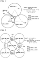
- Fig. 1 shows a schematic view in which one fine WC grain 2 having a grain size r2 invades into a region surrounded by three coarse WC grains 1 having a grain size r1, and a close-packed structure formed of three coarse WC grains 1 and one fine WC grain 2 is formed.
- the value of r2/r1 is required to be approximately 0.15.
- the grain sizes of the coarse WC grains 1 are all r1
- the grain sizes of the fine WC grains 2 are all r2.
- Fig. 2 shows a schematic view in which one fine WC grain 2 having a grain size r2 invades into a region surrounded by four coarse WC grains 1 having a grain size r1, and a structure close to a close-packed structure formed of four coarse WC grains 1 and one fine WC grain 2 is formed.
- the value of r2/r1 is required to be approximately 0.42.
- the grain sizes of the coarse WC grains 1 are all r1
- the grain sizes of the fine WC grains 2 are all r2.
- r2/r1 The value of r2/r1 obtained above is calculated on the assumption of the coarse WC grains 1 having the same size and the fine WC grains 2 having the same size.
- WC grains in actual WC-based cemented carbide have different sizes, the above idea cannot be directly applied as a method for forming a close-packed structure of the WC grains.
- a mixed powder consisting of a coarse grain WC powder PI having a grain size d1 and a fine grain WC powder P2 having a grain size d2 is prepared, mixed with another raw material powder containing a Co powder, pulverized, mixed and stirred while suppressing the degree of pulverization as much as possible, and then sintered to produce a WC-based cemented carbide sintered body, a sintered body texture is formed in which WC grains having a grain size r1 and WC grains having a grain size r2 coexist in the WC-based cemented carbide sintered body.
- r1 or r2 of the WC-based cemented carbide exhibits little change in grain size since the degree of pulverization is suppressed to a low level in the step of pulverizing, mixing, and stirring the raw material powder. Accordingly, r1 or r2 of the WC grains of the sintered body can be said to be approximately the same as d1 or d2.
- the ratio r2/r1 of r2 to r1 of the WC grains in the WC-based cemented carbide is in a range of approximately 0.15 to 0.60, and a close-packed structure or a texture close thereto is prepared.
- an actual WC powder does not have a single grain size such as d1 or d2 but has a grain size distribution, it is required to consider a grain size distribution of the WC powder as a raw material powder or a grain size distribution of the WC grains in the WC-based cemented carbide in order to form the close-packed structure of the WC grains in the WC-based cemented carbide.
- the inventors focused on a most frequent value, which is a factor that characterizes the grain size distribution, and performed an experiment by associating a grain size r1 corresponding to the most frequent value formed on the coarse grain side of 3 ⁇ m or more with a grain size r2 corresponding to the most frequent value formed on the fine grain side of less than 3 ⁇ m in the grain size distribution having a plurality of local maximums.
- WC-based cemented carbide in which WC grains have a structure close to a close-packed structure can be produced in a case where a sintered body is produced by blending a coarse grain WC powder and a fine grain WC powder so that a grain size ratio r2/r1 is 0.15 or more and 0.60 or less and a total area ratio of WC grains having a grain size of 0.50 to 1.20 times r2 in the total of a total area A1 of WC grains having a grain size of 0.75 to 1.20 times r1 and a total area A2 of WC grains having a grain size of 0.50 to 1.20 times r2, that is, A2 ⁇ 100/(A1+A2) is 5 to 35 area%.
- the fine WC grains cannot exhibit an effect of sufficiently increasing the contact length between the WC-WC grains, and in a case where the above blending ratio is greater than 35 vol%, the coarse WC grains in the WC-based cemented carbide cannot form a close-packed structure which forms a base skeleton.
- the present invention in order to form a close-packed structure or a structure close thereto of the WC grains in the WC-based cemented carbide, it is important to adjust the grain size distribution of each of the coarse grain WC powder and the fine grain WC powder as a WC raw material powder to be used, and to adjust the blending amounts of the coarse grain WC powder and the fine grain WC powder, and a WC-based cemented carbide tool formed of WC-based cemented carbide obtained by appropriately adjusting the grain size distributions and the blending amounts exhibits excellent plastic deformation resistance and chipping resistance in the cutting of a hard-to-cut material such as stainless steel.
- a characteristic of the manufacturing steps in the present invention is to use a method of selecting, mixing, and sintering such a raw material WC that a grain size ratio d2/d1 and a grain amount ratio of grains having a grain size d1 and grains having a grain size d2 can be made to be equal to a grain size ratio r2/r1 and a grain amount ratio of grains having a grain size r1 and grains having a grain size r2, respectively, and thus a target alloy texture is achieved.
- polycrystalline WC was not employed since there was a possibility of a deviation from the original grain size due to the grain crushing and pulverization in the mixing process. Only monocrystalline WC was used.
- the WC grain size distribution can be approximated by a Gaussian function where a horizontal axis represents the WC grain size and a vertical axis represents the WC frequency in the measurement by a laser diffraction and scattering type grain size distribution measuring method, and a raw material WC was selected in which a value of 3 ⁇ of the coarse WC grains was equal to or less than a value of 0.20 ⁇ d1 and a value of 3 ⁇ of the fine WC grains was equal to or less than a value of 0.20 ⁇ d2, where ⁇ is a standard deviation calculated from the Gaussian function approximated.
- the mixing method in order to prevent that the WC grains are pulverized and their sizes are thus changed from the original grain size of the raw material WC, mixing with low pulverization energy, preferably medialess mixing was introduced. Furthermore, in the sintering method, in a case where the sintering is performed at a high temperature for a long period of time, the WC grains grow and the growth causes a deviation from the original grain size. Accordingly, the sintering was performed under such optimum sintering conditions of a low temperature and a short period of time that defects (pores) were not generated in the alloy.
- the WC-based cemented carbide tool of the present invention can be produced by, for example, the following steps.
- two types of monocrystalline WC powders having different grain size distributions are blended so as to have a predetermined blending ratio, a raw material powder formed of a Co powder and a Cr 3 C 2 powder or a raw material powder further containing one or more of a TaC powder, an NbC powder, a TiC powder, and a ZrC powder as necessary is further added, and the powders are blended and mixed without the application of a large crushing force by, for example, medialess mixing by an attritor with a reduced amount of media, preferably an ultrasonic homogenizer, a cyclone mixer, or the like to produce a mixed powder.
- a powder compact is produced by molding the mixed powder.
- the powder compact is sintered under conditions of a low temperature and a short period of time under a vacuum atmosphere: heating temperature: 1,300°C or higher and 1,500°C or lower, preferably 1,300°C or higher and 1,400°C or lower; and heating holding time: 15 to 120 minutes, preferably 15 to 60 minutes to produce WC-based cemented carbide so that changes in the WC shape and the grain size distribution due to the growth of the grains are suppressed.
- the WC-based cemented carbide can be machined and ground to produce a WC-based cemented carbide tool having a desired size and a desired shape.
- the contact length between the WC-WC grains is increased, the occurrence of grain boundary sliding at the interface of the WC-WC grains is reduced, and thus the plastic deformation resistance is improved.
- the coarse WC grains and the fine WC grains are mixed in the alloy texture, even in a case where fractures occur in the WC-based cemented carbide, the advance of linear fractures is suppressed and the toughness is improved.
- a surface-coated WC-based cemented carbide cutting tool can be produced.
- the type of the hard film and the film forming method employed may be a film type and a film forming method which have already been known to those skilled in the art, and are not particularly limited.
- WC-based cemented carbide tools 1 to 9 of comparative examples (hereinafter, referred to as the comparative example tools 1 to 9) were manufactured for comparison.
- powders for sintering having a blending composition shown in Table 2, that is, a WC grain size ratio and a blending ratio of coarse grains and fine grains in which d2/d1 was 0.15 or more and 0.60 or less or (blending amount of fine WC grains having the most frequent value of d2)/(blending amount of coarse WC grains having the most frequent value of d1+blending amount of fine WC grains having the most frequent value of d2) was out of a range of 5% to 35% were wet-mixed by medialess attritor mixing at a rotation speed of 50 rpm for 8 hours, dried, and then press-formed at a pressure of 100 MPa to produce powder compacts.
- Table 2 that is, a WC grain size ratio and a blending ratio of coarse grains and fine grains in which d2/d1 was 0.15 or more and 0.60 or less or (blending amount of fine WC grains having the most frequent value of d2)/(blending amount of coarse WC grains having the most frequent value of d1+blending amount of
- the comparative example tools 1 to 9 shown in Table 4 were produced by performing the same steps as (c) and (d) in the manufacturing steps of the present invention tools 1 to 11.
- Tables 3 and 4 show the average contents of the components.
- each WC grain was measured by analyzing a crystal orientation mapping image of the WC grains, a diameter when the WC grain was approximated to a circle of the same area was calculated, and a grain size distribution graph was made with a vertical axis representing a grain area ratio (a ratio of a total area of WC grains having the corresponding grain size to a total area of all WC grains in the measurement range) and a horizontal axis representing the grain size.
- the horizontal axis is divided by 0.2 ⁇ m width, and the minimum value is 0.1 ⁇ m.
- the WC grain size is a value in the middle of the dividing width.
- the cross-section used for observation by EBSD and SEM is an optional cross-section, and in this example, a cross-section of the alloy processed by ion milling by 100 ⁇ m or more from the outermost surface of the flank face was observed.
- the observation range in EBSD was a field of view of 24 ⁇ 72 ⁇ m, and the number of WC grains was set to 4,000 or more in the measurement range.
- the observation conditions in EBSD included a pixel size of 0.1 ⁇ m ⁇ 0.1 ⁇ m and a capturing time of 15 ms/point.
- the observation range in SEM was a field of view of 24 ⁇ 72 ⁇ m, and the number of WC grains was set to 4,000 or more in the measurement range.
- the observation conditions in SEM included an acceleration voltage of 15 kV.
- a grain size corresponding to the most frequent value formed on the coarse grain side of 3 ⁇ m or more was represented by r1
- a grain size corresponding to the most frequent value formed on the fine grain side of less than 3 ⁇ m was represented by r2.
- a total area A1 ( ⁇ m 2 ) of WC grains having a grain size of 0.75 to 1.20 times r1 and a total area A2 ( ⁇ m 2 ) of WC grains having a grain size of 0.50 to 1.20 times r2 were obtained, and a total area ratio (A2 ⁇ 100/(A1+A2) area%) of the WC grains having a grain size of 0.50 to 1.20 times r2 to a total of the total area A1 of the WC grains having a grain size of 0.75 to 1.20 times r1 and the total area A2 of the WC grains having a grain size of 0.50 to 1.20 times r2 was obtained.
- Tables 3 and 4 show the measurement results. Since crushed monocrystalline WC grains which are difficult to pulverize and crush are used, and a medialess mixing method avoiding the pulverization of the grains and sintering conditions of a low temperature and a short period of time for suppressing the growth of the grains are introduced in the manufacturing steps, it has been found that "r2/r1" approximately reflects “d2/d1" of the raw material and "A2 ⁇ 100/(A1+A2)" approximately reflects the blending ratio of the coarse WC grains and the fine WC grains "(blending amount of fine WC grains having the most frequent value of d2)/(blending amount of coarse WC grains having the most frequent value of d1+blending amount of fine WC grains having the most frequent value of d2)".
- flank face plastic deformation amount of the cutting edge was measured, and the wear state of the cutting edge was observed.
- a line segment was drawn with respect to a main cutting edge-side flank face of the tool on a ridge where the main cutting edge-side flank face and the rake face intersected at a position sufficiently away from the cutting edge, the line segment was extended in a cutting edge portion direction, and a part where a distance between the extended line segment and the ridge of the cutting edge portion (in a direction vertical to the extended line segment) was the longest was measured and defined as the flank face plastic deformation amount of the cutting edge.
- a wear state when the flank face plastic deformation amount was 0.04 mm or more was defined as edge tip deformed.
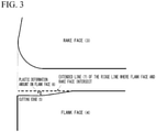
- Fig. 3 shows a schematic view of the measurement of the flank face plastic deformation amount.
- Table 5 shows the measurement results.
- a hard coating layer having an average layer thickness shown in Table 6 was formed by coating on the cutting edge surfaces of the present invention tools 1 to 4 and the comparative example tools 1 to 4 by a PVD method or a CVD method to produce the present invention surface-coated WC-based cemented carbide cutting tools (hereinafter, referred to as "the present invention coated tools") 1 to 4 and comparative example surface-coated WC-based cemented carbide cutting tools (hereinafter, referred to as "comparative example coated tools”) 1 to 4.
- the comparative example tools and the comparative example coated tools had poor chipping resistance and plastic deformation resistance, and had a short life.
- a WC-based cemented carbide tool and a coated tool of the present invention have excellent plastic deformation resistance and chipping resistance in a case where the tools are provided for cutting of a hard-to-cut material such as stainless steel. Even in a case where the tools are applied to other work materials and cutting conditions, the tools exhibit excellent cutting performance over a long period of use, and the life of the tools are expected to be increased.
Landscapes
- Chemical & Material Sciences (AREA)
- Engineering & Computer Science (AREA)
- Materials Engineering (AREA)
- Mechanical Engineering (AREA)
- Metallurgy (AREA)
- Organic Chemistry (AREA)
- Powder Metallurgy (AREA)
- Cutting Tools, Boring Holders, And Turrets (AREA)
Abstract
Description
- The present invention relates to a WC-based cemented carbide cutting tool (also referred to as "WC-based cemented carbide tool") having excellent plastic deformation resistance and exhibiting excellent chipping resistance in the cutting of a hard-to-cut material such as stainless steel, and a surface-coated WC-based cemented carbide cutting tool.
- Priority is claimed on
Japanese Patent Application No. 2019-057278, filed March 25, 2019 - Since WC-based cemented carbide has high hardness and toughness, a WC-based cemented carbide tool having a cutting tool body made of WC-based cemented carbide is known as a cutting tool which exhibits excellent wear resistance and has a long life over long term use.
- However, in recent years, various proposals have been made to further improve the cutting performance and tool life of the WC-based cemented carbide tool according to the type of a work material, cutting conditions, and the like.
- For example,
Patent Document 1 proposes cemented carbide which has a hard phase mainly containing tungsten carbide and a binder phase mainly containing an iron group element (including cobalt, the cobalt content is preferably 8 mass% or more in the cemented carbide), and satisfies B/A≤0.05, where A is the number of grains of the tungsten carbide and B is the number of tungsten carbide grains having one or less point of contact with other tungsten carbide grains, so that the plastic deformation resistance of the cemented carbide is improved, and as a result, the life of a WC-based cemented carbide tool is increased in the wet continuous cutting of carbon steel and stainless steel. -
Patent Document 2 proposes a WC-based cemented carbide tool which has: a Co amount of 10 to 13 mass%; a ratio of a Cr amount to the Co amount of 2% to 8%; at least one of TaC and NbC contained so that a total amount of TaC and NbC is in a range of 0.2 to 0.5 mass%; a balance consisting of WC; and hardness of 88.6 HRA to 89.5 HRA, in which a ratio D80/D20 of a diameter D80 corresponding to 80% in terms of WC integrated grain size to a diameter D20 corresponding to 20% in terms of integrated grain size in area ratio on a polished surface is in a range of 2.0≤D80/D20≤4.0, D80 is in a range of 4.0 to 7.0 µm, and a WC adhesion degree c is 0.36≤c≤0.43 so that the adhesion of a work material is prevented and the fracture resistance is improved in the cutting of a hard-to-cut material typified by stainless steel. -
Patent Document 3 proposes a WC-based cemented carbide drill in which in a case where a component composition of WC-based cemented carbide is represented by WC-x mass% Co-y mass% Cr3C2-z mass% VC, 6≤x≤14, 0.4≤y≤0.8, 0≤z≤0.6, and (y+z)≤0.1x are satisfied, the WC-based cemented carbide has a WC adhesion degree C so that in a case where the WC adhesion degree C of the WC-based cemented carbide is represented by C=1-Vb α·exp(0.391·L), a value Vb of a binder phase volume fraction of the WC-based cemented carbide in the above formula is 0.11≤Vb≤0.25, a value L of (standard deviation of grain size distribution of WC grains)/(average WC grain size) is in a range of 0.3<L<0.7, and a coefficient α satisfies 0.3≤α≤0.55, and thus toughness is improved with no reduction in hardness and rigidity and fracture resistance is thereby increased in the cutting of an A1 alloy, carbon steel, and the like. -
Patent Document 4 proposes a WC-based cemented carbide tool in which in a case where a WC-WC adhesion interface length is represented by L1 and a WC-Co adhesion interface length is represented by L2, - a formula of R>(0.82-0.086×D)×(10/V)
- is satisfied to improve the thermal plastic deformation resistance and toughness of the WC-based cemented carbide tool in the cutting of an Ni-based heat resistant alloy.

- D: WC area average grain size (µm), which is in a range of 0.6≤D≤1.5
- Here, D is a grain size of WC when the area ratio of WC is 50%.
- V: binder phase volume (vol%), which is in a range of 9≤V≤14.
-
Patent Document 5 proposes a method of manufacturing a WC-based cemented carbide tool having a bimodal grain size distribution, including: wet-mixing WC powders having various grain size distributions together with a binder metal and a pressure forming agent without kneading; drying; pressure-forming; and sintering, in which grains of the WC powder are classified into two groups of a small grain group having a maximum grain size amax and a large grain group having a minimum grain size bmin, each group containing at least 10% of the total amount of the WC grains, bmin-amax>0.5 µm is satisfied, and the grain size variation in each group is >1 µm. - It is also proposed that the grains of the small grain group are previously coated with a grain growth inhibitor, the grains of the large grain group are previously coated with a binder metal, the WC-based cemented carbide tool includes WC, 4 to 20 wt% of Co, and <30 wt% of a cubic carbide as a mixture or solid solution containing TiC, TaC, NbC, or WC, the WC grains are classified into two groups, and a weight ratio of coarse WC grains of 2.5 to 6.0 µm to fine WC grains of 1.5 µm or less is in a range of 0.25 to 4.0.
- In addition, the WC-based cemented carbide tool produced by the above manufacturing method exhibits excellent wear resistance in the truning of stainless steel.
-
Patent Document 6 proposes a WC-based cemented carbide tool for an end mill in which WC-based cemented carbide containing chromium carbide has two types of tungsten carbide phases having different average grain sizes dispersed in a binder phase, a ratio of the average grain sizes of the two types of tungsten carbide phases satisfies 3≤average grain size (large)/average grain size (small)≤7, a volume ratio therebetween satisfies 1.5≤volume of average grain size (large)/volume of average grain size (small)≤3, the binder phase contains 0.5 to 2.0 wt% of chromium carbide and 5 to 15 wt% of Co, and a maximum grain size of the tungsten carbide phase is 3.0 µm or less. - In addition, for example, the WC-based cemented carbide tool for an end mill exhibits excellent strength, toughness, and crack propagation resistance in the end mill machining of alloy steel by dispersing two types of tungsten carbide grains having different grain sizes in the binder phase and performing solid-solution strengthening of the chromium carbide in the binder phase.
-
- [Patent Document 1]
Japanese Patent No. 6256415 - [Patent Document 2]
Japanese Unexamined Patent Application, First Publication No. 2017-88999 - [Patent Document 3]
Japanese Unexamined Patent Application, First Publication No. 2017-148895 - [Patent Document 4]
Japanese Unexamined Patent Application, First Publication No. 2017-179433 - [Patent Document 5]
Japanese Patent No. 4970638 - [Patent Document 6]
Japanese Patent No. 3605740 - According to the conventional WC-based cemented carbide tools proposed in
Patent Documents 1 to 6, the cutting performance and tool characteristics of the WC-based cemented carbide tool are improved by controlling the point of contact between the WC-WC grains, the grain size of the WC grains, the grain size distribution of the WC grains, the WC adhesion degree, and the like. - However, in the conventional tools, the plastic deformation resistance is not sufficient in the cutting of a hard-to-cut material such as stainless steel, and it is difficult to suppress the advance of fractures due to insufficient toughness. Accordingly, the tool life was short due to the occurrence of abnormal damage such as deformation or chipping of an edge tip.
- In order to provide a WC-based cemented carbide tool exhibiting excellent plastic deformation resistance and chipping resistance in the cutting of a hard-to-cut material such as stainless steel, the present inventors have pursued intensive studies focusing on the form of WC grains of WC-based cemented carbide, and found the following findings.
- That is, the inventors have found that in a case where WC grains form a texture state approximately close to a close-packed structure in a WC-based cemented carbide tool, the WC grains form a strong skeleton structure, and as a result, a contact length between the WC-WC grains is increased, the occurrence of grain boundary sliding at the interface of the WC-WC grains is reduced, and thus the plastic deformation resistance is improved.
- It has also been found that since coarse WC grains and fine WC grains are mixed in the alloy texture, even in a case where fractures occur in the WC-based cemented carbide, the advance of linear fractures is suppressed, and as a result, the WC-based cemented carbide has improved toughness.
- Accordingly, in a case where a WC-based cemented carbide tool in which WC grains in WC-based cemented carbide have a texture close to a close-packed structure is provided for cutting of a hard-to-cut material such as stainless steel, deformation of an edge tip of the tool is suppressed due to an improvement in the plastic deformation resistance, and the occurrence of abnormal damage such as chipping is also suppressed due to the suppression of the advance of fractures, so that the life of the tool can be increased.
- The present invention is contrived based on the above findings, and has the following aspects.
- (1) A WC-based cemented carbide cutting tool including: a cutting tool body made of WC-based cemented carbide, in which the WC-based cemented carbide has a component composition containing Co: 5 to 14 mass%, Cr3C2: 0.1 to 1.4 mass%, and a the WC balance containing inevitable impurities,
in a case where a grain size distribution is obtained based on area by measuring grain sizes of WC grains in a cross-section of the WC-based cemented carbide, a plurality of local maximums are present in the grain size distribution, and in a case where a grain size corresponding to a most frequent value formed on a coarse grain side is represented by r1, and a grain size corresponding to a most frequent value formed on a fine grain side is represented by r2, a grain size ratio r2/r1 is 0.15 or more and 0.60 or less, and an area ratio A2×100/(A1+A2) is 5 to 35 area%, A1 being a total area of WC grains having a grain size of 0.75 to 1.20 times of r1 and A2 being a total area of WC grains having a grain size of 0.50 to 1.20 times of r2. - (2) The WC-based cemented carbide cutting tool according to (1), in which the WC-based cemented carbide further contains at least one selected from TaC, NbC, TiC, and ZrC in a total amount of 4 mass% or less.
- (3) A surface-coated WC-based cemented carbide cutting tool including the WC-based cemented carbide cutting tool according to (1) or (2) and a hard coating layer formed on at least a cutting edge of the WC-based cemented carbide cutting tool. The contents of Cr3C2, TaC, NbC, TiC, and ZrC in (1) and (2) are values obtained by expressing a Cr amount, a Ta amount, an Nb amount, a Ti amount, and a Zr amount measured in a cross-section of the WC-based cemented carbide in terms of carbide, respectively.
- In a WC-based cemented carbide tool and a surface-coated WC-based cemented carbide cutting tool according to an aspect of the present invention (hereinafter, referred to as "WC-based cemented carbide tool of the present invention" and "surface-coated WC-based cemented carbide cutting tool of the present invention"), Co and Cr3C2, which are components of WC-based cemented carbide constituting a body of the tool, and optional TaC, NbC, TiC, and ZrC have a specific composition range. In addition, since WC grains in the WC-based cemented carbide have a texture state approximately close to a close-packed structure, a contact length between the WC-WC grains is increased, the occurrence of grain boundary sliding at a WC-WC interface is suppressed, the cutting tool has excellent plastic deformation resistance, and deformation of an edge tip is suppressed. In addition, since coarse WC grains and fine WC grains are mixed in the alloy texture, even in a case where fractures occur in the WC-based cemented carbide, the advance of linear fractures is suppressed, and resistance to abnormal damage such as chipping is improved.
-
-
Fig. 1 shows a schematic view of a case where a close-packed structure formed of three coarse WC grains and one fine WC grain is formed in WC-based cemented carbide. r2/r1 obtained by solving a formula of cos 30°=(r1/2)/(r1/2+r2/2)=31/2/2 satisfies r2/r1 ⊐0.15 (where r1 is a diameter of the coarse WC grain. r2 is a diameter of the fine WC grain). -
Fig. 2 shows a schematic view of a case where a close-packed structure formed of four coarse WC grains and one fine WC grain is formed in WC-based cemented carbide. r2/rl obtained by solving a formula of cos 45°=(r1+r2)/(2×r1)=1/√2 satisfies r2/r10.414 (where r1 is a diameter of the coarse WC grain. r2 is a diameter of the fine WC grain).
-
Fig. 3 shows a schematic view of the measurement of a flank face plastic deformation amount of a cutting edge. The upper view (rake face) is a plan view, and the lower view (flank face) is a side view. As the flank face plastic deformation amount of the cutting edge, the amount of deformation of a ridge of the cutting edge pushed by cutting is measured after cutting with reference to the ridge of the cutting edge not undergoing deformation before cutting. As a specific measuring method, a line segment is drawn with respect to a main cutting edge-side flank face of the tool on a ridge where the main cutting edge-side flank face and the rake face intersect at a position sufficiently away from the cutting edge, the line segment is extended in a cutting edge portion direction, and a part where a distance between the extended line segment and the ridge of the cutting edge portion (in a direction vertical to the extended line segment) is the longest is measured and defined as the flank face plastic deformation amount of the cutting edge. - Hereinafter, the present invention will be described in detail.
- Co is contained as a main binder phase forming component of WC-based cemented carbide. In a case where the Co content is less than 5 mass%, sufficient toughness cannot be maintained. In contrast, in a case where the Co content is greater than 14 mass%, the alloy rapidly softens, desired hardness required for a cutting tool cannot be obtained, and deformation and wear remarkably progress. Therefore, the Co content in the WC-based cemented carbide was set to 5 to 14 mass%.
- In Cr3C2, Cr forms solid solutions in Co which forms the main binder phase, and causes solid solution strengthening of Co, thereby increasing the strength of the WC-based cemented carbide. However, in a case where the Cr3C2 content is less than 0.1 mass%, the above action does not sufficiently occur. In contrast, in a case where the Cr3C2 content is greater than 10% of the Co content, a composite carbide of Cr and W precipitates, the toughness is reduced, and it becomes a starting point of the occurrence of fractures.
- Since the upper limit of the Co content is 14 mass% in the present invention, the upper limit of the Cr3C2 content is 1.4 mass%, that is 10% of the upper limit of the Co content.
- Therefore, the Cr3C2 content in the WC-based cemented carbide was set to 0.1 to 1.4 mass%.
- The WC-based cemented carbide of the present invention may further contain at least one selected from TaC, NbC, TiC, and ZrC as a component of the WC-based cemented carbide in a total amount of 4 mass% or less.
- TaC, NbC, TiC, and ZrC all have an effect of increasing oxidation resistance and crater wear resistance. However, in a case where the total content in terms of carbide is greater than 4 mass%, the wear resistance is insufficient. In addition, agglomerates are likely to be formed, which become a starting point of the occurrence of fractures.
- Therefore, in a case where at least one selected from TaC, NbC, TiC, and ZrC is contained as a component in the WC-based cemented carbide, the total content thereof is preferably 4 mass% or less.
- The contents of Cr3C2, TaC, NbC, TiC, and ZrC described above are values obtained by expressing a Cr amount, a Ta amount, an Nb amount, a Ti amount, and a Zr amount measured by EPMA for the WC-based cemented carbide in terms of carbide, respectively.
- WC grains in the WC-based cemented carbide in a WC-based cemented carbide tool of the present invention have a close-packed structure or a texture close to the close-packed structure, and this will be described with the schematic views of
Figs. 1 and 2 . - First,
Fig. 1 will be described. -
Fig. 1 shows a schematic view in which onefine WC grain 2 having a grain size r2 invades into a region surrounded by threecoarse WC grains 1 having a grain size r1, and a close-packed structure formed of threecoarse WC grains 1 and onefine WC grain 2 is formed. 0.156 is obtained in a case where the above formula is solved.
- Therefore, in order to form the close-packed structure as shown in the schematic view of
Fig. 1 , the value of r2/r1 is required to be approximately 0.15. - Here, it is assumed that the grain sizes of the
coarse WC grains 1 are all r1, and the grain sizes of thefine WC grains 2 are all r2. - Next,
Fig. 2 will be described. -
Fig. 2 shows a schematic view in which onefine WC grain 2 having a grain size r2 invades into a region surrounded by fourcoarse WC grains 1 having a grain size r1, and a structure close to a close-packed structure formed of fourcoarse WC grains 1 and onefine WC grain 2 is formed. - Here, assuming a virtual lattice as shown by the dotted line in
Fig. 2 , which has a lattice length a, 2×r1=√2×a and 0.414 is obtained in a case where the above formula is solved.
- Therefore, in order to form the approximately close-packed structure as shown in the schematic view of
Fig. 2 , the value of r2/r1 is required to be approximately 0.42. The value obtained here is a calculated value. Accordingly, the inventors performed an experiment for confirmation with reference to the value, and found that an effect of improving the plastic deformation resistance is obtained up to r2/r1=0.60. Thus, the upper limit of the grain size ratio was set to r2/r1=0.60. - Here, it is also assumed that the grain sizes of the
coarse WC grains 1 are all r1, and the grain sizes of thefine WC grains 2 are all r2. - The value of r2/r1 obtained above is calculated on the assumption of the
coarse WC grains 1 having the same size and thefine WC grains 2 having the same size. However, since WC grains in actual WC-based cemented carbide have different sizes, the above idea cannot be directly applied as a method for forming a close-packed structure of the WC grains. - However, by applying the above idea to WC grains as a raw material powder for producing WC-based cemented carbide, it can be useful for forming a close-packed structure of the WC grains in WC-based cemented carbide after sintering.
- For example, in a case where a mixed powder consisting of a coarse grain WC powder PI having a grain size d1 and a fine grain WC powder P2 having a grain size d2 is prepared, mixed with another raw material powder containing a Co powder, pulverized, mixed and stirred while suppressing the degree of pulverization as much as possible, and then sintered to produce a WC-based cemented carbide sintered body, a sintered body texture is formed in which WC grains having a grain size r1 and WC grains having a grain size r2 coexist in the WC-based cemented carbide sintered body.
- Here, r1 or r2 of the WC-based cemented carbide exhibits little change in grain size since the degree of pulverization is suppressed to a low level in the step of pulverizing, mixing, and stirring the raw material powder. Accordingly, r1 or r2 of the WC grains of the sintered body can be said to be approximately the same as d1 or d2.
- In this case, in a case where the value of d2/dl in the WC raw material powder is in a range of 0.15 to 0.60, the ratio r2/r1 of r2 to r1 of the WC grains in the WC-based cemented carbide is in a range of approximately 0.15 to 0.60, and a close-packed structure or a texture close thereto is prepared.
- However, since an actual WC powder does not have a single grain size such as d1 or d2 but has a grain size distribution, it is required to consider a grain size distribution of the WC powder as a raw material powder or a grain size distribution of the WC grains in the WC-based cemented carbide in order to form the close-packed structure of the WC grains in the WC-based cemented carbide.
- Accordingly, the inventors focused on a most frequent value, which is a factor that characterizes the grain size distribution, and performed an experiment by associating a grain size r1 corresponding to the most frequent value formed on the coarse grain side of 3 µm or more with a grain size r2 corresponding to the most frequent value formed on the fine grain side of less than 3 µm in the grain size distribution having a plurality of local maximums. As is clear from examples to be described later, it was experimentally confirmed that WC-based cemented carbide in which WC grains have a structure close to a close-packed structure can be produced in a case where a sintered body is produced by blending a coarse grain WC powder and a fine grain WC powder so that a grain size ratio r2/r1 is 0.15 or more and 0.60 or less and a total area ratio of WC grains having a grain size of 0.50 to 1.20 times r2 in the total of a total area A1 of WC grains having a grain size of 0.75 to 1.20 times r1 and a total area A2 of WC grains having a grain size of 0.50 to 1.20 times r2, that is, A2×100/(A1+A2) is 5 to 35 area%.
- That is, according to the examples to be described later, in a case of r2/r1> 0.60, the grain size difference between the coarse WC grains and the fine WC grains is too small, which disturbs an ideal packed structure. In addition, in a case of r2/r1<0.15, even in a case where the fine WC grains enter the gap between the coarse WC grains, the grains cannot come into contact with each other, and an ideal packed structure cannot be provided. Thus, it is not possible to provide an effect of improving the plastic deformation resistance.
- Furthermore, in a case where the blending ratio of the fine grain WC powder in the total of the coarse grain WC powder and the fine grain WC powder is less than 5 vol%, the fine WC grains cannot exhibit an effect of sufficiently increasing the contact length between the WC-WC grains, and in a case where the above blending ratio is greater than 35 vol%, the coarse WC grains in the WC-based cemented carbide cannot form a close-packed structure which forms a base skeleton.
- As described above, in the present invention, in order to form a close-packed structure or a structure close thereto of the WC grains in the WC-based cemented carbide, it is important to adjust the grain size distribution of each of the coarse grain WC powder and the fine grain WC powder as a WC raw material powder to be used, and to adjust the blending amounts of the coarse grain WC powder and the fine grain WC powder, and a WC-based cemented carbide tool formed of WC-based cemented carbide obtained by appropriately adjusting the grain size distributions and the blending amounts exhibits excellent plastic deformation resistance and chipping resistance in the cutting of a hard-to-cut material such as stainless steel.
- A characteristic of the manufacturing steps in the present invention is to use a method of selecting, mixing, and sintering such a raw material WC that a grain size ratio d2/d1 and a grain amount ratio of grains having a grain size d1 and grains having a grain size d2 can be made to be equal to a grain size ratio r2/r1 and a grain amount ratio of grains having a grain size r1 and grains having a grain size r2, respectively, and thus a target alloy texture is achieved. Specifically, for the raw material WC, polycrystalline WC was not employed since there was a possibility of a deviation from the original grain size due to the grain crushing and pulverization in the mixing process. Only monocrystalline WC was used. As the monocrystalline raw material WC used, a crushed product without agglomeration was used in order to prevent the grains from being crushed during the mixing process and the size thereof from deviating from the original grain size for the same reason as described above. The WC grain size distribution can be approximated by a Gaussian function where a horizontal axis represents the WC grain size and a vertical axis represents the WC frequency in the measurement by a laser diffraction and scattering type grain size distribution measuring method, and a raw material WC was selected in which a value of 3σ of the coarse WC grains was equal to or less than a value of 0.20×d1 and a value of 3σ of the fine WC grains was equal to or less than a value of 0.20×d2, where σ is a standard deviation calculated from the Gaussian function approximated. In addition, in the mixing method, in order to prevent that the WC grains are pulverized and their sizes are thus changed from the original grain size of the raw material WC, mixing with low pulverization energy, preferably medialess mixing was introduced. Furthermore, in the sintering method, in a case where the sintering is performed at a high temperature for a long period of time, the WC grains grow and the growth causes a deviation from the original grain size. Accordingly, the sintering was performed under such optimum sintering conditions of a low temperature and a short period of time that defects (pores) were not generated in the alloy.
- Based on the above thought, the WC-based cemented carbide tool of the present invention can be produced by, for example, the following steps.
- First, two types of monocrystalline WC powders having different grain size distributions are blended so as to have a predetermined blending ratio, a raw material powder formed of a Co powder and a Cr3C2 powder or a raw material powder further containing one or more of a TaC powder, an NbC powder, a TiC powder, and a ZrC powder as necessary is further added, and the powders are blended and mixed without the application of a large crushing force by, for example, medialess mixing by an attritor with a reduced amount of media, preferably an ultrasonic homogenizer, a cyclone mixer, or the like to produce a mixed powder.
- Then, a powder compact is produced by molding the mixed powder. The powder compact is sintered under conditions of a low temperature and a short period of time under a vacuum atmosphere: heating temperature: 1,300°C or higher and 1,500°C or lower, preferably 1,300°C or higher and 1,400°C or lower; and heating holding time: 15 to 120 minutes, preferably 15 to 60 minutes to produce WC-based cemented carbide so that changes in the WC shape and the grain size distribution due to the growth of the grains are suppressed.
- Then, the WC-based cemented carbide can be machined and ground to produce a WC-based cemented carbide tool having a desired size and a desired shape.
- In the WC-based cemented carbide tool produced in the above steps, the contact length between the WC-WC grains is increased, the occurrence of grain boundary sliding at the interface of the WC-WC grains is reduced, and thus the plastic deformation resistance is improved. In addition, since the coarse WC grains and the fine WC grains are mixed in the alloy texture, even in a case where fractures occur in the WC-based cemented carbide, the advance of linear fractures is suppressed and the toughness is improved.
- Furthermore, by forming a hard film such as a Ti-Al or Al-Cr-based carbide, nitride, or carbonitride, or Al2O3 on at least the cutting edge of the WC-based cemented carbide cutting tool by coating using a film forming method such as PVD or CVD, a surface-coated WC-based cemented carbide cutting tool can be produced.
- In the production of the surface-coated WC-based cemented carbide cutting tool, the type of the hard film and the film forming method employed may be a film type and a film forming method which have already been known to those skilled in the art, and are not particularly limited.
- The WC-based cemented carbide tool and the surface-coated WC-based cemented carbide cutting tool of the present invention will be described in greater detail with reference to examples.
-
- (a) First, as powders for sintering, two types of monocrystalline WC powders (a coarse grain WC powder having a most frequent value of d1 (µm) in its grain size distribution and a fine grain WC powder having a most frequent value of d2 (µm) in its grain size distribution) having different grain size distributions, a Co powder, a Cr3C2 powder, a TaC powder, an NbC powder, a TiC powder, and a ZrC powder are prepared.
- These powders were blended so as to have a blending composition shown in Table 1, that is, blended so as to have a WC grain size ratio and a blending ratio of coarse grains and fine grains in which d2/d1 was 0.15 or more and 0.60 or less and (blending amount of fine WC grains having the most frequent value of d2)/(blending amount of coarse WC grains having the most frequent value of d1+blending amount of fine WC grains having the most frequent value of d2) satisfied 5% to 35%. Thus, powders for sintering were produced.
- Table 1 shows the blending compositions (mass%) of various powders, the values of the grain sizes d1 and d2 corresponding to the most frequent values of the two types of WC powders in the grain size distributions, and the blending ratios of the fine WC grains and the coarse WC grains.
- The average grain sizes (D50) of the Co powder, the Cr3C2 powder, the TaC powder, the NbC powder, the TiC powder, and the ZrC powder are in a range of 1.0 to 3.0 µm.
- (b) The powders for sintering prepared by blending so as to have a blending composition shown in Table 1 were wet-mixed by medialess attritor mixing at a rotation speed of 50 rpm for 8 hours, dried, and then pressure-formed at a pressure of 100 MPa to produce powder compacts.
- (c) Then, these powder compacts were sintered under conditions of heating temperature: 1,300°C or higher and 1,500°C or lower and heating holding time: 15 to 120 minutes under a vacuum atmosphere, and WC-based cemented carbides were produced.
- (d) Then, the WC-based cemented carbides were machined and ground to produce WC-based cemented
carbide tools 1 to 11 (hereinafter, referred to as thepresent invention tools 1 to 11) of an insert shape of CNMG120408-GM shown in Table 3. - WC-based cemented
carbide tools 1 to 9 of comparative examples (hereinafter, referred to as thecomparative example tools 1 to 9) were manufactured for comparison. - In steps of manufacturing the tools, powders for sintering having a blending composition shown in Table 2, that is, a WC grain size ratio and a blending ratio of coarse grains and fine grains in which d2/d1 was 0.15 or more and 0.60 or less or (blending amount of fine WC grains having the most frequent value of d2)/(blending amount of coarse WC grains having the most frequent value of d1+blending amount of fine WC grains having the most frequent value of d2) was out of a range of 5% to 35% were wet-mixed by medialess attritor mixing at a rotation speed of 50 rpm for 8 hours, dried, and then press-formed at a pressure of 100 MPa to produce powder compacts.
- Then, the
comparative example tools 1 to 9 shown in Table 4 were produced by performing the same steps as (c) and (d) in the manufacturing steps of thepresent invention tools 1 to 11. - In a cross-section of the WC-based cemented carbide of each of the
present invention tools 1 to 11 and thecomparative example tools 1 to 9, the contents of Co, Cr, Ta, Nb, Ti, and Zr, which were the components of the cemented carbide, were measured at 10 points by EPMA. An average value of the measured values was defined as a content of each component. - Each of the contents of Cr, Ta, Nb, Ti, and Zr was calculated by expressing in terms of carbide.
- Tables 3 and 4 show the average contents of the components.
- Next, the cross-section of the WC-based cemented carbide of each of the
present invention tools 1 to 11 and thecomparative example tools 1 to 9 was observed by an electron scanning microscope (SEM) using an electron backscatter diffraction method (hereinafter, referred to as EBSD). The area of each WC grain was measured by analyzing a crystal orientation mapping image of the WC grains, a diameter when the WC grain was approximated to a circle of the same area was calculated, and a grain size distribution graph was made with a vertical axis representing a grain area ratio (a ratio of a total area of WC grains having the corresponding grain size to a total area of all WC grains in the measurement range) and a horizontal axis representing the grain size. In this case, the horizontal axis is divided by 0.2 µm width, and the minimum value is 0.1 µm. The WC grain size is a value in the middle of the dividing width. - The cross-section used for observation by EBSD and SEM is an optional cross-section, and in this example, a cross-section of the alloy processed by ion milling by 100 µm or more from the outermost surface of the flank face was observed. The observation range in EBSD was a field of view of 24×72 µm, and the number of WC grains was set to 4,000 or more in the measurement range. The observation conditions in EBSD included a pixel size of 0.1 µm×0.1 µm and a capturing time of 15 ms/point. The observation range in SEM was a field of view of 24×72 µm, and the number of WC grains was set to 4,000 or more in the measurement range. The observation conditions in SEM included an acceleration voltage of 15 kV.
- In this case, in a grain size distribution having a plurality of local maximums, a grain size corresponding to the most frequent value formed on the coarse grain side of 3 µm or more was represented by r1, and a grain size corresponding to the most frequent value formed on the fine grain side of less than 3 µm was represented by r2.
- Regarding the WC grains extracted by the EBSD method, a total area A1 (µm2) of WC grains having a grain size of 0.75 to 1.20 times r1 and a total area A2 (µm2) of WC grains having a grain size of 0.50 to 1.20 times r2 were obtained, and a total area ratio (A2×100/(A1+A2) area%) of the WC grains having a grain size of 0.50 to 1.20 times r2 to a total of the total area A1 of the WC grains having a grain size of 0.75 to 1.20 times r1 and the total area A2 of the WC grains having a grain size of 0.50 to 1.20 times r2 was obtained.
- Tables 3 and 4 show the measurement results. Since crushed monocrystalline WC grains which are difficult to pulverize and crush are used, and a medialess mixing method avoiding the pulverization of the grains and sintering conditions of a low temperature and a short period of time for suppressing the growth of the grains are introduced in the manufacturing steps, it has been found that "r2/r1" approximately reflects "d2/d1" of the raw material and "A2×100/(A1+A2)" approximately reflects the blending ratio of the coarse WC grains and the fine WC grains "(blending amount of fine WC grains having the most frequent value of d2)/(blending amount of coarse WC grains having the most frequent value of d1+blending amount of fine WC grains having the most frequent value of d2)".
[Table 1] Raw Material Powder Type Blending Composition (mass%) Co Cr3C2 TaC NbC TiC ZrC WC Coarse WC Grains Fine WC Grains (reference blending ratio) Fine WC Grains/ (Fine WC Grains+Coarse WC Grains) (reference value) d2/d1 Blending Amount (mass%) d1 (µm) Blending Amount (mass%) d2 (µm) A 5.0 0.3 1.5 0.3 1.1 - 65.0 7.6 26.8 2.8 29.2 0.37 B 9.1 0.5 1.8 - - - 69.6 6.4 19.0 1.5 21.4 0.24 C 7.1 0.7 1.2 0.3 0.5 0.2 67.6 6.7 22.4 1.0 24.9 0.15 D 10.0 0.5 - - - - 74.0 7.0 15.5 2.5 17.3 0.36 E 8.5 0.7 2.0 0.5 0.5 - 79.0 4.8 8.8 2.9 10.0 0.60 F 11.1 1.0 1.0 1.0 1.0 1.0 71.2 4.0 12.7 2.0 15.1 0.50 G 9.6 0.6 0.1 0.1 - 0.1 58.2 4.2 31.3 1.4 35.0 0.33 H 7.5 0.1 - 0.5 0.5 - 67.6 5.9 23.8 2.6 26.0 0.44 I 6.3 0.5 - 2.1 1.0 0.5 85.1 6.2 4.5 1.8 5.0 0.29 J 12.0 0.8 - - 1.8 0.6 78.0 3.2 6.8 0.9 8.0 0.28 K 14.0 1.4 0.7 - 0.9 2.1 55.7 3.5 25.2 0.7 31.1 0.20 - In the column of "WC", inevitable impurities are also contained.
[Table 2] Raw Material Powder Type Blending Composition (mass%) Co Cr3C2 TaC NbC TiC ZrC WC Coarse WC Grains Fine WC Grains (reference blending ratio) Fine WC Grains/ (Fine WC Grains+Coarse WC Grains) (reference value) d2/d1 Blending Amount (mass%) d1 (µm) Blending Amount (mass%) d2 (µm) a 15.0 0.8 2.4 - 1.0 0.5 65.8 3.5 14.5 0.3 18.1 0.09 b 7.5 0.3 0.6 2.0 - 0.5 85.1 3.3 4.0 0.9 4.5 0.27 c 10.5 1.0 - 0.3 1.1 - 52.3 4.1 34.8 0.9 40.0 0.22 d 7.9 0.1 0.1 1.5 1.4 0.4 75.3 4.2 13.3 2.8 15.0 0.67 e 4.7 0.1 - 0.3 1.6 1.5 87.8 4.3 4.0 0.9 4.4 0.21 f 9.5 0.6 1.7 0.2 - 0.2 70.2 6.3 17.6 0.8 20.0 0.13 g 13.2 1.5 1.4 0.5 - - 53.7 3.9 29.7 0.8 35.6 0.21 h 8.6 - - - 1.0 0.2 85.8 4.6 4.4 2.9 4.9 0.63 i 6.5 0.4 1.5 2.3 - 0.6 61.3 4.0 27.4 0.5 30.9 0.13 - In the column of "WC", inevitable impurities are also contained.
[Table 3] Present Invention Tool Type Raw Material Powder Type Com position (mass%) r1 (µm) r2 (µm) r2/r1 A2/ (A1+A2) (area%) Co Cr3C2 TaC NbC TiC ZrC WC 1 A 5.0 0.3 1.5 0.3 1.1 - balance 7.6 2.8 0.37 29.2 2 B 9.1 0.5 1.8 - - - balance 6.4 1.5 0.24 21.4 3 C 7.1 0.7 1.2 0.3 0.5 0.2 balance 6.7 1.0 0.15 24.9 4 D 10.0 0.5 - - - - balance 7.0 2.5 0.36 17.3 5 E 8.5 0.7 2.0 0.5 0.5 - balance 4.8 2.9 0.60 10.0 6 F 11.1 1.0 1.0 1.0 1.0 1.0 balance 4.0 2.0 0.50 15.1 7 G 9.6 0.6 0.1 0.1 - 0.1 balance 4.2 1.4 0.33 35.0 8 H 7.5 0.1 - 0.5 0.5 - balance 5.9 2.6 0.44 26.0 9 I 6.3 0.5 - 2.1 1.0 0.5 balance 6.2 1.8 0.29 5.0 10 J 12.0 0.8 - - 1.8 0.6 balance 3.2 0.9 0.28 8.0 11 K 14.0 1.4 0.7 - 0.9 2.1 balance 3.5 0.7 0.20 31.1 - In the column of "WC", inevitable impurities are also contained.
[Table 4] Comparative Example Tool Type Raw Material Powder Type Com position (mass%) r1 (µm) r2 (µm) r2/r1 A2/ (A1+A2) (area%) Co Cr3C2 TaC NbC TiC ZrC WC 1 a 15.0 0.8 2.4 - 1.0 0.5 balance 3.5 0.3 0.09 18.1 2 b 7.5 0.3 0.6 2.0 - 0.5 balance 3.3 0.9 0.27 4.5 3 c 10.5 1.0 - 0.3 1.1 - balance 4.1 0.9 0.22 40.0 4 d 7.9 0.1 0.1 1.5 1.4 0.4 balance 4.2 2.8 0.67 15.0 5 e 4.7 0.1 - 0.3 1.6 1.5 balance 4.3 0.9 0.21 4.4 6 f 9.5 0.6 1.7 0.2 - 0.2 balance 6.3 0.8 0.13 20.0 7 g 13.2 1.5 1.4 0.5 - - balance 3.9 0.8 0.21 35.6 8 h 8.6 - - - 1.0 0.2 balance 4.6 2.9 0.63 4.9 9 i 6.5 0.4 1.5 2.3 - 0.6 balance 4.0 0.5 0.13 30.9 - In the column of "WC", inevitable impurities are also contained.
- In addition, the following wet continuous cutting test was performed on the
present invention tools 1 to 11 and thecomparative example tools 1 to 9, each of which was in a state of being screwed to a tip portion of an insert holder of tool steel by a fixing jig. - Work Material: round bar of JIS·SUS304 (HB170),
- Cutting Speed: 100 m/min,
- Cutting Depth: 2.0 mm,
- Feeding: 0.5 mm/rev,
- Cutting Time: 5 minutes, and
- Using wet water-soluble coolant
- After the wet continuous cutting test, a flank face plastic deformation amount of the cutting edge was measured, and the wear state of the cutting edge was observed. Regarding the flank face plastic deformation amount of the cutting edge, a line segment was drawn with respect to a main cutting edge-side flank face of the tool on a ridge where the main cutting edge-side flank face and the rake face intersected at a position sufficiently away from the cutting edge, the line segment was extended in a cutting edge portion direction, and a part where a distance between the extended line segment and the ridge of the cutting edge portion (in a direction vertical to the extended line segment) was the longest was measured and defined as the flank face plastic deformation amount of the cutting edge. A wear state when the flank face plastic deformation amount was 0.04 mm or more was defined as edge tip deformed.
Fig. 3 shows a schematic view of the measurement of the flank face plastic deformation amount. - Table 5 shows the measurement results.
[Table 5] Present Invention Tool Flank Face Plastic Deformation Amount (mm) Wear state Comparative Example Tool Flank Face Plastic Deformation Amount (mm) Wear state 1 0.012 normal wear 1 0.076 edge tip deformed 2 0.026 normal wear 2 0.046 edge tip deformed 3 0.029 normal wear 3 0.081 edge tip deformed 4 0.024 Medium-level crater wear occurred
4 0.050 edge tip deformed 5 0.029 normal wear 5 - unevaluated due to occurrence of
edge tip fracture 6 0.017 normal wear 6 0.045 edge tip deformed 7 0.023 normal wear 7 0.044 edge tip deformed Edge tip chipping occurred
8 0.025 normal wear 8 0.048 edge tip deformed 9 0.017 normal wear 9 0.079 edge tip deformed 10 0.022 normal wear 11 0.028 normal wear - A hard coating layer having an average layer thickness shown in Table 6 was formed by coating on the cutting edge surfaces of the
present invention tools 1 to 4 and thecomparative example tools 1 to 4 by a PVD method or a CVD method to produce the present invention surface-coated WC-based cemented carbide cutting tools (hereinafter, referred to as "the present invention coated tools") 1 to 4 and comparative example surface-coated WC-based cemented carbide cutting tools (hereinafter, referred to as "comparative example coated tools") 1 to 4. - A wet continuous cutting test to be shown below was performed on each of the coated tools, a flank face plastic deformation amount of the cutting edge was measured, and the wear state of the cutting edge was observed.
Cutting Conditions: - Work Material: round bar of JIS·SUS304 (HB170),
- Cutting Speed: 150 m/min,
- Cutting Depth: 2.0 mm,
- Feeding: 0.5 mm/rev,
- Cutting Time: 5 minutes, and
- Using wet water-soluble coolant
- Table 7 shows the results of the cutting test.
- According to the test results shown in Tables 5 and 7, it has been found that the present invention tools and the present invention coated tools exhibit excellent plastic deformation resistance without the occurrence of chipping.
- In contrast, the comparative example tools and the comparative example coated tools had poor chipping resistance and plastic deformation resistance, and had a short life.
- As described above, a WC-based cemented carbide tool and a coated tool of the present invention have excellent plastic deformation resistance and chipping resistance in a case where the tools are provided for cutting of a hard-to-cut material such as stainless steel. Even in a case where the tools are applied to other work materials and cutting conditions, the tools exhibit excellent cutting performance over a long period of use, and the life of the tools are expected to be increased.
-
- 1:
- Coarse WC grain
- 2:
- Fine WC grain
- 3:
- Rake face
- 4:
- Flank face
- 5:
- Cutting edge
- 6:
- Flank face plastic deformation amount
- 7:
- Line segment drawn by extending ridge where flank face and rake face intersect
- L:
- Lattice length a
| Tool Type | Type of Hard Coating Layer (components, composition) | Average Layer Thickness of Coating Layer | ||
| Present Invention Coated Tool | Comparative Example Coated Tool | 1 | (Ti0.4Al0.6)N | 3.0 |
| 2 | (Ti0.5Al0.5)N | 1.5 | ||
| 3 | TiN (1 µm)/TiCN (5 µm)/Al2O3 (2 µm) | 8.0 | ||
| 4 | TiN (0.5 µm)/TiCN (4 µm)/Al2O3 (1 µm) | 5.5 | ||
| (Note) The composition shows an atomic ratio. |
| Type | Flank Face Plastic Deformation Amount (mm) | Wear state of Cutting Edge | Type | Flank Face Plastic Deformation Amount (mm) | Wear state of Cutting Edge | ||
| Present Invention | 1 | 0.008 | normal wear | Comparative Example Coated | 1 | 0.065 | edge tip deformed |
| 2 | 0.018 | | 2 | 0.041 | edge tip deformed | ||
| 3 | 0.020 | | 3 | 0.072 | edge tip deformed | ||
| 4 | 0.012 | | 4 | 0.043 | edge tip deformed | ||
Claims (3)
- A WC-based cemented carbide cutting tool comprising:a cutting tool body made of WC-based cemented carbide,wherein the WC-based cemented carbide has a component composition containing Co: 5 to 14 mass%, Cr3C2: 0.1 to 1.4 mass%, and a the WC balance containing inevitable impurities,in a case where a grain size distribution is obtained by measuring grain sizes of WC grains in a cross-section of the WC-based cemented carbide, a plurality of local maximums are present in the grain size distribution, andin a case where a grain size corresponding to a most frequent value formed on a coarse grain side of 3 µm or more is represented by r1, and a grain size corresponding to a most frequent value formed on a fine grain side of less than 3 µm is represented by r2, a grain size ratio r2/r1 is 0.15 or more and 0.60 or less, anda total area ratio A2×100/(A1+A2) is 5 to 35 area%, A1 being a total area of WC grains having a grain size of 0.75 to 1.20 times of r1 and A2 being a total area of WC grains having a grain size of 0.50 to 1.20 times of r2.
- The WC-based cemented carbide cutting tool according to Claim 1,
wherein the WC-based cemented carbide further contains at least one selected from TaC, NbC, TiC, and ZrC in a total amount of 4 mass% or less. - A surface-coated WC-based cemented carbide cutting tool comprising:the WC-based cemented carbide cutting tool according to Claim 1 or 2; anda hard coating layer formed on at least a cutting edge of the WC-based cemented carbide cutting tool.
Applications Claiming Priority (2)
| Application Number | Priority Date | Filing Date | Title |
|---|---|---|---|
| JP2019057278 | 2019-03-25 | ||
| PCT/JP2020/013232 WO2020196590A1 (en) | 2019-03-25 | 2020-03-25 | Wc-based cemented carbide cutting tool having excellent defect resistance and chipping resistance, and surface-coated wc-based cemented carbide cutting tool |
Publications (3)
| Publication Number | Publication Date |
|---|---|
| EP3950183A1 true EP3950183A1 (en) | 2022-02-09 |
| EP3950183A4 EP3950183A4 (en) | 2023-01-04 |
| EP3950183B1 EP3950183B1 (en) | 2024-05-29 |
Family
ID=72611514
Family Applications (1)
| Application Number | Title | Priority Date | Filing Date |
|---|---|---|---|
| EP20777169.2A Active EP3950183B1 (en) | 2019-03-25 | 2020-03-25 | Wc-based cemented carbide cutting tool having excellent defect resistance and chipping resistance, and surface-coated wc-based cemented carbide cutting tool |
Country Status (3)
| Country | Link |
|---|---|
| EP (1) | EP3950183B1 (en) |
| JP (1) | JP7402436B2 (en) |
| WO (1) | WO2020196590A1 (en) |
Families Citing this family (3)
| Publication number | Priority date | Publication date | Assignee | Title |
|---|---|---|---|---|
| CN114764067B (en) * | 2021-01-15 | 2024-11-12 | 宝山钢铁股份有限公司 | Prediction method of austenite grain boundary cracks on the surface of continuous casting billet based on as-cast structure |
| CN113215465A (en) * | 2021-05-21 | 2021-08-06 | 株洲美特优硬质合金有限公司 | Non-uniform material for hot forging |
| KR20240112838A (en) * | 2021-11-20 | 2024-07-19 | 하이페리온 매터리얼즈 앤드 테크놀로지스 인코포레이티드 | Improved cemented carbide alloy |
Family Cites Families (13)
| Publication number | Priority date | Publication date | Assignee | Title |
|---|---|---|---|---|
| JPS605740B2 (en) | 1980-04-07 | 1985-02-13 | 博 寺町 | How to install a waterproof panel in a knock-down bathroom |
| JPS5765547A (en) | 1980-10-08 | 1982-04-21 | Mitsubishi Electric Corp | Hot water feeder |
| JPH06220571A (en) * | 1992-08-31 | 1994-08-09 | Sumitomo Electric Ind Ltd | Sintered hard alloy and coated sintered hard alloy for cutting tool |
| US5624766A (en) * | 1993-08-16 | 1997-04-29 | Sumitomo Electric Industries, Ltd. | Cemented carbide and coated cemented carbide for cutting tool |
| JPH08302441A (en) * | 1995-05-02 | 1996-11-19 | Sumitomo Electric Ind Ltd | Cemented carbide for impact resistant tools |
| JP3605740B2 (en) * | 1996-02-20 | 2004-12-22 | 株式会社アライドマテリアル | Carbide alloy for end mill |
| SE513177C2 (en) | 1999-01-14 | 2000-07-24 | Sandvik Ab | Methods of making cemented carbide with a bimodal grain size distribution and containing grain growth inhibitors |
| JP2005256076A (en) | 2004-03-11 | 2005-09-22 | Tungaloy Corp | Cemented carbide |
| US9309583B2 (en) | 2010-06-25 | 2016-04-12 | Halliburton Energy Services, Inc. | Erosion resistant hard composite materials |
| JP6774645B2 (en) | 2015-11-11 | 2020-10-28 | 株式会社Moldino | Cemented carbide and cutting tools and milling inserts using it |
| JP2017148895A (en) | 2016-02-24 | 2017-08-31 | 三菱マテリアル株式会社 | Wc-based cemented carbide drill excellent in breakage resistance |
| JP2017179433A (en) | 2016-03-29 | 2017-10-05 | 三菱マテリアル株式会社 | Wc-based hard metal alloy-made tool excellent in thermal resisting plastic deformation property |
| US11196875B2 (en) | 2017-09-20 | 2021-12-07 | Fujifilm Business Innovation Corp. | Application apparatus, image processing apparatus, and non-transitory computer readable medium with plurality of recovery methods for applications switching to be in operation target state |
-
2020
- 2020-03-25 EP EP20777169.2A patent/EP3950183B1/en active Active
- 2020-03-25 WO PCT/JP2020/013232 patent/WO2020196590A1/en not_active Ceased
- 2020-03-25 JP JP2020517613A patent/JP7402436B2/en active Active
Also Published As
| Publication number | Publication date |
|---|---|
| EP3950183B1 (en) | 2024-05-29 |
| WO2020196590A1 (en) | 2020-10-01 |
| JP7402436B2 (en) | 2023-12-21 |
| EP3950183A4 (en) | 2023-01-04 |
| JPWO2020196590A1 (en) | 2020-10-01 |
Similar Documents
| Publication | Publication Date | Title |
|---|---|---|
| JP6677932B2 (en) | Surface coated cutting tool that demonstrates excellent chipping and wear resistance in heavy interrupted cutting | |
| EP3950183B1 (en) | Wc-based cemented carbide cutting tool having excellent defect resistance and chipping resistance, and surface-coated wc-based cemented carbide cutting tool | |
| US20040079191A1 (en) | Hard alloy and W-based composite carbide powder used as starting material | |
| EP2826578B1 (en) | Cutting tool | |
| EP2050831B1 (en) | Coated cutting tool insert for milling | |
| EP3839086A1 (en) | Cemented carbide and coated cemented carbide, and tool including same | |
| JP5969364B2 (en) | WC-based cemented carbide and cutting tool | |
| EP3925720A1 (en) | Hard coating cutting tool | |
| WO2017073653A1 (en) | Surface coated cutting tool | |
| EP3369504B1 (en) | Surface coated cutting tool | |
| JP7732449B2 (en) | WC-based cemented carbide cutting tools | |
| JP7385829B2 (en) | WC-based cemented carbide cutting tools and surface-coated WC-based cemented carbide cutting tools with excellent plastic deformation resistance and fracture resistance | |
| JP4703122B2 (en) | Method for producing TiCN-based cermet | |
| JP3612966B2 (en) | Cemented carbide, method for producing the same and cemented carbide tool | |
| JP7161677B2 (en) | WC-Based Cemented Carbide Cutting Tool and Surface-Coated WC-Based Cemented Carbide Cutting Tool with Excellent Fracture Resistance | |
| JP7473871B2 (en) | WC-based cemented carbide cutting tool with excellent wear resistance and chipping resistance and surface-coated WC-based cemented carbide cutting tool | |
| JP2009172697A (en) | WC-based cemented carbide cutting tool with excellent fracture resistance, thermal crack resistance, and wear resistance in high-speed intermittent heavy cutting | |
| JP7587205B2 (en) | Cutting Tools | |
| JP2003342667A (en) | TiCN-based cermet and method for producing the same | |
| JP2004330314A (en) | Coated cemented carbide tool | |
| JPS6256944B2 (en) | ||
| JP2016030846A (en) | Cemented carbide and cutting tool | |
| JP7441420B2 (en) | Cutting tools that exhibit excellent fracture resistance and plastic deformation resistance | |
| JP2017013145A (en) | Surface coated cutting tool with excellent wear resistance in high speed cutting | |
| JPH10324943A (en) | Ultra-fine cemented carbide, and its manufacture |
Legal Events
| Date | Code | Title | Description |
|---|---|---|---|
| STAA | Information on the status of an ep patent application or granted ep patent |
Free format text: STATUS: THE INTERNATIONAL PUBLICATION HAS BEEN MADE |
|
| PUAI | Public reference made under article 153(3) epc to a published international application that has entered the european phase |
Free format text: ORIGINAL CODE: 0009012 |
|
| STAA | Information on the status of an ep patent application or granted ep patent |
Free format text: STATUS: REQUEST FOR EXAMINATION WAS MADE |
|
| 17P | Request for examination filed |
Effective date: 20211011 |
|
| AK | Designated contracting states |
Kind code of ref document: A1 Designated state(s): AL AT BE BG CH CY CZ DE DK EE ES FI FR GB GR HR HU IE IS IT LI LT LU LV MC MK MT NL NO PL PT RO RS SE SI SK SM TR |
|
| DAV | Request for validation of the european patent (deleted) | ||
| DAX | Request for extension of the european patent (deleted) | ||
| RIN1 | Information on inventor provided before grant (corrected) |
Inventor name: OKADA, KAZUKI Inventor name: IGARASHI, MAKOTO Inventor name: ICHIKAWA, RYU Inventor name: KAWAHARA, KEISUKE |
|
| A4 | Supplementary search report drawn up and despatched |
Effective date: 20221205 |
|
| RIC1 | Information provided on ipc code assigned before grant |
Ipc: B22F 5/00 20060101ALN20221129BHEP Ipc: C22C 1/05 20060101ALI20221129BHEP Ipc: C22C 29/08 20060101ALI20221129BHEP Ipc: B23B 27/14 20060101ALI20221129BHEP Ipc: B22F 3/24 20060101AFI20221129BHEP |
|
| GRAP | Despatch of communication of intention to grant a patent |
Free format text: ORIGINAL CODE: EPIDOSNIGR1 |
|
| STAA | Information on the status of an ep patent application or granted ep patent |
Free format text: STATUS: GRANT OF PATENT IS INTENDED |
|
| RIC1 | Information provided on ipc code assigned before grant |
Ipc: B22F 5/00 20060101ALN20231221BHEP Ipc: C22C 1/051 20230101ALI20231221BHEP Ipc: C22C 29/08 20060101ALI20231221BHEP Ipc: B23B 27/14 20060101ALI20231221BHEP Ipc: B22F 3/24 20060101AFI20231221BHEP |
|
| INTG | Intention to grant announced |
Effective date: 20240122 |
|
| GRAS | Grant fee paid |
Free format text: ORIGINAL CODE: EPIDOSNIGR3 |
|
| GRAA | (expected) grant |
Free format text: ORIGINAL CODE: 0009210 |
|
| STAA | Information on the status of an ep patent application or granted ep patent |
Free format text: STATUS: THE PATENT HAS BEEN GRANTED |
|
| AK | Designated contracting states |
Kind code of ref document: B1 Designated state(s): AL AT BE BG CH CY CZ DE DK EE ES FI FR GB GR HR HU IE IS IT LI LT LU LV MC MK MT NL NO PL PT RO RS SE SI SK SM TR |
|
| REG | Reference to a national code |
Ref country code: CH Ref legal event code: EP |
|
| REG | Reference to a national code |
Ref country code: IE Ref legal event code: FG4D |
|
| REG | Reference to a national code |
Ref country code: DE Ref legal event code: R096 Ref document number: 602020031705 Country of ref document: DE |
|
| REG | Reference to a national code |
Ref country code: LT Ref legal event code: MG9D |
|
| REG | Reference to a national code |
Ref country code: NL Ref legal event code: MP Effective date: 20240529 |
|
| PG25 | Lapsed in a contracting state [announced via postgrant information from national office to epo] |
Ref country code: IS Free format text: LAPSE BECAUSE OF FAILURE TO SUBMIT A TRANSLATION OF THE DESCRIPTION OR TO PAY THE FEE WITHIN THE PRESCRIBED TIME-LIMIT Effective date: 20240929 |
|
| PG25 | Lapsed in a contracting state [announced via postgrant information from national office to epo] |
Ref country code: BG Free format text: LAPSE BECAUSE OF FAILURE TO SUBMIT A TRANSLATION OF THE DESCRIPTION OR TO PAY THE FEE WITHIN THE PRESCRIBED TIME-LIMIT Effective date: 20240529 |
|
| PG25 | Lapsed in a contracting state [announced via postgrant information from national office to epo] |
Ref country code: HR Free format text: LAPSE BECAUSE OF FAILURE TO SUBMIT A TRANSLATION OF THE DESCRIPTION OR TO PAY THE FEE WITHIN THE PRESCRIBED TIME-LIMIT Effective date: 20240529 Ref country code: FI Free format text: LAPSE BECAUSE OF FAILURE TO SUBMIT A TRANSLATION OF THE DESCRIPTION OR TO PAY THE FEE WITHIN THE PRESCRIBED TIME-LIMIT Effective date: 20240529 |
|
| PG25 | Lapsed in a contracting state [announced via postgrant information from national office to epo] |
Ref country code: GR Free format text: LAPSE BECAUSE OF FAILURE TO SUBMIT A TRANSLATION OF THE DESCRIPTION OR TO PAY THE FEE WITHIN THE PRESCRIBED TIME-LIMIT Effective date: 20240830 |
|
| REG | Reference to a national code |
Ref country code: AT Ref legal event code: MK05 Ref document number: 1690218 Country of ref document: AT Kind code of ref document: T Effective date: 20240529 |
|
| PG25 | Lapsed in a contracting state [announced via postgrant information from national office to epo] |
Ref country code: ES Free format text: LAPSE BECAUSE OF FAILURE TO SUBMIT A TRANSLATION OF THE DESCRIPTION OR TO PAY THE FEE WITHIN THE PRESCRIBED TIME-LIMIT Effective date: 20240529 |
|
| PG25 | Lapsed in a contracting state [announced via postgrant information from national office to epo] |
Ref country code: AT Free format text: LAPSE BECAUSE OF FAILURE TO SUBMIT A TRANSLATION OF THE DESCRIPTION OR TO PAY THE FEE WITHIN THE PRESCRIBED TIME-LIMIT Effective date: 20240529 |
|
| PG25 | Lapsed in a contracting state [announced via postgrant information from national office to epo] |
Ref country code: PL Free format text: LAPSE BECAUSE OF FAILURE TO SUBMIT A TRANSLATION OF THE DESCRIPTION OR TO PAY THE FEE WITHIN THE PRESCRIBED TIME-LIMIT Effective date: 20240529 |
|
| PG25 | Lapsed in a contracting state [announced via postgrant information from national office to epo] |
Ref country code: LV Free format text: LAPSE BECAUSE OF FAILURE TO SUBMIT A TRANSLATION OF THE DESCRIPTION OR TO PAY THE FEE WITHIN THE PRESCRIBED TIME-LIMIT Effective date: 20240529 |
|
| PG25 | Lapsed in a contracting state [announced via postgrant information from national office to epo] |
Ref country code: PL Free format text: LAPSE BECAUSE OF FAILURE TO SUBMIT A TRANSLATION OF THE DESCRIPTION OR TO PAY THE FEE WITHIN THE PRESCRIBED TIME-LIMIT Effective date: 20240529 Ref country code: NO Free format text: LAPSE BECAUSE OF FAILURE TO SUBMIT A TRANSLATION OF THE DESCRIPTION OR TO PAY THE FEE WITHIN THE PRESCRIBED TIME-LIMIT Effective date: 20240829 Ref country code: LV Free format text: LAPSE BECAUSE OF FAILURE TO SUBMIT A TRANSLATION OF THE DESCRIPTION OR TO PAY THE FEE WITHIN THE PRESCRIBED TIME-LIMIT Effective date: 20240529 Ref country code: IS Free format text: LAPSE BECAUSE OF FAILURE TO SUBMIT A TRANSLATION OF THE DESCRIPTION OR TO PAY THE FEE WITHIN THE PRESCRIBED TIME-LIMIT Effective date: 20240929 Ref country code: HR Free format text: LAPSE BECAUSE OF FAILURE TO SUBMIT A TRANSLATION OF THE DESCRIPTION OR TO PAY THE FEE WITHIN THE PRESCRIBED TIME-LIMIT Effective date: 20240529 Ref country code: GR Free format text: LAPSE BECAUSE OF FAILURE TO SUBMIT A TRANSLATION OF THE DESCRIPTION OR TO PAY THE FEE WITHIN THE PRESCRIBED TIME-LIMIT Effective date: 20240830 Ref country code: FI Free format text: LAPSE BECAUSE OF FAILURE TO SUBMIT A TRANSLATION OF THE DESCRIPTION OR TO PAY THE FEE WITHIN THE PRESCRIBED TIME-LIMIT Effective date: 20240529 Ref country code: ES Free format text: LAPSE BECAUSE OF FAILURE TO SUBMIT A TRANSLATION OF THE DESCRIPTION OR TO PAY THE FEE WITHIN THE PRESCRIBED TIME-LIMIT Effective date: 20240529 Ref country code: BG Free format text: LAPSE BECAUSE OF FAILURE TO SUBMIT A TRANSLATION OF THE DESCRIPTION OR TO PAY THE FEE WITHIN THE PRESCRIBED TIME-LIMIT Effective date: 20240529 Ref country code: AT Free format text: LAPSE BECAUSE OF FAILURE TO SUBMIT A TRANSLATION OF THE DESCRIPTION OR TO PAY THE FEE WITHIN THE PRESCRIBED TIME-LIMIT Effective date: 20240529 Ref country code: RS Free format text: LAPSE BECAUSE OF FAILURE TO SUBMIT A TRANSLATION OF THE DESCRIPTION OR TO PAY THE FEE WITHIN THE PRESCRIBED TIME-LIMIT Effective date: 20240829 |
|
| PG25 | Lapsed in a contracting state [announced via postgrant information from national office to epo] |
Ref country code: NL Free format text: LAPSE BECAUSE OF FAILURE TO SUBMIT A TRANSLATION OF THE DESCRIPTION OR TO PAY THE FEE WITHIN THE PRESCRIBED TIME-LIMIT Effective date: 20240529 |
|
| PG25 | Lapsed in a contracting state [announced via postgrant information from national office to epo] |
Ref country code: NL Free format text: LAPSE BECAUSE OF FAILURE TO SUBMIT A TRANSLATION OF THE DESCRIPTION OR TO PAY THE FEE WITHIN THE PRESCRIBED TIME-LIMIT Effective date: 20240529 |
|
| PG25 | Lapsed in a contracting state [announced via postgrant information from national office to epo] |
Ref country code: DK Free format text: LAPSE BECAUSE OF FAILURE TO SUBMIT A TRANSLATION OF THE DESCRIPTION OR TO PAY THE FEE WITHIN THE PRESCRIBED TIME-LIMIT Effective date: 20240529 |
|
| PG25 | Lapsed in a contracting state [announced via postgrant information from national office to epo] |
Ref country code: EE Free format text: LAPSE BECAUSE OF FAILURE TO SUBMIT A TRANSLATION OF THE DESCRIPTION OR TO PAY THE FEE WITHIN THE PRESCRIBED TIME-LIMIT Effective date: 20240529 |
|
| PG25 | Lapsed in a contracting state [announced via postgrant information from national office to epo] |
Ref country code: CZ Free format text: LAPSE BECAUSE OF FAILURE TO SUBMIT A TRANSLATION OF THE DESCRIPTION OR TO PAY THE FEE WITHIN THE PRESCRIBED TIME-LIMIT Effective date: 20240529 |
|
| PG25 | Lapsed in a contracting state [announced via postgrant information from national office to epo] |
Ref country code: SK Free format text: LAPSE BECAUSE OF FAILURE TO SUBMIT A TRANSLATION OF THE DESCRIPTION OR TO PAY THE FEE WITHIN THE PRESCRIBED TIME-LIMIT Effective date: 20240529 Ref country code: RO Free format text: LAPSE BECAUSE OF FAILURE TO SUBMIT A TRANSLATION OF THE DESCRIPTION OR TO PAY THE FEE WITHIN THE PRESCRIBED TIME-LIMIT Effective date: 20240529 |
|
| PG25 | Lapsed in a contracting state [announced via postgrant information from national office to epo] |
Ref country code: SM Free format text: LAPSE BECAUSE OF FAILURE TO SUBMIT A TRANSLATION OF THE DESCRIPTION OR TO PAY THE FEE WITHIN THE PRESCRIBED TIME-LIMIT Effective date: 20240529 |
|
| PG25 | Lapsed in a contracting state [announced via postgrant information from national office to epo] |
Ref country code: SM Free format text: LAPSE BECAUSE OF FAILURE TO SUBMIT A TRANSLATION OF THE DESCRIPTION OR TO PAY THE FEE WITHIN THE PRESCRIBED TIME-LIMIT Effective date: 20240529 Ref country code: SK Free format text: LAPSE BECAUSE OF FAILURE TO SUBMIT A TRANSLATION OF THE DESCRIPTION OR TO PAY THE FEE WITHIN THE PRESCRIBED TIME-LIMIT Effective date: 20240529 Ref country code: RO Free format text: LAPSE BECAUSE OF FAILURE TO SUBMIT A TRANSLATION OF THE DESCRIPTION OR TO PAY THE FEE WITHIN THE PRESCRIBED TIME-LIMIT Effective date: 20240529 Ref country code: EE Free format text: LAPSE BECAUSE OF FAILURE TO SUBMIT A TRANSLATION OF THE DESCRIPTION OR TO PAY THE FEE WITHIN THE PRESCRIBED TIME-LIMIT Effective date: 20240529 Ref country code: DK Free format text: LAPSE BECAUSE OF FAILURE TO SUBMIT A TRANSLATION OF THE DESCRIPTION OR TO PAY THE FEE WITHIN THE PRESCRIBED TIME-LIMIT Effective date: 20240529 Ref country code: CZ Free format text: LAPSE BECAUSE OF FAILURE TO SUBMIT A TRANSLATION OF THE DESCRIPTION OR TO PAY THE FEE WITHIN THE PRESCRIBED TIME-LIMIT Effective date: 20240529 |
|
| PG25 | Lapsed in a contracting state [announced via postgrant information from national office to epo] |
Ref country code: IT Free format text: LAPSE BECAUSE OF FAILURE TO SUBMIT A TRANSLATION OF THE DESCRIPTION OR TO PAY THE FEE WITHIN THE PRESCRIBED TIME-LIMIT Effective date: 20240529 |
|
| REG | Reference to a national code |
Ref country code: DE Ref legal event code: R097 Ref document number: 602020031705 Country of ref document: DE |
|
| PLBE | No opposition filed within time limit |
Free format text: ORIGINAL CODE: 0009261 |
|
| STAA | Information on the status of an ep patent application or granted ep patent |
Free format text: STATUS: NO OPPOSITION FILED WITHIN TIME LIMIT |
|
| PG25 | Lapsed in a contracting state [announced via postgrant information from national office to epo] |
Ref country code: SI Free format text: LAPSE BECAUSE OF FAILURE TO SUBMIT A TRANSLATION OF THE DESCRIPTION OR TO PAY THE FEE WITHIN THE PRESCRIBED TIME-LIMIT Effective date: 20240529 |
|
| 26N | No opposition filed |
Effective date: 20250303 |
|
| PG25 | Lapsed in a contracting state [announced via postgrant information from national office to epo] |
Ref country code: SE Free format text: LAPSE BECAUSE OF FAILURE TO SUBMIT A TRANSLATION OF THE DESCRIPTION OR TO PAY THE FEE WITHIN THE PRESCRIBED TIME-LIMIT Effective date: 20240529 |
|
| PG25 | Lapsed in a contracting state [announced via postgrant information from national office to epo] |
Ref country code: MC Free format text: LAPSE BECAUSE OF FAILURE TO SUBMIT A TRANSLATION OF THE DESCRIPTION OR TO PAY THE FEE WITHIN THE PRESCRIBED TIME-LIMIT Effective date: 20240529 |
|
| REG | Reference to a national code |
Ref country code: CH Ref legal event code: H13 Free format text: ST27 STATUS EVENT CODE: U-0-0-H10-H13 (AS PROVIDED BY THE NATIONAL OFFICE) Effective date: 20251023 |
|
| PG25 | Lapsed in a contracting state [announced via postgrant information from national office to epo] |
Ref country code: LU Free format text: LAPSE BECAUSE OF NON-PAYMENT OF DUE FEES Effective date: 20250325 |
|
| GBPC | Gb: european patent ceased through non-payment of renewal fee |
Effective date: 20250325 |
|
| REG | Reference to a national code |
Ref country code: BE Ref legal event code: MM Effective date: 20250331 |
|
| PG25 | Lapsed in a contracting state [announced via postgrant information from national office to epo] |
Ref country code: GB Free format text: LAPSE BECAUSE OF NON-PAYMENT OF DUE FEES Effective date: 20250325 |
|
| PG25 | Lapsed in a contracting state [announced via postgrant information from national office to epo] |
Ref country code: FR Free format text: LAPSE BECAUSE OF NON-PAYMENT OF DUE FEES Effective date: 20250331 |
|
| PG25 | Lapsed in a contracting state [announced via postgrant information from national office to epo] |
Ref country code: BE Free format text: LAPSE BECAUSE OF NON-PAYMENT OF DUE FEES Effective date: 20250331 |
|
| PG25 | Lapsed in a contracting state [announced via postgrant information from national office to epo] |
Ref country code: CH Free format text: LAPSE BECAUSE OF NON-PAYMENT OF DUE FEES Effective date: 20250331 |
|
| PG25 | Lapsed in a contracting state [announced via postgrant information from national office to epo] |
Ref country code: IE Free format text: LAPSE BECAUSE OF NON-PAYMENT OF DUE FEES Effective date: 20250325 |
|
| PGFP | Annual fee paid to national office [announced via postgrant information from national office to epo] |
Ref country code: DE Payment date: 20260319 Year of fee payment: 7 |