EP3950039A2 - Enhanced balloon bonding for balloon guide catheters while minimizing outer profiles - Google Patents
Enhanced balloon bonding for balloon guide catheters while minimizing outer profiles Download PDFInfo
- Publication number
- EP3950039A2 EP3950039A2 EP21188147.9A EP21188147A EP3950039A2 EP 3950039 A2 EP3950039 A2 EP 3950039A2 EP 21188147 A EP21188147 A EP 21188147A EP 3950039 A2 EP3950039 A2 EP 3950039A2
- Authority
- EP
- European Patent Office
- Prior art keywords
- balloon
- catheter shaft
- proximal
- distal
- catheter
- Prior art date
- Legal status (The legal status is an assumption and is not a legal conclusion. Google has not performed a legal analysis and makes no representation as to the accuracy of the status listed.)
- Granted
Links
Images





Classifications
-
- A—HUMAN NECESSITIES
- A61—MEDICAL OR VETERINARY SCIENCE; HYGIENE
- A61B—DIAGNOSIS; SURGERY; IDENTIFICATION
- A61B17/00—Surgical instruments, devices or methods
- A61B17/22—Implements for squeezing-off ulcers or the like on inner organs of the body; Implements for scraping-out cavities of body organs, e.g. bones; for invasive removal or destruction of calculus using mechanical vibrations; for removing obstructions in blood vessels, not otherwise provided for
-
- A—HUMAN NECESSITIES
- A61—MEDICAL OR VETERINARY SCIENCE; HYGIENE
- A61M—DEVICES FOR INTRODUCING MEDIA INTO, OR ONTO, THE BODY; DEVICES FOR TRANSDUCING BODY MEDIA OR FOR TAKING MEDIA FROM THE BODY; DEVICES FOR PRODUCING OR ENDING SLEEP OR STUPOR
- A61M25/00—Catheters; Hollow probes
- A61M25/10—Balloon catheters
- A61M25/1027—Making of balloon catheters
- A61M25/1034—Joining of shaft and balloon
-
- A—HUMAN NECESSITIES
- A61—MEDICAL OR VETERINARY SCIENCE; HYGIENE
- A61M—DEVICES FOR INTRODUCING MEDIA INTO, OR ONTO, THE BODY; DEVICES FOR TRANSDUCING BODY MEDIA OR FOR TAKING MEDIA FROM THE BODY; DEVICES FOR PRODUCING OR ENDING SLEEP OR STUPOR
- A61M25/00—Catheters; Hollow probes
- A61M25/0009—Making of catheters or other medical or surgical tubes
- A61M25/0012—Making of catheters or other medical or surgical tubes with embedded structures, e.g. coils, braids, meshes, strands or radiopaque coils
-
- A—HUMAN NECESSITIES
- A61—MEDICAL OR VETERINARY SCIENCE; HYGIENE
- A61M—DEVICES FOR INTRODUCING MEDIA INTO, OR ONTO, THE BODY; DEVICES FOR TRANSDUCING BODY MEDIA OR FOR TAKING MEDIA FROM THE BODY; DEVICES FOR PRODUCING OR ENDING SLEEP OR STUPOR
- A61M25/00—Catheters; Hollow probes
- A61M25/0043—Catheters; Hollow probes characterised by structural features
- A61M25/005—Catheters; Hollow probes characterised by structural features with embedded materials for reinforcement, e.g. wires, coils, braids
-
- A—HUMAN NECESSITIES
- A61—MEDICAL OR VETERINARY SCIENCE; HYGIENE
- A61M—DEVICES FOR INTRODUCING MEDIA INTO, OR ONTO, THE BODY; DEVICES FOR TRANSDUCING BODY MEDIA OR FOR TAKING MEDIA FROM THE BODY; DEVICES FOR PRODUCING OR ENDING SLEEP OR STUPOR
- A61M25/00—Catheters; Hollow probes
- A61M25/10—Balloon catheters
-
- A—HUMAN NECESSITIES
- A61—MEDICAL OR VETERINARY SCIENCE; HYGIENE
- A61M—DEVICES FOR INTRODUCING MEDIA INTO, OR ONTO, THE BODY; DEVICES FOR TRANSDUCING BODY MEDIA OR FOR TAKING MEDIA FROM THE BODY; DEVICES FOR PRODUCING OR ENDING SLEEP OR STUPOR
- A61M25/00—Catheters; Hollow probes
- A61M25/10—Balloon catheters
- A61M25/1002—Balloon catheters characterised by balloon shape
-
- A—HUMAN NECESSITIES
- A61—MEDICAL OR VETERINARY SCIENCE; HYGIENE
- A61M—DEVICES FOR INTRODUCING MEDIA INTO, OR ONTO, THE BODY; DEVICES FOR TRANSDUCING BODY MEDIA OR FOR TAKING MEDIA FROM THE BODY; DEVICES FOR PRODUCING OR ENDING SLEEP OR STUPOR
- A61M25/00—Catheters; Hollow probes
- A61M25/10—Balloon catheters
- A61M25/1018—Balloon inflating or inflation-control devices
-
- A—HUMAN NECESSITIES
- A61—MEDICAL OR VETERINARY SCIENCE; HYGIENE
- A61M—DEVICES FOR INTRODUCING MEDIA INTO, OR ONTO, THE BODY; DEVICES FOR TRANSDUCING BODY MEDIA OR FOR TAKING MEDIA FROM THE BODY; DEVICES FOR PRODUCING OR ENDING SLEEP OR STUPOR
- A61M25/00—Catheters; Hollow probes
- A61M25/10—Balloon catheters
- A61M25/1025—Connections between catheter tubes and inflation tubes
-
- A—HUMAN NECESSITIES
- A61—MEDICAL OR VETERINARY SCIENCE; HYGIENE
- A61M—DEVICES FOR INTRODUCING MEDIA INTO, OR ONTO, THE BODY; DEVICES FOR TRANSDUCING BODY MEDIA OR FOR TAKING MEDIA FROM THE BODY; DEVICES FOR PRODUCING OR ENDING SLEEP OR STUPOR
- A61M25/00—Catheters; Hollow probes
- A61M25/10—Balloon catheters
- A61M25/1027—Making of balloon catheters
- A61M25/1036—Making parts for balloon catheter systems, e.g. shafts or distal ends
-
- A—HUMAN NECESSITIES
- A61—MEDICAL OR VETERINARY SCIENCE; HYGIENE
- A61M—DEVICES FOR INTRODUCING MEDIA INTO, OR ONTO, THE BODY; DEVICES FOR TRANSDUCING BODY MEDIA OR FOR TAKING MEDIA FROM THE BODY; DEVICES FOR PRODUCING OR ENDING SLEEP OR STUPOR
- A61M25/00—Catheters; Hollow probes
- A61M25/10—Balloon catheters
- A61M25/104—Balloon catheters used for angioplasty
-
- A—HUMAN NECESSITIES
- A61—MEDICAL OR VETERINARY SCIENCE; HYGIENE
- A61B—DIAGNOSIS; SURGERY; IDENTIFICATION
- A61B17/00—Surgical instruments, devices or methods
- A61B17/22—Implements for squeezing-off ulcers or the like on inner organs of the body; Implements for scraping-out cavities of body organs, e.g. bones; for invasive removal or destruction of calculus using mechanical vibrations; for removing obstructions in blood vessels, not otherwise provided for
- A61B2017/22051—Implements for squeezing-off ulcers or the like on inner organs of the body; Implements for scraping-out cavities of body organs, e.g. bones; for invasive removal or destruction of calculus using mechanical vibrations; for removing obstructions in blood vessels, not otherwise provided for with an inflatable part, e.g. balloon, for positioning, blocking, or immobilisation
- A61B2017/22065—Functions of balloons
- A61B2017/22067—Blocking; Occlusion
-
- A—HUMAN NECESSITIES
- A61—MEDICAL OR VETERINARY SCIENCE; HYGIENE
- A61B—DIAGNOSIS; SURGERY; IDENTIFICATION
- A61B17/00—Surgical instruments, devices or methods
- A61B17/22—Implements for squeezing-off ulcers or the like on inner organs of the body; Implements for scraping-out cavities of body organs, e.g. bones; for invasive removal or destruction of calculus using mechanical vibrations; for removing obstructions in blood vessels, not otherwise provided for
- A61B2017/22079—Implements for squeezing-off ulcers or the like on inner organs of the body; Implements for scraping-out cavities of body organs, e.g. bones; for invasive removal or destruction of calculus using mechanical vibrations; for removing obstructions in blood vessels, not otherwise provided for with suction of debris
-
- A—HUMAN NECESSITIES
- A61—MEDICAL OR VETERINARY SCIENCE; HYGIENE
- A61B—DIAGNOSIS; SURGERY; IDENTIFICATION
- A61B17/00—Surgical instruments, devices or methods
- A61B17/22—Implements for squeezing-off ulcers or the like on inner organs of the body; Implements for scraping-out cavities of body organs, e.g. bones; for invasive removal or destruction of calculus using mechanical vibrations; for removing obstructions in blood vessels, not otherwise provided for
- A61B2017/22094—Implements for squeezing-off ulcers or the like on inner organs of the body; Implements for scraping-out cavities of body organs, e.g. bones; for invasive removal or destruction of calculus using mechanical vibrations; for removing obstructions in blood vessels, not otherwise provided for for crossing total occlusions, i.e. piercing
-
- A—HUMAN NECESSITIES
- A61—MEDICAL OR VETERINARY SCIENCE; HYGIENE
- A61M—DEVICES FOR INTRODUCING MEDIA INTO, OR ONTO, THE BODY; DEVICES FOR TRANSDUCING BODY MEDIA OR FOR TAKING MEDIA FROM THE BODY; DEVICES FOR PRODUCING OR ENDING SLEEP OR STUPOR
- A61M25/00—Catheters; Hollow probes
- A61M25/10—Balloon catheters
- A61M2025/1043—Balloon catheters with special features or adapted for special applications
- A61M2025/1052—Balloon catheters with special features or adapted for special applications for temporarily occluding a vessel for isolating a sector
-
- A—HUMAN NECESSITIES
- A61—MEDICAL OR VETERINARY SCIENCE; HYGIENE
- A61M—DEVICES FOR INTRODUCING MEDIA INTO, OR ONTO, THE BODY; DEVICES FOR TRANSDUCING BODY MEDIA OR FOR TAKING MEDIA FROM THE BODY; DEVICES FOR PRODUCING OR ENDING SLEEP OR STUPOR
- A61M25/00—Catheters; Hollow probes
- A61M25/10—Balloon catheters
- A61M2025/1043—Balloon catheters with special features or adapted for special applications
- A61M2025/1065—Balloon catheters with special features or adapted for special applications having a balloon which is inversely attached to the shaft at the distal or proximal end
-
- A—HUMAN NECESSITIES
- A61—MEDICAL OR VETERINARY SCIENCE; HYGIENE
- A61M—DEVICES FOR INTRODUCING MEDIA INTO, OR ONTO, THE BODY; DEVICES FOR TRANSDUCING BODY MEDIA OR FOR TAKING MEDIA FROM THE BODY; DEVICES FOR PRODUCING OR ENDING SLEEP OR STUPOR
- A61M25/00—Catheters; Hollow probes
- A61M25/10—Balloon catheters
- A61M2025/1043—Balloon catheters with special features or adapted for special applications
- A61M2025/109—Balloon catheters with special features or adapted for special applications having balloons for removing solid matters, e.g. by grasping or scraping plaque, thrombus or other matters that obstruct the flow
Definitions
- a with a balloon may be employed to arrest blood flow or dilate the vessel.
- the balloon is secured to the catheter shaft of the present inventive balloon guide catheter at a bonding interface area(s) having a minimized outer profile/diameter and optimized bond strength.
- Acute ischemic stroke is primarily caused by a thrombotic or embolic occlusion (e.g., blockage) in an artery of the brain.
- the occlusion is typically caused by a blood clot liberated from another part of the body which travels in an antegrade direction (in the direction of normal blood flow) through the vessel and eventually becomes lodged in a neurovascular artery, where it obstructs blood flow to a region of the brain.
- a procedure known as a thrombectomy may be used to remove the thrombus, occlusion, blockage or clot lodged in the vessel using a mechanical retrieval device.
- a physician or interventionalist endovascularly introduces a guidewire and microcatheter together through the vasculature, typically in an artery located in the groin or the arm or by direct access through the carotid artery. Together the guidewire and microcatheter are advanced to a location facing a proximal side of the targeted clot, blockage or occlusion. Then the guidewire is advanced across the clot, followed by the microcatheter.
- a mechanical thrombectomy device While in a compressed state, a mechanical thrombectomy device may be guided through the lumen of the microcatheter to the target site. Upon emerging from the microcatheter the mechanical thrombectomy device typically automatically expands to its original enlarged state.
- Mechanical thrombectomy devices are typically made of a selfexpanding biocompatible material such as nickel-titanium. Aspiration through the catheter may accompany or be used in place of the mechanical retrieval device to remove the clot.
- balloon guide catheters are often employed to arrest blood flow by introducing an inflation fluid into a compliant inflatable balloon (rather than inflating via pressure) made of an elastomeric material, for example, polyurethane, polyblend, or latex. Its ability to conform to the shape of the vasculature makes the compliant inflatable balloon particularly suited for use in arresting of blood flow.
- a compliant inflatable balloon made of an elastomeric material, for example, polyurethane, polyblend, or latex. Its ability to conform to the shape of the vasculature makes the compliant inflatable balloon particularly suited for use in arresting of blood flow.
- balloon guide catheters may employ a non-compliant or semi-compliant balloon that is inflated by pressure, rather than using an inflation fluid.
- non-compliant balloons typically made of polyester or nylon when inflated at a high pressure dilate a vessel or open an occlusion; whereas semi-compliant balloons made of material such as Pebax or higher durometer polyurethanes when inflated in pressure are more compliant than that of non-compliant balloons providing greater flexibility during delivery.
- bonding of the balloon to the exterior surface of the catheter shaft during manufacture has two competing criteria, i.e., minimization of the outer profile/diameter at the bonding interface area(s) in which the balloon is mounted to the catheter shaft while maximizing bond strength and integrity.
- An aspect of the present invention is directed to an improved balloon guide catheter to which a balloon (compliant, semi-compliant, or non-compliant) is bonded thereto with maximized bonding strength and integrity while minimizing outer profile or outer diameter.
- a balloon guide catheter with a catheter shaft having defined longitudinally therein a central lumen and an inflation lumen substantially parallel to the central lumen; the catheter shaft having a braid supporting the central lumen and the inflation lumen.
- a balloon is disposed about the braid.
- At least one reflow jacket made of a material reflowable into the braid secures the balloon to the catheter shaft, wherein an exposed portion of the balloon is not covered by the at least one reflow jacket.
- Still another aspect of the present invention is directed to a balloon guide catheter including a catheter shaft and a balloon disposed about the catheter shaft.
- the balloon is secured to the catheter shaft at a distal bond interface area and an opposite proximal bond interface area, wherein the balloon has a plurality of radially arranged apertures and/or recesses defined in each of the distal and proximal bond interface areas of the balloon.
- Adhesive disposed about the exterior surface of the catheter shaft is seepable upwards into the plural radially arranged apertures and/or recesses in the balloon.
- While still another aspect of the present invention relates to a balloon guide catheter including a catheter shaft having an exterior surface and a balloon disposed about the exterior surface of the catheter shaft.
- the balloon has an inverted distal bonding interface area including an inverted distal edge and/or an opposite inverted proximal bonding interface area including a proximal edge.
- the inverted distal bonding interface area and/or the inverted proximal bonding interface area of the balloon is secured via an adhesive to the exterior surface of the catheter shaft.
- Yet another aspect of the present invention is directed to a balloon guide catheter including a catheter shaft and a balloon sleeve disposed about the catheter shaft.
- the balloon is secured to the catheter shaft at a skived distal bond interface area and/or an opposite skived proximal bond interface area.
- the skived distal bond interface area and/or the skived proximal bond interface area of the balloon is secured to the catheter shaft via an adhesive.
- a balloon guide catheter including a catheter shaft having an exterior surface and a balloon disposed about the catheter shaft.
- the balloon is secured to the catheter shaft, with a vent tube secured between the compliant inflatable tube and the exterior surface of the catheter shaft.
- a further aspect of the present invention relates to a balloon guide catheter including a catheter shaft and a balloon disposed about the catheter shaft.
- the balloon is secured to the catheter shaft at a distal bond interface area and an opposite proximal bond interface area; wherein the balloon has an exhaust hole defined therein between the proximal and distal bond interface areas.
- the balloon is transitionable to an expanded state with a portion of the balloon extendible over at least one of the respective proximal and distal bond interface areas in physical contact with an exterior surface of the catheter shaft sealing the exhaust hole.
- distal or proximal are used in the following description with respect to a position or direction relative to the treating physician or medical interventionalist.
- distal or disally are a position distant from or in a direction away from the physician or interventionalist.
- Proximal or “proximally” or “proximate” are a position near or in a direction toward the physician or medical interventionalist.
- occlusion or “clot” or “blockage” are used interchangeably.
- the present invention is directed to several different features, designs and configurations for an intravascular catheter with a balloon for arresting blood flow through or dilating a vessel, wherein the integrity and strength of the bond between the balloon secured to the catheter shaft is optimized while the outer profile/diameter is minimized.
- the present inventive balloon guide catheter is shown and described with a compliant inflatable balloon. It is, however, within the intended scope of the present invention for the present inventive balloon guide catheter to employ any type of balloon (compliant, semi-compliant, or non-compliant).
- the compliant inflatable balloon may be a sleeve or patch secured or trapped to the exterior surface of the catheter shaft beneath one or more reflow jackets or sleeves.
- Figures 1A-1C represent a first design of the present inventive balloon guide catheter in which opposite edges of a compliant inflatable balloon sleeve 130 are secured or trapped to an exterior surface of a catheter shaft 105 by separate respective reflow jackets/sleeves 120, 125.
- a partial longitudinal cross-sectional view of the balloon guide catheter 100 in accordance with this first configuration is shown in Figure 1A .
- a catheter shaft 105 includes an inner liner or lining 107 forming an axially extending central lumen 106.
- a supporting layer 110 (e.g., braid, mesh, cage or hypotube) providing support and kink resistance to the central lumen 106 and inflation lumen 115 extending substantially parallel thereto.
- the supporting layer is a braid 110.
- braid 110 encircles the central lumen 106 as well as being woven above and below the inflation lumen 115 in a figure "8 " configuration, as shown in the radial cross-sectional view of Figure 1B .
- Braid 110 encircles the entire length of the central lumen 106 ( Figure 1C ).
- a compliant inflatable balloon sleeve 130 having a proximal edge 135 arranged proximally of and opposite that of a distal edge 140 is disposed about the braid 110 of the catheter shaft 105.
- a distal reflow jacket/sleeve 125 is arranged distally of and separated a predetermined distance in an axial direction from a proximal reflow jacket/sleeve 120 defining a 360° radial gap 116 therebetween.
- the proximal and distal reflow jackets/sleeves 120, 125 being positioned so that they cover the respective proximal and distal edges 135, 140 of the compliant inflatable balloon sleeve 130 while a central radial portion of the compliant inflatable balloon sleeve 130 remains exposed through the 360° radial gap 116.
- a single proximal reflow jacket/sleeve 120 is disposed radially outward of so as to cover the proximal edge 135 of the compliant inflatable balloon sleeve 130, while a single distal reflow jacket/sleeve 125 is disposed radially outward of so as to cover the distal edge 140 of the compliant inflatable balloon sleeve 130.
- proximal reflow jackets/sleeves may be arranged a top one another in a radially outward direction covering the proximal edge 135 of the compliant inflatable balloon sleeve 130 and reflowed onto (embedded within) the braid 110, while multiple distal reflow jackets/sleeves may be arranged a top one another in a radially outward direction covering the distal edge 140 of the compliant inflatable balloon sleeve 130 and reflowed onto (embedded within) the braid 110.
- each reflow jacket/sleeve may be independently reflowed with each reflow jacket/sleeve positioned and heated sequentially one a top the other. That is, the first or inner reflow jackets/sleeves (proximal and distal) after being positioned about the respective proximal and distal edges of the compliant inflatable balloon is heated to reflow onto (embed within) the braid 110. Thereafter, the second or outer reflow jackets/sleeves (proximal and distal) after being positioned about the corresponding first reflow jackets/sleeves is heated to reflow onto. Otherwise, a single reflow process may be employed whereby both the first (inner) and second (outer) reflow jackets/sleeves once positioned are simultaneously subjected to heat at the same time causing the material to reflow.
- the compliant inflatable balloon sleeve 130 is positioned about the catheter shaft 105. Thereafter, proximal and distal reflow jackets/sleeves 120, 125 are positioned over the compliant inflatable balloon sleeve 130 so as to cover the respective proximal and distal edges 135, 140 while a central 360° radial portion of the compliant inflatable balloon sleeve 130 remains exposed through the 360° radial gap 116.
- a protective covering e.g., band
- the protective covering extends beyond the balloon, for example, a protective covering sleeve extending in an axial direction beyond the proximal and distal edges on both sides of the compliant inflatable balloon.
- the protective covering is preferably a heat resistant material such as heat shrink material (e.g., Polyethylene terephthalate (PET), Fluorinated ethylene propylene (FEP)) the nature of which ensures that it is remains in place.
- heat shrink material e.g., Polyethylene terephthalate (PET), Fluorinated ethylene propylene (FEP)
- FEP Fluorinated ethylene propylene
- a non-heat shrinkable material e.g., Polytetrafluoroethylene (PTFE), Polyether ether ketone (PEEK)
- PTFE Polytetrafluoroethylene
- PEEK Polyether ether ketone
- the assembled catheter shaft is then subject to heat using thermal and/or laser light causing the proximal and distal reflow jackets/sleeves 120, 125 to reflow melt along with the respective proximal and distal edges 135, 140 of the compliant inflatable balloon 130 creating a leakproof seal with the braid 110 of the catheter shaft 105.
- the protective covering is removed.
- Injection of a biocompatible inflation fluid (e.g., contrast saline solution) via the inflation lumen 115 causes the compliant inflatable balloon to expand only within the 360° radial gap 116.
- a 360° radial inflated bulge (e.g., tire) of the compliant inflatable balloon is produced in the 360° radial gap 116 between the proximal and distal reflow jackets/sleeves 120, 125.
- FIGS 2A-2C depict a slight variation from the previously described configuration of the present inventive balloon guide catheter illustrated in Figures 1A-1C .
- a single reflow jacket/sleeve 223 is employed having a cut-out or opening 216 defined therein that extends radially less than 360° (e.g., side opening).
- a partial longitudinal cross-sectional view of the balloon guide catheter 200 in accordance with this modified configuration is shown in Figure 2A .
- a catheter shaft 205 includes an inner liner or lining 207 forming an axially extending central lumen 206.
- a supporting layer 210 (e.g., braid, mesh, cage or hypotube) supporting both the central lumen 206 and inflation lumen 215 arranged substantially parallel to one another.
- the supporting layer is a braid 210 similar in configuration to that in Figures 1A-1C .
- a compliant inflatable balloon patch 230 having a perimeter is placed over the braid 210 of the catheter shaft 205.
- a single reflow jacket or sleeve 223 has defined therein a cut-out or opening 216 extending less than 360° radially that is substantially aligned with the compliant inflatable balloon patch 230.
- the cut-out or opening 216 is sized to be smaller in dimension than the perimeter of the compliant inflatable balloon patch 230 exposing only a portion of the balloon patch therethrough.
- a rectangular shape cut-out or opening 216 is illustrated, but any desired shape may be used such as, but not limited to, a square, a circle, or an oval.
- Figure 2B is a top view of the assembled balloon guide catheter 200 depicting the cut-out or opening 216 in the single reflow jacket/sleeve 223 exposing a portion of the compliant inflatable balloon 230 (shown in a non-inflated state - the outer perimeter of which is denoted by dashed lines).
- each of the central lumen and inflation lumen is supported by the braid 210 (e.g., supporting layer) extending to their respective distal ends.
- braid 110 supports (i.e., woven above and below) the inflation lumen 115 to its distal end (e.g., discharge port) coinciding with the 360° radial gap 116 between the two separated distal and proximal reflow jackets/sleeves 120, 125.
- braid 210 supports (i.e., woven above and below) the inflation lumen 215 to its distal end (e.g., discharge port) coinciding with the cut-out or opening 216 defined in the single reflow jacket/sleeve 223.
- distal end e.g., discharge port
- such support provided by the braid extending to the distal end of the inflation lumen undesirably increases the overall outer profile (outer diameter) at the proximal interface bond area of the compliant inflatable balloon secured to the reflow jacket/sleeve.
- the supporting layer e.g., a braid 310 once again is arranged in the shape of a figure “8 " (i.e., wound about the central lumen 306 as well as above and below the inflation lumen 315).
- a portion of the distal end of the inflation lumen 315 starting from the discharge port 312 (distal tip or end) and extending in a proximal direction to a proximal edge of the single reflow sleeve/jacket 323 is free from (not supported by) the braid 310 (e.g., supporting layer).
- the inflation lumen 315 is not supported by the braid 310 (i.e., braid 310 is not woven above and below the inflation lumen) thereby minimizing the overall outer profile (outer diameter) of the assembled balloon guide catheter.
- central lumen 306 is preferably supported from the proximal to the distal end by the braid 310.
- FIGS. 4A & 4B are respective side and perspective views of the proximal end of the compliant inflatable balloon sleeve (shown in an inflated state) having a plurality of apertures (e.g., radial slits 401) defined therethrough in the proximal bond interface area 487 (the distal bond interface area having similar plural apertures defined therein).
- each aperture may be a radial slit 401 (as shown in Figures 4A & 4B ), a circular hole 401' ( Figure 4C ) or any other geometric shape defined through the balloon. All of the plural apertures may have the same shape and size, but different shapes and/or variation in size is also possible. Any number of one or more rows of radially arranged apertures may be provided wherein adjacent rows may be either offset or aligned radially from one another.
- the plurality of apertures is made in the respective proximal and distal bond interface areas of the compliant inflatable balloon sleeve 430 using drilling, burning, laser etching, etc. Thereafter, while in a non-inflated state, the compliant inflatable balloon 430 sleeve is positioned about the exterior surface of the catheter shaft 405. Respective proximal and distal edges of the compliant inflatable balloon 430 are rolled toward one another exposing the exterior surface of the catheter shaft 405 beneath.
- Biocompatible adhesive 433 is applied about the exposed exterior surface of the catheter shaft 405, whereupon the proximal and distal edges of the compliant inflatable balloon 430 are unfurled over the applied biocompatible adhesive 433 seeping or oozing upwards through the apertures 401 defined through the compliant inflatable balloon 430, as shown in longitudinal cross-sectional view in Figure 4D . It is also possible that the adhesive 433 may ooze or seep beyond the radial thickness of the apertures and onto the exterior surface of the compliant inflatable balloon sleeve 430 in areas adjacent to the apertures.
- a plurality of apertures is defined through the compliant inflatable balloon (extending from the interior surface to the outer surface of the balloon).
- the compliant inflatable balloon may be designed to have a plurality of recesses (indents) defined along the interior surface of the compliant inflatable balloon (without extending through to (closed off at) the exterior surface of the compliant inflatable balloon). Recesses may be sufficient to allow the adhesive to pool therein, but since they are closed off at the exterior surface of the compliant inflatable balloon prevent the adhesive from flowing on to the exterior surface.
- a combination of apertures and recesses may be defined in the compliant inflatable balloon.
- the apertures and/or recesses may extend a predetermined length in a longitudinal direction to constrain/limit/control the bond length/size by virtue of the fact that the adhesive flows/pools into them.
- pooling of the adhesive only within the apertures and/or recesses allows the bond length to be controlled without increasing the bond outer profile.
- FIG. 5A shows a prior art conventional non-inverted adhesive bond of a compliant inflatable balloon sleeve to an exterior surface of the catheter shaft. When over inflated a compliant balloon may grow or expand over the conventional non-inverted bonds resulting in possible unwanted peel back along such bonds.
- the present inventive compliant inflatable balloon sleeve is preferably adhered to the exterior surface of the catheter shaft via an inverted bond along the proximal edge, distal edge or both edges.
- Figure 5B is an exemplary configuration of a compliant inflatable balloon sleeve 530 in which both the proximal and distal edges thereof are inverted (e.g., retracted, flipped, folded, or bent inward) prior to being secured to the exterior surface of the catheter shaft 505 via a biocompatible adhesive 533.
- Figure 5C is an alternative configuration wherein only a single edge (e.g., the distal bond or the proximal bond) of the compliant inflatable balloon sleeve 530 is inverted (e.g., flipped, folded inward) prior to being secured to the exterior surface of the catheter shaft 505 via adhesive 533.
- the compliant inflatable balloon sleeve 530 In both configurations ( Figures 5B & 5C ), during assembly initially positioned about the exterior surface of the catheter shaft the compliant inflatable balloon sleeve 530 has an interior/inner surface (facing radially inwards towards the catheter shaft) and an exterior/outer surface (facing radially outwards away from the catheter shaft).
- a proximal portion (including the proximal edge) and/or a distal portion (including the distal edge) of the compliant inflatable balloon sleeve 530 is inverted, flipped, folded, tucked, bent, or retracted inwards onto itself, whereupon the inverted, flipped folded, tucked or retracted inwards portion (now facing radially inward towards the catheter shaft) is adhered to the exterior surface of the catheter shaft forming an inverted bond.
- the two opposing inverted portions of the compliant inflatable balloon sleeve are referred to as a proximal inverted bond interface area and a distal inverted bond interface area, each of which is secured via adhesive to the exterior surface of the catheter shaft forming an inverted proximal bond and an inverted distal bond, respectively.
- the inverted proximal bond interface area of the compliant inflatable balloon includes the proximal edge and is approximately 1mm in length in an axial direction
- the inverted distal bond interface area of the compliant inflatable balloon includes the distal edge and is approximately 1mm in length in an axial direction.
- any desired length in an axial direction of each inverted bond interface area may be selected depending on a desired outer profile or outer diameter of the assembled catheter. That is, the shorter the axial length of the inverted bond interface area (proximal or distal) the greater the outer profile or outer diameter.
- the length in an axial direction of each inverted bond interface area (proximal or distal) may, but need not necessarily be, the same.
- Purging of residual air from the balloon may be accomplished in different ways.
- One method is to have a vent or exhaust hole in the balloon proximate the inverted bond, whereupon the balloon as it inflates expands outward over the vent hole forming a seal.
- Other prepping steps for purging residual air may be employed such as repeatedly inflating/deflating the balloon (typically while holding the catheter so that the balloon is pointing downwards and sometimes flicking of the balloon) until sufficient residual air is exhausted.
- the compliant inflatable balloon when extending over or beyond the distal tip of the catheter may provide protection during delivery as the flexible, compliant balloon material is now the leading edge rather than the harder, less flexible, less compliant material of the catheter shaft. Furthermore, if aspiration through the main guidewire lumen of the catheter is employed during clot retrieval then the inflated portion of the balloon extending beyond the distal tip acts as a funnel guiding the clot into the main lumen of the shaft minimizing shearing of the clot, blockage or occlusion.
- Still another configuration calls for a skived bonding interface area of the compliant inflatable balloon with an exterior surface of the catheter shaft.
- the balloon depicted in Figure 6A is a compliant inflatable balloon, however, this configuration is suited for other type balloons (e.g., semi-compliant, or non-compliant).
- Compliant inflatable balloon sleeve 630 is secured to the exterior surface of the catheter shaft 605 along a skived proximal bond interface area 610 (shown in the side view of Figure 6A ) and/or an opposite skived distal bond interface area (the mirror opposite of that depicted in Figure 6A ), wherein each of the skived proximal and/or distal bond interface areas are skived at a right angle (in an axial/longitudinal direction).
- Skived proximal bond interface area 610 of the exemplary compliant inflatable balloon sleeve 630 shown in Figure 6A is split into two sections, namely, a skived proximal bond first section 615 disposed distally of a skived proximal bond second section 620.
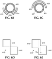
- skived proximal bond first section 615 extends less than 360° (preferably approximately 180°) radially about the circumference of the catheter shaft 605 (as shown in the radial cross-sectional view of Figure 6B ) and the skived proximal bond second section 620 extending less than 360° (preferably 180°) radially about the circumference of the catheter shaft 605 (as shown in the radially cross-sectional view in Figure 6C ).
- Skived proximal bond second section 620 preferably includes the proximal edge of the compliant inflatable balloon 630 and extends in a distal direction towards the skived proximal bond first section 615.
- Skived proximal bond first and second sections 615, 620 are radially offset relative to one another preferably with minimal or no radial overlap between contiguous bond sections (as clearly visible in Figure 6D representing the flattened skived proximal bond interface portion 610 of the compliant inflatable balloon of Figure 6A ).
- the skived proximal first section 615 covers radially 180° about the exterior surface of the catheter shaft 605, leaving exposed (uncovered) the remaining 180° of the catheter shaft 605.
- the radial cross-sectional view in Figure 6C shows the 180° exterior surface of the catheter shaft 605 exposed, i.e., not covered by the skived proximal second section 620 extending radially 180°.
- a biocompatible adhesive 633 is only applied to the exterior surface of the catheter shaft 605 in those regions covered by the respective skived proximal bond first and second sections 615, 620, as is illustrated in Figures 6B & 6C .
- the skived proximal bond first and second sections may be subject to thermal bonding or laser bonding.
- Figure 6A-6C shows each bond interface area (proximal and distal) comprising two skived sections, each extending 180° radially about the circumference of the catheter shaft. More than two skived sections are possible in each bond interface area such as three skived sections each extending 120° radially about the circumference of the catheter shaft; or four skived sections each extending 90° radially about the circumference of the catheter shaft.
- each of the skived proximal and distal bond interface areas may include a non-skived third radial section 618 extending 360° radially about the exterior surface of the catheter shaft.
- the non-skived third radial section 618 may be disposed in an axial/longitudinal direction between the skived first and second radial sections 615, 620 each extending radially 180° about the circumference of the catheter shaft.
- Figure 6E represents the flattened proximal bonding area 610' of the compliant inflatable balloon with this alternative design.
- the axial length "AL" of the non-skived third radial section 618 is so small (e.g., less than or equal to approximately 0.5 mm), representing a negligible increase in outer profile or outer diameter of the assembled catheter having no discernible negative impact during use of the catheter. Accordingly, the non-skived third radial section 618 provides an enhanced 360° radial bond between the compliant inflatable balloon and exterior surface of the catheter shaft with negligible enlargement of the outer profile or outer diameter of the assembled catheter. Positioning or arrangement of the non-skived third radial section extending 360° about the exterior surface of the catheter shaft may be varied.
- the skived first and second radial sections may be contiguous to one another, with the non-skived third radial section arranged contiguous with the free edge of either one of the skived first or second radial sections.
- These radially staggered or offset skived sections of each of the proximal and distal bond interface areas minimize the outer profile or outer diameter of the assembled catheter while cumulatively maintaining a secure bond 360° about the exterior surface of the catheter shaft.
- a non-inverted bond between the balloon and exterior surface of the catheter shaft may be subject to thermal, laser, and/or mechanical bonding.
- a heat shrink sleeve may be disposed about the exterior surface of the balloon sleeve and subject to thermal or laser bonding.
- a mechanical device e.g., a band, preferably a marker band
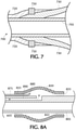
- Figure 7 is a partial cross-sectional longitudinal view of a configuration in which the proximal bond interface area of the balloon 730 (e.g., compliant, semi-compliant, or non-compliant) and the exterior surface of the catheter shaft 705 is subject to both thermal bonding (e.g., heat shrink of reflow sleeve/jacket 720) and mechanical bonding (e.g., physically crimped metal marker band 750) .
- thermal bonding e.g., heat shrink of reflow sleeve/jacket 720
- mechanical bonding e.g., physically crimped metal marker band 750
- the catheter Prior to introduction into the body, the catheter is first "prepped” by exhausting any residual air from the compliant inflatable balloon.
- a vent or exhaust tube 875 is a separate component from that of the catheter shaft 805.
- the diameter of the vent or exhaust tube 875 is selected to prevent the passage of the inflation fluid (e.g., contrast saline solution) therethrough, permitting only the residual air to be purged or exhausted.
- Factors to be taken into consideration when selecting the diameter of the vent or exhaust tube include the pressure in the balloon and the inflation fluid in the balloon (e.g., ratio of the mix of contrast and saline).
- the vent or exhaust tube 875 is secured between an exterior surface of the catheter shaft 805 and the balloon 830 (beneath either the proximal or distal bond interface area) using an adhesive 833.
- a discharge port or outlet 880 of the vent tube 875 is disposed within a cavity defined by the balloon 830 and the exterior surface of the catheter shaft 805.
- Prepping of the balloon 830 i.e., purging of the residual air from the balloon is accomplished by injecting an inflation fluid (e.g., contrast saline solution) into the balloon 830 via an inflation lumen 890 in the wall of the catheter shaft causing the residual air to be exhausted via the vent or exhaust tube 875 without the need for applying a vacuum.
- an inflation fluid e.g., contrast saline solution
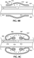
- FIGS 8B & 8C illustrate a compliant inflatable balloon 830' secured via a biocompatible adhesive 833 to the exterior surface of the catheter shaft 805' via non-inverted proximal and distal bonds 886, 887, respectively (i.e., bonds formed between an interior surface of the compliant inflatable balloon and an exterior surface of the catheter shaft).
- the vent or exhaust hole 876 in the compliant inflatable balloon 830' in the example depicted in Figures 8B & 8C is located proximate and distally of the non-inverted proximal bond 886.
- the location of the vent or exhaust hole 876 is such that with continued inflation of the compliant inflatable balloon 830' that portion of the compliant inflatable balloon having the vent hole 876 defined therein extends over the non-inverted proximal bond 876 and physically contacts the exterior surface of the catheter shaft 805' thereby sealing the vent hole prohibiting the passage of the inflation fluid therethrough.
- an inflation fluid is injected via an inflation lumen 890 defined in an exterior wall of the catheter shaft 805' causing the compliant inflatable balloon 830' to expand and residual air therein to exit through the vent hole 876.
- Figures 8D & 8E show yet another possible catheter configuration for purging of residual air via a vent or exhaust hole 876' in a compliant inflatable balloon 830" secured via a biocompatible adhesive 833' to the exterior surface of the catheter shaft 805" via inverted proximal and distal bonds 886', 887' (i.e., bonds formed between the inverted proximal and distal portions of the compliant inflatable balloon and exterior surface of the catheter shaft).
- the vent or exhaust hole 876' is depicted proximate and distally of the inverted proximal bond between the compliant inflatable balloon 830" and exterior surface of the catheter shaft 805".
- the location of the vent or exhaust hole 876' is such that with continued inflation that portion of the compliant inflatable balloon 830" having the vent hole defined therein extends over the inverted proximal bond 886' and physically contacts the exterior surface of the catheter shaft 805" thereby sealing the vent hole prohibiting the passage of the inflation fluid therethrough.
- the inflation fluid is injected through the inflation lumen 890' defined in an exterior wall of the catheter shaft causing the compliant inflatable balloon 830" to inflate and residual air to exit through the vent hole 876' defined in the balloon.
Landscapes
- Health & Medical Sciences (AREA)
- Life Sciences & Earth Sciences (AREA)
- Heart & Thoracic Surgery (AREA)
- Biomedical Technology (AREA)
- Veterinary Medicine (AREA)
- Public Health (AREA)
- General Health & Medical Sciences (AREA)
- Animal Behavior & Ethology (AREA)
- Engineering & Computer Science (AREA)
- Hematology (AREA)
- Anesthesiology (AREA)
- Pulmonology (AREA)
- Biophysics (AREA)
- Child & Adolescent Psychology (AREA)
- Vascular Medicine (AREA)
- Surgery (AREA)
- Orthopedic Medicine & Surgery (AREA)
- Nuclear Medicine, Radiotherapy & Molecular Imaging (AREA)
- Medical Informatics (AREA)
- Molecular Biology (AREA)
- Media Introduction/Drainage Providing Device (AREA)
Abstract
Description
- During capture and retrieval of a thrombus, occlusion, or clot in a vessel using an intravascular catheter a with a balloon may be employed to arrest blood flow or dilate the vessel. The balloon is secured to the catheter shaft of the present inventive balloon guide catheter at a bonding interface area(s) having a minimized outer profile/diameter and optimized bond strength.
- Acute ischemic stroke is primarily caused by a thrombotic or embolic occlusion (e.g., blockage) in an artery of the brain. The occlusion is typically caused by a blood clot liberated from another part of the body which travels in an antegrade direction (in the direction of normal blood flow) through the vessel and eventually becomes lodged in a neurovascular artery, where it obstructs blood flow to a region of the brain.
- A procedure known as a thrombectomy may be used to remove the thrombus, occlusion, blockage or clot lodged in the vessel using a mechanical retrieval device. During the thrombectomy procedure or treatment a physician or interventionalist endovascularly introduces a guidewire and microcatheter together through the vasculature, typically in an artery located in the groin or the arm or by direct access through the carotid artery. Together the guidewire and microcatheter are advanced to a location facing a proximal side of the targeted clot, blockage or occlusion. Then the guidewire is advanced across the clot, followed by the microcatheter. While in a compressed state, a mechanical thrombectomy device may be guided through the lumen of the microcatheter to the target site. Upon emerging from the microcatheter the mechanical thrombectomy device typically automatically expands to its original enlarged state. Mechanical thrombectomy devices are typically made of a selfexpanding biocompatible material such as nickel-titanium. Aspiration through the catheter may accompany or be used in place of the mechanical retrieval device to remove the clot.
- During a thrombectomy procedure balloon guide catheters are often employed to arrest blood flow by introducing an inflation fluid into a compliant inflatable balloon (rather than inflating via pressure) made of an elastomeric material, for example, polyurethane, polyblend, or latex. Its ability to conform to the shape of the vasculature makes the compliant inflatable balloon particularly suited for use in arresting of blood flow. In other applications such as dilating of a vessel or opening an occlusion, balloon guide catheters may employ a non-compliant or semi-compliant balloon that is inflated by pressure, rather than using an inflation fluid. Specifically, non-compliant balloons typically made of polyester or nylon when inflated at a high pressure dilate a vessel or open an occlusion; whereas semi-compliant balloons made of material such as Pebax or higher durometer polyurethanes when inflated in pressure are more compliant than that of non-compliant balloons providing greater flexibility during delivery. Regardless of the type of balloon (compliant, semi-compliant, or non-compliant), bonding of the balloon to the exterior surface of the catheter shaft during manufacture has two competing criteria, i.e., minimization of the outer profile/diameter at the bonding interface area(s) in which the balloon is mounted to the catheter shaft while maximizing bond strength and integrity.
- It is desirable to design an improved balloon guide catheter having a bonding interface area between the balloon and exterior surface of the catheter shaft to achieve optimum bond strength and integrity while minimizing outer profile or outer diameter.
- An aspect of the present invention is directed to an improved balloon guide catheter to which a balloon (compliant, semi-compliant, or non-compliant) is bonded thereto with maximized bonding strength and integrity while minimizing outer profile or outer diameter.
- Another aspect of the present invention relates to a balloon guide catheter with a catheter shaft having defined longitudinally therein a central lumen and an inflation lumen substantially parallel to the central lumen; the catheter shaft having a braid supporting the central lumen and the inflation lumen. A balloon is disposed about the braid. At least one reflow jacket made of a material reflowable into the braid secures the balloon to the catheter shaft, wherein an exposed portion of the balloon is not covered by the at least one reflow jacket.
- Still another aspect of the present invention is directed to a balloon guide catheter including a catheter shaft and a balloon disposed about the catheter shaft. The balloon is secured to the catheter shaft at a distal bond interface area and an opposite proximal bond interface area, wherein the balloon has a plurality of radially arranged apertures and/or recesses defined in each of the distal and proximal bond interface areas of the balloon. Adhesive disposed about the exterior surface of the catheter shaft is seepable upwards into the plural radially arranged apertures and/or recesses in the balloon.
- While still another aspect of the present invention relates to a balloon guide catheter including a catheter shaft having an exterior surface and a balloon disposed about the exterior surface of the catheter shaft. The balloon has an inverted distal bonding interface area including an inverted distal edge and/or an opposite inverted proximal bonding interface area including a proximal edge. The inverted distal bonding interface area and/or the inverted proximal bonding interface area of the balloon is secured via an adhesive to the exterior surface of the catheter shaft.
- Yet another aspect of the present invention is directed to a balloon guide catheter including a catheter shaft and a balloon sleeve disposed about the catheter shaft. The balloon is secured to the catheter shaft at a skived distal bond interface area and/or an opposite skived proximal bond interface area. The skived distal bond interface area and/or the skived proximal bond interface area of the balloon is secured to the catheter shaft via an adhesive.
- Another aspect of the present invention is directed to a balloon guide catheter including a catheter shaft having an exterior surface and a balloon disposed about the catheter shaft. The balloon is secured to the catheter shaft, with a vent tube secured between the compliant inflatable tube and the exterior surface of the catheter shaft.
- A further aspect of the present invention relates to a balloon guide catheter including a catheter shaft and a balloon disposed about the catheter shaft. The balloon is secured to the catheter shaft at a distal bond interface area and an opposite proximal bond interface area; wherein the balloon has an exhaust hole defined therein between the proximal and distal bond interface areas. The balloon is transitionable to an expanded state with a portion of the balloon extendible over at least one of the respective proximal and distal bond interface areas in physical contact with an exterior surface of the catheter shaft sealing the exhaust hole.
- The foregoing and other features of the present invention will be more readily apparent from the following detailed description and drawings illustrative of the invention wherein like reference numbers refer to similar elements throughout the several views and in which:
-
Figure 1A is a partial axial cross-sectional view of a first configuration of the present inventive balloon guide catheter in which distal and proximal edges of a compliant inflatable balloon sleeve (depicted in a non-inflated state) are secured beneath respective distal and proximal reflow jackets/sleeves separated axially from one another to form a 360° radial gap therebetween exposing a portion of the compliant inflatable balloon sleeve; -
Figure 1B is a radial cross-sectional view along lines I(B)-I(B) inFigure 1A through the proximal reflow jacket/sleeve securing the proximal edge of the of the compliant inflatable balloon sleeve to the exterior surface of the catheter shaft; -
Figure 1C is a radial cross-sectional view along lines I(C)-I(C) inFigure 1A through the distal reflow jacket/sleeve securing the distal edge of the of the compliant inflatable balloon sleeve to the exterior surface of the catheter shaft; -
Figure 2A a partial axial cross-sectional view of another configuration of the present inventive balloon guide catheter in which a compliant inflatable balloon (depicted in a non-inflated state) is secured beneath a single reflow jacket/sleeve having a cut-out or opening defined therein exposing a portion of the compliant inflatable balloon; -
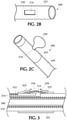
Figure 2B is a top view of the balloon guide catheter ofFigure 2A , wherein the compliant inflatable balloon is in a non-inflated state; -
Figure 2C is a distal perspective view of the balloon guide catheter ofFigure 2B , wherein the compliant inflatable balloon is in an inflated state, protruding radially outward through the cut-out or opening defined in the single reflow jacket/sleeve; -
Figure 3 is a partial longitudinal cross-sectional view of still another configuration of the present inventive balloon guide catheter in which a braid configured as afigure "8 " (woven above and below the inflation lumen as well as encompassing the central lumen) terminates proximally of the distal end of the inflation lumen so as not to coincide with the single reflow jacket/sleeve thereby minimizing the outer profile; -
Figure 4A is a partial side view of a proximal bond interface area of a complaint inflatable balloon having a plurality of radial slits defined therein, wherein the balloon is illustrated in an inflated state; -
Figure 4B is a partial proximal end perspective view of the compliant inflatable balloon ofFigure 4A ; -
Figure 4C is a partial side view of a proximal bond interface area of a complaint inflatable balloon having a plurality of radially arranged holes defined therein, wherein the balloon is illustrated in an inflated state; -
Figure 4D is a longitudinal cross-sectional view of the compliant inflatable balloon ofFigure 4A assembled to a catheter shaft; -
Figure 5A is a partial longitudinal cross-sectional view of a prior art balloon guide catheter having a compliant inflatable balloon sleeve secured along non-inverted proximal and non-inverted distal bond interface areas thereof to the exterior surface of the catheter shaft using an adhesive; -
Figure 5B is a partial longitudinal cross-sectional view of a present inventive balloon guide catheter having a compliant inflatable balloon sleeve secured along an inverted proximal bond interface area and an inverted distal bond interface area to the exterior surface of the catheter shaft using an adhesive; -
Figure 5C is a partial longitudinal cross-sectional view of a present inventive balloon guide catheter having a compliant inflatable balloon sleeve secured along a non-inverted proximal bond interface area and an inverted distal bond interface area to the exterior surface of the catheter shaft using an adhesive; -
Figure 6A is a partial side view of yet another configuration of the present inventive balloon guide catheter illustrating a skived proximal bond interface area of the compliant inflatable balloon sleeve including a skived proximal bond first section extending less than 360° (preferably approximately 180°) radially about the circumference of the catheter shaft and a skived proximal bond second section extending less than 360° (preferably approximately 180°) radially about the circumference of the catheter shaft; -
Figure 6B is a radial cross-sectional view through the skived proximal bond first section of the skived proximal bond interface area of the compliant inflatable balloon ofFigure 6A along lines VI(B) - VI(B); -
Figure 6C is a radial cross-sectional view through the skived proximal bond second section of the skived proximal bond interface area of the compliant inflatable balloon ofFigure 6A along lines VI(C) - VI(C); -
Figure 6D represents the flattened skived proximal bond interface area of the compliant inflatable balloon ofFigure 6A ; -
Figure 6E represents an alternative design of the flattened skived proximal bond interface area of the compliant inflatable balloon that includes: (i) a skived proximal bond first section extending less than 360° (preferably approximately 180°) radially about the circumference of the catheter shaft; (ii) a skived proximal bond second section extending less than 360° (preferably approximately 180°) radially about the circumference of the catheter shaft; and (iii) disposed between the skived proximal bond first and second sections a non-skived proximal bond third section extending 360° radially about the circumference of the catheter shaft; -
Figure 7 is a partial longitudinal cross-sectional view of a marker band physically crimped about the proximal reflow jacket/sleeve securing beneath the proximal edge of the compliant inflatable balloon sleeve to the exterior surface of the catheter shaft; -
Figure 8A is a partial longitudinal cross-sectional view of a compliant inflatable balloon with a longitudinal vent tube secured between the proximal bond interface area of the compliant inflatable balloon and the exterior surface of the catheter shaft, wherein the balloon is illustrated in an inflated state; -
Figure 8B is a partial longitudinal cross-sectional view of a compliant inflatable balloon with a vent hole defined therein located proximate the non-inverted proximal bond interface area of the compliant inflatable balloon secured to the exterior surface of the catheter shaft, wherein the compliant inflatable balloon is depicted in a partially inflated state; -
Figure 8C is a partial longitudinal cross-sectional view of the compliant inflatable balloon ofFigure 8B in a further inflated state depicting a portion of the compliant inflatable balloon extending in a proximal direction over the non-inverted proximal bond interface area and physically contacting the exterior surface of the catheter shaft sealing the vent hole and prohibiting inflation fluid from exiting therethrough; -
Figure 8D is a partial longitudinal cross-sectional view of another configuration of the compliant inflatable balloon with a vent hole defined therein located proximate an inverted proximal bond interface area in which the compliant inflatable balloon is secured to the exterior surface of the catheter shaft, wherein the balloon is depicted in a partially inflated state; and -
Figure 8E is a partial longitudinal cross-sectional view of the compliant inflatable balloon ofFigure 8D in a further inflated state depicting a portion of the compliant inflatable balloon extending in a proximal direction over the inverted proximal bond interface area and physically contacting the exterior surface of the shaft sealing the vent hole thereby prohibiting the inflation fluid from exiting therethrough. - The terms "distal" or "proximal" are used in the following description with respect to a position or direction relative to the treating physician or medical interventionalist. "Distal" or "distally" are a position distant from or in a direction away from the physician or interventionalist. "Proximal" or "proximally" or "proximate" are a position near or in a direction toward the physician or medical interventionalist. The terms "occlusion", "clot" or "blockage" are used interchangeably.
- The present invention is directed to several different features, designs and configurations for an intravascular catheter with a balloon for arresting blood flow through or dilating a vessel, wherein the integrity and strength of the bond between the balloon secured to the catheter shaft is optimized while the outer profile/diameter is minimized. By way of illustrative example, the present inventive balloon guide catheter is shown and described with a compliant inflatable balloon. It is, however, within the intended scope of the present invention for the present inventive balloon guide catheter to employ any type of balloon (compliant, semi-compliant, or non-compliant).
- The compliant inflatable balloon may be a sleeve or patch secured or trapped to the exterior surface of the catheter shaft beneath one or more reflow jackets or sleeves.
Figures 1A-1C represent a first design of the present inventive balloon guide catheter in which opposite edges of a compliantinflatable balloon sleeve 130 are secured or trapped to an exterior surface of acatheter shaft 105 by separate respective reflow jackets/sleeves balloon guide catheter 100 in accordance with this first configuration is shown inFigure 1A . Acatheter shaft 105 includes an inner liner or lining 107 forming an axially extendingcentral lumen 106. Arranged radially outward and encompassing the inner liner or lining 107 is a supporting layer 110 (e.g., braid, mesh, cage or hypotube) providing support and kink resistance to thecentral lumen 106 andinflation lumen 115 extending substantially parallel thereto. In the example illustrated in the figures, the supporting layer is abraid 110. Preferably,braid 110 encircles thecentral lumen 106 as well as being woven above and below theinflation lumen 115 in afigure "8 " configuration, as shown in the radial cross-sectional view ofFigure 1B .Braid 110 encircles the entire length of the central lumen 106 (Figure 1C ). A compliantinflatable balloon sleeve 130 having aproximal edge 135 arranged proximally of and opposite that of adistal edge 140 is disposed about thebraid 110 of thecatheter shaft 105. - Two reflow jackets or sleeves are disposed about the catheter shaft. Specifically, a distal reflow jacket/
sleeve 125 is arranged distally of and separated a predetermined distance in an axial direction from a proximal reflow jacket/sleeve 120 defining a 360°radial gap 116 therebetween. The proximal and distal reflow jackets/sleeves distal edges inflatable balloon sleeve 130 while a central radial portion of the compliantinflatable balloon sleeve 130 remains exposed through the 360°radial gap 116. In the exemplary embodiment depicted inFigure 1A , a single proximal reflow jacket/sleeve 120 is disposed radially outward of so as to cover theproximal edge 135 of the compliantinflatable balloon sleeve 130, while a single distal reflow jacket/sleeve 125 is disposed radially outward of so as to cover thedistal edge 140 of the compliantinflatable balloon sleeve 130. Multiple proximal reflow jackets/sleeves may be arranged a top one another in a radially outward direction covering theproximal edge 135 of the compliantinflatable balloon sleeve 130 and reflowed onto (embedded within) thebraid 110, while multiple distal reflow jackets/sleeves may be arranged a top one another in a radially outward direction covering thedistal edge 140 of the compliantinflatable balloon sleeve 130 and reflowed onto (embedded within) thebraid 110. In such circumstance of multiple reflow jackets/sleeves covering each of the proximal and distal edges of the compliant inflatable balloon, each reflow jacket/sleeve may be independently reflowed with each reflow jacket/sleeve positioned and heated sequentially one a top the other. That is, the first or inner reflow jackets/sleeves (proximal and distal) after being positioned about the respective proximal and distal edges of the compliant inflatable balloon is heated to reflow onto (embed within) thebraid 110. Thereafter, the second or outer reflow jackets/sleeves (proximal and distal) after being positioned about the corresponding first reflow jackets/sleeves is heated to reflow onto. Otherwise, a single reflow process may be employed whereby both the first (inner) and second (outer) reflow jackets/sleeves once positioned are simultaneously subjected to heat at the same time causing the material to reflow. - During assembly, the compliant
inflatable balloon sleeve 130 is positioned about thecatheter shaft 105. Thereafter, proximal and distal reflow jackets/sleeves inflatable balloon sleeve 130 so as to cover the respective proximal anddistal edges inflatable balloon sleeve 130 remains exposed through the 360°radial gap 116. During reflow, a protective covering (e.g., band) is positioned at least covering the 360°radial gap 116 to protect the exposed portion of the compliant inflatable balloon sleeve 130 (i.e., that portion of the compliant inflatable balloon sleeve not covered by a reflow jacket/sleeve) from exposure to heat during the reflow process. Preferably, the protective covering extends beyond the balloon, for example, a protective covering sleeve extending in an axial direction beyond the proximal and distal edges on both sides of the compliant inflatable balloon. The protective covering is preferably a heat resistant material such as heat shrink material (e.g., Polyethylene terephthalate (PET), Fluorinated ethylene propylene (FEP)) the nature of which ensures that it is remains in place. A non-heat shrinkable material (e.g., Polytetrafluoroethylene (PTFE), Polyether ether ketone (PEEK)) may be used as the protective covering which is secured in place, for example, via an outer band or sleeve made of heat shrinkable material. The assembled catheter shaft is then subject to heat using thermal and/or laser light causing the proximal and distal reflow jackets/sleeves distal edges inflatable balloon 130 creating a leakproof seal with thebraid 110 of thecatheter shaft 105. After reflow, the protective covering is removed. Injection of a biocompatible inflation fluid (e.g., contrast saline solution) via theinflation lumen 115 causes the compliant inflatable balloon to expand only within the 360°radial gap 116. Hence, a 360° radial inflated bulge (e.g., tire) of the compliant inflatable balloon is produced in the 360°radial gap 116 between the proximal and distal reflow jackets/sleeves -
Figures 2A-2C depict a slight variation from the previously described configuration of the present inventive balloon guide catheter illustrated inFigures 1A-1C . Rather than two (e.g., proximal and distal) reflow jackets/sleeves separated axially to define a 360° radial gap, a single reflow jacket/sleeve 223 is employed having a cut-out or opening 216 defined therein that extends radially less than 360° (e.g., side opening). A partial longitudinal cross-sectional view of theballoon guide catheter 200 in accordance with this modified configuration is shown inFigure 2A . Acatheter shaft 205 includes an inner liner or lining 207 forming an axially extendingcentral lumen 206. Arranged radially outward and encompassing the inner liner or lining 207 is a supporting layer 210 (e.g., braid, mesh, cage or hypotube) supporting both thecentral lumen 206 andinflation lumen 215 arranged substantially parallel to one another. In the example illustrated in the figures, the supporting layer is abraid 210 similar in configuration to that inFigures 1A-1C . A compliantinflatable balloon patch 230 having a perimeter is placed over thebraid 210 of thecatheter shaft 205. A single reflow jacket orsleeve 223 has defined therein a cut-out oropening 216 extending less than 360° radially that is substantially aligned with the compliantinflatable balloon patch 230. The cut-out oropening 216 is sized to be smaller in dimension than the perimeter of the compliantinflatable balloon patch 230 exposing only a portion of the balloon patch therethrough. A rectangular shape cut-out oropening 216 is illustrated, but any desired shape may be used such as, but not limited to, a square, a circle, or an oval.Figure 2B is a top view of the assembledballoon guide catheter 200 depicting the cut-out or opening 216 in the single reflow jacket/sleeve 223 exposing a portion of the compliant inflatable balloon 230 (shown in a non-inflated state - the outer perimeter of which is denoted by dashed lines). Injection of the biocompatible inflation fluid (e.g., contrast saline solution) via theinflation lumen 215 causes the secured compliantinflatable balloon 230 to expand only within the cut-out oropening 216. Hence, an inflated "side" bulge (i.e., "side inflation bulge" extending radially less than 360°) of the compliant inflatable balloon is produced in the cut out or opening 216 of the reflow jacket/sleeve 223. Once the catheter is inserted in a vessel at a target site the balloon is inflated producing an offset inflated ("side bulge) arresting blood flow therethrough with minimal increase to the outer profile or outer diameter of the assembled catheter. - In the reflow jacket/sleeve configurations illustrated and described above in
Figures 1A-1C as well asFigures 2A-2C , each of the central lumen and inflation lumen is supported by the braid 210 (e.g., supporting layer) extending to their respective distal ends. Referring toFigure 1A ,braid 110 supports (i.e., woven above and below) theinflation lumen 115 to its distal end (e.g., discharge port) coinciding with the 360°radial gap 116 between the two separated distal and proximal reflow jackets/sleeves Figure 2A ,braid 210 supports (i.e., woven above and below) theinflation lumen 215 to its distal end (e.g., discharge port) coinciding with the cut-out or opening 216 defined in the single reflow jacket/sleeve 223. In either design, such support provided by the braid extending to the distal end of the inflation lumen undesirably increases the overall outer profile (outer diameter) at the proximal interface bond area of the compliant inflatable balloon secured to the reflow jacket/sleeve. - Referring to the exemplary partial longitudinal cross-sectional view in
Figure 3 , the supporting layer (e.g., a braid 310) once again is arranged in the shape of afigure "8 " (i.e., wound about thecentral lumen 306 as well as above and below the inflation lumen 315). In order to reduce the overall profile by the radial thickness of the braid, inFigure 3 a portion of the distal end of theinflation lumen 315 starting from the discharge port 312 (distal tip or end) and extending in a proximal direction to a proximal edge of the single reflow sleeve/jacket 323 is free from (not supported by) the braid 310 (e.g., supporting layer). That is, the shortening in a distal direction of the "over" braid 310 (i.e., braid woven above and below the inflation lumen) so that it does not coincide (i.e., stops prior to or upon reaching) with the single reflow jacket/sleeve 323. Note that the embodiment illustrated is that of asingle reflow 323 jacket/sleeve having a cut-out or opening 316 defined therein; however, this feature of the inflation lumen being unsupported where it coincides with the reflow jacket/sleeve is also suited to the design employing two reflow jackets/sleeves separated from one another to form a 360° radial gap therebetween (as depicted inFigures 1A-1C ). Accordingly, in either design (e.g., the single reflow jacket/sleeve having a single side opening or two reflow jackets/sleeves separated axial to form a 360° radial gap therebetween), in the area that coincides with the reflow jacket/sleeve, theinflation lumen 315 is not supported by the braid 310 (i.e.,braid 310 is not woven above and below the inflation lumen) thereby minimizing the overall outer profile (outer diameter) of the assembled balloon guide catheter. Unlike theinflation lumen 315,central lumen 306 is preferably supported from the proximal to the distal end by thebraid 310. - Improved wettability and bond strength may be attained by defining a plurality of apertures (radial slits, holes or other geometric shapes) and/or recesses (indents) arranged radially in each of the proximal and distal bond interface areas of the compliant inflatable balloon secured to the exterior surface of the catheter shaft.
Figures 4A & 4B are respective side and perspective views of the proximal end of the compliant inflatable balloon sleeve (shown in an inflated state) having a plurality of apertures (e.g., radial slits 401) defined therethrough in the proximal bond interface area 487 (the distal bond interface area having similar plural apertures defined therein). The shape of each aperture may be a radial slit 401 (as shown inFigures 4A & 4B ), a circular hole 401' (Figure 4C ) or any other geometric shape defined through the balloon. All of the plural apertures may have the same shape and size, but different shapes and/or variation in size is also possible. Any number of one or more rows of radially arranged apertures may be provided wherein adjacent rows may be either offset or aligned radially from one another. - Prior to assembly, the plurality of apertures is made in the respective proximal and distal bond interface areas of the compliant
inflatable balloon sleeve 430 using drilling, burning, laser etching, etc. Thereafter, while in a non-inflated state, the compliantinflatable balloon 430 sleeve is positioned about the exterior surface of thecatheter shaft 405. Respective proximal and distal edges of the compliantinflatable balloon 430 are rolled toward one another exposing the exterior surface of thecatheter shaft 405 beneath.Biocompatible adhesive 433 is applied about the exposed exterior surface of thecatheter shaft 405, whereupon the proximal and distal edges of the compliantinflatable balloon 430 are unfurled over the applied biocompatible adhesive 433 seeping or oozing upwards through theapertures 401 defined through the compliantinflatable balloon 430, as shown in longitudinal cross-sectional view inFigure 4D . It is also possible that the adhesive 433 may ooze or seep beyond the radial thickness of the apertures and onto the exterior surface of the compliantinflatable balloon sleeve 430 in areas adjacent to the apertures. In the configuration depicted inFigures 4A-4C a plurality of apertures (e.g., radial slits or circular holes) is defined through the compliant inflatable balloon (extending from the interior surface to the outer surface of the balloon). Alternatively, the compliant inflatable balloon may be designed to have a plurality of recesses (indents) defined along the interior surface of the compliant inflatable balloon (without extending through to (closed off at) the exterior surface of the compliant inflatable balloon). Recesses may be sufficient to allow the adhesive to pool therein, but since they are closed off at the exterior surface of the compliant inflatable balloon prevent the adhesive from flowing on to the exterior surface. In yet another possible configuration, a combination of apertures and recesses may be defined in the compliant inflatable balloon. The apertures and/or recesses may extend a predetermined length in a longitudinal direction to constrain/limit/control the bond length/size by virtue of the fact that the adhesive flows/pools into them. Thus, during manufacture pooling of the adhesive only within the apertures and/or recesses allows the bond length to be controlled without increasing the bond outer profile. - Another aspect of the present inventive balloon guide catheter is to maintain integrity and maximize strength of the bond created between the compliant inflatable balloon and the exterior surface of the catheter shaft. Diminished bond integrity possibly resulting in failure due to peel back of the secured proximal and/or distal edges of the compliant inflatable balloon sleeve when inflated is problematic.
Figure 5A shows a prior art conventional non-inverted adhesive bond of a compliant inflatable balloon sleeve to an exterior surface of the catheter shaft. When over inflated a compliant balloon may grow or expand over the conventional non-inverted bonds resulting in possible unwanted peel back along such bonds. To minimize the occurrence of peel back during inflation, the present inventive compliant inflatable balloon sleeve is preferably adhered to the exterior surface of the catheter shaft via an inverted bond along the proximal edge, distal edge or both edges. As a result of the inverted bond, any growth of the compliant inflatable balloon as a result of over inflation will prevent peel back.Figure 5B is an exemplary configuration of a compliantinflatable balloon sleeve 530 in which both the proximal and distal edges thereof are inverted (e.g., retracted, flipped, folded, or bent inward) prior to being secured to the exterior surface of thecatheter shaft 505 via abiocompatible adhesive 533. Whereas,Figure 5C is an alternative configuration wherein only a single edge (e.g., the distal bond or the proximal bond) of the compliantinflatable balloon sleeve 530 is inverted (e.g., flipped, folded inward) prior to being secured to the exterior surface of thecatheter shaft 505 viaadhesive 533. In both configurations (Figures 5B &5C ), during assembly initially positioned about the exterior surface of the catheter shaft the compliantinflatable balloon sleeve 530 has an interior/inner surface (facing radially inwards towards the catheter shaft) and an exterior/outer surface (facing radially outwards away from the catheter shaft). Next, a proximal portion (including the proximal edge) and/or a distal portion (including the distal edge) of the compliantinflatable balloon sleeve 530 is inverted, flipped, folded, tucked, bent, or retracted inwards onto itself, whereupon the inverted, flipped folded, tucked or retracted inwards portion (now facing radially inward towards the catheter shaft) is adhered to the exterior surface of the catheter shaft forming an inverted bond. The two opposing inverted portions of the compliant inflatable balloon sleeve are referred to as a proximal inverted bond interface area and a distal inverted bond interface area, each of which is secured via adhesive to the exterior surface of the catheter shaft forming an inverted proximal bond and an inverted distal bond, respectively. Preferably, the inverted proximal bond interface area of the compliant inflatable balloon includes the proximal edge and is approximately 1mm in length in an axial direction, whereas the inverted distal bond interface area of the compliant inflatable balloon includes the distal edge and is approximately 1mm in length in an axial direction. Any desired length in an axial direction of each inverted bond interface area (proximal or distal) may be selected depending on a desired outer profile or outer diameter of the assembled catheter. That is, the shorter the axial length of the inverted bond interface area (proximal or distal) the greater the outer profile or outer diameter. The length in an axial direction of each inverted bond interface area (proximal or distal) may, but need not necessarily be, the same. Purging of residual air from the balloon may be accomplished in different ways. One method is to have a vent or exhaust hole in the balloon proximate the inverted bond, whereupon the balloon as it inflates expands outward over the vent hole forming a seal. Other prepping steps for purging residual air may be employed such as repeatedly inflating/deflating the balloon (typically while holding the catheter so that the balloon is pointing downwards and sometimes flicking of the balloon) until sufficient residual air is exhausted. - As depicted by the downward arrows illustrated in
Figure 5B &5C , over inflation causes the compliant inflatable balloon sleeve to grow as the pressure therein increases imposing a downward force on the inverted bond interface area (distal and/or proximal) pushing the inverted portions of the balloon against the exterior surface of the catheter shaft thereby minimizing peel back. Such inverted bond configuration enhances the integrity of the bond with negligible increase in outer profile or outer diameter of the assembled catheter. Moreover, intended positioning the distal inverted bond proximate the distal tip of the catheter may advantageously cause the inflated compliant balloon to protrude distally beyond the distal tip of the catheter, particularly suited for certain treatments. The compliant inflatable balloon when extending over or beyond the distal tip of the catheter may provide protection during delivery as the flexible, compliant balloon material is now the leading edge rather than the harder, less flexible, less compliant material of the catheter shaft. Furthermore, if aspiration through the main guidewire lumen of the catheter is employed during clot retrieval then the inflated portion of the balloon extending beyond the distal tip acts as a funnel guiding the clot into the main lumen of the shaft minimizing shearing of the clot, blockage or occlusion. - Still another configuration calls for a skived bonding interface area of the compliant inflatable balloon with an exterior surface of the catheter shaft. By way of illustrative example, the balloon depicted in
Figure 6A is a compliant inflatable balloon, however, this configuration is suited for other type balloons (e.g., semi-compliant, or non-compliant). Compliantinflatable balloon sleeve 630 is secured to the exterior surface of thecatheter shaft 605 along a skived proximal bond interface area 610 (shown in the side view ofFigure 6A ) and/or an opposite skived distal bond interface area (the mirror opposite of that depicted inFigure 6A ), wherein each of the skived proximal and/or distal bond interface areas are skived at a right angle (in an axial/longitudinal direction). Skived proximalbond interface area 610 of the exemplary compliantinflatable balloon sleeve 630 shown inFigure 6A is split into two sections, namely, a skived proximal bondfirst section 615 disposed distally of a skived proximal bondsecond section 620. Specifically, the skived proximal bondfirst section 615 extends less than 360° (preferably approximately 180°) radially about the circumference of the catheter shaft 605 (as shown in the radial cross-sectional view ofFigure 6B ) and the skived proximal bondsecond section 620 extending less than 360° (preferably 180°) radially about the circumference of the catheter shaft 605 (as shown in the radially cross-sectional view inFigure 6C ). Skived proximal bondsecond section 620 preferably includes the proximal edge of the compliantinflatable balloon 630 and extends in a distal direction towards the skived proximal bondfirst section 615. Skived proximal bond first andsecond sections Figure 6D representing the flattened skived proximalbond interface portion 610 of the compliant inflatable balloon ofFigure 6A ). Referring to the radial cross-sectional view inFigure 6B , the skived proximalfirst section 615 covers radially 180° about the exterior surface of thecatheter shaft 605, leaving exposed (uncovered) the remaining 180° of thecatheter shaft 605. Likewise, the radial cross-sectional view inFigure 6C shows the 180° exterior surface of thecatheter shaft 605 exposed, i.e., not covered by the skived proximalsecond section 620 extending radially 180°. Abiocompatible adhesive 633 is only applied to the exterior surface of thecatheter shaft 605 in those regions covered by the respective skived proximal bond first andsecond sections Figures 6B & 6C . To further enhance the bond, the skived proximal bond first and second sections may be subject to thermal bonding or laser bonding. By way of example,Figure 6A-6C shows each bond interface area (proximal and distal) comprising two skived sections, each extending 180° radially about the circumference of the catheter shaft. More than two skived sections are possible in each bond interface area such as three skived sections each extending 120° radially about the circumference of the catheter shaft; or four skived sections each extending 90° radially about the circumference of the catheter shaft. - In a slight variation to that in
Figures 6A-6C , to further enhance the bond between balloon and catheter shaft, each of the skived proximal and distal bond interface areas may include a non-skived thirdradial section 618 extending 360° radially about the exterior surface of the catheter shaft. By way of illustrative example, the non-skived thirdradial section 618 may be disposed in an axial/longitudinal direction between the skived first and secondradial sections Figure 6E represents the flattened proximal bonding area 610' of the compliant inflatable balloon with this alternative design. The axial length "AL" of the non-skived thirdradial section 618 is so small (e.g., less than or equal to approximately 0.5 mm), representing a negligible increase in outer profile or outer diameter of the assembled catheter having no discernible negative impact during use of the catheter. Accordingly, the non-skived thirdradial section 618 provides an enhanced 360° radial bond between the compliant inflatable balloon and exterior surface of the catheter shaft with negligible enlargement of the outer profile or outer diameter of the assembled catheter. Positioning or arrangement of the non-skived third radial section extending 360° about the exterior surface of the catheter shaft may be varied. Instead of the being disposed between the skived first and second radial sections 615', 620' (as shown inFigure 6E ), the skived first and second radial sections may be contiguous to one another, with the non-skived third radial section arranged contiguous with the free edge of either one of the skived first or second radial sections. These radially staggered or offset skived sections of each of the proximal and distal bond interface areas minimize the outer profile or outer diameter of the assembled catheter while cumulatively maintaining a secure bond 360° about the exterior surface of the catheter shaft. - To further reduce the occurrence of peel back, as an alternative to the inverted bond configuration (shown in
Figures 5B &5C ), a non-inverted bond between the balloon and exterior surface of the catheter shaft may be subject to thermal, laser, and/or mechanical bonding. For example, a heat shrink sleeve may be disposed about the exterior surface of the balloon sleeve and subject to thermal or laser bonding. Still further enhancement of the integrity of the bond may be realized by a mechanical device (e.g., a band, preferably a marker band) physically crimped about the exterior surface of the heat shrink sleeve.Figure 7 is a partial cross-sectional longitudinal view of a configuration in which the proximal bond interface area of the balloon 730 (e.g., compliant, semi-compliant, or non-compliant) and the exterior surface of thecatheter shaft 705 is subject to both thermal bonding (e.g., heat shrink of reflow sleeve/jacket 720) and mechanical bonding (e.g., physically crimped metal marker band 750) . - Prior to introduction into the body, the catheter is first "prepped" by exhausting any residual air from the compliant inflatable balloon. Several different configurations for purging the residual air from the compliant inflatable balloon are contemplated. One possible design is illustrated in
Figure 8A wherein a vent orexhaust tube 875 is a separate component from that of thecatheter shaft 805. The diameter of the vent orexhaust tube 875 is selected to prevent the passage of the inflation fluid (e.g., contrast saline solution) therethrough, permitting only the residual air to be purged or exhausted. Factors to be taken into consideration when selecting the diameter of the vent or exhaust tube include the pressure in the balloon and the inflation fluid in the balloon (e.g., ratio of the mix of contrast and saline). The vent orexhaust tube 875 is secured between an exterior surface of thecatheter shaft 805 and the balloon 830 (beneath either the proximal or distal bond interface area) using an adhesive 833. A discharge port oroutlet 880 of thevent tube 875 is disposed within a cavity defined by theballoon 830 and the exterior surface of thecatheter shaft 805. Prepping of the balloon 830 (i.e., purging of the residual air from the balloon) is accomplished by injecting an inflation fluid (e.g., contrast saline solution) into theballoon 830 via aninflation lumen 890 in the wall of the catheter shaft causing the residual air to be exhausted via the vent orexhaust tube 875 without the need for applying a vacuum. - The need for a separate vent or exhaust tube may be eliminated altogether, instead residual air being purged via a vent hole defined in the compliant inflatable balloon.
Figures 8B & 8C illustrate a compliant inflatable balloon 830' secured via abiocompatible adhesive 833 to the exterior surface of the catheter shaft 805' via non-inverted proximal anddistal bonds exhaust hole 876 in the compliant inflatable balloon 830' in the example depicted inFigures 8B & 8C is located proximate and distally of the non-invertedproximal bond 886. Specifically, the location of the vent orexhaust hole 876 is such that with continued inflation of the compliant inflatable balloon 830' that portion of the compliant inflatable balloon having thevent hole 876 defined therein extends over the non-invertedproximal bond 876 and physically contacts the exterior surface of the catheter shaft 805' thereby sealing the vent hole prohibiting the passage of the inflation fluid therethrough. Referring toFigure 8B , during prepping of the catheter, an inflation fluid is injected via aninflation lumen 890 defined in an exterior wall of the catheter shaft 805' causing the compliant inflatable balloon 830' to expand and residual air therein to exit through thevent hole 876. Continued inflation causes that portion of the compliant inflatable balloon 830' having thevent hole 876 defined therein to extend over the non-invertedproximal bond 886 and physically contact the exterior surface of the catheter shaft 805', as shown inFigure 8C . The increased pressure within the compliant inflatable balloon causes inward radial expansion of the balloon towards the shaft imposing on the extended portion of the balloon a radially inward force sealing thevent hole 876 against the exterior surface of the catheter shaft prohibiting passage of the inflation fluid therethrough and simultaneously minimizing peel back. -
Figures 8D & 8E show yet another possible catheter configuration for purging of residual air via a vent or exhaust hole 876' in a compliantinflatable balloon 830" secured via a biocompatible adhesive 833' to the exterior surface of thecatheter shaft 805" via inverted proximal and distal bonds 886', 887' (i.e., bonds formed between the inverted proximal and distal portions of the compliant inflatable balloon and exterior surface of the catheter shaft). InFigures 8D & 8E , the vent or exhaust hole 876' is depicted proximate and distally of the inverted proximal bond between the compliantinflatable balloon 830" and exterior surface of thecatheter shaft 805". Specifically, the location of the vent or exhaust hole 876' is such that with continued inflation that portion of the compliantinflatable balloon 830" having the vent hole defined therein extends over the inverted proximal bond 886' and physically contacts the exterior surface of thecatheter shaft 805" thereby sealing the vent hole prohibiting the passage of the inflation fluid therethrough. Referring toFigure 8D , during prepping the inflation fluid is injected through the inflation lumen 890' defined in an exterior wall of the catheter shaft causing the compliantinflatable balloon 830" to inflate and residual air to exit through the vent hole 876' defined in the balloon. Continued inflation causes that portion of the balloon having the vent hole 876' defined therein to extend over the non-inverted proximal bond 886' and physically contact the exterior surface of thecatheter shaft 805", as shown inFigure 8E . The increased pressure within the compliant inflatable balloon imposes on the extended portion of the balloon a radially inward force against the exterior surface of thecatheter shaft 805" sealing the vent hole 876' and prohibiting passage of the inflation fluid therethrough. - The different aspects, features, designs and configurations of the invention may be combined, as desired, for a given intravascular catheter with the intended goals of enhancing the integrity and strength of the bond between the balloon and the catheter shaft, while simultaneously minimizing the outer profile or outer diameter of the assembled catheter.
- Thus, while there have been shown, described, and pointed out fundamental novel features of the invention as applied to a preferred embodiment thereof, it will be understood that various omissions, substitutions, and changes in the form and details of the systems/devices illustrated, and in their operation, may be made by those skilled in the art without departing from the spirit and scope of the invention. For example, it is expressly intended that all combinations of those elements and/or steps that perform substantially the same function, in substantially the same way, to achieve the same results be within the scope of the invention. Substitutions of elements from one described embodiment to another are also fully intended and contemplated. It is also to be understood that the drawings are not necessarily drawn to scale, but that they are merely conceptual in nature. It is the intention, therefore, to be limited only as indicated by the scope of the claims appended hereto.
- Every issued patent, pending patent application, publication, journal article, book or any other reference cited herein is each incorporated by reference in their entirety.
Claims (19)
- A balloon guide catheter comprising:a catheter shaft having defined longitudinally therein a central lumen and an inflation lumen substantially parallel to the central lumen; the catheter shaft having a braid supporting the central lumen and the inflation lumen;a balloon disposed about the braid; andat least one reflow jacket disposed about the balloon; the reflow jacket made of a material reflowable into the braid securing the balloon to the catheter shaft; wherein an exposed portion of the balloon is not covered by the at least one reflow jacket.
- The balloon guide catheter of claim 1, wherein the braid encompasses the central lumen as well as being woven below and above the inflation lumen in a figure 8 configuration.
- The balloon guide catheter of claim 1, wherein the balloon has a distal edge and an opposite proximal edge; and wherein the balloon guide catheter has two reflow jackets including: (i) a proximal reflow jacket overlapping the proximal edge of the balloon; and (ii) a distal reflow jacket overlapping the distal edge of the balloon; wherein the proximal and distal reflow jackets extend radially 360° about a circumference of the catheter shaft and are separated from one another in an axial direction forming a 360° radial gap therebetween revealing the exposed portion of the balloon; and wherein in an inflated state the exposed portion of the balloon protrudes radially outward in the 360° radial gap.
- The balloon guide catheter of claim 1, wherein the balloon guide catheter has a single reflow jacket extending radially 360° about a circumference of the catheter shaft; the single reflow jacket having an opening that coincides with but smaller in dimension than a perimeter of the balloon revealing therethrough the exposed portion of the balloon.
- The balloon guide catheter of claim 1, wherein a distal portion of the inflation lumen coinciding with the at least one reflow jacket is not supported by the braid.
- The balloon guide catheter of claim 1, wherein a distal portion of the inflation lumen coinciding with the at least one reflow jacket is supported by the braid.
- A balloon guide catheter comprising:a catheter shaft;a balloon disposed about the catheter shaft, the balloon being secured to the catheter shaft at a distal bond interface area and an opposite proximal bond interface area; wherein the balloon has a plurality of radially arranged apertures and/or recesses defined in each of the distal and proximal bond interface areas of the balloon; andadhesive disposed about the exterior surface of the catheter shaft and seepable upwards into the plural radially arranged apertures and/or recesses in the balloon.
- The balloon guide catheter according to claim 7, wherein each of the radially arranged apertures is a radial slit or hole extending through the balloon from an interior surface through to an exterior surface; or wherein each of the radially arranged recesses is defined along the interior surface of the balloon without penetrating the exterior surface.
- A balloon guide catheter comprising:a catheter shaft having an exterior surface;a balloon disposed about the exterior surface of the catheter shaft, the balloon having an inverted distal bonding interface area including an inverted distal edge and/or an opposite inverted proximal bonding interface area including a proximal edge; the inverted distal bonding interface area and/or the inverted proximal bonding interface area of the balloon being secured via an adhesive to the exterior surface of the catheter shaft.
- The balloon guide catheter according to claim 9, wherein the balloon has the inverted distal bonding interface area including the inverted distal edge and the opposite inverted proximal bonding interface area including the proximal edge; and each of the inverted distal bonding interface area and the inverted proximal bonding interface area being secured via the adhesive to the exterior surface of the catheter shaft.
- A balloon guide catheter comprising:a catheter shaft;a balloon disposed about the catheter shaft, the balloon being secured to the catheter shaft at a skived distal bond interface area and/or an opposite skived proximal bond interface area; andwherein the skived distal bond interface area and/or the skived proximal bond interface area of the balloon is secured to the catheter shaft via an adhesive.
- The balloon guide catheter according to claim 11, wherein the skived proximal bond interface area and/or the skived distal bond interface area each includes: a skived bond first radial section extending 180° radially about a circumference of the catheter shaft and a skived bond second radial section extending 180° radially about the circumference of the catheter shaft.
- The balloon guide catheter according to claim 12, wherein the skived proximal bond interface area and/or the skived distal bond interface area each includes a non-skived bond third radial section extending 360° radially about a circumference of the catheter shaft.
- The balloon guide catheter according to claim 13, wherein the non-skived bond third radial section is disposed in an axial direction between the skived bond first and second radial sections.
- The balloon guide catheter according to claim 13, wherein the skived first and second radial sections are contiguous to one another, with the non-skived third radial section arranged contiguous with a free edge of either one of the skived first or second radial sections.
- A balloon guide catheter comprising:a catheter shaft having an exterior surface;a balloon disposed about the catheter shaft, the balloon being secured to the catheter shaft; anda vent tube secured between the balloon and the exterior surface of the catheter shaft.
- A balloon guide catheter comprising:a catheter shaft; anda balloon disposed about the catheter shaft, the balloon being secured to the catheter shaft at a distal bond interface area and an opposite proximal bond interface area; wherein the balloon has an exhaust hole defined therein between the proximal and distal bond interface areas; the balloon being transitionable to an expanded state with a portion of the balloon extendible over at least one of the respective proximal and distal bond interface areas in physical contact with an exterior surface of the catheter shaft sealing the exhaust hole.
- The balloon guide catheter according to claim 17, wherein at least one of the proximal and distal bond interface areas is secured to the catheter shaft forming a non-inverted bond.
- The balloon guide catheter according to claim 17, wherein at least one of the proximal and distal bond interface areas includes an edge of the balloon tucked inwards; and that portion of the balloon tucked inwards is secured to the catheter shaft forming an inverted bond.
Applications Claiming Priority (1)
| Application Number | Priority Date | Filing Date | Title |
|---|---|---|---|
| US16/942,699 US12447319B2 (en) | 2020-07-29 | 2020-07-29 | Enhanced balloon bonding for balloon guide catheters while minimizing outer profiles |
Publications (4)
| Publication Number | Publication Date |
|---|---|
| EP3950039A2 true EP3950039A2 (en) | 2022-02-09 |
| EP3950039A3 EP3950039A3 (en) | 2022-06-01 |
| EP3950039B1 EP3950039B1 (en) | 2025-11-26 |
| EP3950039C0 EP3950039C0 (en) | 2025-11-26 |
Family
ID=77103944
Family Applications (1)
| Application Number | Title | Priority Date | Filing Date |
|---|---|---|---|
| EP21188147.9A Active EP3950039B1 (en) | 2020-07-29 | 2021-07-28 | Enhanced balloon bonding for balloon guide catheters while minimizing outer profiles |
Country Status (6)
| Country | Link |
|---|---|
| US (1) | US12447319B2 (en) |
| EP (1) | EP3950039B1 (en) |
| JP (1) | JP7800808B2 (en) |
| KR (1) | KR20220014842A (en) |
| CN (1) | CN114073563B (en) |
| ES (1) | ES3058236T3 (en) |
Families Citing this family (3)
| Publication number | Priority date | Publication date | Assignee | Title |
|---|---|---|---|---|
| WO2022093451A1 (en) * | 2020-10-29 | 2022-05-05 | Coopersurgical, Inc. | Distal tips of surgical tools and related methods |
| CN119455234B (en) * | 2024-11-19 | 2025-10-24 | 普利瑞医疗科技(苏州)有限公司 | A balloon dilatation catheter |
| WO2026112539A1 (en) * | 2024-11-21 | 2026-05-28 | Chuter Timothy A M | High-pressure balloons and methods for making them |
Family Cites Families (136)
| Publication number | Priority date | Publication date | Assignee | Title |
|---|---|---|---|---|
| US4147169A (en) | 1977-05-02 | 1979-04-03 | The Kendall Company | Balloon catheter with balloon retaining sleeves |
| US4168710A (en) | 1977-08-10 | 1979-09-25 | The Kendall Company | Balloon cuff and catheter assembly |
| US5772680A (en) * | 1992-06-02 | 1998-06-30 | General Surgical Innovations, Inc. | Apparatus and method for developing an anatomic space for laparoscopic procedures with laparoscopic visualization |
| US5569218A (en) | 1994-02-14 | 1996-10-29 | Scimed Life Systems, Inc. | Elastic guide catheter transition element |
| US5549552A (en) * | 1995-03-02 | 1996-08-27 | Scimed Life Systems, Inc. | Balloon dilation catheter with improved pushability, trackability and crossability |
| US6994687B1 (en) * | 2000-01-19 | 2006-02-07 | Cordis Neurovascular, Inc. | Inflatable balloon catheter with purge mechanism and method |
| US6723113B1 (en) | 2000-01-19 | 2004-04-20 | Cordis Neurovascular, Inc. | Inflatable balloon catheter seal and method |
| US6264683B1 (en) * | 2000-03-17 | 2001-07-24 | Advanced Cardiovascular Systems, Inc. | Stent delivery catheter with bumpers for improved retention of balloon expandable stents |
| US8715312B2 (en) | 2001-07-20 | 2014-05-06 | Microvention, Inc. | Aneurysm treatment device and method of use |
| US8252040B2 (en) | 2001-07-20 | 2012-08-28 | Microvention, Inc. | Aneurysm treatment device and method of use |
| US20030032999A1 (en) * | 2001-08-07 | 2003-02-13 | Medtronic Ave, Inc. | Balloon stent assembly system and method |
| US7201763B2 (en) | 2001-10-24 | 2007-04-10 | Boston Scientific Scimed, Inc. | Distal balloon waist material relief and method of manufacture |
| US7166120B2 (en) * | 2002-07-12 | 2007-01-23 | Ev3 Inc. | Catheter with occluding cuff |
| US7371228B2 (en) | 2003-09-19 | 2008-05-13 | Medtronic Vascular, Inc. | Delivery of therapeutics to treat aneurysms |
| US9308382B2 (en) | 2004-06-10 | 2016-04-12 | Medtronic Urinary Solutions, Inc. | Implantable pulse generator systems and methods for providing functional and/or therapeutic stimulation of muscles and/or nerves and/or central nervous system tissue |
| US9655633B2 (en) | 2004-09-10 | 2017-05-23 | Penumbra, Inc. | System and method for treating ischemic stroke |
| US20060089637A1 (en) | 2004-10-14 | 2006-04-27 | Werneth Randell L | Ablation catheter |
| US8562672B2 (en) | 2004-11-19 | 2013-10-22 | Medtronic, Inc. | Apparatus for treatment of cardiac valves and method of its manufacture |
| US9636115B2 (en) | 2005-06-14 | 2017-05-02 | Stryker Corporation | Vaso-occlusive delivery device with kink resistant, flexible distal end |
| US7967836B2 (en) | 2005-06-17 | 2011-06-28 | Abbott Laboratories | Dilatation balloon having reduced rigidity |
| EP1895927A4 (en) | 2005-06-20 | 2011-03-09 | Medtronic Ablation Frontiers | Ablation catheter |
| US7691224B2 (en) | 2005-10-28 | 2010-04-06 | Weller Kip D | Thermal bonding method |
| US8066036B2 (en) | 2005-11-17 | 2011-11-29 | Microvention, Inc. | Three-dimensional complex coil |
| US9757260B2 (en) | 2006-03-30 | 2017-09-12 | Medtronic Vascular, Inc. | Prosthesis with guide lumen |
| US9615832B2 (en) | 2006-04-07 | 2017-04-11 | Penumbra, Inc. | Aneurysm occlusion system and method |
| US8377091B2 (en) | 2006-06-15 | 2013-02-19 | Microvention, Inc. | Embolization device constructed from expansile polymer |
| US20080255507A1 (en) | 2006-06-15 | 2008-10-16 | Medtronic Vascular, Inc. | Catheter Assembly Having a Grooved Distal Tip |
| US8382709B2 (en) | 2006-09-25 | 2013-02-26 | Boston Scientific Scimed, Inc. | Designs for balloon welds |
| JP5337037B2 (en) * | 2006-10-12 | 2013-11-06 | シー・アール・バード・インコーポレーテッド | Inflatable structure with braided layer |
| US7976497B2 (en) * | 2007-09-25 | 2011-07-12 | Polyzen Inc. | Multi-layer film welded articulated balloon |
| US20090112158A1 (en) * | 2007-10-29 | 2009-04-30 | Velasco Regina | Medical device including a thin metallic film component attached to a polymeric component and associated methods |
| WO2009086099A2 (en) | 2007-12-20 | 2009-07-09 | Bayer Schering Pharma Ag | Catheter having a core wire and low profile bond |
| CN101903051B (en) | 2007-12-21 | 2013-07-31 | 微温森公司 | Hydrogel filaments for biomedical applications |
| US8974518B2 (en) | 2008-03-25 | 2015-03-10 | Medtronic Vascular, Inc. | Eversible branch stent-graft and deployment method |
| EP2197539A1 (en) | 2008-04-30 | 2010-06-23 | Medtronic, Inc. | Techniques for placing medical leads for electrical stimulation of nerve tissue |
| US8070694B2 (en) | 2008-07-14 | 2011-12-06 | Medtronic Vascular, Inc. | Fiber based medical devices and aspiration catheters |
| US8333796B2 (en) | 2008-07-15 | 2012-12-18 | Penumbra, Inc. | Embolic coil implant system and implantation method |
| JP2010029237A (en) | 2008-07-25 | 2010-02-12 | Sumitomo Bakelite Co Ltd | Indwelling balloon catheter |
| US8721714B2 (en) | 2008-09-17 | 2014-05-13 | Medtronic Corevalve Llc | Delivery system for deployment of medical devices |
| EP2419166B1 (en) | 2009-04-15 | 2017-11-22 | MicroVention, Inc. | Implant delivery system |
| US8500688B2 (en) | 2009-04-16 | 2013-08-06 | Medtronic, Inc. | Retrograde coronary sinus perfusion cannula and methods of using same |
| US8911487B2 (en) | 2009-09-22 | 2014-12-16 | Penumbra, Inc. | Manual actuation system for deployment of implant |
| US9561125B2 (en) | 2010-04-14 | 2017-02-07 | Microvention, Inc. | Implant delivery device |
| US8764811B2 (en) | 2010-04-20 | 2014-07-01 | Medtronic Vascular, Inc. | Controlled tip release stent graft delivery system and method |
| US8876878B2 (en) | 2010-07-23 | 2014-11-04 | Medtronic, Inc. | Attachment mechanism for stent release |
| US8616040B2 (en) | 2010-09-17 | 2013-12-31 | Medtronic Vascular, Inc. | Method of forming a drug-eluting medical device |
| CA2822429A1 (en) | 2010-12-20 | 2012-06-28 | Microvention, Inc. | Polymer stents and methods of manufacture |
| US9486604B2 (en) | 2011-05-12 | 2016-11-08 | Medtronic, Inc. | Packaging and preparation tray for a delivery system |
| WO2012158668A1 (en) | 2011-05-17 | 2012-11-22 | Stryker Corporation | Method of fabricating an implantable medical device that includes one or more thin film polymer support layers |
| WO2012166467A1 (en) | 2011-05-27 | 2012-12-06 | Stryker Corporation | Assembly for percutaneously inserting an implantable medical device, steering the device to a target location and deploying the device |
| JP6248630B2 (en) | 2011-06-08 | 2017-12-20 | 株式会社カネカ | Balloon catheter and manufacturing method thereof |
| US9750565B2 (en) | 2011-09-30 | 2017-09-05 | Medtronic Advanced Energy Llc | Electrosurgical balloons |
| KR101968885B1 (en) | 2012-03-16 | 2019-04-15 | 테루모 코퍼레이션 | Stent and stent delivery device |
| US9717421B2 (en) | 2012-03-26 | 2017-08-01 | Medtronic, Inc. | Implantable medical device delivery catheter with tether |
| US9833625B2 (en) | 2012-03-26 | 2017-12-05 | Medtronic, Inc. | Implantable medical device delivery with inner and outer sheaths |
| US9242290B2 (en) | 2012-04-03 | 2016-01-26 | Medtronic Vascular, Inc. | Method and apparatus for creating formed elements used to make wound stents |
| US9700399B2 (en) | 2012-04-26 | 2017-07-11 | Medtronic Vascular, Inc. | Stopper to prevent graft material slippage in a closed web stent-graft |
| US9549832B2 (en) | 2012-04-26 | 2017-01-24 | Medtronic Vascular, Inc. | Apparatus and methods for filling a drug eluting medical device via capillary action |
| US9149190B2 (en) | 2012-07-17 | 2015-10-06 | Stryker Corporation | Notification system of deviation from predefined conditions |
| WO2014028528A1 (en) | 2012-08-13 | 2014-02-20 | Microvention, Inc. | Shaped removal device |
| US9504476B2 (en) | 2012-10-01 | 2016-11-29 | Microvention, Inc. | Catheter markers |
| BR112015008245B1 (en) | 2012-10-15 | 2022-09-27 | Microvention, Inc | POLYMERIC TREATMENT COMPOSITIONS |
| US9539022B2 (en) | 2012-11-28 | 2017-01-10 | Microvention, Inc. | Matter conveyance system |
| WO2014089405A1 (en) | 2012-12-07 | 2014-06-12 | Medtronic, Inc. | Minimally invasive implantable neurostimulation system |
| US9539382B2 (en) | 2013-03-12 | 2017-01-10 | Medtronic, Inc. | Stepped catheters with flow restrictors and infusion systems using the same |
| ES2879634T3 (en) | 2013-03-14 | 2021-11-22 | Stryker Corp | Vasoocclusive device delivery system |
| CN105228534B (en) | 2013-03-14 | 2018-03-30 | 斯瑞克公司 | Vaso-Occlusive Device Delivery System |
| EP2967572B1 (en) | 2013-03-14 | 2019-04-24 | Stryker Corporation | Vaso-occlusive device delivery system |
| US9398966B2 (en) | 2013-03-15 | 2016-07-26 | Medtronic Vascular, Inc. | Welded stent and stent delivery system |
| BR112015023602A2 (en) | 2013-03-15 | 2017-07-18 | Microvention Inc | embolic protection device |
| WO2014151123A1 (en) | 2013-03-15 | 2014-09-25 | Microvention, Inc. | Multi-component obstruction removal system and method |
| ES2717678T3 (en) | 2013-04-22 | 2019-06-24 | Stryker European Holdings I Llc | Procedure for loading drugs onto implant surfaces coated with hydroxyapatite |
| US9445928B2 (en) | 2013-05-30 | 2016-09-20 | Medtronic Vascular, Inc. | Delivery system having a single handed deployment handle for a retractable outer sheath |
| US9675782B2 (en) | 2013-10-10 | 2017-06-13 | Medtronic Vascular, Inc. | Catheter pull wire actuation mechanism |
| US9955978B2 (en) | 2013-10-25 | 2018-05-01 | Medtronic Vascular, Inc. | Tissue compression device with multi-chamber bladder |
| CN106029157B (en) | 2013-12-20 | 2019-09-17 | 微仙美国有限公司 | Delivery adapter, fitting method of syringe and catheter and embolic agent delivery system |
| CA2934555C (en) | 2013-12-20 | 2020-07-07 | Microvention, Inc. | Device delivery system |
| ES2684405T3 (en) | 2014-04-08 | 2018-10-02 | Stryker Corporation | Implant delivery system |
| US10076634B2 (en) * | 2014-04-25 | 2018-09-18 | Medtronic Ablation Frontiers Llc | Multi-lumen device with non collapsable minor lumen |
| WO2015167997A1 (en) | 2014-04-30 | 2015-11-05 | Stryker Corporation | Implant delivery system and method of use |
| US9060777B1 (en) | 2014-05-28 | 2015-06-23 | Tw Medical Technologies, Llc | Vaso-occlusive devices and methods of use |
| US9668898B2 (en) | 2014-07-24 | 2017-06-06 | Medtronic Vascular, Inc. | Stent delivery system having dynamic deployment and methods of manufacturing same |
| US9770577B2 (en) | 2014-09-15 | 2017-09-26 | Medtronic Xomed, Inc. | Pressure relief for a catheter balloon device |
| US9579484B2 (en) | 2014-09-19 | 2017-02-28 | Medtronic Vascular, Inc. | Sterile molded dispenser |
| US9692557B2 (en) | 2015-02-04 | 2017-06-27 | Stryker European Holdings I, Llc | Apparatus and methods for administering treatment within a bodily duct of a patient |
| US10154905B2 (en) | 2015-08-07 | 2018-12-18 | Medtronic Vascular, Inc. | System and method for deflecting a delivery catheter |
| US10307168B2 (en) | 2015-08-07 | 2019-06-04 | Terumo Corporation | Complex coil and manufacturing techniques |
| EP3334354B1 (en) | 2015-08-11 | 2021-03-03 | Terumo Corporation | System for implant delivery |
| US10322020B2 (en) | 2015-09-18 | 2019-06-18 | Terumo Corporation | Pushable implant delivery system |
| WO2017049212A1 (en) | 2015-09-18 | 2017-03-23 | Microvention, Inc. | Vessel prosthesis |
| EP3349670B1 (en) | 2015-09-18 | 2020-09-09 | Microvention, Inc. | Releasable delivery system |
| WO2017049195A1 (en) | 2015-09-18 | 2017-03-23 | Microvention, Inc. | Implant retention, detachment, and delivery system |
| JP6592592B2 (en) | 2015-09-21 | 2019-10-16 | ストライカー コーポレイションStryker Corporation | Embolization device |
| US10292804B2 (en) | 2015-09-21 | 2019-05-21 | Stryker Corporation | Embolectomy devices |
| US10172632B2 (en) | 2015-09-22 | 2019-01-08 | Medtronic Vascular, Inc. | Occlusion bypassing apparatus with a re-entry needle and a stabilization tube |
| US20170100143A1 (en) | 2015-10-07 | 2017-04-13 | Stryker Corporation | Multiple barrel clot removal devices |
| US10327791B2 (en) | 2015-10-07 | 2019-06-25 | Medtronic Vascular, Inc. | Occlusion bypassing apparatus with a re-entry needle and a distal stabilization balloon |
| US10786302B2 (en) | 2015-10-09 | 2020-09-29 | Medtronic, Inc. | Method for closure and ablation of atrial appendage |
| US10271873B2 (en) | 2015-10-26 | 2019-04-30 | Medtronic Vascular, Inc. | Sheathless guide catheter assembly |
| US20170147765A1 (en) | 2015-11-19 | 2017-05-25 | Penumbra, Inc. | Systems and methods for treatment of stroke |
| US10631946B2 (en) | 2015-11-30 | 2020-04-28 | Penumbra, Inc. | System for endoscopic intracranial procedures |
| US10369326B2 (en) | 2015-12-09 | 2019-08-06 | Medtronic Vascular, Inc. | Catheter with a lumen shaped as an identification symbol |
| US10500046B2 (en) | 2015-12-14 | 2019-12-10 | Medtronic, Inc. | Delivery system having retractable wires as a coupling mechanism and a deployment mechanism for a self-expanding prosthesis |
| US10159568B2 (en) | 2015-12-14 | 2018-12-25 | Medtronic, Inc. | Delivery system having retractable wires as a coupling mechanism and a deployment mechanism for a self-expanding prosthesis |
| EP3395395B1 (en) * | 2015-12-21 | 2025-02-19 | Terumo Kabushiki Kaisha | Balloon catheter and medical elongated body |
| CN114732470B (en) | 2015-12-30 | 2024-11-08 | 斯瑞克公司 | Embolization device and method of manufacturing the same |
| US20170189033A1 (en) | 2016-01-06 | 2017-07-06 | Microvention, Inc. | Occlusive Embolic Coil |
| US10070950B2 (en) | 2016-02-09 | 2018-09-11 | Medtronic Vascular, Inc. | Endoluminal prosthetic assemblies, and associated systems and methods for percutaneous repair of a vascular tissue defect |
| JP7129336B2 (en) | 2016-02-10 | 2022-09-01 | マイクロベンション インコーポレイテッド | vascular occlusion device |
| CA3014315C (en) | 2016-02-10 | 2022-03-01 | Microvention, Inc. | Intravascular treatment site access |
| US10188500B2 (en) | 2016-02-12 | 2019-01-29 | Medtronic Vascular, Inc. | Stent graft with external scaffolding and method |
| US9550046B1 (en) | 2016-02-16 | 2017-01-24 | Embolx, Inc. | Balloon catheter and methods of fabrication and use |
| WO2017172735A1 (en) | 2016-03-31 | 2017-10-05 | 1/1Medtronic Vascular Inc. | Endoluminal prosthetic devices having fluid-absorbable compositions for repair of a vascular tissue defect |
| CN114432008B (en) | 2016-03-31 | 2026-05-19 | 美敦力瓦斯科尔勒公司 | Expandable guide sleeve with steering mechanism |
| US10695542B2 (en) | 2016-04-04 | 2020-06-30 | Medtronic Vascular, Inc. | Drug coated balloon |
| US10252024B2 (en) | 2016-04-05 | 2019-04-09 | Stryker Corporation | Medical devices and methods of manufacturing same |
| US10441407B2 (en) | 2016-04-12 | 2019-10-15 | Medtronic Vascular, Inc. | Gutter filling stent-graft and method |
| US9987122B2 (en) | 2016-04-13 | 2018-06-05 | Medtronic Vascular, Inc. | Iliac branch device and method |
| US10010403B2 (en) | 2016-04-18 | 2018-07-03 | Medtronic Vascular, Inc. | Stent-graft prosthesis and method of manufacture |
| US20170304097A1 (en) | 2016-04-21 | 2017-10-26 | Medtronic Vascular, Inc. | Stent-graft delivery system having an inner shaft component with a loading pad or covering on a distal segment thereof for stent retention |
| US10940294B2 (en) | 2016-04-25 | 2021-03-09 | Medtronic Vascular, Inc. | Balloon catheter including a drug delivery sheath |
| US10517711B2 (en) | 2016-04-25 | 2019-12-31 | Medtronic Vascular, Inc. | Dissection prosthesis system and method |
| WO2017189591A1 (en) | 2016-04-25 | 2017-11-02 | Stryker Corporation | Inverting mechanical thrombectomy apparatuses and methods of use in the vasculature |
| ES2863415T3 (en) | 2016-04-25 | 2021-10-11 | Stryker Corp | Thrombectomy equipment against obstruction and maceration |
| JP6924256B2 (en) | 2016-04-25 | 2021-08-25 | ストライカー コーポレイションStryker Corporation | Pre-installed reversing tractor thrombectomy device and method |
| US10406011B2 (en) | 2016-04-28 | 2019-09-10 | Medtronic Vascular, Inc. | Implantable medical device delivery system |
| US10191615B2 (en) | 2016-04-28 | 2019-01-29 | Medtronic Navigation, Inc. | Method and apparatus for image-based navigation |
| US11147952B2 (en) | 2016-04-28 | 2021-10-19 | Medtronic Vascular, Inc. | Drug coated inflatable balloon having a thermal dependent release layer |
| US10292844B2 (en) | 2016-05-17 | 2019-05-21 | Medtronic Vascular, Inc. | Method for compressing a stented prosthesis |
| WO2017210092A1 (en) | 2016-06-01 | 2017-12-07 | Microvention, Inc. | Improved reinforced balloon catheter |
| ES2924974T3 (en) | 2016-06-03 | 2022-10-13 | Stryker Corp | Reversal Thrombectomy Apparatus |
| WO2018080926A1 (en) | 2016-10-28 | 2018-05-03 | Boston Scientific Scimed, Inc. | Medical balloon with reinforcing member |
| AU2017254847A1 (en) * | 2016-11-28 | 2018-06-14 | Neuravi Limited | Devices and methods for removal of acute blockages from blood vessels |
| US10849629B2 (en) * | 2016-12-13 | 2020-12-01 | Boston Scientific Scimed, Inc. | Medical balloon |
| US11253287B2 (en) * | 2018-10-04 | 2022-02-22 | Neuravi Limited | Retrograde blood flow occlusion flushing device |
| US11628282B2 (en) | 2019-11-25 | 2023-04-18 | Neuravi Limited | No preparation balloon guide catheter |
-
2020
- 2020-07-29 US US16/942,699 patent/US12447319B2/en active Active
-
2021
- 2021-07-26 KR KR1020210097802A patent/KR20220014842A/en active Pending
- 2021-07-28 EP EP21188147.9A patent/EP3950039B1/en active Active
- 2021-07-28 JP JP2021123100A patent/JP7800808B2/en active Active
- 2021-07-28 ES ES21188147T patent/ES3058236T3/en active Active
- 2021-07-29 CN CN202110862131.0A patent/CN114073563B/en active Active
Also Published As
| Publication number | Publication date |
|---|---|
| ES3058236T3 (en) | 2026-03-09 |
| EP3950039B1 (en) | 2025-11-26 |
| JP7800808B2 (en) | 2026-01-16 |
| EP3950039C0 (en) | 2025-11-26 |
| EP3950039A3 (en) | 2022-06-01 |
| JP2022027587A (en) | 2022-02-10 |
| KR20220014842A (en) | 2022-02-07 |
| CN114073563B (en) | 2025-12-23 |
| US12447319B2 (en) | 2025-10-21 |
| CN114073563A (en) | 2022-02-22 |
| US20220032016A1 (en) | 2022-02-03 |
Similar Documents
| Publication | Publication Date | Title |
|---|---|---|
| EP3950039B1 (en) | Enhanced balloon bonding for balloon guide catheters while minimizing outer profiles | |
| US9211394B2 (en) | Angioplasty balloon with conceal wires | |
| US10792150B2 (en) | Expandable sheath for introducing an endovascular delivery device into a body | |
| EP1740105B1 (en) | Apparatus for treating hardened vascular lesions | |
| JP7555727B2 (en) | A balloon guide catheter that allows positive pressure ventilation of residual air | |
| US6702802B1 (en) | Catheters with improved transition | |
| US20050021070A1 (en) | Methods and apparatus for manipulating vascular prostheses | |
| JP2018171318A (en) | Medical long body | |
| US10888341B2 (en) | Balloon catheter | |
| EP4146321B1 (en) | Expandable sheath for introducing an endovascular delivery device into a body | |
| US12220138B2 (en) | Adhesive-free bonded balloon for a balloon guide catheter with minimal outer profile | |
| EP2982346B1 (en) | Indwelling object delivery system | |
| JP2018027166A (en) | Balloon catheter | |
| EP3950040A2 (en) | Balloon guide catheter having reduced outer diameter distal and proximal bonding interface areas with the balloon | |
| US20230201548A1 (en) | Catheter, balloon expansion method, balloon compression method | |
| HK40043633B (en) | Balloon catheter | |
| MXPA98006472A (en) | A retainer for globe cateter that transportsoprote |
Legal Events
| Date | Code | Title | Description |
|---|---|---|---|
| PUAI | Public reference made under article 153(3) epc to a published international application that has entered the european phase |
Free format text: ORIGINAL CODE: 0009012 |
|
| STAA | Information on the status of an ep patent application or granted ep patent |
Free format text: STATUS: THE APPLICATION HAS BEEN PUBLISHED |
|
| AK | Designated contracting states |
Kind code of ref document: A2 Designated state(s): AL AT BE BG CH CY CZ DE DK EE ES FI FR GB GR HR HU IE IS IT LI LT LU LV MC MK MT NL NO PL PT RO RS SE SI SK SM TR |
|
| RIC1 | Information provided on ipc code assigned before grant |
Ipc: A61M 25/00 20060101ALN20220117BHEP Ipc: B29C 65/00 20060101ALI20220117BHEP Ipc: A61B 17/22 20060101ALI20220117BHEP Ipc: A61M 25/10 20130101AFI20220117BHEP |
|
| PUAL | Search report despatched |
Free format text: ORIGINAL CODE: 0009013 |
|
| AK | Designated contracting states |
Kind code of ref document: A3 Designated state(s): AL AT BE BG CH CY CZ DE DK EE ES FI FR GB GR HR HU IE IS IT LI LT LU LV MC MK MT NL NO PL PT RO RS SE SI SK SM TR |
|
| RIC1 | Information provided on ipc code assigned before grant |
Ipc: A61M 25/00 20060101ALN20220422BHEP Ipc: B29C 65/00 20060101ALI20220422BHEP Ipc: A61B 17/22 20060101ALI20220422BHEP Ipc: A61M 25/10 20130101AFI20220422BHEP |
|
| STAA | Information on the status of an ep patent application or granted ep patent |
Free format text: STATUS: REQUEST FOR EXAMINATION WAS MADE |
|
| 17P | Request for examination filed |
Effective date: 20221005 |
|
| RBV | Designated contracting states (corrected) |
Designated state(s): AL AT BE BG CH CY CZ DE DK EE ES FI FR GB GR HR HU IE IS IT LI LT LU LV MC MK MT NL NO PL PT RO RS SE SI SK SM TR |
|
| GRAP | Despatch of communication of intention to grant a patent |
Free format text: ORIGINAL CODE: EPIDOSNIGR1 |
|
| STAA | Information on the status of an ep patent application or granted ep patent |
Free format text: STATUS: GRANT OF PATENT IS INTENDED |
|
| INTG | Intention to grant announced |
Effective date: 20250428 |
|
| GRAJ | Information related to disapproval of communication of intention to grant by the applicant or resumption of examination proceedings by the epo deleted |
Free format text: ORIGINAL CODE: EPIDOSDIGR1 |
|
| STAA | Information on the status of an ep patent application or granted ep patent |
Free format text: STATUS: REQUEST FOR EXAMINATION WAS MADE |
|
| GRAP | Despatch of communication of intention to grant a patent |
Free format text: ORIGINAL CODE: EPIDOSNIGR1 |
|
| STAA | Information on the status of an ep patent application or granted ep patent |
Free format text: STATUS: GRANT OF PATENT IS INTENDED |
|
| INTC | Intention to grant announced (deleted) | ||
| INTG | Intention to grant announced |
Effective date: 20250624 |
|
| GRAS | Grant fee paid |
Free format text: ORIGINAL CODE: EPIDOSNIGR3 |
|
| GRAA | (expected) grant |
Free format text: ORIGINAL CODE: 0009210 |
|
| STAA | Information on the status of an ep patent application or granted ep patent |
Free format text: STATUS: THE PATENT HAS BEEN GRANTED |
|
| AK | Designated contracting states |
Kind code of ref document: B1 Designated state(s): AL AT BE BG CH CY CZ DE DK EE ES FI FR GB GR HR HU IE IS IT LI LT LU LV MC MK MT NL NO PL PT RO RS SE SI SK SM TR |
|
| REG | Reference to a national code |
Ref country code: CH Ref legal event code: F10 Free format text: ST27 STATUS EVENT CODE: U-0-0-F10-F00 (AS PROVIDED BY THE NATIONAL OFFICE) Effective date: 20251126 Ref country code: GB Ref legal event code: FG4D |
|
| REG | Reference to a national code |
Ref country code: IE Ref legal event code: FG4D |
|
| REG | Reference to a national code |
Ref country code: DE Ref legal event code: R096 Ref document number: 602021042931 Country of ref document: DE |
|
| U01 | Request for unitary effect filed |
Effective date: 20251217 |
|
| U07 | Unitary effect registered |
Designated state(s): AT BE BG DE DK EE FI FR IT LT LU LV MT NL PT RO SE SI Effective date: 20260102 |
|
| U1N | Appointed representative for the unitary patent procedure changed after the registration of the unitary effect |
Representative=s name: CARPMAELS & RANSFORD LLP; GB |
|
| REG | Reference to a national code |
Ref country code: ES Ref legal event code: FG2A Ref document number: 3058236 Country of ref document: ES Kind code of ref document: T3 Effective date: 20260309 |
|
| PG25 | Lapsed in a contracting state [announced via postgrant information from national office to epo] |
Ref country code: NO Free format text: LAPSE BECAUSE OF FAILURE TO SUBMIT A TRANSLATION OF THE DESCRIPTION OR TO PAY THE FEE WITHIN THE PRESCRIBED TIME-LIMIT Effective date: 20260226 |
|
| PG25 | Lapsed in a contracting state [announced via postgrant information from national office to epo] |
Ref country code: HR Free format text: LAPSE BECAUSE OF FAILURE TO SUBMIT A TRANSLATION OF THE DESCRIPTION OR TO PAY THE FEE WITHIN THE PRESCRIBED TIME-LIMIT Effective date: 20251126 |
|
| PG25 | Lapsed in a contracting state [announced via postgrant information from national office to epo] |
Ref country code: RS Free format text: LAPSE BECAUSE OF FAILURE TO SUBMIT A TRANSLATION OF THE DESCRIPTION OR TO PAY THE FEE WITHIN THE PRESCRIBED TIME-LIMIT Effective date: 20260226 |
|
| PG25 | Lapsed in a contracting state [announced via postgrant information from national office to epo] |
Ref country code: IS Free format text: LAPSE BECAUSE OF FAILURE TO SUBMIT A TRANSLATION OF THE DESCRIPTION OR TO PAY THE FEE WITHIN THE PRESCRIBED TIME-LIMIT Effective date: 20260326 |
|
| PG25 | Lapsed in a contracting state [announced via postgrant information from national office to epo] |
Ref country code: PL Free format text: LAPSE BECAUSE OF FAILURE TO SUBMIT A TRANSLATION OF THE DESCRIPTION OR TO PAY THE FEE WITHIN THE PRESCRIBED TIME-LIMIT Effective date: 20251126 |
|
| PG25 | Lapsed in a contracting state [announced via postgrant information from national office to epo] |
Ref country code: SM Free format text: LAPSE BECAUSE OF FAILURE TO SUBMIT A TRANSLATION OF THE DESCRIPTION OR TO PAY THE FEE WITHIN THE PRESCRIBED TIME-LIMIT Effective date: 20251126 |
|
| U20 | Renewal fee for the european patent with unitary effect paid |
Year of fee payment: 6 Effective date: 20260608 |
|
| PGFP | Annual fee paid to national office [announced via postgrant information from national office to epo] |
Ref country code: IE Payment date: 20260619 Year of fee payment: 6 |
|
| PG25 | Lapsed in a contracting state [announced via postgrant information from national office to epo] |
Ref country code: CZ Free format text: LAPSE BECAUSE OF FAILURE TO SUBMIT A TRANSLATION OF THE DESCRIPTION OR TO PAY THE FEE WITHIN THE PRESCRIBED TIME-LIMIT Effective date: 20251126 |
|
| PG25 | Lapsed in a contracting state [announced via postgrant information from national office to epo] |
Ref country code: SK Free format text: LAPSE BECAUSE OF FAILURE TO SUBMIT A TRANSLATION OF THE DESCRIPTION OR TO PAY THE FEE WITHIN THE PRESCRIBED TIME-LIMIT Effective date: 20251126 |