EP3949923A1 - Disposable diaper - Google Patents
Disposable diaper Download PDFInfo
- Publication number
- EP3949923A1 EP3949923A1 EP20814691.0A EP20814691A EP3949923A1 EP 3949923 A1 EP3949923 A1 EP 3949923A1 EP 20814691 A EP20814691 A EP 20814691A EP 3949923 A1 EP3949923 A1 EP 3949923A1
- Authority
- EP
- European Patent Office
- Prior art keywords
- disposable diaper
- region
- leak
- diaper according
- proof cuff
- Prior art date
- Legal status (The legal status is an assumption and is not a legal conclusion. Google has not performed a legal analysis and makes no representation as to the accuracy of the status listed.)
- Granted
Links
Images


Classifications
-
- A—HUMAN NECESSITIES
- A61—MEDICAL OR VETERINARY SCIENCE; HYGIENE
- A61F—FILTERS IMPLANTABLE INTO BLOOD VESSELS; PROSTHESES; DEVICES PROVIDING PATENCY TO, OR PREVENTING COLLAPSING OF, TUBULAR STRUCTURES OF THE BODY, e.g. STENTS; ORTHOPAEDIC, NURSING OR CONTRACEPTIVE DEVICES; FOMENTATION; TREATMENT OR PROTECTION OF EYES OR EARS; BANDAGES, DRESSINGS OR ABSORBENT PADS; FIRST-AID KITS
- A61F13/00—Bandages or dressings; Absorbent pads
- A61F13/15—Absorbent pads, e.g. sanitary towels, swabs or tampons for external or internal application to the body; Supporting or fastening means therefor; Tampon applicators
- A61F13/45—Absorbent pads, e.g. sanitary towels, swabs or tampons for external or internal application to the body; Supporting or fastening means therefor; Tampon applicators characterised by the shape
- A61F13/49—Absorbent pads, e.g. sanitary towels, swabs or tampons for external or internal application to the body; Supporting or fastening means therefor; Tampon applicators characterised by the shape specially adapted to be worn around the waist, e.g. diapers, nappies
- A61F13/494—Absorbent pads, e.g. sanitary towels, swabs or tampons for external or internal application to the body; Supporting or fastening means therefor; Tampon applicators characterised by the shape specially adapted to be worn around the waist, e.g. diapers, nappies characterised by edge leakage prevention means
- A61F13/49406—Absorbent pads, e.g. sanitary towels, swabs or tampons for external or internal application to the body; Supporting or fastening means therefor; Tampon applicators characterised by the shape specially adapted to be worn around the waist, e.g. diapers, nappies characterised by edge leakage prevention means the edge leakage prevention means being at the crotch region
- A61F13/49413—Absorbent pads, e.g. sanitary towels, swabs or tampons for external or internal application to the body; Supporting or fastening means therefor; Tampon applicators characterised by the shape specially adapted to be worn around the waist, e.g. diapers, nappies characterised by edge leakage prevention means the edge leakage prevention means being at the crotch region the edge leakage prevention means being an upstanding barrier
-
- A—HUMAN NECESSITIES
- A61—MEDICAL OR VETERINARY SCIENCE; HYGIENE
- A61F—FILTERS IMPLANTABLE INTO BLOOD VESSELS; PROSTHESES; DEVICES PROVIDING PATENCY TO, OR PREVENTING COLLAPSING OF, TUBULAR STRUCTURES OF THE BODY, e.g. STENTS; ORTHOPAEDIC, NURSING OR CONTRACEPTIVE DEVICES; FOMENTATION; TREATMENT OR PROTECTION OF EYES OR EARS; BANDAGES, DRESSINGS OR ABSORBENT PADS; FIRST-AID KITS
- A61F13/00—Bandages or dressings; Absorbent pads
- A61F13/15—Absorbent pads, e.g. sanitary towels, swabs or tampons for external or internal application to the body; Supporting or fastening means therefor; Tampon applicators
- A61F13/45—Absorbent pads, e.g. sanitary towels, swabs or tampons for external or internal application to the body; Supporting or fastening means therefor; Tampon applicators characterised by the shape
- A61F13/49—Absorbent pads, e.g. sanitary towels, swabs or tampons for external or internal application to the body; Supporting or fastening means therefor; Tampon applicators characterised by the shape specially adapted to be worn around the waist, e.g. diapers, nappies
- A61F13/49058—Absorbent pads, e.g. sanitary towels, swabs or tampons for external or internal application to the body; Supporting or fastening means therefor; Tampon applicators characterised by the shape specially adapted to be worn around the waist, e.g. diapers, nappies characterised by the modular concept of constructing the diaper
- A61F13/4906—Absorbent pads, e.g. sanitary towels, swabs or tampons for external or internal application to the body; Supporting or fastening means therefor; Tampon applicators characterised by the shape specially adapted to be worn around the waist, e.g. diapers, nappies characterised by the modular concept of constructing the diaper the diaper having an outer chassis forming the diaper and an independent absorbent structure attached to the chassis
-
- A—HUMAN NECESSITIES
- A61—MEDICAL OR VETERINARY SCIENCE; HYGIENE
- A61F—FILTERS IMPLANTABLE INTO BLOOD VESSELS; PROSTHESES; DEVICES PROVIDING PATENCY TO, OR PREVENTING COLLAPSING OF, TUBULAR STRUCTURES OF THE BODY, e.g. STENTS; ORTHOPAEDIC, NURSING OR CONTRACEPTIVE DEVICES; FOMENTATION; TREATMENT OR PROTECTION OF EYES OR EARS; BANDAGES, DRESSINGS OR ABSORBENT PADS; FIRST-AID KITS
- A61F13/00—Bandages or dressings; Absorbent pads
- A61F13/15—Absorbent pads, e.g. sanitary towels, swabs or tampons for external or internal application to the body; Supporting or fastening means therefor; Tampon applicators
- A61F13/45—Absorbent pads, e.g. sanitary towels, swabs or tampons for external or internal application to the body; Supporting or fastening means therefor; Tampon applicators characterised by the shape
- A61F13/49—Absorbent pads, e.g. sanitary towels, swabs or tampons for external or internal application to the body; Supporting or fastening means therefor; Tampon applicators characterised by the shape specially adapted to be worn around the waist, e.g. diapers, nappies
- A61F13/494—Absorbent pads, e.g. sanitary towels, swabs or tampons for external or internal application to the body; Supporting or fastening means therefor; Tampon applicators characterised by the shape specially adapted to be worn around the waist, e.g. diapers, nappies characterised by edge leakage prevention means
- A61F13/49406—Absorbent pads, e.g. sanitary towels, swabs or tampons for external or internal application to the body; Supporting or fastening means therefor; Tampon applicators characterised by the shape specially adapted to be worn around the waist, e.g. diapers, nappies characterised by edge leakage prevention means the edge leakage prevention means being at the crotch region
- A61F13/49413—Absorbent pads, e.g. sanitary towels, swabs or tampons for external or internal application to the body; Supporting or fastening means therefor; Tampon applicators characterised by the shape specially adapted to be worn around the waist, e.g. diapers, nappies characterised by edge leakage prevention means the edge leakage prevention means being at the crotch region the edge leakage prevention means being an upstanding barrier
- A61F13/4942—Absorbent pads, e.g. sanitary towels, swabs or tampons for external or internal application to the body; Supporting or fastening means therefor; Tampon applicators characterised by the shape specially adapted to be worn around the waist, e.g. diapers, nappies characterised by edge leakage prevention means the edge leakage prevention means being at the crotch region the edge leakage prevention means being an upstanding barrier the barrier not being integral with the top- or back-sheet
-
- A—HUMAN NECESSITIES
- A61—MEDICAL OR VETERINARY SCIENCE; HYGIENE
- A61F—FILTERS IMPLANTABLE INTO BLOOD VESSELS; PROSTHESES; DEVICES PROVIDING PATENCY TO, OR PREVENTING COLLAPSING OF, TUBULAR STRUCTURES OF THE BODY, e.g. STENTS; ORTHOPAEDIC, NURSING OR CONTRACEPTIVE DEVICES; FOMENTATION; TREATMENT OR PROTECTION OF EYES OR EARS; BANDAGES, DRESSINGS OR ABSORBENT PADS; FIRST-AID KITS
- A61F13/00—Bandages or dressings; Absorbent pads
- A61F13/15—Absorbent pads, e.g. sanitary towels, swabs or tampons for external or internal application to the body; Supporting or fastening means therefor; Tampon applicators
- A61F13/53—Absorbent pads, e.g. sanitary towels, swabs or tampons for external or internal application to the body; Supporting or fastening means therefor; Tampon applicators characterised by the absorbing medium
- A61F13/531—Absorbent pads, e.g. sanitary towels, swabs or tampons for external or internal application to the body; Supporting or fastening means therefor; Tampon applicators characterised by the absorbing medium having a homogeneous composition through the thickness of the pad
- A61F13/532—Absorbent pads, e.g. sanitary towels, swabs or tampons for external or internal application to the body; Supporting or fastening means therefor; Tampon applicators characterised by the absorbing medium having a homogeneous composition through the thickness of the pad inhomogeneous in the plane of the pad
-
- A—HUMAN NECESSITIES
- A61—MEDICAL OR VETERINARY SCIENCE; HYGIENE
- A61F—FILTERS IMPLANTABLE INTO BLOOD VESSELS; PROSTHESES; DEVICES PROVIDING PATENCY TO, OR PREVENTING COLLAPSING OF, TUBULAR STRUCTURES OF THE BODY, e.g. STENTS; ORTHOPAEDIC, NURSING OR CONTRACEPTIVE DEVICES; FOMENTATION; TREATMENT OR PROTECTION OF EYES OR EARS; BANDAGES, DRESSINGS OR ABSORBENT PADS; FIRST-AID KITS
- A61F13/00—Bandages or dressings; Absorbent pads
- A61F13/15—Absorbent pads, e.g. sanitary towels, swabs or tampons for external or internal application to the body; Supporting or fastening means therefor; Tampon applicators
- A61F13/53—Absorbent pads, e.g. sanitary towels, swabs or tampons for external or internal application to the body; Supporting or fastening means therefor; Tampon applicators characterised by the absorbing medium
- A61F13/534—Absorbent pads, e.g. sanitary towels, swabs or tampons for external or internal application to the body; Supporting or fastening means therefor; Tampon applicators characterised by the absorbing medium having an inhomogeneous composition through the thickness of the pad
- A61F13/535—Absorbent pads, e.g. sanitary towels, swabs or tampons for external or internal application to the body; Supporting or fastening means therefor; Tampon applicators characterised by the absorbing medium having an inhomogeneous composition through the thickness of the pad inhomogeneous in the plane of the pad, e.g. core absorbent layers being of different sizes
-
- A—HUMAN NECESSITIES
- A61—MEDICAL OR VETERINARY SCIENCE; HYGIENE
- A61F—FILTERS IMPLANTABLE INTO BLOOD VESSELS; PROSTHESES; DEVICES PROVIDING PATENCY TO, OR PREVENTING COLLAPSING OF, TUBULAR STRUCTURES OF THE BODY, e.g. STENTS; ORTHOPAEDIC, NURSING OR CONTRACEPTIVE DEVICES; FOMENTATION; TREATMENT OR PROTECTION OF EYES OR EARS; BANDAGES, DRESSINGS OR ABSORBENT PADS; FIRST-AID KITS
- A61F13/00—Bandages or dressings; Absorbent pads
- A61F13/15—Absorbent pads, e.g. sanitary towels, swabs or tampons for external or internal application to the body; Supporting or fastening means therefor; Tampon applicators
- A61F13/45—Absorbent pads, e.g. sanitary towels, swabs or tampons for external or internal application to the body; Supporting or fastening means therefor; Tampon applicators characterised by the shape
- A61F13/49—Absorbent pads, e.g. sanitary towels, swabs or tampons for external or internal application to the body; Supporting or fastening means therefor; Tampon applicators characterised by the shape specially adapted to be worn around the waist, e.g. diapers, nappies
- A61F13/494—Absorbent pads, e.g. sanitary towels, swabs or tampons for external or internal application to the body; Supporting or fastening means therefor; Tampon applicators characterised by the shape specially adapted to be worn around the waist, e.g. diapers, nappies characterised by edge leakage prevention means
- A61F13/49406—Absorbent pads, e.g. sanitary towels, swabs or tampons for external or internal application to the body; Supporting or fastening means therefor; Tampon applicators characterised by the shape specially adapted to be worn around the waist, e.g. diapers, nappies characterised by edge leakage prevention means the edge leakage prevention means being at the crotch region
- A61F13/49413—Absorbent pads, e.g. sanitary towels, swabs or tampons for external or internal application to the body; Supporting or fastening means therefor; Tampon applicators characterised by the shape specially adapted to be worn around the waist, e.g. diapers, nappies characterised by edge leakage prevention means the edge leakage prevention means being at the crotch region the edge leakage prevention means being an upstanding barrier
- A61F2013/49433—Absorbent pads, e.g. sanitary towels, swabs or tampons for external or internal application to the body; Supporting or fastening means therefor; Tampon applicators characterised by the shape specially adapted to be worn around the waist, e.g. diapers, nappies characterised by edge leakage prevention means the edge leakage prevention means being at the crotch region the edge leakage prevention means being an upstanding barrier the barrier having variable heights
-
- A—HUMAN NECESSITIES
- A61—MEDICAL OR VETERINARY SCIENCE; HYGIENE
- A61F—FILTERS IMPLANTABLE INTO BLOOD VESSELS; PROSTHESES; DEVICES PROVIDING PATENCY TO, OR PREVENTING COLLAPSING OF, TUBULAR STRUCTURES OF THE BODY, e.g. STENTS; ORTHOPAEDIC, NURSING OR CONTRACEPTIVE DEVICES; FOMENTATION; TREATMENT OR PROTECTION OF EYES OR EARS; BANDAGES, DRESSINGS OR ABSORBENT PADS; FIRST-AID KITS
- A61F13/00—Bandages or dressings; Absorbent pads
- A61F13/15—Absorbent pads, e.g. sanitary towels, swabs or tampons for external or internal application to the body; Supporting or fastening means therefor; Tampon applicators
- A61F13/53—Absorbent pads, e.g. sanitary towels, swabs or tampons for external or internal application to the body; Supporting or fastening means therefor; Tampon applicators characterised by the absorbing medium
- A61F13/534—Absorbent pads, e.g. sanitary towels, swabs or tampons for external or internal application to the body; Supporting or fastening means therefor; Tampon applicators characterised by the absorbing medium having an inhomogeneous composition through the thickness of the pad
- A61F13/535—Absorbent pads, e.g. sanitary towels, swabs or tampons for external or internal application to the body; Supporting or fastening means therefor; Tampon applicators characterised by the absorbing medium having an inhomogeneous composition through the thickness of the pad inhomogeneous in the plane of the pad, e.g. core absorbent layers being of different sizes
- A61F2013/5355—Absorbent pads, e.g. sanitary towels, swabs or tampons for external or internal application to the body; Supporting or fastening means therefor; Tampon applicators characterised by the absorbing medium having an inhomogeneous composition through the thickness of the pad inhomogeneous in the plane of the pad, e.g. core absorbent layers being of different sizes with terraced core
Definitions
- the present invention relates to a disposable diaper, such as a disposable pull-on diaper.
- Disposable diapers generally have a leak-proof cuff attached along laterally opposite, longitudinally extending sides of an absorbent member to provide protection against leakage of bodily discharges.
- various studies have been directed to the structure of the sheet material forming the leak-proof cuffs.
- patent literature 1 listed below discloses use of nonwoven fabric made up of fine fibers with a prescribed diameter and having a prescribed basis weight, a prescribed air permeability value, and a prescribed moisture breathability value as a nonwoven material forming leak-proof cuffs.
- Patent literature 2 teaches that, in the formation of a leak-proof cuff made of gathered nonwoven fabric which rises on contraction of an elastic member, the free edge portion of the standing cuff is embossed to be softened.
- Patent literature 3 proposes using, as a material forming leak-proof cuffs, nonwoven fabric characterized in terms of basis weight, bending stiffness and bending hysteresis measured with a bending tester, softness and smoothness measured with a tissue softness tester, and water pressure resistance measured with a water pressure resistance tester.
- the present invention relates to a disposable diaper including an absorbent assembly including: a liquid permeable topsheet and an absorbent member; and a leak-proof cuff disposed along each of the sides of the absorbent assembly, the disposable diaper having a longitudinal direction, and a lateral direction perpendicular to the longitudinal direction, and the absorbent assembly having laterally opposite, longitudinally extending sides and side edges.
- the leak-proof cuff has opposite lateral side edges and opposite longitudinal ends, includes two facing nonwoven layers of nonwoven fabric (hereinafter also referred to as nonwoven layers), and has a free edge along one of the lateral side edges and a fixed edge along the other side edge.
- the leak-proof cuff includes: a fixed end portion fixed to the absorbent assembly and located at the longitudinal ends of the leak-proof cuff; an elasticized free edge region having an elastic member arranged along the free edge; and a fold located between the free edge and the fixed edge, the nonwoven fabric having an area located between the fixed edge and the elasticized free edge region, the area having a lateral compression load value of 5 cN or less.
- the disposable diaper has: an upper soft region including the two nonwoven layers and being located between the elasticized free edge region and the fold; and a lower joined region including the two nonwoven layers joined together partially or entirely and being located between the fold and the fixed edge.
- the two nonwoven layers of the upper soft region are unjoined together or have a lower peel strength than the two nonwoven layers of the lower joined region.
- the invention provides a disposable diaper of which the leak-proof cuffs are formed of soften nonwoven fabric and yet have good upstanding capabilities to provide a good fit to the wearer's skin while worn.
- Figs. 1 and 2 illustrate a disposable pull-on diaper 1 according to an embodiment of the invention.
- the diaper 1 includes a front portion F adapted to be worn about the front of a wearer, a rear portion R adapted to be worn about the back of the wearer, and a crotch portion M intermediate between the front portion F and the rear portions R.
- the front and rear portions F, R are connected to each other to form a tubular lower torso portion adapted to be worn about the wearer's lower torso.
- the diaper 1 has a longitudinal direction X corresponding to the wearer's front-to-back direction, i.e., the direction from the front portion to the crotch portion M to the rear portion R and a lateral direction Y perpendicular to the longitudinal direction X.
- the diaper 1 includes an absorbent assembly 2 and an outer cover 3 disposed on the non-skin facing surface side of the absorbent assembly 2.
- the term “skin facing surface” refers to the side of a disposable diaper or a member constituting the diaper (e.g., the absorbent assembly) facing the wearer's skin while worn, i.e., the surface relatively closer to the wearer's skin.
- non-skin facing surface refers to the side of a disposable diaper or a member constituting the diaper facing away from the wearer's skin while worn, i.e., the surface relatively farther from the wearer's skin.
- the expression “while worn” and its analogues means the state of a disposable diaper maintained in an ordinarily worn state, i.e., in the right position on the body.
- the front portion F and the rear portion M of the diaper 1 are joined together along their lateral side edges to form the outer cover 3 by a joining means, such as adhesive bonding, heat sealing, or ultrasonic sealing.
- the diaper 1 is of pull-on type as illustrated in Fig. 1 .
- the diaper 1 has a pair of side seams S, a waist opening WH for receiving the waist of a wearer, and a pair of leg openings LH for receiving the legs of the wearer.
- the front, rear, and crotch portion F, R, and M correspond to the thirds as can be seen from Fig. 2 .
- the absorbent assembly 2 of the diaper 1 shown in Fig. 2 is generally rectangular longer in the longitudinal direction X.
- the absorbent assembly 2 straddles the front portion F and the rear portion R.
- the expression "flat-out, uncontracted configuration" (of the diaper 1) means a state in which the diaper 1 is opened by cutting apart the side seams S and with every elastic member stretched out until the diaper is straightened up to its design dimension with any influences of elastic members eliminated.
- the absorbent assembly 2 is located in the lateral middle of the outer cover 3.
- the absorbent assembly 2 is joined to the outer cover 3 by a joining means, such as adhesive bonding.
- the absorbent assembly 2 is, as illustrated in Fig. 2 , includes a liquid retentive absorbent member 4 and a liquid permeable topsheet 5 providing the skin facing surface of the diaper 1.
- the absorbent member 4 and the topsheet 5 are joined to each other by a known joining means, such as adhesive bonding.
- the absorbent member 4 is longer in the longitudinal direction X of the diaper 1 similarly to the absorbent assembly 2.
- the absorbent member 4 includes an absorbent core 40 and a core wrap sheet 41 covering the absorbent core 40.
- the absorbent core 40 is formed of a fiber aggregate that may have an absorbent polymer dispersed therein.
- the core wrap sheet 41 is formed of tissue or water-permeable nonwoven fabric. The core wrap sheet 41 preferably covers the entire area of the skin facing surface and the non-skin facing surface of the absorbent core 40.
- the absorbent core 40 has a multi-layer structure as illustrated in Fig. 3 .
- the absorbent core 40 has a dual layer structure composed of a rectangular lower absorbent layer 45 and an upper absorbent layer 46 stacked on part of the lower absorbent layer 45.
- the absorbent core 40 includes a central portion 42 in the lateral middle of the crotch portion M.
- the central portion 42 is formed by stacking the upper absorbent layer 46 on the lower absorbent layer 45.
- the absorbent core 40 includes a pair of side portions 43 laterally opposite relative to the central portion 42. There is no upper absorbent layer 46 stacked on the lower absorbent layer 45 in the side portions 43. Therefore, the central portion 42 is thicker than the side portions 43.
- the absorbent core 40 may have a single layer structure.
- the absorbent core 40 may or may not have a flexure region in the inside in the lateral direction.
- the flexure region may be a slit formed through the thickness of the absorbent core 40 or a low basis weight region having a lower basis weight than the surroundings.
- the absorbent core 40 of the present embodiment has a pair of slits 44 extending in the longitudinal direction X as a flexure region.
- the slits 44 are located laterally inward of the longitudinally extending side edges 2s of the absorbent core 40 and laterally outward of the stack of the lower absorbent layer 45 and the upper absorbent layer 46 in the crotch portion M.
- the low basis weight region which may be provided in place of the slit 44 preferably has a basis weight of 10 to 220 g/m 2 , more preferably 10 to 180 g/m 2 .
- the topsheet 5 is disposed on the skin facing surface side of the absorbent member 4. As illustrated in Fig. 3 , the topsheet 5 covers the entire area of the skin facing surface side of the absorbent member 4 and wraps around both longitudinally-extending side edges to the non-skin facing surface side to cover the non-skin facing surface side of the side portions 43 of the absorbent member 4.
- the absorbent assembly 2 is covered on its non-skin facing surface side with a liquid impermeable leak-proof sheet 7 formed of a resin film as illustrated in Fig. 3 .
- the term "liquid impermeable” as used with respect to the leak-proof sheet 7 is intended to include “sparingly liquid permeable”.
- the leak-proof sheet 7 is placed to cover the entire area of the non-skin facing surface of the absorbent member 4.
- nonwoven fabric 60 that forms the leak-proof cuffs 6, and the absorbent assembly 2 in the order described with an adhesive, such as a hot-melt adhesive.
- the outer cover 3 of the diaper 1 is made up of two outer cover-forming sheets 31, 32 and elastic members fixed in their stretched state between the two sheets as illustrated in Fig. 3 .
- waist elastic members 33 forming waist gathers along the circumferential edge of the waist opening WH
- leg elastic members 34 forming leg gathers along the circumferential edge of the leg openings LH
- lower torso elastic members 35 forming lower torso gathers in a lower torso region are arranged between the two sheets 31, 32.
- the lower torso region is a region from 20 mm below the edge of the waist opening WH to the upper end of the leg openings LH.
- the elastic members 33, 34, and 35 are each fixedly joined in a stretched state between the sheets 31, 32 by any joining means, such as a hot-melt adhesive.
- the absorbent assembly 2 has a pair of leak-proof cuffs 6 provided on its skin facing surface in the opposite, longitudinally extending lateral side portions thereof.
- Each leak-proof cuff 6 is formed of highly pliable nonwoven fabric in view of upstanding capabilities and flexibility to provide a good fit to the body of a wearer.
- the pliability of the nonwoven fabric 60 can be evaluated in terms of a compression load value.
- the nonwoven fabric 60 preferably has a lateral compression load value of 5 cN or less, more preferably 4 cN or less. The closer to zero the compression load value, the better, but a compression load value of 1 cN or more will be enough for sufficient pliability.
- the lateral compression load value of the nonwoven fabric 60 can be measured as follows.
- a leak-proof cuff 6 is cut off the absorbent assembly 2.
- a 20 mm wide sample having a length of 80 mm along the longitudinal direction is cut out from the nonwoven fabric 60 within a region between the opposing front and rear fixed portions 6F, 6R, at which the elasticized free edge region 64 having the leak-proof cuff elastic member fixed therein is fixed to the topsheet 5.
- two facing layers of the nonwoven fabric are joined to each other, they are separated apart using a solvent or whatever to prepare a single sheet.
- the sample is folded lengthwise in two and again folded lengthwise in two to make a 4-layered specimen.
- a sample measuring 40 mm by 20 mm may be cut out of that region and folded lengthwise in two to prepare a 4-layered specimen.
- the non-bonded side of the specimen is subjected to the measurement.
- the specimen is smoothed out, and the 4 layers of the non-joined edge portion is clamped with a bulldog clip or something with their edges aligned.
- the specimen (width: 20 mm) is set with the direction Y vertical and the unjoined edge portion up and clamped by the lower jaw of a compression tester (e.g., Autograph AG-X from Shimadzu Corp.) such that the 5-mm wide upper edges project upward from the lower jaw.
- a compression tester e.g., Autograph AG-X from Shimadzu Corp.
- a 30 mm diameter circular compression plate attached above the specimen compresses the specimen at a rate of 10 mm/min to record the maximum load.
- the dimension of the specimen in the lateral direction Y may be 20 mm or less as long as it can be clamped so as to project upward by 5 mm from the lower jaw.
- the leak-proof cuff 6 of the embodiment shown in Fig. 3 is formed of a single sheet of nonwoven fabric 60 folded in two layers facing each other.
- the leak-proof cuff 6 has a free edge 61 and a fixed edge 62 along opposite lateral side edges.
- the free edge 61 contains one or more elastic member 63 adhesively fixed between the facing layers of the nonwoven fabric 60. Having the elastic member 63 fixed in its stretched state along the longitudinal direction X, the leak-proof cuff 6 is provided with the elasticized free edge region 64 arranged along the free edge 61.
- the edge portion opposite to the free edge 61 of the leak-proof cuff 6 is joined to the part of the topsheet 5 that is wrapped around to the non-skin facing surface of the side portion 43 of the absorbent member 4 to form the fixed edge 62.
- the joining of the fixed edge 62 can be achieved by a known bonding method, such as heat sealing, ultrasonic sealing, or hot-melt adhesive bonding.
- the fixed edge 62 extends in parallel to the side edge 2s of the absorbent assembly 2.
- the leak-proof cuff 6 has a fixed end portion 65 fixed to the topsheet 5 of the absorbent assembly 2.
- the fixed end portion is located at longitudinal ends of the leak-proof cuff 6.
- the longitudinally opposite end portions of each leak-proof cuff 6, one in the front portion F and the other in the rear portion R, that include the free edge 61 are fixed to the topsheet 5 to form the fixed end portions 65.
- the leak-proof cuff 6 is configured to upstand in the crotch portion M during wear upon contraction of the elastic members 63 fixed in their stretched state as depicted in Fig. 4 .
- the upstanding leak-proof cuffs 6 prevent bodily waste, such as urine, from running laterally outward.
- the leak-proof cuff 6 in a flat-out, uncontracted state has a fold 66.
- the leak-proof cuff 6 is folded along the fold 66.
- the fold 66 is located between the free edge 61 and the fixed edge 62.
- the part of the leak-proof cuff 6 between the free edge 61 and the fold 66 is folded over the skin facing surface of the absorbent assembly 2.
- the fold 66 is located laterally outward of the free edge 61.
- the so folded leak-proof cuff 6 is of what we call inward fold type.
- the leak-proof cuff 6 may or may not have an elastic member along the fold 66.
- the leak-proof cuff 6 has one elastic member 67 along the fold 66 to help the leak-proof cuff 6 to bend easily.
- the elastic member 67 is adhesively fixed in its stretched state along the longitudinal direction X between the two layers of the nonwoven fabric 60.
- the leak-proof cuff 6 includes a lower joined region 68 between the fold 66 and the fixed edge 62 where the two layers of the nonwoven fabric 60 are partially or entirely joined to each other.
- the lower joined region 68 extends in the longitudinal direction X from the front portion F to the rear portion R.
- the leak-proof cuff 6 includes an upper soft region 69 formed of the two layers of the nonwoven fabric 60 and located between the elasticized free edge region 64 and the fold 66. Specifically, the upper soft region 69 is located between the laterally proximal edge of the elasticized free edge region 64 and the fold 66. When the proximal edge of the elasticized free edge region 64 is indistinct, the region between the elastic member 63 of the elasticized free edge region 64 and the fold 66 is defined to be the upper soft region 69. When there is a plurality of elastic members 63 providing the elasticized free edge region 64, the upper soft region 69 is a region between the most laterally proximal elastic member 63 and the fold 66. The upper soft region 69 extends in the longitudinal direction X between the front portion F and the rear portion R.
- the diaper 1 of the present embodiment has a pleasant feel to the skin since the region between the elasticized free edge region 64 and the fixed edge 62 is formed of the soft nonwoven fabric 60 having a compression load value of as low as 5 cN or less.
- the leak-proof cuff 6 has a lower joined region 68 formed of two layers of the nonwoven fabric 60 joined to each other. The lower joined region 68 thus provides the lower portion of the leak-proof cuff 6 from the fold 66 to the fixed edge 62 with stiffness. As a result, while the leak-proof cuff 6 is formed of the soft nonwoven fabric 60, it exhibits good upstanding capabilities.
- the two layers of the nonwoven fabric 60 in the lower joined region 68 are fusion bonded in parts to form fusion bonds, whereby the leak-proof cuff 6 has improved resistance to water pressure to provide effective protection against leakage.
- the leak-proof cuff 6 has the upper soft region 69 between the elasticized free edge region 64 and the fold 66.
- the upper soft region 69 is formed of two layers of the nonwoven fabric 60 remaining unjoined to each other or joined together with a lower peel strength than the two layers of the nonwoven fabric 60 of the lower joined region 69.
- the upper soft region 69 thus maintains the essential pliability of the soft nonwoven fabric 60. Therefore, the leak-proof cuff 6 provides a better fit to the skin owing to the upper soft region 69 conforming to the skin's movement in contact with the skin during wear.
- the diaper 1 of the embodiment having the leak-proof cuff 6 including the lower joined region 68 and the upper soft region 69 provides a superior fit to the wearer's skin, with the leak-proof cuff 6 satisfying the conflicting requirements of soft feel to the touch and good upstanding capabilities.
- the peel strength between the two layers of the nonwoven fabric 60 in the lower joined region 68 is preferably 1.0 N/30 mm or higher, more preferably 1.2 N/30 mm or higher, preferably 3.0 N/30 mm or lower, more preferably 2.8 N/30 mm or lower, specifically preferably 1.0 to 3.0 N/30 mm, more preferably 1.2 to 2.8 N/30 mm.
- the peel strength between the two layers of the nonwoven fabric 60 in the upper soft region 69 is preferably lower than 1.0 N/30 mm, more preferably 0.5 N/30 mm or lower. It is even more preferred for the two nonwoven layers to be unjoined. The closer to 0 N/30 mm the peel strength of the upper soft region 69, the better, but a peel strength of 0.1 N/30 mm or higher will be sufficiently low to show sufficient conformability to the skin.
- the peel strength of the lower joined region 68 and the upper soft region 69 is measured by the method below.
- a rectangular specimen measuring longer than 50 mm in the longitudinal direction X and 30 mm in the lateral direction Y is cut out from each of the lower joined region 68 and the upper soft region 69 of the leak-proof cuff 6 of an unused disposable diaper.
- the two layers of the nonwoven fabric 60 are peeled apart from one of the longitudinal ends, and the separated nonwoven layers are clamped in the jaws of a tensile tester (e.g., Tensilon RTC series, from A and D Co., Ltd.) in a T-configuration at an initial jaw separation of 50 mm.
- the jaws are further separated at a rate of 300 mm/min to record the maximum strength.
- the measurement is taken in triplicate, and the average maximum strength is defined to be an interlaminar peel strength in unit of N/30 mm.
- the fixed edge 62 of the leak-proof cuff 6 be located laterally inward of the side edge 2s of the absorbent assembly 2 as illustrated in Fig. 3 .
- an entire of or a part of the lower joined region 68 be located laterally inward of the side edge 2s of the absorbent assembly 2 as illustrated in Fig. 4 .
- the absorbent core 40 of the diaper 1 has the slits 44.
- the fixed edge 62 of the leak-proof cuff 6 is preferably located substantially directly beneath the slit 44 as illustrated in Fig. 4 so as to ensure the side portions 43 of the absorbent member 4 bending upward.
- At least the lower joined region 68 preferably has fusion bonds 88 resulting from fusion bonding the two layers of the nonwoven fabric 60 in parts to impart stiffness to the lower portion of the leak-proof cuff 6 thereby to ensure good upstanding of the leak-proof cuff 6 as illustrated in Figs. 4 and 5 .
- the two layers of the nonwoven fabric 60 of the upper soft region 69 may be fusion bonded in parts to form fusion bonds 89 as illustrated in Figs. 4 and 6 so that the two nonwoven layers of the nonwoven fabric 60 may not be spaced from each other when the leak-proof cuff 6 is made to upstand by the contraction of the elastic member 63.
- the leak-proof cuff 6 is given moderate stiffness and thereby prevented from turning outboard, which will provide benefits for a caregiver in putting on the diaper.
- the nonwoven fabric 60 forming the leak-proof cuff 6 preferably has a mean deviation of coefficient of friction (MMD) of 0.015 or smaller.
- MMD mean deviation of coefficient of friction
- the MMD of the nonwoven fabric 60 is more preferably 0.012 or smaller, even more preferably 0.010 or smaller. The closer to zero the MMD, the better, but an MMD of 0.003 or higher will be sufficiently small to ensure a sufficiently good feel to the skin.
- the nonwoven fabric 60 forming the leak-proof cuff 6 preferably has a mean deviation of surface roughness (SMD) of 2.2 ⁇ m or smaller, more preferably 2.0 ⁇ m or smaller. The closer to zero the SMD, the better, but an SMD of 0.5 ⁇ m or higher will be sufficiently small to ensure a sufficiently good feel to the skin.
- SMD surface roughness
- the MMD and SMD can be determined as follows using KESFB4-AUTO-A (trade name) from Kato Tech Co., Ltd. in accordance with the method described in Kawabata, Hideo, fuai hyouka no hyoujunka to kaiseki (Standardization and Analysis of Hand Evaluation), Japanese Hand Evaluation and Standardization Committee (HESC), The Textile Machinery Soc. of Japan, 2nd Ed. (Jul. 10, 1980 ).
- Method for determining mean deviation of friction coefficient A sample measuring 20 cm by 20 cm is cut out of the nonwoven fabric forming the leak-proof cuff. When the nonwoven fabric being tested is short of that size, the size of the sample may be altered appropriately. The sample is clamped on a flat metal plate surface. A contact sensor is pressed onto the sample at a contact force of 49 cN, and the sample is moved horizontally at a constant speed of 0.1 cm/sec by 2 cm to be given a uniaxial tension of 7.3 cN/cm.
- the contact sensor is the same as one used for measuring the surface roughness, and is composed of a set of 20 piano wires of 0.5 mm in diameter arranged in parallel and U-shaped with a base width of 10 mm.
- the contact sensor is pressed onto the sample at a contact force of 49 cN using a weight.
- the mean deviation of friction coefficient is represented in terms of MMD value.
- the measurement is taken in both the MD and CD to obtain MMD MD and MMD CD , respectively, an average of which obtained by the following formula (2) is taken as a mean deviation of friction coefficient MMD.
- MMD MD or MMD CD is adopted.
- MD means the machine direction in the production of the nonwoven fabric or the longitudinal direction of the diaper
- CD means a direction perpendicular to the MD.
- Mean deviation of friction coeffiecient MMD MMD MD 2 + MMD CD 2 / 2 1 / 2
- SMD surface roughness mean deviation
- the contact sensor is urged onto the sample by a spring at a contact force of 9.8 cN.
- the spring had a spring constant of 24.5 cN/mm (with an uncertainty of ⁇ 0.98 cN/mm) and a resonant frequency of at least 30 Hz out of contact with the sample surface.
- the mean deviation of surface roughness is represented in terms of SMD value.
- the measurement is taken in both the MD and CD to obtain SMD MD and SMD CD , respectively, an average of which obtained by the following formula (1) is taken as a mean deviation of surface roughness SMD
- SMD MD or SMD CD is adopted.
- the MD and CD are as defined above.
- Mean deviation of surface roughness SMD SMD MD 2 + SMD CD 2 / 2 1 / 2
- Each leak-proof cuff 6 is formed of two facing layers of the nonwoven fabric 60 having an MMD of 0.015 or less.
- the facing nonwoven layers may be formed of different types of nonwoven fabrics that meet the MMD requirement or of a single sheet of nonwoven fabric that meets the MMD requirement folded in two.
- the nonwoven fabric 60 may preferably have embosses 80, where the constituent fibers are united, the embosses 80 being formed by embossing in a discrete pattern in plan view as shown in Figs. 5 and 6 .
- the nonwoven fabric 60 preferably contains as a main component of constituent fibers a propylene random copolymer composed of propylene and an ⁇ -olefin other than propylene.
- suitable nonwoven fabrics include spun-bonded, melt-blown, and spun-bonded/melt-blown laminated nonwoven fabric.
- the nonwoven fabric may contain a softening agent, such as a surfactant.
- each of the two facing layers of the nonwoven fabric 60 has a facing surface 6f that faces the opposing layer and a non-facing surface 6n on the opposite side, and each emboss 80 has a larger depth on the facing surface 6f than on the non-facing surface 6n with the view of improving the feel of the leak-proof cuff 6 to the touch.
- the individual embosses 80 of each nonwoven layer have a depression 91 on the facing surface 6f and a depression 92 on the non-facing surface 6n, and the depression 91 is preferably deeper than the depression 92.
- the term "depression 91 or 92" means a depression having the emboss 80 as a bottom. The depth of the depressions of the individual embosses 80 can be measured by the following method.
- Method for measuring depth of depression of emboss 80 The nonwoven fabric 60 is cut using a knife, cutter, razor, and so on in the thickness direction along a line passing through a emboss 80, taking care not to deform the cut surface of the emboss 80.
- the cut surface is observed to measure the thicknesses of the emboss 80 and the adjacent, non-depressed portion on either side, and the difference in thickness is defined to be the depth of the emboss 80.
- the measurement may be made using, for example, Microscope VHX-1000 from Keyence Corp. fitted with a middle-range zoom lens at a tilt angle of 90°.
- the measurement is taken at ten embosses 80, and the average of the results is taken as the depth of the embosses 80.
- the fusion bonds 88 and 89 can be formed by heat embossing, high-frequency sealing, ultrasonic sealing, and the like. Heat embossing is recommended for forming fusion bonds with a smaller thickness and a better feel against the skin.
- the fusion bonds 88 and 89 each provide a depression 93 on the nonwoven layer 60a facing the absorbent assembly and a depression 94 on the other nonwoven layer 60b such that the depression 93 is deeper than the depression 94.
- Such depressions 93 and 94 can be formed by performing heat embossing from the side of the nonwoven layer 60a.
- the individual fusion bonds 88 preferably have a rectangular shape extending in the longitudinal direction X or, as illustrated in Fig. 5 , an elongated circular shape extending in the longitudinal direction X, or a like shape.
- the nonwoven fabric 60 preferably has a water pressure resistance of 130 mm or higher, more preferably 150 mm or higher.
- the water pressure resistance is represented in terms of water level (mm) in a water pressure resistance test.
- the water pressure resistance is measured by a water pressure resistance test in accordance with JIS L1092 (hydrostatic pressure method, method B).
- the ratio of the total area of the embosses 80 to the surface area of one surface of the nonwoven fabric 60 is preferably 16% or less, more preferably 12% or less. The lower the total area ratio, the better, but a lower limit of the total area of the embosses 80 would be 5% or higher for obtaining sufficient softness and breathability.
- the ratio of the total area of the fusion bonds 89 to the surface area of the upper soft region 69 is preferably 5% or less, more preferably 4% or less.
- the ratio of the total area of the fusion bonds 88 to the surface area of the lower joined region 68 is preferably higher than the above-described total area ratio of the fusion bonds 89.
- the total area ratio of the fusion bonds 88 is preferably 5% or less, more preferably 4.5% or less. The lower the total area ratio, the preferred, but a lower limit of the total area ratio of the fusion bonds 88 would be 2.5% or higher for obtaining sufficient upstanding capabilities and breathability.
- the area of the individual fusion bonds 88 and 89 is preferably larger than the area of the individual embosses 80, whereby the fusion bonds 88 and 89 for joining the two layers of the nonwoven fabric 60 can be formed at locations other than the embosses 80 to secure sufficient peel strength between the nonwoven layers.
- the individual fusion bonds 88 preferably have a larger area than the individual fusion bonds 89.
- the area of the individual embosses 80 formed in the nonwoven fabric 60 is preferably 0.10 mm 2 or larger, more preferably 0.13 mm 2 or large, preferably 0.35 mm 2 or smaller, more preferably 0.32 mm 2 or smaller.
- the area of the individual fusion bonds 88 formed in the lower joined region 68 is preferably 0.38 mm 2 or larger, more preferably 0.4 mm 2 or larger, preferably 3.0 mm 2 or smaller, more preferably 2.7 mm 2 or smaller.
- the area of the individual fusion bonds 89 formed in the upper soft region 69 is preferably 0.35 mm 2 or larger, more preferably 0.38 mm 2 or larger, preferably 2 mm 2 or smaller, more preferably 1.7 mm 2 or smaller.
- the areas of the embosses 80, fusion bonds 88, and fusion bonds 89 can be measured as follows.
- a leak-proof cuff 6 is cut off from the diaper 1, and a 10 mm by 10 mm piece containing the fusion bonds 89 or 88 is cut out from the upper soft region 69 or the lower joined region 68, respectively.
- the cut piece is subjected to image analysis using, e.g., VHX-1000 from Keyence to measure the area of every fusion bond except those with part cut off. The average of all the measurements is taken as the area of the individual fusion bonds.
- the area of the individual embosses 80 is measured in the same manner.
- a 10 mm by 10 mm piece is cut out from the embossed region having the embosses 80 of the nonwoven fabric 60 forming the leak-proof cuff 6.
- the cut piece is analyzed using an image analyzer to measure the area of the individual embosses 80.
- the measurement is taken on at least three cut pieces, and the average of the measurement results is taken as the ratio of the total area of the fusion bonds to the area of the lower joined region.
- the area measurement is taken of all the fusion bonds inclusive of those with part cut off.
- the shortest distance between the closest two fusion bonds 88 is preferably longer than the shortest distance between the closest two embosses 80.
- the shortest distance between the closest two fusion bonds 89 is preferably longer than the shortest distance between the closest two embosses 80.
- the shortest distance between the two closest embosses 80 of the nonwoven fabric 60 is preferably 0.4 mm or longer, more preferably 0.5 mm or longer, preferably 5 mm or shorter, more preferably 4.5 mm or shorter.
- the shortest distance between the two closest fusion bonds 88 of the lower joined region 68 is preferably 3 mm or longer, more preferably 3.1 mm or longer, preferably 10 mm or shorter, more preferably 9.5 mm or shorter.
- the shortest distance between the two closest fusion bonds 89 of the upper soft region 69 is preferably 3 mm or longer, more preferably 3.1 mm or longer, preferably 16 mm or shorter, more preferably 15 mm or shorter.
- the topsheet 5 may be formed of various types of nonwoven fabric or perforated film.
- the leak-proof sheet 7 may be formed of sparingly liquid-permeable resin film or spun-bonded/melt-blown/spun-bonded laminated nonwoven fabric.
- the elastic members may be rubber treads.
- the outer cover-forming sheets 31 and 32 may be of various types of nonwoven fabric.
- the disposable pull-on diaper 1 is of the type in which the outer cover 3 is continuous from the front portion F to the crotch portion M to the rear portion R
- the disposable diaper of the invention may be of the type in which the outer cover is divided into a front panel adapted to be worn about the wearer's front and a rear panel adapted to be worn about the wearer's back, the front panel and the rear panel are connected along a pair of side seams to form a tubular shape, and the absorbent assembly is attached to the outer cover so as to bridge the front and the rear panel.
- the disposable diaper of the invention may be of an open-style, taped type.
- the leak-proof cuff 6 of inward fold type as used in the diaper 1 may be replaced with a leak-proof cuff of outward fold type.
- An outward fold type leak-proof cuff has the fixed edge 62 located laterally outward of the longitudinally extending side edge of the absorbent member 4, the fold 66 located on the absorbent assembly 2, and the free edge 61 located laterally outward of the fold 66.
- the leak-proof cuff of the disposable diaper of the invention feels soft to the touch and yet has good upstanding capabilities to provide a good fit to the wearer's skin.
Landscapes
- Health & Medical Sciences (AREA)
- Epidemiology (AREA)
- Engineering & Computer Science (AREA)
- Biomedical Technology (AREA)
- Heart & Thoracic Surgery (AREA)
- Vascular Medicine (AREA)
- Life Sciences & Earth Sciences (AREA)
- Animal Behavior & Ethology (AREA)
- General Health & Medical Sciences (AREA)
- Public Health (AREA)
- Veterinary Medicine (AREA)
- Absorbent Articles And Supports Therefor (AREA)
Abstract
Description
- The present invention relates to a disposable diaper, such as a disposable pull-on diaper.
- Disposable diapers generally have a leak-proof cuff attached along laterally opposite, longitudinally extending sides of an absorbent member to provide protection against leakage of bodily discharges. With a view to improving the feel of the leak-proof cuff against the skin, various studies have been directed to the structure of the sheet material forming the leak-proof cuffs.
- For example,
patent literature 1 listed below discloses use of nonwoven fabric made up of fine fibers with a prescribed diameter and having a prescribed basis weight, a prescribed air permeability value, and a prescribed moisture breathability value as a nonwoven material forming leak-proof cuffs.Patent literature 2 teaches that, in the formation of a leak-proof cuff made of gathered nonwoven fabric which rises on contraction of an elastic member, the free edge portion of the standing cuff is embossed to be softened.Patent literature 3 proposes using, as a material forming leak-proof cuffs, nonwoven fabric characterized in terms of basis weight, bending stiffness and bending hysteresis measured with a bending tester, softness and smoothness measured with a tissue softness tester, and water pressure resistance measured with a water pressure resistance tester. -
- Patent literature 1:
JP 2011-177549A - Patent literature 2:
JP 2017-023782A - Patent literature 3:
JP 2019-010348A - The present invention relates to a disposable diaper including an absorbent assembly including: a liquid permeable topsheet and an absorbent member; and a leak-proof cuff disposed along each of the sides of the absorbent assembly, the disposable diaper having a longitudinal direction, and a lateral direction perpendicular to the longitudinal direction, and the absorbent assembly having laterally opposite, longitudinally extending sides and side edges.
- In an embodiment, the leak-proof cuff has opposite lateral side edges and opposite longitudinal ends, includes two facing nonwoven layers of nonwoven fabric (hereinafter also referred to as nonwoven layers), and has a free edge along one of the lateral side edges and a fixed edge along the other side edge.
- In an embodiment, the leak-proof cuff includes: a fixed end portion fixed to the absorbent assembly and located at the longitudinal ends of the leak-proof cuff; an elasticized free edge region having an elastic member arranged along the free edge; and a fold located between the free edge and the fixed edge, the nonwoven fabric having an area located between the fixed edge and the elasticized free edge region, the area having a lateral compression load value of 5 cN or less.
- In an embodiment, the disposable diaper has: an upper soft region including the two nonwoven layers and being located between the elasticized free edge region and the fold; and a lower joined region including the two nonwoven layers joined together partially or entirely and being located between the fold and the fixed edge.
- In an embodiment, the two nonwoven layers of the upper soft region are unjoined together or have a lower peel strength than the two nonwoven layers of the lower joined region.
-
- [
Fig. 1] Fig. 1 is a schematic perspective illustrating an embodiment of the disposable diaper of the invention. - [
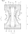
Fig. 2] Fig. 2 is a schematic plan of the skin facing surface side (interior surface side) of the diaper shown inFig. 1 in its flat-out, uncontracted configuration. - [
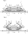
Fig. 3] Fig. 3 is a schematic cross-section taken along line III-III ofFig. 2 . - [
Fig. 4] Fig. 4 is a schematic cross-section of the crotch portion of the diaper shown inFig. 1 in a worn state (corresponding toFig. 3 ). - [
Fig. 5] Fig. 5 is an enlarged plan view schematically illustrating the surface of the lower joined region of a leak-proof cuff. - [
Fig. 6] Fig. 6 is an enlarged plan view schematically illustrating the surface of the upper soft region of a leak-proof cuff. - [
Fig. 7] Fig. 7 is an enlarged schematic cross-section of a leak-proof cuff. - When the soft nonwoven fabric disclosed in
patent literatures 1 through 3 is used to make leak-proof cuffs with the view to improving the feel to the touch of leak-proof cuffs, the resulting leak-proof cuff tends to have insufficient upstanding capabilities due to the low stiffness of the nonwoven fabric, resulting in a failure to conform to the wearer's movement during wear. As a result, the diaper has a reduced fit to the skin to allow leakage of bodily waste. - In the light of the above circumstances, the invention provides a disposable diaper of which the leak-proof cuffs are formed of soften nonwoven fabric and yet have good upstanding capabilities to provide a good fit to the wearer's skin while worn.
- The invention will be described on the basis of its preferred embodiments with reference to the accompanying drawings.
Figs. 1 and2 illustrate a disposable pull-ondiaper 1 according to an embodiment of the invention. As illustrated inFigs. 1 and2 , thediaper 1 includes a front portion F adapted to be worn about the front of a wearer, a rear portion R adapted to be worn about the back of the wearer, and a crotch portion M intermediate between the front portion F and the rear portions R. The front and rear portions F, R are connected to each other to form a tubular lower torso portion adapted to be worn about the wearer's lower torso. Thediaper 1 has a longitudinal direction X corresponding to the wearer's front-to-back direction, i.e., the direction from the front portion to the crotch portion M to the rear portion R and a lateral direction Y perpendicular to the longitudinal direction X. Thediaper 1 includes anabsorbent assembly 2 and anouter cover 3 disposed on the non-skin facing surface side of theabsorbent assembly 2. - As used herein, the term "skin facing surface" refers to the side of a disposable diaper or a member constituting the diaper (e.g., the absorbent assembly) facing the wearer's skin while worn, i.e., the surface relatively closer to the wearer's skin. The term "non-skin facing surface" refers to the side of a disposable diaper or a member constituting the diaper facing away from the wearer's skin while worn, i.e., the surface relatively farther from the wearer's skin. As used herein, the expression "while worn" and its analogues means the state of a disposable diaper maintained in an ordinarily worn state, i.e., in the right position on the body.
- The front portion F and the rear portion M of the
diaper 1 are joined together along their lateral side edges to form theouter cover 3 by a joining means, such as adhesive bonding, heat sealing, or ultrasonic sealing. Thediaper 1 is of pull-on type as illustrated inFig. 1 . Thediaper 1 has a pair of side seams S, a waist opening WH for receiving the waist of a wearer, and a pair of leg openings LH for receiving the legs of the wearer. - When the
diaper 1 in a flat-out, uncontracted configuration is sectioned into equal thirds in the longitudinal direction X, the front, rear, and crotch portion F, R, and M correspond to the thirds as can be seen fromFig. 2 . Theabsorbent assembly 2 of thediaper 1 shown inFig. 2 is generally rectangular longer in the longitudinal direction X. Theabsorbent assembly 2 straddles the front portion F and the rear portion R. As used herein, the expression "flat-out, uncontracted configuration" (of the diaper 1) means a state in which thediaper 1 is opened by cutting apart the side seams S and with every elastic member stretched out until the diaper is straightened up to its design dimension with any influences of elastic members eliminated. Theabsorbent assembly 2 is located in the lateral middle of theouter cover 3. Theabsorbent assembly 2 is joined to theouter cover 3 by a joining means, such as adhesive bonding. - The
absorbent assembly 2 is, as illustrated inFig. 2 , includes a liquid retentiveabsorbent member 4 and a liquidpermeable topsheet 5 providing the skin facing surface of thediaper 1. Theabsorbent member 4 and thetopsheet 5 are joined to each other by a known joining means, such as adhesive bonding. Theabsorbent member 4 is longer in the longitudinal direction X of thediaper 1 similarly to theabsorbent assembly 2. - As illustrated in
Figs. 2 and3 , theabsorbent member 4 includes anabsorbent core 40 and acore wrap sheet 41 covering theabsorbent core 40. Theabsorbent core 40 is formed of a fiber aggregate that may have an absorbent polymer dispersed therein. Thecore wrap sheet 41 is formed of tissue or water-permeable nonwoven fabric. Thecore wrap sheet 41 preferably covers the entire area of the skin facing surface and the non-skin facing surface of theabsorbent core 40. - The
absorbent core 40 has a multi-layer structure as illustrated inFig. 3 . In more detail, theabsorbent core 40 has a dual layer structure composed of a rectangular lowerabsorbent layer 45 and an upperabsorbent layer 46 stacked on part of the lowerabsorbent layer 45. Theabsorbent core 40 includes acentral portion 42 in the lateral middle of the crotch portion M. Thecentral portion 42 is formed by stacking the upperabsorbent layer 46 on the lowerabsorbent layer 45. Theabsorbent core 40 includes a pair ofside portions 43 laterally opposite relative to thecentral portion 42. There is no upperabsorbent layer 46 stacked on the lowerabsorbent layer 45 in theside portions 43. Therefore, thecentral portion 42 is thicker than theside portions 43. Theabsorbent core 40 may have a single layer structure. - The
absorbent core 40 may or may not have a flexure region in the inside in the lateral direction. The flexure region may be a slit formed through the thickness of theabsorbent core 40 or a low basis weight region having a lower basis weight than the surroundings. As illustrated inFigs. 2 and3 , theabsorbent core 40 of the present embodiment has a pair ofslits 44 extending in the longitudinal direction X as a flexure region. Theslits 44 are located laterally inward of the longitudinally extendingside edges 2s of theabsorbent core 40 and laterally outward of the stack of the lowerabsorbent layer 45 and the upperabsorbent layer 46 in the crotch portion M. The low basis weight region which may be provided in place of theslit 44 preferably has a basis weight of 10 to 220 g/m2, more preferably 10 to 180 g/m2. - The
topsheet 5 is disposed on the skin facing surface side of theabsorbent member 4. As illustrated inFig. 3 , thetopsheet 5 covers the entire area of the skin facing surface side of theabsorbent member 4 and wraps around both longitudinally-extending side edges to the non-skin facing surface side to cover the non-skin facing surface side of theside portions 43 of theabsorbent member 4. - The
absorbent assembly 2 is covered on its non-skin facing surface side with a liquid impermeable leak-proof sheet 7 formed of a resin film as illustrated inFig. 3 . The term "liquid impermeable" as used with respect to the leak-proof sheet 7 is intended to include "sparingly liquid permeable". The leak-proof sheet 7 is placed to cover the entire area of the non-skin facing surface of theabsorbent member 4. To the skin facing surface of theouter cover 3 are joined the leak-proof sheet 7,nonwoven fabric 60 that forms the leak-proof cuffs 6, and theabsorbent assembly 2 in the order described with an adhesive, such as a hot-melt adhesive. - The
outer cover 3 of thediaper 1 is made up of two outer cover-formingsheets Fig. 3 . As illustrated inFig. 2 , waistelastic members 33 forming waist gathers along the circumferential edge of the waist opening WH, legelastic members 34 forming leg gathers along the circumferential edge of the leg openings LH, and lower torsoelastic members 35 forming lower torso gathers in a lower torso region are arranged between the twosheets elastic members sheets - As illustrated in
Fig. 2 , theabsorbent assembly 2 has a pair of leak-proof cuffs 6 provided on its skin facing surface in the opposite, longitudinally extending lateral side portions thereof. Each leak-proof cuff 6 is formed of highly pliable nonwoven fabric in view of upstanding capabilities and flexibility to provide a good fit to the body of a wearer. The pliability of thenonwoven fabric 60 can be evaluated in terms of a compression load value. Thenonwoven fabric 60 preferably has a lateral compression load value of 5 cN or less, more preferably 4 cN or less. The closer to zero the compression load value, the better, but a compression load value of 1 cN or more will be enough for sufficient pliability. The lateral compression load value of thenonwoven fabric 60 can be measured as follows. - Method for determining compression load value:
A leak-proof cuff 6 is cut off theabsorbent assembly 2. A 20 mm wide sample having a length of 80 mm along the longitudinal direction is cut out from thenonwoven fabric 60 within a region between the opposing front and rear fixed portions 6F, 6R, at which the elasticizedfree edge region 64 having the leak-proof cuff elastic member fixed therein is fixed to thetopsheet 5. When two facing layers of the nonwoven fabric are joined to each other, they are separated apart using a solvent or whatever to prepare a single sheet. The sample is folded lengthwise in two and again folded lengthwise in two to make a 4-layered specimen. When the leak-proof cuff has a region where two layers of the nonwoven fabric are joined with a 5 mm-wide lateral edge portion thereof remaining unjoined continuously in the longitudinal direction, a sample measuring 40 mm by 20 mm may be cut out of that region and folded lengthwise in two to prepare a 4-layered specimen. In that case, the non-bonded side of the specimen is subjected to the measurement. The specimen is smoothed out, and the 4 layers of the non-joined edge portion is clamped with a bulldog clip or something with their edges aligned. - The specimen (width: 20 mm) is set with the direction Y vertical and the unjoined edge portion up and clamped by the lower jaw of a compression tester (e.g., Autograph AG-X from Shimadzu Corp.) such that the 5-mm wide upper edges project upward from the lower jaw. A 30 mm diameter circular compression plate attached above the specimen compresses the specimen at a rate of 10 mm/min to record the maximum load.
- The dimension of the specimen in the lateral direction Y may be 20 mm or less as long as it can be clamped so as to project upward by 5 mm from the lower jaw.
- Five samples are tested, and the average of the measurements is taken as the compression load value of the nonwoven fabric.
- The leak-
proof cuff 6 of the embodiment shown inFig. 3 is formed of a single sheet ofnonwoven fabric 60 folded in two layers facing each other. - The leak-
proof cuff 6 has afree edge 61 and a fixededge 62 along opposite lateral side edges. Thefree edge 61 contains one or moreelastic member 63 adhesively fixed between the facing layers of thenonwoven fabric 60. Having theelastic member 63 fixed in its stretched state along the longitudinal direction X, the leak-proof cuff 6 is provided with the elasticizedfree edge region 64 arranged along thefree edge 61. As illustrated inFig. 3 , the edge portion opposite to thefree edge 61 of the leak-proof cuff 6 is joined to the part of thetopsheet 5 that is wrapped around to the non-skin facing surface of theside portion 43 of theabsorbent member 4 to form the fixededge 62. The joining of the fixededge 62 can be achieved by a known bonding method, such as heat sealing, ultrasonic sealing, or hot-melt adhesive bonding. The fixededge 62 extends in parallel to theside edge 2s of theabsorbent assembly 2. - As illustrated in
Fig. 2 , the leak-proof cuff 6 has a fixedend portion 65 fixed to thetopsheet 5 of theabsorbent assembly 2. The fixed end portion is located at longitudinal ends of the leak-proof cuff 6. The longitudinally opposite end portions of each leak-proof cuff 6, one in the front portion F and the other in the rear portion R, that include thefree edge 61 are fixed to thetopsheet 5 to form thefixed end portions 65. The leak-proof cuff 6 is configured to upstand in the crotch portion M during wear upon contraction of theelastic members 63 fixed in their stretched state as depicted inFig. 4 . The upstanding leak-proof cuffs 6 prevent bodily waste, such as urine, from running laterally outward. - As illustrated in
Figs. 2 and3 , the leak-proof cuff 6 in a flat-out, uncontracted state has afold 66. The leak-proof cuff 6 is folded along thefold 66. Thefold 66 is located between thefree edge 61 and the fixededge 62. The part of the leak-proof cuff 6 between thefree edge 61 and thefold 66 is folded over the skin facing surface of theabsorbent assembly 2. Thefold 66 is located laterally outward of thefree edge 61. The so folded leak-proof cuff 6 is of what we call inward fold type. - The leak-
proof cuff 6 may or may not have an elastic member along thefold 66. In the embodiment shown inFig. 3 , the leak-proof cuff 6 has oneelastic member 67 along thefold 66 to help the leak-proof cuff 6 to bend easily. Theelastic member 67 is adhesively fixed in its stretched state along the longitudinal direction X between the two layers of thenonwoven fabric 60. - As illustrated in
Fig. 3 , the leak-proof cuff 6 includes a lower joinedregion 68 between thefold 66 and the fixededge 62 where the two layers of thenonwoven fabric 60 are partially or entirely joined to each other. The lower joinedregion 68 extends in the longitudinal direction X from the front portion F to the rear portion R. - As illustrated in
Fig. 3 , the leak-proof cuff 6 includes an uppersoft region 69 formed of the two layers of thenonwoven fabric 60 and located between the elasticizedfree edge region 64 and thefold 66. Specifically, the uppersoft region 69 is located between the laterally proximal edge of the elasticizedfree edge region 64 and thefold 66. When the proximal edge of the elasticizedfree edge region 64 is indistinct, the region between theelastic member 63 of the elasticizedfree edge region 64 and thefold 66 is defined to be the uppersoft region 69. When there is a plurality ofelastic members 63 providing the elasticizedfree edge region 64, the uppersoft region 69 is a region between the most laterally proximalelastic member 63 and thefold 66. The uppersoft region 69 extends in the longitudinal direction X between the front portion F and the rear portion R. - The
diaper 1 of the present embodiment has a pleasant feel to the skin since the region between the elasticizedfree edge region 64 and the fixededge 62 is formed of thesoft nonwoven fabric 60 having a compression load value of as low as 5 cN or less. As illustrated inFigs. 3 and 4 , the leak-proof cuff 6 has a lower joinedregion 68 formed of two layers of thenonwoven fabric 60 joined to each other. The lower joinedregion 68 thus provides the lower portion of the leak-proof cuff 6 from thefold 66 to the fixededge 62 with stiffness. As a result, while the leak-proof cuff 6 is formed of thesoft nonwoven fabric 60, it exhibits good upstanding capabilities. - The two layers of the
nonwoven fabric 60 in the lower joinedregion 68 are fusion bonded in parts to form fusion bonds, whereby the leak-proof cuff 6 has improved resistance to water pressure to provide effective protection against leakage. - As illustrated in
Figs. 3 and 4 , the leak-proof cuff 6 has the uppersoft region 69 between the elasticizedfree edge region 64 and thefold 66. The uppersoft region 69 is formed of two layers of thenonwoven fabric 60 remaining unjoined to each other or joined together with a lower peel strength than the two layers of thenonwoven fabric 60 of the lower joinedregion 69. The uppersoft region 69 thus maintains the essential pliability of thesoft nonwoven fabric 60. Therefore, the leak-proof cuff 6 provides a better fit to the skin owing to the uppersoft region 69 conforming to the skin's movement in contact with the skin during wear. As such, thediaper 1 of the embodiment having the leak-proof cuff 6 including the lower joinedregion 68 and the uppersoft region 69 provides a superior fit to the wearer's skin, with the leak-proof cuff 6 satisfying the conflicting requirements of soft feel to the touch and good upstanding capabilities. - To ensure the effect of the lower joined
region 68 in providing good upstanding capabilities of the leak-proof cuff 6, the peel strength between the two layers of thenonwoven fabric 60 in the lower joinedregion 68 is preferably 1.0 N/30 mm or higher, more preferably 1.2 N/30 mm or higher, preferably 3.0 N/30 mm or lower, more preferably 2.8 N/30 mm or lower, specifically preferably 1.0 to 3.0 N/30 mm, more preferably 1.2 to 2.8 N/30 mm. - To ensure the conformability of the upper
soft region 69 to the skin's movement in contact with the skin, the peel strength between the two layers of thenonwoven fabric 60 in the uppersoft region 69 is preferably lower than 1.0 N/30 mm, more preferably 0.5 N/30 mm or lower. It is even more preferred for the two nonwoven layers to be unjoined. The closer to 0 N/30 mm the peel strength of the uppersoft region 69, the better, but a peel strength of 0.1 N/30 mm or higher will be sufficiently low to show sufficient conformability to the skin. - The peel strength of the lower joined
region 68 and the uppersoft region 69 is measured by the method below. - A rectangular specimen measuring longer than 50 mm in the longitudinal direction X and 30 mm in the lateral direction Y is cut out from each of the lower joined
region 68 and the uppersoft region 69 of the leak-proof cuff 6 of an unused disposable diaper. The two layers of thenonwoven fabric 60 are peeled apart from one of the longitudinal ends, and the separated nonwoven layers are clamped in the jaws of a tensile tester (e.g., Tensilon RTC series, from A and D Co., Ltd.) in a T-configuration at an initial jaw separation of 50 mm. The jaws are further separated at a rate of 300 mm/min to record the maximum strength. The measurement is taken in triplicate, and the average maximum strength is defined to be an interlaminar peel strength in unit of N/30 mm. - To further improve the upstanding capabilities of the leak-
proof cuff 6 by taking advantage of the stiffness of theabsorbent member 4, it is preferred for the fixededge 62 of the leak-proof cuff 6 be located laterally inward of theside edge 2s of theabsorbent assembly 2 as illustrated inFig. 3 . - To make the
side portions 43 of theabsorbent member 4 bend upward during wear so as to prevent bodily waste from running laterally outward, it is preferred that an entire of or a part of the lower joinedregion 68 be located laterally inward of theside edge 2s of theabsorbent assembly 2 as illustrated inFig. 4 . - The
absorbent core 40 of thediaper 1 has theslits 44. In the diaper of that type, the fixededge 62 of the leak-proof cuff 6 is preferably located substantially directly beneath theslit 44 as illustrated inFig. 4 so as to ensure theside portions 43 of theabsorbent member 4 bending upward. - Among the upper
soft region 69 and the lower joinedregion 68 of the leak-proof cuff 6, at least the lower joinedregion 68 preferably hasfusion bonds 88 resulting from fusion bonding the two layers of thenonwoven fabric 60 in parts to impart stiffness to the lower portion of the leak-proof cuff 6 thereby to ensure good upstanding of the leak-proof cuff 6 as illustrated inFigs. 4 and5 . - It is preferred, from the viewpoint of helping the upper
soft region 69 to smoothly move with the wearer's movement during wear, for the two layers of thenonwoven fabric 60 of the uppersoft region 69 to remain unjoined to each other. The two layers of thenonwoven fabric 60 of the uppersoft region 69 may be fusion bonded in parts to formfusion bonds 89 as illustrated inFigs. 4 and6 so that the two nonwoven layers of thenonwoven fabric 60 may not be spaced from each other when the leak-proof cuff 6 is made to upstand by the contraction of theelastic member 63. As a result of the formation of thefusion bonds 89, the leak-proof cuff 6 is given moderate stiffness and thereby prevented from turning outboard, which will provide benefits for a caregiver in putting on the diaper. - To provide a pleasant feel to the skin, the
nonwoven fabric 60 forming the leak-proof cuff 6 preferably has a mean deviation of coefficient of friction (MMD) of 0.015 or smaller. For the same purpose, the MMD of thenonwoven fabric 60 is more preferably 0.012 or smaller, even more preferably 0.010 or smaller. The closer to zero the MMD, the better, but an MMD of 0.003 or higher will be sufficiently small to ensure a sufficiently good feel to the skin. - To provide a good feel to the skin, the
nonwoven fabric 60 forming the leak-proof cuff 6 preferably has a mean deviation of surface roughness (SMD) of 2.2 µm or smaller, more preferably 2.0 µm or smaller. The closer to zero the SMD, the better, but an SMD of 0.5 µm or higher will be sufficiently small to ensure a sufficiently good feel to the skin. - The MMD and SMD can be determined as follows using KESFB4-AUTO-A (trade name) from Kato Tech Co., Ltd. in accordance with the method described in Kawabata, Hideo, fuai hyouka no hyoujunka to kaiseki (Standardization and Analysis of Hand Evaluation), Japanese Hand Evaluation and Standardization Committee (HESC), The Textile Machinery Soc. of Japan, 2nd Ed. (Jul. 10, 1980).
- Method for determining mean deviation of friction coefficient (MMD):
A sample measuring 20 cm by 20 cm is cut out of the nonwoven fabric forming the leak-proof cuff. When the nonwoven fabric being tested is short of that size, the size of the sample may be altered appropriately. The sample is clamped on a flat metal plate surface. A contact sensor is pressed onto the sample at a contact force of 49 cN, and the sample is moved horizontally at a constant speed of 0.1 cm/sec by 2 cm to be given a uniaxial tension of 7.3 cN/cm. The contact sensor is the same as one used for measuring the surface roughness, and is composed of a set of 20 piano wires of 0.5 mm in diameter arranged in parallel and U-shaped with a base width of 10 mm. The contact sensor is pressed onto the sample at a contact force of 49 cN using a weight. The mean deviation of friction coefficient is represented in terms of MMD value. The measurement is taken in both the MD and CD to obtain MMDMD and MMDCD, respectively, an average of which obtained by the following formula (2) is taken as a mean deviation of friction coefficient MMD. In the case where the nonwoven fabric sheet is too small to make specimens for MD and CD measurements, either MMDMD or MMDCD is adopted. MD means the machine direction in the production of the nonwoven fabric or the longitudinal direction of the diaper, and CD means a direction perpendicular to the MD.
- Method for determining surface roughness mean deviation (SMD):
A sample measuring 20 cm by 20 cm is cut out of the nonwoven fabric forming the leak-proof cuff. When the nonwoven fabric being tested is short of that size, the size of the sample may be altered appropriately. The sample is clamped on a flat metal plate surface. A contact sensor is pressed onto the sample at a contact force of 9.8 cN (with an uncertainty of ±0.49 cN), and the sample is moved horizontally at a constant speed of 0.1 cm/sec by 2 cm to be given a uniaxial tension of 7.3 cN/cm. The contact sensor is composed of a U-shaped single piano wire of 0.5 mm in diameter and 5 mm at the base. The contact sensor is urged onto the sample by a spring at a contact force of 9.8 cN. The spring had a spring constant of 24.5 cN/mm (with an uncertainty of ±0.98 cN/mm) and a resonant frequency of at least 30 Hz out of contact with the sample surface. The mean deviation of surface roughness is represented in terms of SMD value. The measurement is taken in both the MD and CD to obtain SMDMD and SMDCD, respectively, an average of which obtained by the following formula (1) is taken as a mean deviation of surface roughness SMD In the case where the nonwoven fabric sheet is too small to make specimens for MD and CD measurements, either SMDMD or SMDCD is adopted. The MD and CD are as defined above.
- Each leak-
proof cuff 6 is formed of two facing layers of thenonwoven fabric 60 having an MMD of 0.015 or less. The facing nonwoven layers may be formed of different types of nonwoven fabrics that meet the MMD requirement or of a single sheet of nonwoven fabric that meets the MMD requirement folded in two. - With a view to imparting to the leak-
proof cuff 6 cushioning properties created by surface unevenness, thenonwoven fabric 60 may preferably have embosses 80, where the constituent fibers are united, theembosses 80 being formed by embossing in a discrete pattern in plan view as shown inFigs. 5 and 6 . In view of improved feel to the touch, thenonwoven fabric 60 preferably contains as a main component of constituent fibers a propylene random copolymer composed of propylene and an α-olefin other than propylene. Examples of suitable nonwoven fabrics include spun-bonded, melt-blown, and spun-bonded/melt-blown laminated nonwoven fabric. With a view to improving the feel to the skin, the nonwoven fabric may contain a softening agent, such as a surfactant. - Referring to
Fig. 7 , each of the two facing layers of thenonwoven fabric 60 has a facingsurface 6f that faces the opposing layer and anon-facing surface 6n on the opposite side, and each emboss 80 has a larger depth on the facingsurface 6f than on thenon-facing surface 6n with the view of improving the feel of the leak-proof cuff 6 to the touch. As illustrated inFig. 7 , the individual embosses 80 of each nonwoven layer have adepression 91 on the facingsurface 6f and adepression 92 on thenon-facing surface 6n, and thedepression 91 is preferably deeper than thedepression 92. The term "depression - Method for measuring depth of depression of emboss 80:
Thenonwoven fabric 60 is cut using a knife, cutter, razor, and so on in the thickness direction along a line passing through aemboss 80, taking care not to deform the cut surface of theemboss 80. The cut surface is observed to measure the thicknesses of theemboss 80 and the adjacent, non-depressed portion on either side, and the difference in thickness is defined to be the depth of theemboss 80. The measurement may be made using, for example, Microscope VHX-1000 from Keyence Corp. fitted with a middle-range zoom lens at a tilt angle of 90°. The measurement is taken at ten embosses 80, and the average of the results is taken as the depth of theembosses 80. - The fusion bonds 88 and 89 can be formed by heat embossing, high-frequency sealing, ultrasonic sealing, and the like. Heat embossing is recommended for forming fusion bonds with a smaller thickness and a better feel against the skin. To improve the feel of the leak-
proof cuff 6, as illustrated inFig. 7 , thefusion bonds depression 93 on thenonwoven layer 60a facing the absorbent assembly and adepression 94 on the othernonwoven layer 60b such that thedepression 93 is deeper than thedepression 94.Such depressions nonwoven layer 60a. From the viewpoint of the balance between ease of processing and peel strength, theindividual fusion bonds 88 preferably have a rectangular shape extending in the longitudinal direction X or, as illustrated inFig. 5 , an elongated circular shape extending in the longitudinal direction X, or a like shape. - With a view to preventing bodily waste from striking through the leak-
proof cuff 6, thenonwoven fabric 60 preferably has a water pressure resistance of 130 mm or higher, more preferably 150 mm or higher. The higher the water pressure resistance, the better, but an upper limit of the water pressure resistance would be 250 mm for the leak-proof cuff 6 to exhibit sufficient protection against leakage. The water pressure resistance is represented in terms of water level (mm) in a water pressure resistance test. The water pressure resistance is measured by a water pressure resistance test in accordance with JIS L1092 (hydrostatic pressure method, method B). - From the standpoint of softness and breathability of the leak-
proof cuff 6, in thenonwoven fabric 60, the ratio of the total area of theembosses 80 to the surface area of one surface of thenonwoven fabric 60 is preferably 16% or less, more preferably 12% or less. The lower the total area ratio, the better, but a lower limit of the total area of theembosses 80 would be 5% or higher for obtaining sufficient softness and breathability. - From the standpoint of softness and breathability of the leak-
proof cuff 6, in the leak-proof cuff 6, the ratio of the total area of thefusion bonds 89 to the surface area of the uppersoft region 69 is preferably 5% or less, more preferably 4% or less. The lower the total area ratio, the better, but a lower limit of the ratio of the total area of thefusion bonds 89 would be 2% or higher for obtaining sufficient softness and breathability. - To obtain both upstanding capabilities and breathability of the leak-
proof cuff 6, in the leak-proof cuff 6, the ratio of the total area of thefusion bonds 88 to the surface area of the lower joinedregion 68 is preferably higher than the above-described total area ratio of the fusion bonds 89. The total area ratio of thefusion bonds 88 is preferably 5% or less, more preferably 4.5% or less. The lower the total area ratio, the preferred, but a lower limit of the total area ratio of thefusion bonds 88 would be 2.5% or higher for obtaining sufficient upstanding capabilities and breathability. - The area of the
individual fusion bonds fusion bonds nonwoven fabric 60 can be formed at locations other than theembosses 80 to secure sufficient peel strength between the nonwoven layers. In order for the lower joinedregion 68 to provide the leak-proof cuff 6 with upstanding capabilities and for the uppersoft region 69 to provide the leak-proof cuff 6 with a soft feel, theindividual fusion bonds 88 preferably have a larger area than the individual fusion bonds 89. - The area of the individual embosses 80 formed in the
nonwoven fabric 60 is preferably 0.10 mm2 or larger, more preferably 0.13 mm2 or large, preferably 0.35 mm2 or smaller, more preferably 0.32 mm2 or smaller. - The area of the
individual fusion bonds 88 formed in the lower joinedregion 68 is preferably 0.38 mm2 or larger, more preferably 0.4 mm2 or larger, preferably 3.0 mm2 or smaller, more preferably 2.7 mm2 or smaller. - The area of the
individual fusion bonds 89 formed in the uppersoft region 69 is preferably 0.35 mm2 or larger, more preferably 0.38 mm2 or larger, preferably 2 mm2 or smaller, more preferably 1.7 mm2 or smaller. - The areas of the
embosses 80,fusion bonds 88, andfusion bonds 89 can be measured as follows. - Method for measuring areas of
embosses 80 andfusion bonds 88, 89:
A leak-proof cuff 6 is cut off from thediaper 1, and a 10 mm by 10 mm piece containing thefusion bonds soft region 69 or the lower joinedregion 68, respectively. The cut piece is subjected to image analysis using, e.g., VHX-1000 from Keyence to measure the area of every fusion bond except those with part cut off. The average of all the measurements is taken as the area of the individual fusion bonds. The area of the individual embosses 80 is measured in the same manner. That is, a 10 mm by 10 mm piece is cut out from the embossed region having theembosses 80 of thenonwoven fabric 60 forming the leak-proof cuff 6. The cut piece is analyzed using an image analyzer to measure the area of the individual embosses 80. - The ratio of the total area of the
fusion bonds 89 to the surface area of the uppersoft region 69 and the ratio of the total area of thefusion bonds 88 to the surface area of the lower joinedregion 68 are calculated in terms of the total area of the fusion bonds per unit area (10 mm by 10 mm = 100 mm2) of the cut piece. The measurement is taken on at least three cut pieces, and the average of the measurement results is taken as the ratio of the total area of the fusion bonds to the area of the lower joined region. In the determination of the total fusion bond area ratios, the area measurement is taken of all the fusion bonds inclusive of those with part cut off. Similarly, the ratio of the total area of theembosses 80 to the surface area of one surface of thenonwoven fabric 60 is obtained in terms of the total area of theembosses 80 per unit area (10 mm by 10 mm = 100 mm2) of the cut piece. At least three cut pieces are prepared, and the average of the measurements is taken as the ratio of the total area of theembosses 80 to the surface area of one side of thenonwoven fabric 60. - To obtain both upstanding capabilities and breathability of the leak-
proof cuff 6, the shortest distance between the closest twofusion bonds 88 is preferably longer than the shortest distance between the closest two embosses 80. For the same purpose, the shortest distance between the closest twofusion bonds 89 is preferably longer than the shortest distance between the closest two embosses 80. - The shortest distance between the two
closest embosses 80 of thenonwoven fabric 60 is preferably 0.4 mm or longer, more preferably 0.5 mm or longer, preferably 5 mm or shorter, more preferably 4.5 mm or shorter. - The shortest distance between the two
closest fusion bonds 88 of the lower joinedregion 68 is preferably 3 mm or longer, more preferably 3.1 mm or longer, preferably 10 mm or shorter, more preferably 9.5 mm or shorter. - The shortest distance between the two
closest fusion bonds 89 of the uppersoft region 69 is preferably 3 mm or longer, more preferably 3.1 mm or longer, preferably 16 mm or shorter, more preferably 15 mm or shorter. - Materials making up constituent members of the
diaper 1 are not particularly limited and can be selected from those commonly used in the art. For example, thetopsheet 5 may be formed of various types of nonwoven fabric or perforated film. The leak-proof sheet 7 may be formed of sparingly liquid-permeable resin film or spun-bonded/melt-blown/spun-bonded laminated nonwoven fabric. The elastic members may be rubber treads. The outer cover-formingsheets - The invention has been described on the basis of its preferred embodiments, but it should be understood that the invention is not deemed to be limited thereto, and various changes and modifications can be made therein. For example, while the disposable pull-on
diaper 1 according to the embodiment ofFig. 1 is of the type in which theouter cover 3 is continuous from the front portion F to the crotch portion M to the rear portion R, the disposable diaper of the invention may be of the type in which the outer cover is divided into a front panel adapted to be worn about the wearer's front and a rear panel adapted to be worn about the wearer's back, the front panel and the rear panel are connected along a pair of side seams to form a tubular shape, and the absorbent assembly is attached to the outer cover so as to bridge the front and the rear panel. The disposable diaper of the invention may be of an open-style, taped type. - The leak-
proof cuff 6 of inward fold type as used in the diaper 1 (Fig. 3 ) may be replaced with a leak-proof cuff of outward fold type. An outward fold type leak-proof cuff has the fixededge 62 located laterally outward of the longitudinally extending side edge of theabsorbent member 4, thefold 66 located on theabsorbent assembly 2, and thefree edge 61 located laterally outward of thefold 66. - The following clauses are considered further descriptive of the disclosed embodiments of the invention.
-
- 1. A disposable diaper comprising an absorbent assembly comprising: a liquid permeable topsheet and an absorbent member; and a leak-proof cuff disposed along each of the sides of the absorbent assembly,
- the disposable diaper having a longitudinal direction, and a lateral direction perpendicular to the longitudinal direction,
- the absorbent assembly having laterally opposite, longitudinally extending sides and side edges,
- the leak-proof cuff having opposite lateral side edges and opposite longitudinal ends, comprising two facing nonwoven layers of nonwoven fabric, and having a free edge along one of the lateral side edges and a fixed edge along the other side edge,
- the leak-proof cuff comprising:
- a fixed end portion fixed to the absorbent assembly and located at the longitudinal ends of the leak-proof cuff,
- an elasticized free edge region having an elastic member arranged along the free edge, and
- a fold located between the free edge and the fixed edge,
- the nonwoven fabric having an area located between the fixed edge and the elasticized free edge region, the area having a lateral compression load value of 5 cN or less and
- the leak-proof cuff comprising:
- an upper soft region comprising the two nonwoven layers and being located between the elasticized free edge region and the fold; and
- a lower joined region comprising the two nonwoven layers joined together partially or entirely and being located between the fold and the fixed edge,
- the two nonwoven layers of the upper soft region being unjoined together or having a lower peel strength than the two nonwoven layers of the lower joined region.
- 2. The disposable diaper according to
clause 1, wherein the leak-proof cuff includes an elastic member in the fold. - 3. The disposable diaper according to
clause - 4. The disposable diaper according to any one of
clauses 1 to 3, wherein the fixed edge of the leak-proof cuff is located laterally inward of the longitudinally extending side edge of the absorbent assembly, and an entire of or a part of the lower joined region is located laterally inward of the side edge of the absorbent assembly. - 5. The disposable diaper according to any one of
clauses 1 to 4, wherein the absorbent member has a longitudinally extending slit or low basis weight region laterally inward of the side edge of the absorbent assembly. - 6. The disposable diaper according to any one of
clauses 1 to 5, wherein among the lower joined region and the upper soft region, at least the lower joined region has fusion bonds formed by fusion bonding the two nonwoven layers in parts. - 7. The disposable diaper according to any one of
clauses 1 to 5, wherein at least the lower joined region of the upper soft region and the lower joined region has fusion bonds formed by fusion bonding the two nonwoven layers in parts. - 8. The disposable diaper according to
clause 7, wherein the fusion bonds of the lower joined region have a larger area than the fusion bonds of the upper soft region. - 9. The disposable diaper according to
clause 7 or 8, wherein the individual fusion bonds of the upper soft region have an average area of 2 mm2 or smaller. - 10. The disposable diaper according to any one of
clauses 7 to 9, wherein the upper soft region has a peel strength of 0.5 N/30 mm or less between the two nonwoven layers. - 11. The disposable diaper according to any one of
clauses 6 to 10, wherein the two nonwoven layers have embosses where the constituent fibers are united by embossing in a discrete pattern in plan view, and the fusion bonds have a larger area than the embosses. - 12. The disposable diaper according to clause 11, wherein the embosses are deeper on the mutually facing sides of the two nonwoven layers than on the other sides.
- 13. The disposable diaper according to clause 11 or 12, wherein the ratio of the total area of the embosses to the surface area of one surface of the nonwoven layer is 16% or less.
- 14. The disposable diaper according to any one of clauses 11 to 13, wherein the ratio of the total area of the embosses to the surface area of one surface of the nonwoven layer is 12% or less.
- 15. The disposable diaper according to any one of clauses 11 to 14, wherein the shortest distance between the closest two fusion bonds is longer than the shortest distance between the closest two embosses.
- 16. The disposable diaper according to clause 15, wherein the shortest distance between the closest two fusion bonds is 3 mm or longer.
- 17. The disposable diaper according to any one of
clauses 6 to 16, wherein the fusion bonds are formed by heat embossing and each provide a deeper depression on the nonwoven layer facing the absorbent assembly than on the other nonwoven layer. - 18. The disposable diaper according to any one of
clauses 6 to 17, wherein a ratio of a total area of the fusion bonds of the lower joined region to the surface area of the lower joined region is 5% or less. - 19. The disposable diaper according to any one of
clauses 6 to 18, wherein the fusion bonds of at least the lower joined region have an elongated shape extending in the longitudinal direction of the diaper. - 20. The disposable diaper according to any one of
clauses 1 to 19, wherein the leak-proof cuff is formed by folding a single sheet in two - 21. The disposable diaper according to any one of
clauses 1 to 20, wherein the two nonwoven layers contain a propylene random copolymer as a main component of the constituent fibers. - 22. The disposable diaper according to any one of
clauses 1 to 21, wherein the two nonwoven layers have a mean deviation of coefficient of friction (MMD) of 0.012 or smaller. - 23. The disposable diaper according to any one of
clauses 1 to 22, wherein the two nonwoven layers have a mean deviation of surface roughness (SMD) of 2.2 µm or smaller. - 24. The disposable diaper according to any one of
clauses 1 to 23, wherein the two nonwoven layers contain a softening agent. - 25. The disposable diaper according to any one of
clauses 1 to 24, wherein the two nonwoven layers have a water pressure resistance of 130 mm or higher. - The leak-proof cuff of the disposable diaper of the invention feels soft to the touch and yet has good upstanding capabilities to provide a good fit to the wearer's skin.
Claims (25)
- A disposable diaper comprising an absorbent assembly comprising: a liquid permeable topsheet and an absorbent member; and a leak-proof cuff disposed along each of the sides of the absorbent assembly,the disposable diaper having a longitudinal direction, and a lateral direction perpendicular to the longitudinal direction,the absorbent assembly having laterally opposite, longitudinally extending sides and side edges,the leak-proof cuff having opposite lateral side edges and opposite longitudinal ends, comprising two facing nonwoven layers of nonwoven fabric, and having a free edge along one of the lateral side edges and a fixed edge along the other side edge,the leak-proof cuff comprising:a fixed end portion fixed to the absorbent assembly and located at the longitudinal ends of the leak-proof cuff;an elasticized free edge region having an elastic member arranged along the free edge; anda fold located between the free edge and the fixed edge,the nonwoven fabric having an area located between the fixed edge and the elasticized free edge region, the area having a lateral compression load value of 5 cN or less, andthe leak-proof cuff comprising:an upper soft region comprising the two nonwoven layers and being located between the elasticized free edge region and the fold; anda lower joined region comprising the two nonwoven layers joined together partially or entirely and being located between the fold and the fixed edge,the two nonwoven layers of the upper soft region being unjoined together or having a lower peel strength than the two nonwoven layers of the lower joined region.
- The disposable diaper according to claim 1, wherein the leak-proof cuff further comprises an elastic member in the fold.
- The disposable diaper according to claim 1 or 2, wherein the peel strength between the two nonwoven layers of the lower joined region is 1.0 N/30 mm or more, and
the two nonwoven layers of the upper soft region are unjoined together or have a peel strength of less than 1.0 N/30 mm. - The disposable diaper according to any one of claims 1 to 3, wherein the fixed edge of the leak-proof cuff is located laterally inward of the side edge of the absorbent assembly, and an entire of or a part of the lower joined region is located laterally inward of the side edge of the absorbent assembly.
- The disposable diaper according to any one of claims 1 to 4, wherein the absorbent member has a longitudinally extending slit or low basis weight region laterally inward of the side edge of the absorbent assembly.
- The disposable diaper according to any one of claims 1 to 5, wherein among the lower joined region and the upper soft region, at least the lower joined region has fusion bonds formed by fusion bonding the two nonwoven layers in parts.
- The disposable diaper according to any one of claims 1 to 5, wherein both the lower joined region and the upper soft region have fusion bonds formed by fusion bonding the two nonwoven layers in parts.
- The disposable diaper according to claim 7, wherein the fusion bonds of the lower joined region have a larger area than the fusion bonds of the upper soft region.
- The disposable diaper according to claim 7 or 8, wherein the individual fusion bonds of the upper soft region have an average area of 2 mm2 or smaller.
- The disposable diaper according to any one of claims 7 to 9, wherein the upper soft region has a peel strength of 0.5 N/30 mm or less between the two nonwoven layers.
- The disposable diaper according to any one of claims 6 to 10, wherein the two nonwoven layers each have embosses where constituent fibers are united by embossing in a discrete pattern in plan view, and the fusion bonds have a larger area than the embosses.
- The disposable diaper according to claim 11, wherein the two facing nonwoven layers have mutually facing surfaces and the other surfaces, and the embosses are deeper on the mutually facing surfaces than on the other surfaces.
- The disposable diaper according to claim 11 or 12, wherein a ratio of a total area of the embosses to the surface area of one surface of the nonwoven layer is 16% or less.
- The disposable diaper according to any one of claims 11 to 13, wherein a ratio of a total area of the embosses to the surface area of one surface of the nonwoven layer is 12% or less.
- The disposable diaper according to any one of claims 11 to 14, wherein the shortest distance between the closest two fusion bonds is longer than the shortest distance between the closest two embosses.
- The disposable diaper according to claim 15, wherein the shortest distance between the closest two fusion bonds is 3 mm or longer.
- The disposable diaper according to any one of claims 6 to 16, wherein the fusion bonds are formed by heat embossing and each provide a deeper depression on the nonwoven layer facing the absorbent assembly than on the other nonwoven layer.
- The disposable diaper according to any one of claims 6 to 17, wherein a ratio of a total area of the fusion bonds of the lower joined region to the surface area of the lower joined region is 5% or less.
- The disposable diaper according to any one of claims 6 to 18, wherein the fusion bonds of at least the lower joined region have an elongated shape extending in the longitudinal direction.
- The disposable diaper according to any one of claims 1 to 19, wherein the leak-proof cuff is formed by folding a single nonwoven fabric in two.
- The disposable diaper according to any one of claims 1 to 20, wherein the two nonwoven layers contain a propylene random copolymer as a main component of the constituent fibers.
- The disposable diaper according to any one of claims 1 to 21, wherein the two nonwoven layers have a mean deviation of coefficient of friction (MMD) of 0.012 or smaller.
- The disposable diaper according to any one of claims 1 to 22, wherein the two nonwoven layers have a mean deviation of surface roughness (SMD) of 2.2 µm or smaller.
- The disposable diaper according to any one of claims 1 to 23, wherein the two nonwoven layers contain a softening agent.
- The disposable diaper according to any one of claims 1 to 24, wherein the two nonwoven layers have a water pressure resistance of 130 mm or higher.
Applications Claiming Priority (2)
| Application Number | Priority Date | Filing Date | Title |
|---|---|---|---|
| JP2019102943A JP7212583B2 (en) | 2019-05-31 | 2019-05-31 | disposable diaper |
| PCT/JP2020/020514 WO2020241559A1 (en) | 2019-05-31 | 2020-05-25 | Disposable diaper |
Publications (3)
| Publication Number | Publication Date |
|---|---|
| EP3949923A1 true EP3949923A1 (en) | 2022-02-09 |
| EP3949923A4 EP3949923A4 (en) | 2023-01-04 |
| EP3949923B1 EP3949923B1 (en) | 2025-12-17 |
Family
ID=73552745
Family Applications (1)
| Application Number | Title | Priority Date | Filing Date |
|---|---|---|---|
| EP20814691.0A Active EP3949923B1 (en) | 2019-05-31 | 2020-05-25 | Disposable diaper |
Country Status (5)
| Country | Link |
|---|---|
| EP (1) | EP3949923B1 (en) |
| JP (1) | JP7212583B2 (en) |
| CN (1) | CN113939261B (en) |
| TW (1) | TW202110409A (en) |
| WO (1) | WO2020241559A1 (en) |
Families Citing this family (3)
| Publication number | Priority date | Publication date | Assignee | Title |
|---|---|---|---|---|
| JP2023064045A (en) * | 2021-10-25 | 2023-05-10 | 王子ホールディングス株式会社 | absorbent article |
| CN116019637A (en) * | 2021-10-25 | 2023-04-28 | 王子控股株式会社 | absorbent article |
| JP7826901B2 (en) * | 2022-01-28 | 2026-03-10 | 王子ホールディングス株式会社 | absorbent articles |
Family Cites Families (17)
| Publication number | Priority date | Publication date | Assignee | Title |
|---|---|---|---|---|
| US5558660A (en) * | 1994-09-08 | 1996-09-24 | The Procter & Gamble Company | Absorbent article having a pocket cuff with a gluteal groove spacer |
| JP3398047B2 (en) * | 1998-04-24 | 2003-04-21 | ユニ・チャーム株式会社 | Disposable pants-type diapers |
| JP3550063B2 (en) * | 1999-11-30 | 2004-08-04 | ユニ・チャーム株式会社 | Disposable diapers |
| AU2379000A (en) | 1999-12-22 | 2001-07-03 | Procter & Gamble Company, The | Disposable garment comprising meltblown nonwoven backsheet |
| JP2003265529A (en) | 2002-03-15 | 2003-09-24 | Daio Paper Corp | Disposable paper diaper |
| US20050113790A1 (en) * | 2003-11-21 | 2005-05-26 | Minako Suzuki | Absorbent article with elasticized barrier cuffs |
| KR101255592B1 (en) * | 2005-05-09 | 2013-04-16 | 가오 가부시키가이샤 | Disposable diapers |
| JP5466328B1 (en) * | 2013-09-10 | 2014-04-09 | ユニ・チャーム株式会社 | Absorbent articles |
| JP6674205B2 (en) * | 2014-10-20 | 2020-04-01 | 花王株式会社 | Pants-type disposable diapers |
| CN204352029U (en) * | 2014-12-10 | 2015-05-27 | 重庆百亚卫生用品有限公司 | Baby paper diaper |
| JP6442263B2 (en) | 2014-12-15 | 2018-12-19 | 花王株式会社 | Disposable diapers |
| JP5960791B2 (en) * | 2014-12-24 | 2016-08-02 | 花王株式会社 | Pants-type absorbent article |
| JP6180605B2 (en) * | 2015-11-20 | 2017-08-16 | 花王株式会社 | Pants-type disposable diaper |
| CN105640710B (en) * | 2016-01-06 | 2019-06-18 | 湖南康程护理用品有限公司 | A kind of absorbent article processing method of front and back leak-proof |
| CN106109100A (en) * | 2016-07-15 | 2016-11-16 | 杭州嘉杰实业有限公司 | A kind of high flexibility pants for infants and processing technology thereof |
| JP6301422B2 (en) | 2016-09-29 | 2018-03-28 | 大王製紙株式会社 | Absorbent articles |
| JP2019010348A (en) | 2017-06-30 | 2019-01-24 | 日本製紙クレシア株式会社 | Absorbent article |
-
2019
- 2019-05-31 JP JP2019102943A patent/JP7212583B2/en active Active
-
2020
- 2020-05-25 CN CN202080039415.3A patent/CN113939261B/en active Active
- 2020-05-25 WO PCT/JP2020/020514 patent/WO2020241559A1/en not_active Ceased
- 2020-05-25 TW TW109117306A patent/TW202110409A/en unknown
- 2020-05-25 EP EP20814691.0A patent/EP3949923B1/en active Active
Also Published As
| Publication number | Publication date |
|---|---|
| EP3949923B1 (en) | 2025-12-17 |
| CN113939261B (en) | 2023-02-24 |
| CN113939261A (en) | 2022-01-14 |
| JP7212583B2 (en) | 2023-01-25 |
| JP2020195507A (en) | 2020-12-10 |
| TW202110409A (en) | 2021-03-16 |
| EP3949923A4 (en) | 2023-01-04 |
| WO2020241559A1 (en) | 2020-12-03 |
Similar Documents
| Publication | Publication Date | Title |
|---|---|---|
| US9681998B2 (en) | Absorbent product with intergluteal cleft facing portion elastic member | |
| JP4342330B2 (en) | Disposable wearing items | |
| US7582348B2 (en) | Composite extensible member and method of manufacturing the same | |
| AU688372B2 (en) | Disposable menstrual panty | |
| EP3865103B1 (en) | Absorbent article | |
| EP3949923B1 (en) | Disposable diaper | |
| JP2019010348A (en) | Absorbent article | |
| WO2020110617A1 (en) | Absorbent product | |
| JP2014111222A (en) | Underpants-type disposable diaper | |
| JP4945430B2 (en) | Absorbent articles | |
| JP4526323B2 (en) | Disposable sanitary shorts | |
| KR20120113235A (en) | Disposable pants-type item of clothing | |
| EP3949922B1 (en) | Underpants-type absorbent article | |
| JP7569671B2 (en) | Disposable diapers | |
| CN111212730A (en) | Stretchable sheet for absorbent article and absorbent article using the same | |
| JP7445430B2 (en) | Absorbent article body and absorbent article | |
| JP2012050550A (en) | Underpants type disposable diaper | |
| JP3591574B2 (en) | Absorbent articles | |
| JP2014158962A (en) | Underpants type disposable diaper | |
| JP5411344B2 (en) | Absorbent articles | |
| RU2774354C1 (en) | Pants type absorbent product | |
| JP5165426B2 (en) | Absorbent articles | |
| JP2005168725A (en) | Disposable excrement treatment article | |
| EP3858315A1 (en) | Absorbent article | |
| KR900009064B1 (en) | Disposable diapers with improved fit and liquid retention |
Legal Events
| Date | Code | Title | Description |
|---|---|---|---|
| STAA | Information on the status of an ep patent application or granted ep patent |
Free format text: STATUS: THE INTERNATIONAL PUBLICATION HAS BEEN MADE |
|
| PUAI | Public reference made under article 153(3) epc to a published international application that has entered the european phase |
Free format text: ORIGINAL CODE: 0009012 |
|
| STAA | Information on the status of an ep patent application or granted ep patent |
Free format text: STATUS: REQUEST FOR EXAMINATION WAS MADE |
|
| 17P | Request for examination filed |
Effective date: 20211104 |
|
| AK | Designated contracting states |
Kind code of ref document: A1 Designated state(s): AL AT BE BG CH CY CZ DE DK EE ES FI FR GB GR HR HU IE IS IT LI LT LU LV MC MK MT NL NO PL PT RO RS SE SI SK SM TR |
|
| DAV | Request for validation of the european patent (deleted) | ||
| DAX | Request for extension of the european patent (deleted) | ||
| REG | Reference to a national code |
Ref country code: DE Ref legal event code: R079 Free format text: PREVIOUS MAIN CLASS: A61F0013490000 Ipc: A61F0013494000 Ref document number: 602020064118 Country of ref document: DE |
|
| A4 | Supplementary search report drawn up and despatched |
Effective date: 20221206 |
|
| RIC1 | Information provided on ipc code assigned before grant |
Ipc: A61F 13/535 20060101ALI20221201BHEP Ipc: A61F 13/532 20060101ALI20221201BHEP Ipc: A61F 13/49 20060101ALI20221201BHEP Ipc: A61F 13/494 20060101AFI20221201BHEP |
|
| GRAP | Despatch of communication of intention to grant a patent |
Free format text: ORIGINAL CODE: EPIDOSNIGR1 |
|
| STAA | Information on the status of an ep patent application or granted ep patent |
Free format text: STATUS: GRANT OF PATENT IS INTENDED |
|
| INTG | Intention to grant announced |
Effective date: 20250722 |
|
| GRAS | Grant fee paid |
Free format text: ORIGINAL CODE: EPIDOSNIGR3 |
|
| GRAA | (expected) grant |
Free format text: ORIGINAL CODE: 0009210 |
|
| STAA | Information on the status of an ep patent application or granted ep patent |
Free format text: STATUS: THE PATENT HAS BEEN GRANTED |
|
| AK | Designated contracting states |
Kind code of ref document: B1 Designated state(s): AL AT BE BG CH CY CZ DE DK EE ES FI FR GB GR HR HU IE IS IT LI LT LU LV MC MK MT NL NO PL PT RO RS SE SI SK SM TR |
|
| REG | Reference to a national code |
Ref country code: CH Ref legal event code: F10 Free format text: ST27 STATUS EVENT CODE: U-0-0-F10-F00 (AS PROVIDED BY THE NATIONAL OFFICE) Effective date: 20251217 Ref country code: GB Ref legal event code: FG4D |
|
| REG | Reference to a national code |
Ref country code: DE Ref legal event code: R096 Ref document number: 602020064118 Country of ref document: DE |
|
| PGFP | Annual fee paid to national office [announced via postgrant information from national office to epo] |
Ref country code: GB Payment date: 20260331 Year of fee payment: 7 |
|
| REG | Reference to a national code |
Ref country code: LT Ref legal event code: MG9D |
|
| PG25 | Lapsed in a contracting state [announced via postgrant information from national office to epo] |
Ref country code: NO Free format text: LAPSE BECAUSE OF FAILURE TO SUBMIT A TRANSLATION OF THE DESCRIPTION OR TO PAY THE FEE WITHIN THE PRESCRIBED TIME-LIMIT Effective date: 20260317 |
|
| PG25 | Lapsed in a contracting state [announced via postgrant information from national office to epo] |
Ref country code: FI Free format text: LAPSE BECAUSE OF FAILURE TO SUBMIT A TRANSLATION OF THE DESCRIPTION OR TO PAY THE FEE WITHIN THE PRESCRIBED TIME-LIMIT Effective date: 20251217 Ref country code: HR Free format text: LAPSE BECAUSE OF FAILURE TO SUBMIT A TRANSLATION OF THE DESCRIPTION OR TO PAY THE FEE WITHIN THE PRESCRIBED TIME-LIMIT Effective date: 20251217 |
|
| PG25 | Lapsed in a contracting state [announced via postgrant information from national office to epo] |
Ref country code: RS Free format text: LAPSE BECAUSE OF FAILURE TO SUBMIT A TRANSLATION OF THE DESCRIPTION OR TO PAY THE FEE WITHIN THE PRESCRIBED TIME-LIMIT Effective date: 20260317 |
|
| PG25 | Lapsed in a contracting state [announced via postgrant information from national office to epo] |
Ref country code: LV Free format text: LAPSE BECAUSE OF FAILURE TO SUBMIT A TRANSLATION OF THE DESCRIPTION OR TO PAY THE FEE WITHIN THE PRESCRIBED TIME-LIMIT Effective date: 20251217 |
|
| PG25 | Lapsed in a contracting state [announced via postgrant information from national office to epo] |
Ref country code: BG Free format text: LAPSE BECAUSE OF FAILURE TO SUBMIT A TRANSLATION OF THE DESCRIPTION OR TO PAY THE FEE WITHIN THE PRESCRIBED TIME-LIMIT Effective date: 20251217 |