EP3949906A1 - Kugelgelenkendoprothese - Google Patents
Kugelgelenkendoprothese Download PDFInfo
- Publication number
- EP3949906A1 EP3949906A1 EP21189595.8A EP21189595A EP3949906A1 EP 3949906 A1 EP3949906 A1 EP 3949906A1 EP 21189595 A EP21189595 A EP 21189595A EP 3949906 A1 EP3949906 A1 EP 3949906A1
- Authority
- EP
- European Patent Office
- Prior art keywords
- ball joint
- flattened
- articulation
- endoprosthesis
- joint head
- Prior art date
- Legal status (The legal status is an assumption and is not a legal conclusion. Google has not performed a legal analysis and makes no representation as to the accuracy of the status listed.)
- Granted
Links
Images


Classifications
-
- A—HUMAN NECESSITIES
- A61—MEDICAL OR VETERINARY SCIENCE; HYGIENE
- A61F—FILTERS IMPLANTABLE INTO BLOOD VESSELS; PROSTHESES; DEVICES PROVIDING PATENCY TO, OR PREVENTING COLLAPSING OF, TUBULAR STRUCTURES OF THE BODY, e.g. STENTS; ORTHOPAEDIC, NURSING OR CONTRACEPTIVE DEVICES; FOMENTATION; TREATMENT OR PROTECTION OF EYES OR EARS; BANDAGES, DRESSINGS OR ABSORBENT PADS; FIRST-AID KITS
- A61F2/00—Filters implantable into blood vessels; Prostheses, i.e. artificial substitutes or replacements for parts of the body; Appliances for connecting them with the body; Devices providing patency to, or preventing collapsing of, tubular structures of the body, e.g. stents
- A61F2/02—Prostheses implantable into the body
- A61F2/30—Joints
- A61F2/32—Joints for the hip
-
- A—HUMAN NECESSITIES
- A61—MEDICAL OR VETERINARY SCIENCE; HYGIENE
- A61F—FILTERS IMPLANTABLE INTO BLOOD VESSELS; PROSTHESES; DEVICES PROVIDING PATENCY TO, OR PREVENTING COLLAPSING OF, TUBULAR STRUCTURES OF THE BODY, e.g. STENTS; ORTHOPAEDIC, NURSING OR CONTRACEPTIVE DEVICES; FOMENTATION; TREATMENT OR PROTECTION OF EYES OR EARS; BANDAGES, DRESSINGS OR ABSORBENT PADS; FIRST-AID KITS
- A61F2/00—Filters implantable into blood vessels; Prostheses, i.e. artificial substitutes or replacements for parts of the body; Appliances for connecting them with the body; Devices providing patency to, or preventing collapsing of, tubular structures of the body, e.g. stents
- A61F2/02—Prostheses implantable into the body
- A61F2/30—Joints
- A61F2/32—Joints for the hip
- A61F2/34—Acetabular cups
-
- A—HUMAN NECESSITIES
- A61—MEDICAL OR VETERINARY SCIENCE; HYGIENE
- A61F—FILTERS IMPLANTABLE INTO BLOOD VESSELS; PROSTHESES; DEVICES PROVIDING PATENCY TO, OR PREVENTING COLLAPSING OF, TUBULAR STRUCTURES OF THE BODY, e.g. STENTS; ORTHOPAEDIC, NURSING OR CONTRACEPTIVE DEVICES; FOMENTATION; TREATMENT OR PROTECTION OF EYES OR EARS; BANDAGES, DRESSINGS OR ABSORBENT PADS; FIRST-AID KITS
- A61F2/00—Filters implantable into blood vessels; Prostheses, i.e. artificial substitutes or replacements for parts of the body; Appliances for connecting them with the body; Devices providing patency to, or preventing collapsing of, tubular structures of the body, e.g. stents
- A61F2/02—Prostheses implantable into the body
- A61F2/30—Joints
- A61F2/32—Joints for the hip
- A61F2/36—Femoral heads ; Femoral endoprostheses
-
- A—HUMAN NECESSITIES
- A61—MEDICAL OR VETERINARY SCIENCE; HYGIENE
- A61F—FILTERS IMPLANTABLE INTO BLOOD VESSELS; PROSTHESES; DEVICES PROVIDING PATENCY TO, OR PREVENTING COLLAPSING OF, TUBULAR STRUCTURES OF THE BODY, e.g. STENTS; ORTHOPAEDIC, NURSING OR CONTRACEPTIVE DEVICES; FOMENTATION; TREATMENT OR PROTECTION OF EYES OR EARS; BANDAGES, DRESSINGS OR ABSORBENT PADS; FIRST-AID KITS
- A61F2/00—Filters implantable into blood vessels; Prostheses, i.e. artificial substitutes or replacements for parts of the body; Appliances for connecting them with the body; Devices providing patency to, or preventing collapsing of, tubular structures of the body, e.g. stents
- A61F2/02—Prostheses implantable into the body
- A61F2/30—Joints
- A61F2/32—Joints for the hip
- A61F2/36—Femoral heads ; Femoral endoprostheses
- A61F2/3662—Femoral shafts
-
- A—HUMAN NECESSITIES
- A61—MEDICAL OR VETERINARY SCIENCE; HYGIENE
- A61F—FILTERS IMPLANTABLE INTO BLOOD VESSELS; PROSTHESES; DEVICES PROVIDING PATENCY TO, OR PREVENTING COLLAPSING OF, TUBULAR STRUCTURES OF THE BODY, e.g. STENTS; ORTHOPAEDIC, NURSING OR CONTRACEPTIVE DEVICES; FOMENTATION; TREATMENT OR PROTECTION OF EYES OR EARS; BANDAGES, DRESSINGS OR ABSORBENT PADS; FIRST-AID KITS
- A61F2/00—Filters implantable into blood vessels; Prostheses, i.e. artificial substitutes or replacements for parts of the body; Appliances for connecting them with the body; Devices providing patency to, or preventing collapsing of, tubular structures of the body, e.g. stents
- A61F2/02—Prostheses implantable into the body
- A61F2/30—Joints
- A61F2002/30001—Additional features of subject-matter classified in A61F2/28, A61F2/30 and subgroups thereof
- A61F2002/30621—Features concerning the anatomical functioning or articulation of the prosthetic joint
- A61F2002/30649—Ball-and-socket joints
- A61F2002/3065—Details of the ball-shaped head
-
- A—HUMAN NECESSITIES
- A61—MEDICAL OR VETERINARY SCIENCE; HYGIENE
- A61F—FILTERS IMPLANTABLE INTO BLOOD VESSELS; PROSTHESES; DEVICES PROVIDING PATENCY TO, OR PREVENTING COLLAPSING OF, TUBULAR STRUCTURES OF THE BODY, e.g. STENTS; ORTHOPAEDIC, NURSING OR CONTRACEPTIVE DEVICES; FOMENTATION; TREATMENT OR PROTECTION OF EYES OR EARS; BANDAGES, DRESSINGS OR ABSORBENT PADS; FIRST-AID KITS
- A61F2/00—Filters implantable into blood vessels; Prostheses, i.e. artificial substitutes or replacements for parts of the body; Appliances for connecting them with the body; Devices providing patency to, or preventing collapsing of, tubular structures of the body, e.g. stents
- A61F2/02—Prostheses implantable into the body
- A61F2/30—Joints
- A61F2002/30001—Additional features of subject-matter classified in A61F2/28, A61F2/30 and subgroups thereof
- A61F2002/30621—Features concerning the anatomical functioning or articulation of the prosthetic joint
- A61F2002/30649—Ball-and-socket joints
- A61F2002/3065—Details of the ball-shaped head
- A61F2002/30652—Special cut-outs, e.g. flat or grooved cut-outs
-
- A—HUMAN NECESSITIES
- A61—MEDICAL OR VETERINARY SCIENCE; HYGIENE
- A61F—FILTERS IMPLANTABLE INTO BLOOD VESSELS; PROSTHESES; DEVICES PROVIDING PATENCY TO, OR PREVENTING COLLAPSING OF, TUBULAR STRUCTURES OF THE BODY, e.g. STENTS; ORTHOPAEDIC, NURSING OR CONTRACEPTIVE DEVICES; FOMENTATION; TREATMENT OR PROTECTION OF EYES OR EARS; BANDAGES, DRESSINGS OR ABSORBENT PADS; FIRST-AID KITS
- A61F2/00—Filters implantable into blood vessels; Prostheses, i.e. artificial substitutes or replacements for parts of the body; Appliances for connecting them with the body; Devices providing patency to, or preventing collapsing of, tubular structures of the body, e.g. stents
- A61F2/02—Prostheses implantable into the body
- A61F2/30—Joints
- A61F2002/30001—Additional features of subject-matter classified in A61F2/28, A61F2/30 and subgroups thereof
- A61F2002/30667—Features concerning an interaction with the environment or a particular use of the prosthesis
- A61F2002/30673—Lubricating means, e.g. synovial pocket
-
- A—HUMAN NECESSITIES
- A61—MEDICAL OR VETERINARY SCIENCE; HYGIENE
- A61F—FILTERS IMPLANTABLE INTO BLOOD VESSELS; PROSTHESES; DEVICES PROVIDING PATENCY TO, OR PREVENTING COLLAPSING OF, TUBULAR STRUCTURES OF THE BODY, e.g. STENTS; ORTHOPAEDIC, NURSING OR CONTRACEPTIVE DEVICES; FOMENTATION; TREATMENT OR PROTECTION OF EYES OR EARS; BANDAGES, DRESSINGS OR ABSORBENT PADS; FIRST-AID KITS
- A61F2/00—Filters implantable into blood vessels; Prostheses, i.e. artificial substitutes or replacements for parts of the body; Appliances for connecting them with the body; Devices providing patency to, or preventing collapsing of, tubular structures of the body, e.g. stents
- A61F2/02—Prostheses implantable into the body
- A61F2/30—Joints
- A61F2/32—Joints for the hip
- A61F2/36—Femoral heads ; Femoral endoprostheses
- A61F2/3609—Femoral heads or necks; Connections of endoprosthetic heads or necks to endoprosthetic femoral shafts
- A61F2002/3611—Heads or epiphyseal parts of femur
- A61F2002/3623—Non-spherical heads
Definitions
- the invention relates to a ball joint endoprosthesis, in particular a hip endoprosthesis, with a ball joint head which has a convex articulation surface and with a ball joint socket which has a concave articulation surface, the convex articulation surface and the concave articulation surface interacting in a ball-joint and sliding manner.
- Such a ball joint prosthesis is in the form of a hip prosthesis from U.S. 2008/0228282 A1 known and has a ball joint head and a ball joint socket.
- the ball joint head has a convex articulation surface.
- the ball socket has a concave articulation surface.
- the two articulation surfaces work together in a ball-jointed, articulating, slidable manner.
- the ball joint head has indentations. These indentations are made as narrow, groove-shaped incisions in the convex articulation surface and are intended to reduce friction.
- the object of the invention is to provide a ball joint endoprosthesis of the type mentioned at the outset which has improved wear properties compared to the prior art.
- the ball joint head has several adjacently arranged and radially flattened flattened surfaces, as a result of which the convex articulation surface is designed in the form of a modified spherical surface which - compared to an imaginary unmodified spherical surface - has a surface for articulation reduced by the flattened surfaces with the concave articulation surface.
- the invention is based on the consideration that friction-related wear between the ball joint head and the ball joint socket depends, among other things, on the size, ie surface, of the contact surface effective during articulation and the prevailing coefficient of friction.
- the solution according to the invention reduces the size of the effective contact surface of the ball joint head, ie the surface area.
- the ball joint head is provided with said flattened surfaces.
- the flattened surfaces In the area of the flattened surfaces there is no contact between the ball joint head and the ball joint socket.
- the effective contact area between the ball joint head and the ball joint socket is reduced by the flat surfaces compared to a design without flat surfaces.
- the radially flattened shape of the flattened surfaces has an additional advantageous effect.
- the flattened surfaces do not form any sharp-edged recesses.
- the flattened surfaces transition smoothly and/or without sharp edges into adjacent surface sections of the convex articulation surface of the ball joint head.
- the inventors have recognized that this seamless and/or non-sharp-edged transition has a comparatively wear-reducing effect. In this way, improved wear behavior can be achieved in comparison to the said groove-shaped incisions by means of the flattened surfaces.
- "Without cracks" means in particular that the flattened surfaces are not offset inwards and/or outwards in the radial direction relative to the convex articulation surface. In other words, the flattened surfaces merge into the convex articulation surface in a stepless manner and/or without offset, and vice versa.
- the ball joint head always has a convex curvature along its degrees of longitude and/or degrees of latitude, the curvature in the region of the flattened surfaces having a larger radius of curvature than in the region of the convex articulation surface.
- the radius of curvature in the area of the flattened surfaces approaches infinity, ie the flattened surfaces are planar in one direction of extension.
- the ball joint head or its spherical surface is radially flattened in sections.
- the ball joint head can be ground flat in sections at several adjacent points.
- the flattened points or sections form said flattening surfaces.
- the flattened surfaces are each planar, planar and/or non-concave in a first direction of extent and curved in a second direction of extent oriented perpendicular to the first direction of extent according to the spherical shape of the ball joint head.
- the plurality of flattened surfaces are arranged adjacent to one another and for this purpose can be spaced apart from one another, in particular evenly, in the circumferential direction and/or in the polar direction of the ball joint head.
- the plurality of flat surfaces are uniform in configuration and/or oriented in the same direction with respect to their extent on the ball joint head.
- the several flattened surfaces can have any surface shape.
- the flattened surfaces each extend continuously in the form of strips and in this way each form a capillary gap between the ball joint head and the ball joint socket.
- the ball joint prosthesis is preferably a hip prosthesis.
- the ball joint endoprosthesis can be a shoulder joint endoprosthesis.
- the ball joint head preferably has no grooves, indentations, indentations and/or notches, in particular those designed to reduce friction.
- the modified spherical surface has a surface area for articulation with the concave articulation surface that is reduced by 25% to 50%, preferably by 40%, compared to the imaginary non-modified spherical surface.
- the inventors have recognized that a surface reduction of less than 25% is too small to enable a significant reduction in abrasion.
- the inventors have recognized that a surface reduction of more than 50% reduces the effective articulation contact surface between the ball joint head and the ball joint socket, which can also be referred to as the bearing surface. In particular, this can lead to an increased surface pressure, which can be detrimental to the desired reduction in wear.
- the aforementioned range of values between 25% and 50% has proven to be advantageous.
- a surface reduction of 40% represents a particularly advantageous compromise between a significant reduction in friction on the one hand and sufficient load-bearing capacity on the other.
- the flattened surfaces are arranged at equal intervals in the circumferential direction of the ball joint head.
- Such an arrangement offers particular advantages. Evenly spaced means that the flat surfaces are arranged with a constant angular offset in the circumferential direction of the ball joint head.
- the constant angular offset is the quotient of 360° divided by n, where n represents the number of flattened areas.
- the ball joint head is ground flat in sections to form the flattened surfaces.
- the ball joint head can be non-abraded to form the flat surfaces.
- reshaping of the ball joint head is conceivable.
- at least one of the flat surfaces is formed by surface grinding.
- more than one, preferably all, flattened surfaces are formed by surface grinding.
- the flattened surfaces each extend flat in a first direction of extent and in a direction perpendicular to the first direction of extent oriented second direction of extension extends curved.
- the first direction of extension is preferably parallel to a circumferential direction of the ball joint head.
- the second direction of extent is preferably a main and/or longitudinal direction of extent of the respective flattened surface.
- the flattened surfaces each extend continuously longitudinally, starting from an underside shaft area of the ball joint head and extending into an upper pole area of the ball joint head, as a result of which a continuous longitudinally extending capillary gap is formed for the capillary transport of synovial fluid.
- This is a particularly advantageous embodiment of the invention. Because of the continuous longitudinal extension of the flattened surfaces, several correspondingly continuously longitudinally extended capillary gaps are formed between the ball joint socket and the ball joint head. These capillary gaps are intended for the capillary transport of synovial fluid. Starting from the shaft area of the ball joint head, the synovial fluid can reach the pole area of the ball joint head along the capillary gap.
- the shaft area of the ball joint head is oriented towards the femur if the ball joint endoprosthesis is a hip endoprosthesis.
- the pole area faces away from the shaft area and can be oriented in particular on the hip side. Due to the continuous longitudinal extent between the shank and the pole area, the flattened surfaces have a strip-like, web-like or otherwise elongate shape.
- the flattened surfaces are each flattened by 0.03 mm to 0.3 mm, preferably by 0.1 mm, compared to the imaginary unmodified spherical surface.
- This embodiment of the invention is particularly, but not exclusively, particularly advantageous with regard to the aforementioned capillary effect. Because of the flattening of the flattened areas in the value range mentioned, a sufficient capillary rise of the synovial fluid within the capillary gaps can be achieved. This ensures that the synovial fluid can essentially wet the entire convex articulation surface or modified spherical surface of the ball joint head.
- the flattened surfaces according to the previous embodiment are continuously elongated and corresponding capillary gaps are formed, these accordingly have a gap dimension between 0.03 mm and 0.3 mm, preferably 0.1 mm.
- the flattening surfaces can each be formed with a flattening that is variable or constant along their longitudinal extent.
- the flattened surfaces are each flattened decreasingly in the pole direction of the ball joint head and gradually merge into the modified spherical surface in the pole region of the ball joint head. Accordingly, in this embodiment of the invention, the flattened surfaces have a variable flattened area or flattened depth along their main extension direction, which decreases in the direction of the pole region and ultimately approaches zero.
- This can offer special advantages. In particular, an impairment of the load-bearing capacity of the pole area can be avoided. This is because, in this embodiment of the invention, this is not provided with flattened surfaces, since these continuously merge into the modified spherical surface. This ensures a non-reduced and, to that extent, maximum convex articulation surface in the pole area of the ball joint head. This can offer advantages in particular with regard to static loading of the ball joint endoprosthesis.
- the flattened surfaces are elongated in relation to the polar direction of the ball joint head in each case straight or at an angle or helically.
- a straight longitudinal extension of the flattened surfaces is particularly easy to produce in terms of manufacturing technology.
- between two and 20, preferably twelve, flattened surfaces are provided.
- the number of flattened surfaces can be matched in particular to a diameter of the ball joint head and/or a material of the ball joint head and/or a material pairing between the ball joint head and the ball joint socket.
- the invention also relates to a ball joint head for a ball joint endoprosthesis as described above, with a convex articulation surface which is intended for ball joint slidable articulation with a concave articulation surface of a ball joint socket of the ball joint endoprosthesis.
- the ball joint head has several adjacently arranged and radially flattened flattened surfaces, as a result of which the convex articulation surface is designed in the form of a modified spherical surface which—compared to an imaginary unmodified spherical surface—has a surface area reduced by the flattened surfaces for articulation with the concave articulation surface .
- the invention also relates to a ball joint endoprosthesis mentioned at the outset or a ball joint endoprosthesis according to the preceding description, in which the ball joint socket has a plurality of adjacently arranged and radially flattened flattened surfaces, as a result of which the concave articulation surface is designed in the form of a modified spherical surface which—compared to an imaginary non- modified spherical surface - has a surface reduced by the flattening surfaces for articulation with the convex articulation surface.
- a ball joint endoprosthesis 1 is provided as an artificial joint replacement for a human ball joint and has a ball joint head 2 and a ball joint socket 3 .
- the ball joint endoprosthesis 1 is designed in the form of a hip endoprosthesis, which can also be referred to as a hip implant.
- the ball joint head 2 can also be referred to as an artificial femoral head.
- the ball joint socket 3 can be referred to as an artificial hip socket.
- the ball joint endoprosthesis 1 has a three-dimensional physical design and mode of operation that is fundamentally known to a person skilled in the art, so that a detailed description in this regard can be dispensed with.
- the ball joint socket 3 is intended for pelvic fixation.
- the ball joint head 2, on the other hand, is intended for fixation on the femur side.
- the ball joint head 2 is arranged at one end in a manner known to those skilled in the art on a ball joint shaft 4, which can also be referred to as an artificial hip shaft.
- the ball joint stem 4 is inserted into the patient's femoral stem in a known manner.
- the ball joint socket 3 is designed in several parts and has a shell part 31, which can also be referred to as a hip socket shell, and an inlay part 32, which can also be referred to as a hip socket insert.
- a shell part 31 which can also be referred to as a hip socket shell
- an inlay part 32 which can also be referred to as a hip socket insert.
- Such a multi-part design of the ball joint socket 3 is not to be regarded as essential with regard to the invention.
- the ball joint head 2 has a convex articulation surface 5, which will be described in more detail, which articulates in a ball-jointed, slidable manner interacts with a concave articulation surface 6 of the ball joint socket 3 ( 2 ).
- the ball joint head 2 has several adjacently arranged and radially flattened flattened surfaces 7a to 7l ( Figures 4, 5 , 6 ).
- the convex articulation surface 5 of the ball joint head 2 is designed in the form of a modified spherical surface K.
- the modified spherical surface K has a surface area reduced by the flattened surfaces 7a to 7l for articulation with the concave articulation surface 6 of the ball joint socket 3 .
- the modified spherical surface K is smaller than an unmodified spherical surface K′ of a ball joint head 2′ of identical design, with the exception of the flattened surfaces 7a to 7l, as is known from the prior art and illustrated by way of example 3 is shown.
- the flattened surfaces 7a to 7l do not form grooves, incisions or other concave indentations on the ball joint head 2 out. Instead, the flattened surfaces 7a to 7l are planar, flat and/or non-concave. This is at least in relation to a circumferential direction of the ball joint head 2. In this way, recesses and/or sharp edges on the convex articulation surface 5 are avoided. This is in contrast to the groove-shaped indentations of the ball joint head known from the prior art.
- the flattened surfaces 7a to 7l are curved longitudinally in accordance with the spherical contour of the ball joint head 2 or the modified spherical surface K. Based 6 it can also be seen that the ball joint head 2 is designed with a radius R in the present case. In this case, the flattened surfaces 7a to 7l--at least in relation to the sectional plane shown--have no radius and therefore neither a convex nor a concave curvature.
- the modified spherical surface K has in comparison to the non-modified spherical surface K' of the non-flattened and to this extent conventional ball joint head 2' ( 3 ) has a 40% reduced surface area for slidable articulation with the concave articulation surface 6.
- conventional ball joint head 2' ( 3 ) has a 40% reduced surface area for slidable articulation with the concave articulation surface 6.
- the modified spherical surface is reduced by 25% to 50% compared to a non-flattened spherical surface with an identical diameter.
- the flattened surfaces 7a to 7l are arranged at equal intervals in the circumferential direction U of the ball joint head 2 ( Figures 4, 5 , 6 ). In an embodiment not shown in the drawing, non-uniform spacing is provided instead.
- the flattened surfaces 7a to 7l in the present case each extend continuously longitudinally, starting from a shaft area 21 on the underside of the ball joint head 2 and extending into a pole area 22 on the top side of the ball joint head 2 .
- the flattened surfaces 7a to 7l in cooperation with the concave articulation surface 6, each form a continuously elongated capillary gap S ( 1 ).
- S the reference symbol "S" there. It goes without saying that a plurality of capillary gaps arranged adjacent in the circumferential direction of the ball joint head 2 are formed corresponding to the number of flattened surfaces 7a to 7l.
- a capillary transport of synovial fluid takes place along the capillary gaps.
- the capillary transport of the synovial fluid is made possible by a corresponding dimensioning of the flattening of the flattened surfaces 7a to 7l.
- the flattened surfaces 7a to 7l in the embodiment shown are each flattened by 0.1 mm compared to the imaginary unmodified spherical surface K'. As a result, a sufficiently small gap dimension of the capillary gaps is achieved. If the flattening is too great, exceeding a few tenths of a millimeter, a gap dimension is achieved that causes no or at least insufficient capillary effect.
- the flattening of the flattened surface varies in size between 0.03 mm and 0.3 mm.
- the above dimensional information relates to a maximum flattening of the flattened surfaces 7a to 7l.
- the maximum flattening is provided at one end, on a front end region of the respective flattened surface 7a to 7l adjoining the shank region 21 .
- the flattening of the flattened surfaces 7a to 7l increases in pole direction P ( 6 ) of the ball joint head 2 continuously and merges into the modified spherical surface K in the pole area 22 of the ball joint head 2 .
- the flattening of the flattened surfaces 7a to 7l decreases starting from the shank area 21 along the respective main extension direction and approaches zero in the pole area 22 .
- the flattened surfaces 7a to 7l have a variable width along their respective main extension direction. This is maximum in the shaft area 21 and minimum in the pole area 22 . The said width in the pole area 22 approaches zero in each case.
- the flattened surfaces 7a to 7l are elongated in a straight line with respect to the pole direction P ( 6 ).
- the ball joint head 2 has a total of twelve flattened surfaces 7a to 7l. These are arranged offset from one another by 30° in the circumferential direction of the ball joint head 2 .
- the ball joint head 2 has between two and 20 flattened surfaces.
- the flattened surfaces 7a to 7l can be formed on the ball joint head 2 by means of abrasive or non-abrasive manufacturing processes.
- grinding sections, in particular surface grinding, of the ball joint head 2 has proven to be particularly advantageous.
Landscapes
- Health & Medical Sciences (AREA)
- Orthopedic Medicine & Surgery (AREA)
- Cardiology (AREA)
- Oral & Maxillofacial Surgery (AREA)
- Transplantation (AREA)
- Engineering & Computer Science (AREA)
- Biomedical Technology (AREA)
- Heart & Thoracic Surgery (AREA)
- Vascular Medicine (AREA)
- Life Sciences & Earth Sciences (AREA)
- Animal Behavior & Ethology (AREA)
- General Health & Medical Sciences (AREA)
- Public Health (AREA)
- Veterinary Medicine (AREA)
- Prostheses (AREA)
Abstract
Description
- Die Erfindung betrifft eine Kugelgelenkendoprothese, insbesondere Hüftendoprothese, mit einem Kugelgelenkkopf, der eine konvexe Artikulationsfläche aufweist, und mit einer Kugelgelenkpfanne, die eine konkave Artikulationsfläche aufweist, wobei die konvexe Artikulationsfläche und die konkave Artikulationsfläche kugelgelenkig artikulierend gleitbeweglich zusammenwirken.
- Eine derartige Kugelgelenkendoprothese ist in Form einer Hüftendoprothese aus der
US 2008/0228282 A1 bekannt und weist einen Kugelgelenkkopf und eine Kugelgelenkpfanne auf. Der Kugelgelenkkopf weist eine konvexe Artikulationsfläche auf. Die Kugelgelenkpfanne weist eine konkave Artikulationsfläche auf. Die beiden Artikulationsflächen wirken kugelgelenkig artikulierend gleitbeweglich zusammen. Bei der bekannten Kugelgelenkendoprothese weist der Kugelgelenkkopf Einkerbungen auf. Diese Einkerbungen sind als schmale nutförmige Einschnitte in die konvexe Artikulationsfläche eingebracht und sollen einer Reibungsminderung dienen. - Aufgabe der Erfindung ist es, eine Kugelgelenkendoprothese der eingangs genannten Art bereitzustellen, die gegenüber dem Stand der Technik verbesserte Verschleißeigenschaften aufweist.
- Diese Aufgabe wird dadurch gelöst, dass der Kugelgelenkkopf mehrere benachbart angeordnete und radial abgeflachte Abflachungsflächen aufweist, wodurch die konvexe Artikulationsfläche in Form einer modifizierten Kugelfläche ausgebildet ist, die - im Vergleich zu einer gedachten nicht-modifizierten Kugelfläche - eine um die Abflachungsflächen reduzierte Oberfläche zur Artikulation mit der konkaven Artikulationsfläche aufweist. Dabei geht die Erfindung von der Überlegung aus, dass ein reibungsbedingter Abrieb zwischen dem Kugelgelenkkopf und der Kugelgelenkpfanne unter anderem von der Größe, d. h. Oberfläche, der bei der Artikulation wirksamen Kontaktfläche und dem dabei vorherrschenden Reibungskoeffizienten abhängig ist. Durch die erfindungsgemäße Lösung wird die wirksame Kontaktfläche des Kugelgelenkkopfs in ihrer Größe, d. h. Oberfläche, reduziert. Hierzu ist der Kugelgelenkkopf mit den besagten Abflachungsflächen versehen. Im Bereich der Abflachungsflächen liegt kein Kontakt zwischen dem Kugelgelenkkopf und der Kugelgelenkpfanne vor. Mit anderen Worten ausgedrückt, ist die wirksame Kontaktfläche zwischen dem Kugelgelenkkopf und der Kugelgelenkpfanne - im Vergleich zu einer Gestaltung ohne Abflachungsflächen - um die Abflachungsflächen reduziert. Hierdurch können auf überraschend einfache und wirkungsvolle Weise der reibungsbedingte Abrieb reduziert und verbesserte Verschleißeigenschaften der Kugelgelenkendoprothese erreicht werden. Hinsichtlich der Verschleißeigenschaften wirkt sich die radial abgeflachte Gestalt der Abflachungsflächen zusätzlich vorteilhaft aus. Denn im Unterschied zu den aus dem Stand der Technik bekannten nutförmigen Einschnitten bilden die Abflachungsflächen keine scharfkantigen Rücksprünge. Stattdessen gehen die Abflachungsflächen sprungfrei und/oder ohne scharfe Kanten in benachbarte Flächenabschnitte der konvexen Artikulationsfläche des Kugelgelenkkopfs über. Die Erfinder haben erkannt, dass dieser sprungfreie und/oder nichtscharfkantige Übergang vergleichsweise abriebmindernd wirkt. Hierdurch kann im Vergleich zu den besagten nutförmigen Einschnitten mittels der Abflachungsflächen ein verbessertes Verschleißverhalten erreicht werden. "Sprungfrei" meint insbesondere, dass die Abflachungsflächen in radialer Richtung relativ zu der konvexen Artikulationsfläche nicht nach innen und/oder außen versetzt sind. Mit anderen Worten ausgedrückt, gehen die Abflachungsflächen stufenlos und/oder ohne Versatz in die konvexe Artikulationsfläche über und umgekehrt. Ein solcher Sprung, Versatz bzw. eine solche Stufe liegt insbesondere bei einer Kerbe, Nut, Einbuchtung und/oder einem Einschnitt vor, nicht jedoch bei den Abflachungsflächen. Vorzugsweise weist der Kugelgelenkkopf entlang seiner Längengrade und/oder Breitengrade eine stets konvexe Krümmung auf, wobei die Krümmung im Bereich der Abflachungsflächen einen größeren Krümmungsradius aufweist als im Bereich der konvexen Artikulationsfläche. Bei einer Ausgestaltung geht der Krümmungsradius im Bereich der Abflachungsflächen gegen unendlich, d.h. die Abflachungsflächen sind in einer Erstreckungsrichtung plan. Zur Ausbildung der Abflachungsflächen wird der Kugelgelenkkopf bzw. dessen Kugelfläche abschnittsweise radial abgeflacht. Fertigungstechnisch kann dies abrasiv oder nicht-abrasiv erfolgen. Beispielsweise kann der Kugelgelenkkopf abschnittsweise an mehreren benachbarten Stellen plan geschliffen werden. In diesem Fall bilden die plan geschliffenen Stellen oder Abschnitte die besagten Abflachungsflächen. Vorzugsweise sind die Abflachungsflächen jeweils in einer ersten Erstreckungsrichtung plan, eben und/oder nichtkonkav erstreckt und in einer senkrecht zur ersten Erstreckungsrichtung orientierten zweiten Erstreckungsrichtung gemäß der Kugelform des Kugelgelenkkopfs gekrümmt erstreckt. Die mehreren Abflachungsflächen sind benachbart zueinander angeordnet und können hierzu in Umfangsrichtung und/oder in Polrichtung des Kugelgelenkkopfs voneinander, insbesondere gleichmäßig, beabstandet sein. Vorzugsweise sind die mehreren Abflachungsflächen gleichförmig gestaltet und/oder hinsichtlich ihrer Erstreckung gleichgerichtet auf dem Kugelgelenkkopf orientiert. Die mehreren Abflachungsflächen können grundsätzlich eine beliebige Flächenform aufweisen. Vorzugsweise sind die Abflachungsflächen jeweils streifenförmig durchgängig längserstreckt und bilden auf diese Weise jeweils einen Kapillarspalt zwischen dem Kugelgelenkkopf und der Kugelgelenkpfanne aus. Eine solche Gestaltung ist besonders vorteilhaft, aber nicht als zwingend erforderlich und/oder wesentlich im Hinblick auf die vorliegende Erfindung zu erachten. Die Kugelgelenkendoprothese ist vorzugsweise eine Hüftendoprothese. Alternativ kann die Kugelgelenkendoprothese eine Schultergelenkendoprothese sein. Vorzugsweise weist der Kugelgelenkkopf keine, insbesondere zur Reibungsminderung eingerichtete, Nuten, Einschnitte, Einsenkungen und/oder Kerben auf.
- In Ausgestaltung der Erfindung weist die modifizierte Kugelfläche im Vergleich zu der gedachten nicht-modifizierten Kugelfläche eine um 25 % bis 50 %, bevorzugt um 40 %, reduzierte Oberfläche zur Artikulation mit der konkaven Artikulationsfläche auf. Die Erfinder haben zum einen erkannt, dass eine Oberflächenreduktion von weniger als 25 % zu klein ist, um eine signifikante Verringerung des Abriebs zu ermöglichen. Zum anderen haben die Erfinder erkannt, dass eine Oberflächenreduktion von mehr als 50 % die zur Artikulation wirksame Kontaktfläche zwischen dem Kugelgelenkkopf und der Kugelgelenkpfanne, die auch als Tragfläche bezeichnet werden kann, zu stark verringert. Dies kann insbesondere zu einer erhöhten Flächenpressung führen, die der angestrebten Verschleißreduktion abträglich sein kann. Insoweit hat sich der vorgenannte Wertebereich zwischen 25 % und 50 % als vorteilhaft erwiesen. Eine Oberflächenreduktion um 40 % stellt einen besonders vorteilhaften Kompromiss zwischen signifikanter Reibungsreduzierung einerseits und andererseits ausreichender Tragfähigkeit dar.
- In weiterer Ausgestaltung der Erfindung sind die Abflachungsflächen in Umfangsrichtung des Kugelgelenkkopfs gleichmäßig beabstandet angeordnet. Eine solche Anordnung bietet besondere Vorteile. Gleichmäßig beabstandet meint, dass die Abflachungsflächen mit einem konstanten Winkelversatz in Umfangsrichtung des Kugelgelenkkopfs angeordnet sind. Dabei ergibt sich der konstante Winkelversatz als Quotient aus 360° geteilt durch n, wobei n die Anzahl der Abflachungsflächen repräsentiert.
- In weiterer Ausgestaltung der Erfindung ist der Kugelgelenkkopf zum Ausbilden der Abflachungsflächen abschnittsweise plan geschliffen. Alternativ kann der Kugelgelenkkopf zum Ausbilden der Abflachungsflächen nicht-abrasiv bearbeitet werden. Denkbar ist insbesondere ein Umformen des Kugelgelenkkopfs. Bei einer Ausgestaltung ist wenigstens eine der Abflachungsflächen mittels Planschleifens ausgebildet. Bei weiteren Ausgestaltungen sind mehr als eine, vorzugsweise sämtliche, Abflachungsflächen mittels Planschleifens ausgebildet.
- In weiterer Ausgestaltung der Erfindung sind die Abflachungsflächen jeweils in einer ersten Erstreckungsrichtung plan erstreckt und in einer senkrecht zu der ersten Erstreckungsrichtung orientierten zweiten Erstreckungsrichtung gekrümmt erstreckt. Vorzugsweise ist die erste Erstreckungsrichtung parallel zu einer Umfangsrichtung des Kugelgelenkkopfs. Vorzugsweise ist die zweite Erstreckungsrichtung eine Haupt- und/oder Längserstreckungsrichtung der jeweiligen Abflachungsfläche.
- In weiterer Ausgestaltung der Erfindung sind die Abflachungsflächen jeweils ausgehend von einem unterseitigen Schaftbereich des Kugelgelenkkopfs bis in einen oberseitigen Polbereich des Kugelgelenkkopfs durchgängig längserstreckt, wodurch jeweils ein durchgängig längserstreckter Kapillarspalt zum kapillaren Transport von Gelenkflüssigkeit ausgebildet ist. Dies ist eine besonders vorteilhafte Ausgestaltung der Erfindung. Denn durch die durchgängige Längserstreckung der Abflachungsflächen sind mehrere dementsprechend durchgängig längserstreckte Kapillarspalte zwischen der Kugelgelenkpfanne und dem Kugelgelenkkopf ausgebildet. Diese Kapillarspalte sind zum kapillaren Transport von Gelenkflüssigkeit vorgesehen. Die Gelenkflüssigkeit kann ausgehend von dem Schaftbereich des Kugelgelenkkopfs entlang der Kapillarspalte bis in den Polbereich des Kugelgelenkkopfs gelangen. Hierdurch wird eine verbesserte Schmierung der gleitbeweglichen Artikulation zwischen dem Kugelgelenkkopf und der Kugelgelenkpfanne erreicht. Dies führt zu einem verminderten Abrieb und letztlich zu einem nochmals verbesserten Verschleißverhalten der Kugelgelenkendoprothese. Der Schaftbereich des Kugelgelenkkopfs ist, sofern die Kugelgelenkendoprothese eine Hüftendoprothese ist, femurseitig orientiert. Der Polbereich ist dem Schaftbereich abgewandt und kann insbesondere hüftseitig orientiert sein. Durch die durchgängige Längserstreckung zwischen dem Schaft- und dem Polbereich weisen die Abflachungsflächen eine streifenförmige, bahnförmige oder anderweitig längliche Gestalt auf.
- In weiterer Ausgestaltung der Erfindung sind die Abflachungsflächen jeweils um 0,03 mm bis 0,3 mm, bevorzugt um 0,1 mm, gegenüber der gedachten nicht-modifizierten Kugelfläche abgeflacht. Diese Ausgestaltung der Erfindung ist insbesondere, aber nicht ausschließlich, im Hinblick auf den vorgenannten Kapillareffekt besonders vorteilhaft. Denn durch die Abflachung der Abflachungsflächen in dem genannten Wertebereich kann eine ausreichende kapillare Steighöhe der Gelenkflüssigkeit innerhalb der Kapillarspalte erreicht werden. Dies gewährleistet, dass die Gelenkflüssigkeit im Wesentlichen die vollständige konvexe Artikulationsfläche bzw. modifizierte Kugelfläche des Kugelgelenkkopfs benetzen kann. Sofern die Abflachungsflächen gemäß der vorhergehenden Ausgestaltung durchgängig längserstreckt und entsprechende Kapillarspalte ausgebildet sind, weisen diese dementsprechend ein Spaltmaß zwischen 0,03 mm und 0,3 mm, bevorzugt 0,1 mm, auf. Die Abflachungsflächen können jeweils mit einer entlang ihrer Längserstreckung veränderlichen oder konstanten Abflachung ausgebildet sein.
- In weiterer Ausgestaltung der Erfindung sind die Abflachungsflächen in Polrichtung des Kugelgelenkkopfs jeweils abnehmend abgeflacht und gehen im Polbereich des Kugelgelenkkopfs stetig in die modifizierte Kugelfläche über. Dementsprechend weisen die Abflachungsflächen bei dieser Ausgestaltung der Erfindung entlang ihrer Haupterstreckungsrichtung eine veränderliche Abflachung bzw. Abflachungstiefe auf, die in Richtung des Polbereichs abnimmt und letztlich gegen null geht. Dies kann besondere Vorteile bieten. Insbesondere kann eine Beeinträchtigung der Tragfähigkeit des Polbereichs vermieden werden. Denn dieser ist bei dieser Ausgestaltung der Erfindung nicht mit Abflachungsflächen versehen, da diese dort stetig in die modifizierte Kugelfläche übergehen. Hierdurch ist eine nicht reduzierte und insoweit maximale konvexe Artikulationsfläche im Polbereich des Kugelgelenkkopfs gewährleistet. Dies kann insbesondere im Hinblick auf eine statische Belastung der Kugelgelenkendoprothese Vorteile bieten.
- In weiterer Ausgestaltung der Erfindung sind die Abflachungsflächen in Bezug auf die Polrichtung des Kugelgelenkkopfs jeweils gerade oder winklig oder wendelförmig längserstreckt. Eine gerade Längserstreckung der Abflachungsflächen ist fertigungstechnisch besonders einfach herstellbar.
- In weiterer Ausgestaltung der Erfindung sind zwischen zwei und 20, bevorzugt zwölf, Abflachungsflächen vorgesehen. Die Anzahl der Abflachungsflächen kann insbesondere auf einen Durchmesser des Kugelgelenkkopfs und/oder einen Werkstoff des Kugelgelenkkopfs und/oder eine Werkstoffpaarung zwischen dem Kugelgelenkkopf und der Kugelgelenkpfanne abgestimmt sein.
- Die Erfindung betrifft zudem einen Kugelgelenkkopf für eine Kugelgelenkendoprothese gemäß der vorhergehenden Beschreibung, mit einer konvexen Artikulationsfläche, die zur kugelgelenkigen gleitbeweglichen Artikulation mit einer konkaven Artikulationsfläche einer Kugelgelenkpfanne der Kugelgelenkendoprothese vorgesehen ist. Erfindungsgemäß weist der Kugelgelenkkopf mehrere benachbart angeordnete und radial abgeflachte Abflachungsflächen auf, wodurch die konvexe Artikulationsfläche in Form einer modifizierten Kugelfläche ausgebildet ist, die - im Vergleich zu einer gedachten nicht-modifizierten Kugeloberfläche - eine um die Abflachungsflächen reduzierte Oberfläche zur Artikulation mit der konkaven Artikulationsfläche aufweist. Zu mit der erfindungsgemäßen Gestaltung des Kugelgelenkkopfs einhergehenden Vorteilen und erfindungsgemäßen Ausgestaltungen wird auf die Beschreibung der erfindungsgemäßen Kugelgelenkendoprothese und deren Ausgestaltungen verwiesen. Das zu dem dortigen Kugelgelenkkopf Gesagte gilt sinngemäß entsprechend für den erfindungsgemäßen Kugelgelenkkopf und seine Ausgestaltungen.
- Die Erfindung betrifft zudem eine eingangs genannte Kugelgelenkendoprothese oder eine Kugelgelenkendoprothese gemäß der vorhergehenden Beschreibung, bei welcher die Kugelgelenkpfanne mehrere benachbart angeordnete und radial abgeflachte Abflachungsflächen aufweist, wodurch die konkave Artikulationsfläche in Form einer modifizierten Kugelfläche ausgebildet ist, die - im Vergleich zu einer gedachten nicht-modifizierten Kugelfläche - eine um die Abflachungsflächen reduzierte Oberfläche zur Artikulation mit der konvexen Artikulationsfläche aufweist.
- Weitere Vorteile und Merkmale der Erfindung ergeben sich aus den Ansprüchen sowie aus der nachfolgenden Beschreibung eines bevorzugten Ausführungsbeispiels der Erfindung, das anhand der Zeichnungen dargestellt ist.
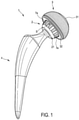
- Fig. 1
- zeigt in schematischer Perspektivdarstellung eine Ausführungsform einer erfindungsgemäßen Kugelgelenkendoprothese in Form einer Hüftendoprothese,
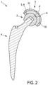
- Fig. 2
- die Kugelgelenkendoprothese nach
Fig. 1 in einer schematischen Längsschnittdarstellung, - Fig. 3
- in schematischer Perspektivdarstellung ein nicht gemäß der Erfindung gestalteter Kugelgelenkkopf nach dem Stand der Technik für eine Kugelgelenkendoprothese,
- Fig. 4, 5
- in unterschiedlichen schematischen Perspektivdarstellungen eine Ausführungsform eines erfindungsgemäßen Kugelgelenkkopfs der Kugelgelenkendoprothese nach den
Fig. 1 und2 und - Fig. 6
- eine schematische Querschnittsdarstellung des Kugelgelenkkopfs nach den
Fig. 4 und 5 entlang einer äquatorialen Schnittebene. - Gemäß den
Fig. 1 und2 ist eine Kugelgelenkendoprothese 1 als künstlicher Gelenkersatz für ein menschliches Kugelgelenk vorgesehen und weist einen Kugelgelenkkopf 2 und eine Kugelgelenkpfanne 3 auf. - Bei der gezeigten Ausführungsform ist die Kugelgelenkendoprothese 1 in Form einer Hüftendoprothese gestaltet, die auch als Hüftimplantat bezeichnet werden kann. Der Kugelgelenkkopf 2 kann insoweit auch als künstlicher Hüftkopf bezeichnet werden. Die Kugelgelenkpfanne 3 kann dementsprechend als künstliche Hüftpfanne bezeichnet werden.
- Mit Ausnahme der nachfolgend noch näher beschriebenen erfindungsgemäßen Gestaltung des Kugelgelenkkopfs 2 weist die Kugelgelenkendoprothese 1 eine dem Fachmann grundsätzlich bekannte räumlich-körperliche Gestaltung und Funktionsweise auf, so dass auf eine ausführliche diesbezügliche Beschreibung verzichtet werden kann. Kurz gefasst ist festzuhalten, dass die Kugelgelenkpfanne 3 zur beckenseitigen Fixierung vorgesehen ist. Der Kugelgelenkkopf 2 ist dementgegen zur femurseitigen Fixierung vorgesehen. Zu diesem Zweck ist der Kugelgelenkkopf 2 einends auf eine dem Fachmann bekannte Weise an einem Kugelgelenkschaft 4 angeordnet, der auch als künstlicher Hüftschaft bezeichnet werden kann. Der Kugelgelenkschaft 4 wird auf bekannte Weise in den Femurschaft des Patienten eingesetzt.
- Bei der gezeigten Ausführungsform ist die Kugelgelenkpfanne 3 mehrteilig gestaltet und weist ein Schalenteil 31, das auch als Hüftpfannenschale bezeichnet werden kann, und ein Inlayteil 32, das auch als Hüftpfanneneinsatz bezeichnet werden kann, auf. Eine solche mehrteilige Gestaltung der Kugelgelenkpfanne 3 ist im Hinblick auf die Erfindung als nicht wesentlich zu erachten.
- Der Kugelgelenkkopf 2 weist eine noch näher beschriebene konvexe Artikulationsfläche 5 auf, die kugelgelenkig artikulierend gleitbeweglich mit einer konkaven Artikulationsfläche 6 der Kugelgelenkpfanne 3 zusammenwirkt (
Fig. 2 ). - Die gleitbewegliche Artikulation zwischen dem Kugelgelenkkopf 2 und der Kugelgelenkpfanne 3, genauer: zwischen der konvexen Artikulationsfläche 5 und der konkaven Artikulationsfläche 6, ist naturgemäß reibungsbehaftet. Dementsprechend lassen sich ein Abrieb und damit einhergehend Verschleißerscheinungen nicht vollumfänglich vermeiden.
- Um dem entgegenzuwirken, weist der Kugelgelenkkopf 2 mehrere benachbart angeordnete und radial abgeflachte Abflachungsflächen 7a bis 7l auf (
Fig. 4, 5 ,6 ). Hierdurch ist die konvexe Artikulationsfläche 5 des Kugelgelenkkopfs 2 in Form einer modifizierten Kugelfläche K ausgebildet. Die modifizierte Kugelfläche K weist eine um die Abflachungsflächen 7a bis 7l reduzierte Oberfläche zur Artikulation mit der konkaven Artikulationsfläche 6 der Kugelgelenkpfanne 3 auf. Dabei ist die modifizierte Kugelfläche K kleiner als eine nichtmodifizierte Kugelfläche K' eines mit Ausnahme der Abflachungsflächen 7a bis 7l identisch gestalteten Kugelgelenkkopfs 2', wie er aus dem Stand der Technik bekannt und exemplarisch anhandFig. 3 gezeigt ist. - Wie insbesondere anhand
Fig. 6 ersichtlich ist, bilden die Abflachungsflächen 7a bis 7l nicht etwa Nuten, Einschnitte oder anderweitige konkave Einkerbungen an dem Kugelgelenkkopf 2 aus. Stattdessen sind die Abflachungsflächen 7a bis 7l plan, eben und/oder nicht konkav. Dies jedenfalls in Bezug auf eine Umfangsrichtung des Kugelgelenkkops 2. Hierdurch werden Rücksprünge und/oder scharfe Kanten an der konvexen Artikulationsfläche 5 vermieden. Dies im Unterschied zu aus dem Stand der Technik bekannten nutförmigen Einkerbungen des Kugelgelenkkopfs. In Bezug auf ihre jeweilige Haupterstreckungsrichtung sind die Abflachungsflächen 7a bis 7l entsprechend der kugelförmigen Kontur des Kugelgelenkkopfs 2 bzw. der modifizierten Kugelfläche K gekrümmt längserstreckt. AnhandFig. 6 ist zudem ersichtlich, dass der Kugelgelenkkopf 2 vorliegend mit einem Radius R ausgeführt ist. Dabei weisen die Abflachungsflächen 7a bis 7l - jedenfalls in Bezug auf die gezeigte Schnittebene - keinerlei Radius und somit weder eine konvexe noch eine konkave Krümmung auf. - Bei der gezeigten Ausführungsform weist die modifizierte Kugelfläche K im Vergleich zu der nicht-modifizierten Kugelfläche K' des nicht-abgeflachten und insoweit üblichen Kugelgelenkkopfs 2' (
Fig. 3 ) eine um 40 % reduzierte Oberfläche zur gleitbeweglichen Artikulation mit der konkaven Artikulationsfläche 6 auf. Mit anderen Worten ausgedrückt, findet zwischen den Abflachungsflächen 7a bis 7l und der konkaven Artikulationsfläche 6 kein gleitbeweglicher Kontakt statt, wodurch die wirksame Kontaktfläche des Kugelgelenkkopfs 2 entsprechend reduziert ist. - Bei zeichnerisch nicht dargestellten Ausführungsformen ist die modifizierte Kugelfläche vergleichsweise um 25 % bis 50 % gegenüber einer im Durchmesser identischen, nicht-abgeflachten Kugelfläche reduziert.
- Vorliegend sind die Abflachungsflächen 7a bis 7l in Umfangsrichtung U des Kugelgelenkkopfs 2 gleichmäßig beabstandet angeordnet (
Fig. 4, 5 ,6 ). Bei einer zeichnerisch nicht dargestellten Ausführungsform ist stattdessen eine ungleichmäßige Beabstandung vorgesehen. - Zudem sind die Abflachungsflächen 7a bis 7l vorliegend jeweils ausgehend von einem unterseitigen Schaftbereich 21 des Kugelgelenkkopfs 2 bis in einen oberseitigen Polbereich 22 des Kugelgelenkkopfs 2 durchgängig längserstreckt. Hierdurch bilden die Abflachungsflächen 7a bis 7l im Zusammenwirken mit der konkaven Artikulationsfläche 6 jeweils einen durchgängig längserstreckten Kapillarspalt S aus (
Fig. 1 ). Dabei ist anhandFig. 1 aus Gründen der Übersichtlichkeit lediglich einer der mehreren Kapillarspalte mittels des dortigen Bezugszeichens "S" gekennzeichnet. Es versteht sich, dass entsprechend der Anzahl der Abflachungsflächen 7a bis 7l mehrere in Umfangsrichtung des Kugelgelenkkopfs 2 benachbart angeordnete Kapillarspalte ausgebildet sind. Entlang der Kapillarspalte findet im implantierten Zustand der Kugelgelenkendoprothese 1 ein kapillarer Transport von Gelenkflüssigkeit statt. - Hierdurch kann eine verbesserte Schmierung der gleitbeweglichen Artikulation zwischen dem Kugelgelenkkopf 2 und der Kugelgelenkpfanne 3 erreicht werden. Dies vermindert dem reibungsbedingten Abrieb und damit den Verschleiß der Kugelgelenkendoprothese 1.
- Der kapillare Transport der Gelenkflüssigkeit wird durch eine entsprechende Dimensionierung der Abflachung der Abflachungsflächen 7a bis 7l ermöglicht. Um eine ausreichende kapillare Steighöhe der Gelenkflüssigkeit innerhalb der Kapillarspalte zu gewährleisten, sind die Abflachungsflächen 7a bis 7l bei der gezeigten Ausführungsform jeweils um 0,1 mm gegenüber der gedachten nicht-modifizierten Kugelfläche K' abgeflacht. Hierdurch wird ein hinreichend geringes Spaltmaß der Kapillarspalte erreicht. Bei einer zu starken, über wenige Zehntel Millimeter hinausgehenden Abflachung wird stattdessen ein Spaltmaß erreicht, das keinen oder jedenfalls keinen ausreichenden Kapillareffekt bewirkt.
- Bei zeichnerisch nicht dargestellten Ausführungsformen bewegt sich die Abflachung der Abflachungsfläche maßlich zwischen 0,03 mm und 0,3 mm.
- Vorliegend beziehen sich die vorstehenden maßlichen Angaben auf eine maximale Abflachung der Abflachungsflächen 7a bis 7l. Die maximale Abflachung ist bei der gezeigten Ausführungsform einends, an einem an den Schaftbereich 21 angrenzenden Stirnendbereich der jeweiligen Abflachungsfläche 7a bis 7l vorgesehen. Ausgehend von dort nimmt die Abflachung der Abflachungsflächen 7a bis 7l in Polrichtung P (
Fig. 6 ) des Kugelgelenkkopfs 2 kontinuierlich ab und geht im Polbereich 22 des Kugelgelenkkopfs 2 in die modifizierte Kugelfläche K über. Dies ist deutlich anhandFig. 5 ersichtlich. Mit anderen Worten ausgedrückt, verringert sich die Abflachung der Abflachungsflächen 7a bis 7l ausgehend von dem Schaftbereich 21 entlang der jeweiligen Haupterstreckungsrichtung und geht im Polbereich 22 gegen null. Infolge der sich kontinuierlich verringernden Abflachung weisen die Abflachungsflächen 7a bis 7l entlang ihrer jeweiligen Haupterstreckungsrichtung eine veränderliche Breite auf. Diese ist im Schaftbereich 21 maximal und im Polbereich 22 minimal. Dabei geht die besagte Breite im Polbereich 22 jeweils gegen null. - Bei der gezeigten Ausführungsform sind die Abflachungsflächen 7a bis 7l in Bezug auf die Polrichtung P gerade längserstreckt (
Fig. 6 ). - Bei zeichnerisch nicht dargestellten Ausführungsformen ist dementgegen eine winklige oder wendelförmige Längserstreckung der Abflachungsflächen vorgesehen.
- Vorliegend weist der Kugelgelenkkopf 2 insgesamt zwölf Abflachungsflächen 7a bis 7l auf. Diese sind um jeweils 30° in Umfangsrichtung des Kugelgelenkkopfs 2 zueinander versetzt angeordnet.
- Bei zeichnerisch dargestellten Ausführungsformen weist der Kugelgelenkkopf 2 zwischen zwei und 20 Abflachungsflächen auf.
- Die Abflachungsflächen 7a bis 7l können mittels abrasiver oder nicht-abrasiver Fertigungsverfahren an dem Kugelgelenkkopf 2 ausgebildet werden. Hierzu hat sich ein abschnittsweises Schleifen, insbesondere ein Planschleifen, des Kugelgelenkkopfs 2 als besonders vorteilhaft erwiesen.
Claims (11)
- Kugelgelenkendoprothese (1), insbesondere Hüftendoprothese, mit einem Kugelgelenkkopf (2), der eine konvexe Artikulationsfläche (5) aufweist, und mit einer Kugelgelenkpfanne (3), die eine konkave Artikulationsfläche (6) aufweist, wobei die konvexe Artikulationsfläche (5) und die konkave Artikulationsfläche (6) kugelgelenkig artikulierend gleitbeweglich zusammenwirken, dadurch gekennzeichnet, dass der Kugelgelenkkopf (2) mehrere benachbart angeordnete und radial abgeflachte Abflachungsflächen (7a bis 71) aufweist, wodurch die konvexe Artikulationsfläche (5) in Form einer modifizierten Kugelfläche (K) ausgebildet ist, die - im Vergleich zu einer gedachten nicht-modifizierten Kugelfläche (K') - eine um die Abflachungsflächen (7a bis 7l) reduzierte Oberfläche zur Artikulation mit der konkaven Artikulationsfläche (6) aufweist.
- Kugelgelenkendoprothese (1) nach Anspruch 1, dadurch gekennzeichnet, dass die modifizierte Kugelfläche (K) im Vergleich zu der gedachten nicht-modifizierten Kugelfläche (K') eine um 25 % bis 50 %, bevorzugt um 40 %, reduzierte Oberfläche zur Artikulation mit der konkaven Artikulationsfläche (6) aufweist.
- Kugelgelenkendoprothese (1) nach Anspruch 1 oder 2, dadurch gekennzeichnet, dass die Abflachungsflächen (7a bis 7l) in Umfangsrichtung (U) des Kugelgelenkkopfs (2) gleichmäßig beabstandet angeordnet sind.
- Kugelgelenkendoprothese (1) nach einem der vorhergehenden Ansprüche, dadurch gekennzeichnet, dass der Kugelgelenkkopf (2) zum Ausbilden der Abflachungsflächen (7a bis 7l) abschnittsweise plan geschliffen ist.
- Kugelgelenkendoprothese (1) nach einem der vorhergehenden Ansprüche, dadurch gekennzeichnet, dass die Abflachungsflächen (7a bis 7l) jeweils in einer ersten Erstreckungsrichtung plan erstreckt sind und in einer senkrecht zu der ersten Erstreckungsrichtung orientierten zweiten Erstreckungsrichtung gekrümmt erstreckt sind.
- Kugelgelenkendoprothese (1) nach einem der vorhergehenden Ansprüche, dadurch gekennzeichnet, dass die Abflachungsflächen (7a bis 7l) jeweils ausgehend von einem unterseitigen Schaftbereich (21) des Kugelgelenkkopfs (2) bis in einen oberseitigen Polbereich (22) des Kugelgelenkkopfs (2) durchgängig längserstreckt sind, wodurch jeweils ein durchgängig längserstreckter Kapillarspalt (S) zum kapillaren Transport von Gelenkflüssigkeit ausgebildet ist.
- Kugelgelenkendoprothese (1) nach einem der vorhergehenden Ansprüche, dadurch gekennzeichnet, dass die Abflachungsflächen (7a bis 7l) um jeweils 0,03 mm bis 0,3 mm, bevorzugt um 0,1 mm, gegenüber der gedachten nicht-modifizierten Kugelfläche (K') abgeflacht sind.
- Kugelgelenkendoprothese (1) nach einem der vorhergehenden Ansprüche, dadurch gekennzeichnet, dass die Abflachungsflächen (7a bis 7l) in Polrichtung (P) des Kugelgelenkkopfs (2) jeweils abnehmend abgeflacht sind und im Polbereich (22) des Kugelgelenkkopfs (2) stetig in die modifizierte Kugelfläche (K) übergehen.
- Kugelgelenkendoprothese (1) nach einem der vorhergehenden Ansprüche, dadurch gekennzeichnet, dass die Abflachungsflächen (7a bis 7l) in Bezug auf die Polrichtung (P) des Kugelgelenkkopfs (2) jeweils gerade oder winklig oder wendelförmig längserstreckt sind.
- Kugelgelenkendoprothese (1) nach einem der vorhergehenden Ansprüche, dadurch gekennzeichnet, dass zwischen zwei und 20, bevorzugt zwölf, Abflachungsflächen (7a bis 7l) vorgesehen sind.
- Kugelgelenkkopf (2) für eine Kugelgelenkendoprothese (1) nach einem der vorhergehenden Ansprüche, mit einer konvexen Artikulationsfläche (5), die zur kugelgelenkigen gleitbeweglichen Artikulation mit einer konkaven Artikulationsfläche (6) einer Kugelgelenkpfanne (3) der Kugelgelenkendoprothese (1) vorgesehen ist, gekennzeichnet durch mehrere benachbart angeordnete und radial abgeflachte Abflachungsflächen (7a bis 7l), wodurch die konvexe Artikulationsfläche (5) in Form einer modifizierten Kugelfläche (K) ausgebildet ist, die - im Vergleich zu einer gedachten nicht-modifizierten Kugelfläche (K') - eine um die Abflachungsflächen (7a bis 7l) reduzierte Oberfläche zur Artikulation mit der konkaven Artikulationsfläche (6) aufweist.
Applications Claiming Priority (1)
| Application Number | Priority Date | Filing Date | Title |
|---|---|---|---|
| DE102020210033.0A DE102020210033A1 (de) | 2020-08-07 | 2020-08-07 | Kugelgelenkendoprothese |
Publications (2)
| Publication Number | Publication Date |
|---|---|
| EP3949906A1 true EP3949906A1 (de) | 2022-02-09 |
| EP3949906B1 EP3949906B1 (de) | 2025-05-07 |
Family
ID=77207092
Family Applications (1)
| Application Number | Title | Priority Date | Filing Date |
|---|---|---|---|
| EP21189595.8A Active EP3949906B1 (de) | 2020-08-07 | 2021-08-04 | Kugelgelenkendoprothese |
Country Status (2)
| Country | Link |
|---|---|
| EP (1) | EP3949906B1 (de) |
| DE (1) | DE102020210033A1 (de) |
Citations (5)
| Publication number | Priority date | Publication date | Assignee | Title |
|---|---|---|---|---|
| FR2795302B1 (fr) * | 1999-06-23 | 2001-12-28 | Rech S Et De Fabrication S E R | Prothese totale de la hanche |
| US20030171817A1 (en) * | 2000-04-06 | 2003-09-11 | Andre Rambert | Cotyloid insert for total hip prosthesis |
| WO2007069250A2 (en) * | 2005-12-14 | 2007-06-21 | Presrv Ltd. | Faceted long bone head prosthesis |
| US20080228282A1 (en) | 2007-03-14 | 2008-09-18 | John Brodowski | Artificial hip with grooved ball or cup for improved lubrication by capillary action |
| WO2013148434A1 (en) * | 2012-03-30 | 2013-10-03 | DePuy Synthes Products, LLC | Mobile bearing hip assembly having decoupled motion along multiple axes |
Family Cites Families (4)
| Publication number | Priority date | Publication date | Assignee | Title |
|---|---|---|---|---|
| US5916269A (en) | 1996-06-03 | 1999-06-29 | Depuy Orthopaedics, Inc. | Wear reduced acetabular component |
| DE102007031664B4 (de) | 2006-08-04 | 2018-07-26 | Ceramtec Gmbh | Strukturierte Oberfläche eines Kugelkopfes oder eines Pfanneneinsatzes eines künstlichen Hüftgelenkes zur Vermeidung des Trockenlaufs |
| US20120203351A1 (en) * | 2011-02-07 | 2012-08-09 | Thompson Daniel C | Extended life prosthetic hip joint |
| WO2014008284A1 (en) * | 2012-07-02 | 2014-01-09 | University Of Utah Research Foundation | Prosthetic joint |
-
2020
- 2020-08-07 DE DE102020210033.0A patent/DE102020210033A1/de active Pending
-
2021
- 2021-08-04 EP EP21189595.8A patent/EP3949906B1/de active Active
Patent Citations (5)
| Publication number | Priority date | Publication date | Assignee | Title |
|---|---|---|---|---|
| FR2795302B1 (fr) * | 1999-06-23 | 2001-12-28 | Rech S Et De Fabrication S E R | Prothese totale de la hanche |
| US20030171817A1 (en) * | 2000-04-06 | 2003-09-11 | Andre Rambert | Cotyloid insert for total hip prosthesis |
| WO2007069250A2 (en) * | 2005-12-14 | 2007-06-21 | Presrv Ltd. | Faceted long bone head prosthesis |
| US20080228282A1 (en) | 2007-03-14 | 2008-09-18 | John Brodowski | Artificial hip with grooved ball or cup for improved lubrication by capillary action |
| WO2013148434A1 (en) * | 2012-03-30 | 2013-10-03 | DePuy Synthes Products, LLC | Mobile bearing hip assembly having decoupled motion along multiple axes |
Also Published As
| Publication number | Publication date |
|---|---|
| EP3949906B1 (de) | 2025-05-07 |
| DE102020210033A1 (de) | 2022-02-10 |
Similar Documents
| Publication | Publication Date | Title |
|---|---|---|
| EP0998245B1 (de) | Pfanne für eine gelenkendoprothese | |
| DE60110108T2 (de) | Eine orthopädische gelenkprothese | |
| DE3223925C2 (de) | Implantierbares Ellbogengelenk | |
| EP1646334B1 (de) | Gelenkendoprothese | |
| EP0808619A2 (de) | Ellbogengelenk-Endoprothese | |
| EP1051132A1 (de) | Höhenvariierbares wirbelkörperimplantat | |
| EP1635974B1 (de) | Werkzeug zum entgraten | |
| DE4009360A1 (de) | Kniegelenk-endoprothese | |
| CH642250A5 (de) | Kugelgelenkkopf-prothese mit einer kappe. | |
| EP2259754B1 (de) | Knieendoprothese | |
| DE102012223475A1 (de) | Verfahren zum Bearbeiten eines Oberflächenbereichs eines Wälzlagerrings und Wälzlagerring sowie Wälzlager | |
| EP3921118B1 (de) | Honwerkzeug und feinbearbeitungsverfahren unter verwendung des honwerkzeugs | |
| EP1033108A1 (de) | Knochenraspel für eine Femurkopfprothese | |
| EP1164978A2 (de) | Blattartiger schaft einer hüftgelenkprothese für die verankerung im femur | |
| DE2742464A1 (de) | Koerpergelenksendoprothese | |
| WO2005072658A2 (de) | Zervikalprothese und instrumentarium | |
| EP3273913B1 (de) | Oberflächenersatzimplantat distaler humerus | |
| EP2106249B1 (de) | Hüftgelenkprothese | |
| EP3949906B1 (de) | Kugelgelenkendoprothese | |
| WO2017216039A1 (de) | Chirurgisches instrument mit abstandhaltendem schwenkelement | |
| WO2000064384A1 (de) | Endoprothese, insbesondere für ein künstliches hüftgelenk | |
| EP0390768A1 (de) | Knochenimplantat | |
| DE202011050062U1 (de) | Chirurgisches Instrument, chirurgisches Handstück und chirurgisches Antriebssystem | |
| WO2008015288A1 (de) | Strukturierte oberfläche eines kugelkopfes oder eines pfanneneinsatzes eines künstlichen hüftgelenkes zur vermeidung des trockenlaufs | |
| DE20011728U1 (de) | Tripolarer Kugelkopf für Hüftendoprothesen |
Legal Events
| Date | Code | Title | Description |
|---|---|---|---|
| PUAI | Public reference made under article 153(3) epc to a published international application that has entered the european phase |
Free format text: ORIGINAL CODE: 0009012 |
|
| STAA | Information on the status of an ep patent application or granted ep patent |
Free format text: STATUS: THE APPLICATION HAS BEEN PUBLISHED |
|
| AK | Designated contracting states |
Kind code of ref document: A1 Designated state(s): AL AT BE BG CH CY CZ DE DK EE ES FI FR GB GR HR HU IE IS IT LI LT LU LV MC MK MT NL NO PL PT RO RS SE SI SK SM TR |
|
| STAA | Information on the status of an ep patent application or granted ep patent |
Free format text: STATUS: REQUEST FOR EXAMINATION WAS MADE |
|
| 17P | Request for examination filed |
Effective date: 20220805 |
|
| RBV | Designated contracting states (corrected) |
Designated state(s): AL AT BE BG CH CY CZ DE DK EE ES FI FR GB GR HR HU IE IS IT LI LT LU LV MC MK MT NL NO PL PT RO RS SE SI SK SM TR |
|
| STAA | Information on the status of an ep patent application or granted ep patent |
Free format text: STATUS: EXAMINATION IS IN PROGRESS |
|
| 17Q | First examination report despatched |
Effective date: 20230704 |
|
| GRAP | Despatch of communication of intention to grant a patent |
Free format text: ORIGINAL CODE: EPIDOSNIGR1 |
|
| STAA | Information on the status of an ep patent application or granted ep patent |
Free format text: STATUS: GRANT OF PATENT IS INTENDED |
|
| RIC1 | Information provided on ipc code assigned before grant |
Ipc: A61F 2/30 20060101ALN20241223BHEP Ipc: A61F 2/36 20060101ALI20241223BHEP Ipc: A61F 2/34 20060101ALI20241223BHEP Ipc: A61F 2/32 20060101AFI20241223BHEP |
|
| INTG | Intention to grant announced |
Effective date: 20250117 |
|
| GRAS | Grant fee paid |
Free format text: ORIGINAL CODE: EPIDOSNIGR3 |
|
| GRAA | (expected) grant |
Free format text: ORIGINAL CODE: 0009210 |
|
| STAA | Information on the status of an ep patent application or granted ep patent |
Free format text: STATUS: THE PATENT HAS BEEN GRANTED |
|
| AK | Designated contracting states |
Kind code of ref document: B1 Designated state(s): AL AT BE BG CH CY CZ DE DK EE ES FI FR GB GR HR HU IE IS IT LI LT LU LV MC MK MT NL NO PL PT RO RS SE SI SK SM TR |
|
| REG | Reference to a national code |
Ref country code: GB Ref legal event code: FG4D Free format text: NOT ENGLISH |
|
| REG | Reference to a national code |
Ref country code: CH Ref legal event code: EP |
|
| REG | Reference to a national code |
Ref country code: DE Ref legal event code: R096 Ref document number: 502021007386 Country of ref document: DE |
|
| REG | Reference to a national code |
Ref country code: IE Ref legal event code: FG4D Free format text: LANGUAGE OF EP DOCUMENT: GERMAN |
|
| P01 | Opt-out of the competence of the unified patent court (upc) registered |
Free format text: CASE NUMBER: APP_23186/2025 Effective date: 20250515 |
|
| REG | Reference to a national code |
Ref country code: NL Ref legal event code: MP Effective date: 20250507 |
|
| PG25 | Lapsed in a contracting state [announced via postgrant information from national office to epo] |
Ref country code: PT Free format text: LAPSE BECAUSE OF FAILURE TO SUBMIT A TRANSLATION OF THE DESCRIPTION OR TO PAY THE FEE WITHIN THE PRESCRIBED TIME-LIMIT Effective date: 20250908 Ref country code: ES Free format text: LAPSE BECAUSE OF FAILURE TO SUBMIT A TRANSLATION OF THE DESCRIPTION OR TO PAY THE FEE WITHIN THE PRESCRIBED TIME-LIMIT Effective date: 20250507 Ref country code: FI Free format text: LAPSE BECAUSE OF FAILURE TO SUBMIT A TRANSLATION OF THE DESCRIPTION OR TO PAY THE FEE WITHIN THE PRESCRIBED TIME-LIMIT Effective date: 20250507 |
|
| PGFP | Annual fee paid to national office [announced via postgrant information from national office to epo] |
Ref country code: DE Payment date: 20250819 Year of fee payment: 5 |
|
| REG | Reference to a national code |
Ref country code: LT Ref legal event code: MG9D |
|
| PG25 | Lapsed in a contracting state [announced via postgrant information from national office to epo] |
Ref country code: NO Free format text: LAPSE BECAUSE OF FAILURE TO SUBMIT A TRANSLATION OF THE DESCRIPTION OR TO PAY THE FEE WITHIN THE PRESCRIBED TIME-LIMIT Effective date: 20250807 Ref country code: GR Free format text: LAPSE BECAUSE OF FAILURE TO SUBMIT A TRANSLATION OF THE DESCRIPTION OR TO PAY THE FEE WITHIN THE PRESCRIBED TIME-LIMIT Effective date: 20250808 |
|
| PG25 | Lapsed in a contracting state [announced via postgrant information from national office to epo] |
Ref country code: NL Free format text: LAPSE BECAUSE OF FAILURE TO SUBMIT A TRANSLATION OF THE DESCRIPTION OR TO PAY THE FEE WITHIN THE PRESCRIBED TIME-LIMIT Effective date: 20250507 Ref country code: PL Free format text: LAPSE BECAUSE OF FAILURE TO SUBMIT A TRANSLATION OF THE DESCRIPTION OR TO PAY THE FEE WITHIN THE PRESCRIBED TIME-LIMIT Effective date: 20250507 |
|
| PG25 | Lapsed in a contracting state [announced via postgrant information from national office to epo] |
Ref country code: BG Free format text: LAPSE BECAUSE OF FAILURE TO SUBMIT A TRANSLATION OF THE DESCRIPTION OR TO PAY THE FEE WITHIN THE PRESCRIBED TIME-LIMIT Effective date: 20250507 |
|
| PGFP | Annual fee paid to national office [announced via postgrant information from national office to epo] |
Ref country code: GB Payment date: 20250822 Year of fee payment: 5 |
|
| PG25 | Lapsed in a contracting state [announced via postgrant information from national office to epo] |
Ref country code: HR Free format text: LAPSE BECAUSE OF FAILURE TO SUBMIT A TRANSLATION OF THE DESCRIPTION OR TO PAY THE FEE WITHIN THE PRESCRIBED TIME-LIMIT Effective date: 20250507 |
|
| PGFP | Annual fee paid to national office [announced via postgrant information from national office to epo] |
Ref country code: AT Payment date: 20251020 Year of fee payment: 5 Ref country code: FR Payment date: 20250821 Year of fee payment: 5 |
|
| PG25 | Lapsed in a contracting state [announced via postgrant information from national office to epo] |
Ref country code: RS Free format text: LAPSE BECAUSE OF FAILURE TO SUBMIT A TRANSLATION OF THE DESCRIPTION OR TO PAY THE FEE WITHIN THE PRESCRIBED TIME-LIMIT Effective date: 20250807 |
|
| PGFP | Annual fee paid to national office [announced via postgrant information from national office to epo] |
Ref country code: IE Payment date: 20250821 Year of fee payment: 5 |
|
| PG25 | Lapsed in a contracting state [announced via postgrant information from national office to epo] |
Ref country code: IS Free format text: LAPSE BECAUSE OF FAILURE TO SUBMIT A TRANSLATION OF THE DESCRIPTION OR TO PAY THE FEE WITHIN THE PRESCRIBED TIME-LIMIT Effective date: 20250907 |
|
| PG25 | Lapsed in a contracting state [announced via postgrant information from national office to epo] |
Ref country code: LV Free format text: LAPSE BECAUSE OF FAILURE TO SUBMIT A TRANSLATION OF THE DESCRIPTION OR TO PAY THE FEE WITHIN THE PRESCRIBED TIME-LIMIT Effective date: 20250507 |
|
| PG25 | Lapsed in a contracting state [announced via postgrant information from national office to epo] |
Ref country code: SM Free format text: LAPSE BECAUSE OF FAILURE TO SUBMIT A TRANSLATION OF THE DESCRIPTION OR TO PAY THE FEE WITHIN THE PRESCRIBED TIME-LIMIT Effective date: 20250507 Ref country code: DK Free format text: LAPSE BECAUSE OF FAILURE TO SUBMIT A TRANSLATION OF THE DESCRIPTION OR TO PAY THE FEE WITHIN THE PRESCRIBED TIME-LIMIT Effective date: 20250507 |
|
| PG25 | Lapsed in a contracting state [announced via postgrant information from national office to epo] |
Ref country code: CZ Free format text: LAPSE BECAUSE OF FAILURE TO SUBMIT A TRANSLATION OF THE DESCRIPTION OR TO PAY THE FEE WITHIN THE PRESCRIBED TIME-LIMIT Effective date: 20250507 |
|
| PG25 | Lapsed in a contracting state [announced via postgrant information from national office to epo] |
Ref country code: EE Free format text: LAPSE BECAUSE OF FAILURE TO SUBMIT A TRANSLATION OF THE DESCRIPTION OR TO PAY THE FEE WITHIN THE PRESCRIBED TIME-LIMIT Effective date: 20250507 |
|
| PG25 | Lapsed in a contracting state [announced via postgrant information from national office to epo] |
Ref country code: SK Free format text: LAPSE BECAUSE OF FAILURE TO SUBMIT A TRANSLATION OF THE DESCRIPTION OR TO PAY THE FEE WITHIN THE PRESCRIBED TIME-LIMIT Effective date: 20250507 Ref country code: RO Free format text: LAPSE BECAUSE OF FAILURE TO SUBMIT A TRANSLATION OF THE DESCRIPTION OR TO PAY THE FEE WITHIN THE PRESCRIBED TIME-LIMIT Effective date: 20250507 |
|
| PG25 | Lapsed in a contracting state [announced via postgrant information from national office to epo] |
Ref country code: IT Free format text: LAPSE BECAUSE OF FAILURE TO SUBMIT A TRANSLATION OF THE DESCRIPTION OR TO PAY THE FEE WITHIN THE PRESCRIBED TIME-LIMIT Effective date: 20250507 |
|
| REG | Reference to a national code |
Ref country code: DE Ref legal event code: R097 Ref document number: 502021007386 Country of ref document: DE |
|
| PLBE | No opposition filed within time limit |
Free format text: ORIGINAL CODE: 0009261 |
|
| STAA | Information on the status of an ep patent application or granted ep patent |
Free format text: STATUS: NO OPPOSITION FILED WITHIN TIME LIMIT |
|
| REG | Reference to a national code |
Ref country code: CH Ref legal event code: L10 Free format text: ST27 STATUS EVENT CODE: U-0-0-L10-L00 (AS PROVIDED BY THE NATIONAL OFFICE) Effective date: 20260318 |
|
| REG | Reference to a national code |
Ref country code: CH Ref legal event code: H13 Free format text: ST27 STATUS EVENT CODE: U-0-0-H10-H13 (AS PROVIDED BY THE NATIONAL OFFICE) Effective date: 20260324 |
|
| PG25 | Lapsed in a contracting state [announced via postgrant information from national office to epo] |
Ref country code: MC Free format text: LAPSE BECAUSE OF FAILURE TO SUBMIT A TRANSLATION OF THE DESCRIPTION OR TO PAY THE FEE WITHIN THE PRESCRIBED TIME-LIMIT Effective date: 20250507 |
|
| 26N | No opposition filed |
Effective date: 20260210 |
|
| PG25 | Lapsed in a contracting state [announced via postgrant information from national office to epo] |
Ref country code: LU Free format text: LAPSE BECAUSE OF NON-PAYMENT OF DUE FEES Effective date: 20250804 |
|
| PG25 | Lapsed in a contracting state [announced via postgrant information from national office to epo] |
Ref country code: CH Free format text: LAPSE BECAUSE OF NON-PAYMENT OF DUE FEES Effective date: 20250831 |