EP3949806B1 - Systèmes et procédés pour une chaise portable munie d'un pare-soleil - Google Patents
Systèmes et procédés pour une chaise portable munie d'un pare-soleil Download PDFInfo
- Publication number
- EP3949806B1 EP3949806B1 EP21183217.5A EP21183217A EP3949806B1 EP 3949806 B1 EP3949806 B1 EP 3949806B1 EP 21183217 A EP21183217 A EP 21183217A EP 3949806 B1 EP3949806 B1 EP 3949806B1
- Authority
- EP
- European Patent Office
- Prior art keywords
- sunshade
- support frame
- chair
- poles
- collapsible
- Prior art date
- Legal status (The legal status is an assumption and is not a legal conclusion. Google has not performed a legal analysis and makes no representation as to the accuracy of the status listed.)
- Active
Links
- 238000000034 method Methods 0.000 title claims description 43
- 230000009977 dual effect Effects 0.000 claims description 89
- 239000004744 fabric Substances 0.000 claims description 8
- 238000009413 insulation Methods 0.000 claims description 2
- 239000000463 material Substances 0.000 description 63
- 238000005516 engineering process Methods 0.000 description 37
- 230000007246 mechanism Effects 0.000 description 29
- 239000012779 reinforcing material Substances 0.000 description 11
- 230000002787 reinforcement Effects 0.000 description 8
- 230000007704 transition Effects 0.000 description 3
- 235000013361 beverage Nutrition 0.000 description 2
- 230000015556 catabolic process Effects 0.000 description 2
- 239000002131 composite material Substances 0.000 description 2
- 238000006731 degradation reaction Methods 0.000 description 2
- 230000000881 depressing effect Effects 0.000 description 2
- 230000000694 effects Effects 0.000 description 2
- 230000017525 heat dissipation Effects 0.000 description 2
- 239000002184 metal Substances 0.000 description 2
- 229910052751 metal Inorganic materials 0.000 description 2
- 239000000853 adhesive Substances 0.000 description 1
- 230000001070 adhesive effect Effects 0.000 description 1
- 230000004075 alteration Effects 0.000 description 1
- 230000008901 benefit Effects 0.000 description 1
- 238000007664 blowing Methods 0.000 description 1
- 239000003086 colorant Substances 0.000 description 1
- 239000011152 fibreglass Substances 0.000 description 1
- 239000011521 glass Substances 0.000 description 1
- 230000010354 integration Effects 0.000 description 1
- 239000007788 liquid Substances 0.000 description 1
- 150000002739 metals Chemical class 0.000 description 1
- 238000012986 modification Methods 0.000 description 1
- 230000004048 modification Effects 0.000 description 1
- 238000000465 moulding Methods 0.000 description 1
- 239000004033 plastic Substances 0.000 description 1
- 230000003014 reinforcing effect Effects 0.000 description 1
- 230000000717 retained effect Effects 0.000 description 1
- 239000004576 sand Substances 0.000 description 1
- 230000000475 sunscreen effect Effects 0.000 description 1
- 239000000516 sunscreening agent Substances 0.000 description 1
- 238000003466 welding Methods 0.000 description 1
- 239000002023 wood Substances 0.000 description 1
Images


Classifications
-
- A—HUMAN NECESSITIES
- A47—FURNITURE; DOMESTIC ARTICLES OR APPLIANCES; COFFEE MILLS; SPICE MILLS; SUCTION CLEANERS IN GENERAL
- A47C—CHAIRS; SOFAS; BEDS
- A47C4/00—Foldable, collapsible or dismountable chairs
- A47C4/28—Folding chairs with flexible coverings for the seat or back elements
- A47C4/286—Folding chairs with flexible coverings for the seat or back elements foldable side to side and front to back, e.g. umbrella type
-
- A—HUMAN NECESSITIES
- A47—FURNITURE; DOMESTIC ARTICLES OR APPLIANCES; COFFEE MILLS; SPICE MILLS; SUCTION CLEANERS IN GENERAL
- A47C—CHAIRS; SOFAS; BEDS
- A47C7/00—Parts, details, or accessories of chairs or stools
- A47C7/62—Accessories for chairs
- A47C7/66—Means to protect against weather
Definitions
- Examples of the present disclosure relate to portable chairs that can be folded for transportation and storage and, more particularly, portable chairs having a sunshade.
- Portable chairs are commonly used to create a comfortable seating arrangement without needing to transport cumbersome furniture.
- Portable chairs typically consisting of lightweight poles and a metal or fabric seat, can be folded or otherwise collapsed to conveniently move the portable chair from one location to another. For example, many individuals use portable chairs outdoors during activities such as camping, attending sporting events, fishing, going to the beach, attending large outdoor gatherings, or other activities where sitting is desirable but chairs or other furniture are not normally present.
- portable chairs are often used outdoors, many users find themselves exposed to the sun's harmful rays while using the portable chair in locations where shade is unavailable (e.g., while at a sporting event or at the beach).
- One solution to this problem is to use a portable umbrella to provide shade by placing the umbrella near the portable chair.
- using a portable umbrella can be undesirable because it requires the user to transport additional items to the seating location and the umbrella is often unable to provide enough shade to adequately block the sun's harmful rays.
- the portable chairs are often used in locations where placing an umbrella near the portable chair may not be feasible (e.g., when using the chair on pavement where the umbrella cannot be inserted into the ground).
- US 6,193,308 B1 describes a collapsible chair with a table.
- two collapsible chair units are arranged abreast on the chair with a gap being defined between them.
- a rear vertical guide column extends in parallel to the inside back support column of each collapsible chair unit.
- the two collapsible chair units are coupled to each other into the collapsible single body by two auxiliary connectors, which are individually mounted to the top portion of both the inside back support column and an associated vertical guide column of each collapsible chair unit.
- a movable guide member is received in each guide column in a way such that the guide member is movable in a vertical direction under the guide of the guide column.
- US 7,243,990 B1 describes a sunshade apparatus for shading a chair, the sunshade apparatus having a pair of vertical support legs, a pair of attachment elements, a pair of horizontally extending arms, and a flexible canopy element for shading the chair.
- Each of the attachment elements is attached to a bottom end of one of the support legs and is adapted for mounting the sunshade apparatus on the chair.
- Each of the pair of horizontally extending arms is attached to one of the support legs with a hinge.
- a locking element functions to lock the pair of horizontally extending arms in the extended configuration with respect to the pair of vertical support legs.
- a folding element joins the horizontally extending arms and folds between a collapsed configuration wherein the arms are adjacent, and a spread configuration wherein the arms are laterally spaced.
- US 2007/236058 A1 describes a seating device which includes a frame and webbing bridging the frame to create a horizontal surface and back to support the torso of a user.
- the frame includes at least one tubular member oriented vertically as constituting at least a portion of the back of the seating device.
- a cylindrical pole having first and second ends is provided sized to telescope within the tubular member.
- a releaseable locking device is provided in conjunction with a tubular member for releaseably retaining the first end of the cylindrical pole within the tubular member and a functional device appended to the second end of the cylindrical pole.
- the functional device can include such items as umbrellas, flags, banners and shelters.
- the present invention provides a dual folding chair system as set out in claim 1.
- the present invention also provides a method of erecting a dual folding chair system as set out in claim 12.
- the plurality of adjustable brackets are configured to adjust the sunshade between a plurality of angles such that the plurality of sunshade support poles can be rotated substantially 90 and/or 180 degrees in relation to the plurality of vertical support poles between a deployed state and a collapsed state.
- Each of the plurality of adjustable brackets can include an adjustable angle bracket with a plurality of holes configured to receive a locking pin.
- each of the plurality of adjustable brackets can include an adjustable angle bracket with a plurality of holes configured to receive a spring-loaded releasable push button.
- each of the plurality of adjustable brackets can include bracket connections having raised edges that can be configured to align with raised edges of a corresponding bracket connection to prevent the sunshade support poles from moving in relation to the vertical support poles.
- the bracket connections when the raised edges of each bracket connection are aligned with the raised edges of the corresponding bracket connection, can be secured in place with a threaded connection.
- the bracket connections when the raised edges of each bracket connection are aligned with the raised edges of the corresponding bracket connection, can be secured in place with a spring-loaded tension knob.
- the collapsible sunshade support frame can be collapsed with the collapsible chair support frame while attached to the collapsible chair support frame. Similarly, the collapsible sunshade support frame can be deployed with the collapsible chair support frame while attached to the collapsible chair support frame.
- the plurality of chairs can include a breathable mesh material configured to facilitate heat dissipation.
- the plurality of fabric sections can include a reinforcing fabric proximate the collapsible chair support frame to provide support to the plurality of fabric sections.
- the dual folding chair system can include a compartment configured to hold objects when in a deployed state.
- the compartment can be a cooler configured to provide thermal insulation to an object stored within the compartment and include a top opening for a user to access the object within the cooler.
- the top opening can include a zipper, a hook and loop fastener, and/or a magnetic fastener.
- the compartment can include a pocket affixed to an outer surface of the cooler to hold an object.
- a method of erecting a dual folding chair system is defined in claim 12.
- Releasing a plurality of adjustable brackets of the sunshade frame can include loosening a plurality of twistable locks while engaging the plurality of adjustable brackets of the sunshade frame can include tightening the plurality of twistable locks.
- releasing a plurality of adjustable brackets of the sunshade frame can include removing a plurality of lock pins from the plurality of adjustable brackets while engaging the plurality of adjustable brackets of the sunshade frame can include inserting the plurality of lock pins into the plurality of adjustable brackets.
- releasing a plurality of adjustable brackets of the sunshade frame can include depressing a plurality of spring-loaded buttons of the plurality of adjustable brackets while engaging the plurality of adjustable brackets of the sunshade frame can include releasing the plurality of spring-loaded buttons.
- a method of folding a portable chair can include releasing a plurality of adjustable brackets of a sunshade frame, gripping a plurality of upper poles of the sunshade frame and lowering the plurality of upper poles until a sunshade reaches a collapsed position.
- the method can further include removing a plurality of vertical supports of the sunshade frame from a plurality of attachment brackets of the portable chair, gripping opposing ends of the sunshade frame and pushing inwardly until the sunshade frame is collapsed, and gripping opposing ends of the portable chair and pushing inwardly until the portable chair is collapsed.
- Releasing a plurality of adjustable brackets of the sunshade frame can include loosening a plurality of twistable locks of the plurality of adjustable brackets.
- releasing a plurality of adjustable brackets of the sunshade frame can include removing a plurality of lock pins from the plurality of adjustable brackets.
- releasing a plurality of adjustable brackets of the sunshade frame can include depressing a plurality of spring-loaded buttons of the plurality of adjustable brackets.
- a or “an” means “at least one” or “one or more.”
- the term “user”, “subject”, “end-user” or the like is not limited to a specific entity or person.
- references to “one embodiment”, “an embodiment”, or “embodiments” mean that the feature or features being referred to are included in at least one embodiment of the technology.
- references to “one embodiment”, “an embodiment”, or “embodiments” in this description do not necessarily refer to the same embodiment and are also not mutually exclusive unless so stated and/or except as will be readily apparent to those skilled in the art from the description.
- a feature, structure, act, etc. described in one embodiment may also be included in other embodiments but is not necessarily included.
- the current technology can include a variety of combinations and/or integrations of the embodiments described herein.
- the terms “about” or “approximately” for any numerical values or ranges indicate a suitable dimensional tolerance that allows the part or collection of components to function for its intended purpose as described herein. More specifically, “about” or “approximately” may refer to the range of values ⁇ 20% of the recited value, e.g. "about 90%” may refer to the range of values from 71% to 99%.
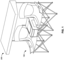
- FIG. 1 illustrates a perspective view of a dual chair 100 with sunshade 200, in accordance with an example of the disclosed technology.
- the dual chair 100 can be configured to support at least two users sitting upon the dual chair 100.
- the dual chair 100 is not so limited and can be configured to support three, four, five, or more users as would be suitable for the particular application. Accordingly, it is to be understood that the dual chair 100 can provide a convenient sitting arrangement for multiple people.
- the dual chair 100 and sunshade 200 is configured to transition between a deployed state (as depicted in FIG. 1 ) and a folded state such that the dual chair 100 and the sunshade 200 can be moved with relative ease from one location to another.
- the dual chair 200 can be folded and moved to a location where furniture is not normally available such as the beach, a sporting event, campsite, or other location. Furthermore, because the dual chair 100 and sunshade 200 can be folded, the dual chair 100 and sunshade 200 can be easily stored when not in use. As will become apparent throughout this disclosure, the sunshade 200 can be configured to be removed from the dual chair 100 such that the dual chair 100 and sunshade 200 can be used, moved, and/or stored separately, further adding to the ease of using the dual chair 100 and sunshade 200.
- the sunshade 200 is configured to be positioned above the dual chair 100 such that a user of the dual chair 100 can be shaded by the sunshade 200. Accordingly, the sunshade 200 can provide shade for a user seated upon the dual chair 100 without the need for the user to transport and set up a separate umbrella. Furthermore, as illustrated in FIGs. 1 , 2 , and 3 , the sunshade 200 is a substantially planar and substantially rectangular shape configured to provide shade to a user of the dual chair 200. Unlike the common rounded umbrellas that are unable to shade a substantially rectangular shape without being oversized, the substantially rectangular shape of the sunshade 200 can provide sufficient shade without requiring an unnecessary amount of space.
- the sunshade 200 can be configured to be adjusted between a plurality of angles and heights such that sunshade 200 can be positioned to best provide shade to a user seated upon the dual chair 100.
- the sunshade 200 can be adjusted between a plurality of angles and heights, the sunshade 200 can be useful to provide privacy to a user of the dual chair 100.
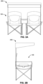
- FIG. 3 illustrates a perspective view of a dual chair 100, in accordance with an example of the disclosed technology.
- the dual chair 100 comprises a chair support frame 150 configured to support a plurality of material pieces which, together with the chair support frame 150, form the dual chair 100.
- the material pieces described herein can comprise material capable of being folded while also capable of supporting a user when the dual chair 100 is in a deployed state.
- the material pieces can comprise a fabric material, a plastic material, a cloth material, a mesh material, a composite material, or any other material capable of being folded and also supporting a user when in a deployed state.
- the material pieces can comprise an ornamental design having patterns, shapes, colors, trademarks, etc., and be treated with a solution to help prevent degradation caused by use of the dual chair 100 and exposure to wind, rain, sun, or other conditions that could degrade the material pieces.
- the material pieces can include a seat material 102, a reinforcing material 103, a breathable material 104, an arm rest 106, a cup holder 108, a center compartment 110, a cooler 112, a side pouch 114, a front pouch 116, a top shade 202, a side shade 204, and a sunshade reinforcement 206. It is to be understood that all material pieces described herein can comprise any of the materials previously described and can include an ornamental design and/or be treated with a solution to help prevent degradation as previously described.
- the seat material 102 is affixed to the chair support frame 150 and be configured to form a seat for the user to sit upon.
- the seat material 102 can be sized and shaped to support a user and distribute the load to the chair support frame 150 at locations where the seat material 102 is affixed to the chair support frame 150.
- the seat material 102 can be sized and shaped to form an ergonomic shape such that the dual chair 100 can provide a comfortable seat for a user.
- the seat material 102 can comprise at least two seat materials 102 such that the two seat materials 102 can provide at least two seats for a user to rest upon.
- the seat material 102 can be configured to attach to the chair support frame 150 via a reinforcing material 103.
- the reinforcing material 103 can be affixed to the seat material 102 in locations where the seat material 102 is affixed to the chair support frame 150.
- the reinforcing material 103 can be the same material as the seat material 102.
- the reinforcing material 103 can be multiple layers of the same type of material used to form the seat material 102.
- the reinforcing material 103 can be a different type of material affixed to the seat material 102 and configured to reinforce the seat material 102.
- the reinforcing material 103 can be configured to help distribute the load created by the user sitting upon the seat material 102 to the chair support frame 150. By adding the reinforcing material 103 to locations where the seat material 102 is affixed to the chair support frame 150, the reinforcing material 103 can help to prevent the seat material 102 from tearing or ripping when a load is applied.
- the reinforcing material 103 can be affixed to the seat material 102 by stitching, adhesives, fusing, welding, molding, or by any other sufficient method of affixing the reinforcing material 103 to the seat material.
- the seat material 102 can be affixed to a breathable material 104.
- the breathable material 104 can be affixed to the seat material 102 in locations where it would be advantageous to dissipate heat created by a user seated upon the dual chair 100.
- the breathable material 104 can be affixed to the seat material 102 proximate a location where the user's back and/or backside would be located when seated upon the dual chair 100.
- the breathable material 104 can help to provide a comfortable experience for a user seated upon the dual chair 100.
- the dual chair 100 can include an arm rest 106 affixed to the chair support frame 150.
- the arm rest 106 can be configured to support the arm of a user when the user is seated upon the dual chair 100.
- the arm rest 106 can also be configured to adjust between a plurality of heights to provide a comfortable experience for a user seated upon the dual chair 100.
- the arm rest 106 can be configured to include a cup holder 108 such that a user may place a drink, food, or other objects into the cup holder 108.
- the cup holder 108 can be sized and shaped to receive a cup, glass, bottle, or other container configured to contain a beverage or food such that the user is able to easily access the beverage or food.
- the dual chair 100 can include a center compartment 110 positioned between at least two chairs formed by the seat material 102.
- the center compartment 110 can be sized and positioned to provide an additional rest for a user's arm in addition to the arm rest 106.
- the center compartment 110 can also be configured to include a center compartment 112, a side pouch 114, and a front pouch 116. As will become apparent throughout this disclosure, the center compartment 110 can provide a convenient storage or holding location for objects the user would like to store.
- the center compartment 112 can a compartment configured to hold an object or multiple objects sized to fit within the center compartment 112.
- the center compartment 112 can be sized to receive food, toys, books, electronic devices, sunscreen, or any other object that a user would wish to store within the center compartment 112.
- the center compartment 112 can be thermally insulated to thermally insulate the contents of the center compartment 112 from the ambient conditions.
- the center compartment 112 can be a cooler configured to help keep contents within the center compartment 112 cool.
- the center compartment 112 can be a compartment configured to keep the contents within the center compartment 112 warm, such as heated food.
- the center compartment 112 can comprise a flap or lid configured to help retain and/or thermally insulate the objects within the center compartment 112.
- the center compartment 112 can include a zipper, a hook-and-loop fastener, a draw string, magnets, or other devices configured to help keep the center compartment 112 closed.
- the center compartment 112 can include one or more side pouches 14 and one or more front pouches 116.
- the side pouch 114 and the front pouch 116 can each comprise a simple pocket sewn into the side or the front of the center compartment 112.
- the side pouch 114 and/or the front pouch 116 can be sized to receive various objects such as a magazine, an electronic device, a toy, a book, etc.
- the side pouch 114 and/or the front pouch 116 can comprise a waterproof pouch configured to protect the contents from liquid and sand that could damage the contents of the side pouch 114 and/or the front pouch 116.
- the side pouch 114 and/or the front pouch 116 can include a zipper, a hook-and-loop fastener, a drawstring, magnets, or other devices configured to help keep the side pouch 114 and/or the front pouch 116 closed.
- the side pouch 114 and/or the front pouch 116 can be thermally insulated similar to the center compartment 112.
- FIG. 4 illustrates a perspective view of a sunshade 200, in accordance with an example of the disclosed technology.
- the sunshade 200 can include a top shade 202 and a plurality of side shades 204 supported by, and affixed to, a sunshade support frame 250 such that the sunshade 200 can be configured to provide shade to a user of the dual chair 100.
- the top shade 202 is substantially planar and substantially rectangular to provide shade to the user.
- the top shade 202 and the plurality of side shades 204 can be or include the same materials, ornamental design, and/or treatment solution, etc. as the material pieces previously described.
- the sunshade 200 can serve the dual purpose of deflecting rain or other moisture away from a user seated below the sunshade 200.
- the top shade 202 and the plurality of side shades 204 can comprise an opaque material such that the sunshade 200 can provide privacy to a user of the dual chair 100.
- the plurality of side shades 204 can be affixed to the top shade 202 and extend downwardly from the top shade 202 to further provide shade to a user seated upon the dual chair 100.
- the side shade 204 can extend downwardly from the top shade 202 a few inches on all sides of the top shade 202.
- the side shade 204 can extend downwardly from the top shade 202 a few inches on a front side of the top shade 202 and several inches or feet on the sides and back of the top shade 202.
- the side shade 204 can extend downwardly from the top shade 202 on a side of the top shade 202 such that the side shade 204 is shorter proximate the front of the top shade 202 and longer proximate the back of the top shade 202.
- the plurality of side shades 204 can also be configured to be adjustable such that a user can extend or retract the side shades 204.
- the side shades 204 can be configured to be rolled up and retained by straps when not in use.
- the side shades 204 can be configured to be extended downwardly when in use.
- the plurality of side shades 204 can be configured to be secured in place (e.g., with straps, hook-and-loop fasteners, zippers, etc.) when in use such that the side shades 204 are prevented from blowing in the wind or otherwise being moved from place.
- the sunshade 200 can include a sunshade reinforcement material 206 configured to retain the sunshade 200 in place on the sunshade support frame 250.
- the sunshade reinforcement material 206 can comprise the same material as the top shade 202 and the side shade 204, or the sunshade reinforcement material 206 can be a different material affixed to the top shade 202 and/or the side shade 204.
- the sunshade reinforcement material 206 can be configured to create a sleeve or pocket for a portion of the sunshade support frame 250 be inserted into.
- the sunshade reinforcement material 206 can be a strap of material configured retain the sunshade 200 in place.
- the sunshade reinforcement material 206 can be located proximate an end of the sunshade support frame 250 such that when a force is applied to the top shade 202 or the side shade 204, the sunshade reinforcement material 206 helps to prevent the top shade 202 or side shade 204 from being ripped, torn, or otherwise damaged.
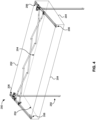
- FIG. 5 illustrates a perspective view of a dual chair support frame 150 and a sunshade support frame 250 in a deployed state, in accordance with an example of the disclosed technology.
- the sunshade support frame 250 can be configured to attach to the dual chair support frame 150 such that the dual chair support frame 150 can support the sunshade support frame 250.
- the sunshade 200 can be configured to provide shade to a user seated upon the dual chair 100 without requiring a separate support or stand for the sunshade 200.
- the sunshade support frame 250 can be removeably attached to the chair support frame 150 such that the sunshade 200 can be removed from the dual chair 100.
- the chair support frame 150 and sunshade support frame 250 are configured to move between a deployed state (as depicted in FIG. 5 ) or a folded state (as depicted in FIG. 6A ) together such that the dual chair 100 and sunshade 200 can be folded, transported, stored, and/or deployed together without needing to remove the sunshade 200.
- the sunshade support frame 250 can be removed from the chair support frame 150 such that sunshade support frame 250 and the chair support frame 150 can be individually folded, transported, stored and/or deployed (see FIGs. 7A-8C ).
- the chair support frame 150 includes a plurality of support poles 152 joined by pinned connections 154, pinned corner connections 156, sliding connections 158, sliding corner connections 160, and/or telescoping support poles 162 such that the plurality of support poles 152 can be affixed to each other and move in relation to each other.
- the chair support frame 150 can move between a folded state and a deployed state.
- the support poles 152 can be made of material configured to support the weight of a user while also remaining relatively lightweight such that a user can tote the dual chair 100 without excessive effort.
- the support poles 152 can be made from various lightweight metals, wood, composite materials, fiberglass, or any other suitable material for the application.
- the support poles can be configured to move in relation to each other in various ways.
- one or more support poles 152 can be configured to rotate about a pinned connection 154.
- one or more support poles 152 can be configured to rotate about a pinned corner connection 156.
- the sliding connections 158 can be configured to slide along the length of a support pole 152.
- the sliding corner connections 160 can be configured such that one or more support poles can remained connected to the sliding corner connection 160 while by rotating about a pinned joint of the sliding corner connection 160 while the sliding corner connection 160 slides along a support pole 152.
- the chair support frame 150 can include telescoping support poles 162 configured to include a support pole 152 with a large diameter and one or more support poles 152 with smaller diameters. In this way, the smaller telescoping support poles 152 can slide in and out of the larger telescoping support poles 152.
- the chair support frame 150 can be configured to include some or all of the elements just described to facilitate transitioning between a deployed state and a folded state.
- the various elements just described can be configured such that the dual chair 100 can be configured to support a user when the user is seated upon the dual chair 100.
- the sunshade support frame 250 can be configured to attach to the chair support frame 150 at a sunshade connection point 164.
- FIG. 6B illustrates a detailed section view of an example sunshade connection point 164, in accordance with an example of the disclosed technology.
- the chair support frame 150 can include the sunshade connection point 164 to receive the sunshade support frame 250 such that the chair support frame 150 can support the sunshade support frame 250.
- the sunshade connection point 164 can be sized to receive a vertical support pole 252 of the sunshade support frame 250.
- the vertical support pole 252 can include a simple spring locking pin 253 configured to insert into a corresponding hole or slot on the sunshade connection point 164 such that the vertical support pole 252 is prevented from sliding out of the sunshade connection point 164.
- the sunshade connection point 164 can be sized to include multiple holes or slots such that the vertical support pole 252 can be inserted further into the sunshade connection point 164 by pushing in the spring locking pin 253. In this way, the sunshade connection point 164 can facilitate adjustment of the sunshade 200 between various heights above the chair support frame 150.
- the sunshade connection point 164 depicted in FIG. 6B is offered only as an example sunshade connection point 164 and many other example sunshade connection points 164 could be used in place of the sunshade connection point 164 shown in FIG. 6B and described herein.
- the sunshade connection point 164 can be used without the spring locking pin 253 and simply comprise a vertical support pole 254 sized to slide into or around the sunshade connection point 164 or even into or around a support pole 152 of the chair support frame 150.
- the sunshade connection point 164 could comprise a twistable knob configured to restrict movement of the vertical support pole 252 when tightened.
- the sunshade connection point 164 can be or include a threaded connection, a press fit connection, a clamp connection, or any other suitable connection capable of supporting the sunshade 200 and also releasing the sunshade 200 from the dual chair 100.
- the vertical support pole 252 can be configured with multiple telescoping pole sections configured to transition between an extended state and a collapsed state.
- the support pole 252 can comprise multiple spring locking pins 252 configured to be inserted into a hole or slot of the sunshade connection point 164.
- the sunshade support frame 250 can include vertical support poles 252 that can be affixed to sunshade support poles 254 via a sunshade adjustment mechanism 270.
- the sunshade support poles 254 can be joined to the sunshade extension poles 256 via sliding extension pole connections 260 that are configured to slide along a length of the sunshade support poles 254 to facilitate folding of the sunshade 200.
- the sunshade support poles 256 can be affixed to each other by pinned joints 258 such that the sunshade support poles 256 can extend to a deployed position (as depicted in FIG. 5 ) while also folding to a folded position (as depicted in FIG. 6A ).
- the vertical support poles 252, the sunshade support poles 254, and the sunshade extension poles 256 can each be made of the same material as the support poles 152 previously described.
- the sunshade support frame 250 can be configured to be removed from the chair support frame 150 and be transitioned between a deployed state (as depicted in FIG. 8A and 8C ) and a folded state (as depicted in FIG. 8B ) without the chair support frame 150.
- the sunshade adjustment mechanism 270 can be configured to be adjustable such that the angle between the sunshade support poles 254 and the vertical support poles 252 can be adjusted.
- FIG. 9A illustrates a detailed view of a sunshade adjustment mechanism 270, in accordance with an example of the disclosed technology.
- the sunshade adjustment mechanism 270 can be or include an adjustable bracket having a vertical support pole connection 272, a sunshade support pole connection 274, an adjustment knob 276, and an adjustment screw 278.
- the vertical support pole connection 272 and the sunshade support pole connection 274 can each be a bracket connection configured to be affixed to the vertical support poles 252 or the sunshade support poles 254 respectively.
- the vertical support pole connection 272 and the sunshade support pole connection 274 can include raised edges or "teeth" (as depicted in FIGs. 9C and 9D ) such that the raised edges of the vertical support pole connection 272 can interface with the raised edges of the sunshade support pole connection 274 to facilitate maintaining the sunshade 200 in place.
- FIG. 9B illustrates a section view of a sunshade adjustment mechanism 270 taken along section line 1-1 depicted in FIG. 9A , in accordance with an example of the disclosed technology.
- the sunshade adjustment mechanism 270 can include an adjustment knob 276 and an adjustment screw 278 that, together, can be loosened or tightened to facilitate adjustment of the angle of the sunshade 200.
- a user can twist the adjustment knob 276 to loosen the sunshade adjustment mechanism 270 such that a gap can be created between the raised edges of the vertical support pole connection 272 and the sunshade support pole connection 274 and angle of the sunshade support pole 254 can be adjusted in relation to the vertical support pole 252.
- the sunshade 200 is in a preferred position, the user can tighten the adjustment knob 276 to secure the sunshade 200 in place.
- the sunshade adjustment mechanism 270 just described is offered merely for explanatory purposes and other forms of adjustment mechanisms can be used in place of the sunshade adjustment mechanism 270 just described.
- the sunshade adjustment mechanism 270 can be or include locking pins configured to be inserted into a hole of the vertical support pole connection 272 and the sunshade support pole connection 274 to retain the sunshade 200 in place.
- the sunshade adjustment mechanism 270 can include one or more spring-loaded releasable push buttons or pins.
- the sunshade adjustment mechanism 270 can be or include a spring-loaded adjustment knob.
- the sunshade adjustment mechanism 270 can be or include a friction fit interface between the vertical support pole connection 272 and the sunshade support pole connection 274 that can be adjustable. Further still, an example sunshade mechanism 270 can include a locking collar, a magnetic alignment bracket, a strap, or any other suitable adjustment mechanism configured to adjust an angle of the sunshade 200. As one of skill in the art will appreciate, the sunshade adjustment mechanism 270 can be or include any connecting mechanism configured to allow a user to adjust an angle of the sunshade 200.
- the sunshade adjustment mechanism 270 can be configured for a user to adjust the sunshade 200 between a plurality of angles, including approximately 90 degrees between the vertical support pole connection 272 and the sunshade support pole connection 274, approximately 180 degrees between the vertical support pole connection 272 and the sunshade support pole connection 274, approximately 270 degrees between the vertical support pole connection 272 and the sunshade support pole connection 274, approximately 360 degrees between the vertical support pole connection 272 and the sunshade support pole connection 274, and any angle therebetween.
- the sunshade connection point 164 can include an adjustable connection mechanism such that an angle of the vertical support pole 252 can be adjusted in relation to the chair support frame 150. If the sunshade connection point 164 is an adjustable connection mechanism, the adjustable connection mechanism can be or include the same mechanism as described here in relation to the sunshade adjustment mechanism 270. As will be appreciated, if the sunshade connection point 164 is an adjustable connection mechanism, the sunshade 200 can be configured to be folded downward such that the sunshade 200 can be beside the dual chair 100 when in a folded state. This can help to facilitate storing and toting the dual chair 100 and sunshade 200 in a more compact manner.
- FIG. 10 is a flowchart illustrating a method 1000 of deploying a dual chair (e.g., dual chair 100) with sunshade (e.g., sunshade 200), in accordance with an example of the disclosed technology.
- the method 1000 can include a user gripping 1002 opposing ends of the portable chair and pulling outwardly until a plurality of chair are deployed and a sunshade frame is extended.
- the method 1000 can include releasing 1004 a plurality of adjustable brackets or connections of the sunshade frame, gripping 1006 a plurality of upper poles (e.g., sunshade support poles 254) of the of the sunshade frame and lifting the plurality of upper poles until a sunshade reaches a desirable angle.
- the method 1000 can also include engaging 1008 the plurality of adjustable brackets of the sunshade frame to retain the sunshade at the desirable angle.
- the method 1000 just described can be applied by a user to deploy a dual chair 100 and sunshade 200 from a folded state to a deployed state.
- the sunshade 200 can be attached to the dual chair 100 while in the folded state such that the user is not required to attach the sunshade 200 to the dual chair 100.
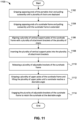
- FIG. 11 is a flowchart illustrating another method 1100 of deploying a dual chair (e.g., dual chair 100) with sunshade (e.g., sunshade 200), in accordance with an example of the disclosed technology.
- the method 1100 can include gripping 1102 opposing ends of the portable chair and pulling outwardly until a plurality of chairs are deployed.
- the method 1100 includes gripping 1104 opposing ends of a sunshade frame and pulling outwardly until the sunshade frame is extended.
- the method 1100 further includes aligning 1106 a plurality of vertical support poles of the sunshade frame with a plurality of attachment brackets of the plurality of chairs, inserting 1108 the plurality of vertical support poles into the plurality of attachment brackets, releasing 1110 a plurality of adjustable brackets of the sunshade frame, gripping 1112 a plurality of upper poles of the sunshade frame and lifting the plurality of upper poles until a sunshade reaches a desirable angle, and engaging 1114 the plurality of adjustable brackets of the sunshade frame to retain the sunshade at the desirable angle.
- the method 1100 just described can be applied by a user to deploy a dual chair 100 and sunshade 200 from a folded state to a deployed state.
- the sunshade 200 can be initially detached from the dual chair 100 while in the folded state. The user can then attach the sunshade 200 to the dual chair 100 to deploy the dual chair 100 and the sunshade 200.
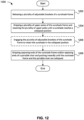
- FIG. 12 is a flowchart illustrating a method 1200 of folding a dual chair (e.g., dual chair 100) with sunshade (e.g., sunshade 200) which is not part of the claimed subject-matter.
- the method 1200 can include releasing 1202 a plurality of adjustable brackets of a sunshade frame and gripping 1204 a plurality of upper poles of the sunshade frame and lowering the plurality of upper poles until a sunshade reaches a collapsed position.
- the method 1200 can include engaging 1206 the plurality of adjustable brackets of the sunshade frame to retain the sunshade in the collapsed position.
- the method can further include gripping 1208 opposing ends of the sunshade frame and/or opposing ends of a portable chair and pushing inwardly until the sunshade frame and the portable chair are collapsed.
- the method 1200 just described can be applied by a user to fold a dual chair 100 and sunshade 200 from a deployed state to a folded state.
- the sunshade 200 can remain attached to the dual chair 100 such that the user is not required to detach the sunshade 200 from the dual chair 100.
- FIG. 13 is a flowchart illustrating another method 1300 of folding a dual chair (e.g., dual chair 100) with sunshade (e.g., sunshade 200) which is not part of the claimed subject-matter.
- the method 1300 can include releasing 1302 a plurality of adjustable brackets of a sunshade frame and gripping 1304 a plurality of upper poles of the sunshade frame and lowering the plurality of upper poles until a sunshade reaches a collapsed position.
- the method 1300 can include engaging 1306 the plurality of adjustable brackets of the sunshade frame to retain the sunshade in the collapsed position.
- the method 1300 can further include removing 1308 a plurality of vertical supports of the sunshade frame from a plurality of attachment brackets of the portable chair, gripping 1310 opposing ends of the sunshade frame and pushing inwardly until the sunshade is collapsed, and gripping 1312 opposing ends of the portable chair and pushing inwardly until the portable chair is collapsed.
- the method 1300 just described can be applied by a user to fold a dual chair 100 and sunshade 200 from a deployed state to a folded state.
- the sunshade 200 can be detached from the dual chair 100 when the user folds the dual chair 100 and sunshade 200.
- methods in accordance with the disclosed technology can include all or some of the steps described above and/or can include additional steps not expressly disclosed above. Further, methods in accordance with the disclosed technology can include some, but not all, of a particular step described above. Further still, various methods described herein can be combined in full or in part. That is, methods in accordance with the disclosed technology can include at least some elements or steps of a first method (e.g., method 1000) and at least some elements or steps of a second method (e.g., method 1100).
- a first method e.g., method 1000
- a second method e.g., method 1100
Landscapes
- Special Chairs (AREA)
Claims (13)
- Système de double chaise pliante comprenant :une première pluralité de poteaux de soutien rigides (152) reliés par des goupilles pour former un cadre de soutien de chaise pliable (150) ;une pluralité de sections de tissu (102, 103, 104) fixées à, et suspendues par le cadre de soutien de chaise pliable (150) pour former une pluralité de chaises, chaque chaise de la pluralité de chaises étant configurée pour soutenir un utilisateur lorsqu'elle est dans un état déployé ;une deuxième pluralité de poteaux de soutien rigides (252, 254, 256) reliés par des goupilles pour former un cadre de soutien de parasol pliable (250), la deuxième pluralité de poteaux de soutien rigides (252, 254, 256) comprenant une pluralité de poteaux de soutien verticaux (252) et une pluralité de poteaux de soutien de parasol (254) ;une section de tissu continue (202) fixée à, et soutenue par le cadre de soutien de parasol pliable (250) et configurée pour former un parasol sensiblement plat et sensiblement rectangulaire positionné au-dessus du cadre de soutien de chaise pliable (150) lorsqu'il est dans un état déployé ;une pluralité de points de liaison (164), le cadre de soutien de chaise pliable (150) comportant la pluralité de points de liaison (164), et la pluralité de points de liaison (164) étant configurés pour recevoir la pluralité de poteaux de soutien verticaux (252) du cadre de soutien de parasol pliable (250) de sorte que le cadre de soutien de parasol pliable (250) soit fixé de manière amovible au cadre de soutien de chaise pliable (150), etune pluralité de supports réglables (270) fixés à la pluralité de poteaux de soutien verticaux (252) et à la pluralité de poteaux de soutien de parasol (254), chacun de la pluralité de supports réglables (270) comprenant des liaisons de support ayant des bords surélevés, les bords surélevés de chaque liaison de support étant configurés pour s'aligner avec les bords surélevés d'une liaison de support correspondante pour empêcher les poteaux de soutien de parasol (254) de se déplacer par rapport aux poteaux de soutien verticaux (252),dans lequel la pluralité de supports réglables (270) sont configurés pour régler le parasol entre une pluralité d'angles.
- Système de la revendication 1, dans lequel la pluralité de supports réglables (270) sont configurés pour régler le parasol entre une pluralité d'angles de sorte que la pluralité de poteaux de soutien de parasol (254) puisse tourner sensiblement de 90 degrés par rapport à la pluralité de poteaux de soutien verticaux (252) entre un état déployé et un état replié.
- Système de la revendication 1 ou 2, dans lequel la pluralité de supports réglables (270) sont configurés pour régler le parasol entre une pluralité d'angles de sorte que la pluralité de poteaux de soutien de parasol (254) puisse tourner sensiblement de 180 degrés par rapport à la pluralité de poteaux de soutien verticaux (252).
- Système de l'une des revendications 1 à 3, dans lequel chacun de la pluralité de supports réglables (270) comprend un support d'angle réglable avec une pluralité de trous configurés pour recevoir une goupille de verrouillage.
- Système de l'une des revendications 1 à 4, dans lequel chacun de la pluralité de supports réglables (270) comprend un support d'angle réglable avec une pluralité de trous configurés pour recevoir un bouton-poussoir libérable à ressort.
- Système de la revendication 1, dans lequel les liaisons de support, lorsque les bords surélevés de chaque liaison de support sont alignés avec les bords surélevés de la liaison de support correspondante, sont configurées pour être fixées en place avec une liaison filetée (276, 278).
- Système de la revendication 1, dans lequel les liaisons de support, lorsque les bords surélevés de chaque liaison de support sont alignés avec les bords surélevés de la liaison de support correspondante, sont configurées pour être fixées en place avec un bouton de tension à ressort.
- Système de l'une des revendications 1 à 7, dans lequel le cadre de soutien de parasol pliable peut être replié avec le cadre de soutien de chaise pliable tout en étant fixé au cadre de soutien de chaise pliable.
- Système de l'une des revendications 1 à 8, dans lequel le cadre de soutien de parasol pliable (250) peut être déployé avec le cadre de soutien de chaise pliable (150) tout en étant fixé au cadre de soutien de chaise pliable (150).
- Système de l'une des revendications 1 à 9, comprenant en outre un compartiment (112) configuré pour contenir des objets lorsqu'il est dans un état déployé ; où le compartiment (112) comprend une glacière configurée pour fournir une isolation thermique à un objet stocké dans le compartiment, la glacière comprenant en outre une ouverture supérieure où un utilisateur peut accéder à l'objet dans la glacière.
- Système de la revendication 10, l'ouverture supérieure comprenant au moins l'une d'une fermeture à glissière, d'une fermeture autoagrippante et d'une fermeture magnétique.
- Procédé (1100) de montage d'un système de double chaise pliante tel que défini dans l'une des revendications 1 à 11, le procédé comprenant les étapes consistant à :saisir (1102) les extrémités opposées du cadre de soutien de chaise pliable (150) et tirer vers l'extérieur jusqu'à ce qu'une pluralité de chaises soient déployées ;saisir (1104) les extrémités opposées du cadre de soutien de parasol (250) et tirer vers l'extérieur jusqu'à ce que le cadre de soutien de parasol soit étendu ;aligner (1106) la pluralité de poteaux de soutien verticaux (252) du cadre de soutien de parasol avec la pluralité de points de liaison (164) de la pluralité de chaises ;insérer (1108) la pluralité de poteaux de soutien verticaux (252) dans la pluralité de points de liaison (164) ;libérer (1110) la pluralité de supports réglables (270) du cadre de soutien de parasol ;saisir (1112) la pluralité de poteaux de soutien de parasol (254) du cadre de soutien de parasol et soulever la pluralité de poteaux de soutien de parasol (254) jusqu'à ce que le parasol atteigne un angle souhaitable ; etengager (1114) la pluralité de supports réglables (270) du cadre de soutien de parasol pour retenir le parasol à l'angle souhaitable.
- Procédé de la revendication 12, dans lequel la libération de la pluralité de supports réglables (270) du cadre de soutien de parasol comprend le desserrage d'une pluralité de verrous rotatifs de la pluralité de supports réglables, et dans lequel l'engagement de la pluralité de supports réglables du cadre de soutien de parasol comprend le serrage de la pluralité de verrous rotatifs.
Applications Claiming Priority (1)
| Application Number | Priority Date | Filing Date | Title |
|---|---|---|---|
| US16/986,089 US11350752B2 (en) | 2019-11-19 | 2020-08-05 | Systems and methods for a portable chair with sunshade |
Publications (2)
| Publication Number | Publication Date |
|---|---|
| EP3949806A1 EP3949806A1 (fr) | 2022-02-09 |
| EP3949806B1 true EP3949806B1 (fr) | 2023-11-22 |
Family
ID=76744743
Family Applications (1)
| Application Number | Title | Priority Date | Filing Date |
|---|---|---|---|
| EP21183217.5A Active EP3949806B1 (fr) | 2020-08-05 | 2021-07-01 | Systèmes et procédés pour une chaise portable munie d'un pare-soleil |
Country Status (2)
| Country | Link |
|---|---|
| EP (1) | EP3949806B1 (fr) |
| AU (1) | AU2021204428A1 (fr) |
Family Cites Families (5)
| Publication number | Priority date | Publication date | Assignee | Title |
|---|---|---|---|---|
| KR100311247B1 (ko) * | 1999-02-05 | 2001-11-02 | 황주환 | 착탈가능한 테이블이 일체로 구비된 절첩식 의자 |
| CA2501762A1 (fr) * | 2005-03-21 | 2006-09-21 | Innovative Sporting Products | Banc ou siege pliants avec auvent |
| US20070236058A1 (en) * | 2006-04-08 | 2007-10-11 | Yeider John O | Collapsible folding chair with umbrella |
| US7243990B1 (en) * | 2006-07-24 | 2007-07-17 | Gene Wahl | Sunshade apparatus |
| US8186755B2 (en) * | 2008-10-24 | 2012-05-29 | Bravo Sports | Collapsible canopy along with article of furniture and method incorporating the same |
-
2021
- 2021-06-29 AU AU2021204428A patent/AU2021204428A1/en active Pending
- 2021-07-01 EP EP21183217.5A patent/EP3949806B1/fr active Active
Also Published As
| Publication number | Publication date |
|---|---|
| AU2021204428A1 (en) | 2022-02-24 |
| EP3949806A1 (fr) | 2022-02-09 |
Similar Documents
| Publication | Publication Date | Title |
|---|---|---|
| US11350752B2 (en) | Systems and methods for a portable chair with sunshade | |
| US8186755B2 (en) | Collapsible canopy along with article of furniture and method incorporating the same | |
| US7243990B1 (en) | Sunshade apparatus | |
| US5582458A (en) | Portable lounge chair | |
| US7118172B1 (en) | Backpack chair | |
| US8091962B2 (en) | Folding canopy chair | |
| US6705334B2 (en) | Scriptured outdoor furniture | |
| US20130214565A1 (en) | Outdoor folding chair | |
| US20170181513A1 (en) | Multi-purpose modular travel and packaging bag | |
| AU2010330912B2 (en) | Collapsible shade device | |
| US7775587B1 (en) | Sport/pak/chair | |
| US20120217773A1 (en) | Combination Backpack-Luggage-Chair with Integral Lumbar Support | |
| US10206489B2 (en) | Multi-functional utility mat | |
| US9192235B2 (en) | iChair | |
| US20080018146A1 (en) | Sunshade apparatus | |
| US9894991B2 (en) | Unique portable foldable five-device-in-one kneeler-bench-caddy-table-umbrella system, having kneeler system, bench system, caddy system, table system, and kneeler-bench-caddy-table-locking umbrella system | |
| US20100078456A1 (en) | Camping gear with integral storage compartment | |
| US11707134B2 (en) | Packable chair for transporting containers | |
| WO2015013342A1 (fr) | Système et procédé d'ancrage de parasol | |
| US20070205640A1 (en) | Portable food holder for stadium seating | |
| US6666221B1 (en) | Combination chair and umbrella | |
| EP3949806B1 (fr) | Systèmes et procédés pour une chaise portable munie d'un pare-soleil | |
| EP3706595B1 (fr) | Armature de sac à dos | |
| WO2014074098A1 (fr) | Siège de stade pliable | |
| US20230363540A1 (en) | Packable chair |
Legal Events
| Date | Code | Title | Description |
|---|---|---|---|
| PUAI | Public reference made under article 153(3) epc to a published international application that has entered the european phase |
Free format text: ORIGINAL CODE: 0009012 |
|
| STAA | Information on the status of an ep patent application or granted ep patent |
Free format text: STATUS: THE APPLICATION HAS BEEN PUBLISHED |
|
| AK | Designated contracting states |
Kind code of ref document: A1 Designated state(s): AL AT BE BG CH CY CZ DE DK EE ES FI FR GB GR HR HU IE IS IT LI LT LU LV MC MK MT NL NO PL PT RO RS SE SI SK SM TR |
|
| STAA | Information on the status of an ep patent application or granted ep patent |
Free format text: STATUS: REQUEST FOR EXAMINATION WAS MADE |
|
| 17P | Request for examination filed |
Effective date: 20220714 |
|
| RBV | Designated contracting states (corrected) |
Designated state(s): AL AT BE BG CH CY CZ DE DK EE ES FI FR GB GR HR HU IE IS IT LI LT LU LV MC MK MT NL NO PL PT RO RS SE SI SK SM TR |
|
| STAA | Information on the status of an ep patent application or granted ep patent |
Free format text: STATUS: EXAMINATION IS IN PROGRESS |
|
| 17Q | First examination report despatched |
Effective date: 20230526 |
|
| GRAP | Despatch of communication of intention to grant a patent |
Free format text: ORIGINAL CODE: EPIDOSNIGR1 |
|
| STAA | Information on the status of an ep patent application or granted ep patent |
Free format text: STATUS: GRANT OF PATENT IS INTENDED |
|
| INTG | Intention to grant announced |
Effective date: 20230705 |
|
| P01 | Opt-out of the competence of the unified patent court (upc) registered |
Effective date: 20230823 |
|
| GRAS | Grant fee paid |
Free format text: ORIGINAL CODE: EPIDOSNIGR3 |
|
| GRAA | (expected) grant |
Free format text: ORIGINAL CODE: 0009210 |
|
| STAA | Information on the status of an ep patent application or granted ep patent |
Free format text: STATUS: THE PATENT HAS BEEN GRANTED |
|
| AK | Designated contracting states |
Kind code of ref document: B1 Designated state(s): AL AT BE BG CH CY CZ DE DK EE ES FI FR GB GR HR HU IE IS IT LI LT LU LV MC MK MT NL NO PL PT RO RS SE SI SK SM TR |
|
| REG | Reference to a national code |
Ref country code: GB Ref legal event code: FG4D |
|
| REG | Reference to a national code |
Ref country code: CH Ref legal event code: EP |
|
| REG | Reference to a national code |
Ref country code: DE Ref legal event code: R096 Ref document number: 602021006995 Country of ref document: DE |
|
| REG | Reference to a national code |
Ref country code: IE Ref legal event code: FG4D |
|
| REG | Reference to a national code |
Ref country code: LT Ref legal event code: MG9D |
|
| REG | Reference to a national code |
Ref country code: NL Ref legal event code: MP Effective date: 20231122 |
|
| PG25 | Lapsed in a contracting state [announced via postgrant information from national office to epo] |
Ref country code: GR Free format text: LAPSE BECAUSE OF FAILURE TO SUBMIT A TRANSLATION OF THE DESCRIPTION OR TO PAY THE FEE WITHIN THE PRESCRIBED TIME-LIMIT Effective date: 20240223 |
|
| PG25 | Lapsed in a contracting state [announced via postgrant information from national office to epo] |
Ref country code: IS Free format text: LAPSE BECAUSE OF FAILURE TO SUBMIT A TRANSLATION OF THE DESCRIPTION OR TO PAY THE FEE WITHIN THE PRESCRIBED TIME-LIMIT Effective date: 20240322 |
|
| PG25 | Lapsed in a contracting state [announced via postgrant information from national office to epo] |
Ref country code: LT Free format text: LAPSE BECAUSE OF FAILURE TO SUBMIT A TRANSLATION OF THE DESCRIPTION OR TO PAY THE FEE WITHIN THE PRESCRIBED TIME-LIMIT Effective date: 20231122 |
|
| REG | Reference to a national code |
Ref country code: AT Ref legal event code: MK05 Ref document number: 1633049 Country of ref document: AT Kind code of ref document: T Effective date: 20231122 |
|
| PG25 | Lapsed in a contracting state [announced via postgrant information from national office to epo] |
Ref country code: NL Free format text: LAPSE BECAUSE OF FAILURE TO SUBMIT A TRANSLATION OF THE DESCRIPTION OR TO PAY THE FEE WITHIN THE PRESCRIBED TIME-LIMIT Effective date: 20231122 |
|
| PG25 | Lapsed in a contracting state [announced via postgrant information from national office to epo] |
Ref country code: AT Free format text: LAPSE BECAUSE OF FAILURE TO SUBMIT A TRANSLATION OF THE DESCRIPTION OR TO PAY THE FEE WITHIN THE PRESCRIBED TIME-LIMIT Effective date: 20231122 |
|
| PG25 | Lapsed in a contracting state [announced via postgrant information from national office to epo] |
Ref country code: ES Free format text: LAPSE BECAUSE OF FAILURE TO SUBMIT A TRANSLATION OF THE DESCRIPTION OR TO PAY THE FEE WITHIN THE PRESCRIBED TIME-LIMIT Effective date: 20231122 |
|
| PG25 | Lapsed in a contracting state [announced via postgrant information from national office to epo] |
Ref country code: NL Free format text: LAPSE BECAUSE OF FAILURE TO SUBMIT A TRANSLATION OF THE DESCRIPTION OR TO PAY THE FEE WITHIN THE PRESCRIBED TIME-LIMIT Effective date: 20231122 Ref country code: LT Free format text: LAPSE BECAUSE OF FAILURE TO SUBMIT A TRANSLATION OF THE DESCRIPTION OR TO PAY THE FEE WITHIN THE PRESCRIBED TIME-LIMIT Effective date: 20231122 Ref country code: IS Free format text: LAPSE BECAUSE OF FAILURE TO SUBMIT A TRANSLATION OF THE DESCRIPTION OR TO PAY THE FEE WITHIN THE PRESCRIBED TIME-LIMIT Effective date: 20240322 Ref country code: GR Free format text: LAPSE BECAUSE OF FAILURE TO SUBMIT A TRANSLATION OF THE DESCRIPTION OR TO PAY THE FEE WITHIN THE PRESCRIBED TIME-LIMIT Effective date: 20240223 Ref country code: ES Free format text: LAPSE BECAUSE OF FAILURE TO SUBMIT A TRANSLATION OF THE DESCRIPTION OR TO PAY THE FEE WITHIN THE PRESCRIBED TIME-LIMIT Effective date: 20231122 Ref country code: BG Free format text: LAPSE BECAUSE OF FAILURE TO SUBMIT A TRANSLATION OF THE DESCRIPTION OR TO PAY THE FEE WITHIN THE PRESCRIBED TIME-LIMIT Effective date: 20240222 Ref country code: AT Free format text: LAPSE BECAUSE OF FAILURE TO SUBMIT A TRANSLATION OF THE DESCRIPTION OR TO PAY THE FEE WITHIN THE PRESCRIBED TIME-LIMIT Effective date: 20231122 Ref country code: PT Free format text: LAPSE BECAUSE OF FAILURE TO SUBMIT A TRANSLATION OF THE DESCRIPTION OR TO PAY THE FEE WITHIN THE PRESCRIBED TIME-LIMIT Effective date: 20240322 |