EP3949770A1 - Heating-type tobacco - Google Patents
Heating-type tobacco Download PDFInfo
- Publication number
- EP3949770A1 EP3949770A1 EP19920788.7A EP19920788A EP3949770A1 EP 3949770 A1 EP3949770 A1 EP 3949770A1 EP 19920788 A EP19920788 A EP 19920788A EP 3949770 A1 EP3949770 A1 EP 3949770A1
- Authority
- EP
- European Patent Office
- Prior art keywords
- tobacco
- heating
- strands
- type
- rod
- Prior art date
- Legal status (The legal status is an assumption and is not a legal conclusion. Google has not performed a legal analysis and makes no representation as to the accuracy of the status listed.)
- Withdrawn
Links
Images


Classifications
-
- A—HUMAN NECESSITIES
- A24—TOBACCO; CIGARS; CIGARETTES; SIMULATED SMOKING DEVICES; SMOKERS' REQUISITES
- A24D—CIGARS; CIGARETTES; TOBACCO SMOKE FILTERS; MOUTHPIECES OF CIGARS OR CIGARETTES; MANUFACTURE OF TOBACCO SMOKE FILTERS OR MOUTHPIECES
- A24D1/00—Cigars; Cigarettes
- A24D1/20—Cigarettes specially adapted for simulated smoking devices
Definitions
- the present invention relates to a heating-type tobacco.
- heating-type tobacco including a tobacco rod formed by filling the inside of wrapping paper with a tobacco filler containing a tobacco raw material (for example, tobacco shreds, tobacco granules, a reconstituted tobacco material, and the like) and an aerosol-source material (glycerin, propylene glycol, and the like) (refer to, for example, PTL 1).
- a heating-type tobacco of such a type is a tobacco article of a type that heats a tobacco filler by a heater of a heating device without burning the tobacco filler and delivers an aerosol generated at the tobacco filler to a user.
- the heater heaters having various shapes, such as a blade shape and a rod shape, have been practically used. The heater is inserted for use from the leading end surface of the tobacco rod, and the tobacco rod is thereby attached to the heating device.
- a tobacco raw material of a tobacco filler is oriented randomly.
- an aerosol generated as a result of an aerosol-source material being volatilized is easily condensed by being exposed to a low-temperature part of the randomly oriented tobacco raw material and is easily filtered by the tobacco raw material, and the delivery amount of the aerosol into an oral cavity may decrease.
- the inventors of the present application have discovered that it is possible to improve a tobacco rod for a conventional heating-type tobacco by employing a structure in which a large number of long tobacco strands obtained by forming a tobacco raw material into strand shapes are disposed to extend in the longitudinal direction of a tobacco rod.
- the present invention for solving the aforementioned problems is a heating-type tobacco including a tobacco rod that includes a tobacco filler and wrapping paper that wraps the tobacco filler.
- the tobacco filler includes a plurality of tobacco strands each of which is formed in a strand shape and is a tobacco raw material containing an aerosol-source material.
- the plurality of tobacco strands is aligned and disposed to extend in a longitudinal direction of the tobacco rod, and at least some of the tobacco strands are fixed to each other integrally.
- a fixed region portion in which at least some of the tobacco strands are fixed to each other integrally may be formed at only a specific portion of the tobacco rod in the longitudinal direction.
- the fixed region portion may be formed at a portion on a rear end side of the tobacco rod.
- a fixed region portion in which at least some of the tobacco strands are fixed to each other integrally may be formed in the tobacco rod over the entire length of the tobacco rod.
- At least some of the tobacco strands may be point-bonded to each other.
- a fixing agent that point-bonds at least some of the tobacco strands to each other may be dotted.
- the fixing agent may include at least one of carboxymethyl cellulose, polyvinyl alcohol, and ethylene-vinyl acetate copolymer resin.
- the fixed region portion may be formed to cover only a portion of a cross-section of the tobacco rod.
- the fixed region portion may be formed in only a specific region that is a portion of the cross-section of the tobacco rod, and the specific region may be set in the cross-section of the tobacco rod as a region that includes a heater insertion region into which a heater is inserted when the heating-type tobacco is attached to a heating device.
- the fixing agent that fixes at least some of the tobacco strands to each other in the fixed region portion may include at least one of calcium carbonate and sodium silicate.
- At least some of the tobacco strands may be coupled to each other via a tobacco coupling member formed by a tobacco raw material.
- the tobacco coupling member may couple portions on a rear end side of the tobacco strands to each other.
- the mouthpiece portion may further include a support portion that is disposed at a connection end connected to the base end side of the tobacco rod and that is for suppressing the tobacco strands from being pressed into a region on a side of the mouthpiece portion.
- a technique that is excellent in terms of the delivery amount of an aerosol that enables smooth insertion of a heater into a tobacco filler, and that can suppress a tobacco raw material from being pressed by the heater when the heater is inserted into the tobacco filler, in a heating-type tobacco that includes a tobacco rod including the tobacco filler containing the tobacco raw material and an aerosol-source material and wrapping paper that wraps the tobacco filler.
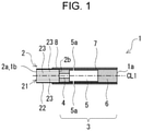
- Fig. 1 is a view schematically illustrating an internal structure of a heating-type tobacco 1 according to Embodiment 1.
- the heating-type tobacco 1 is a tobacco article of a type that heats a tobacco filler without burning the tobacco filler and delivers an aerosol generated at the tobacco filler to a user.
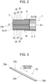
- Fig. 2 is a view illustrating an internal structure of a tobacco rod according to Embodiment 1.
- the sign CL1 in Fig. 1 indicates the center axis of the heating-type tobacco 1.
- the tobacco rod 2 and the mouthpiece portion 3 of the heating-type tobacco 1 are disposed coaxially, and the center axis CL1 can be considered as the center axis of the tobacco rod 2 and the mouthpiece portion 3.
- the sign 2a in Fig. 1 indicates a front end surface of the tobacco rod 2.
- the sign 2c indicates a rear end surface of the tobacco rod 2.
- the heating-type tobacco 1 air is inhaled by a user from the distal end 1b to the inhalation port end 1a through the heating-type tobacco 1.
- the distal end 1b of the heating-type tobacco 1 can be regarded as the distal end or the upstream end of the tobacco rod 2.
- the inhalation port end 1a of the heating-type tobacco 1 can be regarded as the rear end or the downstream end of the filter portion 6.
- the tobacco rod 2 is disposed at the distal end 1b of the heating-type tobacco 1.
- the tobacco rod 2 is a bar-shaped member wrapped by wrapping paper 22 such that a side surface of a tobacco filler 21 that contains a tobacco raw material and an aerosol-source material is covered.
- the tobacco filler 21 includes a plurality of tobacco strands 23 each of which is formed in a strand shape and is a tobacco raw material containing an aerosol-source material.
- the tobacco strands 23 are, for example, a tobacco raw material that is formed into a sheet-shaped tobacco sheet and shredded into strand shapes.
- strand shape denotes a long elongated shape, compared with a cross-section, extending in the longitudinal direction orthogonal to the direction of the cross-section and includes, for example, a strip shape, a string shape, a bar shape, and the like.
- the aerosol-source material contained in each tobacco strand 23 of the tobacco filler 21 is a substance that generates an aerosol when a volatile substance volatilized and emitted is cooled.
- the type of the aerosol-source material is not particularly limited, and substances extracted from various natural products can be selected, as appropriate, in accordance with intended uses.
- the aerosol-source material examples include glycerin, propylene glycol, triacetin, 1,3-butanediol, a mixture thereof, and the like.
- the tobacco strands 23 of the tobacco filler 21 may contain a flavor.
- the type of the flavor is not particularly limited.
- the front end surface 23a of the tobacco strand 23 is an end surface that faces the distal end 1b of the heating-type tobacco 1.
- the rear end surface 23b of the tobacco strand 23 is an end surface opposite to the front end surface 23a in the longitudinal direction (extension direction) of the tobacco strand 23.
- the rear end surface 23b of each tobacco strand 23 is disposed to face the front end surface of the support portion 4 disposed at the front end of the mouthpiece portion 3.
- the sign 23c in Fig. 3 indicates a side surface of the tobacco strand 23.
- the tobacco strands 23 aligned to extend in the longitudinal direction of the tobacco rod 2 are disposed with respective side surfaces 23c facing each other.
- the sign 25 in Fig. 2 indicates aerosol flow paths formed between the tobacco strands 23 in the longitudinal direction (the extension direction of the tobacco strands 23) of the tobacco rod 2.
- the tobacco strands 23 are, for example, a tobacco raw material that is formed into a sheet-shaped tobacco sheet and shredded into strand shapes and may be obtained by shredding a so-called reconstituted tobacco sheet into strand shapes.
- the reconstituted tobacco sheet may be, for example, a sheet obtained by adding a binding agent, a gelling agent, a crosslinking agent, a flavor, a viscosity modifier, a moisturizing agent, a reinforcement material, and the like as additives to a homogenized tobacco, kneading the homogenized tobacco, forming the homogenized tobacco into a sheet shape by an appropriate method, such as a paper making method (sheet making method), a casting method (slurry method), a rolling method, or an extruding method, and drying the homogenized tobacco.
- the homogenized tobacco is a tobacco material that is obtained by pulverizing, grinding, and mixing, for example, a leaf tobacco, dried tobacco leaves, tobacco shreds, an expanded tobacco, a
- the tobacco filler 21 for the tobacco rod 2 in the present embodiment is characterized in that at least some of the tobacco strands 23 are integrally fixed to each other.
- a form in which the tobacco strands 23 are fixed to each other by a fixing agent will be described here.
- the fixing agent is not particularly limited as long as being capable of fixing the tobacco strands 23 to each other, and various materials can be employed as the fixing agent.
- an aqueous solution containing calcium carbonate or an aqueous solution containing sodium silicate (soluble glass) is preferably employed as the fixing agent.
- the fixing agent may be an aqueous solution containing calcium carbonate and sodium silicate.
- the fixing agent an aqueous solution that contains at least one of CMC (carboxymethyl cellulose), PVA (polyvinyl alcohol), and EVA (ethylene-vinyl acetate copolymer resin).
- CMC carboxymethyl cellulose
- PVA polyvinyl alcohol
- EVA ethylene-vinyl acetate copolymer resin
- the fixing agent is added to the entirety of the tobacco filler 21 of the tobacco rod 2. Consequently, all of the tobacco strands 23 included in the tobacco filler 21 are integrated with each other.
- the region surrounded by the chain line indicated by the sign 24 in Fig. 2 is a fixed region portion.
- the fixed region portion 24 is a region in which the tobacco strands 23 are fixed to each other integrally via the fixing agent or the like. In the example illustrated in Fig. 2 , the fixed region portion 24 is formed at almost the entirety of the tobacco rod 2 (tobacco filler 21). However, as described later, only some of the tobacco strands 23 included in the tobacco filler 21 may be fixed to each other integrally by the fixing agent.
- Fig. 4 is a view for roughly describing an example of a state in which the tobacco strands 23 are fixed to each other in the fixed region portion 24 in the tobacco rod 2 (tobacco filler 21) according to Embodiment 1.
- the tobacco strands 23 are fixed (bonded) to each other via a fixing agent 27.
- the fixing agent 27 is a fixing agent sprayed onto the tobacco strands 23 in the production process of the tobacco rod 2 and cured.
- the fixing agent 27 is dotted in a region of the tobacco rod 2 (tobacco filler 21) and point-bonds (also referred to as "point-fix") one tobacco strand 23 to the other tobacco strand 23.
- the point bonding (point-fixing) referred here includes not only a form in which one tobacco strand 23 is bonded (fixed) in a dot manner to the other single tobacco strand 23 but also a form in which one tobacco strand 23 is bonded (fixed) to a plurality of the other tobacco strands 23 collectively.
- One tobacco strand 23 and the other tobacco strands 23 may be bonded (fixed) to each other at a plurality of portions of the tobacco rod 2 in the longitudinal direction by the fixing agent 27.
- the fixing agent 27 can point-bond the tobacco strands 23 to each other in a dot manner due to the fixing agent 27 being dotted in the fixed region portion 24 of the tobacco rod 2 (tobacco filler 21). It is possible by thus point-bonding the tobacco strands 23 to each other to integrally fix the tobacco strands 23 to each other while forming (remaining as gap portions) the aerosol flow paths 25 between the tobacco strands 23 aligned in the tobacco rod 2 (tobacco filler 21).
- the fixing agent 27 When a form in which the fixing agent 27 is thus dotted in the fixed region portion 24 is employed, it is particularly suitable to use CMC (carboxymethyl cellulose), PVA (polyvinyl alcohol), EVA (ethylene-vinyl acetate copolymer resin), or the like as the fixing agent 27.
- CMC carboxymethyl cellulose
- PVA polyvinyl alcohol
- EVA ethylene-vinyl acetate copolymer resin
- the fixing agent 27 by, for example, spraying the fixing agent 27 onto the fixed region portion 24 but is not limited thereto.
- the tobacco strands 23 may be fixed to each other by adding, to the fixed region portion 24, the fixing agent 27 that contains calcium carbonate or sodium silicate to the fixed region portion 24 to thereby form an adhesive layer in the fixed region portion 24.
- the support portion 4 is a segment positioned on the front end side of the mouthpiece portion 3.
- the support portion 4 is positioned on the immediate downstream side of the tobacco rod 2 and disposed in a state of being in contact with the rear end of the tobacco rod 2.
- the support portion 4 may be, for example, a hollow cellulose-acetate pipe body.
- the support portion 4 may be a columnar cellulose-acetate fiber bundle with a center hole formed at the center of a cross-section of the cellulose-acetate fiber bundle to pass therethrough.
- the support portion 4 may be a paper filter, a paper pipe, or the like filled with cellroll fibers. A paper pipe having a certain thickness can function effectively as the support portion 4.
- the support portion 4 is a segment for preventing the tobacco filler 21 from being pressed into the downstream side toward the cooling portion 5 in the heating-type tobacco 1 when an electric heater of a heating device to which the heating-type tobacco 1 is applied is inserted into the tobacco rod 2.
- the support portion 4 also functions as a spacer for spacing the cooling portion 5 of the heating-type tobacco 1 from the tobacco rod 2.
- the cooling portion 5 is positioned on the immediate downstream side of the support portion 4 and disposed in contact with the rear end of the support portion 4.
- a volatile substance emitted from the tobacco rod 2 flows along the cooling portion 5 toward the downstream side.
- the volatile substance that has been emitted from the tobacco rod 2 (tobacco filler 21) is cooled at the cooling portion 5 and thereby forms an aerosol that is to be inhaled by a user.
- the cooling portion 5 is formed of a hollow paper pipe having an air hole 5a through which outside air can be introduced.
- the cooling portion 5 may include a heat absorbing agent disposed not to obstruct the flow of the volatile substance and the aerosol.
- the cooling portion 5 may be formed by, for example, a filter material having a large number of flow paths (through holes) formed in the longitudinal direction (axial direction) of the mouthpiece portion 3.
- the filter portion 6 is a segment that is positioned at the rear end of the mouthpiece portion 3, that is, on the side of the inhalation port end 1a.
- the filter portion 6 may be positioned on the immediate downstream side of the cooling portion 5 and disposed in a state of being in contact with the rear end of the cooling portion 5.
- the filter portion 6 may include, for example, a filter material that is formed by cellulose-acetate fibers formed in a columnar shape.
- the filter portion 6 may be a center hole filter or a paper filter filled with cellulose fibers or may be a paper pipe containing no filtering medium.
- the filter portion 6 may be formed by any of a solid filter material including a filtering medium, a center hole filter, a paper filter, and a paper pipe including no filtering medium or may be formed by combining a plurality of them selectively.
- Fig. 5 is a schematic configuration view of a heating device 100 to which the heating-type tobacco 1 according to Embodiment 1 is to be applied.
- the heating device 100 includes a housing 102 that is a housing for housing various types of constituent parts.
- an electric heater 103, a controller (control unit) 104, a power source 105, and the like are housed.
- the housing 102 has a housing cavity 107 including an opening portion 106 into which the tobacco rod 2 of the heating-type tobacco 1 is to be inserted.
- the housing cavity 107 is a columnar cavity portion and can house the tobacco rod 2.
- the electric heater 103 is provided in the housing cavity 107.
- the electric heater 103 has a conical shape, vertically projects from a center portion of a bottom portion 107a of the housing cavity 107 toward the opening portion 106 in a vertical manner, and is tapered gradually from a base end portion 103a toward a leading end portion 103b.
- the center axis of the electric heater 103 is coaxial with the center axis of the housing cavity 107.
- the type of the electric heater 103 is not particularly limited.
- As the electric heater 103 for example, a steel material on which a heating wire (for example, nichrome, iron chrome, iron nickel, and the like) is laid and disposed, or a ceramic heater or the like can be used.
- the electric heater 103 is fitted or inserted into the tobacco filler 21 from the side of the front end surface 2a of the tobacco rod 2 of the heating-type tobacco 1, thereby attaching the tobacco rod 2 to the housing cavity 107 of the heating device 100.
- the tobacco strands 23 of the tobacco filler 21 of the tobacco rod 2 are integrated with each other by the fixing agent.
- the tobacco strands 23 that have come into contact with the electric heater 103 can be suppressed from being pressed into the base end side (for example, the side of the support portion 4 of the mouthpiece portion 3) of the tobacco rod 2. That is, it is possible to suppress displacement of some of the tobacco strands 23 of the tobacco rod 2 in the longitudinal direction of the tobacco rod 2 from occurring and the tobacco strands 23 from coming off from the rear end surface 2b of the tobacco rod 2 during attachment of the tobacco rod 2 to the housing cavity 107 of the heating device 100.
- the tobacco strands 23 of the tobacco rod 2 are oriented and disposed to extend in the longitudinal direction (the direction of the center axis CL1) of the tobacco rod 2, and the tobacco strands 23 are aligned to extend in the longitudinal direction (the direction of the center axis CL1) of the tobacco rod 2. Therefore, an aerosol that is generated as a result of the aerosol-source material contained in each of the tobacco strands 23 being volatilized when heated by the electric heater 103 is not easily condensed due to contact with the tobacco strands 23 and is not easily filtered by the tobacco strands 23. Therefore, according to the heating-type tobacco 1 in the present embodiment, it is possible to increase the delivery amount of the aerosol into the oral cavity of a user more than before.
- the heating-type tobacco 1 in the present embodiment due to the tobacco strands 23 of the tobacco rod 2 being aligned in the longitudinal direction (the direction of the center axis CL1) of the tobacco rod 2, fitting or insertion of the electric heater 103 from the side of the distal end 1b of the tobacco rod 2 is easy, compared with when a tobacco raw material is conventionally oriented randomly. Consequently, the electric heater 103 is easily fitted or inserted into the tobacco rod 2, and it is possible to provide the heating-type tobacco 1 excellent for a user in terms of usability.
- the heating-type tobacco 1 that is excellent in terms of the delivery amount of the aerosol, that enables smooth insertion of the electric heater 103 into the tobacco filler 21, and that can suppress the tobacco strands 23 from being pressed by the electric heater 103 when the electric heater 103 is inserted into the tobacco filler 21.
- the fixed region portion 24 may be formed partially only at a specific portion that is a portion of the tobacco rod 2 in the longitudinal direction.
- the fixed region portion 24 may be formed at a rear end portion of the tobacco rod 2. That is, respective rear ends of the tobacco strands 23 may be fixed to each other by adding (for example, spraying) the fixing agent 27 onto the rear end surface 23b of each of the tobacco strands 23 of the tobacco rod 2.
- the fixed region portion 24 may be formed at only a portion of the cross-section of the tobacco rod 2.
- the tobacco strands 23 of a number that is 70% or more of the total number of the tobacco strands 23 included in the tobacco rod 2 (tobacco filler 21) be fixed to each other integrally. It is particularly preferable that the tobacco strands 23 of a number that is 90% or more of the total number thereof are fixed to each other integrally.
- Fig. 6 is a view describing the tobacco rod 2 of the heating-type tobacco 1 in Embodiment 2.
- a large number (plurality) of the tobacco strands 23 included in the tobacco filler 21 are also oriented and disposed in the tobacco rod 2 in the present embodiment.
- the tobacco strands 23 are the same as those in Embodiment 1 in terms of being aligned to extend in the longitudinal direction (the direction of the center axis CL1) of the tobacco rod 2.
- the same components as those in Embodiment 1 will not be described in detail by giving the same reference signs as those in Embodiment 1 thereto.
- Embodiment 1 an example in which the fixing agent is added to the entirety of the tobacco filler 21 of the tobacco rod 2 has been described.
- Embodiment 2 an example in which the fixing agent is added to only a partial region of the tobacco filler 21 of the tobacco rod 2 will be described.
- the fixing agent for fixing the rear ends of the tobacco strands 23 to each other to form the fixed region portion 24 CMC (carboxymethyl cellulose), PVA (polyvinyl alcohol), EVA (ethylene-vinyl acetate copolymer resin), or the like may be used, or the other fixing agents may be used.
- the fixed region portion 24 is formed at the rear end portion of the tobacco rod 2 in the longitudinal direction (the direction of the center axis CL1) by fixing the rear ends of the tobacco strands 23 to each other by the fixing agent.
- the fixed region portion 24, however, may be formed at the other portion of the tobacco rod 2 in the longitudinal direction.
- the fixed region portion 24 is formed at only a partial specific portion of the tobacco rod 2 in the longitudinal direction with the tobacco strands 23 fixed to each other integrally in the fixed region portion 24, the same effects as those of the heating-type tobacco 1 according to Embodiment 1 are exerted.
- the fixed region portion 24 at only a partial specific portion of the tobacco rod 2 in the longitudinal direction, as with the tobacco rod 2 in the present embodiment, it is possible to form the aerosol flow paths 25 extending in the longitudinal direction of the tobacco rod 2 between the tobacco strands 23 in the other sections (regions) in which the fixed region portion 24 is not formed in the tobacco rod 2. That is, by forming the fixed region portion 24 only at a partial specific portion of the tobacco rod 2 in the longitudinal direction, as in the present embodiment, it becomes easier to ensure the volume of the aerosol flow paths 25 than when the fixed region portion 24 is formed in the tobacco rod 2 over the entire length of the tobacco rod 2. As a result, it is possible to increase efficiently in the delivery of an aerosol to the oral cavity.
- Fig. 7 is a view describing the fixed region portion 24 of the tobacco rod 2 according to the modification of Embodiment 2.
- Fig. 6 a form in which the fixed region portion 24 is formed in the entire region of the cross-section of the tobacco rod 2 has been described.
- the fixed region portion 24 is formed to cover only a portion of the cross-section of the tobacco rod 2.
- Fig. 7 a cross-section of the fixed region portion 24 is illustrated, and a region that is occupied by the fixed region portion 24 in the cross-section of the tobacco rod 2 is indicated by lane hatching. As illustrated in Fig.
- the fixed region portion 24 is arranged in a mesh shape or a lattice shape along the cross-section of the tobacco rod 2 in the present modification.
- illustration of the tobacco strands 23 disposed on the tobacco rod 2 is omitted.
- the fixed region portion 24 By forming the fixed region portion 24 to cover only a portion of the cross-section of the tobacco rod 2, as with the tobacco rod 2 according to the present modification, it is possible to suppress the aerosol flow paths 25 of the tobacco rod 2 from easily blocked by the fixed region portion 24. As a result, it is possible to increase efficiently in the delivery of an aerosol during use.
- the other shapes may be employed as the cross-sectional shape of the fixed region portion 24.
- Fig. 8 is a view describing the tobacco rod 2 of the heating-type tobacco 1 in Embodiment 3.
- the tobacco rod 2 of the heating-type tobacco 1 in Embodiment 3 differs from that in Embodiment 2, in which the fixed region portion 24 is formed at the entire surface of the cross-section of the tobacco rod 2, in terms of that the fixed region portion 24 is formed in a predetermined specific region that is a portion of the cross-section of the tobacco rod 2.
- a region in which the fixed region portion 24 is formed is referred to as a fixed-portion formation region RB.
- the fixed-portion formation region RB in which the fixed region portion 24 is formed in the cross-section of the tobacco rod 2 is set as a region including a heater insertion region RH into which the electric heater 103 is inserted when the tobacco rod 2 of the heating-type tobacco 1 is attached to the heating device 100.
- Fig. 9 is a view illustrating a relationship between the tobacco rod 2 and the electric heater 103 in a state in which the tobacco rod 2 of the heating-type tobacco 1 according to Embodiment 3 is attached to the heating device 100.
- the heater insertion region RH is defined as an occupied area of a portion at which an area occupied in the cross-section of the tobacco rod 2 by the electric heater 103 when the electric heater 103 is fitted or inserted into the tobacco rod 2 is largest.
- the electric heater 103 of the heating device 100 has a conical shape and has the largest diameter at the base end portion 103a joined to the bottom portion 107a. Accordingly, in the present embodiment, the heater insertion region RH corresponds to a circular region having a diameter that is substantially equal to the diameter of the base end portion 103a of the electric heater 103.
- a diameter Db of the fixed-portion formation region RB is set to a dimension more than or equal to a diameter Dh of the heater insertion region RH (in the example in Fig. 10 , the diameter Db is illustrated as a dimension larger than the diameter Dh). Consequently, it is possible to form the fixed-portion formation region RB such that the fixed-portion formation region RB includes the heater insertion region RH in the cross-section of the tobacco rod 2.
- the fixed-portion formation region RB in the cross-section of the tobacco rod 2 is formed as a region including the heater insertion region RH Therefore, the same effects as those of the tobacco rod 2 according to Embodiment 2 are exerted without the fixed region portion 24 being formed at the entirety of the cross-section of the tobacco rod 2. That is, in attachment of the tobacco rod 2 to the housing cavity 107 of the heating device 100, the tobacco strands 23 of the tobacco rod 2 are suitably suppressed from projecting or coming off from the rear end surface 2b of the tobacco rod 2 due to being pressed by the electric heater 103.
- the fixing agent for fixing the tobacco strands 23 to each other in the fixed region portion 24 is not particularly limited, and the above-described various fixing agents can be employed, as appropriate.
- Fig. 11 is a view describing the tobacco rod 2 of the heating-type tobacco 1 in Embodiment 4.
- the tobacco rod 2 of the heating-type tobacco 1 in Embodiment 4 is characterized in that at least some of the tobacco strands 23 are coupled to each other via a tobacco coupling member 26 formed by a tobacco raw material.
- a tobacco coupling member 26 formed by a tobacco raw material.
- the tobacco coupling member 26 couples portions on the rear end side of the tobacco strands 23 to each other.
- the tobacco strands 23 may be coupled to each other via the tobacco coupling member 26 by press fitting the tobacco coupling member 26 to the tobacco strands 23.
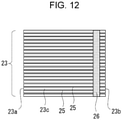
- the tobacco rod 2 can be formed by enclosing the tobacco strands 23 coupled to each other via the tobacco coupling member 26, as illustrated in Fig. 12 , by the wrapping paper 22 and forming the tobacco strands 23 into a rod shape.
- the tobacco strands 23 are also coupled to each other integrally via the tobacco coupling member 26 in the tobacco rod 2 in the present embodiment and thus exert the same effects as those in each of the above-described embodiments.
Landscapes
- Cigarettes, Filters, And Manufacturing Of Filters (AREA)
- Manufacture Of Tobacco Products (AREA)
Abstract
Description
- The present invention relates to a heating-type tobacco.
- There is a known heating-type tobacco including a tobacco rod formed by filling the inside of wrapping paper with a tobacco filler containing a tobacco raw material (for example, tobacco shreds, tobacco granules, a reconstituted tobacco material, and the like) and an aerosol-source material (glycerin, propylene glycol, and the like) (refer to, for example, PTL 1). A heating-type tobacco of such a type is a tobacco article of a type that heats a tobacco filler by a heater of a heating device without burning the tobacco filler and delivers an aerosol generated at the tobacco filler to a user. As the heater, heaters having various shapes, such as a blade shape and a rod shape, have been practically used. The heater is inserted for use from the leading end surface of the tobacco rod, and the tobacco rod is thereby attached to the heating device.
-
- Patent document 1:
Japanese Patent No. 5920744 - Patent document 2:
Japanese Patent No. 6000451 - Patent document 3:
Japanese Patent No. 6017546 - Patent document 4:
Japanese Patent Application Publication No. 62-272962 - Here, in a tobacco rod for an existing heating-type tobacco, a tobacco raw material of a tobacco filler is oriented randomly. Thus, it may be difficult to smoothly insert a heater into the tobacco filler when attaching the heating-type tobacco to a heating device. In addition, in formation of a tobacco rod of a heating-type tobacco by using a tobacco filler in which a tobacco raw material is oriented randomly, an aerosol generated as a result of an aerosol-source material being volatilized is easily condensed by being exposed to a low-temperature part of the randomly oriented tobacco raw material and is easily filtered by the tobacco raw material, and the delivery amount of the aerosol into an oral cavity may decrease.
- The inventors of the present application have discovered that it is possible to improve a tobacco rod for a conventional heating-type tobacco by employing a structure in which a large number of long tobacco strands obtained by forming a tobacco raw material into strand shapes are disposed to extend in the longitudinal direction of a tobacco rod.
- However, when a large number of tobacco strands are oriented in the longitudinal direction of a tobacco rod, there is a concern of the tobacco strands being pressed by a heater, when the heater is inserted from the leading end surface of the tobacco rod, into the base end side (for example, the filter side) of the tobacco rod.
- The present invention has been made in consideration of the aforementioned circumstances, and an object of the present invention is to provide a technique that is excellent in terms of the delivery amount of an aerosol, that enables smooth insertion of a heater into a tobacco filler, and that can suppress a tobacco raw material from being pressed by the heater when the heater is inserted into the tobacco filler, in a heating-type tobacco including a tobacco rod that includes the tobacco filler including the tobacco raw material and an aerosol-source material and wrapping paper that wraps the tobacco filler.
- The present invention for solving the aforementioned problems is a heating-type tobacco including a tobacco rod that includes a tobacco filler and wrapping paper that wraps the tobacco filler. The tobacco filler includes a plurality of tobacco strands each of which is formed in a strand shape and is a tobacco raw material containing an aerosol-source material. The plurality of tobacco strands is aligned and disposed to extend in a longitudinal direction of the tobacco rod, and at least some of the tobacco strands are fixed to each other integrally.
- In the heating-type tobacco according to the present invention, a fixed region portion in which at least some of the tobacco strands are fixed to each other integrally may be formed at only a specific portion of the tobacco rod in the longitudinal direction.
- In the heating-type tobacco according to the present invention, the fixed region portion may be formed at a portion on a rear end side of the tobacco rod.
- In the heating-type tobacco according to the present invention, a fixed region portion in which at least some of the tobacco strands are fixed to each other integrally may be formed in the tobacco rod over the entire length of the tobacco rod.
- In the heating-type tobacco according to the present invention, in the fixed region portion, at least some of the tobacco strands may be point-bonded to each other.
- In the heating-type tobacco according to the present invention, in the fixed region portion, a fixing agent that point-bonds at least some of the tobacco strands to each other may be dotted.
- In the heating-type tobacco according to the present invention, the fixing agent may include at least one of carboxymethyl cellulose, polyvinyl alcohol, and ethylene-vinyl acetate copolymer resin.
- In the heating-type tobacco according to the present invention, the fixed region portion may be formed to cover only a portion of a cross-section of the tobacco rod.
- In the heating-type tobacco according to the present invention, the fixed region portion may be formed in only a specific region that is a portion of the cross-section of the tobacco rod, and the specific region may be set in the cross-section of the tobacco rod as a region that includes a heater insertion region into which a heater is inserted when the heating-type tobacco is attached to a heating device.
- In the heating-type tobacco according to the present invention, the fixed region portion may be arranged in a mesh shape or a lattice shape along the cross-section of the tobacco rod.
- In the heating-type tobacco according to the present invention, the fixing agent that fixes at least some of the tobacco strands to each other in the fixed region portion may include at least one of calcium carbonate and sodium silicate.
- In the heating-type tobacco according to the present invention, at least some of the tobacco strands may be coupled to each other via a tobacco coupling member formed by a tobacco raw material.
- In the heating-type tobacco according to the present invention, the tobacco coupling member may couple portions on a rear end side of the tobacco strands to each other.
- In the heating-type tobacco according to the present invention, the tobacco strands of a number that is 50% or more of a total number of the tobacco strands included in the tobacco filler may be fixed to each other integrally. In addition, the tobacco strands of a number that is 70% or more of a total number of the tobacco strands included in the tobacco filler may be fixed to each other integrally. In addition, the tobacco strands of a number that is 90% or more of a total number of the tobacco strands included in the tobacco filler may be fixed to each other integrally.
- The heating-type tobacco may include a mouthpiece portion coaxially coupled to a base end side of the tobacco rod, and the mouthpiece portion may include a cooling portion for cooling a volatile substance emitted from the aerosol-source material.
- In the heating-type tobacco according to the present invention, the mouthpiece portion may further include a support portion that is disposed at a connection end connected to the base end side of the tobacco rod and that is for suppressing the tobacco strands from being pressed into a region on a side of the mouthpiece portion.
- In the heating-type tobacco according to the present invention, the mouthpiece portion may further include a filter portion that is disposed at an inhalation port end side of the mouthpiece portion.
- Note that solutions to problems in the present invention can be employed in combination as far as possible. Advantageous Effects of Invention
- According to the present invention, it is possible to provide a technique that is excellent in terms of the delivery amount of an aerosol, that enables smooth insertion of a heater into a tobacco filler, and that can suppress a tobacco raw material from being pressed by the heater when the heater is inserted into the tobacco filler, in a heating-type tobacco that includes a tobacco rod including the tobacco filler containing the tobacco raw material and an aerosol-source material and wrapping paper that wraps the tobacco filler.
-
- [
Fig. 1] Fig. 1 is a view schematically illustrating an internal structure of a heating-type tobacco according toEmbodiment 1. - [
Fig. 2] Fig. 2 is a view illustrating an internal structure of a tobacco rod according toEmbodiment 1. - [
Fig. 3] Fig. 3 is a perspective view illustrating an example of a tobacco strand. - [
Fig. 4] Fig. 4 is a view for roughly describing an example of a state in which tobacco strands are fixed to each other in a fixed region portion in a tobacco rod according toEmbodiment 1. - [
Fig. 5] Fig. 5 is a general configuration view of a heating device to which a heating-type tobacco is to be applied. - [
Fig. 6] Fig. 6 is a view describing a tobacco rod of a heating-type tobacco in Embodiment 2. - [
Fig. 7] Fig. 7 is a view describing a fixed region portion of a tobacco rod according to a modification ofEmbodiment 2. - [
Fig. 8] Fig. 8 is a view describing a tobacco rod of a heating-type tobacco in Embodiment 3. - [
Fig. 9] Fig. 9 is a view illustrating a relationship between a tobacco rod and an electric heater in a state in which the tobacco rod of a heating-type tobacco according to Embodiment 3 is attached to a heating device. - [
Fig. 10] Fig. 10 is a view describing a relationship between a fixed-portion formation region and a heater insertion region in a cross-section of a tobacco rod according toEmbodiment 3. - [
Fig. 11] Fig. 11 is a view describing a tobacco rod of a heating-type tobacco in Embodiment 4. - [
Fig. 12] Fig. 12 is a view illustrating a state in which tobacco strands are coupled to each other via a tobacco coupling member. - Here, embodiments of a heating-type tobacco according to the present invention will be described on the basis of the drawings. Dimensions, materials, and shapes of components described in the present embodiments, the relative arrangement thereof, and the like are not intended to limit the technical scope of the invention thereto only unless specific description is provided in particular.
-
Fig. 1 is a view schematically illustrating an internal structure of a heating-type tobacco 1 according toEmbodiment 1. The heating-type tobacco 1 is a tobacco article of a type that heats a tobacco filler without burning the tobacco filler and delivers an aerosol generated at the tobacco filler to a user.Fig. 2 is a view illustrating an internal structure of a tobacco rod according toEmbodiment 1. - The heating-
type tobacco 1 includes atobacco rod 2 and amouthpiece portion 3 that are arranged by being aligned coaxially. The heating-type tobacco 1 has aninhalation port end 1a that is inserted by a user into the oral cavity during use, and adistal end 1b at an end portion opposite to theinhalation port end 1a. Themouthpiece portion 3 includes asupport portion 4, a coolingportion 5, and afilter portion 6 that are arranged by being aligned coaxially. These members are disposed in the order from the distal end side of themouthpiece portion 3. Thesupport portion 4, the coolingportion 5, and thefilter portion 6 of themouthpiece portion 3 are wrapped integrally by wrappingpaper 7. Further, thetobacco rod 2 and themouthpiece portion 3 are coupled integrally by being wrapped bytip paper 8. The sign CL1 inFig. 1 indicates the center axis of the heating-type tobacco 1. Thetobacco rod 2 and themouthpiece portion 3 of the heating-type tobacco 1 are disposed coaxially, and the center axis CL1 can be considered as the center axis of thetobacco rod 2 and themouthpiece portion 3. Thesign 2a inFig. 1 indicates a front end surface of thetobacco rod 2. The sign 2c indicates a rear end surface of thetobacco rod 2. - During the use of the heating-
type tobacco 1, air is inhaled by a user from thedistal end 1b to theinhalation port end 1a through the heating-type tobacco 1. Thedistal end 1b of the heating-type tobacco 1 can be regarded as the distal end or the upstream end of thetobacco rod 2. Theinhalation port end 1a of the heating-type tobacco 1 can be regarded as the rear end or the downstream end of thefilter portion 6. - The
tobacco rod 2 is disposed at thedistal end 1b of the heating-type tobacco 1. Thetobacco rod 2 is a bar-shaped member wrapped by wrappingpaper 22 such that a side surface of atobacco filler 21 that contains a tobacco raw material and an aerosol-source material is covered. In the present embodiment, thetobacco filler 21 includes a plurality oftobacco strands 23 each of which is formed in a strand shape and is a tobacco raw material containing an aerosol-source material. Thetobacco strands 23 are, for example, a tobacco raw material that is formed into a sheet-shaped tobacco sheet and shredded into strand shapes. In the present description, "strand shape" denotes a long elongated shape, compared with a cross-section, extending in the longitudinal direction orthogonal to the direction of the cross-section and includes, for example, a strip shape, a string shape, a bar shape, and the like. The aerosol-source material contained in eachtobacco strand 23 of thetobacco filler 21 is a substance that generates an aerosol when a volatile substance volatilized and emitted is cooled. The type of the aerosol-source material is not particularly limited, and substances extracted from various natural products can be selected, as appropriate, in accordance with intended uses. Examples of the aerosol-source material are glycerin, propylene glycol, triacetin, 1,3-butanediol, a mixture thereof, and the like. Thetobacco strands 23 of thetobacco filler 21 may contain a flavor. The type of the flavor is not particularly limited. -
Fig. 3 is a perspective view illustrating an example of thetobacco strands 23 according toEmbodiment 1. In the example illustrated inFig. 3 , thetobacco strand 23 has a strip shape (for example, a thin rectangular parallelepiped shape). At thetobacco filler 21 of thetobacco rod 2 in the present embodiment, a large number (plurality) oftobacco strands 23 are oriented and disposed. Thetobacco strands 23 are aligned to extend in the longitudinal direction (the direction of the center axis CL1) of thetobacco rod 2. Thesign 23a inFig. 3 indicates a front end surface of thetobacco strand 23, and thesign 23b indicates a rear end surface of thetobacco strand 23. Thefront end surface 23a of thetobacco strand 23 is an end surface that faces thedistal end 1b of the heating-type tobacco 1. Therear end surface 23b of thetobacco strand 23 is an end surface opposite to thefront end surface 23a in the longitudinal direction (extension direction) of thetobacco strand 23. In the present embodiment, therear end surface 23b of eachtobacco strand 23 is disposed to face the front end surface of thesupport portion 4 disposed at the front end of themouthpiece portion 3. Thesign 23c inFig. 3 indicates a side surface of thetobacco strand 23. Thetobacco strands 23 aligned to extend in the longitudinal direction of thetobacco rod 2 are disposed withrespective side surfaces 23c facing each other. Thesign 25 inFig. 2 indicates aerosol flow paths formed between thetobacco strands 23 in the longitudinal direction (the extension direction of the tobacco strands 23) of thetobacco rod 2. - The
tobacco strands 23 are, for example, a tobacco raw material that is formed into a sheet-shaped tobacco sheet and shredded into strand shapes and may be obtained by shredding a so-called reconstituted tobacco sheet into strand shapes. The reconstituted tobacco sheet may be, for example, a sheet obtained by adding a binding agent, a gelling agent, a crosslinking agent, a flavor, a viscosity modifier, a moisturizing agent, a reinforcement material, and the like as additives to a homogenized tobacco, kneading the homogenized tobacco, forming the homogenized tobacco into a sheet shape by an appropriate method, such as a paper making method (sheet making method), a casting method (slurry method), a rolling method, or an extruding method, and drying the homogenized tobacco. The homogenized tobacco is a tobacco material that is obtained by pulverizing, grinding, and mixing, for example, a leaf tobacco, dried tobacco leaves, tobacco shreds, an expanded tobacco, a regenerated tobacco, and the like. - The
tobacco filler 21 for thetobacco rod 2 in the present embodiment is characterized in that at least some of thetobacco strands 23 are integrally fixed to each other. A form in which thetobacco strands 23 are fixed to each other by a fixing agent will be described here. The fixing agent is not particularly limited as long as being capable of fixing thetobacco strands 23 to each other, and various materials can be employed as the fixing agent. For example, a single substance, such as calcium carbonate, sodium silicate, agar, gelatin, CMC (carboxymethyl cellulose), PVA (polyvinyl alcohol), EVA (ethylene-vinyl acetate copolymer resin), pectin, gellan gum, guar gum, Arabic gum, xanthan gum, cornstarch, sodium alginate, polyurethane, polyamide, a hydroxyl-containing compound, dextrin or a dextrin derivative, hydroxypropyl cellulose, hydroxyethyl cellulose, hydroxypropyl methylcellulose, methylcellulose, glucomannan, collagen, inulin, soy protein, whey protein, casein, wheat gluten, carrageenin, alginate, propylene glycol alginate, pullulan, curdlan, ceratonia siliqua gum, tara gum, tragacanth gum, zein, psyllium seeds, chitin, chitosan, acacia gum, polyvinylpyrrolidone, polyethylene oxide, or the like, or a mixture of such single substances is used as the fixing agent. Here, from the point of view of ease of handling of the fixing agent, difficulty in attaching thetobacco filler 21 to the electric heater when the electric heater is inserted, heat resistance, and a smoke flavor and the like during heating by the heater, an aqueous solution containing calcium carbonate or an aqueous solution containing sodium silicate (soluble glass) is preferably employed as the fixing agent. The fixing agent may be an aqueous solution containing calcium carbonate and sodium silicate. From the point of view of the strength of the adhesive force and heat resistance in addition to the point of view of the smoke flavor and the like during heating by the heater, it is preferable to use as the fixing agent an aqueous solution that contains at least one of CMC (carboxymethyl cellulose), PVA (polyvinyl alcohol), and EVA (ethylene-vinyl acetate copolymer resin). - In this example, the fixing agent is added to the entirety of the
tobacco filler 21 of thetobacco rod 2. Consequently, all of thetobacco strands 23 included in thetobacco filler 21 are integrated with each other. The region surrounded by the chain line indicated by thesign 24 inFig. 2 is a fixed region portion. The fixedregion portion 24 is a region in which thetobacco strands 23 are fixed to each other integrally via the fixing agent or the like. In the example illustrated inFig. 2 , the fixedregion portion 24 is formed at almost the entirety of the tobacco rod 2 (tobacco filler 21). However, as described later, only some of thetobacco strands 23 included in thetobacco filler 21 may be fixed to each other integrally by the fixing agent. -
Fig. 4 is a view for roughly describing an example of a state in which thetobacco strands 23 are fixed to each other in the fixedregion portion 24 in the tobacco rod 2 (tobacco filler 21) according toEmbodiment 1. In the example illustrated inFig. 4 , thetobacco strands 23 are fixed (bonded) to each other via a fixingagent 27. In the form illustrated inFig. 4 , the fixingagent 27 is a fixing agent sprayed onto thetobacco strands 23 in the production process of thetobacco rod 2 and cured. In the form illustrated inFig. 4 , the fixingagent 27 is dotted in a region of the tobacco rod 2 (tobacco filler 21) and point-bonds (also referred to as "point-fix") onetobacco strand 23 to theother tobacco strand 23. The point bonding (point-fixing) referred here includes not only a form in which onetobacco strand 23 is bonded (fixed) in a dot manner to the othersingle tobacco strand 23 but also a form in which onetobacco strand 23 is bonded (fixed) to a plurality of theother tobacco strands 23 collectively. Onetobacco strand 23 and theother tobacco strands 23 may be bonded (fixed) to each other at a plurality of portions of thetobacco rod 2 in the longitudinal direction by the fixingagent 27. - In the present embodiment, the fixing
agent 27 can point-bond thetobacco strands 23 to each other in a dot manner due to the fixingagent 27 being dotted in the fixedregion portion 24 of the tobacco rod 2 (tobacco filler 21). It is possible by thus point-bonding thetobacco strands 23 to each other to integrally fix thetobacco strands 23 to each other while forming (remaining as gap portions) theaerosol flow paths 25 between thetobacco strands 23 aligned in the tobacco rod 2 (tobacco filler 21). When a form in which the fixingagent 27 is thus dotted in the fixedregion portion 24 is employed, it is particularly suitable to use CMC (carboxymethyl cellulose), PVA (polyvinyl alcohol), EVA (ethylene-vinyl acetate copolymer resin), or the like as the fixingagent 27. These fixing agents have very high adhesive forces and thus can bond thetobacco strands 23 to each other easily in a dot manner. - From the point of view of ensuring a larger number of gap spaces that are usable as the
aerosol flow paths 25 in the tobacco rod 2 (tobacco filler 21), it is preferable to dot the fixingagent 27 by, for example, spraying the fixingagent 27 onto the fixedregion portion 24 but is not limited thereto. For example, thetobacco strands 23 may be fixed to each other by adding, to the fixedregion portion 24, the fixingagent 27 that contains calcium carbonate or sodium silicate to the fixedregion portion 24 to thereby form an adhesive layer in the fixedregion portion 24. - Next, the
mouthpiece portion 3 will be described. Thesupport portion 4 is a segment positioned on the front end side of themouthpiece portion 3. Thesupport portion 4 is positioned on the immediate downstream side of thetobacco rod 2 and disposed in a state of being in contact with the rear end of thetobacco rod 2. Thesupport portion 4 may be, for example, a hollow cellulose-acetate pipe body. In other words, thesupport portion 4 may be a columnar cellulose-acetate fiber bundle with a center hole formed at the center of a cross-section of the cellulose-acetate fiber bundle to pass therethrough. As another form, thesupport portion 4 may be a paper filter, a paper pipe, or the like filled with cellroll fibers. A paper pipe having a certain thickness can function effectively as thesupport portion 4. Thesupport portion 4 is a segment for preventing thetobacco filler 21 from being pressed into the downstream side toward the coolingportion 5 in the heating-type tobacco 1 when an electric heater of a heating device to which the heating-type tobacco 1 is applied is inserted into thetobacco rod 2. Thesupport portion 4 also functions as a spacer for spacing thecooling portion 5 of the heating-type tobacco 1 from thetobacco rod 2. - The cooling
portion 5 is positioned on the immediate downstream side of thesupport portion 4 and disposed in contact with the rear end of thesupport portion 4. During the use of the heating-type tobacco 1, a volatile substance emitted from the tobacco rod 2 (tobacco filler 21) flows along the coolingportion 5 toward the downstream side. The volatile substance that has been emitted from the tobacco rod 2 (tobacco filler 21) is cooled at the coolingportion 5 and thereby forms an aerosol that is to be inhaled by a user. In the form illustrated inFig. 1 , the coolingportion 5 is formed of a hollow paper pipe having anair hole 5a through which outside air can be introduced. The coolingportion 5, however, may have noair hole 5a. In addition, the coolingportion 5 may include a heat absorbing agent disposed not to obstruct the flow of the volatile substance and the aerosol. The coolingportion 5 may be formed by, for example, a filter material having a large number of flow paths (through holes) formed in the longitudinal direction (axial direction) of themouthpiece portion 3. - The
filter portion 6 is a segment that is positioned at the rear end of themouthpiece portion 3, that is, on the side of theinhalation port end 1a. Thefilter portion 6 may be positioned on the immediate downstream side of the coolingportion 5 and disposed in a state of being in contact with the rear end of the coolingportion 5. In the form illustrated inFig. 1 , thefilter portion 6 may include, for example, a filter material that is formed by cellulose-acetate fibers formed in a columnar shape. In addition, thefilter portion 6 may be a center hole filter or a paper filter filled with cellulose fibers or may be a paper pipe containing no filtering medium. Thefilter portion 6 may be formed by any of a solid filter material including a filtering medium, a center hole filter, a paper filter, and a paper pipe including no filtering medium or may be formed by combining a plurality of them selectively. -
Fig. 5 is a schematic configuration view of aheating device 100 to which the heating-type tobacco 1 according toEmbodiment 1 is to be applied. Theheating device 100 includes ahousing 102 that is a housing for housing various types of constituent parts. In thehousing 102, anelectric heater 103, a controller (control unit) 104, apower source 105, and the like are housed. Thehousing 102 has ahousing cavity 107 including anopening portion 106 into which thetobacco rod 2 of the heating-type tobacco 1 is to be inserted. Thehousing cavity 107 is a columnar cavity portion and can house thetobacco rod 2. - As illustrated in
Fig. 5 , theelectric heater 103 is provided in thehousing cavity 107. Theelectric heater 103 has a conical shape, vertically projects from a center portion of abottom portion 107a of thehousing cavity 107 toward theopening portion 106 in a vertical manner, and is tapered gradually from abase end portion 103a toward aleading end portion 103b. The center axis of theelectric heater 103 is coaxial with the center axis of thehousing cavity 107. The type of theelectric heater 103 is not particularly limited. As theelectric heater 103, for example, a steel material on which a heating wire (for example, nichrome, iron chrome, iron nickel, and the like) is laid and disposed, or a ceramic heater or the like can be used. - Here, when the heating-
type tobacco 1 is to be used, theelectric heater 103 is fitted or inserted into thetobacco filler 21 from the side of thefront end surface 2a of thetobacco rod 2 of the heating-type tobacco 1, thereby attaching thetobacco rod 2 to thehousing cavity 107 of theheating device 100. In the present embodiment, thetobacco strands 23 of thetobacco filler 21 of thetobacco rod 2 are integrated with each other by the fixing agent. Accordingly, even when the front end surfaces 23a of thetobacco strands 23 are pressed by theelectric heater 103 when theelectric heater 103 is fitted or inserted from the side of thefront end surface 2a of thetobacco rod 2, thetobacco strands 23 that have come into contact with theelectric heater 103 can be suppressed from being pressed into the base end side (for example, the side of thesupport portion 4 of the mouthpiece portion 3) of thetobacco rod 2. That is, it is possible to suppress displacement of some of thetobacco strands 23 of thetobacco rod 2 in the longitudinal direction of thetobacco rod 2 from occurring and thetobacco strands 23 from coming off from therear end surface 2b of thetobacco rod 2 during attachment of thetobacco rod 2 to thehousing cavity 107 of theheating device 100. - In addition, according to the heating-
type tobacco 1 in the present embodiment, thetobacco strands 23 of thetobacco rod 2 are oriented and disposed to extend in the longitudinal direction (the direction of the center axis CL1) of thetobacco rod 2, and thetobacco strands 23 are aligned to extend in the longitudinal direction (the direction of the center axis CL1) of thetobacco rod 2. Therefore, an aerosol that is generated as a result of the aerosol-source material contained in each of thetobacco strands 23 being volatilized when heated by theelectric heater 103 is not easily condensed due to contact with thetobacco strands 23 and is not easily filtered by thetobacco strands 23. Therefore, according to the heating-type tobacco 1 in the present embodiment, it is possible to increase the delivery amount of the aerosol into the oral cavity of a user more than before. - In addition, according to the heating-
type tobacco 1 in the present embodiment, due to thetobacco strands 23 of thetobacco rod 2 being aligned in the longitudinal direction (the direction of the center axis CL1) of thetobacco rod 2, fitting or insertion of theelectric heater 103 from the side of thedistal end 1b of thetobacco rod 2 is easy, compared with when a tobacco raw material is conventionally oriented randomly. Consequently, theelectric heater 103 is easily fitted or inserted into thetobacco rod 2, and it is possible to provide the heating-type tobacco 1 excellent for a user in terms of usability. As described above, in the present embodiment, it is possible to provide the heating-type tobacco 1 that is excellent in terms of the delivery amount of the aerosol, that enables smooth insertion of theelectric heater 103 into thetobacco filler 21, and that can suppress thetobacco strands 23 from being pressed by theelectric heater 103 when theelectric heater 103 is inserted into thetobacco filler 21. - Furthermore, according to the heating-
type tobacco 1 in the present embodiment, it is possible to form theaerosol flow paths 25 extending in the longitudinal direction of thetobacco rod 2 between thetobacco strands 23. It is thus possible to cause the aerosol generated as a result of thetobacco strands 23 being heated by theelectric heater 103 to circulate along theaerosol flow paths 25. As a result, condensation and filtration of the aerosol generated during heating by theelectric heater 103 are further suppressed from occurring easily in thetobacco rod 2. In other words, by smoothly circulating the aerosol through theaerosol flow paths 25 formed between the side surfaces 23c of thetobacco strands 23, it is possible to increase efficiency in the delivery of the aerosol during use. - Regarding the embodiment described with
Fig. 4 , a form in which the fixedregion portion 24 is formed in thetobacco rod 2 over the entire length of thetobacco rod 2 has been described. However, the fixedregion portion 24 may be formed partially only at a specific portion that is a portion of thetobacco rod 2 in the longitudinal direction. For example, the fixedregion portion 24 may be formed at a rear end portion of thetobacco rod 2. That is, respective rear ends of thetobacco strands 23 may be fixed to each other by adding (for example, spraying) the fixingagent 27 onto therear end surface 23b of each of thetobacco strands 23 of thetobacco rod 2. In addition, regarding the embodiment described withFig. 4 , a form in which the fixedregion portion 24 is formed at the entire region of the cross-section of thetobacco rod 2 has been described. However, the fixedregion portion 24 may be formed at only a portion of the cross-section of thetobacco rod 2. - In the aforementioned embodiment, an example in which all of the
tobacco strands 23 included in the tobacco rod 2 (tobacco filler 21) are integrally fixed to each other has been described. However, only some of thetobacco strands 23 included in thetobacco filler 21 may be partially fixed to each other. In this case, from the point of view of obtaining the above-described effects, it is preferable that thetobacco strands 23 of a number that is 50% or more of the total number of thetobacco strands 23 included in the tobacco rod 2 (tobacco filler 21) be fixed to each other integrally. It is more preferable that thetobacco strands 23 of a number that is 70% or more of the total number of thetobacco strands 23 included in the tobacco rod 2 (tobacco filler 21) be fixed to each other integrally. It is particularly preferable that thetobacco strands 23 of a number that is 90% or more of the total number thereof are fixed to each other integrally. - Next, the heating-
type tobacco 1 according toEmbodiment 2 will be described.Fig. 6 is a view describing thetobacco rod 2 of the heating-type tobacco 1 inEmbodiment 2. A large number (plurality) of thetobacco strands 23 included in thetobacco filler 21 are also oriented and disposed in thetobacco rod 2 in the present embodiment. Thetobacco strands 23 are the same as those inEmbodiment 1 in terms of being aligned to extend in the longitudinal direction (the direction of the center axis CL1) of thetobacco rod 2. In the following description, the same components as those inEmbodiment 1 will not be described in detail by giving the same reference signs as those inEmbodiment 1 thereto. RegardingEmbodiment 1, an example in which the fixing agent is added to the entirety of thetobacco filler 21 of thetobacco rod 2 has been described. RegardingEmbodiment 2, an example in which the fixing agent is added to only a partial region of thetobacco filler 21 of thetobacco rod 2 will be described. - In the
tobacco rod 2 inEmbodiment 2, the fixedregion portion 24 in which at least some of thetobacco strands 23 are fixed to each other integrally is formed at only a portion on the downstream end side of thetobacco rod 2. In the fixedregion portion 24, the rear ends of thetobacco strands 23 aligned to extend in the longitudinal direction (the direction of the center axis CL1) of thetobacco rod 2 are fixed to each other integrally by the fixing agent. For example, the fixedregion portion 24 may be formed such that the entire surface of therear end surface 2b of thetobacco rod 2 is covered by applying the fixing agent, such as an aqueous solution containing calcium carbonate, an aqueous solution (soluble glass) containing sodium silicate, or the like, to the entire surface of therear end surface 2b of thetobacco rod 2. Naturally, as the fixing agent for fixing the rear ends of thetobacco strands 23 to each other to form the fixedregion portion 24, CMC (carboxymethyl cellulose), PVA (polyvinyl alcohol), EVA (ethylene-vinyl acetate copolymer resin), or the like may be used, or the other fixing agents may be used. In the example illustrated inFig. 6 , the fixedregion portion 24 is formed at the rear end portion of thetobacco rod 2 in the longitudinal direction (the direction of the center axis CL1) by fixing the rear ends of thetobacco strands 23 to each other by the fixing agent. The fixedregion portion 24, however, may be formed at the other portion of thetobacco rod 2 in the longitudinal direction. - Even when, as with the
tobacco rod 2 in the present embodiment, the fixedregion portion 24 is formed at only a partial specific portion of thetobacco rod 2 in the longitudinal direction with thetobacco strands 23 fixed to each other integrally in the fixedregion portion 24, the same effects as those of the heating-type tobacco 1 according toEmbodiment 1 are exerted. - In addition, by forming the fixed
region portion 24 at only a partial specific portion of thetobacco rod 2 in the longitudinal direction, as with thetobacco rod 2 in the present embodiment, it is possible to form theaerosol flow paths 25 extending in the longitudinal direction of thetobacco rod 2 between thetobacco strands 23 in the other sections (regions) in which the fixedregion portion 24 is not formed in thetobacco rod 2. That is, by forming the fixedregion portion 24 only at a partial specific portion of thetobacco rod 2 in the longitudinal direction, as in the present embodiment, it becomes easier to ensure the volume of theaerosol flow paths 25 than when the fixedregion portion 24 is formed in thetobacco rod 2 over the entire length of thetobacco rod 2. As a result, it is possible to increase efficiently in the delivery of an aerosol to the oral cavity. - Next, the
tobacco rod 2 according to a modification ofEmbodiment 2 will be described.Fig. 7 is a view describing the fixedregion portion 24 of thetobacco rod 2 according to the modification ofEmbodiment 2. WithFig. 6 , a form in which the fixedregion portion 24 is formed in the entire region of the cross-section of thetobacco rod 2 has been described. In the present modification, the fixedregion portion 24 is formed to cover only a portion of the cross-section of thetobacco rod 2. InFig. 7 , a cross-section of the fixedregion portion 24 is illustrated, and a region that is occupied by the fixedregion portion 24 in the cross-section of thetobacco rod 2 is indicated by lane hatching. As illustrated inFig. 7 , the fixedregion portion 24 is arranged in a mesh shape or a lattice shape along the cross-section of thetobacco rod 2 in the present modification. InFig. 7 , illustration of thetobacco strands 23 disposed on thetobacco rod 2 is omitted. By forming the fixedregion portion 24 to cover only a portion of the cross-section of thetobacco rod 2, as with thetobacco rod 2 according to the present modification, it is possible to suppress theaerosol flow paths 25 of thetobacco rod 2 from easily blocked by the fixedregion portion 24. As a result, it is possible to increase efficiently in the delivery of an aerosol during use. In the present modification, the other shapes may be employed as the cross-sectional shape of the fixedregion portion 24. - Next, the heating-
type tobacco 1 according toEmbodiment 3 will be described.Fig. 8 is a view describing thetobacco rod 2 of the heating-type tobacco 1 inEmbodiment 3. Thetobacco rod 2 of the heating-type tobacco 1 inEmbodiment 3 differs from that inEmbodiment 2, in which the fixedregion portion 24 is formed at the entire surface of the cross-section of thetobacco rod 2, in terms of that the fixedregion portion 24 is formed in a predetermined specific region that is a portion of the cross-section of thetobacco rod 2. Here, in the cross-section of thetobacco rod 2 in the present embodiment, a region in which the fixedregion portion 24 is formed is referred to as a fixed-portion formation region RB. In the present embodiment, the fixed-portion formation region RB in which the fixedregion portion 24 is formed in the cross-section of thetobacco rod 2 is set as a region including a heater insertion region RH into which theelectric heater 103 is inserted when thetobacco rod 2 of the heating-type tobacco 1 is attached to theheating device 100. -
Fig. 9 is a view illustrating a relationship between thetobacco rod 2 and theelectric heater 103 in a state in which thetobacco rod 2 of the heating-type tobacco 1 according toEmbodiment 3 is attached to theheating device 100. InFig. 9 , illustration of components other than theelectric heater 103 of theheating device 100 is omitted. Here, the heater insertion region RH is defined as an occupied area of a portion at which an area occupied in the cross-section of thetobacco rod 2 by theelectric heater 103 when theelectric heater 103 is fitted or inserted into thetobacco rod 2 is largest. Here, theelectric heater 103 of theheating device 100 has a conical shape and has the largest diameter at thebase end portion 103a joined to thebottom portion 107a. Accordingly, in the present embodiment, the heater insertion region RH corresponds to a circular region having a diameter that is substantially equal to the diameter of thebase end portion 103a of theelectric heater 103. -
Fig. 10 is a view describing a relationship between the fixed-portion formation region RB and the heater insertion region RH in the cross-section of thetobacco rod 2 according toEmbodiment 3. Here, the center axis of theelectric heater 103 is coaxial with the center axis of thehousing cavity 107 of theheating device 100. The center axis CL1 of thetobacco rod 2 attached to thehousing cavity 107 is also designed to be coaxial with the center axis of theelectric heater 103. Accordingly, as illustrated inFig. 10 , each of the fixed-portion formation region RB and the heater insertion region RH is formed as a circular region having the center axis CL1 of thetobacco rod 2 as its center. In the present embodiment, a diameter Db of the fixed-portion formation region RB is set to a dimension more than or equal to a diameter Dh of the heater insertion region RH (in the example inFig. 10 , the diameter Db is illustrated as a dimension larger than the diameter Dh). Consequently, it is possible to form the fixed-portion formation region RB such that the fixed-portion formation region RB includes the heater insertion region RH in the cross-section of thetobacco rod 2. - As described above, according to the
tobacco rod 2 in the present embodiment, the fixed-portion formation region RB in the cross-section of thetobacco rod 2 is formed as a region including the heater insertion region RH Therefore, the same effects as those of thetobacco rod 2 according toEmbodiment 2 are exerted without the fixedregion portion 24 being formed at the entirety of the cross-section of thetobacco rod 2. That is, in attachment of thetobacco rod 2 to thehousing cavity 107 of theheating device 100, thetobacco strands 23 of thetobacco rod 2 are suitably suppressed from projecting or coming off from therear end surface 2b of thetobacco rod 2 due to being pressed by theelectric heater 103. The fixing agent for fixing thetobacco strands 23 to each other in the fixedregion portion 24 is not particularly limited, and the above-described various fixing agents can be employed, as appropriate. - Next, the heating-
type tobacco 1 according toEmbodiment 4 will be described.Fig. 11 is a view describing thetobacco rod 2 of the heating-type tobacco 1 inEmbodiment 4. Thetobacco rod 2 of the heating-type tobacco 1 inEmbodiment 4 is characterized in that at least some of thetobacco strands 23 are coupled to each other via atobacco coupling member 26 formed by a tobacco raw material. Here, an example in which all of thetobacco strands 23 included in thetobacco filler 21 of thetobacco rod 2 are coupled to each other via thetobacco coupling member 26 will be described. In the example illustrated inFig. 11 , thetobacco coupling member 26 couples portions on the rear end side of thetobacco strands 23 to each other. -
Fig. 12 is a view illustrating a state in which thetobacco strands 23 are coupled to each other via thetobacco coupling member 26. InFig. 12 , a state before thetobacco strands 23 are wrapped by the wrappingpaper 22 is illustrated. In the example illustrated inFig. 12 , thetobacco strands 23 are coupled to each other by thetobacco coupling member 26. Thetobacco coupling member 26 is a belt-shaped member formed by a tobacco raw material. In the present embodiment, thetobacco coupling member 26 is formed by, for example, shredding a reconstituted tobacco sheet into belt shapes. Thetobacco coupling member 26 may include an aerosol-source material, as with thetobacco strands 23. The method of coupling thetobacco strands 23 by thetobacco coupling member 26 is not particularly limited. For example, thetobacco strands 23 may be coupled to each other via thetobacco coupling member 26 by press fitting thetobacco coupling member 26 to thetobacco strands 23. Thetobacco rod 2 can be formed by enclosing thetobacco strands 23 coupled to each other via thetobacco coupling member 26, as illustrated inFig. 12 , by the wrappingpaper 22 and forming thetobacco strands 23 into a rod shape. - The
tobacco strands 23 are also coupled to each other integrally via thetobacco coupling member 26 in thetobacco rod 2 in the present embodiment and thus exert the same effects as those in each of the above-described embodiments. In addition, according to thetobacco rod 2 in the present embodiment, it is possible to form theaerosol flow paths 25 extending in the longitudinal direction of thetobacco rod 2 between thetobacco strands 23 and thus possible to increase efficiency in the delivery of an aerosol. - Regarding the above-described embodiments, examples in each of which the
electric heater 103 of theheating device 100 has a conical shape have been described. The shape of theelectric heater 103 is, however, not particularly limited. For example, theelectric heater 103 may have a frustoconical shape (truncated cone shape) or may have a blade shape. In addition, theelectric heater 103 may have the other shapes. - Embodiments according to the present invention have been described above. The heating-type tobacco according to the present invention is, however, not limited to those in the embodiments.
-
- 1
- heating-type tobacco
- 2
- tobacco rod
- 3
- filter
- 4
- support portion
- 5
- cooling portion
- 6
- mouthpiece portion
- 21
- tobacco filler
- 22
- wrapping paper
- 23
- tobacco strand
- 24
- fixed portion
- 25
- aerosol flow path
- 26
- tobacco coupling member
Claims (19)
- A heating-type tobacco comprising a tobacco rod that includes a tobacco filler and wrapping paper that wraps the tobacco filler,wherein the tobacco filler includes a plurality of tobacco strands each of which is formed in a strand shape and is a tobacco raw material containing an aerosol-source material, andwherein the plurality of tobacco strands are aligned and disposed to extend in a longitudinal direction of the tobacco rod, and at least some of the tobacco strands are fixed to each other integrally.
- The heating-type tobacco according to claim 1,
wherein a fixed region portion in which at least some of the tobacco strands are fixed to each other integrally is formed at only a specific portion of the tobacco rod in the longitudinal direction. - The heating-type tobacco according to claim 2, wherein the fixed region portion is formed at a portion on a rear end side of the tobacco rod.
- The heating-type tobacco according to claim 1,
wherein a fixed region portion in which at least some of the tobacco strands are fixed to each other integrally is formed in the tobacco rod over the entire length of the tobacco rod. - The heating-type tobacco according to any one of claims 2 to 4, wherein, in the fixed region portion, at least some of the tobacco strands are point-bonded to each other.
- The heating-type tobacco according to claim 5, wherein, in the fixed region portion, a fixing agent that point-bonds at least some of the tobacco strands to each other is dotted.
- The heating-type tobacco according to claim 6, wherein the fixing agent includes at least one of carboxymethyl cellulose, polyvinyl alcohol, and ethylene-vinyl acetate copolymer resin.
- The heating-type tobacco according to any one of claims 2 to 4,
wherein the fixed region portion is formed to cover only a portion of a cross-section of the tobacco rod. - The heating-type tobacco according to claim 8,wherein the fixed region portion is formed in only a specific region that is a portion of the cross-section of the tobacco rod, andwherein the specific region is set in the cross-section of the tobacco rod as a region that includes a heater insertion region into which a heater is inserted when the heating-type tobacco is attached to a heating device.
- The heating-type tobacco according to claim 8 or claim 9, wherein the fixed region portion is arranged in a mesh shape or a lattice shape along the cross-section of the tobacco rod.
- The heating-type tobacco according to claim 2, 3, 8, or 9, wherein a fixing agent that fixes at least some of the tobacco strands to each other in the fixed region portion includes at least one of calcium carbonate and sodium silicate.
- The heating-type tobacco according to claim 1,
wherein at least some of the tobacco strands are coupled to each other via a tobacco coupling member formed by a tobacco raw material. - The heating-type tobacco according to claim 12,
wherein the tobacco coupling member couples portions on a rear end side of the tobacco strands to each other. - The heating-type tobacco according to any one of claims 1 to 13, wherein the tobacco strands of a number that is 50% or more of a total number of the tobacco strands included in the tobacco filler are fixed to each other integrally.
- The heating-type tobacco according to any one of claims 1 to 13, wherein the tobacco strands of a number that is 70% or more of a total number of the tobacco strands included in the tobacco filler are fixed to each other integrally.
- The heating-type tobacco according to any one of claims 1 to 13, wherein the tobacco strands of a number that is 90% or more of a total number of the tobacco strands included in the tobacco filler are fixed to each other integrally.
- The heating-type tobacco according to any one of claims 1 to 16,wherein the heating-type tobacco includes a mouthpiece portion that is coaxially coupled to a base end side of the tobacco rod, andwherein the mouthpiece portion includes a cooling portion for cooling a volatile substance emitted from the aerosol-source material.
- The heating-type tobacco according to claim 17,
wherein the mouthpiece portion further includes a support portion that is disposed at a connection end connected to the base end side of the tobacco rod and that is for suppressing the tobacco strands from being pressed into a region on a side of the mouthpiece portion. - The heating-type tobacco according to claim 17 or claim 18,
wherein the mouthpiece portion further includes a filter portion that is disposed at an inhalation port end side of the mouthpiece portion.
Applications Claiming Priority (1)
| Application Number | Priority Date | Filing Date | Title |
|---|---|---|---|
| PCT/JP2019/013707 WO2020194689A1 (en) | 2019-03-28 | 2019-03-28 | Heating-type tobacco |
Publications (2)
| Publication Number | Publication Date |
|---|---|
| EP3949770A1 true EP3949770A1 (en) | 2022-02-09 |
| EP3949770A4 EP3949770A4 (en) | 2022-11-16 |
Family
ID=72611253
Family Applications (1)
| Application Number | Title | Priority Date | Filing Date |
|---|---|---|---|
| EP19920788.7A Withdrawn EP3949770A4 (en) | 2019-03-28 | 2019-03-28 | Heating-type tobacco |
Country Status (3)
| Country | Link |
|---|---|
| EP (1) | EP3949770A4 (en) |
| JP (1) | JP7182691B2 (en) |
| WO (1) | WO2020194689A1 (en) |
Cited By (1)
| Publication number | Priority date | Publication date | Assignee | Title |
|---|---|---|---|---|
| US20220030936A1 (en) * | 2019-04-18 | 2022-02-03 | Japan Tobacco Inc. | Heated tobacco product |
Families Citing this family (5)
| Publication number | Priority date | Publication date | Assignee | Title |
|---|---|---|---|---|
| KR102682158B1 (en) * | 2021-04-07 | 2024-07-04 | 주식회사 케이티앤지 | Aerosol generating article and aerosol generating device receving the same |
| KR20240016986A (en) * | 2021-06-18 | 2024-02-06 | 니코벤처스 트레이딩 리미티드 | Articles for use in non-flammable aerosol delivery systems |
| WO2023112267A1 (en) * | 2021-12-16 | 2023-06-22 | 日本たばこ産業株式会社 | Non-combustion heated stick |
| WO2023166595A1 (en) * | 2022-03-02 | 2023-09-07 | 日本たばこ産業株式会社 | Tobacco compact comprising binder |
| WO2023166597A1 (en) * | 2022-03-02 | 2023-09-07 | 日本たばこ産業株式会社 | Tobacco compact comprising binder |
Family Cites Families (12)
| Publication number | Priority date | Publication date | Assignee | Title |
|---|---|---|---|---|
| GB1512632A (en) | 1974-03-08 | 1978-06-01 | British Steel Corp | Grain-oriented steel |
| DE2849061C2 (en) | 1977-11-17 | 1986-09-25 | Hollingsworth (U.K.) Ltd., Accrington, Lancashire | Method for stopping an OE rotor spinning machine and an OE rotor spinning machine |
| JPS6017546B2 (en) | 1982-01-14 | 1985-05-04 | 航空宇宙技術研究所長 | How to extinguish a fuel tank fire |
| US4889143A (en) | 1986-05-14 | 1989-12-26 | R. J. Reynolds Tobacco Company | Cigarette rods and filters containing strands provided from sheet-like materials |
| CN104039179B (en) * | 2012-01-09 | 2018-01-26 | 菲利普莫里斯生产公司 | Smoking articles with a dual function cap |
| CN116649630A (en) * | 2014-05-21 | 2023-08-29 | 菲利普莫里斯生产公司 | Aerosol-generating articles with internal receptors |
| WO2017137857A1 (en) | 2016-02-09 | 2017-08-17 | Philip Morris Products S.A. | Smoking article with hydrophobic wrapper and reduced tobacco loose ends |
| US11717018B2 (en) * | 2016-02-24 | 2023-08-08 | R.J. Reynolds Tobacco Company | Smoking article comprising aerogel |
| CA3025060A1 (en) * | 2016-05-25 | 2017-11-30 | Philip Morris Products S.A. | Aerosol-generating article comprising a piston and aerosol-generating device |
| PL3562332T3 (en) * | 2016-12-29 | 2022-10-31 | Philip Morris Products S.A. | Method and apparatus for the production of a component of an aerosol generating article |
| JP3212228U (en) * | 2017-06-16 | 2017-08-31 | 株式会社 東亜産業 | Electronic cigarette cartridge using tobacco plant or non-tobacco plant and supporting member thereof |
| CN107536100B (en) * | 2017-09-26 | 2022-12-30 | 南通烟滤嘴有限责任公司 | Heating non-combustion cigarette with cavity type container section |
-
2019
- 2019-03-28 WO PCT/JP2019/013707 patent/WO2020194689A1/en not_active Ceased
- 2019-03-28 EP EP19920788.7A patent/EP3949770A4/en not_active Withdrawn
- 2019-03-28 JP JP2021508619A patent/JP7182691B2/en not_active Expired - Fee Related
Cited By (1)
| Publication number | Priority date | Publication date | Assignee | Title |
|---|---|---|---|---|
| US20220030936A1 (en) * | 2019-04-18 | 2022-02-03 | Japan Tobacco Inc. | Heated tobacco product |
Also Published As
| Publication number | Publication date |
|---|---|
| WO2020194689A1 (en) | 2020-10-01 |
| JP7182691B2 (en) | 2022-12-02 |
| JPWO2020194689A1 (en) | 2021-11-04 |
| EP3949770A4 (en) | 2022-11-16 |
Similar Documents
| Publication | Publication Date | Title |
|---|---|---|
| JP7182691B2 (en) | heated cigarette | |
| KR20210151197A (en) | heated tobacco | |
| KR102761669B1 (en) | Heated tobacco, heated tobacco product, method for manufacturing tobacco rod in heated tobacco and manufacturing device | |
| JP7012902B2 (en) | Heat-not-burn tobacco | |
| EP3811793B1 (en) | Article for generating aerosol, and method for manufacturing article for generating aerosol | |
| CN112055545B (en) | Cigarette and method of making same | |
| CN107690288A (en) | Aerosol-generating articles and methods for making aerosol-generating articles | |
| TR201910990T4 (en) | Pilag space pilage type filter with sweetener bead. | |
| US20230284677A1 (en) | Consumable for an aerosol provision system | |
| CN109090682A (en) | The heat conducting bar in article is generated used in aerosol | |
| CN104754964A (en) | Smoking article for use with an internal heating element | |
| JP2015516811A (en) | How to make a smoking article | |
| RS54957B1 (en) | ELECTRIC DRIVE AEROSOL MANUFACTURING SYSTEM | |
| CN110192668A (en) | It is a kind of to heat cigarette of not burning | |
| KR102961438B1 (en) | Aerosol generating article containing a mouse terminal cooling element | |
| EP4331395A1 (en) | Non-combustion heating-type tobacco and electrically-heated tobacco product | |
| TW202034797A (en) | Heating type cigarette | |
| CN117295417A (en) | Smoking systems, device kits, consumables, combinations, and methods of achieving a sense of end-arrival and end-arrival anticipation | |
| JP7464574B2 (en) | Heated tobacco products | |
| KR20250114363A (en) | Flavor-absorbing items | |
| CN115721043A (en) | Hollow filter stick loaded with functional parts and preparation device and method thereof | |
| TW202038763A (en) | Heating type cigarette | |
| RU2782802C1 (en) | Heated tobacco article (variants) | |
| JP2023054241A (en) | heated cigarette | |
| WO2025065762A1 (en) | Aerosol generating product applicable to heaters having different lengths |
Legal Events
| Date | Code | Title | Description |
|---|---|---|---|
| STAA | Information on the status of an ep patent application or granted ep patent |
Free format text: STATUS: THE INTERNATIONAL PUBLICATION HAS BEEN MADE |
|
| PUAI | Public reference made under article 153(3) epc to a published international application that has entered the european phase |
Free format text: ORIGINAL CODE: 0009012 |
|
| STAA | Information on the status of an ep patent application or granted ep patent |
Free format text: STATUS: REQUEST FOR EXAMINATION WAS MADE |
|
| 17P | Request for examination filed |
Effective date: 20211026 |
|
| AK | Designated contracting states |
Kind code of ref document: A1 Designated state(s): AL AT BE BG CH CY CZ DE DK EE ES FI FR GB GR HR HU IE IS IT LI LT LU LV MC MK MT NL NO PL PT RO RS SE SI SK SM TR |
|
| DAV | Request for validation of the european patent (deleted) | ||
| DAX | Request for extension of the european patent (deleted) | ||
| REG | Reference to a national code |
Ref country code: DE Ref legal event code: R079 Free format text: PREVIOUS MAIN CLASS: A24F0047000000 Ipc: A24D0001200000 |
|
| A4 | Supplementary search report drawn up and despatched |
Effective date: 20221017 |
|
| RIC1 | Information provided on ipc code assigned before grant |
Ipc: A24D 1/20 20200101AFI20221011BHEP |
|
| STAA | Information on the status of an ep patent application or granted ep patent |
Free format text: STATUS: THE APPLICATION HAS BEEN WITHDRAWN |
|
| 18W | Application withdrawn |
Effective date: 20240108 |