EP3948902B1 - Hochtemperatur-supraleiterkabel - Google Patents
Hochtemperatur-supraleiterkabel Download PDFInfo
- Publication number
- EP3948902B1 EP3948902B1 EP20713819.9A EP20713819A EP3948902B1 EP 3948902 B1 EP3948902 B1 EP 3948902B1 EP 20713819 A EP20713819 A EP 20713819A EP 3948902 B1 EP3948902 B1 EP 3948902B1
- Authority
- EP
- European Patent Office
- Prior art keywords
- hts
- tapes
- shunt
- tape
- cable
- Prior art date
- Legal status (The legal status is an assumption and is not a legal conclusion. Google has not performed a legal analysis and makes no representation as to the accuracy of the status listed.)
- Active
Links
Images




Classifications
-
- G—PHYSICS
- G21—NUCLEAR PHYSICS; NUCLEAR ENGINEERING
- G21B—FUSION REACTORS
- G21B1/00—Thermonuclear fusion reactors
- G21B1/05—Thermonuclear fusion reactors with magnetic or electric plasma confinement
-
- G—PHYSICS
- G21—NUCLEAR PHYSICS; NUCLEAR ENGINEERING
- G21B—FUSION REACTORS
- G21B1/00—Thermonuclear fusion reactors
- G21B1/05—Thermonuclear fusion reactors with magnetic or electric plasma confinement
- G21B1/057—Tokamaks
-
- H—ELECTRICITY
- H01—ELECTRIC ELEMENTS
- H01B—CABLES; CONDUCTORS; INSULATORS; SELECTION OF MATERIALS FOR THEIR CONDUCTIVE, INSULATING OR DIELECTRIC PROPERTIES
- H01B12/00—Superconductive or hyperconductive conductors, cables, or transmission lines
- H01B12/02—Superconductive or hyperconductive conductors, cables, or transmission lines characterised by their form
- H01B12/06—Films or wires on bases or cores
-
- H—ELECTRICITY
- H01—ELECTRIC ELEMENTS
- H01F—MAGNETS; INDUCTANCES; TRANSFORMERS; SELECTION OF MATERIALS FOR THEIR MAGNETIC PROPERTIES
- H01F6/00—Superconducting magnets; Superconducting coils
- H01F6/06—Coils, e.g. winding, insulating, terminating or casing arrangements therefor
-
- Y—GENERAL TAGGING OF NEW TECHNOLOGICAL DEVELOPMENTS; GENERAL TAGGING OF CROSS-SECTIONAL TECHNOLOGIES SPANNING OVER SEVERAL SECTIONS OF THE IPC; TECHNICAL SUBJECTS COVERED BY FORMER USPC CROSS-REFERENCE ART COLLECTIONS [XRACs] AND DIGESTS
- Y02—TECHNOLOGIES OR APPLICATIONS FOR MITIGATION OR ADAPTATION AGAINST CLIMATE CHANGE
- Y02E—REDUCTION OF GREENHOUSE GAS [GHG] EMISSIONS, RELATED TO ENERGY GENERATION, TRANSMISSION OR DISTRIBUTION
- Y02E30/00—Energy generation of nuclear origin
- Y02E30/10—Nuclear fusion reactors
-
- Y—GENERAL TAGGING OF NEW TECHNOLOGICAL DEVELOPMENTS; GENERAL TAGGING OF CROSS-SECTIONAL TECHNOLOGIES SPANNING OVER SEVERAL SECTIONS OF THE IPC; TECHNICAL SUBJECTS COVERED BY FORMER USPC CROSS-REFERENCE ART COLLECTIONS [XRACs] AND DIGESTS
- Y02—TECHNOLOGIES OR APPLICATIONS FOR MITIGATION OR ADAPTATION AGAINST CLIMATE CHANGE
- Y02E—REDUCTION OF GREENHOUSE GAS [GHG] EMISSIONS, RELATED TO ENERGY GENERATION, TRANSMISSION OR DISTRIBUTION
- Y02E40/00—Technologies for an efficient electrical power generation, transmission or distribution
- Y02E40/60—Superconducting electric elements or equipment; Power systems integrating superconducting elements or equipment
Definitions
- the present invention relates to cables for carrying electrical current in a coil of a magnet and comprising high temperature superconductor material.
- a nuclear fusion reactor comprising a magnetic plasma confinement system comprising a magnet coil wound with such a cable.
- High temperature superconductors HTS
- low temperature superconductors LTS materials
- BCS theory All low temperature superconductors have a critical temperature (the temperature above which the material cannot be superconducting even in zero magnetic field) below about 30K.
- critical temperature the temperature above which the material cannot be superconducting even in zero magnetic field
- BCS theory The behaviour of HTS material is not described by BCS theory, and such materials may have critical temperatures above about 30K (though it should be noted that it is the physical differences in superconducting operation and composition, rather than the critical temperature, which define HTS and LTS material).
- HTS cuprate superconductors
- cuprate superconductors ceramics based on cuprates (compounds containing a copper oxide group), such as BSCCO, or ReBCO (where Re is a rare earth element, commonly Y or Gd).
- BSCCO cuprate superconductors
- ReBCO where Re is a rare earth element, commonly Y or Gd.
- Other HTS materials include iron pnictides (e.g. FeAs and FeSe) and magnesium diboride (MgB 2 ).
- the substrate 101 provides a mechanical backbone that can be fed through the manufacturing line and permit growth of subsequent layers.
- the buffer stack 102 is required to provide a biaxially textured crystalline template upon which to grow the HTS layer, and prevents chemical diffusion of elements from the substrate to the HTS which damage its superconducting properties.
- the silver layer 104 is required to provide a low resistance interface from the ReBCO to the stabiliser layer, and the stabiliser layer 105 provides an alternative current path in the event that any part of the ReBCO ceases superconducting (enters the "normal" state).
- HTS tapes may be arranged into an HTS cable.
- An HTS cable as referred to herein, comprises one or more HTS tapes, which are typically connected along their length via conductive material (normally copper).
- the HTS tapes may be stacked (i.e. arranged such that the HTS layers are parallel), or they may have some other arrangement of tapes, which may vary along the length of the cable.
- Notable special cases of HTS cables are single HTS tapes, and HTS pairs.
- HTS pairs comprise a pair of HTS tapes, arranged such that the HTS layers are parallel.
- HTS pairs may be type-0 (with the HTS layers facing each other), type-1 (with the HTS layer of one tape facing the substrate of the other), or type-2 (with the substrates facing each other). Cables comprising more than 2 tapes may arrange some or all of the tapes in HTS pairs. Stacked HTS tapes may comprise various arrangements of HTS pairs, most commonly either a stack of type-1 pairs or a stack of type-0 pairs and (or, equivalently, type-2 pairs).
- critical current I c
- the critical current may depend on a number of factors, including the temperature of the superconductor and the magnetic field at the superconductor. In the latter case, both the field magnitude and the orientation of the superconductor crystal axes in the field are important.
- the critical current of all the tapes in the stack will be relatively uniform.
- current will distribute simply between the tapes in the ratio of the termination resistances at the ends of the cable according to Ohm's law.
- the current distribution can be affected by a number of factors, such as, if the local magnetic field varies in magnitude, or in field angle relative to the c-axis of the ReBCO layer, either along the length or across the width of the tapes within the cable. Such variations will occur when the cable is wound into a coil for a magnet.
- the cable making up the coils at the ends of the stack may have variations of I c across the widths of its constituent tapes.
- the transport current will then flow preferentially in those portions of the width of individual tapes where I c is highest.
- the transport current in one or more tapes in the cable may flow mostly along one edge. Therefore the current distribution in the tapes in the cable may depend principally on the shape of the coil.
- Temperature variations along the cable also may have an effect on how the current is distributed within the cable, particularly as it may be difficult to provide the right amount of cooling to all sections and/or layers of the cable.
- I c across a tape or between tapes may lead to current distributions within an HTS cable which for many applications are not optimal.
- differences in I c between different parts of the tape may give rise to screening currents which flow in closed loops within the HTS material.
- the screening currents are produced to "use up" excess critical current such that all points within the HTS carry the critical current (even in the absence of an external voltage or transport current), as required by the superconducting state.
- screening currents may limit the performance of HTS magnets because only the current that enters and leaves each tape, driven by an externally applied voltage generates a significant magnetic field.
- the magnetic fields that are generated by the screening currents are small and fall off quickly with distance from the tape, they may have an adverse effect on magnetic field quality (i.e.: homogeneity and temporal stability). This may be particularly problematic in magnets where the distance from coils to the region where the magnetic field is utilized is small compared to the tape width, e.g.: NMR insert coils or MRI coils, in which the homogeneity of the magnetic field may have to be controlled to better than 0.0001 % (in NMR) and 0.001% (in MRI).
- Roebel cables in which the individual tapes in the stack are cut into a meandering shape and then weaved together.
- Roebel cables have several disadvantages, however:
- WO2015011491 describes an elongate superconductor comprising three or more strands of HTS arranged in parallel with each other and being electrically connected substantially along their entire length so as to allow current to transfer laterally between strands.
- JP2011222346 describes a cable comprising parallel HTS wires connected with each other at connecting sections by two sheet shaped connecting HTS wires the end portions thereof being fixed to the upper and lower surfaces of the parallel HTS wires.
- WO2018078326 describes a cable comprising tape assemblies stacked as a series of type 0 pairs, such that HTS layers of a type 0 pair face each other and the substrate layers of the type 0 pair are separated by the HTS layers.
- a cable for carrying electrical current in a coil of a magnet comprises an HTS transport tape and a shunt assembly comprising two or more HTS shunt tapes arranged side-by-side across a face of the transport tape.
- Each of the transport and shunt tapes comprises a substrate layer and an HTS layer of high temperature superconductor (HTS) material, the layers of the shunt tapes extending parallel to the layers of the transport tape.
- HTS high temperature superconductor
- the cable comprises at least one tape which comprises HTS material which is different from the HTS material of another one of the tapes.
- the HTS layer of one or more of the shunt tapes may be interrupted by a plurality of discontinuities comprising dropouts and/or full or partial breaks in the HTS layer.
- the discontinuities may be staggered between adjacent shunt tapes.
- the discontinuities within each of the one or more shunt tapes may have a regular spacing. The spacing of the discontinuities may differ between the shunt tapes.
- the shunt tapes may comprise HTS material which is different from the HTS material in the transport tape.
- Two or more shunt tapes may comprise different HTS material from each other.
- the HTS and substrate layers of one or more of the shunt tapes may have a different orientation compared to the HTS and substrate layers of the transport tape.
- orientation of the HTS and substrate layers of the shunt tapes may alternate between laterally adjacent shunt tapes.
- the shunt assembly may comprise a first shunt layer comprising the two or more shunt tapes and a second shunt layer comprising two or more further shunt tapes arranged side-by-side across the first shunt layer, the layers of the further shunt tapes extending parallel to the layers of the transport tape.
- Each shunt tape of the first shunt layer may form a type-0 or type-1 or type-2 pair with an adjacent shunt tape of the second shunt layer.
- the stack may further comprise another transport tape adjacent the shunt assembly such that the transport tapes form a stacked pair with the shunt assembly located inside the pair between the two transport tapes.
- the transport tapes may be arranged as a type-0 pair such that the respective HTS layers of the pair face each other and are between the respective substrate layers of the pair.
- the cable comprises: a stacked tape assembly of HTS tapes, each HTS tape comprising a substrate layer and an HTS layer of high temperature superconductor (HTS) material.
- the tape assembly comprises: a transport tape comprising a continuous HTS layer; a shunt assembly comprising one or more shunt tapes, each including a plurality of discontinuities in its HTS layer; and a normally electrically conducting layer between the transport tape and the shunt assembly for allowing electrical current to pass between the transport tape and the shunt assembly.
- the arrangement of discontinuities in the one or more tapes of the shunt assembly is chosen to direct lateral current distribution in the HTS layer of the transport tape.
- the cable for carrying electrical current in a coil of a magnet.
- the cable comprises a continuous transport conductor layer comprising high temperature superconducting material, and a shunt structure comprising high temperature superconducting material with non-superconducting barriers to direct a distribution of current in the shunt structure.
- the distribution of current in the shunt structure may control a distribution of current in the transport conductor layer.
- nuclear fusion reactor comprising a tokamak and a magnetic plasma confinement system comprising the magnet coil.
- the present invention relates to an HTS cable comprising stacked HTS tapes that allows the current distribution across the cable width, and between tapes, to be adjusted to create a more uniform current density.
- This allows HTS magnets to be produced in which the current density is distributed more evenly between tapes and/or which is more uniform across each turn.
- the current distribution across the width of the cable can also be adjusted so that it is deliberately non-uniform, with the intention of making the magnetic field angle to the ab-plane of the ReBCO layer in each tape as close as possible to zero. This maximizes the critical current of the cable.
- the voltage developed across the HTS cable also provides an early warning of degradation of the cable due to damage to the ReBCO layer, such as cracking (which could result from fatigue due to multiple ramp cycles or thermal cycles, for example), or neutron irradiation.
- the HTS cable may comprise two or more "shunt" HTS tapes sandwiched between a "wound" pair of stacked HTS tapes.
- the wound pair is a continuous pair of tapes (usually, although not necessarily, a type-0 pair) which has no intentional breaks or I C dropouts.
- very low but non-negligible resistances are introduced into the shunt HTS tapes at regular intervals.
- Transport current that exceeds the critical current of the wound pair is forced to share into and distribute between the "internal" shunt HTS tapes.
- I C dropouts e.g. regions of lower critical current or regions which, in use, are non-superconducting
- complete cuts at regular intervals along the shunt tapes, and/or by using shunt tapes with different critical current in different parts of the cable.
- Dropouts can be created by, for example, sharply bending or folding the tape, resulting in local strain induced cracking and I C degradation in the ReBCO layer.
- the n-value of the HTS tapes pieces used in the shunt pairs can also be chosen to help achieve a desired current distribution.
- FIG. 2 shows a cross section through an HTS cable 200 comprising a pair of relatively wide "wound” HTS tapes 201A, 201B arranged as a type-0 pair These can also be considered as "transport” tapes. Between the tapes 201A, 201B of the wound pair are four narrower "shunt" HTS tapes 202A-D in a "2 x 2" matrix arrangement, i.e. an arrangement with two rows and two columns. Each of the HTS tapes comprises a ReBCO layer 204 on a substrate layer 206, with both layers being surrounded by copper cladding 208.
- the HTS tapes 202A and 202C are arranged as a type-2 pair, as are the HTS tapes 202B and 202D.
- a stabiliser layer 210 made from a metal such as stainless steel, brass or copper, is also added on an outer face of the stacked HTS tapes.
- the stabiliser layer can be added at any position in the cable or, in some cases, not included at all.
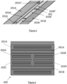
- Figure 3 shows a partially exploded perspective view of some of the layers of HTS cable 200 (tapes 202C-D are omitted for clarity).
- the outermost wound tapes 201A-B are continuous, whilst the shunt tapes 202A-B each have a regular series of breaks 302 along their length.
- the breaks are arranged in the shunt tapes 202A-B so that the breaks in the two tapes do not coincide longitudinally with each other and, in the example shown, have a different spacing.
- the wound HTS tapes 202A, 202 B have no intentional breaks or I c dropouts, so when wound into a coil these tapes present a continuous spiral superconducting path with zero resistance.
- the tapes are grouped into lateral pairs denoted S1 (shunt tapes 202A-B), S2 (shunt tapes 202C-D) and W (tapes 201A-B).
- S1 shunt tapes 202A-B
- S2 shunt tapes 202C-D
- W tapes 201A-B
- the shunt HTS tapes are therefore considers as pairs within each row, rather than within each column, as was the case when discussing the arrangement in terms of type-0 pairs.
- the tapes of shunt pairs S1 and S2 have different critical currents I C,S1 and I C,S2 , from each other and from the tapes of the W pair, which each have a critical current I C,W .
- the W pair When the cable is supplied with an increasing current I 0 , the W pair will carry all the current until I 0 approaches its critical current 2*I C,W . The cable will then then generate enough voltage to shed excess current (I 0 - 2*I c,w ) to the shunt tapes. This excess current will split between the shunt tapes according to the local resistances through the normal metal (i.e. non-HTS material) between the tapes, which is influenced by the dynamic resistance of the tapes and by the spacing of the discontinuities or interruptions (dropouts) along the tapes.
- the normal metal i.e. non-HTS material
- Figure 4 is similar to Figure 2 , except that the HTS cable 400 comprises an additional stabiliser layer 401A located between HTS tape 201A and the S1 shunt pair comprising tapes 202A-B) and an additional stabiliser layer 401B located between HTS tape 202A and the S2 shunt pair comprising tapes 202C-D.
- the additional stabiliser layers are formed from copper although other metals (or alloys) and other conductive materials can also be used.
- One or more such additional stabiliser layers can be included at any position within the HTS cable 400, but preferably between the type-0 pairs formed by the W, S1 or S2 HTS tapes
- HTS cables described herein A further advantage of the HTS cables described herein is that different HTS tapes (i.e. tapes with different HTS material or with different superconducting properties) can be incorporated into a single cable. This allows, for example, HTS tapes from different suppliers to be used to make a single cable, which is particularly important for the construction of large magnet coils for which a single cable supplier may not be able to supply enough HTS tape.
- the HTS cables described herein also may allow for increased critical currents by forcing currents to distribute evenly between the tapes using a combination of (a) choosing the length of the individual HTS tape pieces in each "lane" (e.g. the length of tape pieces 202A, 202A' and 202A") and (b) choosing the tape manufacturer (based on the critical current) in each lane, and/or (c) choosing the width of the shunt HTS tapes 202A-D.
- Figure 5 is similar to Figure 4 , except that two of the HTS shunt tapes 202B and 202D of the HTS cable 500 are arranged as a type-0 pair.
- Figure 6 is similar to Figure 5 , except that the HTS cable 600 comprises two further shunt HTS tapes 602A and 602B arranged as a type-2 pair, such that the orientation of the shunt HTS tapes (i.e. which of the HTS layer and the substrate layer is uppermost) alternates from left to right across the HTS cable 600.
- the shunt HTS tapes are arranged as a 2 x 3 matrix (i.e. there are two rows and 3 columns).
- shunt HTS tapes forming a matrix with any number of row or columns can be used, i.e. an n x m matrix arrangement.
- the width of the transport HTS tapes 201A, 201B is an integer multiple of the width of the shunt HTS tapes, so that an integer number of shunt tapes can be provided across the face of the transport HTS tapes.
- Figure 7 is similar to Figure 3 , except that the HTS cable 600 of Figure 6 is shown.
- the stabiliser layers are omitted for clarity.
- the three (columnar) pairs of shunt HTS tapes are denoted 702A, 702B and 702C.
- the inner pair of shunt HTS tapes 702B has a smaller break spacing than the break spacing of the outer pairs of shunt HTS tapes 702A, 702B. This forces current to flow preferentially in the outer pairs 702A, 702C, as the outer pairs have a higher critical current than the inner pair 702B, since the dynamic resistance for certain ranges of transport currents in the outer pairs 702A, 702C will be lower. This, in turn, causes more current to flow at the edges of the transport tapes 201, 201B than in the middle.
- the current capacity of the cable can be increased because the component of magnetic field perpendicular to each tape is reduced. This is generally beneficial, allowing a coil with the same amount of HTS to generate a higher magnetic field (at a higher transport current), before hotspots (due to local overloading) cause a thermal runaway and consequent quench of the magnet.
- the HTS cable may be wound into a coil using full insulation, partial (e.g. "leaky”) insulation, or no insulation in between the windings.
- partial insulation e.g. "leaky” insulation
- PF poloidal field
- HTS cables such as those described above
- a tokamak features a combination of strong toroidal magnetic field, high plasma current and, usually, a large plasma volume and significant auxiliary heating, to provide hot, stable plasma. This allows tokamaks to generate conditions so that fusion can occur.
- the auxiliary heating (for example via tens of megawatts of neutral beam injection of high energy hydrogen, deuterium or tritium) is necessary to increase the temperature to the sufficiently high values required for nuclear fusion to occur, and/or to maintain the plasma current.
- the magnet coils on a tokamak can be divided into two groups.
- the poloidal field coils are horizontal circular coils wound with their centre lying on the central column of the tokamak, and produce a poloidal field (i.e. one which is substantially parallel to the central column).
- the toroidal field coils are wound vertically through the central column, and around the outside of the plasma chamber (the "return limbs") to produce a toroidal field (i.e. one which is circular around the central column).
- the combination of the poloidal and toroidal fields produces a helical field within the plasma chamber which keeps the plasma confined.
- HTS cables described herein are particularly suitable for use in tokamaks, in particular spherical tokamaks, e.g. to produce either of (or both) the poloidal or toroidal fields.
- FIGS 8 to 11 illustrate a problem with toroidal field (TF) magnets, such as those used in a tokamak, which comprise an arrangement of double pancake coils around a central column.
- TF toroidal field
- Figure 8 shows a cross section through a TF magnet in which double pancake coils 801A-R are arranged uniformly around the centre column 802.
- Each double pancake coil 801A-R is arranged so that its axis lies in the plane of the figure so that when current flows in turn through each of the double pancake coils 801A-R a toroidal magnetic field is produced.
- FIG 9 shows a close-up view of a radial section of one of the double pancake coils 801A-R.
- Each double pancake coil 801A-R is formed from two pancake coils 902A, 902B wound in opposite directions around a common axis (not shown) and stacked face-to-face.
- Each coil 902A, 902B is formed of HTS cable consisting of stacked HTS tapes in a type-0 arrangement, i.e. a "conventional" HTS cable as described in the Background section above.
- Adjacent windings 905, 906 of the HTS cable are separated from one another by a partially insulating layer 907.
- Figure 10 shows the results of a calculation of the magnetic field within one of the (single) pancake coils 902A, 902B.
- the X and Y axes of the figure, show respective radial and axial distances within the coil.
- the contours show the magnetic field magnitude,
- Line 1001 marks the position of an exemplary winding of the coil 902A, 902B.
- the direction of the arrows shown in the figure indicates the deviation of the magnetic field ( B ) vectors from being parallel to line 1001.
- Figure 11 is similar to Figure 10 , except that the results of a calculation of the critical current are shown.
- each tape is split into 12 strips, with critical current for a single strip summed over all shunt tapes in the turn).
- the calculation of the critical current assumes that the current is uniform across the tape. However, this assumption may not always be valid because, in practice, the current is re-distributed across the tapes (i.e. along the X axis) to achieve a uniform ratio of the current to the critical current, i.e. I x I c B x , T , ⁇ x ⁇ constant .
- the calculation of the critical current distribution can therefore be improved using an iterative procedure in which the current distribution, I(x), is re-calculated using the approximate critical current distribution, I c (x) shown in Figure 11 . This process can be repeated iteratively until both current distributions no longer change. The results shown in Figure 11 therefore represent only the first iteration.
- Figure 11 can be understood with reference to the calculated magnetic field shown in Figure 10 .
- the critical current is highest at the inner radius, where the magnetic field is near zero, but rapidly falls at larger radii (X position) and B increases.
- transport current will flow in the tape in proportion to the I c distribution. Therefore, the inhomogeneity of the magnetic field strength and direction within the coil 802A, 802B gives rise to a tendency for current to "hog" the inner edges of the pancake coils.
- a further advantage of the HTS cables described herein involves monitoring I c degradation of the HTS tapes, such as might be caused by neutron damage in a fusion reactor, or fatigue from thermal or magnetic field cycling.
- I c degradation can be provided, which is of great benefit in, for example, large tokamak coils (both PF and TF).
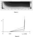
- FIG 12 shows I-V (current-voltage) curves for the HTS cable 200 shown in Figure 2 .
- Each curve is for a different spacing between complete cuts in the shunt HTS tapes. Closer spacing means more resistance and hence a larger gradient (dV/dl).
- the cable 200 Below a current of 2*I C,W , 1201 (the combined critical current of the wound W pair), the cable 200 generates negligible voltage, as it has negligible resistance.
- transport current (I) in the range 2*lc,w (1201) ⁇ I ⁇ 2*I C,W + 4*lc,s (1202), where 4*lc,s is the combined critical current of the two S pairs (S1 and S2), the cable displays a constant resistance, and hence develops a voltage proportional to I.
- I > 2*I C,W + 4*I C,S (1202) the cable shunts excess current into the normal (i.e. non-superconducting) metal stabilizer 210, which will eventually lead to a quench (thermal runaway), as the Joule heating reduces the critical currents of the HTS tapes in the cable.
- the cable is designed to run at a constant transport current somewhere between 1201 and 1202, i.e. between the combined Ic of wound tapes, and the combined I c of the shunt tapes.
- the cable is slightly resistive. It therefore dissipates some power as heat. If the critical current of the cable (either W or S pairs) is degraded, this dissipation will increase slightly, resulting in a rise in temperature until a new thermal equilibrium is reached (wherein the increased heat generation is equal to the increased cooling power available at a raised temperature).
- This temperature rise can be detected by monitoring the temperature of the cable, at many points distributed across the coil.
- a slow rise in temperature therefore provides an indication of a drop in critical current, and therefore can be used a very early warning of a possible quench (thermal runaway) coming at some (indeterminate) time in the future.
- FIG 13 shows a cross section through an HTS cable 1300 that is similar to HTS cable 600 (see Figure 6 ), except that there are now four "transport" HTS tapes 1301A,B and 1304A,B (rather than two as in HTS cable 600).
- the transport HTS tapes are arranged in two layers, the layers being separated from one another by six narrower "shunt" HTS tapes 1302A-C, 1303A-C arranged as for HTS cable 600, i.e. in 2 x 3 matrix.
- the transport HTS tapes 1301A,B and 1304A,B in each layer are arranged side by side, with the HTS layers of each transport HTS tape towards the shunt HTS tapes, thereby creating two type-0 pairs of HTS transport tapes 1301A, 1304A and 1301B, 1304B.
- the middle shunt HTS tapes 1302B, 1303B each span two of the HTS transport tapes.
- the HTS cable 1300 has double the width of the transport HTS tapes 1301A,B, 1304A,B.
- Wider HTS cables can be constructed by adding more type-0 pairs of transport HTS tapes and increasing the number of shunt HTS tapes accordingly, i.e. adding extra columns of shunt HTS tapes or increasing the width of one or more of the shunt HTS tapes 1302A-C, 1303A-C to span the transport HTS tapes.
- Wider HTS cables such as HTS cable 1300, are particularly beneficial for use in TF magnets used in tokamaks because they enable double pancake coils 801A-R of a particular height (size along the axis of the coil) to be constructed from relatively narrow HTS tapes, i.e. fewer coils need to be stacked axially to obtain a given height of double pancake coil. Therefore, fewer joints (i.e. electrical connections) between coils are needed, so manufacturing is more simplified and there are fewer "weak points" for failure. Additionally, the overall resistance of a TF coil constructed from a stack of many narrow pancake coils compared to a TF coil with fewer (e.g. 2) wider pancake coils is more evenly distributed in the latter.
- the wider HTS cables may allow a single TF limb to be constructed from only two coils, which is particularly advantageous because the two pancake coils in each limb 801A can be arranged so that current flows spirally from the inner diameter of one pancake coil to its outer diameter, through a joint between the pancake coils (which is easily accessible as it is on the outer diameter of the pancake coils) and then spirally back from the outer diameter of the other pancake coil to the inner diameter of the other pancake, and then into the next limb 801B through a "limb-limb" joint between the double pancake coils 801A,B.
- the limb-limb joint is located on the inner diameter of the pancake coils and away from the TF centre column 802, which facilitates making, repairing or testing the joint.
- a further advantage to having fewer (e.g. 2) stacked coils is that it reduces the inductance of the pancake coil 801A-R (relative to the inductance of a stack with more coils).
Landscapes
- Engineering & Computer Science (AREA)
- Physics & Mathematics (AREA)
- Plasma & Fusion (AREA)
- General Engineering & Computer Science (AREA)
- High Energy & Nuclear Physics (AREA)
- Power Engineering (AREA)
- Superconductors And Manufacturing Methods Therefor (AREA)
Claims (15)
- Kabel (200, 400, 500, 1300) zum Führen von elektrischem Strom in einer Spule eines Magneten, das Folgendes umfasst:ein HTS-Transportband (201A-B, 1301A, 1304B) undeine Nebenschlussbaugruppe, die zwei oder mehr HTS-Nebenschlussbänder (202A-D, 202A'-B', 202A"-B", 602A-B, 702A-B, 1302A-B, 1303A-C) umfasst, die nebeneinander über eine Fläche des Transportbandes angeordnet sind, undwobei sowohl die Transport- als auch die Nebenschlussbänder eine Substratlage (101) und eine HTS-Lage (103) aus Hochtemperatur-Supraleiter-, HTS-, Material umfassen, wobei sich die Lagen der Nebenschlussbänder parallel zu den Lagen des Transportbandes erstrecken, unddadurch gekennzeichnet, dass das Kabel mindestens ein Band umfasst, das HTS-Material umfasst, das sich von dem HTS-Material eines anderen der Bänder unterscheidet.
- Kabel nach Anspruch 1, wobei die HTS-Lage eines oder mehrerer der Nebenschlussbänder (202A-D, 202A'-B', 202A"-B", 602A-B, 702A-B, 1302A-B, 1303A-C) durch eine Vielzahl von Diskontinuitäten unterbrochen ist, die Aussetzer und/oder vollständige oder teilweise Unterbrechungen in der HTS-Lage (103) umfassen.
- Kabel nach Anspruch 2, wobei die Diskontinuitäten zwischen benachbarten Nebenschlussbändern (202A-D, 202A'-B', 202A"-B", 602A-B, 702A-B, 1302A-B, 1303A-C) versetzt sind.
- Kabel nach Anspruch 2 oder 3, wobei die Diskontinuitäten innerhalb jedes von dem einen oder den mehreren Nebenschlussbändern (202A-D, 202A'-B', 202A"-B", 602A-B, 702A-B, 1302A-B, 1303A-C) einen regelmäßigen Abstand aufweisen.
- Kabel nach Anspruch 4, wobei sich der Abstand der Diskontinuitäten zwischen den Nebenschlussbändern (202A-D, 202A'-B', 202A"-B", 602A-B, 702A-B, 1302A-B, 1303A-C) unterscheidet.
- Kabel nach einem der vorhergehenden Ansprüche, wobei die Nebenschlussbänder (202A-D, 202A'-B', 202A"-B", 602A-B, 702A-B, 1302A-B, 1303A-C) HTS-Material umfassen, das sich von dem HTS-Material in dem Transportband (201A-B, 1301A, 1304B) unterscheidet.
- Kabel nach einem der vorhergehenden Ansprüche, wobei zwei oder mehr Nebenschlussbänder (202A-D, 202A'-B', 202A"-B", 602A-B, 702A-B, 1302A-B, 1303A-C) voneinander unterschiedliches HTS-Material umfassen.
- Kabel nach einem der vorhergehenden Ansprüche, wobei die HTS- (103) und die Substrat- (101) Lagen eines oder mehrerer der Nebenschlussbänder (202A-D, 202A'-B', 202A"-B", 602A-B, 702A-B, 1302A-B, 1303A-C), verglichen mit der HTS- und der Substratlage des Transportbandes (201A-B, 1301A, 1304B), eine unterschiedliche Ausrichtung aufweisen.
- Kabel nach Anspruch 8, wobei sich die Ausrichtung der HTS- (103) und der Substrat- (101) Lagen der Nebenschlussbänder (202A-D, 202A'-B', 202A"-B", 602A-B, 702A-B, 1302A-B, 1303A-C) zwischen seitlich benachbarten Nebenschlussbändern abwechselt.
- Kabel nach einem der vorhergehenden Ansprüche, wobei die Nebenschlussbaugruppe eine erste Nebenschlusslage, welche die zwei oder mehr Nebenschlussbänder (202A-D, 202A'-B', 202A"-B", 602A-B, 702A-B, 1302A-B, 1303A-C) umfasst, und eine zweite Nebenschlusslage, die zwei oder mehr weitere Nebenschlussbänder umfasst, die nebeneinander über die erste Nebenschlusslage angeordnet sind, umfasst, wobei sich die Lagen der weiteren Nebenschlussbänder parallel zu den Lagen des Transportbandes (201A-B, 1301A, 1304B) erstrecken.
- Kabel nach Anspruch 10, wobei jedes Nebenschlussband (202A-D, 202A'-B', 202A"-B", 602A-B, 702A-B, 1302A-B, 1303A-C) der ersten Nebenschlusslage ein Typ-0- oder Typ-1- oder Typ-2-Paar mit einem benachbarten Nebenschlussband der zweiten Nebenschlusslage bildet, wobei die Nebenschlussbänder ein mit Substrat versehenes Band umfassen und in einem Paar von HTS-Bändern die HTS-Bänder derart angeordnet sind, dass die HTS-Lagen parallel sind, wobei in dem Typ-0-Paar die HTS-Lagen zueinander zeigen, in dem Typ-1-Paar die HTS-Lage des einen Bandes zu dem Substrat des anderen zeigt und in dem Typ-2-Paar die Substrate der HTS-Bänder zueinander zeigen.
- Kabel nach einem der vorhergehenden Ansprüche, wobei der Stapel ferner ein anderes Transportband angrenzend an die Nebenschlussbaugruppe umfasst, so dass die Transportbänder (201A-B, 1301A, 1304B) ein gestapeltes Paar bilden, wobei sich die Nebenschlussbaugruppe innerhalb des Paares zwischen den zwei Transportbändern befindet.
- Kabel nach Anspruch 12, wobei die Transportbänder (201A-B, 1301A, 1304B) als ein Typ-0-Paar angeordnet sind, so dass die jeweiligen HTS-Lagen (103) des Paares zueinander zeigen und sich zwischen den jeweiligen Substratlagen des Paares befinden.
- Magnetspule (801A-R, 902A-B), die mit dem Kabel nach einem der vorhergehenden Ansprüche gewickelt ist.
- Kernfusionsreaktor, umfassend einen Tokamak und ein magnetisches Plasmaeinschließungssystem, das die Magnetspule (801A-R, 902A-B) nach Anspruch 14 umfasst.
Applications Claiming Priority (2)
| Application Number | Priority Date | Filing Date | Title |
|---|---|---|---|
| GBGB1904665.5A GB201904665D0 (en) | 2019-04-03 | 2019-04-03 | High temperature supconductor cable |
| PCT/EP2020/059638 WO2020201540A2 (en) | 2019-04-03 | 2020-04-03 | High temperature superconductor cable |
Publications (2)
| Publication Number | Publication Date |
|---|---|
| EP3948902A2 EP3948902A2 (de) | 2022-02-09 |
| EP3948902B1 true EP3948902B1 (de) | 2024-10-16 |
Family
ID=66442892
Family Applications (1)
| Application Number | Title | Priority Date | Filing Date |
|---|---|---|---|
| EP20713819.9A Active EP3948902B1 (de) | 2019-04-03 | 2020-04-03 | Hochtemperatur-supraleiterkabel |
Country Status (9)
| Country | Link |
|---|---|
| US (1) | US12394540B2 (de) |
| EP (1) | EP3948902B1 (de) |
| JP (1) | JP7507783B2 (de) |
| KR (1) | KR20210148292A (de) |
| CN (1) | CN113646853A (de) |
| AU (1) | AU2020252410A1 (de) |
| CA (1) | CA3135874A1 (de) |
| GB (1) | GB201904665D0 (de) |
| WO (1) | WO2020201540A2 (de) |
Families Citing this family (5)
| Publication number | Priority date | Publication date | Assignee | Title |
|---|---|---|---|---|
| US11887752B2 (en) * | 2020-10-26 | 2024-01-30 | The Texas A&M University System | Blocks-in-conduit cable using high-temperature superconducting tape |
| CN113707389A (zh) * | 2021-07-23 | 2021-11-26 | 华北电力大学 | 一种双极同轴高温超导直流电缆均流的设计方法 |
| EP4258285A1 (de) * | 2022-04-04 | 2023-10-11 | Renaissance Fusion | Modulare magnetische begrenzungsvorrichtung |
| WO2023194227A1 (en) * | 2022-04-04 | 2023-10-12 | Renaissance Fusion | Modular magnetic confinement device |
| WO2025122982A1 (en) * | 2023-12-08 | 2025-06-12 | Type One Energy Group, Inc. | Methods and systems for superconductor quench detection, prevention, or mitigation |
Citations (3)
| Publication number | Priority date | Publication date | Assignee | Title |
|---|---|---|---|---|
| US20050139380A1 (en) * | 2003-12-31 | 2005-06-30 | Superpower, Inc. | Novel superconducting articles, and methods for forming and using same |
| US20140100119A1 (en) * | 2012-10-05 | 2014-04-10 | Bruker Hts Gmbh | Superconducting structure having linked band-segments which are each overlapped by directly sequential additional band-segments |
| GB2510447A (en) * | 2013-09-13 | 2014-08-06 | Tokamak Energy Ltd | Toroidal field coil for use in a fusion reactor |
Family Cites Families (16)
| Publication number | Priority date | Publication date | Assignee | Title |
|---|---|---|---|---|
| US6657533B2 (en) * | 1998-11-25 | 2003-12-02 | American Semiconductor Corporation | Superconducting conductors and their method of manufacture |
| US6864430B2 (en) * | 1999-09-09 | 2005-03-08 | Southwire Company | Superconducting cable having a flexible former |
| WO2001041227A1 (en) * | 1999-12-06 | 2001-06-07 | Topchiashvili M I | High temperature superconductor composite material and method of producing a product from the material |
| US6383989B2 (en) * | 2000-06-21 | 2002-05-07 | The Regents Of The University Of California | Architecture for high critical current superconducting tapes |
| JP2005085612A (ja) | 2003-09-09 | 2005-03-31 | Yokohama Tlo Co Ltd | 超電導テープ導体、超電導テープ導体の製造方法、及び超電導テープ導体を備える装置 |
| DE102004048648B4 (de) * | 2004-10-04 | 2006-08-10 | Siemens Ag | Vorrichtung zur Strombegrenzung vom resistiven Typ mit bandfömigem Hoch-Tc-Supraleiter |
| US20090298697A1 (en) * | 2008-05-28 | 2009-12-03 | Superpower, Inc. | Multifilamentary superconducting articles and methods of forming thereof |
| JP5416924B2 (ja) | 2008-06-18 | 2014-02-12 | 株式会社東芝 | 超電導線材及びその製造方法 |
| DE102009038920A1 (de) | 2009-08-26 | 2011-03-10 | Siemens Aktiengesellschaft | Multifilamentleiter und Verfahren zu dessen Herstellung |
| JP2011222346A (ja) * | 2010-04-12 | 2011-11-04 | Toshiba Corp | 高温超電導導体及びそれを用いた高温超電導コイル |
| US8716188B2 (en) | 2010-09-15 | 2014-05-06 | Superpower, Inc. | Structure to reduce electroplated stabilizer content |
| GB201313392D0 (en) * | 2013-07-26 | 2013-09-11 | Mcdougall Ian L | Conductor for superconducting magnets |
| JP6371395B2 (ja) | 2014-08-12 | 2018-08-08 | 国立研究開発法人理化学研究所 | 高温超伝導多芯テープ線、その製造方法、および製造装置 |
| US10062485B2 (en) * | 2015-02-12 | 2018-08-28 | Massachusetts Institute Of Technology | High-temperature superconducting high-current cables |
| DE102016208225A1 (de) * | 2016-05-12 | 2017-11-16 | Bruker Biospin Gmbh | Magnetanordnung mit Feldformelement zur Reduktion der radialen Feldkomponente im Bereich einer HTS Sektion |
| GB201618334D0 (en) | 2016-10-31 | 2016-12-14 | Tokamak Energy Ltd | Cable design in hts tokamaks |
-
2019
- 2019-04-03 GB GBGB1904665.5A patent/GB201904665D0/en not_active Ceased
-
2020
- 2020-04-03 WO PCT/EP2020/059638 patent/WO2020201540A2/en not_active Ceased
- 2020-04-03 CN CN202080026374.4A patent/CN113646853A/zh active Pending
- 2020-04-03 JP JP2021558749A patent/JP7507783B2/ja active Active
- 2020-04-03 US US17/600,693 patent/US12394540B2/en active Active
- 2020-04-03 EP EP20713819.9A patent/EP3948902B1/de active Active
- 2020-04-03 KR KR1020217035879A patent/KR20210148292A/ko not_active Withdrawn
- 2020-04-03 CA CA3135874A patent/CA3135874A1/en active Pending
- 2020-04-03 AU AU2020252410A patent/AU2020252410A1/en not_active Abandoned
Patent Citations (3)
| Publication number | Priority date | Publication date | Assignee | Title |
|---|---|---|---|---|
| US20050139380A1 (en) * | 2003-12-31 | 2005-06-30 | Superpower, Inc. | Novel superconducting articles, and methods for forming and using same |
| US20140100119A1 (en) * | 2012-10-05 | 2014-04-10 | Bruker Hts Gmbh | Superconducting structure having linked band-segments which are each overlapped by directly sequential additional band-segments |
| GB2510447A (en) * | 2013-09-13 | 2014-08-06 | Tokamak Energy Ltd | Toroidal field coil for use in a fusion reactor |
Also Published As
| Publication number | Publication date |
|---|---|
| CN113646853A (zh) | 2021-11-12 |
| WO2020201540A2 (en) | 2020-10-08 |
| CA3135874A1 (en) | 2020-10-08 |
| GB201904665D0 (en) | 2019-05-15 |
| JP7507783B2 (ja) | 2024-06-28 |
| US20220172863A1 (en) | 2022-06-02 |
| AU2020252410A1 (en) | 2021-10-28 |
| KR20210148292A (ko) | 2021-12-07 |
| US12394540B2 (en) | 2025-08-19 |
| WO2020201540A3 (en) | 2020-11-12 |
| JP2022527526A (ja) | 2022-06-02 |
| EP3948902A2 (de) | 2022-02-09 |
Similar Documents
| Publication | Publication Date | Title |
|---|---|---|
| EP3948902B1 (de) | Hochtemperatur-supraleiterkabel | |
| Uglietti et al. | Non-twisted stacks of coated conductors for magnets: Analysis of inductance and AC losses | |
| EP4115432B1 (de) | Geteiltes supraleitendes kabel | |
| EP3747034B1 (de) | Gewickelte hts-magnetspulen | |
| US20190267171A1 (en) | Cable design in hts tokamaks | |
| GB2578307A (en) | Wound HTS magnet coils | |
| JP7754953B2 (ja) | トカマクプラズマチャンバ用の中心柱 | |
| US4409425A (en) | Cryogenically stabilized superconductor in cable form for large currents and alternating field stresses | |
| WO2021252330A1 (en) | Defect-tolerant superconducting magnets and related systems and methods | |
| WO2024118671A9 (en) | High-temperature superconductor magnets with quench damage resiliency | |
| RU2833594C2 (ru) | Центральная колонна для катушки тороидального поля плазменной камеры токамака | |
| US20240412908A1 (en) | Wound hts magnet coils | |
| WO2024213791A1 (en) | Low loss superconductor electrical cable | |
| Breschi | Status, Advances and Challenges of HTS Conductors for Fusion Magnets | |
| JP2026513995A (ja) | 低損失超伝導体電気ケーブル |
Legal Events
| Date | Code | Title | Description |
|---|---|---|---|
| STAA | Information on the status of an ep patent application or granted ep patent |
Free format text: STATUS: UNKNOWN |
|
| STAA | Information on the status of an ep patent application or granted ep patent |
Free format text: STATUS: THE INTERNATIONAL PUBLICATION HAS BEEN MADE |
|
| PUAI | Public reference made under article 153(3) epc to a published international application that has entered the european phase |
Free format text: ORIGINAL CODE: 0009012 |
|
| STAA | Information on the status of an ep patent application or granted ep patent |
Free format text: STATUS: REQUEST FOR EXAMINATION WAS MADE |
|
| 17P | Request for examination filed |
Effective date: 20211027 |
|
| AK | Designated contracting states |
Kind code of ref document: A2 Designated state(s): AL AT BE BG CH CY CZ DE DK EE ES FI FR GB GR HR HU IE IS IT LI LT LU LV MC MK MT NL NO PL PT RO RS SE SI SK SM TR |
|
| DAV | Request for validation of the european patent (deleted) | ||
| DAX | Request for extension of the european patent (deleted) | ||
| P01 | Opt-out of the competence of the unified patent court (upc) registered |
Effective date: 20230512 |
|
| GRAP | Despatch of communication of intention to grant a patent |
Free format text: ORIGINAL CODE: EPIDOSNIGR1 |
|
| STAA | Information on the status of an ep patent application or granted ep patent |
Free format text: STATUS: GRANT OF PATENT IS INTENDED |
|
| INTG | Intention to grant announced |
Effective date: 20240506 |
|
| RAP3 | Party data changed (applicant data changed or rights of an application transferred) |
Owner name: TOKAMAK ENERGY LTD |
|
| GRAS | Grant fee paid |
Free format text: ORIGINAL CODE: EPIDOSNIGR3 |
|
| GRAA | (expected) grant |
Free format text: ORIGINAL CODE: 0009210 |
|
| STAA | Information on the status of an ep patent application or granted ep patent |
Free format text: STATUS: THE PATENT HAS BEEN GRANTED |
|
| AK | Designated contracting states |
Kind code of ref document: B1 Designated state(s): AL AT BE BG CH CY CZ DE DK EE ES FI FR GB GR HR HU IE IS IT LI LT LU LV MC MK MT NL NO PL PT RO RS SE SI SK SM TR |
|
| REG | Reference to a national code |
Ref country code: GB Ref legal event code: FG4D |
|
| REG | Reference to a national code |
Ref country code: CH Ref legal event code: EP |
|
| REG | Reference to a national code |
Ref country code: IE Ref legal event code: FG4D |
|
| REG | Reference to a national code |
Ref country code: DE Ref legal event code: R096 Ref document number: 602020039526 Country of ref document: DE |
|
| REG | Reference to a national code |
Ref country code: LT Ref legal event code: MG9D |
|
| REG | Reference to a national code |
Ref country code: NL Ref legal event code: MP Effective date: 20241016 |
|
| REG | Reference to a national code |
Ref country code: AT Ref legal event code: MK05 Ref document number: 1733644 Country of ref document: AT Kind code of ref document: T Effective date: 20241016 |
|
| PG25 | Lapsed in a contracting state [announced via postgrant information from national office to epo] |
Ref country code: NL Free format text: LAPSE BECAUSE OF FAILURE TO SUBMIT A TRANSLATION OF THE DESCRIPTION OR TO PAY THE FEE WITHIN THE PRESCRIBED TIME-LIMIT Effective date: 20241016 |
|
| PG25 | Lapsed in a contracting state [announced via postgrant information from national office to epo] |
Ref country code: NL Free format text: LAPSE BECAUSE OF FAILURE TO SUBMIT A TRANSLATION OF THE DESCRIPTION OR TO PAY THE FEE WITHIN THE PRESCRIBED TIME-LIMIT Effective date: 20241016 |
|
| PG25 | Lapsed in a contracting state [announced via postgrant information from national office to epo] |
Ref country code: HR Free format text: LAPSE BECAUSE OF FAILURE TO SUBMIT A TRANSLATION OF THE DESCRIPTION OR TO PAY THE FEE WITHIN THE PRESCRIBED TIME-LIMIT Effective date: 20241016 Ref country code: PT Free format text: LAPSE BECAUSE OF FAILURE TO SUBMIT A TRANSLATION OF THE DESCRIPTION OR TO PAY THE FEE WITHIN THE PRESCRIBED TIME-LIMIT Effective date: 20250217 Ref country code: IS Free format text: LAPSE BECAUSE OF FAILURE TO SUBMIT A TRANSLATION OF THE DESCRIPTION OR TO PAY THE FEE WITHIN THE PRESCRIBED TIME-LIMIT Effective date: 20250216 |
|
| PG25 | Lapsed in a contracting state [announced via postgrant information from national office to epo] |
Ref country code: FI Free format text: LAPSE BECAUSE OF FAILURE TO SUBMIT A TRANSLATION OF THE DESCRIPTION OR TO PAY THE FEE WITHIN THE PRESCRIBED TIME-LIMIT Effective date: 20241016 |
|
| PG25 | Lapsed in a contracting state [announced via postgrant information from national office to epo] |
Ref country code: BG Free format text: LAPSE BECAUSE OF FAILURE TO SUBMIT A TRANSLATION OF THE DESCRIPTION OR TO PAY THE FEE WITHIN THE PRESCRIBED TIME-LIMIT Effective date: 20241016 |
|
| PG25 | Lapsed in a contracting state [announced via postgrant information from national office to epo] |
Ref country code: ES Free format text: LAPSE BECAUSE OF FAILURE TO SUBMIT A TRANSLATION OF THE DESCRIPTION OR TO PAY THE FEE WITHIN THE PRESCRIBED TIME-LIMIT Effective date: 20241016 |
|
| PG25 | Lapsed in a contracting state [announced via postgrant information from national office to epo] |
Ref country code: NO Free format text: LAPSE BECAUSE OF FAILURE TO SUBMIT A TRANSLATION OF THE DESCRIPTION OR TO PAY THE FEE WITHIN THE PRESCRIBED TIME-LIMIT Effective date: 20250116 |
|
| PG25 | Lapsed in a contracting state [announced via postgrant information from national office to epo] |
Ref country code: LV Free format text: LAPSE BECAUSE OF FAILURE TO SUBMIT A TRANSLATION OF THE DESCRIPTION OR TO PAY THE FEE WITHIN THE PRESCRIBED TIME-LIMIT Effective date: 20241016 Ref country code: AT Free format text: LAPSE BECAUSE OF FAILURE TO SUBMIT A TRANSLATION OF THE DESCRIPTION OR TO PAY THE FEE WITHIN THE PRESCRIBED TIME-LIMIT Effective date: 20241016 Ref country code: GR Free format text: LAPSE BECAUSE OF FAILURE TO SUBMIT A TRANSLATION OF THE DESCRIPTION OR TO PAY THE FEE WITHIN THE PRESCRIBED TIME-LIMIT Effective date: 20250117 |
|
| PG25 | Lapsed in a contracting state [announced via postgrant information from national office to epo] |
Ref country code: PL Free format text: LAPSE BECAUSE OF FAILURE TO SUBMIT A TRANSLATION OF THE DESCRIPTION OR TO PAY THE FEE WITHIN THE PRESCRIBED TIME-LIMIT Effective date: 20241016 |
|
| PG25 | Lapsed in a contracting state [announced via postgrant information from national office to epo] |
Ref country code: RS Free format text: LAPSE BECAUSE OF FAILURE TO SUBMIT A TRANSLATION OF THE DESCRIPTION OR TO PAY THE FEE WITHIN THE PRESCRIBED TIME-LIMIT Effective date: 20250116 |
|
| PG25 | Lapsed in a contracting state [announced via postgrant information from national office to epo] |
Ref country code: SM Free format text: LAPSE BECAUSE OF FAILURE TO SUBMIT A TRANSLATION OF THE DESCRIPTION OR TO PAY THE FEE WITHIN THE PRESCRIBED TIME-LIMIT Effective date: 20241016 |
|
| PGFP | Annual fee paid to national office [announced via postgrant information from national office to epo] |
Ref country code: DE Payment date: 20250422 Year of fee payment: 6 |
|
| PG25 | Lapsed in a contracting state [announced via postgrant information from national office to epo] |
Ref country code: DK Free format text: LAPSE BECAUSE OF FAILURE TO SUBMIT A TRANSLATION OF THE DESCRIPTION OR TO PAY THE FEE WITHIN THE PRESCRIBED TIME-LIMIT Effective date: 20241016 |
|
| PGFP | Annual fee paid to national office [announced via postgrant information from national office to epo] |
Ref country code: GB Payment date: 20250423 Year of fee payment: 6 |
|
| PGFP | Annual fee paid to national office [announced via postgrant information from national office to epo] |
Ref country code: IT Payment date: 20250424 Year of fee payment: 6 |
|
| REG | Reference to a national code |
Ref country code: DE Ref legal event code: R097 Ref document number: 602020039526 Country of ref document: DE |
|
| PG25 | Lapsed in a contracting state [announced via postgrant information from national office to epo] |
Ref country code: EE Free format text: LAPSE BECAUSE OF FAILURE TO SUBMIT A TRANSLATION OF THE DESCRIPTION OR TO PAY THE FEE WITHIN THE PRESCRIBED TIME-LIMIT Effective date: 20241016 |
|
| PGFP | Annual fee paid to national office [announced via postgrant information from national office to epo] |
Ref country code: FR Payment date: 20250425 Year of fee payment: 6 |
|
| PG25 | Lapsed in a contracting state [announced via postgrant information from national office to epo] |
Ref country code: RO Free format text: LAPSE BECAUSE OF FAILURE TO SUBMIT A TRANSLATION OF THE DESCRIPTION OR TO PAY THE FEE WITHIN THE PRESCRIBED TIME-LIMIT Effective date: 20241016 |
|
| PG25 | Lapsed in a contracting state [announced via postgrant information from national office to epo] |
Ref country code: SK Free format text: LAPSE BECAUSE OF FAILURE TO SUBMIT A TRANSLATION OF THE DESCRIPTION OR TO PAY THE FEE WITHIN THE PRESCRIBED TIME-LIMIT Effective date: 20241016 |
|
| PG25 | Lapsed in a contracting state [announced via postgrant information from national office to epo] |
Ref country code: CZ Free format text: LAPSE BECAUSE OF FAILURE TO SUBMIT A TRANSLATION OF THE DESCRIPTION OR TO PAY THE FEE WITHIN THE PRESCRIBED TIME-LIMIT Effective date: 20241016 |
|
| PLBE | No opposition filed within time limit |
Free format text: ORIGINAL CODE: 0009261 |
|
| STAA | Information on the status of an ep patent application or granted ep patent |
Free format text: STATUS: NO OPPOSITION FILED WITHIN TIME LIMIT |
|
| PG25 | Lapsed in a contracting state [announced via postgrant information from national office to epo] |
Ref country code: SE Free format text: LAPSE BECAUSE OF FAILURE TO SUBMIT A TRANSLATION OF THE DESCRIPTION OR TO PAY THE FEE WITHIN THE PRESCRIBED TIME-LIMIT Effective date: 20241016 |
|
| 26N | No opposition filed |
Effective date: 20250717 |
|
| REG | Reference to a national code |
Ref country code: CH Ref legal event code: H13 Free format text: ST27 STATUS EVENT CODE: U-0-0-H10-H13 (AS PROVIDED BY THE NATIONAL OFFICE) Effective date: 20251125 |
|
| PG25 | Lapsed in a contracting state [announced via postgrant information from national office to epo] |
Ref country code: LU Free format text: LAPSE BECAUSE OF NON-PAYMENT OF DUE FEES Effective date: 20250403 |
|
| PG25 | Lapsed in a contracting state [announced via postgrant information from national office to epo] |
Ref country code: MC Free format text: LAPSE BECAUSE OF FAILURE TO SUBMIT A TRANSLATION OF THE DESCRIPTION OR TO PAY THE FEE WITHIN THE PRESCRIBED TIME-LIMIT Effective date: 20241016 |
|
| REG | Reference to a national code |
Ref country code: BE Ref legal event code: MM Effective date: 20250430 |
|
| PG25 | Lapsed in a contracting state [announced via postgrant information from national office to epo] |
Ref country code: BE Free format text: LAPSE BECAUSE OF NON-PAYMENT OF DUE FEES Effective date: 20250430 |
|
| PG25 | Lapsed in a contracting state [announced via postgrant information from national office to epo] |
Ref country code: CH Free format text: LAPSE BECAUSE OF NON-PAYMENT OF DUE FEES Effective date: 20250430 |
|
| PG25 | Lapsed in a contracting state [announced via postgrant information from national office to epo] |
Ref country code: IE Free format text: LAPSE BECAUSE OF NON-PAYMENT OF DUE FEES Effective date: 20250403 |