EP3948474B1 - Frequenzdomänenbasierte bestimmung von strömen zur injektion in ein stromnetz - Google Patents
Frequenzdomänenbasierte bestimmung von strömen zur injektion in ein stromnetz Download PDFInfo
- Publication number
- EP3948474B1 EP3948474B1 EP20718821.0A EP20718821A EP3948474B1 EP 3948474 B1 EP3948474 B1 EP 3948474B1 EP 20718821 A EP20718821 A EP 20718821A EP 3948474 B1 EP3948474 B1 EP 3948474B1
- Authority
- EP
- European Patent Office
- Prior art keywords
- data structure
- values
- power
- thévenin
- offset
- Prior art date
- Legal status (The legal status is an assumption and is not a legal conclusion. Google has not performed a legal analysis and makes no representation as to the accuracy of the status listed.)
- Active
Links
Images


Classifications
-
- H—ELECTRICITY
- H02—GENERATION; CONVERSION OR DISTRIBUTION OF ELECTRIC POWER
- H02J—ELECTRIC POWER NETWORKS; CIRCUIT ARRANGEMENTS OR SYSTEMS FOR SUPPLYING OR DISTRIBUTING ELECTRIC POWER; SYSTEMS FOR STORING ELECTRIC ENERGY
- H02J3/00—Circuit arrangements for AC mains or AC distribution networks
-
- H—ELECTRICITY
- H02—GENERATION; CONVERSION OR DISTRIBUTION OF ELECTRIC POWER
- H02J—ELECTRIC POWER NETWORKS; CIRCUIT ARRANGEMENTS OR SYSTEMS FOR SUPPLYING OR DISTRIBUTING ELECTRIC POWER; SYSTEMS FOR STORING ELECTRIC ENERGY
- H02J3/00—Circuit arrangements for AC mains or AC distribution networks
- H02J3/18—Arrangements for adjusting, eliminating or compensating reactive power in networks
-
- H—ELECTRICITY
- H02—GENERATION; CONVERSION OR DISTRIBUTION OF ELECTRIC POWER
- H02J—ELECTRIC POWER NETWORKS; CIRCUIT ARRANGEMENTS OR SYSTEMS FOR SUPPLYING OR DISTRIBUTING ELECTRIC POWER; SYSTEMS FOR STORING ELECTRIC ENERGY
- H02J3/00—Circuit arrangements for AC mains or AC distribution networks
- H02J3/04—Arrangements for connecting networks of the same frequency but supplied from different sources
- H02J3/06—Controlling the transfer of power between connected networks; Controlling load sharing between connected networks
-
- H—ELECTRICITY
- H02—GENERATION; CONVERSION OR DISTRIBUTION OF ELECTRIC POWER
- H02J—ELECTRIC POWER NETWORKS; CIRCUIT ARRANGEMENTS OR SYSTEMS FOR SUPPLYING OR DISTRIBUTING ELECTRIC POWER; SYSTEMS FOR STORING ELECTRIC ENERGY
- H02J3/00—Circuit arrangements for AC mains or AC distribution networks
- H02J3/38—Arrangements for feeding a single network from two or more generators or sources in parallel; Arrangements for feeding already energised networks from additional generators or sources in parallel
-
- H—ELECTRICITY
- H02—GENERATION; CONVERSION OR DISTRIBUTION OF ELECTRIC POWER
- H02J—ELECTRIC POWER NETWORKS; CIRCUIT ARRANGEMENTS OR SYSTEMS FOR SUPPLYING OR DISTRIBUTING ELECTRIC POWER; SYSTEMS FOR STORING ELECTRIC ENERGY
- H02J3/00—Circuit arrangements for AC mains or AC distribution networks
- H02J3/38—Arrangements for feeding a single network from two or more generators or sources in parallel; Arrangements for feeding already energised networks from additional generators or sources in parallel
- H02J3/46—Controlling the sharing of generated power between the generators, sources or networks
-
- H—ELECTRICITY
- H02—GENERATION; CONVERSION OR DISTRIBUTION OF ELECTRIC POWER
- H02J—ELECTRIC POWER NETWORKS; CIRCUIT ARRANGEMENTS OR SYSTEMS FOR SUPPLYING OR DISTRIBUTING ELECTRIC POWER; SYSTEMS FOR STORING ELECTRIC ENERGY
- H02J2103/00—Details of circuit arrangements for mains or AC distribution networks
- H02J2103/30—Simulating, planning, modelling, reliability check or computer assisted design [CAD] of electric power networks
-
- H—ELECTRICITY
- H02—GENERATION; CONVERSION OR DISTRIBUTION OF ELECTRIC POWER
- H02J—ELECTRIC POWER NETWORKS; CIRCUIT ARRANGEMENTS OR SYSTEMS FOR SUPPLYING OR DISTRIBUTING ELECTRIC POWER; SYSTEMS FOR STORING ELECTRIC ENERGY
- H02J2103/00—Details of circuit arrangements for mains or AC distribution networks
- H02J2103/30—Simulating, planning, modelling, reliability check or computer assisted design [CAD] of electric power networks
- H02J2103/35—Grid-level management of power transmission or distribution systems, e.g. load flow analysis or active network management
-
- H—ELECTRICITY
- H02—GENERATION; CONVERSION OR DISTRIBUTION OF ELECTRIC POWER
- H02J—ELECTRIC POWER NETWORKS; CIRCUIT ARRANGEMENTS OR SYSTEMS FOR SUPPLYING OR DISTRIBUTING ELECTRIC POWER; SYSTEMS FOR STORING ELECTRIC ENERGY
- H02J3/00—Circuit arrangements for AC mains or AC distribution networks
- H02J3/007—Arrangements for selectively connecting one or more loads to one or more power sources or power lines
- H02J3/0075—Arrangements for selectively connecting one or more loads to one or more power sources or power lines for providing alternative feeding paths between load and source according to economic or energy efficiency considerations, e.g. economic dispatch
-
- Y—GENERAL TAGGING OF NEW TECHNOLOGICAL DEVELOPMENTS; GENERAL TAGGING OF CROSS-SECTIONAL TECHNOLOGIES SPANNING OVER SEVERAL SECTIONS OF THE IPC; TECHNICAL SUBJECTS COVERED BY FORMER USPC CROSS-REFERENCE ART COLLECTIONS [XRACs] AND DIGESTS
- Y02—TECHNOLOGIES OR APPLICATIONS FOR MITIGATION OR ADAPTATION AGAINST CLIMATE CHANGE
- Y02E—REDUCTION OF GREENHOUSE GAS [GHG] EMISSIONS, RELATED TO ENERGY GENERATION, TRANSMISSION OR DISTRIBUTION
- Y02E60/00—Enabling technologies; Technologies with a potential or indirect contribution to GHG emissions mitigation
-
- Y—GENERAL TAGGING OF NEW TECHNOLOGICAL DEVELOPMENTS; GENERAL TAGGING OF CROSS-SECTIONAL TECHNOLOGIES SPANNING OVER SEVERAL SECTIONS OF THE IPC; TECHNICAL SUBJECTS COVERED BY FORMER USPC CROSS-REFERENCE ART COLLECTIONS [XRACs] AND DIGESTS
- Y04—INFORMATION OR COMMUNICATION TECHNOLOGIES HAVING AN IMPACT ON OTHER TECHNOLOGY AREAS
- Y04S—SYSTEMS INTEGRATING TECHNOLOGIES RELATED TO POWER NETWORK OPERATION, COMMUNICATION OR INFORMATION TECHNOLOGIES FOR IMPROVING THE ELECTRICAL POWER GENERATION, TRANSMISSION, DISTRIBUTION, MANAGEMENT OR USAGE, i.e. SMART GRIDS
- Y04S40/00—Systems for electrical power generation, transmission, distribution or end-user application management characterised by the use of communication or information technologies, or communication or information technology specific aspects supporting them
- Y04S40/20—Information technology specific aspects, e.g. CAD, simulation, modelling, system security
Definitions
- the invention relates to frequency domain-based determination of currents for injection into a power network so as to reduce transmission losses associated with delivery of an amount of power.
- an equivalent Thévenin circuit is derived for the network with respect to a point of common coupling, the equivalent Thévenin circuit having an equivalent voltage, resistance, and reactance in series that vary with time.
- An optimised electric current is determined to inject into or extract from the network so as to minimise losses in the network and to ensure that maximum power from the power source reaches the consumer.
- the Thévenin parameters are calculated, a total Thévenin power is calculated, and the current compensation is calculated based on the Thévenin power and the Thévenin parameters.
- the formulation in GB 2,521,414 B is a time domain one and may only lead to optimal results if the resistances and inductances are not frequency dependent. In order to account for the effect of frequency dependent line impedances (resistance, inductance and capacitance), a formulation in the frequency domain may be required.
- Frequency-domain harmonic analysis methods are disclosed by S Mark Halpin ET AL in "Frequency-Domain Harmonic Analysis Methods", 1 January 1998 . Although there have been efforts to derive a suitable frequency domain formulation, there remains scope for improvement.
- a method comprising: compiling Thévenin parameter data structures for each of a Thévenin voltage, resistance and inductance, wherein each data structure has values for each of one or more lines at each of a predetermined set of frequencies, the values having been obtained at a point of common coupling to a power network having the one or more lines; compiling an offset data structure including offset values, each of which is to be applied to a corresponding value of the Thévenin voltage data structure to output an offset Thévenin voltage data structure, wherein the offset values are calculated to satisfy physical constraints associated with the power network; compiling the offset Thévenin voltage data structure; compiling an optimal point of common coupling power data structure including values having been determined based on a specific amount of total power at the point of common coupling and the offset Thévenin voltage data structure or a derivative thereof; using the optimal point of common coupling power data structure and the offset Thévenin voltage data structure to calculate current components for each line and for each of the pre
- the method may be a computer-implemented method for frequency domain-based determination of currents for injection into a power network.
- method to include determining the offset values, for determining the offset values to be based on a projection of the Thévenin voltage data structure or a weighted Thévenin voltage data structure onto vectors in a solution subspace in which the optimal current components are to reside; for the vectors in the solution subspace to be represented by solution subspace data structures; for a solution subspace data structure to be provided for each of the number of frequencies in the predetermined set of frequencies, and for values of each of the solution subspace data structures to represent vectors which are orthogonal to each other.
- a still further feature provides for the offset values to be calculated to satisfy physical constraints including one or both of Kirchhoff's current law and the requirement that values of the optimal point of common coupling power data structure remain the same before and after injection or extraction of the current components.
- a yet further feature provides for the values of the solution subspace data structures to include the values of the Thévenin resistance and inductances data structure.
- values of the Thévenin parameter data structures to be time variable values in the form of frequency domain-based complex root mean square (CRMS) values.
- CRMS complex root mean square
- the method may be conducted at the point of common coupling by a device, such as a compensator, a converter or an inverter, coupled to the power network.
- a device such as a compensator, a converter or an inverter, coupled to the power network.
- the specific amount of total power at the point of common coupling may be a specific amount of total average power over a predetermined time period.
- a system including a memory for storing computer-readable program code and a processor for executing the computer-readable program code, the system comprising: a Thévenin parameter data structure compiling component for compiling Thévenin parameter data structures for each of a Thévenin voltage, resistance and inductance, wherein each data structure has values for each of one or more lines at each of a predetermined set of frequencies, the values having been obtained at a point of common coupling to a power network having the one or more lines; an offset data structure compiling component for compiling an offset data structure including offset values, each of which is to be applied to a corresponding value of the Thévenin voltage data structure to output an offset Thévenin voltage data structure, wherein the offset values are calculated to satisfy physical constraints associated with the power network; an offset Thévenin voltage data structure compiling component for compiling the offset Thévenin voltage data structure; an optimal point of common coupling power data structure compiling component for compiling
- the system may be for frequency domain-based determination of currents for injection into a power network.
- the system may include a connector configured for electrically connecting to the power network at the point of common coupling, wherein the current injecting/extracting component controls injecting or extracting currents associated with the current components via the connector.
- a computer program product comprising a computer-readable medium having stored computer-readable program code for performing the steps of: compiling Thévenin parameter data structures for each of a Thévenin voltage, resistance and inductance, wherein each data structure has values for each of one or more lines at each of a predetermined set of frequencies, the values having been obtained at a point of common coupling to a power network having the one or more lines; compiling an offset data structure including offset values, each of which is to be applied to a corresponding value of the Thévenin voltage data structure to output an offset Thévenin voltage data structure, wherein the offset values are calculated to satisfy physical constraints associated with the power network; compiling the offset Thévenin voltage data structure; compiling an optimal point of common coupling power data structure including values having been determined based on a specific amount of total power at the point of common coupling and the offset Thévenin voltage data structure or a derivative thereof; using the optimal point of common coupling power data structure and
- computer-readable medium to be a non-transitory computer-readable medium and for the computer-readable program code to be executable by a processing circuit.
- aspects of the present disclosure provide a system and method for determining currents for injection into or extraction from a power network at a point of common coupling.
- the currents are determined to minimise transmission losses.
- the currents that are determined may be so-called 'active currents,' which are generally understood to be those line (or wire) currents that transport power from or to a network with minimal transmission losses.
- Active currents may therefore be defined as those line current components that produce the least associated losses in the network for the specific power being introduced into or drawn from the network at a point of common coupling (PCC), assuming the characteristics of the network remain constant.
- PCC point of common coupling
- Defining active currents as the line current components producing the minimum losses in the network for the specific power to be delivered may allow a rigorous definition of apparent power based on a model independent of assumptions about sinusoidal waveform, voltage and current balance, and frequency-dependent wire resistances.
- aspects of the present disclosure implement a generalized frequency domain approach to the derivation or determination of active currents, which formulation uses Thévenin parameters of a network and utilises a specific reference, or offset, for each and every voltage frequency component. Aspects of the present disclosure may therefore allow for the determination of active currents in the presence of frequency dependent line resistances and inductances.
- aspects of the present disclosure may find application in a wide range of power system situations, including small scale power electronics for photovoltaic distributed power injection into 'smart grids', 'mega grids' with flexible alternating current transmission system (FACTS) devices and large-scale power transformers in the presence of direct current (DC) components.
- Aspects of the present disclosure may find application in a compensator (e.g. static VAR compensator, static synchronous compensator, etc.), inverter (e.g. grid-tied inverter or the like) or other suitable apparatus configured to modify an original set of line currents in such a way that the same amount of power is transported to the network or section of the network, but with minimal possible losses.
- a compensator e.g. static VAR compensator, static synchronous compensator, etc.
- inverter e.g. grid-tied inverter or the like
- suitable apparatus configured to modify an original set of line currents in such a way that the same amount of power is transported to the network or section
- aspects of the present disclosure may further find application in the optimization of the operating cycle of storage batteries (including, e.g., small customer-based and larger utility scale units). This may be achievable by inclusion of subharmonic frequencies (e.g. frequencies being lower than the rated power frequency, which is typically 50 or 60 Hz) and by obtaining voltage and current values over intervals of a longer period of time.
- subharmonic frequencies e.g. frequencies being lower than the rated power frequency, which is typically 50 or 60 Hz
- aspects of the present disclosure may find application in controlling power electronics to transport only the useful (optimal) energy to the grid and supplying locally the components of power for which no net energy is required.
- BESS battery energy storage systems
- the adoption of more appropriate control algorithms using the systems and methods described herein has the potential to reduce total energy losses, consistent with economic cost allocation.
- Other potential applications of the systems and methods described herein include load compensators including static synchronous compensators (STATCOMs), the injection of renewable energy in transmission systems, voltage stability analysis (especially where distortion by geomagnetically induced currents severely compromises conventional approaches), in tariffs and revenue transactions, in power quality assessment, steady state power flow modelling, planning and operation, and the like.
- STATCOMs static synchronous compensators
- FIG. 1 is a schematic diagram which illustrates a system (100) for determining currents for injection into or extraction from a power network (102) according to aspects of the present disclosure.
- the power network may include or be in the form of a load network.
- the power network may be in the form of small networks or micro-grids or large national grids with loads and supplies of many different forms.
- the power network may include storage batteries ranging from small end-user-based units to larger, power utility scale units.
- the power network (102) may include multiple nodes and may constantly evolve as a result of loads and power generation availability changes.
- the system may include a device (104) configured for injection of current into or extraction of current from the power network (102).
- the device (104) may be in the form of a converter or invertor or other suitable apparatus, although other implementations are anticipated.
- the device (104) may include a current compensator system (106) which dynamically determines the optimal current components for injection into or extraction from the power network (102) in order to minimise losses across the power network (102).
- the system (100) and in particular, the device (104) and/or current compensation system (106) described above may implement a method for determining currents for injection (108) into or extraction (110) from the power network.
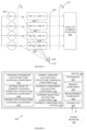
- An exemplary method for determining currents for injection or extraction of power into or from a power network is illustrated in the flow diagram of Figure 2 . Aspects of the method are further described with reference to Figure 3 , which shows an example Thévenin equivalent circuit for an M line power network.
- the method may be conducted at a point of common coupling (302) to a power network (102) having M lines (or wires), where M is greater than or equal to one.
- the method may be conducted by a current compensation system (106) of, or connected to, a device (104) connected to the power network (102) at the point of common coupling.
- the method may thus be a computer-implemented method.
- the operations of the method described below may be conducted based on values that are measured at the point of common coupling over a predetermined time period, T.
- the length of the time period T may vary according to the application. It may be that the length of the time period T at least approximates or is larger than the inverse of the rated power frequency (which may for example be in the region of 50 or 60 Hz). In some applications, however, the time period T may be much larger.
- T of integration e.g. in the order of hours or even days
- K A which may be constant throughout T, may vary accordingly with the time period chosen.
- Vth vector may vary from cycle to cycle as well as its necessary correct reference point.
- the method may include obtaining (202) line voltage and current values for each of the M lines.
- the obtained voltage and current values may be time variable voltage and current values and may be adequately expressed as Fourier components with a finite set of complex root mean square (CRMS) values.
- Obtaining the line voltage and current values may include using suitable fast-Fourier transform (FFT) techniques or Discrete Fourier Analysis (using e.g. a discrete Fourier Transform, DST) of line voltages and currents or the like. These could be obtained by processing measured samples taken at the point of common coupling and meeting the Nyquist criterion of sampling at a frequency at least twice that of the highest frequency components needed to represent the original line voltages and currents.
- FFT fast-Fourier transform
- DST discrete Fourier Transform
- Obtaining (202) line voltages may for example include measuring M voltage signals (represented in the time domain as f(t)) at the point of common coupling side and adequately expressing these signals as a set of H + 1 components (including DC) in the complex RMS Fourier domain. Each line may therefore have H + 1 components expressed as a magnitude and angle (or real and imaginary real number).
- the line currents (304), which may be the same at the point of common coupling side and a Thévenin voltage side, may also be expressed as a magnitude and angle for each of H + 1 components.
- the obtained line voltage and current values may be a condense representation of distorted currents and voltages of each of the M lines over the predetermined time period, T.
- the obtained line voltage and current values may be adequately represented with a predetermined, finite set of H +1 Fourier frequencies (including the DC component).
- the sampled frequencies may include one or more of harmonics, sub-harmonics and sidebands of the power frequency. In the case of sidebands, continuous Fourier analysis may be performed, especially for long periods, say of a day.
- Obtaining line voltage and current values may include obtaining values in the form of complex voltage ( U ) and current ( I S ) components (e.g. values in the form of phasors).
- the obtained line voltages and currents for all frequencies may be compiled (204) into separate data structures ( U and I S respectively), each of which may be in the form of complex vectors constructed from each of the M lines' CRMS values.
- Each of the data structures may therefore have a dimension of M x (H+1).
- the obtained line voltages may be referred to an arbitrary chosen reference at the PCC voltages (and hence may be termed "PCC voltages") or, when referring to the data structure a 'local PCC data structure of offset voltages,' which is expressed in sufficient Fourier components needed for accurate representation.
- the method may include obtaining (206) Thévenin voltage (306), resistance and inductance (308) values for each of the M lines and H + 1 frequencies.
- Obtaining the Thévenin resistance and inductance (308) values may include measuring these values at the point of common coupling (302).
- Measurement of the Thévenin parameters may be at one or both of harmonic frequencies and DC.
- measurement of the Thévenin parameters may include the measurement of 'constant' (or near constant) values of resistance and inductance at any frequency.
- measurement of the Thévenin parameters may include measurement of each frequency dependent resistance and inductance at that harmonic frequency. This may be because the 'distortion' of inductance (or resistance) within a wavelength can be represented as the harmonics of the inductance.
- measuring the Thévenin resistance and inductance may include drawing and injecting a current in-phase with the load and measuring side lobes of the signal and to derive the parameters at harmonic frequencies.
- This technique may be an adaption of the technique described in GB 2,521,414 B .
- a modulated current may be used, which modulation may be at the harmonic frequency.
- Such a technique may be an adaption of the technique described in the Applicant's UK patent GB 2,567,460 B .
- Thévenin voltage values may include using the Thévenin resistance and inductance values as well as the PCC voltage values to compute the Thévenin voltage. This may include adding the voltage drops across each of the respective lines and harmonic impedances.
- the Thévenin voltage values may hence be referenced (310) to the same original PCC reference.
- the method includes compiling (208) Thévenin parameter data structures for each of the Thévenin voltage, resistance and inductance values. Each of these data structures may have values for each of the M lines at each of the H + 1 frequencies. As mentioned, the values are obtained at the point of common coupling.
- the Thévenin voltage data structure may be based on the same reference as at the PCC.
- the method may include determining (210) offset values. Determining (210) the offset values may include calculating the values to satisfy physical constraints.
- the physical constraints may include one or both of Kirchhoff's current law and the requirement that values of an optimal point of common coupling power data structure remain the same before and after injection or extraction of optimal current components (or the so-called active currents). Satisfying Kirchhoff's current law implies that the sum of all the Fourier current components of all the wires add up to zero for each frequency and not just the total current of all the components. As Kirchhoff's law extends to all current Fourier components, a voltage reference offset for each voltage frequency respectively may be required and may be determined.
- Determining (210) the offset values may include determining values which project the values of the Thévenin voltage data structure or a derivative thereof (e.g. weighted Thévenin voltage data structure) onto a particular solution subspace.
- the solution subspace may be a space that represents all of the physical constraints of the M by (H+1) sub-vector space.
- the inventors have shown that the vectors 1 0 ′ , 1 1 ′ , 1 2 ′ , ... ... 1 H ′ must also be considered to be necessary coordinate vectors in defining the solution subspace where (or in which) the optimal or active current vector I A must reside.
- the proposed reason for this is that Kirchhoff's current law must be true, not exclusively for the total currents of the wires, but also for each current Fourier component. This results in "correct" reference offsets to be used from the PCC reference, which are not necessarily the same for all frequencies.
- 1 0 ′ , 1 1 ′ , 1 2 ′ , ... ... 1 h ′ can each be seen to be orthogonal to each other and therefore can be used as H + 1 necessary coordinate vectors that define the correct solution subspace.
- Thévenin voltage data structure (which may be in the form of a vector) measured with respect to the PCC reference common point is not necessarily orthogonal to the vectors 1 0 ′ , 1 1 ′ , ... ... 1 H ′ , another orthogonal Thévenin voltage data vector must be found that is representative of the Thevenin voltages and is mutually orthogonal to the necessary vectors representing the solution subspace.
- This method includes subtracting all the unweighted voltage offsets components e ref,h for every h from V TH , m , h to obtain V TH , m , h ( null ) .
- the offset values may therefore be based on a projection of the values of the Thévenin voltage data structure or a derivative thereof (e.g. a weighted Thévenin voltage data structure), being V TH or V TH ′ , onto vectors in the weighted solution vector subspace in which the optimal weighted current components are to reside.
- the solution currents I A vectors may be represented by solution weighted subspace data structures (being determined by the orthogonal set consisting of : 1 0 ′ , 1 1 ′ , ... ... 1 H ′ and V TH ′ ).
- a solution subspace data structure may be provided for each of the H + 1 frequencies.
- the values of each of the solution subspace data structures may represent vectors which are orthogonal to each other. Further, as shown above, the values of the solution subspace data structures may include the values of the Thévenin resistance and inductance data structure, being R m,h -1/2 .
- the method includes compiling (212) an offset data structure ( e ref ) including the offset values, each of which is to be applied to a corresponding value of the Thévenin voltage data structure to output an offset Thévenin voltage data structure.
- the method includes compiling (214) the offset Thévenin voltage data structure.
- the method includes compiling (216) an optimal point of common coupling power data structure ( P PTH ( opt ) ) including values having been determined based on a specific amount of total power at the point of common coupling ( P PCC ) and the offset Thévenin voltage data structure or a derivative thereof, such as a weighted Thévenin voltage data structure (e.g. the magnitudes of all voltage components). Determining the values of the optimal point of common coupling power data structure may include using the total power at the point of common coupling and the minimum achievable line losses ( ⁇ I A ′ ⁇ ), which may be based on the offset Thévenin voltage data structure or a derivative thereof (as shown below).
- the total power at the point of common coupling may be the total active power at the point of common coupling.
- the specific amount of total power at the point of common coupling may be a specific amount of total average power over a predetermined time period (T).
- Values of the weighted offset Thévenin voltage data structure may be computed by applying a weighting to the values of the offset Thévenin voltage data structure.
- the method includes using (218) the optimal point of common coupling power data structure and the offset Thévenin voltage data structure or a derivative thereof to calculate current components for each line and for each of the predetermined set of frequencies.
- the current components are used to determine currents for injection into or extraction from corresponding lines at the point of common coupling, so as to inject or extract a specific total amount of power in a manner that reduces total electrical transmission losses of the power network.
- I A K A V Th null R ⁇ 1
- K A P TH OPT ⁇ V TH null ′ ⁇ 2
- the current components ( I A ) may be active current components.
- the current components may be output in a data structure including active current values for each of the M lines and H+1 frequencies.
- the values may be in the form of phasors (i.e. including a magnitude component and an angle component).
- the current components may be output for use by the device in injecting or extracting currents, having the values based on the current components, into the power network at the point of common coupling.
- the current components and/or current component data structure may be input into the device (104) as a set of instructions configured or arranged to cause the device (104) to inject or extract current into or from the power network (102) in accordance with the current components.
- the operations described above may be performed to determine the minimal loss current CRMS vector representing optimal current components that will deliver P PCC power (the average power over a period T chosen) (312) to a point of common coupling with minimal losses.
- All of the active CRMS current components in the current component data structure may be: proportional, by a common factor K A ; proportional to each of their respective weighted Thévenin voltages CRMS components V Th ( null )( m , h ) measured from their respective harmonic weighted null point reference; and, proportional to the inverse respective line resistance.
- the frequency domain approach described herein may be performed by using data extracted by a separate device which has extracted the relevant Fourier coefficients of magnitude and phase angle using a Fourier transform without having to resort to the original instantaneous voltages and current values or sample values. Therefore, the data input may be more condensed which may lower data transfer requirements and computational overheads in determining compensation currents and controlling the network as is the case with the instantaneous value approach.
- the sample rate would need to consider the Nyquist sampling criterion and therefore be at least as twice as high that of the highest frequency of interest representing the original voltage and current signals measured at the point of common coupling.
- the Fourier coefficients of voltages and currents are required for the purpose of calculating the compensating currents.
- the bandwidth capacity required between the Fourier transform (e.g. FFT or DFT) based instrument and the compensator may be lower than dealing with the original measured voltages and currents.
- the method includes injecting or extracting (220) the current components at the point of common coupling to reduce total electrical transmission losses of the power network.
- Injecting or extracting current components includes controlling the injection or extraction of currents associated with the current components. Injection or extraction may be performed by the device (104) based on input current components and/or a current component data structure.
- the currents injected into or extracted from the power network may be the difference between I S and I A .
- the current injected into or extracted from the power network may be termed the compensation currents ( I C ) and may be those currents that are injected/extracted at the PCC in order to effect or achieve the active current components.
- the method may include looping (222) or repeating such that the current component data structure is continually updated (and so too are the active current components which are injected or extracted) to take into account changing power network conditions (including for example, the effects of the injection or extraction (220) of the current components to reduce losses).
- the method may thus be conducted in real-time as current is injected or extracted into or from the power network for continual updating of the current components for optimal delivery of power.
- the operations of the method may be performed using current and voltage values obtained over a period of time T. It should however be appreciated that the operations (or calculations) performed on these values may be completed within a period of time which is much less than T.
- the data structures utilised in the method may be updated periodically (e.g. every T units of time) with values that represent the latest condition or predictions of the network.
- aspects of the present disclosure make use of a Fourier approach in which components that might be more easily applied to power system calculations are derived (possibly using well established software already in use for power systems analysis or harmonic flow analysis). Aspects of the present disclosure may apply to the average power domain as well as to periods longer than a power cycle, since the Fourier transform operations may require a whole wavelength, and may provide an average power application.
- the method described in the foregoing may allow for resistance skin effect to be more accurately taken into account in determining the currents for injection. It should be noted that calculations in the method described above are referred to the Thévenin equivalent voltage point and its null reference, despite all measurements being made locally at the point of common coupling.
- aspects of the present disclosure may therefore enable correction/calculation with reference to the source instead of the local point of common coupling by applying the Thévenin equivalent circuit model specifically in the frequency domain.
- frequency dependant line parameters may be accommodated, thereby removing a previously restrictive assumption.
- performing operations in the frequency domain may result in reduced data required for calculations, which may in turn lower data transportation, storage and computation requirements.
- Implementation of the method described above may require low data transfer volumes, as frequency components derived from measured voltages and currents, and can be carried out by inexpensive processors.
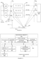
- FIG. 4 is a block diagram which illustrates exemplary components which may be provided by a system (400) for determining currents for injection into or extraction from a power network according to aspects of the present disclosure.
- the system (400) may include a device (104) which provides or has access to a current compensation system (106).
- the device (104) may include the current compensation system (106) or may be physically and/or logically separated therefrom yet in data communication therewith.
- the device (104) and/or current compensation system (106) may include a processor (402) for executing the functions of components described below, which may be provided by hardware or by software units executing on the device (104) and/or current compensation system (106), as the case may be.
- the software units may be stored in a memory component (404) and instructions may be provided to the processor (402) to carry out the functionality of the described components.
- the current compensation system (106) includes a Thévenin parameter data structure compiling component (410).
- the Thévenin parameter data structure compiling component (410) is arranged to compile Thévenin parameter data structures for one or more of a Thévenin voltage, resistance and inductance. Each data structure has values for each of the one or more lines (or wires) at each of a predetermined set of frequencies obtained at the point of common coupling of the device to a power network (102).
- the current compensation system (106) includes an offset data structure compiling component (412) arranged to compile an offset data structure.
- the offset data structure includes offset values, each of which is to be applied to a corresponding value of the Thévenin voltage data structure to output an offset Thévenin voltage data structure.
- the offset values are calculated to satisfy physical constraints associated with the power network (102).
- the current compensation system (106) includes an offset Thévenin voltage data structure compiling component (414) arranged to compile the offset Thévenin voltage data structure.
- the current compensation system (106) includes an optimal point of common coupling power data structure compiling component (416).
- the optimal point of common coupling power data structure compiling component (416) is arranged to compile an optimal point of common coupling power data structure including values having been determined based on a specific amount of total power at the point of common coupling and the offset Thévenin voltage data structure or a derivative thereof.
- the current compensation system (106) includes a current component calculating component (418) arranged to calculate current components for each line and for each of the predetermined set of frequencies.
- the current components are calculated using the optimal point of common coupling power data structure and the offset Thévenin voltage data structure.
- the current components are calculated for injection into or extraction from corresponding lines at the point of common coupling so as to inject or extract a specific total amount of power in a manner that reduces total electrical transmission losses of the power network.
- the current compensation system (106) includes a current injecting/extracting component (420) for controlling injection or extraction of currents associated with the current components to reduce total electrical transmission losses of the power network.
- the currents are injected or extracted, as the case may be, at the point of common coupling.
- the current injecting/extracting component (420) may be configured to instruct or control the device (104) to inject or extract currents at the point of common coupling based on the current component values.
- the system (400) may include a connector (422) configured for electrically connecting the device (104) and/or current compensation system (106) to the power network (102) at the point of common coupling.
- the system (400) may include a measurement component (424) which measures voltage signals and line currents at the point of common coupling via the connector (422).
- the measurement component (424) may further be configured to measure Thévenin resistance and inductance via the connector (422).
- the current injecting/extracting component (420) may control injecting or extracting currents associated with the current components via the connector (422).
- the system (400) may include an apparatus which provides the connector (422) and/or measurement component (424).
- the device (104) includes or incorporates such an apparatus while in other implementations the apparatus may be separate from, but in data communication with, the device (104) such that measurements and other values or data may be shared between the apparatus and device (104).
- 'line' herein includes any wire in a power network and should not be construed to exclude a ground or earth return line or wire.
- data structure as used herein should be interpreted to include any arrangement of data (such as values) configured for storage, use, manipulation and/or processing in a computing device.
- Example data structures may for example include a payload of a digital message, a file, a list, a table, a pointer to a location in memory in which values associated with the data structure are stored, and the like.
- aspects of the present disclosure provide a generalized derivation of active currents in the frequency domain.
- a point of reference for all voltages is transferred to a Thévenin equivalent point.
- Each voltage component, h differs from the others in that each has its own specific reference, not necessarily the same for all frequency components. This necessary “multiple” reference is related to Kirchhoff's current law.
- Aspects of the present application may be robust to: line voltages at the PCC changing after compensation, the presence of non-negligible line resistances, and the presence
- Theoretical development of the system and method described herein may involve one or more of the following stages: setting up the input matrices; a theorem and proof of the relationships between PCC and PTh; identifying the Thévenin side voltage vector; defining the reference offsets from the PCC side; finding VTh (null) by subtracting the offsets; identifying the weighted Thévenin vector; finding P at the Thévenin point and the multiplier K A ; and, identifying the individual CRMS solution current components.
- the problem can be considered as a transportation problem where the same power as before compensation is transported but with minimal power losses.
- Other constraints are: the power consumed (or generated) at the PCC remains constant, and Kirchhoff's current law applies to all line currents and their respective current components.
- Example 1 demonstrates a solution of a measurement with only fundamental frequency waveforms, In Example 2 some harmonic content is added.
- the first example considers three phases without a neutral wire and with only fundamental frequency waveforms (no harmonics).
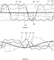
- the example is compiled using arbitrary sinusoidal waveforms and phase shifts to give unbalanced currents, illustrated in Figure 5 , and unequal line resistances and inductances.
- the waveforms can be used to solve for the compensator currents and the power factor before compensation.
- Measurements of line voltages (450, 454, 458, 462) and currents (452, 456, 460, 464) from an arbitrary reference may be obtained and frequency components may be derived.
- the obtained values may be converted to CRMS values, including constructing two M x (H+1) dimensional vectors U and I S .
- Thévenin equivalent impedances R(m,h) and X(m,h) may be used to determine the losses before any compensation.
- Vth(m,n) line voltages may be calculated with respect to the original PCC side common reference.
- the reference offsets may be calculated from original PCC side and V TH (null) may be calculated by subtracting the respective e ref h offsets from V TH (m,h) .
- New PCC line voltages from VTh, the wire impedances and the now optimal line currents may then be calculated. Thereafter, compensation current components I c, m, h to be injected by the compensator may be determined by subtracting I A from I S .
- the second example comprises a three-wire system with the fundamental, dc and 3rd, 5th and 7th harmonic components, and with frequency-dependent impedances.
- the values of the fundamental frequency components are the same as those in Example 1.
- the dc and three harmonic components have been added to shape the voltages towards a square wave and the current components are arbitrary.
- the voltage (470, 474, 478, 482) and current (472, 476, 480, 484) waveforms with dc and harmonic components at the PCC before compensation are illustrated in Figure 7 .
- the compensation current (490, 492, 494, 496) waveforms in each wire at the PCC are illustrated in Figure 8 .
- example 1 A conventional approach to power factor, approximating example 1 with balanced currents and 10° current displacement gives a power factor of 0.98.
- Including the delivery system with unbalanced impedances reduces the power factor to 0.93; with unbalanced sinusoidal voltages and currents the power factor reduces to 0.914 calculated in Example 1; and with the harmonics added it reduces to 0.908, shown in Example 2. All conditions violating assumptions about balanced Thévenin sources and wire impedances, and balanced sinusoidal waveforms affect the calculation of the power factor.
- All components of active current may be one or more of: proportional to a common factor K A ; proportional to each of their respective weighted Thévenin voltages CRMS components V Th ( null )( m,h ) measured from their respective harmonic weighted null point reference; and, inversely proportional to the respective wire resistances.
- Example 3 considers three dc voltage sources (502) supplying power through a 3-wire delivery system to a resistive load (504), as illustrated in Figure 9 . Using the systems and methods described herein, the optimum wire currents that would deliver the power to the load with the minimum losses can be determined.
- the example shows that the generalized power theory approach described herein can improve the operation of multi-wire dc networks.
- Example 4 Optimum inverter-based generation into a distribution network
- a generator injects power at the PCC into a network that, for simplicity of this example, is without distortion and balanced, except for a single-phase resistance load of 13 kW at an intermediate position, which unbalances the Thévenin parameters.
- the Thévenin impedances and voltages are typical of those that have been measured on a 400 V feeder in what may be expected from a light industrial area.
- aspects of the present disclosure enable the identification of minimum and avoidable delivery losses separately, and the required rearrangement of the line currents if compensation is implemented.
- the approach requires that the frequency-dependent Thévenin equivalent network parameters be known, and there are several ways of obtaining these parameters. Implications of the new approach include that the costs of losses can be allocated according to where and how they are incurred, which can guide technical and financial decisions. The approach may also affect international standards, tariff metering, the control of inverters and compensators, load flow analysis software, and smart grids.
- FIG. 10 illustrates an example of a computing device (600) in which various aspects of the disclosure may be implemented.
- the computing device (600) may be embodied as any form of data processing device including a personal computing device (e.g. laptop or desktop computer), a server computer (which may be self-contained, physically distributed over a number of locations), a client computer, or a communication device, such as a mobile phone (e.g. cellular telephone), satellite phone, tablet computer, personal digital assistant or the like.
- a mobile phone e.g. cellular telephone
- satellite phone e.g. cellular telephone
- tablet computer e.g. cellular telephone
- personal digital assistant e.g. cellular telephone
- the computing device (600) may be suitable for storing and executing computer program code.
- the various participants and elements in the previously described system diagrams may use any suitable number of subsystems or components of the computing device (600) to facilitate the functions described herein.
- the computing device (600) may include subsystems or components interconnected via a communication infrastructure (605) (for example, a communications bus, a network, etc.).
- the computing device (600) may include one or more processors (610) and at least one memory component in the form of computer-readable media.
- the one or more processors (610) may include one or more of: CPUs, graphical processing units (GPUs), microprocessors, field programmable gate arrays (FPGAs), application specific integrated circuits (ASICs) and the like.
- a number of processors may be provided and may be arranged to carry out calculations simultaneously.
- various subsystems or components of the computing device (600) may be distributed over a number of physical locations (e.g. in a distributed, cluster or cloud-based computing configuration) and appropriate software units may be arranged to manage and/or process data on behalf of remote devices.
- the memory components may include system memory (615), which may include read only memory (ROM) and random access memory (RAM).
- ROM read only memory
- RAM random access memory
- BIOS basic input/output system
- System software may be stored in the system memory (615) including operating system software.
- the memory components may also include secondary memory (620).
- the secondary memory (620) may include a fixed disk (621), such as a hard disk drive, solid state drive, etc., and, optionally, one or more storage interfaces (622) for interfacing with storage components (623), such as removable storage components (e.g. magnetic tape, optical disk, flash memory drive, external hard drive, removable memory chip, etc.), network attached storage components (e.g. NAS drives), remote storage components (e.g. cloud-based storage) or the like.
- storage components e.g. magnetic tape, optical disk, flash memory drive, external hard drive, removable memory chip, etc.
- network attached storage components e.g. NAS drives
- remote storage components e.g. cloud-based storage
- the computing device (600) may include an external communications interface (630) for operation of the computing device (600) in a networked environment enabling transfer of data between multiple computing devices (600) and/or the Internet.
- Data transferred via the external communications interface (630) may be in the form of signals, which may be electronic, electromagnetic, optical, radio, or other types of signal.
- the external communications interface (630) may enable communication of data between the computing device (600) and other computing devices including servers and external storage facilities. Web services may be accessible by and/or from the computing device (600) via the communications interface (630).
- the external communications interface (630) may be configured for connection to wireless communication channels (e.g., a cellular telephone network (3G, LTE, etc.), wireless local area network (e.g. using Wi-Fi TM ), satellite-phone network, Satellite Internet Network, etc.) and may include an associated wireless transfer element, such as an antenna and associated circuitry.
- wireless communication channels e.g., a cellular telephone network (3G, LTE, etc.), wireless local area network (e.g. using Wi-Fi TM ), satellite-phone network, Satellite Internet Network, etc.
- wireless transfer element such as an antenna and associated circuitry.
- the computer-readable media in the form of the various memory components may provide storage of computer-executable instructions, data structures, program modules, software units and other data.
- a computer program product may be provided by a computer-readable medium having stored computer-readable program code executable by the central processor (610).
- a computer program product may be provided by a non-transient computer-readable medium, or may be provided via a signal or other transient means via the communications interface (630).
- Interconnection via the communication infrastructure (605) allows the one or more processors (610) to communicate with each subsystem or component and to control the execution of instructions from the memory components, as well as the exchange of information between subsystems or components.
- Peripherals such as printers, scanners, cameras, or the like
- input/output (I/O) devices such as a mouse, touchpad, keyboard, microphone, touch-sensitive display, input buttons, speakers and the like
- I/O controller (635) may couple to or be integrally formed with the computing device (600) either directly or via an I/O controller (635).
- One or more displays (645) (which may be touch-sensitive displays) may be coupled to or integrally formed with the computing device (600) via a display (645) or video adapter (640).
- a software unit is implemented with a computer program product comprising a non-transient computer-readable medium containing computer program code, which can be executed by a processor for performing any or all of the steps, operations, or processes described.
- Software units or functions described in this application may be implemented as computer program code using any suitable computer language such as, for example, Java TM , C++, or Perl TM using, for example, conventional or object-oriented techniques.
- the computer program code may be stored as a series of instructions, or commands on a non-transitory computer-readable medium, such as a random access memory (RAM), a read-only memory (ROM), a magnetic medium such as a hard-drive, or an optical medium such as a CD-ROM. Any such computer-readable medium may also reside on or within a single computational apparatus, and may be present on or within different computational apparatuses within a system or network.
- a non-transitory computer-readable medium such as a random access memory (RAM), a read-only memory (ROM), a magnetic medium such as a hard-drive, or an optical medium such as a CD-ROM.
- Any such computer-readable medium may also reside on or within a single computational apparatus, and may be present on or within different computational apparatuses within a system or network.
- Flowchart illustrations and block diagrams of methods, systems, and computer program products according to embodiments are used herein. Each block of the flowchart illustrations and/or block diagrams, and combinations of blocks in the
- the functions identified by the blocks may take place in a different order to that shown in the flowchart illustrations.
- Some portions of this description describe the embodiments of the invention in terms of algorithms and symbolic representations of operations on information. These algorithmic descriptions and representations are commonly used by those skilled in the data processing arts to convey the substance of their work effectively to others skilled in the art. These operations, while described functionally, computationally, or logically, are understood to be implemented by computer programs or equivalent electrical circuits, microcode, or the like. The described operations may be embodied in software, firmware, hardware, or any combinations thereof.
Landscapes
- Engineering & Computer Science (AREA)
- Power Engineering (AREA)
- Supply And Distribution Of Alternating Current (AREA)
Claims (12)
- Computerimplementiertes Verfahren zur frequenzbereichsbasierten Bestimmung von Strömen zur Einspeisung in ein Stromnetz, das Verfahren umfassend:Kompilieren (208) von Thévenin-Parameterdatenstrukturen für jedes von einer Thévenin-Spannung, -Widerstand und -Induktivität, wobei jede Datenstruktur Werte für jede von einer oder mehreren Leitungen bei jedem eines vorbestimmten Satzes von Frequenzen aufweist, wobei die Werte an einem gemeinsamen Kopplungspunkt mit einem Stromnetz erlangt werden, das die eine oder die mehreren Leitungen aufweist;Kompilieren (212) einer Offset-Datenstruktur, die Offset-Werte beinhaltet, wovon jeder auf einen entsprechenden Wert der Thévenin-Spannungsdatenstruktur anzuwenden ist, um eine Offset-Thévenin-Spannungsdatenstruktur auszugeben, wobei die Offset-Werte berechnet werden, um physikalische Beschränkungen zu erfüllen, die mit dem Stromnetz assoziiert sind;Kompilieren (214) der Offset-Thévenin-Spannungsdatenstruktur;Kompilieren (216) einer optimalen Stromdatenstruktur eines gemeinsamen Kopplungspunkts, die Werte beinhaltet, die basierend auf einem bestimmten Betrag eines Gesamtstroms an dem gemeinsamen Kopplungspunkt und der minimal erreichbaren Leitungsverluste, die auf der Offset-Thévenin-Spannungsdatenstruktur oder einer Ableitung davon basieren, bestimmt wurden;Verwenden (218) der Stromdatenstruktur eines gemeinsamen Kopplungspunkts und der Offset-Thévenin-Spannungsdatenstruktur zum Berechnen von Stromkomponenten für jede Leitung und für jede des vorbestimmten Satzes von Frequenzen zum Bestimmen des Stroms zur Einspeisung in oder die Entnahme aus entsprechenden Leitungen an dem gemeinsamen Kopplungspunkt, um einen bestimmten Gesamtbetrag an Strom auf eine Weise einzuspeisen oder zu entnehmen, die die gesamten elektrischen Übertragungsverluste des Stromnetzes reduziert; undSteuern (220) des Einspeisens oder Entnehmens, an dem gemeinsamen Kopplungspunkt, der mit den Stromkomponenten assoziierten Ströme, um die gesamten elektrischen Übertragungsverluste des Stromnetzes zu reduzieren.
- Verfahren nach Anspruch 1, das ein Bestimmen (210) der Offset-Werte beinhaltet, wobei ein Bestimmen der Offset-Werte auf einer Projektion der Thévenin-Spannungsdatenstruktur oder einer gewichteten Thévenin-Spannungsdatenstruktur auf Vektoren in einem Lösungsunterraum basiert, in dem die Stromkomponenten residieren sollen.
- Verfahren nach Anspruch 2, wobei die Vektoren in dem Lösungsunterraum durch Lösungsunterraum-Datenstrukturen dargestellt sind.
- Verfahren nach Anspruch 2 oder Anspruch 3, wobei für jede der Anzahl von Frequenzen in dem vorbestimmten Satz von Frequenzen eine Lösungsunterraum-Datenstruktur bereitgestellt ist und wobei die Werte jeder der Lösungsunterraum-Datenstrukturen Vektoren darstellen, die orthogonal zueinander sind.
- Verfahren nach einem der vorherigen Ansprüche, wobei die Offset-Werte berechnet werden, um physikalische Beschränkungen zu erfüllen, einschließlich eines oder beider von dem Kirchhoffschen Gesetz und der Anforderung, dass die Werte der optimalen Stromdatenstruktur an dem gemeinsamen Kopplungspunkt vor und nach Einspeisung oder Entnahme der Stromkomponenten gleich bleiben.
- Verfahren nach einem der Ansprüche 3 bis 5, wobei die Werte der Lösungsunterraum-Datenstrukturen die Werte der Thévenin-Widerstands- und Induktivitäts-Datenstruktur beinhalten.
- Verfahren nach einem der vorherigen Ansprüche, wobei die Werte der Thévenin-Parameterdatenstrukturen zeitvariable Werte in Form von frequenzbereichsbasierten komplexen quadratischen Mittelwerten, CRMS, sind.
- Verfahren nach einem der vorherigen Ansprüche, wobei das Verfahren an dem gemeinsamen Kopplungspunkt durch eine mit dem Stromnetz gekoppelte Vorrichtung durchgeführt wird.
- Verfahren nach einem der vorherigen Ansprüche, wobei der spezifische Betrag der Gesamtleistung an dem gemeinsamen Kopplungspunkt ein spezifischer Betrag der durchschnittlichen Gesamtleistung über eine vorbestimmte Zeitspanne ist.
- System zur frequenzbereichsbasierten Bestimmung von Strömen zur Einspeisung in ein Stromnetz, wobei das System einen Speicher zum Speichern von computerlesbarem Programmcode und einen Prozessor zum Ausführen des computerlesbaren Programmcodes beinhaltet, das System umfassend:eine Thévenin-Parameter-Datenstruktur-Kompilierungskomponente (410) zum Kompilieren von Thévenin-Parameter-Datenstrukturen für jedes von einer Thévenin-Spannung, - Widerstand und -Induktivität, wobei jede Datenstruktur Werte für jede von einer oder mehreren Leitungen bei jedem eines vorbestimmten Satzes von Frequenzen aufweist, wobei die Werte an einem Punkt gemeinsamer Kopplung mit einem Stromnetz erlangt werden, das die eine oder die mehreren Leitungen aufweist;eine Offset-Datenstruktur-Kompilierunskomponente (412) zum Kompilieren einer Offset-Datenstruktur, die Offset-Werte beinhaltet, wovon jeder auf einen entsprechenden Wert der Thévenin-Spannungsdatenstruktur anzuwenden ist, um eine Offset-Thévenin-Spannungsdatenstruktur auszugeben, wobei die Offset-Werte berechnet werden, um physikalische Beschränkungen zu erfüllen, die mit dem Stromnetz assoziiert sind;eine Offset-Thévenin-Spannungsdatenstruktur-Kompilierungskomponente (414) zum Kompilieren der Offset-Thévenin-Spannungsdatenstruktur;eine Stromdatenstruktur-Kompilierungskomponente (416) eines gemeinsamen Kopplungspunkts zum Kompilieren einer optimalen Stromdatenstruktur eines gemeinsamen Kopplungspunkts, die Werte beinhaltet, die basierend auf einem bestimmten Betrag eines Gesamtstroms an dem gemeinsamen Kopplungspunkt und der minimal erreichbaren Leitungsverluste, die auf der Offset-Thévenin-Spannungsdatenstruktur oder einer Ableitung davon basieren, bestimmt wurden;eine Stromkomponenten-Berechnungskomponente (418), um unter Verwendung der Stromdatenstruktur des gemeinsamen Kopplungspunkts und der Offset-Thévenin-Spannungsdatenstruktur Stromkomponenten für jede Leitung und für jeden des vorbestimmten Satzes von Frequenzen zum Bestimmen des Stroms zur Einspeisung in oder die Entnahme aus entsprechenden Leitungen an dem gemeinsamen Kopplungspunkt zu berechnen, um einen bestimmten Gesamtbetrag an Strom auf eine Weise einzuspeisen oder zu entnehmen, die die gesamten elektrischen Übertragungsverluste des Stromnetzes reduziert; undeine Stromeinspeise-/Entnahmekomponente (420) zum Steuern des Einspeisens oder Entnehmens, an dem gemeinsamen Kopplungspunkt, der mit den Stromkomponenten assoziierten Ströme, um die gesamten elektrischen Übertragungsverluste des Stromnetzes zu reduzieren.
- System nach Anspruch 10, das einen Verbinder (422) beinhaltet, der konfiguriert ist, um an dem gemeinsamen Kopplungspunkt eine elektrische Verbindung mit dem Stromnetz herzustellen, wobei die Stromeinspeise-/Entnahmekomponente ein Einspeisen oder Entnehmen von mit den Stromkomponenten assoziierten Strömen über den Verbinder steuert.
- Computerprogrammprodukt zur frequenzbereichsbasierten Bestimmung von Strömen zur Einspeisung in ein Stromnetz, wobei das Computerprogrammprodukt ein computerlesbares Medium mit gespeichertem computerlesbarem Programmcode zum Ausführen der folgenden Schritte umfasst:Kompilieren von Thévenin-Parameter-Datenstrukturen für jedes von einer Thévenin-Spannung, -Widerstand und -Induktivität, wobei jede Datenstruktur Werte für jede von einer oder mehreren Leitungen bei jedem eines vorbestimmten Satzes von Frequenzen aufweist, wobei die Werte an einem Punkt gemeinsamer Kopplung mit einem Stromnetz erlangt werden, das die eine oder die mehreren Leitungen aufweist;Kompilieren einer Offset-Datenstruktur, die Offset-Werte beinhaltet, wovon jeder auf einen entsprechenden Wert der Thévenin-Spannungsdatenstruktur anzuwenden ist, um eine Offset-Thévenin-Spannungsdatenstruktur auszugeben, wobei die Offset-Werte berechnet werden, um physikalische Beschränkungen zu erfüllen, die mit dem Stromnetz assoziiert sind;Kompilieren der Offset-Thévenin-Spannungsdatenstruktur;Kompilieren einer optimalen Stromdatenstruktur eines gemeinsamen Kopplungspunkts, die Werte beinhaltet, die basierend auf einem bestimmten Betrag eines Gesamtstroms an dem gemeinsamen Kopplungspunkt und der minimal erreichbaren Leitungsverluste, die auf der Offset-Thévenin-Spannungsdatenstruktur oder einer Ableitung davon basieren, bestimmt wurden;Verwenden der Stromdatenstruktur eines gemeinsamen Kopplungspunkts und der Offset-Thévenin-Spannungsdatenstruktur zum Berechnen von Stromkomponenten für jede Leitung und für jeden des vorbestimmten Satzes von Frequenzen zum Bestimmen des Stroms zur Einspeisung in oder die Entnahme aus entsprechenden Leitungen an dem gemeinsamen Kopplungspunkt, um einen bestimmten Gesamtbetrag an Strom auf eine Weise einzuspeisen oder zu entnehmen, die die gesamten elektrischen Übertragungsverluste des Stromnetzes reduziert; undSteuern eines Einspeisens oder Entnehmens, an dem gemeinsamen Kopplungspunkt, der mit den Stromkomponenten assozierten Ströme, um die gesamten elektrischen Übertragungsverluste des Stromnetzes zu reduzieren.
Applications Claiming Priority (2)
| Application Number | Priority Date | Filing Date | Title |
|---|---|---|---|
| GB1904736.4A GB2582914B (en) | 2019-04-04 | 2019-04-04 | Frequency domain-based determination of currents for injection into a power network |
| PCT/IB2020/053211 WO2020202100A1 (en) | 2019-04-04 | 2020-04-03 | Frequency domain-based determination of currents for injection into a power network |
Publications (2)
| Publication Number | Publication Date |
|---|---|
| EP3948474A1 EP3948474A1 (de) | 2022-02-09 |
| EP3948474B1 true EP3948474B1 (de) | 2023-03-29 |
Family
ID=66809441
Family Applications (1)
| Application Number | Title | Priority Date | Filing Date |
|---|---|---|---|
| EP20718821.0A Active EP3948474B1 (de) | 2019-04-04 | 2020-04-03 | Frequenzdomänenbasierte bestimmung von strömen zur injektion in ein stromnetz |
Country Status (6)
| Country | Link |
|---|---|
| US (1) | US11843249B2 (de) |
| EP (1) | EP3948474B1 (de) |
| CN (1) | CN113678084B (de) |
| GB (1) | GB2582914B (de) |
| WO (1) | WO2020202100A1 (de) |
| ZA (1) | ZA202106801B (de) |
Families Citing this family (1)
| Publication number | Priority date | Publication date | Assignee | Title |
|---|---|---|---|---|
| CN118523400A (zh) * | 2024-04-10 | 2024-08-20 | 广东电网有限责任公司佛山供电局 | 非对称故障下vsc的双序注入电流可行域构建方法 |
Family Cites Families (6)
| Publication number | Priority date | Publication date | Assignee | Title |
|---|---|---|---|---|
| US8473250B2 (en) * | 2006-12-06 | 2013-06-25 | Solaredge, Ltd. | Monitoring of distributed power harvesting systems using DC power sources |
| GB2521414B (en) * | 2013-12-19 | 2016-01-27 | Univ Cape Town | Optimal currents for power injection or extraction in a power network |
| CN104868482B (zh) * | 2015-05-06 | 2017-12-12 | 国家电网公司 | 一种使配电网络全天有功损耗最小的电容补偿系统 |
| DE102016102593B4 (de) | 2016-02-15 | 2017-08-31 | Maschinenfabrik Reinhausen Gmbh | Verfahren zum Steuern eines Regeltransformators und elektrische Anlage zum Koppeln zweier Wechselstromnetze |
| GB2567460B (en) | 2017-10-12 | 2020-02-12 | Univ Cape Town | Method and apparatus for obtaining Thévenin equivalent parameters of a power network |
| CN109066669B (zh) * | 2018-09-12 | 2020-06-12 | 清华四川能源互联网研究院 | 电力系统仿真方法、电力系统仿真装置及电子设备 |
-
2019
- 2019-04-04 GB GB1904736.4A patent/GB2582914B/en active Active
-
2020
- 2020-04-03 WO PCT/IB2020/053211 patent/WO2020202100A1/en not_active Ceased
- 2020-04-03 CN CN202080026891.1A patent/CN113678084B/zh active Active
- 2020-04-03 US US17/441,142 patent/US11843249B2/en active Active
- 2020-04-03 EP EP20718821.0A patent/EP3948474B1/de active Active
-
2021
- 2021-09-14 ZA ZA2021/06801A patent/ZA202106801B/en unknown
Also Published As
| Publication number | Publication date |
|---|---|
| EP3948474A1 (de) | 2022-02-09 |
| US11843249B2 (en) | 2023-12-12 |
| ZA202106801B (en) | 2022-08-31 |
| US20220158451A1 (en) | 2022-05-19 |
| WO2020202100A1 (en) | 2020-10-08 |
| CN113678084A (zh) | 2021-11-19 |
| GB2582914B (en) | 2021-09-29 |
| GB201904736D0 (en) | 2019-05-22 |
| CN113678084B (zh) | 2022-11-01 |
| GB2582914A (en) | 2020-10-14 |
Similar Documents
| Publication | Publication Date | Title |
|---|---|---|
| AU2014369228B2 (en) | Methods and systems for power injection or extraction in a power network | |
| Malengret et al. | Active currents, power factor, and apparent power for practical power delivery systems | |
| Hu et al. | Decentralised control for reactive power sharing using adaptive virtual impedance | |
| CN108292842B (zh) | 直流微电网的功率共享 | |
| US20110257933A1 (en) | System and method for monitoring and managing three-phase power flows in electrical transmission and distribution networks | |
| Malengret et al. | General theory of average power for multi-phase systems with distortion, unbalance and direct current components | |
| Watson et al. | Harmonics in large systems | |
| EP3948474B1 (de) | Frequenzdomänenbasierte bestimmung von strömen zur injektion in ein stromnetz | |
| Bialobrzheskyi et al. | Innovative technique for evaluating electric power distortion in cable transmission line | |
| Gaunt et al. | True power factor metering for m-wire systems with distortion, unbalance and direct current components | |
| CN116054120A (zh) | 直流微电网功率控制方法、系统、设备及存储介质 | |
| CN106877330B (zh) | 一种分布式微电网无功均分控制方法及控制装置 | |
| KR20160127254A (ko) | 저압직류 배전계통의 중성선 전위를 고려한 선로 전압 강하 보상 방식의 송출 전압 제어 시스템 및 방법 | |
| Srinivasan | Errors in digital measurement of voltage, active and reactive powers and an on-line correction for frequency drift | |
| Seo et al. | A novel frequency estimation algorithm based on DFT and second derivative | |
| US20210132124A1 (en) | Crosstalk cancelation for electricity metering | |
| Watson | Harmonic assessment of electrical power systems | |
| Gaunt et al. | Is Reactive Power a Zero-Quantity? | |
| Geethanjali et al. | Discrete wavelet transform based fault detection and classification in a static synchronous series compensated transmission system | |
| Pfajfar et al. | Harmonic emission level estimation based on measurements at the point of evaluation | |
| Ponnala et al. | Development and Implementation of Synchronized Phasor Measurements for Dynamic State Power System Monitoring and Fault Identification | |
| CN120703462A (zh) | 电荷波动雷电通道分析方法、装置、电子设备及存储介质 | |
| Huisinga et al. | Order reduction in electrical power systems using singular perturbation in different coordinate systems | |
| HK40074304A (en) | Crosstalk cancelation for electricity metering | |
| HK40074304B (en) | Crosstalk cancelation for electricity metering |
Legal Events
| Date | Code | Title | Description |
|---|---|---|---|
| STAA | Information on the status of an ep patent application or granted ep patent |
Free format text: STATUS: UNKNOWN |
|
| STAA | Information on the status of an ep patent application or granted ep patent |
Free format text: STATUS: THE INTERNATIONAL PUBLICATION HAS BEEN MADE |
|
| PUAI | Public reference made under article 153(3) epc to a published international application that has entered the european phase |
Free format text: ORIGINAL CODE: 0009012 |
|
| STAA | Information on the status of an ep patent application or granted ep patent |
Free format text: STATUS: REQUEST FOR EXAMINATION WAS MADE |
|
| STAA | Information on the status of an ep patent application or granted ep patent |
Free format text: STATUS: EXAMINATION IS IN PROGRESS |
|
| 17P | Request for examination filed |
Effective date: 20211014 |
|
| AK | Designated contracting states |
Kind code of ref document: A1 Designated state(s): AL AT BE BG CH CY CZ DE DK EE ES FI FR GB GR HR HU IE IS IT LI LT LU LV MC MK MT NL NO PL PT RO RS SE SI SK SM TR |
|
| 17Q | First examination report despatched |
Effective date: 20220128 |
|
| DAV | Request for validation of the european patent (deleted) | ||
| DAX | Request for extension of the european patent (deleted) | ||
| GRAP | Despatch of communication of intention to grant a patent |
Free format text: ORIGINAL CODE: EPIDOSNIGR1 |
|
| STAA | Information on the status of an ep patent application or granted ep patent |
Free format text: STATUS: GRANT OF PATENT IS INTENDED |
|
| INTG | Intention to grant announced |
Effective date: 20221012 |
|
| GRAS | Grant fee paid |
Free format text: ORIGINAL CODE: EPIDOSNIGR3 |
|
| GRAA | (expected) grant |
Free format text: ORIGINAL CODE: 0009210 |
|
| STAA | Information on the status of an ep patent application or granted ep patent |
Free format text: STATUS: THE PATENT HAS BEEN GRANTED |
|
| RBV | Designated contracting states (corrected) |
Designated state(s): AL AT BE BG CH CY CZ DE DK EE ES FI FR GR HR HU IE IS IT LI LT LU LV MC MK MT NL NO PL PT RO RS SE SI SK SM TR |
|
| AK | Designated contracting states |
Kind code of ref document: B1 Designated state(s): AL AT BE BG CH CY CZ DE DK EE ES FI FR GR HR HU IE IS IT LI LT LU LV MC MK MT NL NO PL PT RO RS SE SI SK SM TR |
|
| REG | Reference to a national code |
Ref country code: CH Ref legal event code: EP |
|
| REG | Reference to a national code |
Ref country code: DE Ref legal event code: R096 Ref document number: 602020009255 Country of ref document: DE |
|
| REG | Reference to a national code |
Ref country code: AT Ref legal event code: REF Ref document number: 1557136 Country of ref document: AT Kind code of ref document: T Effective date: 20230415 |
|
| REG | Reference to a national code |
Ref country code: IE Ref legal event code: FG4D |
|
| REG | Reference to a national code |
Ref country code: LT Ref legal event code: MG9D |
|
| PG25 | Lapsed in a contracting state [announced via postgrant information from national office to epo] |
Ref country code: RS Free format text: LAPSE BECAUSE OF FAILURE TO SUBMIT A TRANSLATION OF THE DESCRIPTION OR TO PAY THE FEE WITHIN THE PRESCRIBED TIME-LIMIT Effective date: 20230329 Ref country code: NO Free format text: LAPSE BECAUSE OF FAILURE TO SUBMIT A TRANSLATION OF THE DESCRIPTION OR TO PAY THE FEE WITHIN THE PRESCRIBED TIME-LIMIT Effective date: 20230629 Ref country code: LV Free format text: LAPSE BECAUSE OF FAILURE TO SUBMIT A TRANSLATION OF THE DESCRIPTION OR TO PAY THE FEE WITHIN THE PRESCRIBED TIME-LIMIT Effective date: 20230329 Ref country code: LT Free format text: LAPSE BECAUSE OF FAILURE TO SUBMIT A TRANSLATION OF THE DESCRIPTION OR TO PAY THE FEE WITHIN THE PRESCRIBED TIME-LIMIT Effective date: 20230329 Ref country code: HR Free format text: LAPSE BECAUSE OF FAILURE TO SUBMIT A TRANSLATION OF THE DESCRIPTION OR TO PAY THE FEE WITHIN THE PRESCRIBED TIME-LIMIT Effective date: 20230329 |
|
| REG | Reference to a national code |
Ref country code: NL Ref legal event code: MP Effective date: 20230329 |
|
| REG | Reference to a national code |
Ref country code: AT Ref legal event code: MK05 Ref document number: 1557136 Country of ref document: AT Kind code of ref document: T Effective date: 20230329 |
|
| PG25 | Lapsed in a contracting state [announced via postgrant information from national office to epo] |
Ref country code: SE Free format text: LAPSE BECAUSE OF FAILURE TO SUBMIT A TRANSLATION OF THE DESCRIPTION OR TO PAY THE FEE WITHIN THE PRESCRIBED TIME-LIMIT Effective date: 20230329 Ref country code: NL Free format text: LAPSE BECAUSE OF FAILURE TO SUBMIT A TRANSLATION OF THE DESCRIPTION OR TO PAY THE FEE WITHIN THE PRESCRIBED TIME-LIMIT Effective date: 20230329 Ref country code: GR Free format text: LAPSE BECAUSE OF FAILURE TO SUBMIT A TRANSLATION OF THE DESCRIPTION OR TO PAY THE FEE WITHIN THE PRESCRIBED TIME-LIMIT Effective date: 20230630 Ref country code: FI Free format text: LAPSE BECAUSE OF FAILURE TO SUBMIT A TRANSLATION OF THE DESCRIPTION OR TO PAY THE FEE WITHIN THE PRESCRIBED TIME-LIMIT Effective date: 20230329 |
|
| P01 | Opt-out of the competence of the unified patent court (upc) registered |
Effective date: 20230801 |
|
| PG25 | Lapsed in a contracting state [announced via postgrant information from national office to epo] |
Ref country code: SM Free format text: LAPSE BECAUSE OF FAILURE TO SUBMIT A TRANSLATION OF THE DESCRIPTION OR TO PAY THE FEE WITHIN THE PRESCRIBED TIME-LIMIT Effective date: 20230329 Ref country code: RO Free format text: LAPSE BECAUSE OF FAILURE TO SUBMIT A TRANSLATION OF THE DESCRIPTION OR TO PAY THE FEE WITHIN THE PRESCRIBED TIME-LIMIT Effective date: 20230329 Ref country code: PT Free format text: LAPSE BECAUSE OF FAILURE TO SUBMIT A TRANSLATION OF THE DESCRIPTION OR TO PAY THE FEE WITHIN THE PRESCRIBED TIME-LIMIT Effective date: 20230731 Ref country code: ES Free format text: LAPSE BECAUSE OF FAILURE TO SUBMIT A TRANSLATION OF THE DESCRIPTION OR TO PAY THE FEE WITHIN THE PRESCRIBED TIME-LIMIT Effective date: 20230329 Ref country code: EE Free format text: LAPSE BECAUSE OF FAILURE TO SUBMIT A TRANSLATION OF THE DESCRIPTION OR TO PAY THE FEE WITHIN THE PRESCRIBED TIME-LIMIT Effective date: 20230329 Ref country code: AT Free format text: LAPSE BECAUSE OF FAILURE TO SUBMIT A TRANSLATION OF THE DESCRIPTION OR TO PAY THE FEE WITHIN THE PRESCRIBED TIME-LIMIT Effective date: 20230329 |
|
| PG25 | Lapsed in a contracting state [announced via postgrant information from national office to epo] |
Ref country code: SK Free format text: LAPSE BECAUSE OF FAILURE TO SUBMIT A TRANSLATION OF THE DESCRIPTION OR TO PAY THE FEE WITHIN THE PRESCRIBED TIME-LIMIT Effective date: 20230329 Ref country code: PL Free format text: LAPSE BECAUSE OF FAILURE TO SUBMIT A TRANSLATION OF THE DESCRIPTION OR TO PAY THE FEE WITHIN THE PRESCRIBED TIME-LIMIT Effective date: 20230329 Ref country code: IS Free format text: LAPSE BECAUSE OF FAILURE TO SUBMIT A TRANSLATION OF THE DESCRIPTION OR TO PAY THE FEE WITHIN THE PRESCRIBED TIME-LIMIT Effective date: 20230729 |
|
| REG | Reference to a national code |
Ref country code: CH Ref legal event code: PL |
|
| PG25 | Lapsed in a contracting state [announced via postgrant information from national office to epo] |
Ref country code: LU Free format text: LAPSE BECAUSE OF NON-PAYMENT OF DUE FEES Effective date: 20230403 |
|
| REG | Reference to a national code |
Ref country code: DE Ref legal event code: R097 Ref document number: 602020009255 Country of ref document: DE |
|
| REG | Reference to a national code |
Ref country code: BE Ref legal event code: MM Effective date: 20230430 |
|
| PG25 | Lapsed in a contracting state [announced via postgrant information from national office to epo] |
Ref country code: MC Free format text: LAPSE BECAUSE OF FAILURE TO SUBMIT A TRANSLATION OF THE DESCRIPTION OR TO PAY THE FEE WITHIN THE PRESCRIBED TIME-LIMIT Effective date: 20230329 |
|
| PG25 | Lapsed in a contracting state [announced via postgrant information from national office to epo] |
Ref country code: MC Free format text: LAPSE BECAUSE OF FAILURE TO SUBMIT A TRANSLATION OF THE DESCRIPTION OR TO PAY THE FEE WITHIN THE PRESCRIBED TIME-LIMIT Effective date: 20230329 Ref country code: LI Free format text: LAPSE BECAUSE OF NON-PAYMENT OF DUE FEES Effective date: 20230430 Ref country code: DK Free format text: LAPSE BECAUSE OF FAILURE TO SUBMIT A TRANSLATION OF THE DESCRIPTION OR TO PAY THE FEE WITHIN THE PRESCRIBED TIME-LIMIT Effective date: 20230329 Ref country code: CZ Free format text: LAPSE BECAUSE OF FAILURE TO SUBMIT A TRANSLATION OF THE DESCRIPTION OR TO PAY THE FEE WITHIN THE PRESCRIBED TIME-LIMIT Effective date: 20230329 Ref country code: CH Free format text: LAPSE BECAUSE OF NON-PAYMENT OF DUE FEES Effective date: 20230430 |
|
| PLBE | No opposition filed within time limit |
Free format text: ORIGINAL CODE: 0009261 |
|
| STAA | Information on the status of an ep patent application or granted ep patent |
Free format text: STATUS: NO OPPOSITION FILED WITHIN TIME LIMIT |
|
| REG | Reference to a national code |
Ref country code: IE Ref legal event code: MM4A |
|
| PG25 | Lapsed in a contracting state [announced via postgrant information from national office to epo] |
Ref country code: BE Free format text: LAPSE BECAUSE OF NON-PAYMENT OF DUE FEES Effective date: 20230430 |
|
| 26N | No opposition filed |
Effective date: 20240103 |
|
| PG25 | Lapsed in a contracting state [announced via postgrant information from national office to epo] |
Ref country code: IE Free format text: LAPSE BECAUSE OF NON-PAYMENT OF DUE FEES Effective date: 20230403 |
|
| PG25 | Lapsed in a contracting state [announced via postgrant information from national office to epo] |
Ref country code: IE Free format text: LAPSE BECAUSE OF NON-PAYMENT OF DUE FEES Effective date: 20230403 |
|
| PG25 | Lapsed in a contracting state [announced via postgrant information from national office to epo] |
Ref country code: SI Free format text: LAPSE BECAUSE OF FAILURE TO SUBMIT A TRANSLATION OF THE DESCRIPTION OR TO PAY THE FEE WITHIN THE PRESCRIBED TIME-LIMIT Effective date: 20230329 |
|
| PG25 | Lapsed in a contracting state [announced via postgrant information from national office to epo] |
Ref country code: SI Free format text: LAPSE BECAUSE OF FAILURE TO SUBMIT A TRANSLATION OF THE DESCRIPTION OR TO PAY THE FEE WITHIN THE PRESCRIBED TIME-LIMIT Effective date: 20230329 Ref country code: IT Free format text: LAPSE BECAUSE OF FAILURE TO SUBMIT A TRANSLATION OF THE DESCRIPTION OR TO PAY THE FEE WITHIN THE PRESCRIBED TIME-LIMIT Effective date: 20230329 |
|
| PG25 | Lapsed in a contracting state [announced via postgrant information from national office to epo] |
Ref country code: BG Free format text: LAPSE BECAUSE OF FAILURE TO SUBMIT A TRANSLATION OF THE DESCRIPTION OR TO PAY THE FEE WITHIN THE PRESCRIBED TIME-LIMIT Effective date: 20230329 |
|
| PG25 | Lapsed in a contracting state [announced via postgrant information from national office to epo] |
Ref country code: BG Free format text: LAPSE BECAUSE OF FAILURE TO SUBMIT A TRANSLATION OF THE DESCRIPTION OR TO PAY THE FEE WITHIN THE PRESCRIBED TIME-LIMIT Effective date: 20230329 |
|
| PGFP | Annual fee paid to national office [announced via postgrant information from national office to epo] |
Ref country code: DE Payment date: 20250420 Year of fee payment: 6 |
|
| PGFP | Annual fee paid to national office [announced via postgrant information from national office to epo] |
Ref country code: FR Payment date: 20250420 Year of fee payment: 6 |
|
| PG25 | Lapsed in a contracting state [announced via postgrant information from national office to epo] |
Ref country code: CY Free format text: LAPSE BECAUSE OF FAILURE TO SUBMIT A TRANSLATION OF THE DESCRIPTION OR TO PAY THE FEE WITHIN THE PRESCRIBED TIME-LIMIT; INVALID AB INITIO Effective date: 20200403 |
|
| PG25 | Lapsed in a contracting state [announced via postgrant information from national office to epo] |
Ref country code: HU Free format text: LAPSE BECAUSE OF FAILURE TO SUBMIT A TRANSLATION OF THE DESCRIPTION OR TO PAY THE FEE WITHIN THE PRESCRIBED TIME-LIMIT; INVALID AB INITIO Effective date: 20200403 |
|
| PG25 | Lapsed in a contracting state [announced via postgrant information from national office to epo] |
Ref country code: TR Free format text: LAPSE BECAUSE OF FAILURE TO SUBMIT A TRANSLATION OF THE DESCRIPTION OR TO PAY THE FEE WITHIN THE PRESCRIBED TIME-LIMIT Effective date: 20230329 |