EP3948424B1 - Sealing device, component and lithography apparatus - Google Patents
Sealing device, component and lithography apparatus Download PDFInfo
- Publication number
- EP3948424B1 EP3948424B1 EP20716770.1A EP20716770A EP3948424B1 EP 3948424 B1 EP3948424 B1 EP 3948424B1 EP 20716770 A EP20716770 A EP 20716770A EP 3948424 B1 EP3948424 B1 EP 3948424B1
- Authority
- EP
- European Patent Office
- Prior art keywords
- radius
- sealing device
- connection
- sealing
- inner contour
- Prior art date
- Legal status (The legal status is an assumption and is not a legal conclusion. Google has not performed a legal analysis and makes no representation as to the accuracy of the status listed.)
- Active
Links
Images





Classifications
-
- G—PHYSICS
- G03—PHOTOGRAPHY; CINEMATOGRAPHY; ANALOGOUS TECHNIQUES USING WAVES OTHER THAN OPTICAL WAVES; ELECTROGRAPHY; HOLOGRAPHY
- G03F—PHOTOMECHANICAL PRODUCTION OF TEXTURED OR PATTERNED SURFACES, e.g. FOR PRINTING, FOR PROCESSING OF SEMICONDUCTOR DEVICES; MATERIALS THEREFOR; ORIGINALS THEREFOR; APPARATUS SPECIALLY ADAPTED THEREFOR
- G03F7/00—Photomechanical, e.g. photolithographic, production of textured or patterned surfaces, e.g. printing surfaces; Materials therefor, e.g. comprising photoresists; Apparatus specially adapted therefor
- G03F7/70—Microphotolithographic exposure; Apparatus therefor
- G03F7/70058—Mask illumination systems
- G03F7/70075—Homogenization of illumination intensity in the mask plane by using an integrator, e.g. fly's eye lens, facet mirror or glass rod, by using a diffusing optical element or by beam deflection
-
- F—MECHANICAL ENGINEERING; LIGHTING; HEATING; WEAPONS; BLASTING
- F16—ENGINEERING ELEMENTS AND UNITS; GENERAL MEASURES FOR PRODUCING AND MAINTAINING EFFECTIVE FUNCTIONING OF MACHINES OR INSTALLATIONS; THERMAL INSULATION IN GENERAL
- F16J—PISTONS; CYLINDERS; SEALINGS
- F16J15/00—Sealings
- F16J15/02—Sealings between relatively-stationary surfaces
- F16J15/021—Sealings between relatively-stationary surfaces with elastic packing
-
- G—PHYSICS
- G03—PHOTOGRAPHY; CINEMATOGRAPHY; ANALOGOUS TECHNIQUES USING WAVES OTHER THAN OPTICAL WAVES; ELECTROGRAPHY; HOLOGRAPHY
- G03F—PHOTOMECHANICAL PRODUCTION OF TEXTURED OR PATTERNED SURFACES, e.g. FOR PRINTING, FOR PROCESSING OF SEMICONDUCTOR DEVICES; MATERIALS THEREFOR; ORIGINALS THEREFOR; APPARATUS SPECIALLY ADAPTED THEREFOR
- G03F7/00—Photomechanical, e.g. photolithographic, production of textured or patterned surfaces, e.g. printing surfaces; Materials therefor, e.g. comprising photoresists; Apparatus specially adapted therefor
- G03F7/70—Microphotolithographic exposure; Apparatus therefor
- G03F7/708—Construction of apparatus, e.g. environment aspects, hygiene aspects or materials
- G03F7/70808—Construction details, e.g. housing, load-lock, seals or windows for passing light in or out of apparatus
-
- G—PHYSICS
- G03—PHOTOGRAPHY; CINEMATOGRAPHY; ANALOGOUS TECHNIQUES USING WAVES OTHER THAN OPTICAL WAVES; ELECTROGRAPHY; HOLOGRAPHY
- G03F—PHOTOMECHANICAL PRODUCTION OF TEXTURED OR PATTERNED SURFACES, e.g. FOR PRINTING, FOR PROCESSING OF SEMICONDUCTOR DEVICES; MATERIALS THEREFOR; ORIGINALS THEREFOR; APPARATUS SPECIALLY ADAPTED THEREFOR
- G03F7/00—Photomechanical, e.g. photolithographic, production of textured or patterned surfaces, e.g. printing surfaces; Materials therefor, e.g. comprising photoresists; Apparatus specially adapted therefor
- G03F7/70—Microphotolithographic exposure; Apparatus therefor
- G03F7/708—Construction of apparatus, e.g. environment aspects, hygiene aspects or materials
- G03F7/70808—Construction details, e.g. housing, load-lock, seals or windows for passing light in or out of apparatus
- G03F7/70825—Mounting of individual elements, e.g. mounts, holders or supports
-
- G—PHYSICS
- G03—PHOTOGRAPHY; CINEMATOGRAPHY; ANALOGOUS TECHNIQUES USING WAVES OTHER THAN OPTICAL WAVES; ELECTROGRAPHY; HOLOGRAPHY
- G03F—PHOTOMECHANICAL PRODUCTION OF TEXTURED OR PATTERNED SURFACES, e.g. FOR PRINTING, FOR PROCESSING OF SEMICONDUCTOR DEVICES; MATERIALS THEREFOR; ORIGINALS THEREFOR; APPARATUS SPECIALLY ADAPTED THEREFOR
- G03F7/00—Photomechanical, e.g. photolithographic, production of textured or patterned surfaces, e.g. printing surfaces; Materials therefor, e.g. comprising photoresists; Apparatus specially adapted therefor
- G03F7/70—Microphotolithographic exposure; Apparatus therefor
- G03F7/708—Construction of apparatus, e.g. environment aspects, hygiene aspects or materials
- G03F7/70808—Construction details, e.g. housing, load-lock, seals or windows for passing light in or out of apparatus
- G03F7/70833—Mounting of optical systems, e.g. mounting of illumination system, projection system or stage systems on base-plate or ground
-
- H—ELECTRICITY
- H05—ELECTRIC TECHNIQUES NOT OTHERWISE PROVIDED FOR
- H05K—PRINTED CIRCUITS; CASINGS OR CONSTRUCTIONAL DETAILS OF ELECTRIC APPARATUS; MANUFACTURE OF ASSEMBLAGES OF ELECTRICAL COMPONENTS
- H05K5/00—Casings, cabinets or drawers for electric apparatus
- H05K5/06—Hermetically-sealed casings
- H05K5/061—Hermetically-sealed casings sealed by a gasket held between a removable cover and a body, e.g. O-ring, packing
-
- G—PHYSICS
- G02—OPTICS
- G02B—OPTICAL ELEMENTS, SYSTEMS OR APPARATUS
- G02B27/00—Optical systems or apparatus not provided for by any of the groups G02B1/00 - G02B26/00, G02B30/00
- G02B27/09—Beam shaping, e.g. changing the cross-sectional area, not otherwise provided for
- G02B27/0938—Using specific optical elements
- G02B27/0977—Reflective elements
-
- G—PHYSICS
- G02—OPTICS
- G02B—OPTICAL ELEMENTS, SYSTEMS OR APPARATUS
- G02B27/00—Optical systems or apparatus not provided for by any of the groups G02B1/00 - G02B26/00, G02B30/00
- G02B27/09—Beam shaping, e.g. changing the cross-sectional area, not otherwise provided for
- G02B27/0938—Using specific optical elements
- G02B27/0977—Reflective elements
- G02B27/0983—Reflective elements being curved
-
- G—PHYSICS
- G02—OPTICS
- G02B—OPTICAL ELEMENTS, SYSTEMS OR APPARATUS
- G02B5/00—Optical elements other than lenses
- G02B5/08—Mirrors
- G02B5/09—Multifaceted or polygonal mirrors, e.g. polygonal scanning mirrors; Fresnel mirrors
Definitions
- the present invention relates to a sealing device for a lithography apparatus, to a component for a lithography apparatus comprising a sealing device of this type, and to a lithography apparatus comprising a sealing device of this type and/or a component of this type.
- Microlithography is used for producing microstructured components, for example integrated circuits.
- the microlithography process is performed using a lithography apparatus, which has an illumination system and a projection system.
- the image of a mask (reticle) illuminated by means of the illumination system is in this case projected by means of the projection system onto a substrate (for example a silicon wafer) which is coated with a light-sensitive layer (photoresist) and arranged in the image plane of the projection system, in order to transfer the mask structure to the light-sensitive coating of the substrate.
- a lithography apparatus which has an illumination system and a projection system.
- the image of a mask (reticle) illuminated by means of the illumination system is in this case projected by means of the projection system onto a substrate (for example a silicon wafer) which is coated with a light-sensitive layer (photoresist) and arranged in the image plane of the projection system, in order to transfer the mask structure to the light-sensitive coating of the substrate.
- a substrate for example a silicon wa
- EUV lithography apparatuses that use light with a wavelength in the range from 0.1 nm to 30 nm, in particular 13.5 nm.
- reflective optical units that is to say mirrors
- - refractive optical units that is to say lens elements.
- An EUV lithography apparatus as explained above comprises components having a cooling circuit, for example for cooling the respective component with water, or a purging circuit, for example for purging the respective component with a purge gas, in particular with an inert gas.
- a component of this type can be a so-called actuation sensor unit, for example, with the aid of which facets of a facet mirror, for example of a field facet mirror or of a pupil facet mirror, can be deflected.
- a so-called actuation sensor package is assigned to each facet for the purpose of deflecting the facets.
- the actuation sensor packages should be sealed in a fluid-tight manner vis-à-vis a main body or frame of the actuation sensor unit.
- O-rings or sealing mats can be used as seals.
- the seal In order to maintain the sealing function during operation and over the lifetime, the seal can be clamped onto the respective actuation sensor package by means of prestress or in a manner supported in the pressure direction. A centring of the seal can be obtained as a result.
- the seal requires a yielding volume for the purpose of pressing it. Said yielding volume can be created by keeping enough space available between an inner contour of the respective seal and the actuation sensor package.
- this space is in turn disadvantageous with regard to a good centring of the seal.
- US 2017/108788 A1 discloses a facet mirror comprising a multiplicity of sealing rings.
- a sealing device for sealing a first component part of a lithography apparatus vis-à-vis a multiplicity of second component parts of the lithography apparatus comprises a multiplicity of sealing rings, and a multiplicity of connection locations, wherein the sealing rings are integrally connected to one another with the aid of the connection locations.
- the sealing rings are connected to one another with the aid of the connection locations, the mounting of the sealing device is simplified compared to a sealing device without such connection locations.
- the sealing device can also be referred to as a sealing mat.
- a multiplicity of sealing rings is provided which form a two-dimensional pattern or grid. That is to say that the sealing rings are arranged in particular in the shape of a grid or in the shape of a pattern.
- a plurality of connection locations for example four, are assigned to each sealing ring.
- the connection locations can also be referred to as contact locations.
- the sealing rings are connected to one another integrally, in particular materially in one piece, with the aid of the connection locations.
- “Integrally” means in the present case that the sealing rings together form a common component part, namely the sealing device.
- “Materially in one piece” means here that the sealing device is produced from the same material throughout.
- the sealing device is produced from a plastics material.
- a perfluoro rubber (FFKM) can be used as suitable material.
- the sealing device can be cut out from a sheet or film of a suitable plastics material with the aid of a laser, for example.
- connection locations each comprise a yielding volume for pressing the respective sealing ring between the first component part and one of the second component parts.
- the yielding volume can be provided between an inner contour of the respective sealing ring and a second component part received in the inner contour.
- the yielding volume can also be provided directly in or at the respective connection location, for example in the form of a cutout, a groove, a hole or the like. All that is relevant here is that material of the sealing ring is pressed into the yielding volume during the pressing of the respective sealing ring.
- the abovementioned inner contour of the sealing ring can have an arbitrary shape.
- the inner contour can be circular, oval, triangular, polygonal or the like.
- the inner contour - as will be explained below - can also be trefoiled.
- the yielding volume is provided in particular in or at the sealing device itself.
- each sealing ring comprises an inner contour, in each of which a second component part is able to be received at least in sections, and wherein the yielding volume is formed by virtue of the inner contour widening at the connection locations.
- the inner contour "widens" means in the present case that the inner contour, at least in an unpressed state of the respective sealing ring, does not bear against the corresponding second component part and thus stands away from the second component part, in particular.
- the inner contour comprises a connection radius at the connection locations, wherein the inner contour comprises an intermediate radius in each case between two adjacent connection locations, and wherein the intermediate radius and the connection radius differ from one another in terms of their absolute value in such a way that the inner contour widens at the connection locations and narrows between two adjacent connection locations.
- the sealing device comprises a multiplicity of sealing rings, a multiplicity of connection locations, wherein the sealing rings are connected to one another with the aid of the connection locations, wherein each sealing ring comprises an inner contour, in each of which a second component part is able to be received at least in sections, wherein the inner contour comprises a connection radius at the connection locations, wherein the inner contour comprises an intermediate radius in each case between two adjacent connection locations, and wherein the intermediate radius and the connection radius differ from one another in terms of their absolute value in such a way that the inner contour widens at the connection locations and narrows between two adjacent connection locations.
- the inner contour is composed of a plurality of radii, in particular. That is to say that the inner contour is preferably not circular.
- the inner contour can also have any other geometry, as mentioned above. In the region of the connection locations, the inner contour has a widening or broadening and, in the region between the connection locations, the inner contour has a narrowing, constriction or restriction. This results in a trefoiled or trefoil-like geometry of the inner contour, deviating from the circular shape.
- the inner contour can therefore be referred to as "trefoiled” or "trefoil-like".
- the sealing device is positioned in particular between a sealing surface of the first component part and a sealing surface of the second component part and effects fluid-tight sealing vis-à-vis them.
- the second component part is "able to be received" in the inner contour should be understood in the present case to mean that a respective sealing ring can be put onto the second component part, or vice versa.
- the second component part preferably has a circular-cylindrical base section, at which the sealing ring is centred with the aid of the intermediate radius.
- connection locations are provided.
- the inner contour also has four times the connection radius and four times the intermediate radius.
- the radii transition into one another, such that the inner contour has no shoulders, but rather a curved shape.
- connection radius and the connection radius "differ" from one another should be understood to mean, in particular, that the intermediate radius is greater than the connection radius, or vice versa.
- a centre point of the connection radius can be offset relative to a centre point of the intermediate radius in such a way that the condition that the inner contour widens at the connection locations and narrows between two adjacent connection locations is met both if the connection radius is greater than the intermediate radius and if the connection radius is less than the intermediate radius.
- the intermediate radius is greater than the connection radius.
- connection radius is approximately 5 mm.
- the intermediate radius can be approximately 11 to 12 mm.
- the inner contour comprises a first intermediate radius and a second intermediate radius, wherein the first intermediate radius and the second intermediate radius are equal in magnitude or have different magnitudes.
- the first intermediate radius is greater than the second intermediate radius.
- the first intermediate radius can also be less than the second intermediate radius.
- the connection locations are positioned in a manner spaced apart from one another at different azimuth angles in an azimuth direction or circumferential direction, to take account of the fact that a shortening of the sealing ring by the factor of azimuth angle/360° is to be produced between two connection locations in order, during the mounting of the sealing device, to prevent the connection locations from moving azimuthally, which could otherwise lead to warpage of the sealing device.
- the first intermediate radius and the second intermediate radius are preferably also equal in magnitude.
- connection locations are constructed in each case symmetrically with respect to a line of symmetry assigned to the respective connection location.
- the azimuth angles are measured between the lines of symmetry of the connection locations.
- a respective centre point of the connection radius lies on the line of symmetry of that connection location to which the connection radius is assigned.
- the second intermediate radius has a bigger magnitude than the first intermediate radius.
- the second intermediate radius can also have a smaller magnitude than the first intermediate radius.
- two adjacent connection locations between which the first intermediate radius is provided and two adjacent connection locations between which the second intermediate radius is provided are arranged in a manner spaced apart at the same distance or at different distances from one another.
- connection locations are positioned in a manner spaced apart from one another non-uniformly as viewed in the circumferential direction. That is to say that different azimuth angles are provided between the connection locations.
- the first intermediate radius is positioned between a pair of connection locations between which a smaller azimuth angle is provided.
- the second intermediate radius is provided between a pair of connection locations between which a larger azimuth angle is provided.
- the connection locations are also arranged in a manner spaced apart at an equal distance from one another.
- a centre point of the intermediate radius is arranged offset relative to a centre point of the connection radius.
- the sealing ring comprises a first plane of symmetry and a second plane of symmetry, with respect to which the sealing ring is constructed symmetrically.
- the planes of symmetry are positioned perpendicularly to one another, in particular.
- the centre point of the intermediate radius is positioned eccentrically.
- the centre point of the connection radius is also positioned eccentrically. As mentioned above, the centre point of the connection radius lies on the respective line of symmetry of the connection location.
- a centre point of the first intermediate radius is arranged offset relative to the centre point of the connection radius in an x-direction and a y-direction of the sealing ring, wherein a centre point of the second intermediate radius is arranged offset relative to the centre point of the connection radius in the x-direction and in the y-direction of the sealing ring.
- a coordinate system having a first spatial direction or x-direction, a second spatial direction or y-direction and a third spatial direction or z-direction is assigned to the sealing ring.
- the spatial directions are positioned perpendicularly to one another.
- the first plane of symmetry is spanned by the y-direction and the z-direction, in particular.
- the second plane of symmetry is spanned by the x-direction and the z-direction, in particular.
- the inner contour runs in particular as two-dimensional geometry in the x-direction and the y-direction.
- the centre point of the first intermediate radius is positioned offset relative to the centre point of the connection radius in the x-direction and the y-direction in particular in such a way that the inner contour experiences a constriction in the region of the first intermediate radius, even though the first intermediate radius is greater than the connection radius.
- the centre point of the second intermediate radius is positioned offset relative to the centre point of the connection radius in the x-direction and in the y-direction in such a way that the inner contour experiences a constriction in the region of the second intermediate radius, even though the second intermediate radius is preferably greater than the connection radius.
- centre points of two first intermediate radii are arranged in a manner spaced apart from one another by a first distance in the y-direction, wherein centre points of two second intermediate radii are arranged in a manner spaced apart from one another by a second distance in the x-direction, and wherein the first distance and the second distance are equal in magnitude or have different magnitudes.
- the centre points of the two first intermediate radii are positioned in the first plane of symmetry and outside the second plane of symmetry.
- the centre points are positioned mirror-symmetrically with respect to the second plane of symmetry.
- the centre points of the two second intermediate radii are positioned in the second plane of symmetry and outside the first plane of symmetry.
- the centre points of the second intermediate radii are positioned mirror-symmetrically with respect to the first plane of symmetry.
- the first distance and the second distance are preferably equal in magnitude.
- first intermediate radii and the second intermediate radii are arranged alternating along the inner contour.
- each first intermediate radius is arranged between two second intermediate radii and vice versa.
- the two first intermediate radii are arranged vis-á-vis or with a peripheral angle of 180°. The same can be valid for the second intermediate radii.
- the inner contour comprises a transition radius, wherein the intermediate radius transitions into the connection radius with the aid of the transition radius.
- the transition radius is less than the intermediate radius and the connection radius.
- connection web of the connection location is provided between the two yielding volumes, and wherein the connection web connects adjacent sealing rings to one another.
- connection web connects the sealing rings to one another integrally, in particular materially in one piece.
- the yielding volume is a groove which completely penetrates through a wall thickness of the sealing device or which extends only to a defined depth into the wall thickness.
- the groove can be rectangular or rounded in cross section. If the groove does not completely penetrate through the wall thickness, said groove can also extend through the connection web.
- the groove can comprise sidewalls running parallel to one another. The sidewalls can also be positioned obliquely with respect to one another, such that the groove is wedge-shaped.
- the yielding volume comprises a multiplicity of holes which completely penetrate through a wall thickness of the sealing device or which extend only to a defined depth into the wall thickness.
- the holes can all have the same diameter or different diameters.
- the holes can be arranged in a manner spaced apart from one another uniformly or non-uniformly.
- the holes can be arranged in one row or a plurality of rows.
- the component comprises a first component part, a multiplicity of second component parts which are received at least in sections in the first component part, and a sealing device of this type.
- the component can be part of a beam shaping and illumination system or of a projection system of the lithography apparatus.
- the component can be a so-called Actuation Sensor Unit (ASU), for example, with the aid of which facets of a facet mirror, for example of a field facet mirror or of a pupil facet mirror, can be deflected.
- ASU Actuation Sensor Unit
- Such a facet mirror having deflectable facets can be part of the beam shaping and illumination system, for example.
- the first component part can be for example a main body or frame of the component.
- the first component part can comprise a cooling system for cooling the component, in particular the second component parts.
- the cooling system can be formed with the aid of cooling channels provided in the first component part.
- the second component part can be an Actuation Sensor Package (ASP), for example, which is suitable for deflecting a facet of a facet mirror as mentioned above.
- ASP Actuation Sensor Package
- the second component parts can have a circular-cylindrical geometry at least in sections. With the aid of the sealing device, the second component parts are sealed vis-à-vis the first component part in order to seal the cooling system with respect to surroundings of the component.
- the sealing rings are pressed in each case between the first component part and one of the second component parts in such a way that a respective yielding volume of the sealing device is at least partly filled with material of the respective sealing ring.
- the component comprises a first component part, a multiplicity of second component parts which are received in the first component part at least in sections, a sealing device as explained above, wherein the inner contour, for the purpose of centring the respective sealing ring at one of the second component parts, bears against the second component part with the intermediate radius, and wherein the inner contour, for the purpose of providing a yielding volume between the inner contour and the second component part, stands away from the second component part at the connection radius.
- the fact that the inner contour "stands away" from the second component part at the connection radius for the purpose of providing the yielding volume should be understood to mean, in particular, that the inner contour does not make contact with the second component part in the region of the connection radius. That is to say that the inner contour and the second component part are free of contact or do not touch at the connection radius.
- the lithography apparatus concomitantly comprises a sealing device as explained above and/or a component as explained above.
- the lithography apparatus can be an EUV lithography apparatus or a DUV lithography apparatus.
- EUV stands for "extreme ultraviolet” and denotes a wavelength of the working light of between 0.1 nm and 30 nm.
- DUV stands for "deep ultraviolet” and denotes a wavelength of the working light of between 30 nm and 250 nm.
- sealing device The embodiments and features described for the sealing device are correspondingly applicable to the proposed component and respectively to the proposed lithography apparatus, and vice versa.
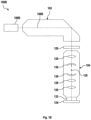
- Fig. 1A shows a schematic view of an EUV lithography apparatus 100A, which comprises a beam shaping and illumination system 102 and a projection system 104.
- EUV stands for "extreme ultraviolet” and denotes a wavelength of the working light of between 0.1 nm and 30 nm.
- the beam shaping and illumination system 102 and the projection system 104 are respectively provided in a vacuum housing (not shown), each vacuum housing being evacuated with the aid of an evacuation device (not shown).
- the vacuum housings are surrounded by a machine room (not shown), in which drive devices for mechanically moving or setting optical elements are provided.
- electrical controllers and the like can also be provided in this machine room.
- the EUV lithography apparatus 100A comprises an EUV light source 106A.
- a plasma source or a synchrotron
- the EUV radiation 108A is focused and the desired operating wavelength is filtered out from the EUV radiation 108A.
- the EUV radiation 108A generated by the EUV light source 106A has a relatively low transmissivity through air, for which reason the beam guiding spaces in the beam shaping and illumination system 102 and in the projection system 104 are evacuated.
- the beam shaping and illumination system 102 illustrated in Fig. 1A has five mirrors 110, 112, 114, 116, 118.
- the EUV radiation 108A is guided onto a photomask (called a reticle) 120.
- the photomask 120 is likewise embodied as a reflective optical element and can be arranged outside the systems 102, 104.
- the EUV radiation 108A can be directed onto the photomask 120 by means of a mirror 122.
- the photomask 120 has a structure which is imaged onto a wafer 124 or the like in a reduced fashion by means of the projection system 104.
- the projection system 104 (also referred to as projection lens) has six mirrors M1 to M6 for imaging the photomask 120 onto the wafer 124.
- individual mirrors M1 to M6 of the projection system 104 can be arranged symmetrically in relation to an optical axis 126 of the projection system 104.
- the number of mirrors M1 to M6 of the EUV lithography apparatus 100A is not restricted to the number represented. A greater or lesser number of mirrors M1 to M6 can also be provided.
- the mirrors M1 to M6 are generally curved on their front face for beam shaping.
- Fig. 1B shows a schematic view of a DUV lithography apparatus 100B, which comprises a beam shaping and illumination system 102 and a projection system 104.
- DUV stands for "deep ultraviolet” and denotes a wavelength of the working light of between 30 nm and 250 nm.
- the beam shaping and illumination system 102 and the projection system 104 can be arranged in a vacuum housing and/or surrounded by a machine room with corresponding drive devices.
- the DUV lithography apparatus 100B has a DUV light source 106B.
- a DUV light source 106B By way of example, an ArF excimer laser that emits radiation 108B in the DUV range at 193 nm, for example, can be provided as the DUV light source 106B.
- the beam shaping and illumination system 102 illustrated in Fig. 1B guides the DUV radiation 108B onto a photomask 120.
- the photomask 120 is embodied as a transmissive optical element and can be arranged outside the systems 102, 104.
- the photomask 120 has a structure which is imaged onto a wafer 124 or the like in a reduced fashion by means of the projection system 104.
- the projection system 104 has a plurality of lens elements 128 and/or mirrors 130 for imaging the photomask 120 onto the wafer 124.
- individual lens elements 128 and/or mirrors 130 of the projection system 104 can be arranged symmetrically in relation to an optical axis 126 of the projection system 104.
- the number of lens elements 128 and mirrors 130 of the DUV lithography apparatus 100B is not restricted to the number represented. A greater or lesser number of lens elements 128 and/or mirrors 130 can also be provided.
- the mirrors 130 are generally curved on their front face for beam shaping.
- An air gap between the last lens element 128 and the wafer 124 can be replaced by a liquid medium 132 which has a refractive index of > 1.
- the liquid medium 132 can be high-purity water, for example. Such a construction is also referred to as immersion lithography and has an increased photolithographic resolution.
- the medium 132 can also be referred to as an immersion liquid.
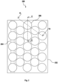
- Fig. 2 shows a plan view of a component 200 for an EUV lithography apparatus 100A as explained above.
- the component 200 can be part of the beam shaping and illumination system 102 or of the projection system 104 of the EUV lithography apparatus 100A.
- the component 200 can also be part of a DUV lithography apparatus 100B as explained above.
- the component 200 can be a so-called Actuation Sensor Unit (ASU), for example, with the aid of which facets of a facet mirror, for example of a field facet mirror or of a pupil facet mirror, can be deflected.
- ASU Actuation Sensor Unit
- Such a facet mirror having deflectable facets can be part of the beam shaping and illumination system 102, for example.
- the component 200 comprises a first component part 202.
- the first component part 202 can be for example a main body or frame of the component 200.
- the first component part 202 can be produced from metal, preferably from copper, high-grade steel or aluminium.
- the first component part 202 is actively cooled. "Actively cooled” should be understood in the present case to mean that a fluid, for example water, is guided through the first component part 202 in order to absorb heat there and transport it away.
- the first component part 202 can comprise a cooling system 204, in particular a cooling circuit, which is illustrated highly schematically in Fig. 2 .
- the cooling system 204 can be formed with the aid of cooling channels provided in the first component part 202.
- the component 200 comprises a multiplicity of second component parts 206, only one of which, however, is provided with a reference sign in Fig. 2 .
- the second component part 206 can be an Actuation Sensor Package (ASP), for example, which is suitable for deflecting a facet of a facet mirror as mentioned above.
- ASP Actuation Sensor Package
- a second component part 206 of this type is assigned to each facet.
- a multiplicity of second component parts 206 are provided.
- hundreds of second component parts 206 can be provided.
- the second component parts 206 are arranged in the shape of a grid or in the shape of a pattern.
- the second component parts 206 can have a circular-cylindrical geometry.
- the second component parts 206 are received in the first component part 202 at least in sections and are sealed vis-à-vis said first component part.
- the second component parts 206 can be cooled with the aid of the cooling system 204.
- the first component part 202 has receiving sections, for example holes or recesses, in which the second component parts 206 are received in sections.
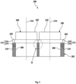
- Fig. 3 shows a schematic section view through two second component parts 206 in accordance with the sectional line III-III in Fig. 2 .
- Fig. 4 shows the detail view IV in accordance with Fig. 3 . Reference is made below to Figs 3 and 4 simultaneously.
- the first component part 202 comprises receiving sections 208, in which the second component parts 206 are received.
- the receiving sections 208 can be embodied as holes in the first component part 202.
- the first component part 202 furthermore comprises one sealing surface 210 or a plurality of sealing surfaces 210.
- a sealing surface 210 of this type is assigned to each second component part 206.
- the sealing surfaces 210 each extend circularly around the corresponding second component part 206.
- the second component parts 206 each project above the sealing surface 210 assigned thereto.
- Each second component part 206 comprises a main body 212 having a cylindrical base section 214 and a flange section 216 extending around the base section 214.
- the base section 214 can be constructed rotationally symmetrically with respect to a centre axis or axis of symmetry 218.
- the flange section 216 is not constructed rotationally symmetrically with respect to the axis of symmetry 218.
- the flange section 216 can be polygonal. As viewed along the sectional line III-III, a distance A1 between flange sections 216 of two adjacent second component parts 206 is only a few hundred ⁇ m. By way of example, the distance A1 can be 200 ⁇ m.
- the base section 214 is received in the receiving section 208 and projects beyond the corresponding sealing surface 210.
- the flange section 216 comprises in each case a sealing surface 220 respectively facing a corresponding sealing surface 210 of the first component part 202.
- a ring body 222 is placed onto the main body 212.
- the ring body 222 is closed off with a ceramic plate towards the top in the orientation in Fig. 3 .
- the ceramic plate can be soldered into the ring body 222.
- the ring body 222 can be welded to the main body 212.
- Each second component part 206 comprises a sensor system and an actuator.
- the actuator can comprise a plurality of coils.
- the second component parts 206 are sealed vis-à-vis the first component part 202, in particular the sealing surfaces 210, with the aid of a sealing device 300.
- the sealing device 300 is positioned and pressed between the sealing surfaces 210, 220.
- a yielding volume 226 for the pressing of the sealing device 300 is provided in each case between the sealing device 300 and the base sections 214.
- the yielding volume 226 can be referred to as a compensation volume.
- Fig. 5 shows a schematic sectional view through two second component parts 206 in accordance with the sectional line V-V in Fig. 2 .
- Fig. 6 shows the detail view VI in accordance with Fig. 5 . Reference is made below to Figs 5 and 6 simultaneously.
- the first component part 202 extends out over the sealing surfaces 210 with a bearing section 224.
- the second component parts 206 bear on the bearing sections 224 in such a way that the sealing surfaces 210, 220 are positioned at a defined distance away from one another.
- the distance A1 is significantly larger when viewed along the sectional line V-V than when viewed along the sectional line III-III.
- the ridge-shaped bearing section 224 is provided between two adjacent second component parts 206, the flange sections 216 of the second component parts 206 being supported on said bearing section.
- the sealing device 300 extends between the bearing section 224 and the base sections 214 of the main body 212 of the respective second component part 206. Significantly more structural space is present between adjacent second component parts 206 in comparison with a view along the sectional line III-III. There is a significantly larger overlap between the sealing surfaces 220 of the second component parts 206 and the sealing device 300. Therefore, a decentration of the sealing device 300 is rather noncritical here with regard to leaks.
- the yielding volume 226 for the pressing of the sealing device 300 is also significantly larger as viewed along the sectional line V-V.
- an internal diameter of the sealing device 300 is then increased in order to enlarge the yielding volume 226, the centring of the sealing device 300 is no longer ensured, however.
- the lack of centring of the sealing device 300 can have the effect that in the view along the sectional line III-III the sealing device 300 bears against one of two adjacent second component parts 206 and is spaced apart by double the distance from the other of the two second component parts 206. Leaks can occur on account of the small overlap between the sealing surface 220 and the sealing device 300. No overlap at all between the sealing surface 220 and the sealing device 300 occurs in the worst case. This must be avoided.
- the small structural space between the second component parts 206 does not permit the sealing device 300 to be separated into individual sealing rings, for example into O-rings. Furthermore, individual sealing rings cannot be prevented from tilting away on account of the small structural space. Therefore, the sealing device 300, as shown in Fig. 7 , is produced as a sealing mat, which is cut out from a suitable plastics material with the aid of a laser, for example.
- a perfluoro rubber (FFKM) can be used as suitable material.
- the sealing device 300 comprises a multiplicity of sealing rings 302 connected to one another, only one of which, however, is provided with a reference sign in Fig. 7 .
- the sealing rings 302 are connected to one another, the sealing rings 302 are prevented from tilting away.
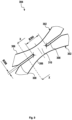
- Fig. 8 shows the detail view IIX in accordance with Fig. 7 .
- the sealing rings 302 are connected to one another at connection locations 304, only two of which are provided with a reference sign in Fig. 8 .
- the sealing device 300 is thus an integral component part, in particular one which is materially in one piece.
- “Integral” should be understood to mean in the present case that the sealing device 300 forms a single component part, which is not constructed from mutually separate component parts. That is to say that the sealing rings 302 are fixedly connected to one another, wherein the totality of all the sealing rings 302 forms the sealing device 300.
- “Materially in one piece” should be understood in the present case to mean that the sealing device 300 is an integral component part produced from the same material throughout.
- the sealing rings 302 each have an external diameter DA, which is constant and which is flattened only in the region of the connection locations 304.
- DA external diameter
- the sealing rings 302 are embodied such that they each also have a constant internal diameter chosen in such a way that a centring on the respective base section 214 of the second component parts 206 is effected, the problem arises that, as viewed along the sectional line III-III in Fig. 2 , almost no yielding volume 226 for the pressing of the sealing device 300 is present. Consequently, the sealing device 300 cannot be pressed sufficiently between adjacent second component parts 206.
- the sealing rings 302 each comprise an inner contour 306 which is not circular, but rather, as will be explained below, is trefoiled. That is to say that the sealing rings 302 have a varying internal diameter rather than a constant internal diameter.
- a theoretical internal diameter DI of the sealing ring 302 is illustrated by a dashed line in Fig. 8 .
- the internal diameter DI corresponds to an external diameter of the base section 214 of the second component parts 206.
- Each sealing ring 302 comprises a first plane of symmetry E1 and a second plane of symmetry E2.
- the planes of symmetry E1, E2 are positioned perpendicularly to one another and intersect one another.
- the sealing ring 302 is constructed symmetrically, in particular mirror-symmetrically, both with respect to the first plane of symmetry E1 and with respect to the second plane of symmetry E2.
- the diameters DA, DI have their centre point on a line of intersection of the two planes of symmetry E1, E2.
- a coordinate system having a first spatial direction or x-direction x, a second spatial direction or y-direction y and a third spatial direction or z-direction z is assigned to the sealing ring 302.
- the directions x, y, z are positioned perpendicularly to one another.
- an azimuth direction or circumferential direction U is also assigned to the sealing ring 302.
- the circumferential direction U can be oriented in the clockwise or anticlockwise direction.
- the circumferential direction U is oriented in the anticlockwise direction in Fig. 8 .
- the circumferential direction U runs along the inner contour 306.
- connection locations 304 are arranged mirror-symmetrically both with respect to the first plane of symmetry E1 and with respect to the second plane of symmetry E2.
- a respective azimuth angle ⁇ , ⁇ is provided between two adjacent connection locations 304.
- the azimuth angle ⁇ can be referred to as first azimuth angle.
- the azimuth angle ⁇ can be referred to as second azimuth angle.
- the azimuth angle ⁇ is greater than the azimuth angle ⁇ .
- the azimuth angle ⁇ is approximately 71° and the azimuth angle ⁇ is approximately 108°.
- the azimuth angle ⁇ is provided in each case between two connection locations 304 arranged mirror-symmetrically with respect to the first plane of symmetry E1.
- the azimuth angle ⁇ is provided in each case between two connection locations 304 arranged mirror-symmetrically with respect to the second plane of symmetry E2.
- the sealing ring 302 comprises a connection radius R304 at the connection locations 304.
- the inner contour 306 thus has the connection radius R304 in the region of the connection locations 304. That is to say that four connection radii R304 are provided, only one of which, however, is shown in Fig. 8 .
- a respective centre point MR304-1 to MR304-4 of the connection radius R304 lies outside the planes of symmetry E1, E2.
- Four centre points MR304-1 to MR304-4 are provided, which lie on lines of symmetry L1 to L3 of the connection locations 304.
- Each connection location 304 is assigned a line of symmetry L1 to L3, wherein only three lines of symmetry L1 to L3 are shown in Fig. 8 .
- connection locations 304 are constructed in each case symmetrically with respect to the lines of symmetry L1 to L3. In other words, the lines of symmetry L1 to L3 run centrally through the connection locations 304.
- the azimuth angles ⁇ , ⁇ are plotted between the lines of symmetry L1 to L3.
- the centre points MR304-1 to MR304-4 are positioned mirror-symmetrically with respect to the planes of symmetry E1, E2.
- the centre points MR304-1, MR304-4 and the centre points MR304-2, MR304-3 are positioned in a manner spaced apart by a distance A2 from one another in the y-direction y.
- the centre points MR304-1, MR304-2 and the centre points MR304-3, MR304-4 are positioned in a manner spaced apart by a distance A3 from one another in the x-direction x.
- the distance A2 is greater than the distance A3.
- the respective connection radius R304 extends over an azimuth angle ⁇ in the circumferential direction U.
- the azimuth angle ⁇ is 20°, for example.
- the distances A2, A3 are equal in magnitude.
- the connection radius R304 is less than half the internal diameter DI.
- the inner contour 306 has a respective first intermediate radius R11, R12 between two connection locations 304 which are adjacent in the x-direction x.
- the inner contour 306 comprises two first intermediate radii R11, R12.
- the first intermediate radii R11, R12 are situated respectively at the top and bottom in the orientation in Fig. 8 .
- the first intermediate radii R11, R12 are each greater than the connection radius R304. It thus holds true that: R11, R12 > R304.
- a respective centre point MR11, MR12 of the first intermediate radii R11, R12 is situated on the first plane of symmetry E1 and is offset respectively upwards and downwards in relation to the second plane of symmetry E2 in the orientation in Fig. 8 .
- the centre points MR11, MR12 of the first intermediate radii R11, R12 are positioned in a manner spaced apart by a distance A4 from one another.
- the centre point MR11 is assigned to the first intermediate radius R11.
- the centre point MR12 is assigned to the first intermediate radius R12.
- the inner contour 306 comprises a respective second intermediate radius R21, R22 between two connection locations 304 which are adjacent in the y-direction y.
- the inner contour 306 comprises two second intermediate radii R21, R22.
- the second intermediate radii R21, R22 are situated respectively on the left and right in the orientation in Fig. 8 .
- the second intermediate radii R21, R22 are in each case greater than the connection radius R304 and less than the first intermediate radii R11, R12. It thus holds true that: R 11, R12 > R21, R22 > R304. However, other suitable size relationships can also be chosen.
- the intermediate radii R11, R12, R21, R22 are greater than half the internal diameter DI.
- a respective centre point MR21, MR22 of the second intermediate radii R21, R22 is situated on the second plane of symmetry E2 and is offset respectively towards the left and right in relation to the first plane of symmetry E1 in the orientation in Fig. 8 .
- the centre points MR21, MR22 of the second intermediate radii R21, R22 are positioned in a manner spaced apart by a distance A5 from one another.
- the centre point MR21 is assigned to the second intermediate radius R21.
- the centre point MR22 is assigned to the second intermediate radius R22.
- the distance A4 is greater than the distance A5.
- the distances A4, A5 are equal in magnitude. Accordingly, the intermediate radii R11, R12, R21, R22 can also be equal in magnitude.
- the inner contour 306 furthermore comprises optional transition radii RU, with the aid of which the intermediate radii R11, R12, R21, R22 transition into the respective connection radius R304.
- transition radii RU are provided per connection location 304.
- the transition radii RU are preferably identical, but can also be embodied individually.
- the transition radii RU provide for a continuously variable transition from the respective connection radius R304 into the intermediate radii R11, R12, R21, R22.
- the prestress of the sealing ring 302 on the base section 214 of the respective second component part 206 is proportional to the azimuth angle ⁇ , ⁇ .
- ⁇ azimuth angle
- ⁇ azimuth angle
- connection radius R304 in the region of the connection locations 304, said connection radius being chosen such that it is less than the external diameter of the base section 214 of the second component parts 206 and thus the internal diameter DI, a sufficiently large yielding volume 226 for the pressing of the sealing ring 302 can be provided at the connection locations 304.
- the inner contour 306 experiences a constriction or narrowing, such that the inner contour 306 bears against the base section 214 and can be centred there. Consequently, between the connection locations 304, the inner contour 306 bears against the base section 214 with a prestress.
- the narrowing of the inner contour 306 between the connection locations 304 and the widening of said inner contour at the connection locations 304 result in the inner contour 306 having the trefoiled or trefoil-like design mentioned above.
- Fig. 9 shows the detail view IV in accordance with Fig. 7.
- Fig. 7 shows a connection location 304 between two sealing rings 302 in detail.
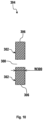
- a respective yielding volume 308 is provided at the connection location 304 on both sides, said yielding volume, like the yielding volume 226, enabling the sealing rings 302 to be pressed.
- the yielding volume 308 can be referred to as a compensating volume. Unlike the yielding volume 226, however, the yielding volumes 308 are provided directly at the sealing device 300.
- a connection web 310 is provided between the yielding volumes 308, said connection web connecting adjacent sealing rings 302 to one another integrally.
- the connection location 304 itself has a width B304 at the connection web 310.
- the width B304 can be two millimetres, for example.
- the yielding volumes 308 can be embodied as flattened portions of the respective external diameter DA of the sealing rings 302. That is to say that the external diameters DA of adjacent sealing rings 302 do not transition into one another.
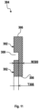
- the yielding volumes 308 are embodied in each case as a cutout or groove extending completely through a wall thickness W300 ( Fig. 10 ) of the sealing device 300.
- the groove-type yielding volumes 308 can have a width B308.
- the width B308 can be for example 0.1 to 0.3, in particular 0.2, millimetre.
- the wall thickness W300 can be 1 to 3, in particular 2, millimetres.
- Fig. 11 shows a development of the connection location 304 explained with reference to Figs 9 and 10 .
- the yielding volumes 308 do not extend completely through the wall thickness W300, but rather only to a depth T308.
- the depth T308 can be 1 millimetre, for example.
- Fig. 12 shows once again the detail view IV in accordance with Fig. 7 , but a development of the connection location 304 shown in Figs 9 and 10 is illustrated in Fig. 12 .
- the yielding volumes 308 are not embodied as cutouts or grooves. Rather, the yielding volumes 308 comprise a multiplicity of holes 312, 314, 316 positioned next to one another, only three of which, however, are provided with a reference sign in Fig. 12 .
- the number of holes 312, 314, 316 is arbitrary. By way of example, it is possible to provide six holes 312, 314, 316 of this type per yielding volume 308.
- the holes 312, 314, 316 can be circular and have a diameter D308 in each case. However, the holes 312, 314, 316 can also have any other geometry. By way of example, the holes 312, 314, 316 can also be oval or polygonal. The diameter D308 can be 0.2 millimetre, for example. The holes 312, 314, 316 can all have the same diameter D308 or mutually different diameters D308. The holes 312, 314, 316 can be arranged in one row, as shown in Fig. 12 . Alternatively, the holes 312, 314, 316 can also be arranged in a plurality of rows. The holes 312, 314, 316 can be positioned in a manner spaced apart from one another uniformly or non-uniformly.
- connection location 304 itself, as shown in Fig. 12 , along the width B304, that is to say at the connection web 310, can be free of holes 312, 314, 316 or hole-free or holeless.
- the holes 312, 314, 316 can extend through the entire wall thickness W300 or only to the depth T308 explained above.
- Fig. 13 shows once again the detail view IV in accordance with Fig. 7 , but a development of the connection location 304 shown in Fig. 12 is illustrated in Fig. 13 .
- the yielding volumes 308 each comprise a plurality of rows 318, 320 of holes, which in turn have a multiplicity of holes 312, 314, 316 as explained above.
- the number of rows 318, 320 of holes is arbitrary.
- the holes 312, 314, 316 can be arranged in two rows, as shown in Fig. 13 . However, the holes 312, 314, 316 can also be arranged in three rows or in four rows.
- the individual holes 312, 314, 316 of the rows 318, 320 of holes can be positioned next to one another, as shown in Fig. 13 . However, the holes 312, 314, 316 can also be arranged offset with respect to one another.
- Fig. 14 shows once again the detail view IV in accordance with Fig. 7 , but a development of the connection location 304 shown in Fig. 12 is illustrated in Fig. 14 .
- the entire connection web 310 is provided with holes 312, 314, 316, such that only a single continuous yielding volume 308 formed from holes 312, 314, 316 is provided.
Landscapes
- Engineering & Computer Science (AREA)
- Physics & Mathematics (AREA)
- General Physics & Mathematics (AREA)
- Health & Medical Sciences (AREA)
- Environmental & Geological Engineering (AREA)
- Epidemiology (AREA)
- Public Health (AREA)
- General Engineering & Computer Science (AREA)
- Microelectronics & Electronic Packaging (AREA)
- Mechanical Engineering (AREA)
- Exposure And Positioning Against Photoresist Photosensitive Materials (AREA)
- Gasket Seals (AREA)
Description
- The present invention relates to a sealing device for a lithography apparatus, to a component for a lithography apparatus comprising a sealing device of this type, and to a lithography apparatus comprising a sealing device of this type and/or a component of this type.
- Microlithography is used for producing microstructured components, for example integrated circuits. The microlithography process is performed using a lithography apparatus, which has an illumination system and a projection system. The image of a mask (reticle) illuminated by means of the illumination system is in this case projected by means of the projection system onto a substrate (for example a silicon wafer) which is coated with a light-sensitive layer (photoresist) and arranged in the image plane of the projection system, in order to transfer the mask structure to the light-sensitive coating of the substrate.
- Driven by the desire for ever smaller structures in the production of integrated circuits, currently under development are EUV lithography apparatuses that use light with a wavelength in the range from 0.1 nm to 30 nm, in particular 13.5 nm. In the case of such EUV lithography apparatuses, because of the high absorption of light of this wavelength by most materials, reflective optical units, that is to say mirrors, have to be used instead of - as previously - refractive optical units, that is to say lens elements.
- An EUV lithography apparatus as explained above comprises components having a cooling circuit, for example for cooling the respective component with water, or a purging circuit, for example for purging the respective component with a purge gas, in particular with an inert gas. A component of this type can be a so-called actuation sensor unit, for example, with the aid of which facets of a facet mirror, for example of a field facet mirror or of a pupil facet mirror, can be deflected. In this case, a so-called actuation sensor package is assigned to each facet for the purpose of deflecting the facets. The actuation sensor packages should be sealed in a fluid-tight manner vis-à-vis a main body or frame of the actuation sensor unit.
- For sealing purposes, O-rings or sealing mats can be used as seals. In order to maintain the sealing function during operation and over the lifetime, the seal can be clamped onto the respective actuation sensor package by means of prestress or in a manner supported in the pressure direction. A centring of the seal can be obtained as a result. In this case, it should be taken into consideration that the seal requires a yielding volume for the purpose of pressing it. Said yielding volume can be created by keeping enough space available between an inner contour of the respective seal and the actuation sensor package. However, this space is in turn disadvantageous with regard to a good centring of the seal. For instance,
US 2017/108788 A1 discloses a facet mirror comprising a multiplicity of sealing rings. - Against this background, it is an object of the present invention to provide an improved sealing device.
- In accordance with claim 1, a sealing device for sealing a first component part of a lithography apparatus vis-à-vis a multiplicity of second component parts of the lithography apparatus is proposed. The sealing device comprises a multiplicity of sealing rings, and a multiplicity of connection locations, wherein the sealing rings are integrally connected to one another with the aid of the connection locations.
- By virtue of the fact that the sealing rings are connected to one another with the aid of the connection locations, the mounting of the sealing device is simplified compared to a sealing device without such connection locations.
- The sealing device can also be referred to as a sealing mat. Preferably, a multiplicity of sealing rings is provided which form a two-dimensional pattern or grid. That is to say that the sealing rings are arranged in particular in the shape of a grid or in the shape of a pattern. A plurality of connection locations, for example four, are assigned to each sealing ring. The connection locations can also be referred to as contact locations. In accordance with the invention, the sealing rings are connected to one another integrally, in particular materially in one piece, with the aid of the connection locations. "Integrally" means in the present case that the sealing rings together form a common component part, namely the sealing device. "Materially in one piece" means here that the sealing device is produced from the same material throughout. Preferably, the sealing device is produced from a plastics material. By way of example, a perfluoro rubber (FFKM) can be used as suitable material. The sealing device can be cut out from a sheet or film of a suitable plastics material with the aid of a laser, for example.
- In accordance with one embodiment, the connection locations each comprise a yielding volume for pressing the respective sealing ring between the first component part and one of the second component parts.
- By virtue of the fact that the yielding volume is provided, it is possible for the respective sealing ring always to be sufficiently pressed, with the result that leaks during mounting and also over the service life of the lithography apparatus can be prevented or at least significantly reduced. The yielding volume can be provided between an inner contour of the respective sealing ring and a second component part received in the inner contour. However, the yielding volume can also be provided directly in or at the respective connection location, for example in the form of a cutout, a groove, a hole or the like. All that is relevant here is that material of the sealing ring is pressed into the yielding volume during the pressing of the respective sealing ring. The abovementioned inner contour of the sealing ring can have an arbitrary shape. The inner contour can be circular, oval, triangular, polygonal or the like. Furthermore, the inner contour - as will be explained below - can also be trefoiled. The yielding volume is provided in particular in or at the sealing device itself.
- In accordance with a further embodiment, each sealing ring comprises an inner contour, in each of which a second component part is able to be received at least in sections, and wherein the yielding volume is formed by virtue of the inner contour widening at the connection locations.
- The fact that the inner contour "widens" means in the present case that the inner contour, at least in an unpressed state of the respective sealing ring, does not bear against the corresponding second component part and thus stands away from the second component part, in particular. By virtue of the fact that the inner contour widens at the connection locations, a sufficiently large yielding volume for the pressing of the respective sealing ring can be provided at the connection locations.
- In accordance with a further embodiment, the inner contour comprises a connection radius at the connection locations, wherein the inner contour comprises an intermediate radius in each case between two adjacent connection locations, and wherein the intermediate radius and the connection radius differ from one another in terms of their absolute value in such a way that the inner contour widens at the connection locations and narrows between two adjacent connection locations.
- By virtue of the fact that the inner contour narrows between two adjacent connection locations, a centring of the sealing rings at the respective intermediate radius is made possible. Thus, with the aid of the widening and the narrowing, it is possible simultaneously to ensure a sufficiently large yielding volume for the pressing of the sealing rings and a centring of the sealing rings at the second component parts.
- In accordance with one preferred embodiment of the sealing device, the latter comprises a multiplicity of sealing rings, a multiplicity of connection locations, wherein the sealing rings are connected to one another with the aid of the connection locations, wherein each sealing ring comprises an inner contour, in each of which a second component part is able to be received at least in sections, wherein the inner contour comprises a connection radius at the connection locations, wherein the inner contour comprises an intermediate radius in each case between two adjacent connection locations, and wherein the intermediate radius and the connection radius differ from one another in terms of their absolute value in such a way that the inner contour widens at the connection locations and narrows between two adjacent connection locations.
- The inner contour is composed of a plurality of radii, in particular. That is to say that the inner contour is preferably not circular. The inner contour can also have any other geometry, as mentioned above. In the region of the connection locations, the inner contour has a widening or broadening and, in the region between the connection locations, the inner contour has a narrowing, constriction or restriction. This results in a trefoiled or trefoil-like geometry of the inner contour, deviating from the circular shape. The inner contour can therefore be referred to as "trefoiled" or "trefoil-like". The sealing device is positioned in particular between a sealing surface of the first component part and a sealing surface of the second component part and effects fluid-tight sealing vis-à-vis them.
- The fact that the second component part is "able to be received" in the inner contour should be understood in the present case to mean that a respective sealing ring can be put onto the second component part, or vice versa. In this case, the second component part preferably has a circular-cylindrical base section, at which the sealing ring is centred with the aid of the intermediate radius.
- Preferably, as mentioned above, four connection locations are provided. Accordingly, the inner contour also has four times the connection radius and four times the intermediate radius. Accordingly, there are, in particular, also four pairs of adjacent connection locations, between each of which a connection radius is provided. The radii transition into one another, such that the inner contour has no shoulders, but rather a curved shape.
- The fact that the intermediate radius and the connection radius "differ" from one another should be understood to mean, in particular, that the intermediate radius is greater than the connection radius, or vice versa. A centre point of the connection radius can be offset relative to a centre point of the intermediate radius in such a way that the condition that the inner contour widens at the connection locations and narrows between two adjacent connection locations is met both if the connection radius is greater than the intermediate radius and if the connection radius is less than the intermediate radius.
- In accordance with a further embodiment, the intermediate radius is greater than the connection radius.
- By way of example, the connection radius is approximately 5 mm. The intermediate radius can be approximately 11 to 12 mm.
- In accordance with a further embodiment, the inner contour comprises a first intermediate radius and a second intermediate radius, wherein the first intermediate radius and the second intermediate radius are equal in magnitude or have different magnitudes.
- Preferably, the first intermediate radius is greater than the second intermediate radius. Alternatively, the first intermediate radius can also be less than the second intermediate radius. With the aid of the different intermediate radii, it is possible, if the connection locations are positioned in a manner spaced apart from one another at different azimuth angles in an azimuth direction or circumferential direction, to take account of the fact that a shortening of the sealing ring by the factor of azimuth angle/360° is to be produced between two connection locations in order, during the mounting of the sealing device, to prevent the connection locations from moving azimuthally, which could otherwise lead to warpage of the sealing device. For the case where the azimuth angles are equal in magnitude, the first intermediate radius and the second intermediate radius are preferably also equal in magnitude. Preferably, the connection locations are constructed in each case symmetrically with respect to a line of symmetry assigned to the respective connection location. The azimuth angles are measured between the lines of symmetry of the connection locations. A respective centre point of the connection radius lies on the line of symmetry of that connection location to which the connection radius is assigned.
- In accordance with a further embodiment, the second intermediate radius has a bigger magnitude than the first intermediate radius.
- Alternatively, the second intermediate radius can also have a smaller magnitude than the first intermediate radius.
- In accordance with a further embodiment, two adjacent connection locations between which the first intermediate radius is provided and two adjacent connection locations between which the second intermediate radius is provided are arranged in a manner spaced apart at the same distance or at different distances from one another.
- Preferably, the connection locations are positioned in a manner spaced apart from one another non-uniformly as viewed in the circumferential direction. That is to say that different azimuth angles are provided between the connection locations. In this case, the first intermediate radius is positioned between a pair of connection locations between which a smaller azimuth angle is provided. The second intermediate radius is provided between a pair of connection locations between which a larger azimuth angle is provided. For the case where the azimuth angles are equal in magnitude, the connection locations are also arranged in a manner spaced apart at an equal distance from one another.
- In accordance with a further embodiment, a centre point of the intermediate radius is arranged offset relative to a centre point of the connection radius.
- Preferably, the sealing ring comprises a first plane of symmetry and a second plane of symmetry, with respect to which the sealing ring is constructed symmetrically. The planes of symmetry are positioned perpendicularly to one another, in particular. The centre point of the intermediate radius is positioned eccentrically. The centre point of the connection radius is also positioned eccentrically. As mentioned above, the centre point of the connection radius lies on the respective line of symmetry of the connection location.
- In accordance with a further embodiment, a centre point of the first intermediate radius is arranged offset relative to the centre point of the connection radius in an x-direction and a y-direction of the sealing ring, wherein a centre point of the second intermediate radius is arranged offset relative to the centre point of the connection radius in the x-direction and in the y-direction of the sealing ring.
- In particular, a coordinate system having a first spatial direction or x-direction, a second spatial direction or y-direction and a third spatial direction or z-direction is assigned to the sealing ring. The spatial directions are positioned perpendicularly to one another. The first plane of symmetry is spanned by the y-direction and the z-direction, in particular. The second plane of symmetry is spanned by the x-direction and the z-direction, in particular. The inner contour runs in particular as two-dimensional geometry in the x-direction and the y-direction. The centre point of the first intermediate radius is positioned offset relative to the centre point of the connection radius in the x-direction and the y-direction in particular in such a way that the inner contour experiences a constriction in the region of the first intermediate radius, even though the first intermediate radius is greater than the connection radius. In particular, the centre point of the second intermediate radius is positioned offset relative to the centre point of the connection radius in the x-direction and in the y-direction in such a way that the inner contour experiences a constriction in the region of the second intermediate radius, even though the second intermediate radius is preferably greater than the connection radius.
- In accordance with a further embodiment, centre points of two first intermediate radii are arranged in a manner spaced apart from one another by a first distance in the y-direction, wherein centre points of two second intermediate radii are arranged in a manner spaced apart from one another by a second distance in the x-direction, and wherein the first distance and the second distance are equal in magnitude or have different magnitudes.
- In particular, the centre points of the two first intermediate radii are positioned in the first plane of symmetry and outside the second plane of symmetry. Preferably, the centre points are positioned mirror-symmetrically with respect to the second plane of symmetry. In particular, the centre points of the two second intermediate radii are positioned in the second plane of symmetry and outside the first plane of symmetry. Preferably, the centre points of the second intermediate radii are positioned mirror-symmetrically with respect to the first plane of symmetry. For the case where the azimuth angles are equal in magnitude, the first distance and the second distance are preferably equal in magnitude.
- In accordance with a further embodiment, the first intermediate radii and the second intermediate radii are arranged alternating along the inner contour.
- This means that seen along the inner contour, each first intermediate radius is arranged between two second intermediate radii and vice versa. The two first intermediate radii are arranged vis-á-vis or with a peripheral angle of 180°. The same can be valid for the second intermediate radii.
- In accordance with a further embodiment, the inner contour comprises a transition radius, wherein the intermediate radius transitions into the connection radius with the aid of the transition radius.
- This ensures a continuously variable transition from the intermediate radius to the transition radius. Preferably, the transition radius is less than the intermediate radius and the connection radius.
- In accordance with a further embodiment, two yielding volumes are provided per connection location, wherein a connection web of the connection location is provided between the two yielding volumes, and wherein the connection web connects adjacent sealing rings to one another.
- In particular, the connection web connects the sealing rings to one another integrally, in particular materially in one piece.
- In accordance with a further embodiment, the yielding volume is a groove which completely penetrates through a wall thickness of the sealing device or which extends only to a defined depth into the wall thickness.
- For the case where the groove penetrates through the wall thickness only to the defined depth, the groove can be rectangular or rounded in cross section. If the groove does not completely penetrate through the wall thickness, said groove can also extend through the connection web. The groove can comprise sidewalls running parallel to one another. The sidewalls can also be positioned obliquely with respect to one another, such that the groove is wedge-shaped.
- In accordance with a further embodiment, the yielding volume comprises a multiplicity of holes which completely penetrate through a wall thickness of the sealing device or which extend only to a defined depth into the wall thickness.
- The holes can all have the same diameter or different diameters. The holes can be arranged in a manner spaced apart from one another uniformly or non-uniformly. The holes can be arranged in one row or a plurality of rows.
- Furthermore, a component for a lithography apparatus is proposed. The component comprises a first component part, a multiplicity of second component parts which are received at least in sections in the first component part, and a sealing device of this type.
- By way of example, the component can be part of a beam shaping and illumination system or of a projection system of the lithography apparatus. The component can be a so-called Actuation Sensor Unit (ASU), for example, with the aid of which facets of a facet mirror, for example of a field facet mirror or of a pupil facet mirror, can be deflected. Such a facet mirror having deflectable facets can be part of the beam shaping and illumination system, for example. The first component part can be for example a main body or frame of the component. The first component part can comprise a cooling system for cooling the component, in particular the second component parts. The cooling system can be formed with the aid of cooling channels provided in the first component part. The second component part can be an Actuation Sensor Package (ASP), for example, which is suitable for deflecting a facet of a facet mirror as mentioned above. The second component parts can have a circular-cylindrical geometry at least in sections. With the aid of the sealing device, the second component parts are sealed vis-à-vis the first component part in order to seal the cooling system with respect to surroundings of the component.
- In accordance with one embodiment, the sealing rings are pressed in each case between the first component part and one of the second component parts in such a way that a respective yielding volume of the sealing device is at least partly filled with material of the respective sealing ring.
- During the pressing of the sealing ring, the latter is pressed at least partly into the yielding volume. A permanent safeguard against leaks is achieved as a result.
- In accordance with one preferred embodiment, the component comprises a first component part, a multiplicity of second component parts which are received in the first component part at least in sections, a sealing device as explained above, wherein the inner contour, for the purpose of centring the respective sealing ring at one of the second component parts, bears against the second component part with the intermediate radius, and wherein the inner contour, for the purpose of providing a yielding volume between the inner contour and the second component part, stands away from the second component part at the connection radius.
- The fact that the inner contour "stands away" from the second component part at the connection radius for the purpose of providing the yielding volume should be understood to mean, in particular, that the inner contour does not make contact with the second component part in the region of the connection radius. That is to say that the inner contour and the second component part are free of contact or do not touch at the connection radius.
- Furthermore, a lithography apparatus is proposed. The lithography apparatus concomitantly comprises a sealing device as explained above and/or a component as explained above.
- The lithography apparatus can be an EUV lithography apparatus or a DUV lithography apparatus. EUV stands for "extreme ultraviolet" and denotes a wavelength of the working light of between 0.1 nm and 30 nm. DUV stands for "deep ultraviolet" and denotes a wavelength of the working light of between 30 nm and 250 nm.
- "A(n); one" in the present case should not necessarily be understood as restrictive to exactly one element. Rather, a plurality of elements, such as, for example, two, three or more, can also be provided. Any other numeral used here, too, should not be understood to the effect that there is a restriction to exactly the stated number of elements. Rather, numerical deviations upwards and downwards are possible, unless indicated to the contrary.
- The embodiments and features described for the sealing device are correspondingly applicable to the proposed component and respectively to the proposed lithography apparatus, and vice versa.
- Further advantageous configurations and aspects of the invention are the subject matter of the dependent claims and also of the exemplary embodiments of the invention described below. In the text that follows, the invention is explained in more detail on the basis of preferred embodiments and with reference to the accompanying figures.
-
Fig. 1A shows a schematic view of one embodiment of an EUV lithography apparatus; -
Fig. 1B shows a schematic view of one embodiment of a DUV lithography apparatus; -
Fig. 2 shows a schematic view of one embodiment of a component for the lithography apparatus in accordance withFig. 1A orFig. 1B ; -
Fig. 3 shows a schematic sectional view of the component in accordance with the sectional line III-III inFig. 2 ; -
Fig. 4 shows the detail view IV in accordance withFig. 3 ; -
Fig. 5 shows a further schematic sectional view of the component in accordance with the sectional line V-V inFig. 2 ; -
Fig. 6 shows the detail view VI in accordance withFig. 5 ; -
Fig. 7 shows a schematic view of one embodiment of a sealing device for the component in accordance withFig. 2 ; -
Fig. 8 shows the detail view IIX in accordance withFig. 7 ; -
Fig. 9 shows the detail view IX in accordance withFig. 7 ; -
Fig. 10 shows a schematic sectional view of the sealing device in accordance with the sectional line X-X inFig. 9 ; -
Fig. 11 shows a schematic sectional view of a further embodiment of a sealing device for the component in accordance withFig. 2 ; -
Fig. 12 shows a schematic detail view of a further embodiment of a sealing device for the component in accordance withFig. 2 ; -
Fig. 13 shows a schematic detail view of a further embodiment of a sealing device for the component in accordance withFig. 2 ; and -
Fig. 14 shows a schematic detail view of a further embodiment of a sealing device for the component in accordance withFig. 2 . - Identical elements or elements having an identical function have been provided with the same reference signs in the figures, unless indicated to the contrary. It should also be noted that the illustrations in the figures are not necessarily true to scale.
-
Fig. 1A shows a schematic view of anEUV lithography apparatus 100A, which comprises a beam shaping andillumination system 102 and aprojection system 104. In this case, EUV stands for "extreme ultraviolet" and denotes a wavelength of the working light of between 0.1 nm and 30 nm. The beam shaping andillumination system 102 and theprojection system 104 are respectively provided in a vacuum housing (not shown), each vacuum housing being evacuated with the aid of an evacuation device (not shown). The vacuum housings are surrounded by a machine room (not shown), in which drive devices for mechanically moving or setting optical elements are provided. Moreover, electrical controllers and the like can also be provided in this machine room. - The
EUV lithography apparatus 100A comprises an EUVlight source 106A. A plasma source (or a synchrotron), which emitsradiation 108A in the EUV range (extreme ultraviolet range), that is to say for example in the wavelength range of 5 nm to 20 nm, can for example be provided as the EUVlight source 106A. In the beam shaping andillumination system 102, theEUV radiation 108A is focused and the desired operating wavelength is filtered out from theEUV radiation 108A. TheEUV radiation 108A generated by the EUVlight source 106A has a relatively low transmissivity through air, for which reason the beam guiding spaces in the beam shaping andillumination system 102 and in theprojection system 104 are evacuated. - The beam shaping and
illumination system 102 illustrated inFig. 1A has fivemirrors illumination system 102, theEUV radiation 108A is guided onto a photomask (called a reticle) 120. Thephotomask 120 is likewise embodied as a reflective optical element and can be arranged outside thesystems EUV radiation 108A can be directed onto thephotomask 120 by means of amirror 122. Thephotomask 120 has a structure which is imaged onto awafer 124 or the like in a reduced fashion by means of theprojection system 104. - The projection system 104 (also referred to as projection lens) has six mirrors M1 to M6 for imaging the
photomask 120 onto thewafer 124. In this case, individual mirrors M1 to M6 of theprojection system 104 can be arranged symmetrically in relation to anoptical axis 126 of theprojection system 104. It should be noted that the number of mirrors M1 to M6 of theEUV lithography apparatus 100A is not restricted to the number represented. A greater or lesser number of mirrors M1 to M6 can also be provided. Furthermore, the mirrors M1 to M6 are generally curved on their front face for beam shaping. -
Fig. 1B shows a schematic view of aDUV lithography apparatus 100B, which comprises a beam shaping andillumination system 102 and aprojection system 104. In this case, DUV stands for "deep ultraviolet" and denotes a wavelength of the working light of between 30 nm and 250 nm. As has already been described with reference toFigure 1A , the beam shaping andillumination system 102 and theprojection system 104 can be arranged in a vacuum housing and/or surrounded by a machine room with corresponding drive devices. - The
DUV lithography apparatus 100B has a DUVlight source 106B. By way of example, an ArF excimer laser that emitsradiation 108B in the DUV range at 193 nm, for example, can be provided as the DUVlight source 106B. - The beam shaping and
illumination system 102 illustrated inFig. 1B guides theDUV radiation 108B onto aphotomask 120. Thephotomask 120 is embodied as a transmissive optical element and can be arranged outside thesystems photomask 120 has a structure which is imaged onto awafer 124 or the like in a reduced fashion by means of theprojection system 104. - The
projection system 104 has a plurality oflens elements 128 and/or mirrors 130 for imaging thephotomask 120 onto thewafer 124. In this case,individual lens elements 128 and/or mirrors 130 of theprojection system 104 can be arranged symmetrically in relation to anoptical axis 126 of theprojection system 104. It should be noted that the number oflens elements 128 and mirrors 130 of theDUV lithography apparatus 100B is not restricted to the number represented. A greater or lesser number oflens elements 128 and/or mirrors 130 can also be provided. Furthermore, themirrors 130 are generally curved on their front face for beam shaping. - An air gap between the
last lens element 128 and thewafer 124 can be replaced by aliquid medium 132 which has a refractive index of > 1. Theliquid medium 132 can be high-purity water, for example. Such a construction is also referred to as immersion lithography and has an increased photolithographic resolution. The medium 132 can also be referred to as an immersion liquid. -
Fig. 2 shows a plan view of acomponent 200 for anEUV lithography apparatus 100A as explained above. By way of example, thecomponent 200 can be part of the beam shaping andillumination system 102 or of theprojection system 104 of theEUV lithography apparatus 100A. However, thecomponent 200 can also be part of aDUV lithography apparatus 100B as explained above. - The
component 200 can be a so-called Actuation Sensor Unit (ASU), for example, with the aid of which facets of a facet mirror, for example of a field facet mirror or of a pupil facet mirror, can be deflected. Such a facet mirror having deflectable facets can be part of the beam shaping andillumination system 102, for example. - The
component 200 comprises afirst component part 202. Thefirst component part 202 can be for example a main body or frame of thecomponent 200. Thefirst component part 202 can be produced from metal, preferably from copper, high-grade steel or aluminium. Preferably, thefirst component part 202 is actively cooled. "Actively cooled" should be understood in the present case to mean that a fluid, for example water, is guided through thefirst component part 202 in order to absorb heat there and transport it away. For this purpose, thefirst component part 202 can comprise acooling system 204, in particular a cooling circuit, which is illustrated highly schematically inFig. 2 . Thecooling system 204 can be formed with the aid of cooling channels provided in thefirst component part 202. - The
component 200 comprises a multiplicity ofsecond component parts 206, only one of which, however, is provided with a reference sign inFig. 2 . Thesecond component part 206 can be an Actuation Sensor Package (ASP), for example, which is suitable for deflecting a facet of a facet mirror as mentioned above. In this case, asecond component part 206 of this type is assigned to each facet. Preferably, a multiplicity ofsecond component parts 206 are provided. By way of example, hundreds ofsecond component parts 206 can be provided. As shown inFig. 2 , thesecond component parts 206 are arranged in the shape of a grid or in the shape of a pattern. Thesecond component parts 206 can have a circular-cylindrical geometry. - The
second component parts 206 are received in thefirst component part 202 at least in sections and are sealed vis-à-vis said first component part. Thesecond component parts 206 can be cooled with the aid of thecooling system 204. Thefirst component part 202 has receiving sections, for example holes or recesses, in which thesecond component parts 206 are received in sections. -
Fig. 3 shows a schematic section view through twosecond component parts 206 in accordance with the sectional line III-III inFig. 2 .Fig. 4 shows the detail view IV in accordance withFig. 3 . Reference is made below toFigs 3 and4 simultaneously. - As already mentioned, the
first component part 202 comprises receivingsections 208, in which thesecond component parts 206 are received. The receivingsections 208 can be embodied as holes in thefirst component part 202. Thefirst component part 202 furthermore comprises onesealing surface 210 or a plurality of sealing surfaces 210. In particular, a sealingsurface 210 of this type is assigned to eachsecond component part 206. The sealing surfaces 210 each extend circularly around the correspondingsecond component part 206. As shown inFig. 3 , thesecond component parts 206 each project above the sealingsurface 210 assigned thereto. - Each
second component part 206 comprises amain body 212 having acylindrical base section 214 and aflange section 216 extending around thebase section 214. Thebase section 214 can be constructed rotationally symmetrically with respect to a centre axis or axis ofsymmetry 218. Theflange section 216 is not constructed rotationally symmetrically with respect to the axis ofsymmetry 218. - The
flange section 216 can be polygonal. As viewed along the sectional line III-III, a distance A1 betweenflange sections 216 of two adjacentsecond component parts 206 is only a few hundred µm. By way of example, the distance A1 can be 200 µm. Thebase section 214 is received in the receivingsection 208 and projects beyond the corresponding sealingsurface 210. Theflange section 216 comprises in each case a sealingsurface 220 respectively facing acorresponding sealing surface 210 of thefirst component part 202. - A
ring body 222 is placed onto themain body 212. Thering body 222 is closed off with a ceramic plate towards the top in the orientation inFig. 3 . The ceramic plate can be soldered into thering body 222. Thering body 222 can be welded to themain body 212. Eachsecond component part 206 comprises a sensor system and an actuator. The actuator can comprise a plurality of coils. - The
second component parts 206, in particular the sealing surfaces 220, are sealed vis-à-vis thefirst component part 202, in particular the sealing surfaces 210, with the aid of asealing device 300. For this purpose, thesealing device 300 is positioned and pressed between the sealingsurfaces volume 226 for the pressing of thesealing device 300 is provided in each case between the sealingdevice 300 and thebase sections 214. The yieldingvolume 226 can be referred to as a compensation volume. -
Fig. 5 shows a schematic sectional view through twosecond component parts 206 in accordance with the sectional line V-V inFig. 2 .Fig. 6 shows the detail view VI in accordance withFig. 5 . Reference is made below toFigs 5 and6 simultaneously. - As viewed along the sectional line V-V, the
first component part 202 extends out over the sealingsurfaces 210 with abearing section 224. Thesecond component parts 206 bear on the bearingsections 224 in such a way that the sealing surfaces 210, 220 are positioned at a defined distance away from one another. The distance A1 is significantly larger when viewed along the sectional line V-V than when viewed along the sectional line III-III. - The comparison of
Figs 3 and4 withFigs 5 and6 shows that very little structural space is present along the sectional line III-III. There is a very small overlap between the sealingsurfaces 220 of thesecond component parts 206 and thesealing device 300. A decentration of thesealing device 300 in relation to the respective axis ofsymmetry 218 can easily lead to leakage for this reason. Furthermore, between adjacentsecond component parts 206, there is also only a very small or almost no yieldingvolume 226 for the pressing of thesealing device 300. Therefore, leaks can occur between two adjacentsecond component parts 206. - Along the sectional line V-V, by contrast, the ridge-shaped
bearing section 224 is provided between two adjacentsecond component parts 206, theflange sections 216 of thesecond component parts 206 being supported on said bearing section. Thesealing device 300 extends between the bearingsection 224 and thebase sections 214 of themain body 212 of the respectivesecond component part 206. Significantly more structural space is present between adjacentsecond component parts 206 in comparison with a view along the sectional line III-III. There is a significantly larger overlap between the sealingsurfaces 220 of thesecond component parts 206 and thesealing device 300. Therefore, a decentration of thesealing device 300 is rather noncritical here with regard to leaks. The yieldingvolume 226 for the pressing of thesealing device 300 is also significantly larger as viewed along the sectional line V-V. - If an internal diameter of the
sealing device 300 is then increased in order to enlarge the yieldingvolume 226, the centring of thesealing device 300 is no longer ensured, however. The lack of centring of thesealing device 300 can have the effect that in the view along the sectional line III-III thesealing device 300 bears against one of two adjacentsecond component parts 206 and is spaced apart by double the distance from the other of the twosecond component parts 206. Leaks can occur on account of the small overlap between the sealingsurface 220 and thesealing device 300. No overlap at all between the sealingsurface 220 and thesealing device 300 occurs in the worst case. This must be avoided. - The small structural space between the
second component parts 206 does not permit thesealing device 300 to be separated into individual sealing rings, for example into O-rings. Furthermore, individual sealing rings cannot be prevented from tilting away on account of the small structural space. Therefore, thesealing device 300, as shown inFig. 7 , is produced as a sealing mat, which is cut out from a suitable plastics material with the aid of a laser, for example. By way of example, a perfluoro rubber (FFKM) can be used as suitable material. - As shown in
Fig. 7 , thesealing device 300 comprises a multiplicity of sealingrings 302 connected to one another, only one of which, however, is provided with a reference sign inFig. 7 . By virtue of the fact that the sealing rings 302 are connected to one another, the sealing rings 302 are prevented from tilting away. -
Fig. 8 shows the detail view IIX in accordance withFig. 7 . The sealing rings 302 are connected to one another atconnection locations 304, only two of which are provided with a reference sign inFig. 8 . Thesealing device 300 is thus an integral component part, in particular one which is materially in one piece. "Integral" should be understood to mean in the present case that thesealing device 300 forms a single component part, which is not constructed from mutually separate component parts. That is to say that the sealing rings 302 are fixedly connected to one another, wherein the totality of all the sealing rings 302 forms thesealing device 300. "Materially in one piece" should be understood in the present case to mean that thesealing device 300 is an integral component part produced from the same material throughout. - The sealing rings 302 each have an external diameter DA, which is constant and which is flattened only in the region of the
connection locations 304. For the case where the sealing rings 302 are embodied such that they each also have a constant internal diameter chosen in such a way that a centring on therespective base section 214 of thesecond component parts 206 is effected, the problem arises that, as viewed along the sectional line III-III inFig. 2 , almost no yieldingvolume 226 for the pressing of thesealing device 300 is present. Consequently, thesealing device 300 cannot be pressed sufficiently between adjacentsecond component parts 206. - This can have the consequence that either the
sealing device 300 is damaged, which can lead to leaks, or a required installation position of the respectivesecond component part 206 cannot be attained. This last can lead to position errors in a height direction (z-error) of thecomponent 200. In order to obtain a sufficient yieldingvolume 226, the internal diameter of the sealing rings 302 can be increased, such that a sufficiently largeyielding volume 226 is kept available between thesecond component parts 206 and thesealing device 300. However, this has the disadvantage that a sufficient centring at thebase sections 214 of thesecond component parts 206 is not ensured. The sealing rings 302 then do not bear circumferentially against thebase sections 214, which can lead to leaks over time or directly in the course of mounting. - In order then to obtain a sufficiently large
yielding volume 226 and a good centring at the same time, the sealing rings 302 each comprise aninner contour 306 which is not circular, but rather, as will be explained below, is trefoiled. That is to say that the sealing rings 302 have a varying internal diameter rather than a constant internal diameter. Reference is made below to just onesealing ring 302. A theoretical internal diameter DI of the sealingring 302 is illustrated by a dashed line inFig. 8 . The internal diameter DI corresponds to an external diameter of thebase section 214 of thesecond component parts 206. - Each sealing
ring 302 comprises a first plane of symmetry E1 and a second plane of symmetry E2. The planes of symmetry E1, E2 are positioned perpendicularly to one another and intersect one another. The sealingring 302 is constructed symmetrically, in particular mirror-symmetrically, both with respect to the first plane of symmetry E1 and with respect to the second plane of symmetry E2. The diameters DA, DI have their centre point on a line of intersection of the two planes of symmetry E1, E2. A coordinate system having a first spatial direction or x-direction x, a second spatial direction or y-direction y and a third spatial direction or z-direction z is assigned to thesealing ring 302. The directions x, y, z are positioned perpendicularly to one another. - Furthermore, an azimuth direction or circumferential direction U is also assigned to the
sealing ring 302. The circumferential direction U can be oriented in the clockwise or anticlockwise direction. The circumferential direction U is oriented in the anticlockwise direction inFig. 8 . The circumferential direction U runs along theinner contour 306. - The
connection locations 304 are arranged mirror-symmetrically both with respect to the first plane of symmetry E1 and with respect to the second plane of symmetry E2. A respective azimuth angle α, β is provided between twoadjacent connection locations 304. The azimuth angle α can be referred to as first azimuth angle. The azimuth angle β can be referred to as second azimuth angle. The azimuth angle β is greater than the azimuth angle α. By way of example, the azimuth angle α is approximately 71° and the azimuth angle β is approximately 108°. The azimuth angle α is provided in each case between twoconnection locations 304 arranged mirror-symmetrically with respect to the first plane of symmetry E1. The azimuth angle β is provided in each case between twoconnection locations 304 arranged mirror-symmetrically with respect to the second plane of symmetry E2. - The sealing
ring 302 comprises a connection radius R304 at theconnection locations 304. Theinner contour 306 thus has the connection radius R304 in the region of theconnection locations 304. That is to say that four connection radii R304 are provided, only one of which, however, is shown inFig. 8 . A respective centre point MR304-1 to MR304-4 of the connection radius R304 lies outside the planes of symmetry E1, E2. Four centre points MR304-1 to MR304-4 are provided, which lie on lines of symmetry L1 to L3 of theconnection locations 304. Eachconnection location 304 is assigned a line of symmetry L1 to L3, wherein only three lines of symmetry L1 to L3 are shown inFig. 8 . Theconnection locations 304 are constructed in each case symmetrically with respect to the lines of symmetry L1 to L3. In other words, the lines of symmetry L1 to L3 run centrally through theconnection locations 304. The azimuth angles α, β are plotted between the lines of symmetry L1 to L3. - The centre points MR304-1 to MR304-4 are positioned mirror-symmetrically with respect to the planes of symmetry E1, E2. The centre points MR304-1, MR304-4 and the centre points MR304-2, MR304-3 are positioned in a manner spaced apart by a distance A2 from one another in the y-direction y. The centre points MR304-1, MR304-2 and the centre points MR304-3, MR304-4 are positioned in a manner spaced apart by a distance A3 from one another in the x-direction x. The distance A2 is greater than the distance A3. The respective connection radius R304 extends over an azimuth angle γ in the circumferential direction U. The azimuth angle γ is 20°, for example. For the case where the azimuth angles α, β are each 90°, the distances A2, A3 are equal in magnitude. The connection radius R304 is less than half the internal diameter DI.
- The
inner contour 306 has a respective first intermediate radius R11, R12 between twoconnection locations 304 which are adjacent in the x-direction x. Theinner contour 306 comprises two first intermediate radii R11, R12. The first intermediate radii R11, R12 are situated respectively at the top and bottom in the orientation inFig. 8 . The first intermediate radii R11, R12 are each greater than the connection radius R304. It thus holds true that: R11, R12 > R304. - A respective centre point MR11, MR12 of the first intermediate radii R11, R12 is situated on the first plane of symmetry E1 and is offset respectively upwards and downwards in relation to the second plane of symmetry E2 in the orientation in
Fig. 8 . As viewed in the y-direction y, the centre points MR11, MR12 of the first intermediate radii R11, R12 are positioned in a manner spaced apart by a distance A4 from one another. In this case, the centre point MR11 is assigned to the first intermediate radius R11. The centre point MR12 is assigned to the first intermediate radius R12. - The
inner contour 306 comprises a respective second intermediate radius R21, R22 between twoconnection locations 304 which are adjacent in the y-direction y. Theinner contour 306 comprises two second intermediate radii R21, R22. The second intermediate radii R21, R22 are situated respectively on the left and right in the orientation inFig. 8 . The second intermediate radii R21, R22 are in each case greater than the connection radius R304 and less than the first intermediate radii R11, R12. It thus holds true that: R 11, R12 > R21, R22 > R304. However, other suitable size relationships can also be chosen. The intermediate radii R11, R12, R21, R22 are greater than half the internal diameter DI. - A respective centre point MR21, MR22 of the second intermediate radii R21, R22 is situated on the second plane of symmetry E2 and is offset respectively towards the left and right in relation to the first plane of symmetry E1 in the orientation in
Fig. 8 . As viewed in the x-direction x, the centre points MR21, MR22 of the second intermediate radii R21, R22 are positioned in a manner spaced apart by a distance A5 from one another. In this case, the centre point MR21 is assigned to the second intermediate radius R21. The centre point MR22 is assigned to the second intermediate radius R22. The distance A4 is greater than the distance A5. For the case where the azimuth angles α, β are each 90° and thus equal in magnitude, the distances A4, A5 are equal in magnitude. Accordingly, the intermediate radii R11, R12, R21, R22 can also be equal in magnitude. - The
inner contour 306 furthermore comprises optional transition radii RU, with the aid of which the intermediate radii R11, R12, R21, R22 transition into the respective connection radius R304. In each case two transition radii RU are provided perconnection location 304. The transition radii RU are preferably identical, but can also be embodied individually. The transition radii RU provide for a continuously variable transition from the respective connection radius R304 into the intermediate radii R11, R12, R21, R22. - The prestress of the sealing
ring 302 on thebase section 214 of the respectivesecond component part 206 is proportional to the azimuth angle α, β. Given an azimuth angle α of 71°, by way of example, a shortening of the sealingring 302 between thecorresponding connection locations 304 by α/360° or 71°/360° is necessary. Given different distances or different azimuth angles α, β, mutually different first intermediate radii R11, R12 and second intermediate radii R21, R22 are chosen, as mentioned above. It is thereby possible to prevent theconnection locations 304 from moving azimuthally during mounting and thesealing device 300 from warping as a result. - By virtue of the fact that the
inner contour 306 has the connection radius R304 in the region of theconnection locations 304, said connection radius being chosen such that it is less than the external diameter of thebase section 214 of thesecond component parts 206 and thus the internal diameter DI, a sufficiently largeyielding volume 226 for the pressing of the sealingring 302 can be provided at theconnection locations 304. - In the region between the
connection locations 304 at which the intermediate radii R11, R12, R21, R22 are provided, by contrast, theinner contour 306 experiences a constriction or narrowing, such that theinner contour 306 bears against thebase section 214 and can be centred there. Consequently, between theconnection locations 304, theinner contour 306 bears against thebase section 214 with a prestress. The narrowing of theinner contour 306 between theconnection locations 304 and the widening of said inner contour at theconnection locations 304 result in theinner contour 306 having the trefoiled or trefoil-like design mentioned above. -
Fig. 9 shows the detail view IV in accordance withFig. 7. Fig. 7 shows aconnection location 304 between two sealingrings 302 in detail. A respective yieldingvolume 308 is provided at theconnection location 304 on both sides, said yielding volume, like theyielding volume 226, enabling the sealing rings 302 to be pressed. The yieldingvolume 308 can be referred to as a compensating volume. Unlike the yieldingvolume 226, however, the yieldingvolumes 308 are provided directly at thesealing device 300. Aconnection web 310 is provided between the yieldingvolumes 308, said connection web connecting adjacent sealing rings 302 to one another integrally. Theconnection location 304 itself has a width B304 at theconnection web 310. The width B304 can be two millimetres, for example. - The yielding
volumes 308 can be embodied as flattened portions of the respective external diameter DA of the sealing rings 302. That is to say that the external diameters DA of adjacent sealing rings 302 do not transition into one another. By way of example, the yieldingvolumes 308 are embodied in each case as a cutout or groove extending completely through a wall thickness W300 (Fig. 10 ) of thesealing device 300. In this case, the groove-type yielding volumes 308 can have a width B308. The width B308 can be for example 0.1 to 0.3, in particular 0.2, millimetre. The wall thickness W300 can be 1 to 3, in particular 2, millimetres. -
Fig. 11 shows a development of theconnection location 304 explained with reference toFigs 9 and10 . In contrast toFigs 9 and10 , the yieldingvolumes 308 do not extend completely through the wall thickness W300, but rather only to a depth T308. The depth T308 can be 1 millimetre, for example. -
Fig. 12 shows once again the detail view IV in accordance withFig. 7 , but a development of theconnection location 304 shown inFigs 9 and10 is illustrated inFig. 12 . In this case, the yieldingvolumes 308 are not embodied as cutouts or grooves. Rather, the yieldingvolumes 308 comprise a multiplicity ofholes Fig. 12 . The number ofholes holes volume 308. - The
holes holes holes holes holes Fig. 12 . Alternatively, theholes holes - The
connection location 304 itself, as shown inFig. 12 , along the width B304, that is to say at theconnection web 310, can be free ofholes holes -
Fig. 13 shows once again the detail view IV in accordance withFig. 7 , but a development of theconnection location 304 shown inFig. 12 is illustrated inFig. 13 . In this case the yieldingvolumes 308 each comprise a plurality ofrows holes rows holes Fig. 13 . However, theholes individual holes rows Fig. 13 . However, theholes -
Fig. 14 shows once again the detail view IV in accordance withFig. 7 , but a development of theconnection location 304 shown inFig. 12 is illustrated inFig. 14 . In this embodiment of theconnection location 304, theentire connection web 310 is provided withholes volume 308 formed fromholes - All configurations of the yielding
volumes 308 explained above reliably enable pressing of therespective sealing ring 302 in the region of theconnection locations 304. As a result, leaks directly in the course of mounting and over time can be reliably prevented. At the same time, as explained above, a centring of the sealing rings 302 on thebase sections 214 of thesecond component parts 206 is always ensured on account of the trefoiled geometry of theinner contour 306. Although the present invention has been described on the basis of illustrative embodiments, it is modifiable in diverse ways, while remaining within the scope of the invention as defined by the appended claims. -
- 100A
- EUV lithography apparatus
- 100B
- DUV lithography apparatus
- 102
- Beam shaping and illumination system
- 104
- Projection system
- 106A
- EUV light source
- 106B
- DUV light source
- 108A
- EUV radiation
- 108B
- DUV radiation
- 110
- Mirror
- 112
- Mirror
- 114
- Mirror
- 116
- Mirror
- 118
- Mirror
- 120
- Photomask
- 122
- Mirror
- 124
- Wafer
- 126
- Optical axis
- 128
- Lens element
- 130
- Mirror
- 132
- Medium
- 200
- Component
- 202
- Component part
- 204
- Cooling system
- 206
- Component part
- 208
- Receiving portion
- 210
- Sealing surface
- 212
- Main body
- 214
- Base section
- 216
- Flange section
- 218
- Axis of symmetry
- 220
- Sealing surface
- 222
- Ring body
- 224
- Bearing portion
- 226
- Yielding volume
- 300
- Sealing device
- 302
- Sealing ring
- 304
- Connection location
- 306
- Inner contour
- 308
- Yielding volume
- 310
- Connection web
- 312
- Hole
- 314
- Hole
- 316
- Hole
- 318
- Row of holes
- 320
- Row of holes
- A1
- Distance
- A2
- Distance
- A3
- Distance
- A4
- Distance
- A5
- Distance
- B304
- Width
- DA
- External diameter
- DI
- Internal diameter
- D308
- Diameter
- E1
- Plane of symmetry
- E2
- Plane of symmetry
- L1
- Line of symmetry
- L2
- Line of symmetry
- L3
- Line of symmetry
- MR11
- Centre point
- MR12
- Centre point
- MR21
- Centre point
- MR22
- Centre point
- MR304-1
- Centre point
- MR304-2
- Centre point
- MR304-3
- Centre point
- MR304-4
- Centre point
- M1
- Mirror
- M2
- Mirror
- M3
- Mirror
- M4
- Mirror
- M5
- Mirror
- M6
- Mirror
- RU
- Transition radius
- R11
- Intermediate radius
- R12
- Intermediate radius
- R21
- Intermediate radius
- R22
- Intermediate radius
- R304
- Connection radius
- T308
- Depth
- U
- Circumferential direction
- W300
- Wall thickness
- x
- x-direction
- y
- y-direction
- z
- z-direction
- α
- Azimuth angle
- β
- Azimuth angle
- γ
- Azimuth angle
Claims (19)
- Sealing device (300) for sealing a first component part (202) of a lithography apparatus (100A, 100B) vis-à-vis a multiplicity of second component parts (206) of the lithography apparatus (100A, 100B), comprisinga multiplicity of sealing rings (302), anda multiplicity of connection locations (304),characterised in thatthe sealing rings (302) are integrally connected to one another with the aid of the connection locations (304).
- Sealing device according to Claim 1, wherein the connection locations (304) each comprise a yielding volume (226, 308) for pressing the respective sealing ring (302) between the first component part (202) and one of the second component parts (206).
- Sealing device according to Claim 2, wherein each sealing ring (302) comprises an inner contour (306), in each of which a second component part (206) is able to be received at least in sections, and wherein the yielding volume (226) is formed by virtue of the inner contour (306) widening at the connection locations (304).
- Sealing device according to Claim 3, wherein the inner contour (306) comprises a connection radius (R304) at the connection locations (304), wherein the inner contour (306) comprises an intermediate radius (R11, R12, R21, R22) in each case between two adjacent connection locations (304), and wherein the intermediate radius (R11, R12, R21, R22) and the connection radius (R304) differ from one another in terms of their absolute value in such a way that the inner contour (306) widens at the connection locations (304) and narrows between two adjacent connection locations (304).
- Sealing device according to Claim 4, wherein the intermediate radius (R11, R12, R21, R22) is greater than the connection radius (R304).
- Sealing device according to Claim 5, wherein the inner contour (306) comprises a first intermediate radius (R11, R12) and a second intermediate radius (R21, R22), wherein the first intermediate radius (R11, R12) and the second intermediate radius (R21, R22) are equal in magnitude or have different magnitudes.
- Sealing device according to Claim 6, wherein the second intermediate radius (R21, R22) has a bigger magnitude than the first intermediate radius (R11, R12).
- Sealing device according to Claim 6 or 7, wherein two adjacent connection locations (304) between which the first intermediate radius (R11, R12) is provided and two adjacent connection locations (304) between which the second intermediate radius (R21, R22) is provided are arranged in a manner spaced apart at the same distance or at different distances from one another.
- Sealing device according to any of Claims 6 - 8, wherein a centre point (MR11, MR12, MR21, MR22) of the intermediate radius (R11, R12, R21, R22) is arranged offset relative to a centre point (MR304-1 - MR304-4) of the connection radius (R304).
- Sealing device according to Claim 9, wherein a centre point (MR11, MR12) of the first intermediate radius (R11, R12) is arranged offset relative to the centre point (MR304-1 - MR304-4) of the connection radius (R304) in an x-direction (x) and a y-direction (y) of the sealing ring (302), and wherein a centre point (MR21, MR22) of the second intermediate radius (R21, R22) is arranged offset relative to the centre point (MR304) of the connection radius (R304) in the x-direction (x) and in the y-direction (y) of the sealing ring (302).
- Sealing device according to Claim 10, wherein centre points (MR11, MR12) of two first intermediate radii (R11, R12) are arranged in a manner spaced apart from one another by a first distance (A4) in the y-direction (y), wherein centre points (MR21, MR22) of two second intermediate radii (R21, R22) are arranged in a manner spaced apart from one another by a second distance (A5) in the x-direction (x), and wherein the first distance (A4) and the second distance (A5) are equal in magnitude or have different magnitudes.
- Sealing device according to claim 11, wherein the first intermediate radii (R11, R12) and the second intermediate radii (R21, R22) are arranged alternating along the inner contour (306).
- Sealing device according to any of Claims 4 - 12, wherein the inner contour (306) comprises a transition radius (RU), and wherein the intermediate radius (R11, R12, R21, R22) transitions into the connection radius (R304) with the aid of the transition radius (RU).
- Sealing device according to any of Claims 2 - 13, wherein two yielding volumes (308) are provided per connection location (304), and wherein a connection web (310) of the connection location (304) is provided between the two yielding volumes (308), and wherein the connection web (310) connects adjacent sealing rings (302) to one another.
- Sealing device according to any of Claims 2 - 14 wherein the yielding volume (308) is a groove which completely penetrates through a wall thickness (W300) of the sealing device (300) or which extends only to a defined depth (T308) into the wall thickness (W300).
- Sealing device according to any of Claims 2 - 15, wherein the yielding volume (308) comprises a multiplicity of holes (312, 314, 316) which completely penetrate through a wall thickness (W300) of the sealing device (300) or which extend only to the defined depth (T308) into the wall thickness (W300).
- Component (200) for a lithography apparatus (100A, 100B), comprisinga first component part (202),a multiplicity of second component parts (206) which are received at least in sections in the first component part (202), anda sealing device (300) according to any of Claims 1 - 16.
- Component according to Claim 17, wherein the sealing rings (302) are pressed in each case between the first component part (202) and one of the second component parts in such a way that a respective yielding volume (226, 308) of the sealing device (300) is at least partly filled with material of the respective sealing ring (302).
- Lithography apparatus (100A, 100B) comprising a sealing device (300) according to any of Claims 1 - 16 and/or a component (200) according to Claim 17 or 18.
Applications Claiming Priority (2)
| Application Number | Priority Date | Filing Date | Title |
|---|---|---|---|
| DE102019204699.1A DE102019204699B4 (en) | 2019-04-02 | 2019-04-02 | Sealing device, component and lithography equipment |
| PCT/EP2020/059305 WO2020201381A1 (en) | 2019-04-02 | 2020-04-01 | Sealing device, component and lithography apparatus |
Publications (3)
| Publication Number | Publication Date |
|---|---|
| EP3948424A1 EP3948424A1 (en) | 2022-02-09 |
| EP3948424B1 true EP3948424B1 (en) | 2024-10-16 |
| EP3948424C0 EP3948424C0 (en) | 2024-10-16 |
Family
ID=70166027
Family Applications (1)
| Application Number | Title | Priority Date | Filing Date |
|---|---|---|---|
| EP20716770.1A Active EP3948424B1 (en) | 2019-04-02 | 2020-04-01 | Sealing device, component and lithography apparatus |
Country Status (6)
| Country | Link |
|---|---|
| US (1) | US11740562B2 (en) |
| EP (1) | EP3948424B1 (en) |
| CN (1) | CN113939769B (en) |
| DE (1) | DE102019204699B4 (en) |
| TW (1) | TWI837339B (en) |
| WO (1) | WO2020201381A1 (en) |
Family Cites Families (7)
| Publication number | Priority date | Publication date | Assignee | Title |
|---|---|---|---|---|
| JP3037163B2 (en) * | 1996-11-26 | 2000-04-24 | キヤノン株式会社 | Optical element support device, optical equipment and stepper |
| JP3840090B2 (en) * | 2001-10-30 | 2006-11-01 | キヤノン株式会社 | Cylindrical seal structure and apparatus including the same, optical element holding structure, and exposure apparatus |
| CN100489666C (en) * | 2005-12-05 | 2009-05-20 | 台湾积体电路制造股份有限公司 | Immersion lithography system |
| DE102011004615A1 (en) * | 2010-03-17 | 2011-09-22 | Carl Zeiss Smt Gmbh | Illumination optics for projection lithography |
| DE102011006100A1 (en) * | 2011-03-25 | 2012-09-27 | Carl Zeiss Smt Gmbh | Mirror array |
| WO2015144370A1 (en) * | 2014-03-18 | 2015-10-01 | Asml Netherlands B.V. | Housing for an array of densely spaced components and associated manufacturing method |
| DE102014219770A1 (en) | 2014-09-30 | 2016-03-31 | Carl Zeiss Smt Gmbh | Mirror arrangement, in particular for a microlithographic projection exposure apparatus, and method for deriving a heat flow from the region of a mirror arrangement |
-
2019
- 2019-04-02 DE DE102019204699.1A patent/DE102019204699B4/en active Active
-
2020
- 2020-04-01 TW TW109111273A patent/TWI837339B/en active
- 2020-04-01 CN CN202080039070.1A patent/CN113939769B/en active Active
- 2020-04-01 WO PCT/EP2020/059305 patent/WO2020201381A1/en not_active Ceased
- 2020-04-01 EP EP20716770.1A patent/EP3948424B1/en active Active
-
2021
- 2021-09-30 US US17/490,197 patent/US11740562B2/en active Active
Also Published As
| Publication number | Publication date |
|---|---|
| US20220019150A1 (en) | 2022-01-20 |
| WO2020201381A1 (en) | 2020-10-08 |
| CN113939769A (en) | 2022-01-14 |
| DE102019204699A1 (en) | 2020-10-08 |
| EP3948424A1 (en) | 2022-02-09 |
| US11740562B2 (en) | 2023-08-29 |
| TWI837339B (en) | 2024-04-01 |
| EP3948424C0 (en) | 2024-10-16 |
| TW202105068A (en) | 2021-02-01 |
| DE102019204699B4 (en) | 2022-08-18 |
| CN113939769B (en) | 2024-08-27 |
Similar Documents
| Publication | Publication Date | Title |
|---|---|---|
| US7864293B2 (en) | Exposure apparatus, exposure method, and producing method of microdevice | |
| KR100705497B1 (en) | Apparatus, method, support table and chuck for supporting and / or thermally conditioning a substrate | |
| US8467034B2 (en) | Light shielding unit, variable slit apparatus, and exposure apparatus | |
| US9618859B2 (en) | Lithographic apparatus and device manufacturing method | |
| US7821726B2 (en) | Optical element positioning apparatus, projection optical system and exposure apparatus | |
| KR100706072B1 (en) | Lithographic Apparatus and Device Manufacturing Method | |
| TW201923954A (en) | A substrate holder and a method of manufacturing a substrate holder | |
| WO2008146933A1 (en) | Exposure method and electronic device manufacturing method | |
| WO2010008993A1 (en) | Adaptive fly-eye and other mirrors for extreme ultraviolet and other optical systems | |
| US20120026474A1 (en) | Reticle Cooling in a Lithographic Apparatus | |
| KR20120023681A (en) | Liquid immersion member | |
| JP5134705B2 (en) | Apparatus and method for non-contact handling of objects | |
| CN104808448B (en) | The litho machine of cooling device and the application cooling device | |
| US11740562B2 (en) | Sealing device, component and lithography apparatus | |
| US20230367227A1 (en) | Optical system, lithography apparatus and method | |
| TWI596441B (en) | Conditioning system and method for a lithographic apparatus and a lithographic apparatus comprising a conditioning system | |
| JP5989233B2 (en) | Lithographic apparatus and device manufacturing method | |
| JP4756004B2 (en) | Article support, lithographic apparatus, and immersion lithographic apparatus | |
| JP2010135794A (en) | Immersion lithography apparatus and method, and device manufacturing method | |
| JP5434498B2 (en) | Optical element holding device, optical system, and exposure apparatus | |
| JP4435762B2 (en) | Lens element, lithographic apparatus and device manufacturing method | |
| JP5407383B2 (en) | Exposure apparatus and device manufacturing method | |
| JP2010135796A (en) | Immersion lithography apparatus and method, and device manufacturing method | |
| JP2008066345A (en) | Illumination optical apparatus and exposure apparatus | |
| JP2010135795A (en) | Immersion lithography apparatus and method, and device manufacturing method |
Legal Events
| Date | Code | Title | Description |
|---|---|---|---|
| STAA | Information on the status of an ep patent application or granted ep patent |
Free format text: STATUS: UNKNOWN |
|
| STAA | Information on the status of an ep patent application or granted ep patent |
Free format text: STATUS: THE INTERNATIONAL PUBLICATION HAS BEEN MADE |
|
| PUAI | Public reference made under article 153(3) epc to a published international application that has entered the european phase |
Free format text: ORIGINAL CODE: 0009012 |
|
| STAA | Information on the status of an ep patent application or granted ep patent |
Free format text: STATUS: REQUEST FOR EXAMINATION WAS MADE |
|
| 17P | Request for examination filed |
Effective date: 20211022 |
|
| AK | Designated contracting states |
Kind code of ref document: A1 Designated state(s): AL AT BE BG CH CY CZ DE DK EE ES FI FR GB GR HR HU IE IS IT LI LT LU LV MC MK MT NL NO PL PT RO RS SE SI SK SM TR |
|
| DAV | Request for validation of the european patent (deleted) | ||
| DAX | Request for extension of the european patent (deleted) | ||
| REG | Reference to a national code |
Ref country code: DE Ref legal event code: R079 Free format text: PREVIOUS MAIN CLASS: G03F0007200000 Ipc: G03F0007000000 Ref document number: 602020039532 Country of ref document: DE |
|
| GRAP | Despatch of communication of intention to grant a patent |
Free format text: ORIGINAL CODE: EPIDOSNIGR1 |
|
| STAA | Information on the status of an ep patent application or granted ep patent |
Free format text: STATUS: GRANT OF PATENT IS INTENDED |
|
| RIC1 | Information provided on ipc code assigned before grant |
Ipc: G02B 27/09 20060101ALI20240506BHEP Ipc: G02B 5/09 20060101ALI20240506BHEP Ipc: G03F 7/00 20060101AFI20240506BHEP |
|
| INTG | Intention to grant announced |
Effective date: 20240527 |
|
| GRAS | Grant fee paid |
Free format text: ORIGINAL CODE: EPIDOSNIGR3 |
|
| GRAA | (expected) grant |
Free format text: ORIGINAL CODE: 0009210 |
|
| STAA | Information on the status of an ep patent application or granted ep patent |
Free format text: STATUS: THE PATENT HAS BEEN GRANTED |
|
| AK | Designated contracting states |
Kind code of ref document: B1 Designated state(s): AL AT BE BG CH CY CZ DE DK EE ES FI FR GB GR HR HU IE IS IT LI LT LU LV MC MK MT NL NO PL PT RO RS SE SI SK SM TR |
|
| REG | Reference to a national code |
Ref country code: GB Ref legal event code: FG4D |
|
| REG | Reference to a national code |
Ref country code: CH Ref legal event code: EP |
|
| REG | Reference to a national code |
Ref country code: IE Ref legal event code: FG4D |
|
| REG | Reference to a national code |
Ref country code: DE Ref legal event code: R096 Ref document number: 602020039532 Country of ref document: DE |
|
| U01 | Request for unitary effect filed |
Effective date: 20241023 |
|
| U07 | Unitary effect registered |
Designated state(s): AT BE BG DE DK EE FI FR IT LT LU LV MT NL PT RO SE SI Effective date: 20241106 |
|
| PG25 | Lapsed in a contracting state [announced via postgrant information from national office to epo] |
Ref country code: HR Free format text: LAPSE BECAUSE OF FAILURE TO SUBMIT A TRANSLATION OF THE DESCRIPTION OR TO PAY THE FEE WITHIN THE PRESCRIBED TIME-LIMIT Effective date: 20241016 Ref country code: IS Free format text: LAPSE BECAUSE OF FAILURE TO SUBMIT A TRANSLATION OF THE DESCRIPTION OR TO PAY THE FEE WITHIN THE PRESCRIBED TIME-LIMIT Effective date: 20250216 |
|
| PG25 | Lapsed in a contracting state [announced via postgrant information from national office to epo] |
Ref country code: ES Free format text: LAPSE BECAUSE OF FAILURE TO SUBMIT A TRANSLATION OF THE DESCRIPTION OR TO PAY THE FEE WITHIN THE PRESCRIBED TIME-LIMIT Effective date: 20241016 |
|
| PG25 | Lapsed in a contracting state [announced via postgrant information from national office to epo] |
Ref country code: NO Free format text: LAPSE BECAUSE OF FAILURE TO SUBMIT A TRANSLATION OF THE DESCRIPTION OR TO PAY THE FEE WITHIN THE PRESCRIBED TIME-LIMIT Effective date: 20250116 |
|
| PG25 | Lapsed in a contracting state [announced via postgrant information from national office to epo] |
Ref country code: GR Free format text: LAPSE BECAUSE OF FAILURE TO SUBMIT A TRANSLATION OF THE DESCRIPTION OR TO PAY THE FEE WITHIN THE PRESCRIBED TIME-LIMIT Effective date: 20250117 |
|
| PG25 | Lapsed in a contracting state [announced via postgrant information from national office to epo] |
Ref country code: PL Free format text: LAPSE BECAUSE OF FAILURE TO SUBMIT A TRANSLATION OF THE DESCRIPTION OR TO PAY THE FEE WITHIN THE PRESCRIBED TIME-LIMIT Effective date: 20241016 |
|
| PG25 | Lapsed in a contracting state [announced via postgrant information from national office to epo] |
Ref country code: RS Free format text: LAPSE BECAUSE OF FAILURE TO SUBMIT A TRANSLATION OF THE DESCRIPTION OR TO PAY THE FEE WITHIN THE PRESCRIBED TIME-LIMIT Effective date: 20250116 |
|
| U20 | Renewal fee for the european patent with unitary effect paid |
Year of fee payment: 6 Effective date: 20250425 |
|
| PG25 | Lapsed in a contracting state [announced via postgrant information from national office to epo] |
Ref country code: SM Free format text: LAPSE BECAUSE OF FAILURE TO SUBMIT A TRANSLATION OF THE DESCRIPTION OR TO PAY THE FEE WITHIN THE PRESCRIBED TIME-LIMIT Effective date: 20241016 |
|
| PG25 | Lapsed in a contracting state [announced via postgrant information from national office to epo] |
Ref country code: SK Free format text: LAPSE BECAUSE OF FAILURE TO SUBMIT A TRANSLATION OF THE DESCRIPTION OR TO PAY THE FEE WITHIN THE PRESCRIBED TIME-LIMIT Effective date: 20241016 |
|
| PG25 | Lapsed in a contracting state [announced via postgrant information from national office to epo] |
Ref country code: CZ Free format text: LAPSE BECAUSE OF FAILURE TO SUBMIT A TRANSLATION OF THE DESCRIPTION OR TO PAY THE FEE WITHIN THE PRESCRIBED TIME-LIMIT Effective date: 20241016 |
|
| PGFP | Annual fee paid to national office [announced via postgrant information from national office to epo] |
Ref country code: IE Payment date: 20250422 Year of fee payment: 6 |
|
| PLBE | No opposition filed within time limit |
Free format text: ORIGINAL CODE: 0009261 |
|
| STAA | Information on the status of an ep patent application or granted ep patent |
Free format text: STATUS: NO OPPOSITION FILED WITHIN TIME LIMIT |
|
| 26N | No opposition filed |
Effective date: 20250717 |
|
| REG | Reference to a national code |
Ref country code: CH Ref legal event code: H13 Free format text: ST27 STATUS EVENT CODE: U-0-0-H10-H13 (AS PROVIDED BY THE NATIONAL OFFICE) Effective date: 20251125 |
|
| PG25 | Lapsed in a contracting state [announced via postgrant information from national office to epo] |
Ref country code: MC Free format text: LAPSE BECAUSE OF FAILURE TO SUBMIT A TRANSLATION OF THE DESCRIPTION OR TO PAY THE FEE WITHIN THE PRESCRIBED TIME-LIMIT Effective date: 20241016 |
|
| GBPC | Gb: european patent ceased through non-payment of renewal fee |
Effective date: 20250401 |
|
| PG25 | Lapsed in a contracting state [announced via postgrant information from national office to epo] |
Ref country code: GB Free format text: LAPSE BECAUSE OF NON-PAYMENT OF DUE FEES Effective date: 20250401 |
|
| PG25 | Lapsed in a contracting state [announced via postgrant information from national office to epo] |
Ref country code: CH Free format text: LAPSE BECAUSE OF NON-PAYMENT OF DUE FEES Effective date: 20250430 |