EP3947970B1 - Dual-stage fluidics system with reduced pulsation - Google Patents
Dual-stage fluidics system with reduced pulsation Download PDFInfo
- Publication number
- EP3947970B1 EP3947970B1 EP21731345.1A EP21731345A EP3947970B1 EP 3947970 B1 EP3947970 B1 EP 3947970B1 EP 21731345 A EP21731345 A EP 21731345A EP 3947970 B1 EP3947970 B1 EP 3947970B1
- Authority
- EP
- European Patent Office
- Prior art keywords
- fluid
- pressurized reservoir
- air
- pump
- peristaltic
- Prior art date
- Legal status (The legal status is an assumption and is not a legal conclusion. Google has not performed a legal analysis and makes no representation as to the accuracy of the status listed.)
- Active
Links
Images

Classifications
-
- F—MECHANICAL ENGINEERING; LIGHTING; HEATING; WEAPONS; BLASTING
- F04—POSITIVE - DISPLACEMENT MACHINES FOR LIQUIDS; PUMPS FOR LIQUIDS OR ELASTIC FLUIDS
- F04B—POSITIVE-DISPLACEMENT MACHINES FOR LIQUIDS; PUMPS
- F04B11/00—Equalisation of pulses, e.g. by use of air vessels; Counteracting cavitation
-
- F—MECHANICAL ENGINEERING; LIGHTING; HEATING; WEAPONS; BLASTING
- F04—POSITIVE - DISPLACEMENT MACHINES FOR LIQUIDS; PUMPS FOR LIQUIDS OR ELASTIC FLUIDS
- F04B—POSITIVE-DISPLACEMENT MACHINES FOR LIQUIDS; PUMPS
- F04B23/00—Pumping installations or systems
- F04B23/02—Pumping installations or systems having reservoirs
-
- F—MECHANICAL ENGINEERING; LIGHTING; HEATING; WEAPONS; BLASTING
- F04—POSITIVE - DISPLACEMENT MACHINES FOR LIQUIDS; PUMPS FOR LIQUIDS OR ELASTIC FLUIDS
- F04B—POSITIVE-DISPLACEMENT MACHINES FOR LIQUIDS; PUMPS
- F04B23/00—Pumping installations or systems
- F04B23/04—Combinations of two or more pumps
-
- F—MECHANICAL ENGINEERING; LIGHTING; HEATING; WEAPONS; BLASTING
- F04—POSITIVE - DISPLACEMENT MACHINES FOR LIQUIDS; PUMPS FOR LIQUIDS OR ELASTIC FLUIDS
- F04B—POSITIVE-DISPLACEMENT MACHINES FOR LIQUIDS; PUMPS
- F04B23/00—Pumping installations or systems
- F04B23/04—Combinations of two or more pumps
- F04B23/06—Combinations of two or more pumps the pumps being all of reciprocating positive-displacement type
-
- F—MECHANICAL ENGINEERING; LIGHTING; HEATING; WEAPONS; BLASTING
- F04—POSITIVE - DISPLACEMENT MACHINES FOR LIQUIDS; PUMPS FOR LIQUIDS OR ELASTIC FLUIDS
- F04B—POSITIVE-DISPLACEMENT MACHINES FOR LIQUIDS; PUMPS
- F04B43/00—Machines, pumps, or pumping installations having flexible working members
- F04B43/0009—Special features
- F04B43/0081—Special features systems, control, safety measures
-
- F—MECHANICAL ENGINEERING; LIGHTING; HEATING; WEAPONS; BLASTING
- F04—POSITIVE - DISPLACEMENT MACHINES FOR LIQUIDS; PUMPS FOR LIQUIDS OR ELASTIC FLUIDS
- F04B—POSITIVE-DISPLACEMENT MACHINES FOR LIQUIDS; PUMPS
- F04B43/00—Machines, pumps, or pumping installations having flexible working members
- F04B43/12—Machines, pumps, or pumping installations having flexible working members having peristaltic action
-
- F—MECHANICAL ENGINEERING; LIGHTING; HEATING; WEAPONS; BLASTING
- F04—POSITIVE - DISPLACEMENT MACHINES FOR LIQUIDS; PUMPS FOR LIQUIDS OR ELASTIC FLUIDS
- F04B—POSITIVE-DISPLACEMENT MACHINES FOR LIQUIDS; PUMPS
- F04B45/00—Pumps or pumping installations having flexible working members and specially adapted for elastic fluids
- F04B45/08—Pumps or pumping installations having flexible working members and specially adapted for elastic fluids having peristaltic action
-
- F—MECHANICAL ENGINEERING; LIGHTING; HEATING; WEAPONS; BLASTING
- F04—POSITIVE - DISPLACEMENT MACHINES FOR LIQUIDS; PUMPS FOR LIQUIDS OR ELASTIC FLUIDS
- F04B—POSITIVE-DISPLACEMENT MACHINES FOR LIQUIDS; PUMPS
- F04B53/00—Component parts, details or accessories not provided for in, or of interest apart from, groups F04B1/00 - F04B23/00 or F04B39/00 - F04B47/00
- F04B53/06—Venting
-
- G—PHYSICS
- G01—MEASURING; TESTING
- G01N—INVESTIGATING OR ANALYSING MATERIALS BY DETERMINING THEIR CHEMICAL OR PHYSICAL PROPERTIES
- G01N15/00—Investigating characteristics of particles; Investigating permeability, pore-volume or surface-area of porous materials
- G01N15/10—Investigating individual particles
- G01N15/14—Optical investigation techniques, e.g. flow cytometry
- G01N15/1404—Handling flow, e.g. hydrodynamic focusing
-
- F—MECHANICAL ENGINEERING; LIGHTING; HEATING; WEAPONS; BLASTING
- F04—POSITIVE - DISPLACEMENT MACHINES FOR LIQUIDS; PUMPS FOR LIQUIDS OR ELASTIC FLUIDS
- F04B—POSITIVE-DISPLACEMENT MACHINES FOR LIQUIDS; PUMPS
- F04B2205/00—Fluid parameters
- F04B2205/13—Pressure pulsations after the pump
-
- G—PHYSICS
- G01—MEASURING; TESTING
- G01N—INVESTIGATING OR ANALYSING MATERIALS BY DETERMINING THEIR CHEMICAL OR PHYSICAL PROPERTIES
- G01N15/00—Investigating characteristics of particles; Investigating permeability, pore-volume or surface-area of porous materials
- G01N15/10—Investigating individual particles
- G01N15/14—Optical investigation techniques, e.g. flow cytometry
- G01N15/1404—Handling flow, e.g. hydrodynamic focusing
- G01N15/1409—Handling samples, e.g. injecting samples
Definitions
- the present disclosure relates to the field of fluid handling systems and to the field of reduced-pulsatility fluid flow.
- US 2013/0333765 A1 describes a sheath delivery system that uses a continuous flow of sheath fluid into a pressurized internal reservoir that substantially matches the outflow of sheath fluid through the nozzle of a flow cytometer.
- Pumps that pump fluids typically create pulsatile flows of liquid, i.e., the pressure of the flow pulsates as a result of the pulsatile nature of the pump.
- Highly consistent and constant flow of fluids at a pre determined pressure and rate has been difficult and expensive to achieve. Accordingly, there is a long-felt need in the art for systems and methods that deliver reduced-pulsatility fluid flow.
- a method of generating a sheath flow for a flow cytometer comprising: pumping sheath fluid into a first pressurized reservoir using a first peristaltic sheath fluid pump; sensing an amount of the sheath fluid in the first pressurized reservoir to create a first sheath fluid quantity signal; maintaining a predetermined amount of the sheath fluid in the first pressurized reservoir by pumping the sheath fluid into the first pressurized reservoir using the first peristaltic sheath fluid pump in response to the first sheath fluid quantity signal; pumping the sheath fluid from the first pressurized reservoir to a second pressurized reservoir using a second peristaltic sheath fluid pump; sensing an amount of the sheath fluid in the second pressurized reservoir to create a second sheath fluid quantity signal; maintaining a predetermined amount of the sheath fluid in the second pressurized reservoir by pumping the sheath fluid into the second pressurur
- the present disclosure further provides, in one aspect, a system that generates a flow of sheath fluid for a flow cytometer, comprising: a first peristaltic sheath fluid pump that pumps the sheath fluid; a first pressurized reservoir that receives the sheath fluid from the first peristaltic pump; a first fluid sensor that senses an amount of the sheath fluid in the first pressurized reservoir and generates a first sheath fluid quantity signal that is used to control the first peristaltic sheath fluid pump to maintain a predetermined amount of sheath fluid in the first pressurized reservoir; a second peristaltic sheath fluid pump that pumps the sheath fluid; a second pressurized reservoir that receives the sheath fluid from the second peristaltic pump; a second fluid sensor that senses an amount of the sheath fluid in the second pressurized reservoir this is used to control the second peristaltic sheath fluid pump to maintain a predetermined amount of sheath fluid in the second pressurized reservoir;
- the present disclosure provides methods of generating a low-pulsatility fluid flow, comprising: pumping a fluid into a first pressurized reservoir using a first peristaltic fluid pump; sensing an amount of the fluid in the first pressurized reservoir to create a first fluid quantity signal; in response to the first fluid quantity signal, maintaining a predetermined amount of the fluid in the first pressurized reservoir by pumping the fluid into the first pressurized reservoir and/or removing the fluid from the first pressurized reservoir using the first peristaltic fluid pump; pumping the fluid from the first pressurized reservoir to a second pressurized reservoir using a second peristaltic fluid pump; sensing an amount of the fluid in the second pressurized reservoir to create a second fluid quantity signal; in response to the second fluid quantity signal, maintaining a predetermined amount of the fluid in the second pressurized reservoir by pumping the sheath fluid into the second pressurized reservoir using the second peristaltic pump and/or removing the fluid from the second pressurized reservoir in response to the second she
- Also provided are systems for generating a low-pulsatility fluid flow comprising: a first peristaltic fluid pump; a first pressurized reservoir configured to receive a fluid from the first peristaltic pump; a first fluid sensor that generates a first fluid quantity signal in response to an amount of the fluid in the first pressurized reservoir and, the system being configured to modulate the operation of the first peristaltic fluid pump at least partially in response to the first fluid quantity signal so as to maintain a predetermined amount of fluid in the first pressurized reservoir; a second peristaltic fluid pump configured to pump the fluid from the first pressurized reservoir; a second pressurized reservoir that receives the fluid from the second peristaltic pump; a second fluid sensor that generates a second fluid quantity signal in response to an amount of the fluid in the second pressurized reservoir, the system being configured to modulate the operation of the second peristaltic fluid pump at least partially in response to the second fluid quantity signal so as to maintain a predetermined amount of fluid in the second pressurized reservoir; and
- the term “comprising” can include the embodiments “consisting of” and “consisting essentially of.”
- the terms “comprise(s),” “include(s),” “having,” “has,” “can,” “contain(s),” and variants thereof, as used herein, are intended to be open-ended transitional phrases, terms, or words that require the presence of the named ingredients/steps and permit the presence of other ingredients/steps.
- compositions or processes as “consisting of” and “consisting essentially of” the enumerated ingredients/steps, which allows the presence of only the named ingredients/steps, along with any impurities that might result therefrom, and excludes other ingredients/steps.
- the terms “about” and “at or about” mean that the amount or value in question can be the value designated some other value approximately or about the same. It is generally understood, as used herein, that it is the nominal value indicated ⁇ 10% variation unless otherwise indicated or inferred. The term is intended to convey that similar values promote equivalent results or effects recited in the claims. That is, it is understood that amounts, sizes, formulations, parameters, and other quantities and characteristics are not and need not be exact, but can be approximate and/or larger or smaller, as desired, reflecting tolerances, conversion factors, rounding off, measurement error and the like, and other factors known to those of skill in the art.
- an amount, size, formulation, parameter or other quantity or characteristic is “about” or “approximate” whether or not expressly stated to be such. It is understood that where "about” is used before a quantitative value, the parameter also includes the specific quantitative value itself, unless specifically stated otherwise.
- approximating language can be applied to modify any quantitative representation that can vary without resulting in a change in the basic function to which it is related. Accordingly, a value modified by a term or terms, such as “about” and “substantially,” may not be limited to the precise value specified, in some cases. In at least some instances, the approximating language can correspond to the precision of an instrument for measuring the value.
- the modifier "about” should also be considered as disclosing the range defined by the absolute values of the two endpoints. For example, the expression “from about 2 to about 4" also discloses the range "from 2 to 4.” The term “about” can refer to plus or minus 10% of the indicated number.
- compositions that comprises components A and B can be a composition that includes A, B, and other components, but can also be a composition made of A and B only.
- the present disclosure relates to a method of generating a low-pulsatility fluid flow, comprising: pumping a fluid into a first pressurized reservoir using a first peristaltic fluid pump; sensing an amount of the fluid in the first pressurized reservoir to create a first fluid quantity signal; in response to the first fluid quantity signal, maintaining a predetermined amount of the fluid in the first pressurized reservoir by pumping the fluid into the first pressurized reservoir and/or removing the fluid from the first pressurized reservoir using the first peristaltic fluid pump; pumping the fluid from the first pressurized reservoir to a second pressurized reservoir using a second peristaltic fluid pump; sensing an amount of the fluid in the second pressurized reservoir to create a second fluid quantity signal; in response to the second fluid quantity signal, maintaining a predetermined amount of the fluid in the second pressurized reservoir by pumping the sheath fluid into the second pressurized reservoir using the second peristaltic pump and/or removing the fluid from the second pressurized reservoir in response to the second
- Maintaining the predetermined air pressure in the second pressurized reservoir can further comprise maintaining the predetermined pressure in the second pressurized reservoir by removing air from the second pressurized reservoir using the peristaltic air pump.
- Supplying air to the first pressurized reservoir can comprise supplying air to the first pressurized reservoir at an air pressure that is substantially the same as the predetermined pressure.
- Sensing an amount of the fluid in the first pressurized reservoir can comprise weighing the first pressurized reservoir using a first weight sensor to give rise to the first fluid quantity signal.
- Maintaining a predetermined amount of the fluid in the first pressurized reservoir can comprise, in response to the first fluid quantity signal, pumping the fluid into the first pressurized reservoir and removing the fluid from the first pressurized reservoir with the peristaltic fluid pump.
- Sensing an amount of the fluid in the second pressurized reservoir can comprise weighing the second pressurized reservoir using a second weight sensor to give rise to the second fluid quantity signal.
- Maintaining the predetermined amount of the fluid in the second pressurized reservoir can comprise, in response to the second fluid quantity signal, pumping the fluid into the second pressurized reservoir and removing fluid from the second pressurized reservoir using the second peristaltic fluid pump.
- the method can further comprise detecting an air pressure in the first pressurized reservoir using a first pressure transducer and generating a first air pressure transducer signal from the first pressure transducer.
- the method can further comprise modulating operation of the peristaltic air pump at least partially in response to the first air pressure transducer signal.
- the method can further comprise modulating operation of a release valve in fluid communication with the first reservoir at least partially in response to the first air pressure transducer signal.
- the method can further comprise detecting an air pressure in the second pressurized reservoir using a second pressure transducer and generating a second air pressure transducer signal from the second pressure transducer.
- the method can further comprise modulating operation of the peristaltic air pump at least partially in response to the second air pressure transducer signal.
- Maintaining the predetermined air pressure in the second pressurized reservoir can comprise opening a release valve in fluid communication with the second reservoir at least partially in response to the second air pressure transducer signal.
- the method can further comprise modulating operation of a third fluid pump at least partially in response to the second fluid quantity signal, the third fluid pump configured to remove fluid from the second pressurized reservoir.
- the method can further comprise modulating operation of the first peristaltic fluid pump at least partially in response to the second fluid quantity signal.
- the method can further comprise modulating operation of the second peristaltic fluid pump at least partially in response to the first fluid quantity signal.
- the method can further comprise modulating operation of a valve so as to deliver input air to the first pressurized reservoir.
- the input air can be pressurized by a boost pump.
- Air exiting the first pressurized reservoir can be at a pressure of within about 1 % of the pressure of air entering the second pressurized reservoir.
- Air exiting the first pressurized reservoir can be at a pressure of within about 0.5% of the pressure of air entering the second pressurized reservoir.
- Fluid exiting the first pressurized reservoir can be at a pressure of within about 5% of the pressure of fluid entering the second pressurized reservoir.
- Fluid exiting the first pressurized reservoir can be at a pressure of within about 1% of the pressure of fluid entering the second pressurized reservoir.
- the fluid can be a sheath fluid and the method can further comprise communicating the sheath fluid from the second pressurized reservoir to a flow cytometer.
- the present disclosure also relates to a system for generating a low-pulsatility fluid flow, comprising: a first peristaltic fluid pump; a first pressurized reservoir configured to receive a fluid from the first peristaltic pump; a first fluid sensor that generates a first fluid quantity signal in response to an amount of the fluid in the first pressurized reservoir and, the system being configured to modulate the operation of the first peristaltic fluid pump at least partially in response to the first fluid quantity signal so as to maintain a predetermined amount of fluid in the first pressurized reservoir; a second peristaltic fluid pump configured to pump the fluid from the first pressurized reservoir; a second pressurized reservoir that receives the fluid from the second peristaltic pump; a second fluid sensor that generates a second fluid quantity signal in response to an amount of the fluid in the second pressurized reservoir, the system being configured to modulate the operation of the second peristaltic fluid pump at least partially in response to the second fluid quantity signal so as to maintain a predetermined amount of fluid in the second
- the system can be configured such that the peristaltic air pump operates to maintain the first pressurized reservoir and the second pressurized reservoir at substantially the same pressure.
- the first fluid sensor can be configured to weigh the first pressurized reservoir.
- the first fluid sensor can be configured to determine a level of fluid in the first pressurized reservoir.
- the second fluid sensor can be configured to weigh the second pressurized reservoir.
- the second fluid sensor can be configured to determine a level of fluid in the second pressurized reservoir.
- the system can further comprise a first pressure transducer that generates a first air pressure signal in response to a pressure within the first pressurized reservoir.
- the system can further comprise a second pressure transducer that generates a second air pressure signal in response to a pressure within the second pressurized reservoir.
- the system can further comprise a first valve in fluid communication with the first pressurized reservoir.
- the valve can reduce air pressure in the first pressurized reservoir if the air pressure in the first pressurized reservoir exceeds a threshold pressure.
- the system can further comprise a second valve in fluid communication with the second pressurized reservoir.
- the valve can reduce air pressure in the second pressurized reservoir if the air pressure in the second pressurized reservoir exceeds a threshold pressure.
- the system can further comprise a boost pump configured to deliver air to the first pressurized reservoir.
- the boost pump can be operable to maintain a predetermined pressure in the first pressurized reservoir.
- the system can further comprise: a control signal generator, wherein the control signal generator can be configured to generate a first peristaltic pump control signal in response to the first fluid quantity signal, which first peristaltic pump signal can be used to modulate operation of the first peristaltic fluid pump to achieve a first predetermined amount of fluid in the first pressurized reservoir by pumping the fluid in a forward direction into the first pressurized reservoir and/or in a reverse direction out of the first pressurized reservoir, the control signal generator can be configured to generate a second peristaltic pump control signal in response to the second fluid quantity signal, which second peristaltic pump signal can be used to modulate operation of the second peristaltic fluid pump to achieve a second predetermined amount of fluid in the second pressurized reservoir by pumping the fluid in a forward direction into the second pressurized reservoir and/or in a reverse direction out of the second pressurized reservoir, the control signal generator can generate a peristaltic air pump control signal in response to a signal related to a pressure in at least one of the first
- the system can be configured such that fluid entering the second peristaltic fluid pump can define a pressure P entry , fluid exiting the second peristaltic pump can define a pressure P exit , and P exit can be within about 1% of the value of P enny.
- P exit can be within about 0.5% of the value of P entry.
- the system can further comprise a flow cytometer, the flow cytometer being in fluid communication with the second pressurized reservoir.
- the system can be configured so as to maintain the second pressurized reservoir at a pressure of within about 1% of a pressure of the first pressurized reservoir.
- the present disclosure also relates to a method, comprising operating a system as discussed above.
- the present disclosure also relates to a method, comprising performing flow cytometry with a fluid delivered from a system as discussed above.
- the present disclosure also relates to a method, which can comprise: with a fluidic circuit comprising (i) a first pressurized reservoir having at least some of a liquid disposed therein, (ii) a second pressurized reservoir having at least some of the liquid disposed therein, (iii) a pump configured to communicate air between the first pressurized reservoir and the second pressurized reservoir, and (iv) a pump configured to communicate the fluid between the first pressurized reservoir and the second pressurized reservoir, modulating the air communicated to and/or withdrawn from the first pressurized reservoir and the second pressurized reservoir and modulating the fluid communicated to and/or withdrawn from the first pressurized reservoir and the second pressurized reservoir; the modulating being performed so as to maintain the second pressurized reservoir at a pressure of within about 1% of a pressure of the first pressurized reservoir.
- Said method can further comprise communicating at least some of the fluid from the second reservoir to a flow cytometer.
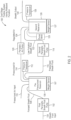
- FIG. 1 is an illustration of a dual-stage fluidics system 100 having reduced pulsation in the sheath output 130.
- the system of FIG. 1 can be used in sorting flow cytometers that require a very stable delivery of sheath fluid to maintain accuracy in sort timing, as well as preventing pulsations in either the measured signal or the frequency of particles arriving at the interrogation area of the sorting flow cytometer.
- Peristaltic pumps are used in various types of instrumentation, especially in the medical field since peristaltic pumps isolate the fluid from any type of outside contamination. Peristaltic pumps are relatively inexpensive and are capable of creating pressures from 0-60 pounds per square inch (PSI), (0-413.69 Kilopascal (kPa)) or higher.
- PSI pounds per square inch
- kPa Kilopascal
- Peristaltic pumps are also very reliable and have relatively long lifetimes. Because of the low cost and the other advantages of using peristaltic pumps, various attempts have been made to create pulsation dampeners for peristaltic pumps. However, these dampeners have failed to eliminate or significantly reduce the inherent pulsatile output of the peristaltic pumps. Peristaltic pumps operate by using rollers that compress tubing and rotate along a length of the tubing to create a pumping action. As such, the pumping action creates waves of pressure in the pumped fluid as rollers lift at the end of the tubing length.
- Dampening can be achieved, to some extent, using a reservoir in which sheath fluid can be pumped to a certain level and air provided to the reservoir at a pre determined pressure using an air pump and an air regulator to maintain a predetermined pressure, which causes the sheath fluid to flow out from the reservoir at that pressure.
- air regulators are expensive and operate by using bleed air to maintain accuracy of the pressure of the regulate air.
- the amount of bleed air is controlled by an orifice. The use of larger orifices allows for greater responsiveness. However, larger orifices result in a larger amount of air utilized.
- peristaltic pumps are much less expensive and have virtually no vibration.
- peristaltic pumps have a pulsatile nature, the use of peristaltic pumps to pump both air and sheath fluid requires a reservoir that is very large to create a sufficient amount of dampening to provide a sheath output flow that is suitable for use in a sorting flow cytometer.
- a reservoir is pressurized to 60 psi (413.69 kPa)
- a reservoir of at least 25 liters would be required to provide sufficient dampening.
- Such a reservoir is, however, entirely too large for a sorting flow cytometer.
- a dual-stage fluidics system 100 which uses two reservoirs, i.e., a pre-pressurized reservoir 106 and a second reservoir 126 and three peristaltic pumps 102, 118 and 120.
- Peristaltic pumps 102, 118, 120 are used to provide a reliable system for pumping both air and sheath fluid to create a stable sheath output 130.
- the pulsatile nature of the peristaltic pumps has very little effect on the stability of the sheath output 130.
- About the same pressure is considered to be approximately 1.0% of the pressure.
- sheath fluid input 104 flows to a first peristaltic sheath fluid pump 102.
- the first peristaltic sheath fluid pump 102 pumps the sheath fluid input 104 and creates a pumped sheath fluid 108.
- the pumped sheath fluid 108 is transferred to a pre-pressurized reservoir 106.
- a weight sensor 107 measures that weight of the pre pressurized reservoir 106 and a computerized control system 151 ( FIG. 4 ) controls the flow of pumped sheath fluid 108 into the pre-pressurized reservoir 106.
- Weight sensor 107 generates a weight signal that is used to control the first peristaltic sheath fluid pump 102 to either pump additional fluid into the pre-pressurized reservoir 106 or remove fluid from the pre-pressurized reservoir 106. Since the first peristaltic sheath fluid pump 102 can operate in either direction, i.e., it can either pump fluid into the pre-pressurized reservoir 106 or remove sheath fluid from the pre-pressurized reservoir 106 with a high degree of precision, the amount or weight of the pre-pressurized fluid in the pre-pressurized reservoir can be maintained with a high degree of precision.
- first peristaltic sheath fluid pump can simply be operated to add sheath fluid carefully and stop pumping when weight sensor 107 indicates that the proper weight of sheath fluid is contained in the pre-pressurized reservoir 106.
- the pre-pressurized reservoir 106 therefore contains a pre-determined amount of sheath fluid which fills the pre-pressurized reservoir 106 to a pre-determined level.
- the remaining volume of the pre-pressurized reservoir 106 is filled with pressurized air from the pressurized air input 110.
- the volume in the pre-pressurized reservoir 106 for the pressurized air remains substantially constant, which allows for easier maintenance of air pressure in pre-pressurized reservoir 106 and provides for a more constant total output pressure given that output pressure of a reservoir is related to the air pressure combined with the height of the fluid.
- weight sensor 107 measures the weight of the pre-pressurized reservoir 106 and provides signals to the first peristaltic sheath fluid pump 102 through a computer control system 150 which causes the first peristaltic sheath fluid pump 102 to either add sheath fluid 108 or remove sheath fluid from the pre-pressurized reservoir 106 to maintain a constant weight of sheath fluid in the pre-pressurized reservoir 106.
- Pressure transducer 112 carefully measures the air pressure in the pre-pressurized reservoir 106, and the pressurized air input 110 is adjusted to maintain pressurized air at a pre determined pressure, such as 60 PSI (413.69 kPa) with a delta of 0.25 PSI (1.72 kPa). Since the volume in the pre-pressurized reservoir 106 remains constant, it is easier to maintain a constant air pressure, as indicated above.
- the pressurized air input 110 is created by the air supply system 150 of FIG. 3 , which is explained in more detail below.
- peristaltic pumps such as peristaltic air pump 120
- the input pressure of the air such as from pressurized air 114
- the output regulated air 124 is substantially different from the pressure of the output regulated air 124. This is a result of the pulsatile nature of the peristaltic pumps and the fact that when a peristaltic pump is pumping from an unpressurized or low pressured source, the tubing expands and contracts causing a change in volume which causes the pressure to vary. This variation in volume of the plastic tubing occurs even when very stiff tubing is utilized.
- the input air such as pressurized air 114
- the pressurized air 114 is 60 PSI (413.69 kPa) with a variance of 0.25 PSI (1.72 kPa)
- the pressure of the regulated air 124 can be maintained at 60 PSI (413.69 kPa), with a variance of much less than 0.25 PSI (1.72 kPa), perhaps as low as 0.001 PSI (6.89 Pa), without substantial changes in pressure caused by the tubing.
- the pressurized air 114 is the pressurized air that exists in the pre pressurized reservoir 106 that is provided by pressurized air input 110. Pressurized air 114 is therefore at the same level as the pressurized air input 110 which, for example, can be 60 PSI (413.69 kPa).
- the pressurized air 114 is the input to the peristaltic air pump 120.
- the output of the peristaltic air pump 120 is the regulated air 124.
- the pressurized air 114 would have the same pressure as the pressure of the regulated air 124, i.e., within about 1.0%. However, this may not be the case.
- the air pressure of the pressurized air 114 can be significantly different than the air pressure of regulated air 124 in various embodiments of the disclosed technology.
- the magnitude of the difference will affect the magnitude of the fluctuations in pressure at the sheath output 130.
- the pressure in the pre pressurized reservoir can be any pressure above ambient pressure and the variations in pressure at the sheath output 130 will be reduced as the pressure in pre-pressurized reservoir 106 increases to the pressure of the regulated air 124.
- an especially suitable pressure for pre-pressurized reservoir 106, to minimize fluctuations in pressure in sheath output 130 is the same pressure as the regulated air 124.
- pulsation can be measured directly by pressure variations in reservoir 126 or output 130, or by observing velocity shifts in the flow of the fluid after the fluid leaves output 130. Pressure measurement is particularly convenient, as transducer 128 is already monitoring the pressure of reservoir 126.
- the peristaltic pump 120 functions to isolate the pressurized air 114 from the regulated air 124.
- the pressure transducer 112 detects the air pressure of the air inside of the pre-pressurized reservoir 106. If the air pressure drops below a pre-determined threshold, the computer control system 151, connected to the pressure transducer 112, will generate a control signal that is sent to the air supply system 150 of FIG. 3 , to supply additional air through the pressurized air input 110, as explained below with regard to FIG. 4 . If the pressure in the pre-pressurized reservoir 106 is too high, pressure is removed by the dump valve 142 ( FIG. 3 ), which is disclosed in more detail with respect to the description of FIG. 3 .
- the pre-pressurized air 114 is ideally substantially the same pressure (i.e., within ⁇ 0.25 PSI (+/- 1.72 kPa) at 60 PSI (413.69 kPa)) or about 0.4% as the air pressure in the pre-pressurized reservoir 106, to create a fairly constant output pressure of sheath output 130.
- a variation of only 0.25 PSI (1.72 kPa) can be maintained with a pressure of 60 PSI (413.69 kPa) in the pre-pressurized reservoir 106. Differences in pressure of less than 1.0% are considered to be about or substantially the same.
- a dump valve can be connected to second reservoir 126 to lower the pressure in second reservoir 126.
- the regulated air 124 is then applied to the second reservoir 126.
- a pressure transducer 128 reads the pressure in the second reservoir 126 and transmits that reading to computer control system 151. If the regulated air 124 is too high, the peristaltic pump 120 is operated in reverse to remove air from the second reservoir 126. In this manner, there is no loss of efficiency, such as when an air regulator is used, which causes a large amount of air to be bled from the system and requires large expensive motors that are capable of supplying a large amount of air.
- the pressurized sheath fluid 116 is pumped from the pre-pressurized reservoir 106 by second peristaltic sheath fluid pump 118.
- the second peristaltic sheath fluid pump 118 pumps the pressurized sheath fluid 116 from the pre-pressurized reservoir 106 to the second reservoir 126 to create a low-pulsation sheath fluid 122.
- Second peristaltic sheath fluid pump 118 can either operate in both a forward and reverse direction, to either add to, or subtract from, sheath fluid in the second reservoir 126, or can operate in just a forward direction to just add sheath fluid to second reservoir 126.
- sheath fluid is added to the second reservoir until weight sensor 127 indicates that a predetermined level has been reached.
- Threshold values can be set very tightly so that the level of sheath fluid in the second reservoir 126 is precisely maintained.
- the pressurized sheath fluid 116 can be pressurized at 60 PSI (413.69 kPa), or any desired level, and has a very low fluctuation in pressure, e.g., 0.25 PSI (1.72 kPa).
- the pressurized sheath fluid 116 is pressurized to a level that is substantially the same as the pressurization of a low-pulsation sheath fluid 122, very little fluctuation occurs between the pressurized sheath fluid 116 and the low-pulsation sheath fluid 122 because there is very little difference between the input pressure of the pressurized sheath fluid 116 and the output pressure of the low-pulsation sheath fluid 122. Again, the lower the difference, the more stable the sheath output 130.
- the second peristaltic sheath fluid pump 128 isolates the input and output so that variations in the pressurized sheath fluid 116 are not transmitted to the low-pulsation sheath fluid 122.
- the low-pulsation sheath fluid 122 is transmitted to the second reservoir 126.
- the second reservoir 126 is filled to a pre-determined amount as indicated by the weight sensor 127.
- a specific volume is maintained in the second reservoir 126 for pressurized air. Since the volume remains substantially constant, i.e., within 1.0%, a substantially constant pressure can be maintained in an easier manner.
- the head pressure of the sheath fluid remains substantially constant so that variations in the overall pressure in second reservoir 126 are not attributable to changes in the head pressure.
- Regulated air 124 is applied to the second reservoir and creates an air pressure that is detected by the pressure transducer 128. If the air pressure in the second reservoir 126 is too high, the pressure transducer, transmits a signal to the computer control system 151 ( FIG. 4 ) which generates a control signal 178 to control peristaltic air pump 120, which can operate in either direction to add additional air or to subtract air from the second reservoir 126. In this manner, the air pressure in the second reservoir 126 can be very closely monitored and maintained to create a sheath output 130 that is very stable and has a very consistent pressure and flow output.
- a dump valve can be used, such as dump valve 129, illustrated in FIG. 2 , to maintain the air pressure in second reservoir 126, and peristaltic air pump 120 is not operated in a reverse direction.
- FIG. 2 discloses a schematic flow diagram of a dual-stage fluidics system 100 that corresponds to the embodiment disclosed in FIG. 1 .
- sheath fluid input 104 provides sheath fluid to a first peristaltic sheath fluid pump 102.
- the pumped sheath fluid 108 is transferred through tubing to a pre-pressurized reservoir 106.
- Weight sensor 107 detects the weight of the pre-pressurized reservoir 106 and generates a weight signal that is used to control the first peristaltic sheath fluid pump 102 to maintain a pre-determined amount of sheath fluid in the pre-pressurized reservoir 106.
- the first peristaltic sheath fluid pump 102 can either add or subtract fluid by operating in a forward or a reverse direction, the amount of sheath fluid in the pre-pressurized reservoir 106 can be maintained with a high degree of accuracy.
- Pressurized air input 110 is provided to the pre-pressurized reservoir 106. Since the pre-pressurized reservoir 106 contains a pre-determined amount of sheath fluid, a constant volume of space is provided in the pre-pressurized reservoir 106 for the pressurized air input 110.
- the pressure transducer 112 detects the air pressure in pre-pressurized reservoir 106 and creates a pressure signal that is used to control the pressurized air input 110.
- the pressurized air in the pre-pressurized reservoir 106 is supplied to peristaltic air pump 120.
- the pressurization of the pressurized air 114 is ideally substantially the same pressurization as the regulated air 124 but can be at any pressurization to reduce variations in pressure of sheath output 130.
- Peristaltic air pump 120 can therefore supply air to the second reservoir 126 by simply adding additional air or subtracting air without changing the air pressure substantially from the input air pressure of the pressurized air 114 to the regulated air 124.
- a dump valve 129 can be used to reduce air pressure in second reservoir 126.
- the regulated air 124 is applied to the second reservoir 126.
- Second reservoir 126 maintains a substantially constant volume for the regulated air 124.
- the pressurized sheath fluid 116 flows from the pre-pressurized reservoir 106 to the second peristaltic sheath pump 118.
- the pressurized sheath fluid 116 has a pressure that is substantially the same as the low-pulsation sheath fluid 122 so that the second peristaltic sheath pump 118 pumps sheath fluid from an input to an output that is substantially the same pressure.
- the pressure of the pressurized sheath fluid can be any pressure, but the closer the pressure of the pressurized sheath fluid to the low-pulsation sheath fluid 122, the lower the variations in the pressure of sheath output 130.
- the low-pulsation sheath fluid 122 has low pressure variations. For example, at pressures of 60 PSI (413.69 kPa), variations of only 0.001 PSI (6.89 Pa) can be achieved in the low-pulsation sheath fluid 122 since the second peristaltic sheath pump 118 is pumping from an input pressure to an output pressure that are substantially the same. In this context, substantially the same means that the input pressure and the output pressure do not vary more than about 1.0% to obtain good results.
- the low-pulsation sheath fluid 122 is transferred to the second reservoir 126.
- Weight sensor 127 measures the weight of the sheath fluid in the second reservoir 126 which is used to generate control signals that control the second peristaltic sheath fluid pump 118, as explained in more detail with respect to the description of FIG. 4 .
- Pressure transducer 128 detects the air pressure within the second reservoir 126 and generates an air pressure signal which is utilized by a computer control system 151 ( FIG. 4 ) that controls a peristaltic air pump 120.
- the air pressure within the second reservoir 126 can therefore be controlled to create variances less than 0.001 PSI (6.89 Pa) at 60 PSI (413.69 kPa) in the second reservoir 126 so that the sheath output 130 is stable and constant.
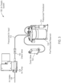
- FIG. 3 is a schematic diagram of an air supply system 150.
- the air supply system 150 is capable of bringing the pressurized air input 110 up to a pressure of 60 PSI (413.69 kPa) or other similar pressure in a short period of time for the volume of air in the pre-pressurized reservoir 132.
- a peristaltic pump to supply the pressurized air input 110 is not a viable alternative since it would take a substantial amount of time to supply the volume of air for the pre-pressurized reservoir 132 using a peristaltic pump.
- Air pump 138 is substantially smaller than air pumps that operate with air regulators that require bleed air to maintain accuracy. As such, air pump 138 is substantially smaller, provides substantially less vibration and can supply a sufficient amount of air to raise the pressurized air input 110 to a desired pressure, such as, for example, 60 PSI (413.69 kPa), in less than a minute or in just a few minutes.
- Air pump 138 create less vibration than air pumps that operate with air regulators. Air pump 138, however, must be sized so that it only operates on an intermittent basis and does not create sufficient vibration that interfere with a sorting process performed by a sorting flow cytometer. Air pump 138 has an air intake 136, at ambient pressure, and pumps the pressurized air through check valve 140. Check valve 140 prevents the pressurized air input 110 from flowing back through the air pump and reducing the pressure of the pressurized air input 110. The pressure transducer 112 reads the pressure in the pre pressurized reservoir 132 and generates an air pressure signal that is used to control the air pump 138, as well as the dump valve 142.
- the air pump 138 When the pressure is low, the air pump 138 is activated to increase the pressure of the pressurized air input 110. If the pressurized transducer 112 detects an air pressure that is greater than a pre-determined threshold pressure, for example, 60.25 PSI (415.41 kPa), then dump valve 142 is activated to carefully reduce the pressure to a pressure that is within the threshold values of the desired pressure, for example, 60 PSI (413.69 kPa) plus 0.25 PSI (1.72 kPa). In this manner, the pre-pressurized reservoir 132 can be maintained at a substantially constant level and can be pressurized in a relatively short time period using an air pump 138 that does not create excessive vibration.
- a pre-determined threshold pressure for example, 60.25 PSI (415.41 kPa)
- dump valve 142 is activated to carefully reduce the pressure to a pressure that is within the threshold values of the desired pressure, for example, 60 PSI (413.69 kPa) plus 0.25 PS
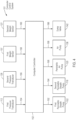
- FIG. 4 is a schematic block diagram of a computer control system 151.
- first pressure transducer 112 generates a first pressure signal 154 which is applied to the computer controller 152.
- Second pressure transducer 128 generates a second pressure signal 156 that is applied to computer controller 152.
- First weight sensor 107 generates a first weight signal 158 that is applied to the computer controller 152.
- a second weight sensor 127 generates a second weight signal 160 that is applied to the computer controller 152.
- the computer controller uses each one of these signals to generate control signals.
- Computer controller 152 generates a control signal 162 to control the first peristaltic sheath pump 102.
- Computer controller 152 generates a control signal 164 to control the second peristaltic sheath pump 118.
- Computer controller 152 generates a control signal 166 that controls the peristaltic air pump 120.
- Computer controller 152 generates a control signal 168 that controls air pump 138.
- Computer controller 152 generates a control signal 186 that is used to control the dump valve 142. In this manner, each of the signals detected by the transducers and sensors is utilized to control the sheath pumps, air pumps and dump valve to create a steady and uniform sheath output flow 130.
- the embodiments of the disclosed technology can provide a sheath fluid output that is very stable and utilizes peristaltic pumps that can operate in either direction for both sheath fluid and air to maintain a highly constant and stable sheath output.
- Two pressurized reservoirs are used which are maintained with a pre-determined amount of sheath fluid which is carefully maintained by two different peristaltic sheath fluid pumps.
- Highly accurate air pressures are maintained in the two pressurized reservoirs which is assisted by the fact that a constant volume of air space is maintained within both of the reservoirs.
- a peristaltic air pump is provided between the two reservoirs which isolates the air pressure of the first reservoir from the second reservoir.
- the peristaltic air pump functions to simply provide or subtract an amount of pressurized air to or from the second reservoir and does not need to substantially adjust the pressure between the two reservoirs.
- a dump valve can be connected to the second reservoir to lower pressure in the second reservoir when the pressure in the second reservoir exceeds a predetermined threshold. In this manner, a constant and very stable output of sheath fluid can be provided.
Landscapes
- Engineering & Computer Science (AREA)
- General Engineering & Computer Science (AREA)
- Mechanical Engineering (AREA)
- Chemical & Material Sciences (AREA)
- Biochemistry (AREA)
- Analytical Chemistry (AREA)
- Life Sciences & Earth Sciences (AREA)
- General Health & Medical Sciences (AREA)
- General Physics & Mathematics (AREA)
- Immunology (AREA)
- Pathology (AREA)
- Health & Medical Sciences (AREA)
- Physics & Mathematics (AREA)
- Dispersion Chemistry (AREA)
- Reciprocating Pumps (AREA)
Description
- The present disclosure relates to the field of fluid handling systems and to the field of reduced-pulsatility fluid flow.
- Various types of instrumentation, including medical research instruments, require a steady flow of fluid at a substantially constant pressure.
US 2013/0333765 A1 describes a sheath delivery system that uses a continuous flow of sheath fluid into a pressurized internal reservoir that substantially matches the outflow of sheath fluid through the nozzle of a flow cytometer. Pumps that pump fluids typically create pulsatile flows of liquid, i.e., the pressure of the flow pulsates as a result of the pulsatile nature of the pump. Highly consistent and constant flow of fluids at a pre determined pressure and rate has been difficult and expensive to achieve. Accordingly, there is a long-felt need in the art for systems and methods that deliver reduced-pulsatility fluid flow. - In meeting the long-felt needs described above, the present disclosure provides, in one aspect, a method of generating a sheath flow for a flow cytometer, comprising: pumping sheath fluid into a first pressurized reservoir using a first peristaltic sheath fluid pump; sensing an amount of the sheath fluid in the first pressurized reservoir to create a first sheath fluid quantity signal; maintaining a predetermined amount of the sheath fluid in the first pressurized reservoir by pumping the sheath fluid into the first pressurized reservoir using the first peristaltic sheath fluid pump in response to the first sheath fluid quantity signal; pumping the sheath fluid from the first pressurized reservoir to a second pressurized reservoir using a second peristaltic sheath fluid pump; sensing an amount of the sheath fluid in the second pressurized reservoir to create a second sheath fluid quantity signal; maintaining a predetermined amount of the sheath fluid in the second pressurized reservoir by pumping the sheath fluid into the second pressurized reservoir using the second peristaltic pump in response to the second sheath fluid quantity signal; supplying air to the first pressurized reservoir using an air pump to pressurize the first pressurized reservoir; pumping air from the first pressurized reservoir to the second pressurized reservoir using a peristaltic air pump to pressurize air to a predetermined air pressure in the second reservoir; maintaining the predetermined air pressure in the second reservoir by pumping air into the second reservoir using the peristaltic air pump.
- The present disclosure further provides, in one aspect, a system that generates a flow of sheath fluid for a flow cytometer, comprising: a first peristaltic sheath fluid pump that pumps the sheath fluid; a first pressurized reservoir that receives the sheath fluid from the first peristaltic pump; a first fluid sensor that senses an amount of the sheath fluid in the first pressurized reservoir and generates a first sheath fluid quantity signal that is used to control the first peristaltic sheath fluid pump to maintain a predetermined amount of sheath fluid in the first pressurized reservoir; a second peristaltic sheath fluid pump that pumps the sheath fluid; a second pressurized reservoir that receives the sheath fluid from the second peristaltic pump; a second fluid sensor that senses an amount of the sheath fluid in the second pressurized reservoir this is used to control the second peristaltic sheath fluid pump to maintain a predetermined amount of sheath fluid in the second pressurized reservoir; a peristaltic air pump that pumps air between the first pressurized reservoir and the second pressurized reservoir.
- In one aspect, the present disclosure provides methods of generating a low-pulsatility fluid flow, comprising: pumping a fluid into a first pressurized reservoir using a first peristaltic fluid pump; sensing an amount of the fluid in the first pressurized reservoir to create a first fluid quantity signal; in response to the first fluid quantity signal, maintaining a predetermined amount of the fluid in the first pressurized reservoir by pumping the fluid into the first pressurized reservoir and/or removing the fluid from the first pressurized reservoir using the first peristaltic fluid pump; pumping the fluid from the first pressurized reservoir to a second pressurized reservoir using a second peristaltic fluid pump; sensing an amount of the fluid in the second pressurized reservoir to create a second fluid quantity signal; in response to the second fluid quantity signal, maintaining a predetermined amount of the fluid in the second pressurized reservoir by pumping the sheath fluid into the second pressurized reservoir using the second peristaltic pump and/or removing the fluid from the second pressurized reservoir in response to the second sheath fluid quantity signal; supplying air to the first pressurized reservoir so as to pressurize the first pressurized reservoir; communicating air from the first pressurized reservoir to the second pressurized reservoir using a peristaltic air pump to pressurize air in the second reservoir to a predetermined air pressure; and maintaining the predetermined air pressure in the second reservoir by communicating air into the second pressurized reservoir using the peristaltic air pump.
- Also provided are systems for generating a low-pulsatility fluid flow, comprising: a first peristaltic fluid pump; a first pressurized reservoir configured to receive a fluid from the first peristaltic pump; a first fluid sensor that generates a first fluid quantity signal in response to an amount of the fluid in the first pressurized reservoir and, the system being configured to modulate the operation of the first peristaltic fluid pump at least partially in response to the first fluid quantity signal so as to maintain a predetermined amount of fluid in the first pressurized reservoir; a second peristaltic fluid pump configured to pump the fluid from the first pressurized reservoir; a second pressurized reservoir that receives the fluid from the second peristaltic pump; a second fluid sensor that generates a second fluid quantity signal in response to an amount of the fluid in the second pressurized reservoir, the system being configured to modulate the operation of the second peristaltic fluid pump at least partially in response to the second fluid quantity signal so as to maintain a predetermined amount of fluid in the second pressurized reservoir; and a peristaltic air pump configured to pump air between the first pressurized reservoir and the second pressurized reservoir.
- Additionally disclosed are methods, comprising operating a system according to the present disclosure, e.g., according to any one of Aspects 24-42.
- Further provided are methods, comprising performing flow cytometry with a fluid delivered from a system according to the present disclosure, e.g., any one of Aspects 24-42.
- Also disclosed are methods, comprising: with a fluidic circuit comprising (i) a first pressurized reservoir having at least some of a liquid disposed therein, (ii) a second pressurized reservoir having at least some of the liquid disposed therein, (iii) a pump configured to communicate air between the first pressurized reservoir and the second pressurized reservoir, and (iv) a pump configured to communicate the fluid between the first pressurized reservoir and the second pressurized reservoir, modulating the air communicated to and/or withdrawn from the first pressurized reservoir and the second pressurized reservoir and modulating the fluid communicated to and/or withdrawn from the first pressurized reservoir and the second pressurized reservoir; the modulating being performed so as to maintain the second pressurized reservoir at a pressure of within about 1% of a pressure of the first pressurized reservoir.
- In the drawings, which are not necessarily drawn to scale, like numerals may describe similar components in different views. Like numerals having different letter suffixes can represent different instances of similar components. The drawings illustrate generally, by way of example, but not by way of limitation, various aspects discussed in the present document. In the drawings:
-
FIG. 1 is a schematic illustration of an embodiment of dual-stage fluidics system having reduced pulsation. -
FIG. 2 is a schematic flow diagram that illustrates the operation of the dual-stage fluidics system of the embodiment ofFIG. 1 . -
FIG. 3 is a schematic diagram of an embodiment of an air supply system for supplying pressurized air to a pre-pressurized reservoir. -
FIG. 4 is a schematic block diagram of a control system that can be utilized with the disclosed embodiments. - The present disclosure may be understood more readily by reference to the following detailed description of desired embodiments and the examples included therein.
- Unless otherwise defined, all technical and scientific terms used herein have the same meaning as commonly understood by one of ordinary skill in the art. In case of conflict, the present document, including definitions, will control. Preferred methods and materials are described below, although methods and materials similar or equivalent to those described herein can be used in practice or testing.
- The materials, methods, and examples disclosed herein are illustrative only and not intended to be limiting.
- The singular forms "a," "an," and "the" include plural referents unless the context clearly dictates otherwise.
- As used in the specification and in the claims, the term "comprising" can include the embodiments "consisting of" and "consisting essentially of." The terms "comprise(s)," "include(s)," "having," "has," "can," "contain(s)," and variants thereof, as used herein, are intended to be open-ended transitional phrases, terms, or words that require the presence of the named ingredients/steps and permit the presence of other ingredients/steps. However, such description should be construed as also describing compositions or processes as "consisting of" and "consisting essentially of" the enumerated ingredients/steps, which allows the presence of only the named ingredients/steps, along with any impurities that might result therefrom, and excludes other ingredients/steps.
- As used herein, the terms "about" and "at or about" mean that the amount or value in question can be the value designated some other value approximately or about the same. It is generally understood, as used herein, that it is the nominal value indicated ±10% variation unless otherwise indicated or inferred. The term is intended to convey that similar values promote equivalent results or effects recited in the claims. That is, it is understood that amounts, sizes, formulations, parameters, and other quantities and characteristics are not and need not be exact, but can be approximate and/or larger or smaller, as desired, reflecting tolerances, conversion factors, rounding off, measurement error and the like, and other factors known to those of skill in the art. In general, an amount, size, formulation, parameter or other quantity or characteristic is "about" or "approximate" whether or not expressly stated to be such. It is understood that where "about" is used before a quantitative value, the parameter also includes the specific quantitative value itself, unless specifically stated otherwise.
- Unless indicated to the contrary, the numerical values should be understood to include numerical values which are the same when reduced to the same number of significant figures and numerical values which differ from the stated value by less than the experimental error of conventional measurement technique of the type described in the present application to determine the value.
- All ranges disclosed herein are inclusive of the recited endpoint and independently of the endpoints (e.g., "between 2 grams and 10 grams, and all the intermediate values includes 2 grams, 10 grams, and all intermediate values"). The endpoints of the ranges and any values disclosed herein are not limited to the precise range or value; they are sufficiently imprecise to include values approximating these ranges and/or values. All ranges are combinable.
- As used herein, approximating language can be applied to modify any quantitative representation that can vary without resulting in a change in the basic function to which it is related. Accordingly, a value modified by a term or terms, such as "about" and "substantially," may not be limited to the precise value specified, in some cases. In at least some instances, the approximating language can correspond to the precision of an instrument for measuring the value. The modifier "about" should also be considered as disclosing the range defined by the absolute values of the two endpoints. For example, the expression "from about 2 to about 4" also discloses the range "from 2 to 4." The term "about" can refer to plus or minus 10% of the indicated number. For example, "about 10%" can indicate a range of 9% to 11%, and "about 1" can mean from 0.9-1.1. Other meanings of "about" can be apparent from the context, such as rounding off, so, for example "about 1" can also mean from 0.5 to 1.4. Further, the term "comprising" should be understood as having its open- ended meaning of "including," but the term also includes the closed meaning of the term "consisting." For example, a composition that comprises components A and B can be a composition that includes A, B, and other components, but can also be a composition made of A and B only.
- The following Aspects are illustrative only and do not serve to limit the scope of the present disclosure or the appended claims.
- The present disclosure relates to a method of generating a low-pulsatility fluid flow, comprising: pumping a fluid into a first pressurized reservoir using a first peristaltic fluid pump; sensing an amount of the fluid in the first pressurized reservoir to create a first fluid quantity signal; in response to the first fluid quantity signal, maintaining a predetermined amount of the fluid in the first pressurized reservoir by pumping the fluid into the first pressurized reservoir and/or removing the fluid from the first pressurized reservoir using the first peristaltic fluid pump; pumping the fluid from the first pressurized reservoir to a second pressurized reservoir using a second peristaltic fluid pump; sensing an amount of the fluid in the second pressurized reservoir to create a second fluid quantity signal; in response to the second fluid quantity signal, maintaining a predetermined amount of the fluid in the second pressurized reservoir by pumping the sheath fluid into the second pressurized reservoir using the second peristaltic pump and/or removing the fluid from the second pressurized reservoir in response to the second sheath fluid quantity signal; supplying air to the first pressurized reservoir so as to pressurize the first pressurized reservoir; communicating air from the first pressurized reservoir to the second pressurized reservoir using a peristaltic air pump to pressurize air in the second reservoir to a predetermined air pressure; and maintaining the predetermined air pressure in the second reservoir by communicating air into the second pressurized reservoir using the peristaltic air pump.
- Maintaining the predetermined air pressure in the second pressurized reservoir can further comprise maintaining the predetermined pressure in the second pressurized reservoir by removing air from the second pressurized reservoir using the peristaltic air pump.
- Supplying air to the first pressurized reservoir can comprise supplying air to the first pressurized reservoir at an air pressure that is substantially the same as the predetermined pressure.
- Sensing an amount of the fluid in the first pressurized reservoir can comprise weighing the first pressurized reservoir using a first weight sensor to give rise to the first fluid quantity signal.
- Maintaining a predetermined amount of the fluid in the first pressurized reservoir can comprise, in response to the first fluid quantity signal, pumping the fluid into the first pressurized reservoir and removing the fluid from the first pressurized reservoir with the peristaltic fluid pump.
- Sensing an amount of the fluid in the second pressurized reservoir can comprise weighing the second pressurized reservoir using a second weight sensor to give rise to the second fluid quantity signal.
- Maintaining the predetermined amount of the fluid in the second pressurized reservoir can comprise, in response to the second fluid quantity signal, pumping the fluid into the second pressurized reservoir and removing fluid from the second pressurized reservoir using the second peristaltic fluid pump.
- The method can further comprise detecting an air pressure in the first pressurized reservoir using a first pressure transducer and generating a first air pressure transducer signal from the first pressure transducer.
- The method can further comprise modulating operation of the peristaltic air pump at least partially in response to the first air pressure transducer signal.
- The method can further comprise modulating operation of a release valve in fluid communication with the first reservoir at least partially in response to the first air pressure transducer signal.
- The method can further comprise detecting an air pressure in the second pressurized reservoir using a second pressure transducer and generating a second air pressure transducer signal from the second pressure transducer.
- The method can further comprise modulating operation of the peristaltic air pump at least partially in response to the second air pressure transducer signal.
- Maintaining the predetermined air pressure in the second pressurized reservoir can comprise opening a release valve in fluid communication with the second reservoir at least partially in response to the second air pressure transducer signal.
- The method can further comprise modulating operation of a third fluid pump at least partially in response to the second fluid quantity signal, the third fluid pump configured to remove fluid from the second pressurized reservoir.
- The method can further comprise modulating operation of the first peristaltic fluid pump at least partially in response to the second fluid quantity signal.
- The method can further comprise modulating operation of the second peristaltic fluid pump at least partially in response to the first fluid quantity signal.
- The method can further comprise modulating operation of a valve so as to deliver input air to the first pressurized reservoir.
- The input air can be pressurized by a boost pump.
- Air exiting the first pressurized reservoir can be at a pressure of within about 1 % of the pressure of air entering the second pressurized reservoir.
- Air exiting the first pressurized reservoir can be at a pressure of within about 0.5% of the pressure of air entering the second pressurized reservoir.
- Fluid exiting the first pressurized reservoir can be at a pressure of within about 5% of the pressure of fluid entering the second pressurized reservoir.
- Fluid exiting the first pressurized reservoir can be at a pressure of within about 1% of the pressure of fluid entering the second pressurized reservoir.
- The fluid can be a sheath fluid and the method can further comprise communicating the sheath fluid from the second pressurized reservoir to a flow cytometer.
- The present disclosure also relates to a system for generating a low-pulsatility fluid flow, comprising: a first peristaltic fluid pump; a first pressurized reservoir configured to receive a fluid from the first peristaltic pump; a first fluid sensor that generates a first fluid quantity signal in response to an amount of the fluid in the first pressurized reservoir and, the system being configured to modulate the operation of the first peristaltic fluid pump at least partially in response to the first fluid quantity signal so as to maintain a predetermined amount of fluid in the first pressurized reservoir; a second peristaltic fluid pump configured to pump the fluid from the first pressurized reservoir; a second pressurized reservoir that receives the fluid from the second peristaltic pump; a second fluid sensor that generates a second fluid quantity signal in response to an amount of the fluid in the second pressurized reservoir, the system being configured to modulate the operation of the second peristaltic fluid pump at least partially in response to the second fluid quantity signal so as to maintain a predetermined amount of fluid in the second pressurized reservoir; and a peristaltic air pump configured to pump air between the first pressurized reservoir and the second pressurized reservoir.
- The system can be configured such that the peristaltic air pump operates to maintain the first pressurized reservoir and the second pressurized reservoir at substantially the same pressure.
- The first fluid sensor can be configured to weigh the first pressurized reservoir.
- The first fluid sensor can be configured to determine a level of fluid in the first pressurized reservoir.
- The second fluid sensor can be configured to weigh the second pressurized reservoir.
- The second fluid sensor can be configured to determine a level of fluid in the second pressurized reservoir.
- The system can further comprise a first pressure transducer that generates a first air pressure signal in response to a pressure within the first pressurized reservoir.
- The system can further comprise a second pressure transducer that generates a second air pressure signal in response to a pressure within the second pressurized reservoir.
- The system can further comprise a first valve in fluid communication with the first pressurized reservoir.
- The valve can reduce air pressure in the first pressurized reservoir if the air pressure in the first pressurized reservoir exceeds a threshold pressure.
- The system can further comprise a second valve in fluid communication with the second pressurized reservoir.
- The valve can reduce air pressure in the second pressurized reservoir if the air pressure in the second pressurized reservoir exceeds a threshold pressure.
- The system can further comprise a boost pump configured to deliver air to the first pressurized reservoir.
- The boost pump can be operable to maintain a predetermined pressure in the first pressurized reservoir.
- The system can further comprise: a control signal generator, wherein the control signal generator can be configured to generate a first peristaltic pump control signal in response to the first fluid quantity signal, which first peristaltic pump signal can be used to modulate operation of the first peristaltic fluid pump to achieve a first predetermined amount of fluid in the first pressurized reservoir by pumping the fluid in a forward direction into the first pressurized reservoir and/or in a reverse direction out of the first pressurized reservoir, the control signal generator can be configured to generate a second peristaltic pump control signal in response to the second fluid quantity signal, which second peristaltic pump signal can be used to modulate operation of the second peristaltic fluid pump to achieve a second predetermined amount of fluid in the second pressurized reservoir by pumping the fluid in a forward direction into the second pressurized reservoir and/or in a reverse direction out of the second pressurized reservoir, the control signal generator can generate a peristaltic air pump control signal in response to a signal related to a pressure in at least one of the first pressurized reservoir and the second pressurized reservoir, which peristaltic air pump control signal can be used to modulate operation of the peristaltic air pump to achieve a predetermined pressure in the second reservoir.
- The system can be configured such that fluid entering the second peristaltic fluid pump can define a pressure Pentry, fluid exiting the second peristaltic pump can define a pressure Pexit, and Pexit can be within about 1% of the value of Penny.
- Pexit can be within about 0.5% of the value of Pentry.
- The system can further comprise a flow cytometer, the flow cytometer being in fluid communication with the second pressurized reservoir.
- The system can be configured so as to maintain the second pressurized reservoir at a pressure of within about 1% of a pressure of the first pressurized reservoir.
- The present disclosure also relates to a method, comprising operating a system as discussed above.
- The present disclosure also relates to a method, comprising performing flow cytometry with a fluid delivered from a system as discussed above.
- The present disclosure also relates to a method, which can comprise: with a fluidic circuit comprising (i) a first pressurized reservoir having at least some of a liquid disposed therein, (ii) a second pressurized reservoir having at least some of the liquid disposed therein, (iii) a pump configured to communicate air between the first pressurized reservoir and the second pressurized reservoir, and (iv) a pump configured to communicate the fluid between the first pressurized reservoir and the second pressurized reservoir, modulating the air communicated to and/or withdrawn from the first pressurized reservoir and the second pressurized reservoir and modulating the fluid communicated to and/or withdrawn from the first pressurized reservoir and the second pressurized reservoir; the modulating being performed so as to maintain the second pressurized reservoir at a pressure of within about 1% of a pressure of the first pressurized reservoir.
- Said method can further comprise communicating at least some of the fluid from the second reservoir to a flow cytometer.
- The following descriptions of the non-limiting figures are exemplary only and do not limit the scope of the present disclosure or the appended claims.
-
FIG. 1 is an illustration of a dual-stage fluidics system 100 having reduced pulsation in thesheath output 130. The system ofFIG. 1 can be used in sorting flow cytometers that require a very stable delivery of sheath fluid to maintain accuracy in sort timing, as well as preventing pulsations in either the measured signal or the frequency of particles arriving at the interrogation area of the sorting flow cytometer. Peristaltic pumps are used in various types of instrumentation, especially in the medical field since peristaltic pumps isolate the fluid from any type of outside contamination. Peristaltic pumps are relatively inexpensive and are capable of creating pressures from 0-60 pounds per square inch (PSI), (0-413.69 Kilopascal (kPa)) or higher. Peristaltic pumps are also very reliable and have relatively long lifetimes. Because of the low cost and the other advantages of using peristaltic pumps, various attempts have been made to create pulsation dampeners for peristaltic pumps. However, these dampeners have failed to eliminate or significantly reduce the inherent pulsatile output of the peristaltic pumps. Peristaltic pumps operate by using rollers that compress tubing and rotate along a length of the tubing to create a pumping action. As such, the pumping action creates waves of pressure in the pumped fluid as rollers lift at the end of the tubing length. - Dampening can be achieved, to some extent, using a reservoir in which sheath fluid can be pumped to a certain level and air provided to the reservoir at a pre determined pressure using an air pump and an air regulator to maintain a predetermined pressure, which causes the sheath fluid to flow out from the reservoir at that pressure. Although such a system can provide a fairly stable flow of sheath fluid, air regulators are expensive and operate by using bleed air to maintain accuracy of the pressure of the regulate air. The amount of bleed air is controlled by an orifice. The use of larger orifices allows for greater responsiveness. However, larger orifices result in a larger amount of air utilized. As a result, to obtain a supply of highly regulated air, larger, more complex and expensive pumps would be required, and the vibrations created by the pumps would also have to be managed to not interfere with vibrations that can alter the sorting process when used in sorting flow cytometers.
- On the other hand, peristaltic pumps are much less expensive and have virtually no vibration. Using a peristaltic pump for pumping air instead of an expensive air pump that vibrates, solves the problem of the vibration and allows the air pressure in the reservoir to be carefully maintained since the peristaltic pump can be operated in both the forward and reverse direction so that air can be added or subtracted in a precise manner in a reservoir without bleeding air through an air regulator. However, because peristaltic pumps have a pulsatile nature, the use of peristaltic pumps to pump both air and sheath fluid requires a reservoir that is very large to create a sufficient amount of dampening to provide a sheath output flow that is suitable for use in a sorting flow cytometer. For example, if a reservoir is pressurized to 60 psi (413.69 kPa), a reservoir of at least 25 liters would be required to provide sufficient dampening. Such a reservoir is, however, entirely too large for a sorting flow cytometer.
- Referring again to
FIG. 1 , a dual-stage fluidics system 100 is illustrated which uses two reservoirs, i.e., apre-pressurized reservoir 106 and asecond reservoir 126 and threeperistaltic pumps Peristaltic pumps stable sheath output 130. By using two reservoirs, that are both pressurized, and in the best case, are pressurized to about the same pressure, the pulsatile nature of the peristaltic pumps has very little effect on the stability of thesheath output 130. About the same pressure is considered to be approximately 1.0% of the pressure. - As illustrated in
FIG. 1 ,sheath fluid input 104 flows to a first peristalticsheath fluid pump 102. The first peristalticsheath fluid pump 102 pumps thesheath fluid input 104 and creates a pumpedsheath fluid 108. The pumpedsheath fluid 108 is transferred to apre-pressurized reservoir 106. Aweight sensor 107 measures that weight of the prepressurized reservoir 106 and a computerized control system 151 (FIG. 4 ) controls the flow of pumpedsheath fluid 108 into thepre-pressurized reservoir 106.Weight sensor 107 generates a weight signal that is used to control the first peristalticsheath fluid pump 102 to either pump additional fluid into thepre-pressurized reservoir 106 or remove fluid from thepre-pressurized reservoir 106. Since the first peristalticsheath fluid pump 102 can operate in either direction, i.e., it can either pump fluid into thepre-pressurized reservoir 106 or remove sheath fluid from thepre-pressurized reservoir 106 with a high degree of precision, the amount or weight of the pre-pressurized fluid in the pre-pressurized reservoir can be maintained with a high degree of precision. Alternatively, first peristaltic sheath fluid pump can simply be operated to add sheath fluid carefully and stop pumping whenweight sensor 107 indicates that the proper weight of sheath fluid is contained in thepre-pressurized reservoir 106. Thepre-pressurized reservoir 106 therefore contains a pre-determined amount of sheath fluid which fills thepre-pressurized reservoir 106 to a pre-determined level. The remaining volume of thepre-pressurized reservoir 106 is filled with pressurized air from thepressurized air input 110. By maintaining a substantially constant level of sheath fluid in thepre-pressurized reservoir 106, the volume in thepre-pressurized reservoir 106 for the pressurized air remains substantially constant, which allows for easier maintenance of air pressure inpre-pressurized reservoir 106 and provides for a more constant total output pressure given that output pressure of a reservoir is related to the air pressure combined with the height of the fluid. - As illustrated in
FIG. 1 ,weight sensor 107 measures the weight of thepre-pressurized reservoir 106 and provides signals to the first peristalticsheath fluid pump 102 through acomputer control system 150 which causes the first peristalticsheath fluid pump 102 to either addsheath fluid 108 or remove sheath fluid from thepre-pressurized reservoir 106 to maintain a constant weight of sheath fluid in thepre-pressurized reservoir 106.Pressure transducer 112 carefully measures the air pressure in thepre-pressurized reservoir 106, and thepressurized air input 110 is adjusted to maintain pressurized air at a pre determined pressure, such as 60 PSI (413.69 kPa) with a delta of 0.25 PSI (1.72 kPa). Since the volume in thepre-pressurized reservoir 106 remains constant, it is easier to maintain a constant air pressure, as indicated above. Thepressurized air input 110 is created by theair supply system 150 ofFIG. 3 , which is explained in more detail below. - It has also been discovered that variations in air pressure are created by peristaltic pumps, such as
peristaltic air pump 120, when the input pressure of the air, such as frompressurized air 114, is substantially different from the pressure of the output regulatedair 124. This is a result of the pulsatile nature of the peristaltic pumps and the fact that when a peristaltic pump is pumping from an unpressurized or low pressured source, the tubing expands and contracts causing a change in volume which causes the pressure to vary. This variation in volume of the plastic tubing occurs even when very stiff tubing is utilized. However, it has been discovered that when the input air, such aspressurized air 114, is at substantially the same pressure as theregulated air 124, i.e., within 1.0%, expansion and contraction of the tubing is minimal. For example, if thepressurized air 114 is 60 PSI (413.69 kPa) with a variance of 0.25 PSI (1.72 kPa), it has been found that the pressure of theregulated air 124 can be maintained at 60 PSI (413.69 kPa), with a variance of much less than 0.25 PSI (1.72 kPa), perhaps as low as 0.001 PSI (6.89 Pa), without substantial changes in pressure caused by the tubing. - The
pressurized air 114 is the pressurized air that exists in the prepressurized reservoir 106 that is provided bypressurized air input 110.Pressurized air 114 is therefore at the same level as thepressurized air input 110 which, for example, can be 60 PSI (413.69 kPa). Thepressurized air 114 is the input to theperistaltic air pump 120. The output of theperistaltic air pump 120 is theregulated air 124. In an ideal embodiment, thepressurized air 114 would have the same pressure as the pressure of theregulated air 124, i.e., within about 1.0%. However, this may not be the case. The air pressure of thepressurized air 114 can be significantly different than the air pressure ofregulated air 124 in various embodiments of the disclosed technology. The magnitude of the difference will affect the magnitude of the fluctuations in pressure at thesheath output 130. Accordingly, the pressure in the pre pressurized reservoir can be any pressure above ambient pressure and the variations in pressure at thesheath output 130 will be reduced as the pressure inpre-pressurized reservoir 106 increases to the pressure of theregulated air 124. Again, however, an especially suitable pressure forpre-pressurized reservoir 106, to minimize fluctuations in pressure insheath output 130, is the same pressure as theregulated air 124. Without being bound to any particular theory or embodiment, pulsation can be measured directly by pressure variations inreservoir 126 oroutput 130, or by observing velocity shifts in the flow of the fluid after the fluid leavesoutput 130. Pressure measurement is particularly convenient, astransducer 128 is already monitoring the pressure ofreservoir 126. - Referring again to
FIG. 1 , theperistaltic pump 120 functions to isolate thepressurized air 114 from theregulated air 124. Thepressure transducer 112 detects the air pressure of the air inside of thepre-pressurized reservoir 106. If the air pressure drops below a pre-determined threshold, thecomputer control system 151, connected to thepressure transducer 112, will generate a control signal that is sent to theair supply system 150 ofFIG. 3 , to supply additional air through thepressurized air input 110, as explained below with regard toFIG. 4 . If the pressure in thepre-pressurized reservoir 106 is too high, pressure is removed by the dump valve 142 (FIG. 3 ), which is disclosed in more detail with respect to the description ofFIG. 3 . As such, thepre-pressurized air 114 is ideally substantially the same pressure (i.e., within ± 0.25 PSI (+/- 1.72 kPa) at 60 PSI (413.69 kPa)) or about 0.4% as the air pressure in thepre-pressurized reservoir 106, to create a fairly constant output pressure ofsheath output 130. Using the systems disclosed herein, testing has shown that a variation of only 0.25 PSI (1.72 kPa) can be maintained with a pressure of 60 PSI (413.69 kPa) in thepre-pressurized reservoir 106. Differences in pressure of less than 1.0% are considered to be about or substantially the same. Alternatively, a dump valve can be connected tosecond reservoir 126 to lower the pressure insecond reservoir 126. - As also illustrated in
FIG. 1 , theregulated air 124 is then applied to thesecond reservoir 126. Apressure transducer 128 reads the pressure in thesecond reservoir 126 and transmits that reading tocomputer control system 151. If theregulated air 124 is too high, theperistaltic pump 120 is operated in reverse to remove air from thesecond reservoir 126. In this manner, there is no loss of efficiency, such as when an air regulator is used, which causes a large amount of air to be bled from the system and requires large expensive motors that are capable of supplying a large amount of air. - The
pressurized sheath fluid 116, illustrated inFIG. 1 , is pumped from thepre-pressurized reservoir 106 by second peristalticsheath fluid pump 118. The second peristalticsheath fluid pump 118 pumps thepressurized sheath fluid 116 from thepre-pressurized reservoir 106 to thesecond reservoir 126 to create a low-pulsation sheath fluid 122. Second peristalticsheath fluid pump 118 can either operate in both a forward and reverse direction, to either add to, or subtract from, sheath fluid in thesecond reservoir 126, or can operate in just a forward direction to just add sheath fluid tosecond reservoir 126. In the latter case, sheath fluid is added to the second reservoir untilweight sensor 127 indicates that a predetermined level has been reached. Threshold values can be set very tightly so that the level of sheath fluid in thesecond reservoir 126 is precisely maintained. Thepressurized sheath fluid 116 can be pressurized at 60 PSI (413.69 kPa), or any desired level, and has a very low fluctuation in pressure, e.g., 0.25 PSI (1.72 kPa). Since thepressurized sheath fluid 116 is pressurized to a level that is substantially the same as the pressurization of a low-pulsation sheath fluid 122, very little fluctuation occurs between thepressurized sheath fluid 116 and the low-pulsation sheath fluid 122 because there is very little difference between the input pressure of thepressurized sheath fluid 116 and the output pressure of the low-pulsation sheath fluid 122. Again, the lower the difference, the more stable thesheath output 130. In addition, the second peristalticsheath fluid pump 128 isolates the input and output so that variations in thepressurized sheath fluid 116 are not transmitted to the low-pulsation sheath fluid 122. - As also illustrated in
FIG. 1 , the low-pulsation sheath fluid 122 is transmitted to thesecond reservoir 126. Thesecond reservoir 126 is filled to a pre-determined amount as indicated by theweight sensor 127. By filling thesecond reservoir 126 with sheath fluid to a pre-determined amount or pre-determined level, a specific volume is maintained in thesecond reservoir 126 for pressurized air. Since the volume remains substantially constant, i.e., within 1.0%, a substantially constant pressure can be maintained in an easier manner. In that regard, the head pressure of the sheath fluid remains substantially constant so that variations in the overall pressure insecond reservoir 126 are not attributable to changes in the head pressure.Regulated air 124 is applied to the second reservoir and creates an air pressure that is detected by thepressure transducer 128. If the air pressure in thesecond reservoir 126 is too high, the pressure transducer, transmits a signal to the computer control system 151 (FIG. 4 ) which generates a control signal 178 to controlperistaltic air pump 120, which can operate in either direction to add additional air or to subtract air from thesecond reservoir 126. In this manner, the air pressure in thesecond reservoir 126 can be very closely monitored and maintained to create asheath output 130 that is very stable and has a very consistent pressure and flow output. Alternatively, a dump valve can be used, such asdump valve 129, illustrated inFIG. 2 , to maintain the air pressure insecond reservoir 126, andperistaltic air pump 120 is not operated in a reverse direction. -
FIG. 2 discloses a schematic flow diagram of a dual-stage fluidics system 100 that corresponds to the embodiment disclosed inFIG. 1 . As illustrated inFIG. 2 ,sheath fluid input 104 provides sheath fluid to a first peristalticsheath fluid pump 102. The pumpedsheath fluid 108 is transferred through tubing to apre-pressurized reservoir 106.Weight sensor 107 detects the weight of thepre-pressurized reservoir 106 and generates a weight signal that is used to control the first peristalticsheath fluid pump 102 to maintain a pre-determined amount of sheath fluid in thepre-pressurized reservoir 106. Since the first peristalticsheath fluid pump 102 can either add or subtract fluid by operating in a forward or a reverse direction, the amount of sheath fluid in thepre-pressurized reservoir 106 can be maintained with a high degree of accuracy.Pressurized air input 110 is provided to thepre-pressurized reservoir 106. Since thepre-pressurized reservoir 106 contains a pre-determined amount of sheath fluid, a constant volume of space is provided in thepre-pressurized reservoir 106 for thepressurized air input 110. Thepressure transducer 112 detects the air pressure inpre-pressurized reservoir 106 and creates a pressure signal that is used to control thepressurized air input 110. The pressurized air in thepre-pressurized reservoir 106 is supplied toperistaltic air pump 120. The pressurization of thepressurized air 114 is ideally substantially the same pressurization as theregulated air 124 but can be at any pressurization to reduce variations in pressure ofsheath output 130.Peristaltic air pump 120 can therefore supply air to thesecond reservoir 126 by simply adding additional air or subtracting air without changing the air pressure substantially from the input air pressure of thepressurized air 114 to theregulated air 124. Alternatively, adump valve 129 can be used to reduce air pressure insecond reservoir 126. Theregulated air 124 is applied to thesecond reservoir 126.Second reservoir 126 maintains a substantially constant volume for theregulated air 124. - As also illustrated in
FIG. 2 , thepressurized sheath fluid 116 flows from thepre-pressurized reservoir 106 to the secondperistaltic sheath pump 118. Thepressurized sheath fluid 116 has a pressure that is substantially the same as the low-pulsation sheath fluid 122 so that the secondperistaltic sheath pump 118 pumps sheath fluid from an input to an output that is substantially the same pressure. Again, the pressure of the pressurized sheath fluid can be any pressure, but the closer the pressure of the pressurized sheath fluid to the low-pulsation sheath fluid 122, the lower the variations in the pressure ofsheath output 130. When the pressures are about the same, the low-pulsation sheath fluid 122 has low pressure variations. For example, at pressures of 60 PSI (413.69 kPa), variations of only 0.001 PSI (6.89 Pa) can be achieved in the low-pulsation sheath fluid 122 since the secondperistaltic sheath pump 118 is pumping from an input pressure to an output pressure that are substantially the same. In this context, substantially the same means that the input pressure and the output pressure do not vary more than about 1.0% to obtain good results. The low-pulsation sheath fluid 122 is transferred to thesecond reservoir 126.Weight sensor 127 measures the weight of the sheath fluid in thesecond reservoir 126 which is used to generate control signals that control the second peristalticsheath fluid pump 118, as explained in more detail with respect to the description ofFIG. 4 .Pressure transducer 128 detects the air pressure within thesecond reservoir 126 and generates an air pressure signal which is utilized by a computer control system 151 (FIG. 4 ) that controls aperistaltic air pump 120. The air pressure within thesecond reservoir 126 can therefore be controlled to create variances less than 0.001 PSI (6.89 Pa) at 60 PSI (413.69 kPa) in thesecond reservoir 126 so that thesheath output 130 is stable and constant. -
FIG. 3 is a schematic diagram of anair supply system 150. Theair supply system 150 is capable of bringing thepressurized air input 110 up to a pressure of 60 PSI (413.69 kPa) or other similar pressure in a short period of time for the volume of air in thepre-pressurized reservoir 132. Using a peristaltic pump to supply thepressurized air input 110 is not a viable alternative since it would take a substantial amount of time to supply the volume of air for thepre-pressurized reservoir 132 using a peristaltic pump. For example, typical implementations would require on the order of an hour or two of pumping before the pressure could be raised to 60 PSI (413.69 kPa) in apre-pressurized reservoir 132 using a peristaltic pump. As such, a higher volume air pump, such asair pump 138, is required.Air pump 138, however, is substantially smaller than air pumps that operate with air regulators that require bleed air to maintain accuracy. As such,air pump 138 is substantially smaller, provides substantially less vibration and can supply a sufficient amount of air to raise thepressurized air input 110 to a desired pressure, such as, for example, 60 PSI (413.69 kPa), in less than a minute or in just a few minutes. Smaller air pumps such asair pump 138 create less vibration than air pumps that operate with air regulators.Air pump 138, however, must be sized so that it only operates on an intermittent basis and does not create sufficient vibration that interfere with a sorting process performed by a sorting flow cytometer.Air pump 138 has anair intake 136, at ambient pressure, and pumps the pressurized air throughcheck valve 140.Check valve 140 prevents thepressurized air input 110 from flowing back through the air pump and reducing the pressure of thepressurized air input 110. Thepressure transducer 112 reads the pressure in the prepressurized reservoir 132 and generates an air pressure signal that is used to control theair pump 138, as well as thedump valve 142. When the pressure is low, theair pump 138 is activated to increase the pressure of thepressurized air input 110. If thepressurized transducer 112 detects an air pressure that is greater than a pre-determined threshold pressure, for example, 60.25 PSI (415.41 kPa), then dumpvalve 142 is activated to carefully reduce the pressure to a pressure that is within the threshold values of the desired pressure, for example, 60 PSI (413.69 kPa) plus 0.25 PSI (1.72 kPa). In this manner, thepre-pressurized reservoir 132 can be maintained at a substantially constant level and can be pressurized in a relatively short time period using anair pump 138 that does not create excessive vibration. -
FIG. 4 is a schematic block diagram of acomputer control system 151. As illustrated inFIG. 4 ,first pressure transducer 112 generates afirst pressure signal 154 which is applied to thecomputer controller 152.Second pressure transducer 128 generates asecond pressure signal 156 that is applied tocomputer controller 152.First weight sensor 107 generates afirst weight signal 158 that is applied to thecomputer controller 152. Asecond weight sensor 127 generates asecond weight signal 160 that is applied to thecomputer controller 152. The computer controller uses each one of these signals to generate control signals.Computer controller 152 generates acontrol signal 162 to control the firstperistaltic sheath pump 102.Computer controller 152 generates acontrol signal 164 to control the secondperistaltic sheath pump 118.Computer controller 152 generates acontrol signal 166 that controls theperistaltic air pump 120.Computer controller 152 generates acontrol signal 168 that controlsair pump 138.Computer controller 152 generates acontrol signal 186 that is used to control thedump valve 142. In this manner, each of the signals detected by the transducers and sensors is utilized to control the sheath pumps, air pumps and dump valve to create a steady and uniformsheath output flow 130. - Accordingly, the embodiments of the disclosed technology can provide a sheath fluid output that is very stable and utilizes peristaltic pumps that can operate in either direction for both sheath fluid and air to maintain a highly constant and stable sheath output. Two pressurized reservoirs are used which are maintained with a pre-determined amount of sheath fluid which is carefully maintained by two different peristaltic sheath fluid pumps. Highly accurate air pressures are maintained in the two pressurized reservoirs which is assisted by the fact that a constant volume of air space is maintained within both of the reservoirs. In addition, a peristaltic air pump is provided between the two reservoirs which isolates the air pressure of the first reservoir from the second reservoir. Since the first pressurized reservoir is maintained at about the same pressure as the second pressurized reservoir, the peristaltic air pump functions to simply provide or subtract an amount of pressurized air to or from the second reservoir and does not need to substantially adjust the pressure between the two reservoirs. Alternatively, a dump valve can be connected to the second reservoir to lower pressure in the second reservoir when the pressure in the second reservoir exceeds a predetermined threshold. In this manner, a constant and very stable output of sheath fluid can be provided.
Claims (15)
- A method of generating a low-pulsatility fluid flow, comprising:pumping a fluid into a first pressurized reservoir (106) using a first peristaltic fluid pump (102);sensing an amount of the fluid in the first pressurized reservoir to create a first fluid quantity signal;in response to the first fluid quantity signal, maintaining a predetermined amount of the fluid in the first pressurized reservoir by pumping the fluid into the first pressurized reservoir and/or removing the fluid from the first pressurized reservoir using the first peristaltic fluid pump;pumping the fluid from the first pressurized reservoir to a second pressurized reservoir (126) using a second peristaltic fluid pump (118);sensing an amount of the fluid in the second pressurized reservoir to create a second fluid quantity signal;in response to the second fluid quantity signal, maintaining a predetermined amount of the fluid in the second pressurized reservoir by pumping the sheath fluid into the second pressurized reservoir using the second peristaltic pump and/or removing the fluid from the second pressurized reservoir in response to the second sheath fluid quantity signal;supplying air to the first pressurized reservoir so as to pressurize the first pressurized reservoir;communicating air from the first pressurized reservoir to the second pressurized reservoir using a peristaltic air pump (120) to pressurize air in the second reservoir to a predetermined air pressure; andmaintaining the predetermined air pressure in the second reservoir by communicating air into the second pressurized reservoir using the peristaltic air pump.
- The method of claim 1, wherein maintaining the predetermined air pressure in the second pressurized reservoir further comprises maintaining the predetermined pressure in the second pressurized reservoir by removing air from the second pressurized reservoir using the peristaltic air pump, orwherein supplying air to the first pressurized reservoir comprises supplying air to the first pressurized reservoir at an air pressure that is substantially the same as the predetermined pressure, orwherein sensing an amount of the fluid in the first pressurized reservoir comprises weighing the first pressurized reservoir using a first weight sensor (107) to give rise to the first fluid quantity signal, or,wherein maintaining a predetermined amount of the fluid in the first pressurized reservoir comprises, in response to the first fluid quantity signal, pumping the fluid into the first pressurized reservoir and removing the fluid from the first pressurized reservoir with the peristaltic fluid pump.
- The method of any one or claims 1-2, wherein sensing an amount of the fluid in the second pressurized reservoir comprises weighing the second pressurized reservoir using a second weight sensor (127) to give rise to the second fluid quantity signal, or
wherein maintaining the predetermined amount of the fluid in the second pressurized reservoir comprises, in response to the second fluid quantity signal, pumping the fluid into the second pressurized reservoir and removing fluid from the second pressurized reservoir using the second peristaltic fluid pump. - The method of any one of claims 1-3, further comprising detecting an air pressure in the first pressurized reservoir using a first pressure transducer (112) and generating a first air pressure transducer signal from the first pressure transducer, preferably,further comprising modulating operation of the peristaltic air pump at least partially in response to the first air pressure transducer signal, orfurther comprising modulating operation of a release valve in fluid communication with the first reservoir at least partially in response to the first air pressure transducer signal.
- The method of any one of claims 1-4, further comprising detecting an air pressure in the second pressurized reservoir using a second pressure transducer (128) and generating a second air pressure transducer signal from the second pressure transducer, in particular,further comprising modulating operation of the peristaltic air pump at least partially in response to the second air pressure transducer signal, preferably,wherein maintaining the predetermined air pressure in the second pressurized reservoir comprises opening a release valve in fluid communication with the second reservoir at least partially in response to the second air pressure transducer signal.
- The method of any one of claims 1-5, further comprising modulating operation of a third fluid pump at least partially in response to the second fluid quantity signal, the third fluid pump configured to remove fluid from the second pressurized reservoir, orfurther comprising modulating operation of the first peristaltic fluid pump at least partially in response to the second fluid quantity signal, orfurther comprising modulating operation of the second peristaltic fluid pump at least partially in response to the first fluid quantity signal, orfurther comprising modulating operation of a valve so as to deliver input air to the first pressurized reservoir, preferably,wherein the input air is pressurized by a boost pump.
- The method of any one of claims 1-6, wherein the fluid is a sheath fluid and further comprising communicating the sheath fluid from the second pressurized reservoir to a flow cytometer.
- A system for generating a low-pulsatility fluid flow, comprising:a first peristaltic fluid pump (102);a first pressurized reservoir (106) configured to receive a fluid from the first peristaltic pump;a first fluid sensor (107) that generates a first fluid quantity signal in response to an amount of the fluid in the first pressurized reservoir and,the system being configured to modulate the operation of the first peristaltic fluid pump at least partially in response to the first fluid quantity signal so as to maintain a predetermined amount of fluid in the first pressurized reservoir;a second peristaltic fluid pump (118) configured to pump the fluid from the first pressurized reservoir;a second pressurized reservoir (126) that receives the fluid from the second peristaltic pump;a second fluid sensor (127) that generates a second fluid quantity signal in response to an amount of the fluid in the second pressurized reservoir,the system being configured to modulate the operation of the second peristaltic fluid pump at least partially in response to the second fluid quantity signal so as to maintain a predetermined amount of fluid in the second pressurized reservoir; anda peristaltic air pump (120) configured to pump air between the first pressurized reservoir and the second pressurized reservoir.
- The system of claim 8, wherein the system is configured such that the peristaltic air pump operates to maintain the first pressurized reservoir and the second pressurized reservoir at substantially the same pressure.
- The system of any one of claims 8-9, wherein the first fluid sensor is configured to weigh the first pressurized reservoir, orwherein the first fluid sensor is configured to determine a level of fluid in the first pressurized reservoir, orwherein the second fluid sensor is configured to weigh the second pressurized reservoir, orwherein the second fluid sensor is configured to determine a level of fluid in the second pressurized reservoir.
- The system of any one of claims 8-10, further comprising a first pressure transducer that generates a first air pressure signal in response to a pressure within the first pressurized reservoir, orfurther comprising a second pressure transducer that generates a second air pressure signal in response to a pressure within the second pressurized reservoir, orfurther comprising a first valve in fluid communication with the first pressurized reservoir, preferably,wherein the valve reduces air pressure in the first pressurized reservoir if the air pressure in the first pressurized reservoir exceeds a threshold pressure.
- The system of any one of claims 8-11, further comprising a second valve in fluid communication with the second pressurized reservoir, preferably,
wherein the valve reduces air pressure in the second pressurized reservoir if the air pressure in the second pressurized reservoir exceeds a threshold pressure. - The system of any one of claims 8-12, further comprising a boost pump configured to deliver air to the first pressurized reservoir, preferably,
wherein the boost pump is operable to maintain a predetermined pressure in the first pressurized reservoir. - The system of any one of claims 8-13, further comprising:a control signal generator,the control signal generator (152) configured to generate a first peristaltic pump control signal (162) in response to the first fluid quantity signal (158), which first peristaltic pump signal is used to modulate operation of the first peristaltic fluid pump to achieve a first predetermined amount of fluid in the first pressurized reservoir by pumping the fluid in a forward direction into the first pressurized reservoir and/or in a reverse direction out of the first pressurized reservoir,the control signal generator configured to generate a second peristaltic pump control signal (164) in response to the second fluid quantity signal (160), which second peristaltic pump signal is used to modulate operation of the second peristaltic fluid pump to achieve a second predetermined amount of fluid in the second pressurized reservoir by pumping the fluid in a forward direction into the second pressurized reservoir and/or in a reverse direction out of the second pressurized reservoir,the control signal generator generating a peristaltic air pump control signal (166) in response to a signal related to a pressure in at least one of the first pressurized reservoir and the second pressurized reservoir, which peristaltic air pump control signal is used to modulate operation of the peristaltic air pump to achieve a predetermined pressure in the second reservoir.
- The system of any one of claims 8-14, further comprising a flow cytometer, the flow cytometer being in fluid communication with the second pressurized reservoir.
Applications Claiming Priority (3)
| Application Number | Priority Date | Filing Date | Title |
|---|---|---|---|
| US202063026991P | 2020-05-19 | 2020-05-19 | |
| US202163185008P | 2021-05-06 | 2021-05-06 | |
| PCT/US2021/032607 WO2021236465A1 (en) | 2020-05-19 | 2021-05-14 | Dual-stage fluidics system with reduced pulsation |
Publications (2)
| Publication Number | Publication Date |
|---|---|
| EP3947970A1 EP3947970A1 (en) | 2022-02-09 |
| EP3947970B1 true EP3947970B1 (en) | 2024-03-20 |
Family
ID=76355581
Family Applications (1)
| Application Number | Title | Priority Date | Filing Date |
|---|---|---|---|
| EP21731345.1A Active EP3947970B1 (en) | 2020-05-19 | 2021-05-14 | Dual-stage fluidics system with reduced pulsation |
Country Status (6)
| Country | Link |
|---|---|
| US (1) | US11802551B2 (en) |
| EP (1) | EP3947970B1 (en) |
| JP (1) | JP7342255B2 (en) |
| KR (1) | KR102824296B1 (en) |
| CN (1) | CN114599879B (en) |
| WO (1) | WO2021236465A1 (en) |
Families Citing this family (4)
| Publication number | Priority date | Publication date | Assignee | Title |
|---|---|---|---|---|
| US11492886B2 (en) | 2019-12-31 | 2022-11-08 | U.S. Wells Services, LLC | Self-regulating FRAC pump suction stabilizer/dampener |
| US11988203B2 (en) * | 2022-07-26 | 2024-05-21 | Brian S. Whitmore, Sr. | Modular metering pump system |
| CN115963050B (en) * | 2023-03-16 | 2023-07-21 | 赛默飞世尔(上海)仪器有限公司 | Sheath fluid supply system, flow cytometer and method for supplying sheath fluid |
| WO2025257197A1 (en) | 2024-06-10 | 2025-12-18 | Cellboxlab Ltd | Differential pressure based microfluidic pumping |
Family Cites Families (22)
| Publication number | Priority date | Publication date | Assignee | Title |
|---|---|---|---|---|
| US4769001A (en) * | 1987-02-25 | 1988-09-06 | Baxter International Inc. | Method and apparatus for calibrating plural pump fluid flow system |
| US4954128A (en) * | 1988-08-23 | 1990-09-04 | Baxter International Inc. | Therapeutics plasma exchange system |
| US6685440B2 (en) * | 2001-05-18 | 2004-02-03 | Lam Research Corporation | Methods of pressure fluctuation dampening |
| US6767188B2 (en) * | 2002-08-15 | 2004-07-27 | Becton, Dickinson And Company | Constant output fluidic system |
| US7678070B2 (en) * | 2004-11-30 | 2010-03-16 | Atul Kumar | System of dampening pressure pulsations caused by a positive displacement pump in endoscopic surgery |
| DE602005011496D1 (en) * | 2005-06-09 | 2009-01-15 | Mireille Guignard | DEVICE FOR IRRIGATING AND PRESSURIZING A CAVITY |
| GB0614940D0 (en) * | 2006-07-27 | 2006-09-06 | Arternis Intelligent Power Ltd | Vehicle traction and stability control system employing control of fluid quanta |
| US7681392B2 (en) * | 2007-05-10 | 2010-03-23 | Eaton Corporation | Hydraulic drive system with aggressive clutching |
| US8215922B2 (en) * | 2008-06-24 | 2012-07-10 | Aurora Sfc Systems, Inc. | Compressible fluid pumping system for dynamically compensating compressible fluids over large pressure ranges |
| US8332130B2 (en) * | 2008-09-30 | 2012-12-11 | Dale Arden Stretch | Leak detection system |
| WO2010132053A1 (en) | 2009-05-13 | 2010-11-18 | Indevr, Inc. | Flow measurement and control for improved quantification of particles in flow cytometry |
| US9551637B2 (en) * | 2012-06-14 | 2017-01-24 | Bio-Rad Laboratories, Inc. | Flow rate balanced, dynamically adjustable sheath delivery system for flow cytometry |
| CN104471504B (en) * | 2012-06-22 | 2017-10-27 | 生物辐射实验室股份有限公司 | Fluid mixing and rinse-system and method for flow cytometer |
| CN103837463A (en) * | 2014-04-01 | 2014-06-04 | 常州必达科生物科技有限公司 | Liquid way buffer type sheath fluid steady flow system |
| US10221844B2 (en) * | 2014-05-16 | 2019-03-05 | Cytonome/St, Llc | Fluid handling system for a particle processing apparatus |
| US10025322B2 (en) * | 2014-05-16 | 2018-07-17 | Cytonome/St, Llc | Fluid handling system for a fluid flow instrument |
| DE102014212021A1 (en) * | 2014-06-23 | 2015-12-24 | Putzmeister Solid Pumps Gmbh | Apparatus and method for damping pressure fluctuations in the delivery line of a slurry pump |
| CN104454686B (en) * | 2014-09-29 | 2016-08-17 | 北京航空航天大学 | Low pulse pump source system based on even piston pump |
| WO2016057982A1 (en) * | 2014-10-10 | 2016-04-14 | Nxstage Medical, Inc. | Flow balancing devices, methods, and systems |
| US10670509B2 (en) * | 2014-10-30 | 2020-06-02 | Sony Corporation | Control apparatus, control system, analysis apparatus, particle separation/collection apparatus, control method, and laminar flow control program |
| US20170146176A1 (en) * | 2015-11-24 | 2017-05-25 | Justin P. Manley | Automated nitrogen charging system |
| WO2017116651A1 (en) * | 2015-12-30 | 2017-07-06 | Life Technologies Corporation | System and method for providing stable fluid flow |
-
2021
- 2021-05-14 KR KR1020227012705A patent/KR102824296B1/en active Active
- 2021-05-14 EP EP21731345.1A patent/EP3947970B1/en active Active
- 2021-05-14 CN CN202180006081.4A patent/CN114599879B/en active Active
- 2021-05-14 JP JP2022521277A patent/JP7342255B2/en active Active
- 2021-05-14 WO PCT/US2021/032607 patent/WO2021236465A1/en not_active Ceased
- 2021-05-19 US US17/324,309 patent/US11802551B2/en active Active
Also Published As
| Publication number | Publication date |
|---|---|
| CN114599879A (en) | 2022-06-07 |
| KR102824296B1 (en) | 2025-06-24 |
| EP3947970A1 (en) | 2022-02-09 |
| WO2021236465A1 (en) | 2021-11-25 |
| CN114599879B (en) | 2025-02-07 |
| US20210363979A1 (en) | 2021-11-25 |
| JP2022551158A (en) | 2022-12-07 |
| US11802551B2 (en) | 2023-10-31 |
| KR20220062402A (en) | 2022-05-16 |
| JP7342255B2 (en) | 2023-09-11 |
Similar Documents
| Publication | Publication Date | Title |
|---|---|---|
| US11802551B2 (en) | Dual-stage fluidics system with reduced pulsation | |
| EP1391611B1 (en) | Constant output fluidic system | |
| JP4540227B2 (en) | Method and apparatus for confirming when fluid flow in line has stopped | |
| US10732088B2 (en) | Flow rate balanced, dynamically adjustable sheath delivery system for flow cytometry | |
| US4828464A (en) | Diaphragm pump device | |
| US9631611B2 (en) | System and method for operation of a pump | |
| KR101015064B1 (en) | Fluid transfer system and method and exhaust system | |
| US10576596B2 (en) | Minimum quantity lubrication system | |
| US10025322B2 (en) | Fluid handling system for a fluid flow instrument | |
| US6561381B1 (en) | Closed loop control over delivery of liquid material to semiconductor processing tool | |
| US5188258A (en) | Apparatus reponsive to pressure of a medium which effects fluid discharge for controlling the pressure of the medium and the time the medium acts on the fluid | |
| CA2418669A1 (en) | Apparatus and method for regulating fluid pump pressures | |
| US6662122B2 (en) | Method for the controlled proportioning of liquids while dislocating a gas cushion | |
| CN102269152A (en) | Chemical supply system | |
| JP3508378B2 (en) | Liquid pressurizer | |
| JP3863292B2 (en) | Liquid supply device | |
| US9073333B2 (en) | Pressure regulation system | |
| JPH11244757A (en) | Liquid discharging device | |
| EP3929541B1 (en) | Microfluidic liquid delivery device | |
| CN113108854B (en) | System and method for metering a liquid or gaseous medium | |
| US5368559A (en) | Method and apparatus for increasing the pressure in a medical pumping system | |
| WO2006067555A1 (en) | Liquid dosing arrangement | |
| CN114439651A (en) | Adjustable injector intelligent self-adaptive calibration system and calibration method | |
| JPS60204018A (en) | Fluid mixing and pressure-feeding device |
Legal Events
| Date | Code | Title | Description |
|---|---|---|---|
| STAA | Information on the status of an ep patent application or granted ep patent |
Free format text: STATUS: UNKNOWN |
|
| STAA | Information on the status of an ep patent application or granted ep patent |
Free format text: STATUS: THE INTERNATIONAL PUBLICATION HAS BEEN MADE |
|
| PUAI | Public reference made under article 153(3) epc to a published international application that has entered the european phase |
Free format text: ORIGINAL CODE: 0009012 |
|
| STAA | Information on the status of an ep patent application or granted ep patent |
Free format text: STATUS: REQUEST FOR EXAMINATION WAS MADE |
|
| 17P | Request for examination filed |
Effective date: 20211104 |
|
| AK | Designated contracting states |
Kind code of ref document: A1 Designated state(s): AL AT BE BG CH CY CZ DE DK EE ES FI FR GB GR HR HU IE IS IT LI LT LU LV MC MK MT NL NO PL PT RO RS SE SI SK SM TR |
|
| GRAP | Despatch of communication of intention to grant a patent |
Free format text: ORIGINAL CODE: EPIDOSNIGR1 |
|
| STAA | Information on the status of an ep patent application or granted ep patent |
Free format text: STATUS: GRANT OF PATENT IS INTENDED |
|
| DAV | Request for validation of the european patent (deleted) | ||
| DAX | Request for extension of the european patent (deleted) | ||
| INTG | Intention to grant announced |
Effective date: 20230515 |
|
| GRAJ | Information related to disapproval of communication of intention to grant by the applicant or resumption of examination proceedings by the epo deleted |
Free format text: ORIGINAL CODE: EPIDOSDIGR1 |
|
| STAA | Information on the status of an ep patent application or granted ep patent |
Free format text: STATUS: REQUEST FOR EXAMINATION WAS MADE |
|
| GRAP | Despatch of communication of intention to grant a patent |
Free format text: ORIGINAL CODE: EPIDOSNIGR1 |
|
| STAA | Information on the status of an ep patent application or granted ep patent |
Free format text: STATUS: GRANT OF PATENT IS INTENDED |
|
| INTC | Intention to grant announced (deleted) | ||
| INTG | Intention to grant announced |
Effective date: 20231017 |
|
| GRAS | Grant fee paid |
Free format text: ORIGINAL CODE: EPIDOSNIGR3 |
|
| GRAA | (expected) grant |
Free format text: ORIGINAL CODE: 0009210 |
|
| STAA | Information on the status of an ep patent application or granted ep patent |
Free format text: STATUS: THE PATENT HAS BEEN GRANTED |
|
| AK | Designated contracting states |
Kind code of ref document: B1 Designated state(s): AL AT BE BG CH CY CZ DE DK EE ES FI FR GB GR HR HU IE IS IT LI LT LU LV MC MK MT NL NO PL PT RO RS SE SI SK SM TR |
|
| REG | Reference to a national code |
Ref country code: GB Ref legal event code: FG4D |
|
| REG | Reference to a national code |
Ref country code: CH Ref legal event code: EP |
|
| REG | Reference to a national code |
Ref country code: DE Ref legal event code: R096 Ref document number: 602021010713 Country of ref document: DE |
|
| REG | Reference to a national code |
Ref country code: IE Ref legal event code: FG4D |
|
| P01 | Opt-out of the competence of the unified patent court (upc) registered |
Effective date: 20240314 |
|
| PG25 | Lapsed in a contracting state [announced via postgrant information from national office to epo] |
Ref country code: LT Free format text: LAPSE BECAUSE OF FAILURE TO SUBMIT A TRANSLATION OF THE DESCRIPTION OR TO PAY THE FEE WITHIN THE PRESCRIBED TIME-LIMIT Effective date: 20240320 |
|
| REG | Reference to a national code |
Ref country code: LT Ref legal event code: MG9D |
|
| PG25 | Lapsed in a contracting state [announced via postgrant information from national office to epo] |
Ref country code: GR Free format text: LAPSE BECAUSE OF FAILURE TO SUBMIT A TRANSLATION OF THE DESCRIPTION OR TO PAY THE FEE WITHIN THE PRESCRIBED TIME-LIMIT Effective date: 20240621 |
|
| PG25 | Lapsed in a contracting state [announced via postgrant information from national office to epo] |
Ref country code: HR Free format text: LAPSE BECAUSE OF FAILURE TO SUBMIT A TRANSLATION OF THE DESCRIPTION OR TO PAY THE FEE WITHIN THE PRESCRIBED TIME-LIMIT Effective date: 20240320 Ref country code: RS Free format text: LAPSE BECAUSE OF FAILURE TO SUBMIT A TRANSLATION OF THE DESCRIPTION OR TO PAY THE FEE WITHIN THE PRESCRIBED TIME-LIMIT Effective date: 20240620 |
|
| REG | Reference to a national code |
Ref country code: NL Ref legal event code: MP Effective date: 20240320 |
|
| PG25 | Lapsed in a contracting state [announced via postgrant information from national office to epo] |
Ref country code: RS Free format text: LAPSE BECAUSE OF FAILURE TO SUBMIT A TRANSLATION OF THE DESCRIPTION OR TO PAY THE FEE WITHIN THE PRESCRIBED TIME-LIMIT Effective date: 20240620 Ref country code: NO Free format text: LAPSE BECAUSE OF FAILURE TO SUBMIT A TRANSLATION OF THE DESCRIPTION OR TO PAY THE FEE WITHIN THE PRESCRIBED TIME-LIMIT Effective date: 20240620 Ref country code: LT Free format text: LAPSE BECAUSE OF FAILURE TO SUBMIT A TRANSLATION OF THE DESCRIPTION OR TO PAY THE FEE WITHIN THE PRESCRIBED TIME-LIMIT Effective date: 20240320 Ref country code: HR Free format text: LAPSE BECAUSE OF FAILURE TO SUBMIT A TRANSLATION OF THE DESCRIPTION OR TO PAY THE FEE WITHIN THE PRESCRIBED TIME-LIMIT Effective date: 20240320 Ref country code: GR Free format text: LAPSE BECAUSE OF FAILURE TO SUBMIT A TRANSLATION OF THE DESCRIPTION OR TO PAY THE FEE WITHIN THE PRESCRIBED TIME-LIMIT Effective date: 20240621 Ref country code: FI Free format text: LAPSE BECAUSE OF FAILURE TO SUBMIT A TRANSLATION OF THE DESCRIPTION OR TO PAY THE FEE WITHIN THE PRESCRIBED TIME-LIMIT Effective date: 20240320 Ref country code: BG Free format text: LAPSE BECAUSE OF FAILURE TO SUBMIT A TRANSLATION OF THE DESCRIPTION OR TO PAY THE FEE WITHIN THE PRESCRIBED TIME-LIMIT Effective date: 20240320 |
|
| REG | Reference to a national code |
Ref country code: AT Ref legal event code: MK05 Ref document number: 1668041 Country of ref document: AT Kind code of ref document: T Effective date: 20240320 |
|
| PG25 | Lapsed in a contracting state [announced via postgrant information from national office to epo] |
Ref country code: SE Free format text: LAPSE BECAUSE OF FAILURE TO SUBMIT A TRANSLATION OF THE DESCRIPTION OR TO PAY THE FEE WITHIN THE PRESCRIBED TIME-LIMIT Effective date: 20240320 Ref country code: LV Free format text: LAPSE BECAUSE OF FAILURE TO SUBMIT A TRANSLATION OF THE DESCRIPTION OR TO PAY THE FEE WITHIN THE PRESCRIBED TIME-LIMIT Effective date: 20240320 |
|
| PG25 | Lapsed in a contracting state [announced via postgrant information from national office to epo] |
Ref country code: NL Free format text: LAPSE BECAUSE OF FAILURE TO SUBMIT A TRANSLATION OF THE DESCRIPTION OR TO PAY THE FEE WITHIN THE PRESCRIBED TIME-LIMIT Effective date: 20240320 |
|
| PG25 | Lapsed in a contracting state [announced via postgrant information from national office to epo] |
Ref country code: NL Free format text: LAPSE BECAUSE OF FAILURE TO SUBMIT A TRANSLATION OF THE DESCRIPTION OR TO PAY THE FEE WITHIN THE PRESCRIBED TIME-LIMIT Effective date: 20240320 |
|
| PG25 | Lapsed in a contracting state [announced via postgrant information from national office to epo] |
Ref country code: IS Free format text: LAPSE BECAUSE OF FAILURE TO SUBMIT A TRANSLATION OF THE DESCRIPTION OR TO PAY THE FEE WITHIN THE PRESCRIBED TIME-LIMIT Effective date: 20240720 |
|
| PG25 | Lapsed in a contracting state [announced via postgrant information from national office to epo] |
Ref country code: SM Free format text: LAPSE BECAUSE OF FAILURE TO SUBMIT A TRANSLATION OF THE DESCRIPTION OR TO PAY THE FEE WITHIN THE PRESCRIBED TIME-LIMIT Effective date: 20240320 Ref country code: PT Free format text: LAPSE BECAUSE OF FAILURE TO SUBMIT A TRANSLATION OF THE DESCRIPTION OR TO PAY THE FEE WITHIN THE PRESCRIBED TIME-LIMIT Effective date: 20240722 |
|
| PG25 | Lapsed in a contracting state [announced via postgrant information from national office to epo] |
Ref country code: ES Free format text: LAPSE BECAUSE OF FAILURE TO SUBMIT A TRANSLATION OF THE DESCRIPTION OR TO PAY THE FEE WITHIN THE PRESCRIBED TIME-LIMIT Effective date: 20240320 |
|
| PG25 | Lapsed in a contracting state [announced via postgrant information from national office to epo] |
Ref country code: CZ Free format text: LAPSE BECAUSE OF FAILURE TO SUBMIT A TRANSLATION OF THE DESCRIPTION OR TO PAY THE FEE WITHIN THE PRESCRIBED TIME-LIMIT Effective date: 20240320 Ref country code: EE Free format text: LAPSE BECAUSE OF FAILURE TO SUBMIT A TRANSLATION OF THE DESCRIPTION OR TO PAY THE FEE WITHIN THE PRESCRIBED TIME-LIMIT Effective date: 20240320 |
|
| PG25 | Lapsed in a contracting state [announced via postgrant information from national office to epo] |
Ref country code: AT Free format text: LAPSE BECAUSE OF FAILURE TO SUBMIT A TRANSLATION OF THE DESCRIPTION OR TO PAY THE FEE WITHIN THE PRESCRIBED TIME-LIMIT Effective date: 20240320 |
|
| PG25 | Lapsed in a contracting state [announced via postgrant information from national office to epo] |
Ref country code: PL Free format text: LAPSE BECAUSE OF FAILURE TO SUBMIT A TRANSLATION OF THE DESCRIPTION OR TO PAY THE FEE WITHIN THE PRESCRIBED TIME-LIMIT Effective date: 20240320 |
|
| PG25 | Lapsed in a contracting state [announced via postgrant information from national office to epo] |
Ref country code: SK Free format text: LAPSE BECAUSE OF FAILURE TO SUBMIT A TRANSLATION OF THE DESCRIPTION OR TO PAY THE FEE WITHIN THE PRESCRIBED TIME-LIMIT Effective date: 20240320 |
|
| PG25 | Lapsed in a contracting state [announced via postgrant information from national office to epo] |
Ref country code: SM Free format text: LAPSE BECAUSE OF FAILURE TO SUBMIT A TRANSLATION OF THE DESCRIPTION OR TO PAY THE FEE WITHIN THE PRESCRIBED TIME-LIMIT Effective date: 20240320 Ref country code: SK Free format text: LAPSE BECAUSE OF FAILURE TO SUBMIT A TRANSLATION OF THE DESCRIPTION OR TO PAY THE FEE WITHIN THE PRESCRIBED TIME-LIMIT Effective date: 20240320 Ref country code: RO Free format text: LAPSE BECAUSE OF FAILURE TO SUBMIT A TRANSLATION OF THE DESCRIPTION OR TO PAY THE FEE WITHIN THE PRESCRIBED TIME-LIMIT Effective date: 20240320 Ref country code: PT Free format text: LAPSE BECAUSE OF FAILURE TO SUBMIT A TRANSLATION OF THE DESCRIPTION OR TO PAY THE FEE WITHIN THE PRESCRIBED TIME-LIMIT Effective date: 20240722 Ref country code: PL Free format text: LAPSE BECAUSE OF FAILURE TO SUBMIT A TRANSLATION OF THE DESCRIPTION OR TO PAY THE FEE WITHIN THE PRESCRIBED TIME-LIMIT Effective date: 20240320 Ref country code: IS Free format text: LAPSE BECAUSE OF FAILURE TO SUBMIT A TRANSLATION OF THE DESCRIPTION OR TO PAY THE FEE WITHIN THE PRESCRIBED TIME-LIMIT Effective date: 20240720 Ref country code: ES Free format text: LAPSE BECAUSE OF FAILURE TO SUBMIT A TRANSLATION OF THE DESCRIPTION OR TO PAY THE FEE WITHIN THE PRESCRIBED TIME-LIMIT Effective date: 20240320 Ref country code: EE Free format text: LAPSE BECAUSE OF FAILURE TO SUBMIT A TRANSLATION OF THE DESCRIPTION OR TO PAY THE FEE WITHIN THE PRESCRIBED TIME-LIMIT Effective date: 20240320 Ref country code: CZ Free format text: LAPSE BECAUSE OF FAILURE TO SUBMIT A TRANSLATION OF THE DESCRIPTION OR TO PAY THE FEE WITHIN THE PRESCRIBED TIME-LIMIT Effective date: 20240320 Ref country code: AT Free format text: LAPSE BECAUSE OF FAILURE TO SUBMIT A TRANSLATION OF THE DESCRIPTION OR TO PAY THE FEE WITHIN THE PRESCRIBED TIME-LIMIT Effective date: 20240320 |
|
| PG25 | Lapsed in a contracting state [announced via postgrant information from national office to epo] |
Ref country code: IT Free format text: LAPSE BECAUSE OF FAILURE TO SUBMIT A TRANSLATION OF THE DESCRIPTION OR TO PAY THE FEE WITHIN THE PRESCRIBED TIME-LIMIT Effective date: 20240320 |
|
| REG | Reference to a national code |
Ref country code: DE Ref legal event code: R097 Ref document number: 602021010713 Country of ref document: DE |
|
| REG | Reference to a national code |
Ref country code: CH Ref legal event code: PL |
|
| PG25 | Lapsed in a contracting state [announced via postgrant information from national office to epo] |
Ref country code: IT Free format text: LAPSE BECAUSE OF FAILURE TO SUBMIT A TRANSLATION OF THE DESCRIPTION OR TO PAY THE FEE WITHIN THE PRESCRIBED TIME-LIMIT Effective date: 20240320 |
|
| PG25 | Lapsed in a contracting state [announced via postgrant information from national office to epo] |
Ref country code: MC Free format text: LAPSE BECAUSE OF FAILURE TO SUBMIT A TRANSLATION OF THE DESCRIPTION OR TO PAY THE FEE WITHIN THE PRESCRIBED TIME-LIMIT Effective date: 20240320 |
|
| PG25 | Lapsed in a contracting state [announced via postgrant information from national office to epo] |
Ref country code: DK Free format text: LAPSE BECAUSE OF FAILURE TO SUBMIT A TRANSLATION OF THE DESCRIPTION OR TO PAY THE FEE WITHIN THE PRESCRIBED TIME-LIMIT Effective date: 20240320 |
|
| PG25 | Lapsed in a contracting state [announced via postgrant information from national office to epo] |
Ref country code: LU Free format text: LAPSE BECAUSE OF NON-PAYMENT OF DUE FEES Effective date: 20240514 |
|
| PLBE | No opposition filed within time limit |
Free format text: ORIGINAL CODE: 0009261 |
|
| STAA | Information on the status of an ep patent application or granted ep patent |
Free format text: STATUS: NO OPPOSITION FILED WITHIN TIME LIMIT |
|
| PG25 | Lapsed in a contracting state [announced via postgrant information from national office to epo] |
Ref country code: MC Free format text: LAPSE BECAUSE OF FAILURE TO SUBMIT A TRANSLATION OF THE DESCRIPTION OR TO PAY THE FEE WITHIN THE PRESCRIBED TIME-LIMIT Effective date: 20240320 Ref country code: LU Free format text: LAPSE BECAUSE OF NON-PAYMENT OF DUE FEES Effective date: 20240514 Ref country code: DK Free format text: LAPSE BECAUSE OF FAILURE TO SUBMIT A TRANSLATION OF THE DESCRIPTION OR TO PAY THE FEE WITHIN THE PRESCRIBED TIME-LIMIT Effective date: 20240320 Ref country code: CH Free format text: LAPSE BECAUSE OF NON-PAYMENT OF DUE FEES Effective date: 20240531 |
|
| REG | Reference to a national code |
Ref country code: BE Ref legal event code: MM Effective date: 20240531 |
|
| 26N | No opposition filed |
Effective date: 20241223 |
|
| PG25 | Lapsed in a contracting state [announced via postgrant information from national office to epo] |
Ref country code: IE Free format text: LAPSE BECAUSE OF NON-PAYMENT OF DUE FEES Effective date: 20240514 |
|
| PG25 | Lapsed in a contracting state [announced via postgrant information from national office to epo] |
Ref country code: SI Free format text: LAPSE BECAUSE OF FAILURE TO SUBMIT A TRANSLATION OF THE DESCRIPTION OR TO PAY THE FEE WITHIN THE PRESCRIBED TIME-LIMIT Effective date: 20240320 Ref country code: BE Free format text: LAPSE BECAUSE OF NON-PAYMENT OF DUE FEES Effective date: 20240531 |
|
| PGFP | Annual fee paid to national office [announced via postgrant information from national office to epo] |
Ref country code: DE Payment date: 20250416 Year of fee payment: 5 |
|
| PGFP | Annual fee paid to national office [announced via postgrant information from national office to epo] |
Ref country code: FR Payment date: 20250506 Year of fee payment: 5 |
|
| PG25 | Lapsed in a contracting state [announced via postgrant information from national office to epo] |
Ref country code: CY Free format text: LAPSE BECAUSE OF FAILURE TO SUBMIT A TRANSLATION OF THE DESCRIPTION OR TO PAY THE FEE WITHIN THE PRESCRIBED TIME-LIMIT; INVALID AB INITIO Effective date: 20210514 |
|
| PG25 | Lapsed in a contracting state [announced via postgrant information from national office to epo] |
Ref country code: HU Free format text: LAPSE BECAUSE OF FAILURE TO SUBMIT A TRANSLATION OF THE DESCRIPTION OR TO PAY THE FEE WITHIN THE PRESCRIBED TIME-LIMIT; INVALID AB INITIO Effective date: 20210514 |
|
| PGFP | Annual fee paid to national office [announced via postgrant information from national office to epo] |
Ref country code: GB Payment date: 20260312 Year of fee payment: 6 |