EP3947894B1 - System and method for auxiliary line connections - Google Patents
System and method for auxiliary line connections Download PDFInfo
- Publication number
- EP3947894B1 EP3947894B1 EP20784483.8A EP20784483A EP3947894B1 EP 3947894 B1 EP3947894 B1 EP 3947894B1 EP 20784483 A EP20784483 A EP 20784483A EP 3947894 B1 EP3947894 B1 EP 3947894B1
- Authority
- EP
- European Patent Office
- Prior art keywords
- segment
- pin
- split ring
- diameter
- flange
- Prior art date
- Legal status (The legal status is an assumption and is not a legal conclusion. Google has not performed a legal analysis and makes no representation as to the accuracy of the status listed.)
- Active
Links
Images




Classifications
-
- E—FIXED CONSTRUCTIONS
- E21—EARTH OR ROCK DRILLING; MINING
- E21B—EARTH OR ROCK DRILLING; OBTAINING OIL, GAS, WATER, SOLUBLE OR MELTABLE MATERIALS OR A SLURRY OF MINERALS FROM WELLS
- E21B17/00—Drilling rods or pipes; Flexible drill strings; Kellies; Drill collars; Sucker rods; Cables; Casings; Tubings
- E21B17/02—Couplings; joints
- E21B17/04—Couplings; joints between rod or the like and bit or between rod and rod or the like
- E21B17/042—Threaded
-
- E—FIXED CONSTRUCTIONS
- E21—EARTH OR ROCK DRILLING; MINING
- E21B—EARTH OR ROCK DRILLING; OBTAINING OIL, GAS, WATER, SOLUBLE OR MELTABLE MATERIALS OR A SLURRY OF MINERALS FROM WELLS
- E21B17/00—Drilling rods or pipes; Flexible drill strings; Kellies; Drill collars; Sucker rods; Cables; Casings; Tubings
- E21B17/01—Risers
-
- E—FIXED CONSTRUCTIONS
- E21—EARTH OR ROCK DRILLING; MINING
- E21B—EARTH OR ROCK DRILLING; OBTAINING OIL, GAS, WATER, SOLUBLE OR MELTABLE MATERIALS OR A SLURRY OF MINERALS FROM WELLS
- E21B17/00—Drilling rods or pipes; Flexible drill strings; Kellies; Drill collars; Sucker rods; Cables; Casings; Tubings
- E21B17/02—Couplings; joints
- E21B17/04—Couplings; joints between rod or the like and bit or between rod and rod or the like
- E21B17/042—Threaded
- E21B17/043—Threaded with locking means
-
- E—FIXED CONSTRUCTIONS
- E21—EARTH OR ROCK DRILLING; MINING
- E21B—EARTH OR ROCK DRILLING; OBTAINING OIL, GAS, WATER, SOLUBLE OR MELTABLE MATERIALS OR A SLURRY OF MINERALS FROM WELLS
- E21B17/00—Drilling rods or pipes; Flexible drill strings; Kellies; Drill collars; Sucker rods; Cables; Casings; Tubings
- E21B17/02—Couplings; joints
- E21B17/08—Casing joints
- E21B17/085—Riser connections
-
- E—FIXED CONSTRUCTIONS
- E21—EARTH OR ROCK DRILLING; MINING
- E21B—EARTH OR ROCK DRILLING; OBTAINING OIL, GAS, WATER, SOLUBLE OR MELTABLE MATERIALS OR A SLURRY OF MINERALS FROM WELLS
- E21B17/00—Drilling rods or pipes; Flexible drill strings; Kellies; Drill collars; Sucker rods; Cables; Casings; Tubings
- E21B17/02—Couplings; joints
- E21B17/08—Casing joints
- E21B17/085—Riser connections
- E21B17/0853—Connections between sections of riser provided with auxiliary lines, e.g. kill and choke lines
-
- F—MECHANICAL ENGINEERING; LIGHTING; HEATING; WEAPONS; BLASTING
- F16—ENGINEERING ELEMENTS AND UNITS; GENERAL MEASURES FOR PRODUCING AND MAINTAINING EFFECTIVE FUNCTIONING OF MACHINES OR INSTALLATIONS; THERMAL INSULATION IN GENERAL
- F16L—PIPES; JOINTS OR FITTINGS FOR PIPES; SUPPORTS FOR PIPES, CABLES OR PROTECTIVE TUBING; MEANS FOR THERMAL INSULATION IN GENERAL
- F16L15/00—Screw-threaded joints; Forms of screw-threads for such joints
- F16L15/006—Screw-threaded joints; Forms of screw-threads for such joints with straight threads
- F16L15/008—Screw-threaded joints; Forms of screw-threads for such joints with straight threads with sealing rings
-
- F—MECHANICAL ENGINEERING; LIGHTING; HEATING; WEAPONS; BLASTING
- F16—ENGINEERING ELEMENTS AND UNITS; GENERAL MEASURES FOR PRODUCING AND MAINTAINING EFFECTIVE FUNCTIONING OF MACHINES OR INSTALLATIONS; THERMAL INSULATION IN GENERAL
- F16L—PIPES; JOINTS OR FITTINGS FOR PIPES; SUPPORTS FOR PIPES, CABLES OR PROTECTIVE TUBING; MEANS FOR THERMAL INSULATION IN GENERAL
- F16L15/00—Screw-threaded joints; Forms of screw-threads for such joints
- F16L15/04—Screw-threaded joints; Forms of screw-threads for such joints with additional sealings
-
- F—MECHANICAL ENGINEERING; LIGHTING; HEATING; WEAPONS; BLASTING
- F16—ENGINEERING ELEMENTS AND UNITS; GENERAL MEASURES FOR PRODUCING AND MAINTAINING EFFECTIVE FUNCTIONING OF MACHINES OR INSTALLATIONS; THERMAL INSULATION IN GENERAL
- F16L—PIPES; JOINTS OR FITTINGS FOR PIPES; SUPPORTS FOR PIPES, CABLES OR PROTECTIVE TUBING; MEANS FOR THERMAL INSULATION IN GENERAL
- F16L15/00—Screw-threaded joints; Forms of screw-threads for such joints
- F16L15/08—Screw-threaded joints; Forms of screw-threads for such joints with supplementary elements
-
- F—MECHANICAL ENGINEERING; LIGHTING; HEATING; WEAPONS; BLASTING
- F16—ENGINEERING ELEMENTS AND UNITS; GENERAL MEASURES FOR PRODUCING AND MAINTAINING EFFECTIVE FUNCTIONING OF MACHINES OR INSTALLATIONS; THERMAL INSULATION IN GENERAL
- F16L—PIPES; JOINTS OR FITTINGS FOR PIPES; SUPPORTS FOR PIPES, CABLES OR PROTECTIVE TUBING; MEANS FOR THERMAL INSULATION IN GENERAL
- F16L19/00—Joints in which sealing surfaces are pressed together by means of a member, e.g. a swivel nut, screwed on, or into, one of the joint parts
- F16L19/02—Pipe ends provided with collars or flanges, integral with the pipe or not, pressed together by a screwed member
-
- F—MECHANICAL ENGINEERING; LIGHTING; HEATING; WEAPONS; BLASTING
- F16—ENGINEERING ELEMENTS AND UNITS; GENERAL MEASURES FOR PRODUCING AND MAINTAINING EFFECTIVE FUNCTIONING OF MACHINES OR INSTALLATIONS; THERMAL INSULATION IN GENERAL
- F16L—PIPES; JOINTS OR FITTINGS FOR PIPES; SUPPORTS FOR PIPES, CABLES OR PROTECTIVE TUBING; MEANS FOR THERMAL INSULATION IN GENERAL
- F16L19/00—Joints in which sealing surfaces are pressed together by means of a member, e.g. a swivel nut, screwed on, or into, one of the joint parts
- F16L19/02—Pipe ends provided with collars or flanges, integral with the pipe or not, pressed together by a screwed member
- F16L19/025—Pipe ends provided with collars or flanges, integral with the pipe or not, pressed together by a screwed member the pipe ends having integral collars or flanges
-
- F—MECHANICAL ENGINEERING; LIGHTING; HEATING; WEAPONS; BLASTING
- F16—ENGINEERING ELEMENTS AND UNITS; GENERAL MEASURES FOR PRODUCING AND MAINTAINING EFFECTIVE FUNCTIONING OF MACHINES OR INSTALLATIONS; THERMAL INSULATION IN GENERAL
- F16L—PIPES; JOINTS OR FITTINGS FOR PIPES; SUPPORTS FOR PIPES, CABLES OR PROTECTIVE TUBING; MEANS FOR THERMAL INSULATION IN GENERAL
- F16L19/00—Joints in which sealing surfaces are pressed together by means of a member, e.g. a swivel nut, screwed on, or into, one of the joint parts
- F16L19/02—Pipe ends provided with collars or flanges, integral with the pipe or not, pressed together by a screwed member
- F16L19/025—Pipe ends provided with collars or flanges, integral with the pipe or not, pressed together by a screwed member the pipe ends having integral collars or flanges
- F16L19/028—Pipe ends provided with collars or flanges, integral with the pipe or not, pressed together by a screwed member the pipe ends having integral collars or flanges the collars or flanges being obtained by deformation of the pipe wall
Definitions
- drilling and recovery may be conducted at sea, which may include platforms or rigs having risers to adjust a position of the platform in response to movement of the ocean.
- the risers may provide an upward force on the platform to enable the platform to raise and lower along with the sea, thereby reducing the likelihood of causing excess strain and movement to components of the drilling system.
- the riser tensioners may include hydraulic cylinders that receive a high pressure fluid to apply the force to the platform.
- the risers may include auxiliary lines to transport various fluids to different portions of the drilling operation. For example, hydraulic fluid may be transmitted to subsea components, such as a blowout preventer (BOP).
- BOP blowout preventer
- connection sleeve is moved in a first axial direction towards the first pipe element by rotation on the external threads while its internal profiles are in an intermediate engagement with the external profiles, until the movement is limited by abutting faces of the internal and external profiles, when possible axial clearances have been closed due to the first axial movement.
- the abutting faces exhibit an inclination resulting in a pull of the connection sleeve towards an axial direction opposite of the first direction, when the external locking profiles are moved radially outwards from the intermediate engagement to a position of further engagement of the internal locking profiles.
- Threading may be removed from a permanent pin component, which may desensitize the component from potential corrosion issues.
- threaded fittings may be arranged on components that are expected to be removed (or replaced).
- the system introduces flexibility via the introduction of a split ring and sleeve arrangement that may enable replacement of the auxiliary line for marine risers without removal of ancillary riser components such as buoyancy, clamp bands, and centralizers, for example.
- components forming the present disclosure may be sized to enable torqueing tools onto the threaded components, thereby facilitating joining and releasing of the components.
- the inclusion of sizing to facilitate torqueing tools may enable breaking bonds formed when, for example, threads are rusted together.
- FIG. 1 is a schematic side view of an embodiment of a segment 100 of a riser joint 102 that includes auxiliary lines 104 arranged radially outward from a main line 106 of the riser joint 102 and that are substantially parallel to the main line 106.
- the riser joint 102 may also be referred to as a Marine Drilling Riser and may formed at various lengths, such as between approximately 5 feet and 90 feet, or even longer.
- the auxiliary lines 104 may be clamped along the sides of the main line 106 for transmitting drilling fluids and hydraulic fluids as needed for various components, such as blowout preventer (BOP) control. In various embodiments, there may be up to six auxiliary lines 104 coupled to the main line 106.
- BOP blowout preventer
- Sections 110 of the auxiliary line 104 may become damaged or otherwise unusable during operations, such as due to contact from outside forces, normal wear and tear, and the like.
- the riser 102 is taken out of service and sent to shore for repairs because the sections 110 may be welded together.
- This process presents logistical challenges and costly operational delays.
- Systems and methods of the present disclosure provide a non-welded connection between sections 110 of the auxiliary lines 104, thereby enabling repairs on the platform. That is, repairs without sending the riser 102 back to shore. As such, the logistical challenges may be substantially eliminated and the time and cost associated with the repairs or replacement may be reduced.
- FIG. 2 is an isometric view of an embodiment of a riser segment 200 that includes a main line 202 and a plurality of auxiliary lines 204.
- the auxiliary lines 204 are for illustrative purposes only and that, in various embodiments, more or fewer auxiliary lines 204 may be included.
- the auxiliary lines 204 are arranged radially outward from the main line 202 with respect to an axis 206 and positioned circumferentially about a circumference of the main line 202.
- a flange 208 is coupled to the main line 202 and includes apertures 210 for receiving the auxiliary line 204.
- the flange 208 may include additional couplings and/or fixtures 212 to facilitate securing the auxiliary line 204 to the flange 208.
- the auxiliary line 204 may have different diameters and include additional components, such as thrust columns, which will be described herein.
- FIG. 3A is a schematic cross-sectional side view of an embodiment of a joint 300 including a coupling assembly 302 to join a first segment 304 to a second segment 306.
- the respective segments 304, 306 may be referred to as pins, such as “permanent pin” or "replaceable pin.”
- the ends of the respective segments 304, 306 may be referred to as having a pin end or a box end.
- pin end refers to the male portion and the box end refers to the female portion.
- the first segment 304 includes a pin end 318 having a first diameter 320 that extends for a first axial length 322.
- the first axial distance 322 may be particularly selected based on operating conditions and the like.
- the first axial length 322 may be a ratio or percentage of, for example, a length of the first segment 304.
- the first axial length 322 may be selected based on other design conditions, such as segment diameter, anticipated operating conditions, and the like.
- the box 340 further includes a face 350 that contacts the flange 324 when the pin 318 is installed within the recess 342.
- the face 350 is positioned on an axial surface of the box 340 at a fifth diameter 352, which is substantially equal to the second diameter 326.
- the fifth diameter 352 may be larger than or smaller than the second diameter 326.
- first segment 404 and the second segment 406 are axially aligned along an axis 408 such that respective bores 410, 412 of the first segment 404 and the second segment 406 are aligned.
- first segment 404 and the second segment 406 are axially aligned along an axis 408 such that respective bores 410, 412 of the first segment 404 and the second segment 406 are aligned.
- the illustrated bores 410, 412 have the same diameter in the illustrated embodiment, in other embodiments the diameters may not be equal, as described above with respect to the embodiment illustrated in FIG. 3 .
- Each of the respective segment 404, 406 include body portions 414, 416 that extend axially along the axis 408 to form a tubular to enable fluid to pass through the bores 410, 412.
- various different sections of the segments 404, 406 may be particularly selected and sized based on one or more properties of the fluid extending through the segments 404, 406, operating conditions, environmental conditions, or the like.
- the illustrated joint 400 forms an interface 438 between the first segment 404 and the second segment 406 such that there may be at least one contact point between the first segment 404 and the second segment 406.
- the interface 438 may be formed at a box end 440 of the second segment 406 that includes a recess 442 that receives the pin end 418 of the first segment 404.
- the recess 442 includes box walls 444 at a fourth diameter 446.
- the fourth diameter 446 may be particularly selected based on the first diameter 420 to facilitate coupling between the first segment 404 and the second segment 406.
- the box 440 extends a second axial length 448 that is substantially equal to the first axial length 422, thereby receiving the pin 418.
- the split ring 458 includes the threads 466 at a sixth diameter 468, which is substantially equal to the second diameter 426.
- the sleeve 460 may have a substantially constant seventh diameter 470 to facilitate coupling the first segment 404 to the second segment 406.
- an end 472 having an eighth diameter 474 larger than the sixth diameter 468 in the illustrated embodiment.
- the end 472 may be utilized as a stop to prevent the sleeve 460 from extending too far axially along the first segment 404. In other words, the end 472 may block further movement of the sleeve 460 in at least one axial direction.
- a length of the sleeve 460 may be particularly selected to expose or fully cover the threads 464.
- the end 472 may be vertically lower than the sleeve 460, and as a result, gravity may assist with bringing the sleeve 460 toward and resting on the end 472. In other embodiments, however, the end 472 may be vertically higher than the sleeve 460.
- the end 472 includes one or more apertures 476 to facilitate coupling the split ring 458 to the first segment 404.
- fasteners may extend through the illustrated apertures 476 to secure the split components of the split ring 458 together.
- additional fasteners may be utilized to further couple the split ring 458 to the first segment 404, such as a set screw or the like.
- an outer diameter of the coupling assembly 402 may be less than a diameter of one or more apertures in the flange ( FIG. 2 ) to enable installation of the coupling assembly 402 through the flange.
- the fifth diameter 452 may be less than a diameter of the one or more apertures in the flange ( FIG. 2 ) to enable installation.
- the first segment 404 may be arranged in a spaced relationship with respect to (e.g., axially above) the aperture while the second segment 406 is installed into position through the aperture.
- FIG. 5 is a cross-sectional view of an embodiment of a riser segment 500 including an auxiliary line 502 coupled to a flange 504 extending from a main line 506.
- the auxiliary line 502 extends through an aperture 508 of the flange 504 and includes a lock nut 510 that secures the auxiliary line 502 to the flange 504.
- a pipe segment 512 is coupled to a pin 514.
- the pin 514 may be welded to an end of the pipe segment 512, as shown in the illustrated embodiment. It should be appreciated that such a connection may be formed prior to installation of the auxiliary line 502, for example, at the shore, thereby reducing the likelihood of a welding operation on the offshore platform.
- the illustrated pin 512 is coupled to a box 516 via a coupling assembly 518, as described above with respect to FIGS. 3 and 4 .
- the coupling assembly 518 includes the above-described split ring 520 and sleeve 522.
- the illustrated embodiment includes the coupling assembly described in FIG. 3 , however, it should be appreciated that the coupling assembly described in FIG. 4 , as well as other configurations described herein, may also be utilized in the arrangement illustrated in FIG. 5 .
- the box 516 includes an outer diameter 524, which is smaller than an aperture diameter 526.
- the box 516 may be installed by passing through the aperture 508, thereby reducing work to install the box 516.
- the split ring 520 may be installed on the pin 514 and the sleeve 522 may be arranged in position axially higher than the flange 504. Thereafter, the box 516 may pass through the aperture 508 and engage the sleeve 522 (e.g., via the mating threads described above).
- other dimensions of the auxiliary line 502 and related components may be particularly selected based on the dimensions of other components of the flange 504.
- the outer diameter 524 may be selected based, at least in part, on the aperture diameter 526 and other dimensions may be based on tooling or other considerations.
- FIG. 5 has been simplified for discussion purposes and that other components have been eliminated for clarity with this discussion. For example, various fasteners, thrust columns, and the like have been omitted.
- FIGS. 6A and 6B are cross-sectional views of an embodiment of an installation scenario 600 where embodiments of the present disclosure may be installed on a riser segment 602. It should be appreciated that the installation procedure utilized may be done as a retrofit application (e.g., an existing line is modified to include, for example, a pin) and/or as new installation.
- a retrofit application e.g., an existing line is modified to include, for example, a pin
- threads 626 of the sleeve 622 may engage threads 628 of the split ring 620 to couple the first segment 610 to the second segment 612.
- FIG. 6B illustrates the box end 618 engaging the illustrated sleeve 622.
- threads 636 engage the threads 626 of the sleeve 622 to facilitate coupling the pin 616 to the box end 618.
- the sleeve 622 may be secured to the box end 618 after the sleeve 612 is coupled to the box end 618.
- anti-rotation features such as the feature illustrated in FIG. 3B , may be utilized. As a result, the sleeve 622 may be threaded into place on the box end 618 and then secured via a screw, pin, or other anti-rotation feature.
- one or more dimensions may enable tools, such as torqueing tools, to facilitate forming the connection between the box end 618 and the pin 616.
- rotation of the split ring 620 may enable coupling between the box end 618 and the pin 616 via rotation about the first segment 610.
- the second segment 612 and/or the sleeve 622 may rotate during installation, for example, in response to a torque applied to the sleeve 622.
- the first segment 610 may be joined to the second segment 612 via the coupling assembly 614.
- an installation where the split ring 620 rotates may reduce the likelihood of the seals ( FIGS. 3 A and 4 ) rotating during installation. Thereafter, if disassembly is necessary, the threaded connection may be broken, one or more components may be cut, or the like.
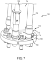
- FIG. 7 is a perspective view of an embodiment of a riser segment 700 including auxiliary lines 702 and a main line 704.
- a flange 706 is coupled to the main line 704 and the auxiliary lines 702 extend through respective apertures 708 forming in the flange 706.
- a coupling assembly 710 joins auxiliary line segments together.
- an outer diameter 712 of the coupling assembly 710 is larger than a diameter 714 of the apertures 708. Accordingly, axial movement may be blocked in at least one direction.
- other segments may have diameters less than the apertures 708, as described above, to facilitate installation of various components.
- one or more components of the coupling assembly 710 may be arranged at a higher elevation 716 than an associated fastener 718 of the flange 706. Accordingly, in embodiments, one or more torqueing tools may be utilized to make or break connections of the coupling assembly 710.
- the coupling assembly may include one or more components, such as a split ring and a separately coupled sleeve, for example.
- the split ring and/or the sleeve may include threads to facilitate coupling to one another, as well as other components of the system.
- the split ring is arranged coaxially with the pin and disposed radially outward of the pin.
- the split ring may include one or more fasteners to couple segments together and/or one or more fasteners to couple directly to pin.
Landscapes
- Engineering & Computer Science (AREA)
- General Engineering & Computer Science (AREA)
- Mechanical Engineering (AREA)
- Mining & Mineral Resources (AREA)
- Life Sciences & Earth Sciences (AREA)
- Geology (AREA)
- Fluid Mechanics (AREA)
- Environmental & Geological Engineering (AREA)
- Physics & Mathematics (AREA)
- General Life Sciences & Earth Sciences (AREA)
- Geochemistry & Mineralogy (AREA)
- Earth Drilling (AREA)
- Mutual Connection Of Rods And Tubes (AREA)
- Small-Scale Networks (AREA)
Description
- This application claims priority to
U.S. Patent Application No. 16/369,354 filed March 29, 2019 - This disclosure relates in general to oil and gas service methodologies utilizing tools, and in particular, to systems for providing threaded riser auxiliary lines.
- In oil and gas production, drilling and recovery may be conducted at sea, which may include platforms or rigs having risers to adjust a position of the platform in response to movement of the ocean. The risers may provide an upward force on the platform to enable the platform to raise and lower along with the sea, thereby reducing the likelihood of causing excess strain and movement to components of the drilling system. In various embodiments, the riser tensioners may include hydraulic cylinders that receive a high pressure fluid to apply the force to the platform. Furthermore, the risers may include auxiliary lines to transport various fluids to different portions of the drilling operation. For example, hydraulic fluid may be transmitted to subsea components, such as a blowout preventer (BOP). In operation, the auxiliary lines may include box and pin connectors to couple the pressure containing portions of the line together. In the event the connection is damaged, the riser is generally taken offline and sent to shore for repairs. This causes undesirable delays and is costly to producers.
US 2011/227336 A1 describes a coupling arrangement for connection of two pipe elements, comprising external threads on a first pipe element and a second pipe element carrying a radially movable locking member with external locking profiles. A connection sleeve with internal threads is threaded onto the external threads and internal locking profiles are engaged with the external locking profiles. The connection sleeve is moved in a first axial direction towards the first pipe element by rotation on the external threads while its internal profiles are in an intermediate engagement with the external profiles, until the movement is limited by abutting faces of the internal and external profiles, when possible axial clearances have been closed due to the first axial movement. The abutting faces exhibit an inclination resulting in a pull of the connection sleeve towards an axial direction opposite of the first direction, when the external locking profiles are moved radially outwards from the intermediate engagement to a position of further engagement of the internal locking profiles. -
US 4 496 173 discloses a coupling for a marine riser. - Applicants recognized the problems noted above herein and conceived and developed embodiments of systems and methods, according to the present disclosure, for coupling auxiliary lines.
- According to the present disclosure, a system comprises a marine riser, having a central axis, an auxiliary line disposed radially outward from the marine riser about the central axis, wherein the auxiliary line is positioned circumferentially around the marine riser, and wherein the auxiliary line comprises a first pipe segment and a second pipe segment. The system further comprises a pin end of the first pipe segment, the pin end including a flange. The system also includes a box end of the second pipe segment, the box end having a recess configured to receive the pin end, a face of the box end abutting the flange when the pin end is installed within the recess. The system further includes a coupling assembly joining the first pipe segment to the second pipe segment, the coupling assembly includes a split ring arranged axially proximate the flange and a sleeve, wherein threads of the sleeve engage first mating threads on the split ring and second mating threads on the box end to secure the first pipe segment to the second pipe segment.
Embodiments of the system are defined in the dependent claims. - A coupling assembly for joining a first tubular segment to a second tubular segment is described herein. The coupling assembly, which does not form part of the claimed subject-matter, may be used in embodiments of the system of the present disclosure. The coupling assembly includes a split ring adapted to couple to the first tubular segment, the split ring including a threaded portion at a first outer diameter and an end having a second outer diameter, larger than the first outer diameter. The coupling assembly also includes a sleeve adapted to couple to the second tubular segment and the split ring, wherein the sleeve includes internal threads configured to couple to mating threads on the second tubular segment and to the threaded portion of the split ring.
- A method for coupling a first pipe segment to a second pipe segment is described herein. The method, which does not form part of the claimed subject-matter, may be used to provide embodiments of the system of the present disclosure. The method includes coupling a pin to the first pipe segment, the pin including a flange. The method also includes installing at least a portion of a coupling assembly to the first pipe segment, the coupling assembly arranged proximate the flange to axially restrict movement of at least a portion of the coupling assembly in at least one direction. The method further includes coupling a box to the second pipe segment. The method also includes engaging external threads of the box via internal threads of at least a portion of the coupling assembly. The method includes coupling the box to the pin via rotation of at least a portion of the coupling assembly.
- The present technology will be better understood on reading the following detailed description of non-limiting embodiments thereof, and on examining the accompanying drawings, in which:
-
FIG. 1 is a schematic side view of an embodiment of a riser joint, in accordance with embodiments of the present disclosure; -
FIG. 2 is a perspective view of an embodiment of a riser joint, in accordance with embodiments of the present disclosure; -
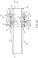
FIG. 3A is a schematic cross-sectional view of an embodiment of an auxiliary joint assembly, in accordance with embodiments of the present disclosure; -
FIG. 3B is a perspective view of an embodiment of an auxiliary joint assembly, in accordance with embodiments of the present disclosure; -
FIG. 4 is a schematic cross-sectional view of an embodiment of an auxiliary joint assembly, in accordance with embodiments of the present disclosure; -
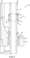
FIG. 5 is a schematic cross-sectional view of an embodiment of an auxiliary line configuration, in accordance with embodiments of the present disclosure; -
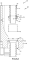
FIG. 6A is a schematic cross-sectional view of an embodiment of an installation scenario, in accordance with embodiments of the present disclosure; -
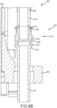
FIG. 6B is a schematic cross-sectional view of an embodiment of an installation scenario, in accordance with embodiments of the present disclosure; -
FIG. 7 is a perspective view of an embodiment of a riser joint, in accordance with embodiments of the present disclosure; and -
FIG. 8 is a flow chart of an embodiment of a method for installing an auxiliary line via a coupling assembly, which may be used to provide a system in accordance with embodiments of the present disclosure. - The foregoing aspects, features and advantages of the present technology will be further appreciated when considered with reference to the following description of preferred embodiments and accompanying drawings, wherein like reference numerals represent like elements. In describing the preferred embodiments of the technology illustrated in the appended drawings, specific terminology will be used for the sake of clarity. The present technology, however, is not intended to be limited to the specific terms used, and it is to be understood that each specific term includes equivalents that operate in a similar manner to accomplish a similar purpose.
- When introducing elements of various embodiments of the present invention, the articles a," "an," "the," and "said" are intended to mean that there are one or more of the elements. The terms "comprising," "including," and "having" are intended to be inclusive and mean that there may be additional elements other than the listed elements. Any examples of operating parameters and/or environmental conditions are not exclusive of other parameters/conditions of the disclosed embodiments. Additionally, it should be understood that references to "one embodiment", "an embodiment", "certain embodiments," or "other embodiments" of the present invention are not intended to be interpreted as excluding the existence of additional embodiments that also incorporate the recited features. Furthermore, reference to terms such as "above," "below," "upper", "lower","side", "front," "back," or other terms regarding orientation are made with reference to the illustrated embodiments and are not intended to be limiting or exclude other orientations.
- The present disclosure includes a coupling assembly for joining tubular sections together by reducing a number of components that include threads, which may be subject to environmental conditions that may cause corrosion or seizing. Adjacent pin stabs are coupled together via the coupling assembly where one of the pin stabs (the pin end) does not include threads while the other pin stab (the box end) does include threads. A split ring is coupled to the pin end and a threaded sleeve engages threads on both the split ring and the box end to couple the adjacent pin stabs. In various embodiments, components may be formed from different materials, for example materials having different strength properties. For example, components that are not exposed to fluid may be formed from non-NACE materials having improved strength factors, which may enable smaller components. Furthermore, installation may be improved by maintaining dimensions small enough to extend through associated flanges of marine risers and also enable torqueing tools without interfering with other equipment.
- Threading may be removed from a permanent pin component, which may desensitize the component from potential corrosion issues. In other words, threaded fittings may be arranged on components that are expected to be removed (or replaced). The system introduces flexibility via the introduction of a split ring and sleeve arrangement that may enable replacement of the auxiliary line for marine risers without removal of ancillary riser components such as buoyancy, clamp bands, and centralizers, for example. In various embodiments, components forming the present disclosure may be sized to enable torqueing tools onto the threaded components, thereby facilitating joining and releasing of the components. The inclusion of sizing to facilitate torqueing tools may enable breaking bonds formed when, for example, threads are rusted together. Furthermore, in various embodiments, certain components may be arranged to be cut (e.g., mechanical cutting, torch cutting, etc.) or otherwise decoupled from the permanent pin connection. As a result, if torqueing tools are unsuccessful in decoupling components, certain components may be removed in other ways, while leaving the permanent pin component in place. In various embodiments, components of the present disclosure are arranged in such a way that the highly stressed areas inhabit non-NACE components, which are not held to low-hardness (low- strength) requirements of NACE. As would be appreciated, NACE components refer to standards or criteria established by the NACE International. These standards are directed toward material properties, surface preparation techniques, coatings, and the like to reduce the likelihood of corrosion of materials in a variety of applications. NACE standards may provide recommendations for certain percentages of elements within alloy steels and the like that reduce the likelihood of corrosion or other material damage. For example, NACE MR0175/ISO 15156 gives requirements and recommendations for the selection and qualification of carbon and low-alloy steels, corrosion-resistant alloys, and other alloys for service in equipment used in oil and natural gas production and natural gas treatment plants in H2S-containing environments, whose failure could pose a risk to the health and safety of the public and personnel or to the equipment itself. However, inclusion of other elements may impact certain properties, such as material strength, which may decrease load ratings. Accordingly, components may be efficiently sized by using stronger materials at certain locations. This may reduce costs, reduce the size of the components, increase safety factors, and also be easier to source. It should be appreciated that, while embodiments of the present disclosure may refer to NACE or non-NACE components, that such components are not limited to these particular standards. Rather, referring to NACE and non-NACE components refers to materials having different degrees of corrosion resistance and/or different strength values.
-
FIG. 1 is a schematic side view of an embodiment of asegment 100 of a riser joint 102 that includesauxiliary lines 104 arranged radially outward from amain line 106 of the riser joint 102 and that are substantially parallel to themain line 106. The riser joint 102 may also be referred to as a Marine Drilling Riser and may formed at various lengths, such as between approximately 5 feet and 90 feet, or even longer. Theauxiliary lines 104 may be clamped along the sides of themain line 106 for transmitting drilling fluids and hydraulic fluids as needed for various components, such as blowout preventer (BOP) control. In various embodiments, there may be up to sixauxiliary lines 104 coupled to themain line 106. For example, individual lines may be for choke, for kill, for boost, for hydraulic controls, and for more specialized functions. In various embodiments, theauxiliary lines 104 include a pin end and abox end 108 to facilitate coupling betweendifferent sections 110 of theauxiliary lines 104. For example, theauxiliary lines 104 may be long and the lines may be broken into thesections 110 in order to enable repairs tocertain sections 110 without working on the entire length of theauxiliary line 104. As used herein, line may refer to a tubular or pipe-like connection to facilitate transmission of a liquid, gas, solid, or a combination thereof (which may be referred to herein as a "fluid") under pressure. - In operation, the pin end is inserted into a corresponding box end to form a pressure-containing connection between
different sections 110 of theauxiliary line 104. In various embodiments, thesections 110 may be welded together, for example at an interface between the pin and box ends. This welded connection may enable high-pressure transmission of fluids through the auxiliary lines. In various embodiments, the pressures within the lines may be approximately 138 MPa (20,000 pounds per square inch (psi)), however it should be appreciated that the pressure may be greater than or less than 138 MPa (20,000 psi). Accordingly, robust connections are utilized in order to reduce the likelihood of leaks. Additionally, external loads are transmitted through the auxiliary lines to efficiently distribute the tensile forces and bending moments through the riser system. Connections are designed to be sturdy enough to account for these load combinations while continuing to maintain pressure integrity. -
Sections 110 of theauxiliary line 104 may become damaged or otherwise unusable during operations, such as due to contact from outside forces, normal wear and tear, and the like. When theauxiliary lines 104 are damaged, theriser 102 is taken out of service and sent to shore for repairs because thesections 110 may be welded together. This process presents logistical challenges and costly operational delays. Systems and methods of the present disclosure provide a non-welded connection betweensections 110 of theauxiliary lines 104, thereby enabling repairs on the platform. That is, repairs without sending theriser 102 back to shore. As such, the logistical challenges may be substantially eliminated and the time and cost associated with the repairs or replacement may be reduced. -
FIG. 2 is an isometric view of an embodiment of ariser segment 200 that includes amain line 202 and a plurality ofauxiliary lines 204. It should be appreciated that the fiveauxiliary lines 204 are for illustrative purposes only and that, in various embodiments, more or fewerauxiliary lines 204 may be included. Theauxiliary lines 204 are arranged radially outward from themain line 202 with respect to anaxis 206 and positioned circumferentially about a circumference of themain line 202. Aflange 208 is coupled to themain line 202 and includesapertures 210 for receiving theauxiliary line 204. In various embodiments, theflange 208 may include additional couplings and/orfixtures 212 to facilitate securing theauxiliary line 204 to theflange 208. It should be appreciated that theauxiliary line 204 may have different diameters and include additional components, such as thrust columns, which will be described herein. -
FIG. 3A is a schematic cross-sectional side view of an embodiment of a joint 300 including acoupling assembly 302 to join afirst segment 304 to asecond segment 306. It should be appreciated that therespective segments respective segments - In various embodiments, the
first segment 304 and thesecond segment 306 are axially aligned along anaxis 308 such thatrespective bores first segment 304 and thesecond segment 306 are aligned. It should be appreciated that, while the illustrated bores 310, 312 have the same diameter in the illustrated embodiment, in other embodiments the diameters may not be equal. Each of therespective segment body portions axis 308 to form a tubular to enable fluid to pass through thebores segments segments - The illustrated
first segment 304 is the above-referenced permanent pin, in that the permanent pin may be designed to couple to the marine riser, such as the flange 208 (FIG. 2 ) and be seen as a permanent or semi-permanent fixture. When utilizing permanent herein, the permanent pin may refer to a pin that has a longer expected life than, for example, a joining replacement pin. In other words, between a permanent pin and a replacement pin, the replacement pin is preferentially removed during replacement or repair operations. - The
first segment 304 includes apin end 318 having afirst diameter 320 that extends for a firstaxial length 322. It should be appreciated that the firstaxial distance 322 may be particularly selected based on operating conditions and the like. For example, in various embodiments, the firstaxial length 322 may be a ratio or percentage of, for example, a length of thefirst segment 304. However, in other embodiments, the firstaxial length 322 may be selected based on other design conditions, such as segment diameter, anticipated operating conditions, and the like. - Arranged axially proximate the
pin end 318 is aflange 324. In various embodiments, theflange 324 may also be referred to as a shoulder or stop. In operation, theflange 324 may receive at least a portion of the tensile load applied to thefirst segment 304. Theflange 324 has asecond diameter 326 that is larger than thefirst diameter 320. While the illustrated embodiment includes atransition 328 between thepin end 318 and theflange 324, in the form of a sloped surface, it should be appreciated that thetransition 328 may be any shape, such as 90 degree bend or the like. Thetransition 328 may be utilized to gradually accommodate the difference in diameters between thefirst diameter 320 and thesecond diameter 326. - Continuing with the
first segment 304, anaxial section 330 having athird diameter 332 is arranged opposite theflange 324. In the illustrated embodiment, thethird diameter 332 is smaller than thesecond diameter 326 and also larger than thefirst diameter 320. However, it should be appreciated that, in other embodiments, thethird diameter 332 may be substantially equal to thesecond diameter 326. In various embodiments, theaxial section 330 may extend along a majority of a length of thefirst segment 304 such that theaxial section 330 maintains a substantially diameter along a majority of the length of thefirst segment 304. However in other embodiments, various other step downs or the like may be arranged along the length of thefirst segment 304, as particularly selected, to determine an outside diameter. - In various embodiments, the
axial section 330 includes aretainer 334. The retainer may be utilized to hold or otherwise secure a split ring or collar to an outsider diameter of thefirst segment 304 at a predetermined location. For example, in the illustrated embodiment, theretainer 334 includes agroove 336. In certain embodiments, the split ring or collar may include a feature that extends, at least partially, into thegroove 336 and may block or otherwise limit axial movement of the split ring or collar. For example, in certain embodiments, a set screw or the like may extend from an outside diameter of the split ring or collar into thegroove 336 such that axial movement is blocked. - The illustrated joint 300 forms an
interface 338 between thefirst segment 304 and thesecond segment 306 such that there may be at least one contact point between thefirst segment 304 and thesecond segment 306. Theinterface 338 may be formed at abox end 340 of thesecond segment 306 that includes arecess 342 that receives thepin end 318 of thefirst segment 304. In the illustrated embodiment, therecess 342 includesbox walls 344 at afourth diameter 346. Thefourth diameter 346 may be particularly selected based on thefirst diameter 320 to facilitate coupling between thefirst segment 304 and thesecond segment 306. In the illustrated embodiment, thebox 340 extends a secondaxial length 348 that is substantially equal to the firstaxial length 322, thereby receiving thepin 318. As illustrated, thebox 340 further includes aface 350 that contacts theflange 324 when thepin 318 is installed within therecess 342. Theface 350 is positioned on an axial surface of thebox 340 at afifth diameter 352, which is substantially equal to thesecond diameter 326. However it should be appreciated that, in other embodiments, thefifth diameter 352 may be larger than or smaller than thesecond diameter 326. However, as will be described below, it may be advantageous for thefifth diameter 352 to be substantially equal to thesecond diameter 326 so that a threaded sleeve may be utilized engage threads along thesecond diameter 326 to couple thesecond segment 306 to a collar arranged on thefirst segment 304. - In the illustrated embodiment, the
box wall 344 includes anannular recess 354, which receives aseal 356. Theseal 356 may be compressed when thefirst segment 304 is coupled to thesecond segment 306, thereby blocking fluid from flowing out of thebores seal 356 and therecess 354 are illustrated on thebox 340 in the illustrated embodiment, it should be appreciated that therecess 354 and theseal 356 may be arranged on thepin end 318 in other embodiments. Furthermore, the shape of theannular recess 354 is for illustrative purposes and it should be appreciated that, in various embodiments, theannular recess 354 may be shaped to accommodate one ormore seals 356 having a variety of geometries. - The illustrated embodiment includes the
coupling assembly 302 for joining thefirst segment 304 to thesecond segment 306. The illustratedcoupling assembly 302 includes asplit ring 358 and asleeve 360. In various embodiments, thesleeve 360 includesthreads 362 extending along at least a portion thereof. Thethreads 362 engagethreads 364 arranged on the second segment 306 (e.g., at the fifth diameter 352) and also threads 366 arranged on thesplit ring 358. Accordingly, thefirst segment 304 may be secured to thesecond segment 306 via thesleeve 360. - In the illustrated embodiment, the
split ring 358 includes the threads 366 at asixth diameter 368, which is substantially equal to thesecond diameter 326. As a result, thesleeve 360 may have a substantially constantseventh diameter 370 to facilitate coupling thefirst segment 304 to thesecond segment 306. Further illustrated on thesplit ring 358 is anend 372 having an eighth diameter 374 larger than thesixth diameter 368 in the illustrated embodiment. Theend 372 may be utilized as a stop to prevent thesleeve 360 from extending too far axially and exposing thethreads 364 on thesecond segment 306. In other words, theend 372 may block further movement of thesleeve 360 in at least one axial direction. In operation, theend 372 may be vertically lower than thesleeve 360, and as a result, gravity may assist with bringing thesleeve 360 toward and resting on theend 372. In other embodiments, however, theend 372 may be vertically higher than thesleeve 360. - As described above, in various embodiments the
end 372 includes one ormore apertures 376 to facilitate coupling thesplit ring 358 to thefirst segment 304. For example, set screws or pins may extend through theapertures 376 and into thegroove 336 to secure thesplit ring 358 to thefirst segment 304. Moreover, in various embodiments, thesplit ring 358 may include one or more fasteners to secure thesplit ring 358 to thefirst segment 304 without the use of additional coupling devices. Furthermore, in embodiments, one or more anti-rotation elements may be utilized to join thesleeve 360 and thesplit ring 358 directly together. For example, a pin may extend through thesleeve 360 and mate with a corresponding orifice of thesplit ring 358. - As will be described herein, in operation an outer diameter of the
coupling assembly 302 may be less than a diameter of one or more apertures in the flange (208) to enable installation of thecoupling assembly 302 through the flange. Furthermore, in various embodiments, thefifth diameter 352 may be less than a diameter of the one or more apertures in the flange (208) to enable installation. For example, thefirst segment 304 may be arranged in a spaced relationship (e.g., axially above) the aperture while thesecond segment 306 is installed into position through the aperture. - In various embodiments, different components of the joint 300 may be formed from different materials based on operating conditions. For example, in embodiments, the components of the
coupling assembly 302, such as thesplit ring 358 and thesleeve 360 may be formed from stronger, harder materials because these components are not subject to the same piping standards as thefirst segment 304 and thesecond segment 306. In other words, thesplit ring 358 and thesleeve 360 may be formed from non-NACE materials, thereby enabling stronger, harder materials such that the dimensions may be smaller than if NACE limited materials were used. Accordingly, thecoupling assembly 302 may be both smaller and more robust. -
FIG. 3B is a perspective view of an embodiment of thecoupling assembly 302 joining thefirst segment 304 to thesecond segment 306. In the illustrated embodiment, thesleeve 360 is coupled to thesplit ring 358, thereby securing thefirst segment 304 to the second segment. The illustratedsleeve 360 includes aslot 378 that received a pin and/or setscrew 380 of thesecond segment 306. In various embodiments, thepin 380 is rigidly coupled to thesecond segment 306 to block rotation of thesleeve 360 about theaxis 308 when thepin 380 is positioned within theslot 378. Accordingly, inadvertent decoupling of thesleeve 360, for example due to vibration or external forces, may be avoided. -
FIG. 4 is a cross-sectional side elevation view of an embodiment of a joint 400 including acoupling assembly 402. As described above, thesegments respective segments - In various embodiments, the
first segment 404 and thesecond segment 406 are axially aligned along anaxis 408 such thatrespective bores 410, 412 of thefirst segment 404 and thesecond segment 406 are aligned. It should be appreciated that, while the illustrated bores 410, 412 have the same diameter in the illustrated embodiment, in other embodiments the diameters may not be equal, as described above with respect to the embodiment illustrated inFIG. 3 . Each of therespective segment body portions axis 408 to form a tubular to enable fluid to pass through thebores 410, 412. As described above, various different sections of thesegments segments - The illustrated
first segment 404 is the above-referenced permanent pin, in that the permanent pin may be designed to couple to the marine riser, as described above, the permanent pin is not intended to be a reference a permanent component that cannot be removed, but rather, a component that is intended to be replaced less often than the replacement pin. - The
first segment 404 includes apin end 418 having a first diameter 420 that extends for a firstaxial length 422. It should be appreciated that the firstaxial distance 422 may be particularly selected based on operating conditions and the like. Arranged axially proximate thepin end 418 is aflange 424. In various embodiments, theflange 424 may also be referred to as a shoulder or stop. In operation, theflange 424 may receive at least a portion of the tensile load applied to thefirst segment 404. Theflange 424 has a second diameter 426 that is larger than the first diameter 420. While the illustrated embodiment includes a transition 428 between thepin end 418 and theflange 424, in the form of a sloped surface, it should be appreciated that the transition 428 may be any shape, such as 90 degree bend or the like, as described above. - The
first segment 404 also includes anaxial section 430 having athird diameter 432 arranged opposite theflange 424. In the illustrated embodiment, thethird diameter 432 is smaller than the second diameter 426 and also larger than the first diameter 420. However, it should be appreciated that, in other embodiments, thethird diameter 432 may be substantially equal to the second diameter 426. - In various embodiments, the
axial section 430 includes arecess 434 having ashoulder 436. Therecess 434 may be utilized to receive a split ring or collar to facilitate coupling thefirst segment 404 to thesecond segment 406, as will be described below. Theshoulder 436 may block axial movement of the split ring or collar along theaxis 408. - The illustrated joint 400 forms an
interface 438 between thefirst segment 404 and thesecond segment 406 such that there may be at least one contact point between thefirst segment 404 and thesecond segment 406. Theinterface 438 may be formed at abox end 440 of thesecond segment 406 that includes arecess 442 that receives thepin end 418 of thefirst segment 404. In the illustrated embodiment, therecess 442 includesbox walls 444 at afourth diameter 446. Thefourth diameter 446 may be particularly selected based on the first diameter 420 to facilitate coupling between thefirst segment 404 and thesecond segment 406. In the illustrated embodiment, thebox 440 extends a secondaxial length 448 that is substantially equal to the firstaxial length 422, thereby receiving thepin 418. As illustrated, thebox 440 further includes aface 450 that contacts theflange 424 when thepin 418 is installed within therecess 442. Theface 450 is positioned on an axial surface of thebox 440 at afifth diameter 452, which is substantially equal to the second diameter 426. However it should be appreciated that, in other embodiments, thefifth diameter 452 may be larger than or smaller than the second diameter 426. However, as will be described below, it may be advantageous for thefifth diameter 452 to be substantially equal to the second diameter 426 so that a threaded sleeve may be utilized engage threads along thefifth diameter 452 to couple thesecond segment 406 to a collar arranged on thefirst segment 404. - In the illustrated embodiment, the
box wall 444 includes anannular recess 454, which receives aseal 456. Theseal 456 may be compressed when thefirst segment 404 is coupled to thesecond segment 406, thereby blocking fluid from flowing out of thebores 410, 412. While theseal 456 and therecess 454 are illustrated on thebox 440 in the illustrated embodiment, it should be appreciated that therecess 454 and theseal 456 may be arranged on thepin end 418 in other embodiments. As described above, in various embodiments, therecess 454 may have a variety of different geometric arrangements to accommodate one ormore seals 456 having different geometries. - The illustrated embodiment includes the
coupling assembly 402 for joining thefirst segment 404 to thesecond segment 406. The illustratedcoupling assembly 402 includes a split ring 458 and asleeve 460. In various embodiments, thesleeve 460 includesthreads 462 extending along at least a portion thereof. Thethreads 462 engagethreads 464 arranged on the second segment 406 (e.g., at the fifth diameter 452) and alsothreads 466 arranged on the split ring 458. Accordingly, thefirst segment 404 may be secured to thesecond segment 406 via thesleeve 460. - In the illustrated embodiment, the split ring 458 includes the
threads 466 at asixth diameter 468, which is substantially equal to the second diameter 426. As a result, thesleeve 460 may have a substantially constantseventh diameter 470 to facilitate coupling thefirst segment 404 to thesecond segment 406. Further illustrated on the split ring 458 is anend 472 having aneighth diameter 474 larger than thesixth diameter 468 in the illustrated embodiment. Theend 472 may be utilized as a stop to prevent thesleeve 460 from extending too far axially along thefirst segment 404. In other words, theend 472 may block further movement of thesleeve 460 in at least one axial direction. However, in various embodiments, a length of thesleeve 460 may be particularly selected to expose or fully cover thethreads 464. In operation, theend 472 may be vertically lower than thesleeve 460, and as a result, gravity may assist with bringing thesleeve 460 toward and resting on theend 472. In other embodiments, however, theend 472 may be vertically higher than thesleeve 460. - As described above, in various embodiments the
end 472 includes one or more apertures 476 to facilitate coupling the split ring 458 to thefirst segment 404. For example, fasteners may extend through the illustrated apertures 476 to secure the split components of the split ring 458 together. As described above, in certain embodiments, additional fasteners may be utilized to further couple the split ring 458 to thefirst segment 404, such as a set screw or the like. - As described above, in operation an outer diameter of the
coupling assembly 402 may be less than a diameter of one or more apertures in the flange (FIG. 2 ) to enable installation of thecoupling assembly 402 through the flange. Furthermore, in various embodiments, thefifth diameter 452 may be less than a diameter of the one or more apertures in the flange (FIG. 2 ) to enable installation. For example, thefirst segment 404 may be arranged in a spaced relationship with respect to (e.g., axially above) the aperture while thesecond segment 406 is installed into position through the aperture. -
FIG. 5 is a cross-sectional view of an embodiment of ariser segment 500 including anauxiliary line 502 coupled to aflange 504 extending from amain line 506. In the illustrated embodiment, theauxiliary line 502 extends through anaperture 508 of theflange 504 and includes alock nut 510 that secures theauxiliary line 502 to theflange 504. In the illustrated embodiment, apipe segment 512 is coupled to apin 514. For example, thepin 514 may be welded to an end of thepipe segment 512, as shown in the illustrated embodiment. It should be appreciated that such a connection may be formed prior to installation of theauxiliary line 502, for example, at the shore, thereby reducing the likelihood of a welding operation on the offshore platform. - The illustrated
pin 512 is coupled to abox 516 via acoupling assembly 518, as described above with respect toFIGS. 3 and4 . Thecoupling assembly 518 includes the above-describedsplit ring 520 andsleeve 522. The illustrated embodiment includes the coupling assembly described inFIG. 3 , however, it should be appreciated that the coupling assembly described inFIG. 4 , as well as other configurations described herein, may also be utilized in the arrangement illustrated inFIG. 5 . - As described above, the
box 516 includes anouter diameter 524, which is smaller than anaperture diameter 526. As a result, thebox 516 may be installed by passing through theaperture 508, thereby reducing work to install thebox 516. For example, thesplit ring 520 may be installed on thepin 514 and thesleeve 522 may be arranged in position axially higher than theflange 504. Thereafter, thebox 516 may pass through theaperture 508 and engage the sleeve 522 (e.g., via the mating threads described above). In certain embodiments, other dimensions of theauxiliary line 502 and related components may be particularly selected based on the dimensions of other components of theflange 504. For example, theouter diameter 524 may be selected based, at least in part, on theaperture diameter 526 and other dimensions may be based on tooling or other considerations. - It should be appreciated that the embodiment illustrated in
FIG. 5 has been simplified for discussion purposes and that other components have been eliminated for clarity with this discussion. For example, various fasteners, thrust columns, and the like have been omitted. -
FIGS. 6A and6B are cross-sectional views of an embodiment of aninstallation scenario 600 where embodiments of the present disclosure may be installed on ariser segment 602. It should be appreciated that the installation procedure utilized may be done as a retrofit application (e.g., an existing line is modified to include, for example, a pin) and/or as new installation. - In
FIG. 6A , theriser segment 602 includes anauxiliary line 604 and amain line 606 having aflange 608 extending radially outward. In the illustrated embodiment, theauxiliary line 604 includes afirst segment 610 and asecond segment 612 that will be joined together via acoupling assembly 614. The illustratedfirst segment 610 includes apin 616, which as described above, may be described as a permanent pin. Thesecond segment 612 includes abox end 618, which as described above, may also be described as a replaceable pin. - In the illustrated embodiment, the
coupling assembly 614 includes asplit ring 620 and asleeve 622. Theillustrated split ring 620 is coupled to thepin 616 and aflange 624 of thepin 616 blocks axial movement of thesplit ring 620 in at least one direction (e.g., a downward direction relative to the page). In the illustrated embodiment, thesleeve 622 is arranged between thefirst segment 610 and thesecond segment 612. As will be described below, thesleeve 622 may be coupled to thesecond segment 612 prior to coupling thefirst segment 610 to thesecond segment 612. This installation procedure may prevent rotation of the seals arranged within the box end of the second segment 612 (FIGS. 3A and4 ) from rotating over the seal surface, and rather, enables the seals to be pulled straight over thepin 616 of thefirst segment 610. As described above, in various embodiments,threads 626 of thesleeve 622 may engagethreads 628 of thesplit ring 620 to couple thefirst segment 610 to thesecond segment 612. - As shown, an
outer diameter 630 of thebox 618 is less than adiameter 632 of anaperture 634 of theflange 624. As a result, thebox 618 may pass up through theaperture 634 for installation and connection to thepin 616. In this manner, thebox end 618 may be installed and/or removed without cutting or otherwise taking parts out of service. For example, in embodiments where the initial installation is made via the illustrated box and pin connector, thebox end 618 may be decoupled from thepin 616 and then removed in the same manner. As a result, down time for maintenance on theauxiliary line 604 may be reduced. -
FIG. 6B illustrates thebox end 618 engaging the illustratedsleeve 622. In various embodiments,threads 636 engage thethreads 626 of thesleeve 622 to facilitate coupling thepin 616 to thebox end 618. In embodiments, thesleeve 622 may be secured to thebox end 618 after thesleeve 612 is coupled to thebox end 618. For example, while not illustrated inFIG. 6B , anti-rotation features, such as the feature illustrated inFIG. 3B , may be utilized. As a result, thesleeve 622 may be threaded into place on thebox end 618 and then secured via a screw, pin, or other anti-rotation feature. In various embodiments, one or more dimensions may enable tools, such as torqueing tools, to facilitate forming the connection between thebox end 618 and thepin 616. For example, rotation of thesplit ring 620 may enable coupling between thebox end 618 and thepin 616 via rotation about thefirst segment 610. In certain embodiments, thesecond segment 612 and/or thesleeve 622 may rotate during installation, for example, in response to a torque applied to thesleeve 622. Accordingly, thefirst segment 610 may be joined to thesecond segment 612 via thecoupling assembly 614. As described above, an installation where thesplit ring 620 rotates may reduce the likelihood of the seals (FIGS. 3 A and4 ) rotating during installation. Thereafter, if disassembly is necessary, the threaded connection may be broken, one or more components may be cut, or the like. -
FIG. 7 is a perspective view of an embodiment of ariser segment 700 includingauxiliary lines 702 and amain line 704. In the illustrated embodiment, aflange 706 is coupled to themain line 704 and theauxiliary lines 702 extend throughrespective apertures 708 forming in theflange 706. In the illustrated embodiment, acoupling assembly 710 joins auxiliary line segments together. In the illustrated embodiment, anouter diameter 712 of thecoupling assembly 710 is larger than adiameter 714 of theapertures 708. Accordingly, axial movement may be blocked in at least one direction. However, as illustrated, other segments may have diameters less than theapertures 708, as described above, to facilitate installation of various components. Furthermore, as illustrated, one or more components of thecoupling assembly 710 may be arranged at ahigher elevation 716 than an associated fastener 718 of theflange 706. Accordingly, in embodiments, one or more torqueing tools may be utilized to make or break connections of thecoupling assembly 710. -
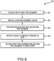
FIG. 8 is a flow chart of an example of amethod 800 for installing an auxiliary line to a riser segment. It should be appreciated that for this method and other methods described herein that there may be more or fewer steps. Furthermore, the steps may be performed in any order or in parallel, unless otherwise specifically stated. In this example, a pin is coupled to a first pipe segment (block 802), for example to a pipe segment forming at least a portion of an auxiliary line. In various embodiments, the pin may be retrofit by coupling to an existing auxiliary line that is taken out of service. Additionally, in embodiments, the pin may be coupled or otherwise formed directly onto the pipe segment. - The method continues with by installing at least a portion of a coupling assembly to the pin (block 804). In various embodiments, the coupling assembly may include one or more components, such as a split ring and a separately coupled sleeve, for example. The split ring and/or the sleeve may include threads to facilitate coupling to one another, as well as other components of the system. In various embodiments, the split ring is arranged coaxially with the pin and disposed radially outward of the pin. The split ring may include one or more fasteners to couple segments together and/or one or more fasteners to couple directly to pin.
- In embodiments, the pin may be arranged adjacent to a box (block 806) that may be coupled to a second pipe segment. For example, the box may include an opening or recess to receive at least a portion of the pin. In certain embodiments, the sleeve may be arranged to receive an outer diameter of the box, which may also include external threads that mate with the threads of the sleeve. The sleeve may be coupled to the box before the sleeve is coupled to mating threads of the split ring. The split ring may be rotated to engage the box threads (block 808). For example, the split ring may rotate about (or with) the split ring to bring the recess of the box toward the pin. In this manner, the auxiliary line may be formed from a series of segments each having a box and pin connector that includes the coupling assembly. It should be appreciated that, in other embodiments, the sleeve may rotate and the split ring may be stationary. Such a configuration may be easier to repair and/or replace while on the platform due to the elimination of various welded connections between the segments of the auxiliary line. Furthermore, as described above, various components may be formed from non-NACE materials and, as a result, may be formed from higher strength materials that facilitate smaller components.
- Although the technology herein has been described with reference to particular embodiments, it is to be understood that these embodiments are merely illustrative of the principles and applications of the present technology. It is therefore to be understood that numerous modifications may be made to the illustrative embodiments and that other arrangements may be devised without departing from the scope of the present application as determined by the appended claims.
Claims (9)
- A system comprising:a marine riser (106; 202; 506; 606; 704), having a central axis (206);an auxiliary line (104; 204; 502; 604; 702) disposed radially outward from the marineriser (106; 202; 506; 606; 704) about the central axis,wherein the auxiliary line (104; 204; 502; 604; 702) is positioned
circumferentially around the marine riser (106; 202; 506; 606; 704), andwherein the auxiliary line (104; 204; 502; 604; 702) comprises a first pipe segment (304; 404) and a second pipe segment (306; 406);a pin end (318; 418) of the first pipe segment (304; 404), the pin end (318; 418) including a flange (324; 424);a box end (340; 440) of the second pipe segment (306; 406), the box end (340; 440) having a recess (342; 442) configured to receive the pin end (318; 418), a face (350; 450) of the box end (340; 440) abutting the flange (324; 424) when the pin end (318; 418) is installed within the recess (424; 442); anda coupling assembly (302; 402) joining the first pipe segment (304; 404) to the second pipe segment (306; 406), the coupling assembly (302; 402) comprising a split ring (358; 458) arranged axially proximate the flange (324; 424) and a sleeve (360; 460), wherein threads (362; 462) of the sleeve (360; 460) engage first mating threads (366; 466) on the split ring (358, 458) and second mating threads (364; 464) on the box end (340; 440) to secure the first pipe segment (304; 404) to the second pipe segment (306; 406). - The system of claim 1, wherein the box end (340; 440) includes an axial recess (354; 454) that receives a seal (356; 456), the axial recess (354; 454) arranged proximate the pin end (318; 418) when the pin end (318; 418) is installed in the box end (340; 440).
- The system of claim 1, wherein the flange (324; 424) includes a shoulder, the shoulder abutting the split ring (358; 458) opposite the face (350; 450) of the box end (340; 440) to restrict axial movement of the split ring (358; 458) in at least one direction.
- The system of claim 1, wherein both the split ring (358; 458) and the sleeve (360; 460) are non-threadingly engaged with the pin end (318; 418).
- The system of claim 1, wherein a diameter (326; 426) of the flange (324; 424) is larger than a diameter (332; 432) of a proximate pin end section.
- The system of claim 1, wherein the coupling assembly (302; 402) and the box end (340; 440) are formed from different materials, wherein materials forming the coupling assembly (302; 402) have at least one of a higher hardness or a higher strength than materials forming the box end (340; 440).
- The system of claim 1, wherein an outside diameter (352; 452) of the box end (340; 440) and an outside diameter (324 ; 426) of the flange (324 ; 424) are substantially equal and the sleeve (360 ; 460) is arranged radially outward of at least a portion of the box end (340 ; 440) and the flange (324 ; 424).
- The system of claim 1, wherein the split ring (358 ; 458) is coupled to the pin end (318; 418) via a fastener.
- The system of claim 1, wherein the split ring (358 ; 458) is arranged within a recess (434) formed in the pin end (318), the recess (434) including a shoulder (436) blocking axial movement of the split ring (358 ; 458) in at least one direction.
Applications Claiming Priority (2)
| Application Number | Priority Date | Filing Date | Title |
|---|---|---|---|
| US16/369,354 US11555564B2 (en) | 2019-03-29 | 2019-03-29 | System and method for auxiliary line connections |
| PCT/US2020/024817 WO2020205389A1 (en) | 2019-03-29 | 2020-03-26 | System and method for auxiliary line connections |
Publications (3)
| Publication Number | Publication Date |
|---|---|
| EP3947894A1 EP3947894A1 (en) | 2022-02-09 |
| EP3947894A4 EP3947894A4 (en) | 2023-02-22 |
| EP3947894B1 true EP3947894B1 (en) | 2024-07-03 |
Family
ID=72604228
Family Applications (1)
| Application Number | Title | Priority Date | Filing Date |
|---|---|---|---|
| EP20784483.8A Active EP3947894B1 (en) | 2019-03-29 | 2020-03-26 | System and method for auxiliary line connections |
Country Status (6)
| Country | Link |
|---|---|
| US (1) | US11555564B2 (en) |
| EP (1) | EP3947894B1 (en) |
| CN (1) | CN113646504A (en) |
| BR (1) | BR112021019250A2 (en) |
| NO (1) | NO20211196A1 (en) |
| WO (1) | WO2020205389A1 (en) |
Families Citing this family (2)
| Publication number | Priority date | Publication date | Assignee | Title |
|---|---|---|---|---|
| US20220341530A1 (en) * | 2021-04-27 | 2022-10-27 | Oceaneering International, Inc. | Sealing member for repairing a pipeline and method of use |
| US12222054B2 (en) * | 2022-07-06 | 2025-02-11 | Spm Oil & Gas Inc. | Swivel assembly formed of a corrosion-resistant material |
Family Cites Families (55)
| Publication number | Priority date | Publication date | Assignee | Title |
|---|---|---|---|---|
| US944877A (en) * | 1909-06-08 | 1909-12-28 | Ernest August Koschinski | Coupling. |
| US1016620A (en) * | 1910-07-06 | 1912-02-06 | John Gapp | Pipe-coupling. |
| US1186325A (en) * | 1915-07-27 | 1916-06-06 | Leslie Company | Coupling. |
| US1913030A (en) * | 1931-06-17 | 1933-06-06 | Hux Frank | Packer attaching means |
| US2342834A (en) * | 1943-01-18 | 1944-02-29 | David O Brant | Composite coupling |
| US2443394A (en) * | 1943-05-26 | 1948-06-15 | Clair Camille Clare Sprankl Le | Coupling for hoses and pipes |
| US3345084A (en) | 1965-02-08 | 1967-10-03 | Ventura Tool Company | Pipe tool joints |
| US3692336A (en) | 1970-10-27 | 1972-09-19 | Wavin Bv | Pipe construction |
| US4043575A (en) | 1975-11-03 | 1977-08-23 | The Rucker Company | Riser connector |
| US4209193A (en) | 1977-05-17 | 1980-06-24 | Vetco, Inc. | Rigid connector for large diameter pipe |
| US4291906A (en) * | 1979-10-19 | 1981-09-29 | Donbavand Martin H | Device for locking and sealing standard cone-socket joints for laboratory apparatus |
| US4487434A (en) * | 1979-12-19 | 1984-12-11 | Hydril Company | Union-type coupling for marine drilling riser pipe |
| US4374595A (en) | 1980-06-16 | 1983-02-22 | Hughes Tool Company | Metal to metal sealed joint for tubing string |
| US4496173A (en) | 1980-08-28 | 1985-01-29 | Hydril Company | Threaded coupling |
| US4830408A (en) | 1981-06-05 | 1989-05-16 | Dril-Quip, Inc. | Connector assembly |
| FR2557194B1 (en) | 1983-12-23 | 1986-05-16 | Creusot Loire | QUICK CONNECTION FOR OIL DRILL EXTENSION TUBE |
| US4708513A (en) | 1985-09-06 | 1987-11-24 | Hydril Company | Fatigue resistant coupling for tubular members |
| US4691944A (en) * | 1986-05-22 | 1987-09-08 | The Boeing Company | Tubing connector |
| US4775008A (en) * | 1987-01-05 | 1988-10-04 | Dowell Schlumberger Incorporated | Adjustable cement head manifold |
| US4921284A (en) * | 1989-04-28 | 1990-05-01 | Fmc Corporation | High strength split clamp for pipe flanges |
| US5176409A (en) * | 1989-11-11 | 1993-01-05 | Dixie Iron Works | High pressure pipe coupling |
| US5879030A (en) | 1996-09-04 | 1999-03-09 | Wyman-Gordon Company | Flow line coupling |
| GB9710440D0 (en) * | 1997-05-22 | 1997-07-16 | Apex Tubulars Ltd | Improved marine riser |
| US6106024A (en) | 1998-06-04 | 2000-08-22 | Cooper Cameron Corporation | Riser joint and apparatus for its assembly |
| US6419277B1 (en) * | 1999-10-29 | 2002-07-16 | Hydril Company | Conduit section having threaded section connectors and external conduits attached thereto |
| GB0004212D0 (en) | 2000-02-23 | 2000-04-12 | Plexus Ocean Syst Ltd | Pipe joint |
| US6857668B2 (en) | 2000-10-04 | 2005-02-22 | Grant Prideco, L.P. | Replaceable corrosion seal for threaded connections |
| US7055870B2 (en) * | 2001-07-12 | 2006-06-06 | Hayes Jr Frank F | Molded flare assembly |
| US20080129045A1 (en) * | 2001-12-25 | 2008-06-05 | Mirai Industry Co., Ltd. | Water pipe end structure and connection therefor |
| US7231983B2 (en) * | 2004-01-06 | 2007-06-19 | Fmc Technologies, Inc. | Split locking ring for wellhead components |
| US7434848B2 (en) * | 2005-05-12 | 2008-10-14 | Boyd Anthony R | Threaded tubular connection having interlocking tubular end structures |
| US7686342B2 (en) * | 2005-12-16 | 2010-03-30 | Vetco Gray Inc. | Pipe connector and torque tool |
| BRPI0810610B1 (en) | 2007-04-27 | 2018-12-04 | Alcoa Inc | riser section for offshore metal drilling and riser section for offshore drilling for oil or other fossil fuels |
| US7984932B2 (en) * | 2007-12-19 | 2011-07-26 | Stinger Wellhead Protection, Inc. | Threaded union for tubulars used in high-pressure fluid applications |
| GB0816171D0 (en) | 2008-09-05 | 2008-10-15 | Aker Subsea Ltd | Tool and method for applying a pre-load to a pair of pipes or other elongate members |
| NO329147B1 (en) * | 2008-12-15 | 2010-08-30 | Aker Subsea As | Coupling arrangement and method of biased coupling |
| BRPI1013945A2 (en) | 2009-05-04 | 2016-04-05 | Cameron Int Corp | auxiliary aluminum lines for drilling riser |
| FR2946082B1 (en) * | 2009-05-29 | 2011-05-20 | Inst Francais Du Petrole | UPLINK COLUMN WITH ADJUSTABLE AUXILIARY PIPES. |
| FR2950924B1 (en) | 2009-10-07 | 2011-10-28 | Inst Francais Du Petrole | UPLANT COLUMN WITH RIGID AUXILIARY PIPES AND DECAL CONNECTORS |
| FR2956694B1 (en) | 2010-02-23 | 2012-02-24 | Inst Francais Du Petrole | UPLINK COLUMN CONNECTOR WITH FLANGES AND EXTERNAL LOCKING RING |
| GB2478917B (en) | 2010-03-22 | 2015-06-03 | Weatherford Uk Ltd | Connector |
| NO334241B1 (en) | 2011-05-18 | 2014-01-20 | Aker Subsea As | coupling device |
| US20130161021A1 (en) * | 2011-12-23 | 2013-06-27 | Stephen J. Makosey | Compression coupling for pipes subjected to tension loads and associated methods |
| US10087687B2 (en) | 2012-04-02 | 2018-10-02 | Cameron International Corporation | Seal sub system |
| US9022125B2 (en) | 2012-11-30 | 2015-05-05 | National Oilwell Varco, L.P. | Marine riser with side tension members |
| WO2014179538A1 (en) | 2013-05-03 | 2014-11-06 | Ameriforge Group Inc. | Large-width/diameter riser segment lowerable through a rotary of a drilling rig |
| NO336800B1 (en) | 2013-09-16 | 2015-11-02 | Aker Subsea As | coupling device |
| US9453375B2 (en) * | 2013-12-18 | 2016-09-27 | Cameron International Corporation | Riser with slim pin auxiliary line |
| MY184129A (en) | 2014-09-12 | 2021-03-19 | Single Buoy Moorings | Dynamic riser mechanical connector |
| CA2965531C (en) * | 2014-11-18 | 2021-03-23 | Weatherford Tehcnology Holdings, Llc | Annular isolation device for managed pressure drilling |
| US10480696B2 (en) * | 2015-12-01 | 2019-11-19 | Forum Us, Inc. | Locking collar quick union connection |
| WO2017106702A1 (en) * | 2015-12-18 | 2017-06-22 | Nelco Energy Services Llc | Non-preloaded threaded pipe connection for temporary high pressure piping |
| US10053923B2 (en) * | 2016-04-29 | 2018-08-21 | Forum Us, Inc. | Enhanced union connection |
| US10808871B2 (en) * | 2016-12-13 | 2020-10-20 | Cantex International, Inc. | High pressure flowline union |
| FR3063513B1 (en) | 2017-03-03 | 2019-04-12 | IFP Energies Nouvelles | METHOD FOR EVOLVING A CONNECTOR ASSEMBLING TWO RUNNERS OF AN UPPER COLUMN USING A REMOVABLE LOCKING RING |
-
2019
- 2019-03-29 US US16/369,354 patent/US11555564B2/en active Active
-
2020
- 2020-03-26 WO PCT/US2020/024817 patent/WO2020205389A1/en not_active Ceased
- 2020-03-26 CN CN202080025589.4A patent/CN113646504A/en active Pending
- 2020-03-26 EP EP20784483.8A patent/EP3947894B1/en active Active
- 2020-03-26 NO NO20211196A patent/NO20211196A1/en unknown
- 2020-03-26 BR BR112021019250A patent/BR112021019250A2/en not_active IP Right Cessation
Also Published As
| Publication number | Publication date |
|---|---|
| EP3947894A4 (en) | 2023-02-22 |
| CN113646504A (en) | 2021-11-12 |
| EP3947894A1 (en) | 2022-02-09 |
| US11555564B2 (en) | 2023-01-17 |
| US20200309292A1 (en) | 2020-10-01 |
| NO20211196A1 (en) | 2021-10-06 |
| BR112021019250A2 (en) | 2021-11-30 |
| WO2020205389A1 (en) | 2020-10-08 |
Similar Documents
| Publication | Publication Date | Title |
|---|---|---|
| RU2552638C2 (en) | Fitting with mechanical securing for operation in acid environment | |
| US9127525B2 (en) | Multi-component C-ring coupling | |
| US10156305B2 (en) | Pipe joint | |
| US20090160186A1 (en) | Threaded union for tubulars used in high-pressure fluid applications | |
| US20020079693A1 (en) | Remote articulated connector | |
| EP3025083B1 (en) | Improvements in and relating to pipe coupling | |
| AU2008245509A1 (en) | Method and apparatus for connecting drilling riser strings and compositions thereof | |
| CA2615294C (en) | Threaded union for tubulars used in high-pressure fluid applications | |
| US11555564B2 (en) | System and method for auxiliary line connections | |
| US12140260B2 (en) | Pipeline spool piece seal assembly and method of use | |
| WO2009103995A1 (en) | Coupling | |
| US10738541B2 (en) | System and method for threaded riser auxiliary lines | |
| MX2013012073A (en) | Apparatus and methods for splicing conduits and hoses subsea. | |
| EP3405644B1 (en) | Pipe coupling | |
| US9725966B2 (en) | Riser system | |
| KR20250116750A (en) | Hang-off device for end fitting of subsea pipe | |
| Warren | Building In Cost Saving-Diver Reconnectable Umbilical Weak Link Protection System | |
| GB2586308A (en) | Pipe coupling | |
| CA3072871A1 (en) | Bend restrictor |
Legal Events
| Date | Code | Title | Description |
|---|---|---|---|
| STAA | Information on the status of an ep patent application or granted ep patent |
Free format text: STATUS: THE INTERNATIONAL PUBLICATION HAS BEEN MADE |
|
| PUAI | Public reference made under article 153(3) epc to a published international application that has entered the european phase |
Free format text: ORIGINAL CODE: 0009012 |
|
| STAA | Information on the status of an ep patent application or granted ep patent |
Free format text: STATUS: REQUEST FOR EXAMINATION WAS MADE |
|
| 17P | Request for examination filed |
Effective date: 20211029 |
|
| AK | Designated contracting states |
Kind code of ref document: A1 Designated state(s): AL AT BE BG CH CY CZ DE DK EE ES FI FR GB GR HR HU IE IS IT LI LT LU LV MC MK MT NL NO PL PT RO RS SE SI SK SM TR |
|
| DAV | Request for validation of the european patent (deleted) | ||
| DAX | Request for extension of the european patent (deleted) | ||
| REG | Reference to a national code |
Ref country code: DE Ref legal event code: R079 Free format text: PREVIOUS MAIN CLASS: E21B0017042000 Ipc: F16L0015040000 Ref document number: 602020033423 Country of ref document: DE |
|
| A4 | Supplementary search report drawn up and despatched |
Effective date: 20230123 |
|
| RIC1 | Information provided on ipc code assigned before grant |
Ipc: F16L 15/00 20060101ALI20230117BHEP Ipc: E21B 17/08 20060101ALI20230117BHEP Ipc: F16L 15/08 20060101ALI20230117BHEP Ipc: F16L 15/04 20060101AFI20230117BHEP |
|
| GRAP | Despatch of communication of intention to grant a patent |
Free format text: ORIGINAL CODE: EPIDOSNIGR1 |
|
| STAA | Information on the status of an ep patent application or granted ep patent |
Free format text: STATUS: GRANT OF PATENT IS INTENDED |
|
| INTG | Intention to grant announced |
Effective date: 20240402 |
|
| RAP3 | Party data changed (applicant data changed or rights of an application transferred) |
Owner name: BAKER HUGHES OILFIELD OPERATIONS LLC |
|
| RIN1 | Information on inventor provided before grant (corrected) |
Inventor name: MYERS, GREGORY Inventor name: SWEENEY, KEVIN Inventor name: HAEBERLE, HUNTER S. Inventor name: BAKER, BRIAN S. |
|
| GRAS | Grant fee paid |
Free format text: ORIGINAL CODE: EPIDOSNIGR3 |
|
| GRAA | (expected) grant |
Free format text: ORIGINAL CODE: 0009210 |
|
| STAA | Information on the status of an ep patent application or granted ep patent |
Free format text: STATUS: THE PATENT HAS BEEN GRANTED |
|
| AK | Designated contracting states |
Kind code of ref document: B1 Designated state(s): AL AT BE BG CH CY CZ DE DK EE ES FI FR GB GR HR HU IE IS IT LI LT LU LV MC MK MT NL NO PL PT RO RS SE SI SK SM TR |
|
| REG | Reference to a national code |
Ref country code: CH Ref legal event code: EP |
|
| REG | Reference to a national code |
Ref country code: DE Ref legal event code: R096 Ref document number: 602020033423 Country of ref document: DE |
|
| REG | Reference to a national code |
Ref country code: GB Ref legal event code: 732E Free format text: REGISTERED BETWEEN 20240808 AND 20240814 |
|
| RAP2 | Party data changed (patent owner data changed or rights of a patent transferred) |
Owner name: HYDRIL USA DISTRIBUTION LLC |
|
| REG | Reference to a national code |
Ref country code: LT Ref legal event code: MG9D |
|
| REG | Reference to a national code |
Ref country code: NL Ref legal event code: MP Effective date: 20240703 |
|
| PG25 | Lapsed in a contracting state [announced via postgrant information from national office to epo] |
Ref country code: PT Free format text: LAPSE BECAUSE OF FAILURE TO SUBMIT A TRANSLATION OF THE DESCRIPTION OR TO PAY THE FEE WITHIN THE PRESCRIBED TIME-LIMIT Effective date: 20241104 |
|
| REG | Reference to a national code |
Ref country code: AT Ref legal event code: MK05 Ref document number: 1700137 Country of ref document: AT Kind code of ref document: T Effective date: 20240703 |
|
| PG25 | Lapsed in a contracting state [announced via postgrant information from national office to epo] |
Ref country code: NL Free format text: LAPSE BECAUSE OF FAILURE TO SUBMIT A TRANSLATION OF THE DESCRIPTION OR TO PAY THE FEE WITHIN THE PRESCRIBED TIME-LIMIT Effective date: 20240703 |
|
| PG25 | Lapsed in a contracting state [announced via postgrant information from national office to epo] |
Ref country code: PT Free format text: LAPSE BECAUSE OF FAILURE TO SUBMIT A TRANSLATION OF THE DESCRIPTION OR TO PAY THE FEE WITHIN THE PRESCRIBED TIME-LIMIT Effective date: 20241104 Ref country code: NL Free format text: LAPSE BECAUSE OF FAILURE TO SUBMIT A TRANSLATION OF THE DESCRIPTION OR TO PAY THE FEE WITHIN THE PRESCRIBED TIME-LIMIT Effective date: 20240703 |
|
| PG25 | Lapsed in a contracting state [announced via postgrant information from national office to epo] |
Ref country code: GR Free format text: LAPSE BECAUSE OF FAILURE TO SUBMIT A TRANSLATION OF THE DESCRIPTION OR TO PAY THE FEE WITHIN THE PRESCRIBED TIME-LIMIT Effective date: 20241004 Ref country code: FI Free format text: LAPSE BECAUSE OF FAILURE TO SUBMIT A TRANSLATION OF THE DESCRIPTION OR TO PAY THE FEE WITHIN THE PRESCRIBED TIME-LIMIT Effective date: 20240703 Ref country code: PL Free format text: LAPSE BECAUSE OF FAILURE TO SUBMIT A TRANSLATION OF THE DESCRIPTION OR TO PAY THE FEE WITHIN THE PRESCRIBED TIME-LIMIT Effective date: 20240703 |
|
| PG25 | Lapsed in a contracting state [announced via postgrant information from national office to epo] |
Ref country code: BG Free format text: LAPSE BECAUSE OF FAILURE TO SUBMIT A TRANSLATION OF THE DESCRIPTION OR TO PAY THE FEE WITHIN THE PRESCRIBED TIME-LIMIT Effective date: 20240703 |
|
| PG25 | Lapsed in a contracting state [announced via postgrant information from national office to epo] |
Ref country code: LV Free format text: LAPSE BECAUSE OF FAILURE TO SUBMIT A TRANSLATION OF THE DESCRIPTION OR TO PAY THE FEE WITHIN THE PRESCRIBED TIME-LIMIT Effective date: 20240703 |
|
| PG25 | Lapsed in a contracting state [announced via postgrant information from national office to epo] |
Ref country code: AT Free format text: LAPSE BECAUSE OF FAILURE TO SUBMIT A TRANSLATION OF THE DESCRIPTION OR TO PAY THE FEE WITHIN THE PRESCRIBED TIME-LIMIT Effective date: 20240703 Ref country code: IS Free format text: LAPSE BECAUSE OF FAILURE TO SUBMIT A TRANSLATION OF THE DESCRIPTION OR TO PAY THE FEE WITHIN THE PRESCRIBED TIME-LIMIT Effective date: 20241103 |
|
| PG25 | Lapsed in a contracting state [announced via postgrant information from national office to epo] |
Ref country code: HR Free format text: LAPSE BECAUSE OF FAILURE TO SUBMIT A TRANSLATION OF THE DESCRIPTION OR TO PAY THE FEE WITHIN THE PRESCRIBED TIME-LIMIT Effective date: 20240703 Ref country code: CZ Free format text: LAPSE BECAUSE OF FAILURE TO SUBMIT A TRANSLATION OF THE DESCRIPTION OR TO PAY THE FEE WITHIN THE PRESCRIBED TIME-LIMIT Effective date: 20240703 |
|
| PG25 | Lapsed in a contracting state [announced via postgrant information from national office to epo] |
Ref country code: ES Free format text: LAPSE BECAUSE OF FAILURE TO SUBMIT A TRANSLATION OF THE DESCRIPTION OR TO PAY THE FEE WITHIN THE PRESCRIBED TIME-LIMIT Effective date: 20240703 Ref country code: RS Free format text: LAPSE BECAUSE OF FAILURE TO SUBMIT A TRANSLATION OF THE DESCRIPTION OR TO PAY THE FEE WITHIN THE PRESCRIBED TIME-LIMIT Effective date: 20241003 |
|
| PG25 | Lapsed in a contracting state [announced via postgrant information from national office to epo] |
Ref country code: RS Free format text: LAPSE BECAUSE OF FAILURE TO SUBMIT A TRANSLATION OF THE DESCRIPTION OR TO PAY THE FEE WITHIN THE PRESCRIBED TIME-LIMIT Effective date: 20241003 Ref country code: PL Free format text: LAPSE BECAUSE OF FAILURE TO SUBMIT A TRANSLATION OF THE DESCRIPTION OR TO PAY THE FEE WITHIN THE PRESCRIBED TIME-LIMIT Effective date: 20240703 Ref country code: LV Free format text: LAPSE BECAUSE OF FAILURE TO SUBMIT A TRANSLATION OF THE DESCRIPTION OR TO PAY THE FEE WITHIN THE PRESCRIBED TIME-LIMIT Effective date: 20240703 Ref country code: IS Free format text: LAPSE BECAUSE OF FAILURE TO SUBMIT A TRANSLATION OF THE DESCRIPTION OR TO PAY THE FEE WITHIN THE PRESCRIBED TIME-LIMIT Effective date: 20241103 Ref country code: HR Free format text: LAPSE BECAUSE OF FAILURE TO SUBMIT A TRANSLATION OF THE DESCRIPTION OR TO PAY THE FEE WITHIN THE PRESCRIBED TIME-LIMIT Effective date: 20240703 Ref country code: GR Free format text: LAPSE BECAUSE OF FAILURE TO SUBMIT A TRANSLATION OF THE DESCRIPTION OR TO PAY THE FEE WITHIN THE PRESCRIBED TIME-LIMIT Effective date: 20241004 Ref country code: FI Free format text: LAPSE BECAUSE OF FAILURE TO SUBMIT A TRANSLATION OF THE DESCRIPTION OR TO PAY THE FEE WITHIN THE PRESCRIBED TIME-LIMIT Effective date: 20240703 Ref country code: ES Free format text: LAPSE BECAUSE OF FAILURE TO SUBMIT A TRANSLATION OF THE DESCRIPTION OR TO PAY THE FEE WITHIN THE PRESCRIBED TIME-LIMIT Effective date: 20240703 Ref country code: CZ Free format text: LAPSE BECAUSE OF FAILURE TO SUBMIT A TRANSLATION OF THE DESCRIPTION OR TO PAY THE FEE WITHIN THE PRESCRIBED TIME-LIMIT Effective date: 20240703 Ref country code: BG Free format text: LAPSE BECAUSE OF FAILURE TO SUBMIT A TRANSLATION OF THE DESCRIPTION OR TO PAY THE FEE WITHIN THE PRESCRIBED TIME-LIMIT Effective date: 20240703 Ref country code: AT Free format text: LAPSE BECAUSE OF FAILURE TO SUBMIT A TRANSLATION OF THE DESCRIPTION OR TO PAY THE FEE WITHIN THE PRESCRIBED TIME-LIMIT Effective date: 20240703 |
|
| REG | Reference to a national code |
Ref country code: DE Ref legal event code: R097 Ref document number: 602020033423 Country of ref document: DE |
|
| PG25 | Lapsed in a contracting state [announced via postgrant information from national office to epo] |
Ref country code: RO Free format text: LAPSE BECAUSE OF FAILURE TO SUBMIT A TRANSLATION OF THE DESCRIPTION OR TO PAY THE FEE WITHIN THE PRESCRIBED TIME-LIMIT Effective date: 20240703 Ref country code: SM Free format text: LAPSE BECAUSE OF FAILURE TO SUBMIT A TRANSLATION OF THE DESCRIPTION OR TO PAY THE FEE WITHIN THE PRESCRIBED TIME-LIMIT Effective date: 20240703 Ref country code: DK Free format text: LAPSE BECAUSE OF FAILURE TO SUBMIT A TRANSLATION OF THE DESCRIPTION OR TO PAY THE FEE WITHIN THE PRESCRIBED TIME-LIMIT Effective date: 20240703 |
|
| PGFP | Annual fee paid to national office [announced via postgrant information from national office to epo] |
Ref country code: NO Payment date: 20250327 Year of fee payment: 6 |
|
| PG25 | Lapsed in a contracting state [announced via postgrant information from national office to epo] |
Ref country code: EE Free format text: LAPSE BECAUSE OF FAILURE TO SUBMIT A TRANSLATION OF THE DESCRIPTION OR TO PAY THE FEE WITHIN THE PRESCRIBED TIME-LIMIT Effective date: 20240703 |
|
| PGFP | Annual fee paid to national office [announced via postgrant information from national office to epo] |
Ref country code: FR Payment date: 20250325 Year of fee payment: 6 |
|
| PG25 | Lapsed in a contracting state [announced via postgrant information from national office to epo] |
Ref country code: IT Free format text: LAPSE BECAUSE OF FAILURE TO SUBMIT A TRANSLATION OF THE DESCRIPTION OR TO PAY THE FEE WITHIN THE PRESCRIBED TIME-LIMIT Effective date: 20240703 Ref country code: SK Free format text: LAPSE BECAUSE OF FAILURE TO SUBMIT A TRANSLATION OF THE DESCRIPTION OR TO PAY THE FEE WITHIN THE PRESCRIBED TIME-LIMIT Effective date: 20240703 |
|
| PGFP | Annual fee paid to national office [announced via postgrant information from national office to epo] |
Ref country code: GB Payment date: 20250327 Year of fee payment: 6 |
|
| PLBE | No opposition filed within time limit |
Free format text: ORIGINAL CODE: 0009261 |
|
| STAA | Information on the status of an ep patent application or granted ep patent |
Free format text: STATUS: NO OPPOSITION FILED WITHIN TIME LIMIT |
|
| 26N | No opposition filed |
Effective date: 20250404 |
|
| PG25 | Lapsed in a contracting state [announced via postgrant information from national office to epo] |
Ref country code: SE Free format text: LAPSE BECAUSE OF FAILURE TO SUBMIT A TRANSLATION OF THE DESCRIPTION OR TO PAY THE FEE WITHIN THE PRESCRIBED TIME-LIMIT Effective date: 20240703 |
|
| REG | Reference to a national code |
Ref country code: DE Ref legal event code: R119 Ref document number: 602020033423 Country of ref document: DE |
|
| PG25 | Lapsed in a contracting state [announced via postgrant information from national office to epo] |
Ref country code: MC Free format text: LAPSE BECAUSE OF FAILURE TO SUBMIT A TRANSLATION OF THE DESCRIPTION OR TO PAY THE FEE WITHIN THE PRESCRIBED TIME-LIMIT Effective date: 20240703 |
|
| REG | Reference to a national code |
Ref country code: CH Ref legal event code: H13 Free format text: ST27 STATUS EVENT CODE: U-0-0-H10-H13 (AS PROVIDED BY THE NATIONAL OFFICE) Effective date: 20251023 |
|
| PG25 | Lapsed in a contracting state [announced via postgrant information from national office to epo] |
Ref country code: LU Free format text: LAPSE BECAUSE OF NON-PAYMENT OF DUE FEES Effective date: 20250326 |
|
| REG | Reference to a national code |
Ref country code: BE Ref legal event code: MM Effective date: 20250331 |
|
| PG25 | Lapsed in a contracting state [announced via postgrant information from national office to epo] |
Ref country code: DE Free format text: LAPSE BECAUSE OF NON-PAYMENT OF DUE FEES Effective date: 20251001 |
|
| PG25 | Lapsed in a contracting state [announced via postgrant information from national office to epo] |
Ref country code: BE Free format text: LAPSE BECAUSE OF NON-PAYMENT OF DUE FEES Effective date: 20250331 |
|
| PG25 | Lapsed in a contracting state [announced via postgrant information from national office to epo] |
Ref country code: CH Free format text: LAPSE BECAUSE OF NON-PAYMENT OF DUE FEES Effective date: 20250331 |
|
| PG25 | Lapsed in a contracting state [announced via postgrant information from national office to epo] |
Ref country code: IE Free format text: LAPSE BECAUSE OF NON-PAYMENT OF DUE FEES Effective date: 20250326 |