EP3947158B1 - Device for deploying and pointing an item of equipment carried by a spacecraft - Google Patents
Device for deploying and pointing an item of equipment carried by a spacecraft Download PDFInfo
- Publication number
- EP3947158B1 EP3947158B1 EP21731248.7A EP21731248A EP3947158B1 EP 3947158 B1 EP3947158 B1 EP 3947158B1 EP 21731248 A EP21731248 A EP 21731248A EP 3947158 B1 EP3947158 B1 EP 3947158B1
- Authority
- EP
- European Patent Office
- Prior art keywords
- support
- screw
- platform
- mobile platform
- nut
- Prior art date
- Legal status (The legal status is an assumption and is not a legal conclusion. Google has not performed a legal analysis and makes no representation as to the accuracy of the status listed.)
- Active
Links
- 239000000314 lubricant Substances 0.000 claims description 11
- 238000000034 method Methods 0.000 claims description 8
- 230000009975 flexible effect Effects 0.000 claims description 6
- 238000004590 computer program Methods 0.000 claims description 2
- 230000002093 peripheral effect Effects 0.000 description 8
- 230000033001 locomotion Effects 0.000 description 7
- 230000003287 optical effect Effects 0.000 description 5
- 230000005540 biological transmission Effects 0.000 description 3
- 230000007246 mechanism Effects 0.000 description 3
- 230000000284 resting effect Effects 0.000 description 3
- 238000004519 manufacturing process Methods 0.000 description 2
- 230000036316 preload Effects 0.000 description 2
- 230000000903 blocking effect Effects 0.000 description 1
- 238000004891 communication Methods 0.000 description 1
- 238000011109 contamination Methods 0.000 description 1
- 238000010586 diagram Methods 0.000 description 1
- 238000006073 displacement reaction Methods 0.000 description 1
- 229940082150 encore Drugs 0.000 description 1
- 230000001747 exhibiting effect Effects 0.000 description 1
- 239000004519 grease Substances 0.000 description 1
- 238000005461 lubrication Methods 0.000 description 1
- 239000000523 sample Substances 0.000 description 1
- 239000007787 solid Substances 0.000 description 1
- 230000008016 vaporization Effects 0.000 description 1
- 238000009834 vaporization Methods 0.000 description 1
- 238000004804 winding Methods 0.000 description 1
Images


Classifications
-
- B—PERFORMING OPERATIONS; TRANSPORTING
- B64—AIRCRAFT; AVIATION; COSMONAUTICS
- B64G—COSMONAUTICS; VEHICLES OR EQUIPMENT THEREFOR
- B64G1/00—Cosmonautic vehicles
- B64G1/22—Parts of, or equipment specially adapted for fitting in or to, cosmonautic vehicles
- B64G1/66—Arrangements or adaptations of apparatus or instruments, not otherwise provided for
-
- B—PERFORMING OPERATIONS; TRANSPORTING
- B64—AIRCRAFT; AVIATION; COSMONAUTICS
- B64G—COSMONAUTICS; VEHICLES OR EQUIPMENT THEREFOR
- B64G1/00—Cosmonautic vehicles
- B64G1/22—Parts of, or equipment specially adapted for fitting in or to, cosmonautic vehicles
- B64G1/222—Parts of, or equipment specially adapted for fitting in or to, cosmonautic vehicles for deploying structures between a stowed and deployed state
-
- B—PERFORMING OPERATIONS; TRANSPORTING
- B64—AIRCRAFT; AVIATION; COSMONAUTICS
- B64G—COSMONAUTICS; VEHICLES OR EQUIPMENT THEREFOR
- B64G1/00—Cosmonautic vehicles
- B64G1/10—Artificial satellites; Systems of such satellites; Interplanetary vehicles
-
- B—PERFORMING OPERATIONS; TRANSPORTING
- B64—AIRCRAFT; AVIATION; COSMONAUTICS
- B64G—COSMONAUTICS; VEHICLES OR EQUIPMENT THEREFOR
- B64G1/00—Cosmonautic vehicles
- B64G1/10—Artificial satellites; Systems of such satellites; Interplanetary vehicles
- B64G1/1021—Earth observation satellites
-
- B—PERFORMING OPERATIONS; TRANSPORTING
- B64—AIRCRAFT; AVIATION; COSMONAUTICS
- B64G—COSMONAUTICS; VEHICLES OR EQUIPMENT THEREFOR
- B64G1/00—Cosmonautic vehicles
- B64G1/22—Parts of, or equipment specially adapted for fitting in or to, cosmonautic vehicles
- B64G1/222—Parts of, or equipment specially adapted for fitting in or to, cosmonautic vehicles for deploying structures between a stowed and deployed state
- B64G1/2228—Parts of, or equipment specially adapted for fitting in or to, cosmonautic vehicles for deploying structures between a stowed and deployed state characterised by the hold-down or release mechanisms
-
- B—PERFORMING OPERATIONS; TRANSPORTING
- B64—AIRCRAFT; AVIATION; COSMONAUTICS
- B64G—COSMONAUTICS; VEHICLES OR EQUIPMENT THEREFOR
- B64G4/00—Tools specially adapted for use in space
-
- F—MECHANICAL ENGINEERING; LIGHTING; HEATING; WEAPONS; BLASTING
- F16—ENGINEERING ELEMENTS AND UNITS; GENERAL MEASURES FOR PRODUCING AND MAINTAINING EFFECTIVE FUNCTIONING OF MACHINES OR INSTALLATIONS; THERMAL INSULATION IN GENERAL
- F16M—FRAMES, CASINGS OR BEDS OF ENGINES, MACHINES OR APPARATUS, NOT SPECIFIC TO ENGINES, MACHINES OR APPARATUS PROVIDED FOR ELSEWHERE; STANDS; SUPPORTS
- F16M11/00—Stands or trestles as supports for apparatus or articles placed thereon ; Stands for scientific apparatus such as gravitational force meters
- F16M11/02—Heads
- F16M11/04—Means for attachment of apparatus; Means allowing adjustment of the apparatus relatively to the stand
- F16M11/043—Allowing translations
- F16M11/046—Allowing translations adapted to upward-downward translation movement
-
- F—MECHANICAL ENGINEERING; LIGHTING; HEATING; WEAPONS; BLASTING
- F16—ENGINEERING ELEMENTS AND UNITS; GENERAL MEASURES FOR PRODUCING AND MAINTAINING EFFECTIVE FUNCTIONING OF MACHINES OR INSTALLATIONS; THERMAL INSULATION IN GENERAL
- F16M—FRAMES, CASINGS OR BEDS OF ENGINES, MACHINES OR APPARATUS, NOT SPECIFIC TO ENGINES, MACHINES OR APPARATUS PROVIDED FOR ELSEWHERE; STANDS; SUPPORTS
- F16M11/00—Stands or trestles as supports for apparatus or articles placed thereon ; Stands for scientific apparatus such as gravitational force meters
- F16M11/02—Heads
- F16M11/04—Means for attachment of apparatus; Means allowing adjustment of the apparatus relatively to the stand
- F16M11/06—Means for attachment of apparatus; Means allowing adjustment of the apparatus relatively to the stand allowing pivoting
- F16M11/12—Means for attachment of apparatus; Means allowing adjustment of the apparatus relatively to the stand allowing pivoting in more than one direction
- F16M11/125—Means for attachment of apparatus; Means allowing adjustment of the apparatus relatively to the stand allowing pivoting in more than one direction for tilting and rolling
-
- F—MECHANICAL ENGINEERING; LIGHTING; HEATING; WEAPONS; BLASTING
- F16—ENGINEERING ELEMENTS AND UNITS; GENERAL MEASURES FOR PRODUCING AND MAINTAINING EFFECTIVE FUNCTIONING OF MACHINES OR INSTALLATIONS; THERMAL INSULATION IN GENERAL
- F16M—FRAMES, CASINGS OR BEDS OF ENGINES, MACHINES OR APPARATUS, NOT SPECIFIC TO ENGINES, MACHINES OR APPARATUS PROVIDED FOR ELSEWHERE; STANDS; SUPPORTS
- F16M11/00—Stands or trestles as supports for apparatus or articles placed thereon ; Stands for scientific apparatus such as gravitational force meters
- F16M11/02—Heads
- F16M11/18—Heads with mechanism for moving the apparatus relatively to the stand
-
- F—MECHANICAL ENGINEERING; LIGHTING; HEATING; WEAPONS; BLASTING
- F16—ENGINEERING ELEMENTS AND UNITS; GENERAL MEASURES FOR PRODUCING AND MAINTAINING EFFECTIVE FUNCTIONING OF MACHINES OR INSTALLATIONS; THERMAL INSULATION IN GENERAL
- F16M—FRAMES, CASINGS OR BEDS OF ENGINES, MACHINES OR APPARATUS, NOT SPECIFIC TO ENGINES, MACHINES OR APPARATUS PROVIDED FOR ELSEWHERE; STANDS; SUPPORTS
- F16M13/00—Other supports for positioning apparatus or articles; Means for steadying hand-held apparatus or articles
- F16M13/02—Other supports for positioning apparatus or articles; Means for steadying hand-held apparatus or articles for supporting on, or attaching to, an object, e.g. tree, gate, window-frame, cycle
-
- H—ELECTRICITY
- H01—ELECTRIC ELEMENTS
- H01Q—ANTENNAS, i.e. RADIO AERIALS
- H01Q1/00—Details of, or arrangements associated with, antennas
- H01Q1/12—Supports; Mounting means
- H01Q1/125—Means for positioning
-
- H—ELECTRICITY
- H01—ELECTRIC ELEMENTS
- H01Q—ANTENNAS, i.e. RADIO AERIALS
- H01Q3/00—Arrangements for changing or varying the orientation or the shape of the directional pattern of the waves radiated from an antenna or antenna system
- H01Q3/02—Arrangements for changing or varying the orientation or the shape of the directional pattern of the waves radiated from an antenna or antenna system using mechanical movement of antenna or antenna system as a whole
- H01Q3/08—Arrangements for changing or varying the orientation or the shape of the directional pattern of the waves radiated from an antenna or antenna system using mechanical movement of antenna or antenna system as a whole for varying two co-ordinates of the orientation
Definitions
- the present application relates to a device for deploying and pointing equipment, the device being integral with a spacecraft such as a satellite or a space probe.
- a spacecraft such as a satellite or a space probe.
- the application applies for example to the deployment and aiming of optical instruments such as telescopes.
- a third degree of freedom in translation, to allow on the one hand to bring the equipment into a position lying outside the field of operational movement, in order to stack it at the launch, but on the other hand to allow more freedom on the movements of the equipment.
- a third degree of freedom can make it possible to provide the equipment with a trajectory preventing it from colliding with other components of the spacecraft.
- a third degree of freedom can make it possible to move the center of rotation of the equipment and better control the problems of inertia seen by the actuators.
- a deployment and pointing device for an optical instrument such as a telescope, comprising a mobile platform on which the instrument is mounted, and a set of actuators connecting the mobile platform to a frame of the satellite, the actuators being used to deploy the platform from a stacking position and to orient it.
- All the actuators are formed by a mandrel connected to a linear element assembled to the platform, and the adjustment of the position of the platform is achieved by adjusting for each actuator the length of the linear element, by unrolling or winding it on the corresponding mandrel.
- this device has several drawbacks related to the structure of the actuators. Firstly, the linear elements, due to their geometry, cannot have sufficient rigidity to allow the deployment and orientation of heavy loads or massive instruments. Moreover, even by designing rigid linear elements, it is then difficult to wind them on mandrels and it is necessary to use mandrels having a relatively large radius, which increases the size of the device and reduces its precision.
- the document FR2672836 discloses a similar deployment device.
- the object of the invention is to propose a device for deploying and pointing equipment that can have a higher mass, and allowing increased precision compared to the prior art.
- Another object of the invention is to propose a device exhibiting good resistance to the forces generated during the launch of the spacecraft carrying the device and the equipment.
- the deployment and pointing device further comprises at least one of the following characteristics.
- the linear actuators are adapted to move the mobile platform for receiving the equipment between a stacked position and at least one operational position, and the support and the mobile platform are shaped so that in stacked position, the mobile platform is supported against the support by three support points adjacent respectively to each linear actuator.
- the mobile platform and the support are shaped to establish, in the stacked position, three sphere-chute type connections between the mobile platform and the support, the axes of the sphere-chute connections being non-parallel between them.
- the three sphere-chute connections are evenly distributed over a circle, the axes of the chutes extending radially with respect to the circle.
- the deployment and pointing device further comprises a launch holding device adapted to hold, in the stacked position, the mobile platform resting against the support during the launch of the spacecraft.
- the deployment and pointing device is also dimensioned to allow, in the stacked position, a transmission of greater forces by the support points than by the linear actuators.
- each Cardan link comprises at least one flexible blade adapted to limit the forces that can be transmitted from the platform to the corresponding linear actuator.
- the actuators are disposed relative to the support and the receiving platform such that each of the support and the platform are symmetrical according to a central symmetry.
- Another object relates to a method for deploying a device according to the preceding description, the device being mounted on a satellite, and being initially in a stacked position in which the mobile platform is resting against the support, the method comprising controlling each linear actuator to translate the movable platform away from the support, and controlling each actuator to orient the platform in at least one predetermined direction.
- Another object relates to a computer program product, comprising code instructions for implementing the method according to the preceding description, when it is implemented by a computer.
- the device proposed makes it possible to achieve the objectives stated above by means of linear actuators comprising a screw-nut connection and two portions connected respectively to a platform for receiving the instrument to be pointed and to a support for the spacecraft.
- the screw-nut connection makes it possible to obtain very good precision for the positioning and aiming of the equipment due to the high reduction ratio that can be obtained between the rotation of the motor and the translation of the actuator.
- the device also has good launch resistance since it makes it possible to bring the receiving platform of the instrument to be pointed into a stacked position, in which, for each actuator, an additional support point and close to the actuator is established between the platform and the support, allowing a transmission of forces between the platform and the support by this point of support and not by the actuator. Flexibilities are also introduced in the actuators to ensure that the forces linked to the launch pass through the additional support points and not through the actuators.
- the equipment can be an optical instrument, for example a telescope. It can also be a laser pointer. As a variant, the equipment can be any other load carried by a spacecraft and which it is advantageous to be able to orient, such as for example an antenna, a reflector, a thruster, etc.
- Device 1 is adapted to be fixedly mounted to a spacecraft (not shown) such as a satellite. It comprises in this respect a support 10 secured to a wall of the spacecraft.
- the support 10 of the device 1 can even be integrated into a wall of the spacecraft, that is to say be part of a wall of the spacecraft.
- the device 1 also comprises a platform 20 for receiving the instrument, on which the equipment is fixed mounted.
- This platform 20 is movable relative to the spacecraft, and relative to the support 10, according to three degrees of freedom, comprising a degree of translation and two degrees of rotation, according to axes of rotation preferably perpendicular to the direction of translation.
- the direction of translation can be perpendicular to the plane of the support 10, and the axes of rotation can be perpendicular to each other.
- the device 1 comprises three identical actuators 30, connecting the support 10 to the platform 20.
- the fact that the actuators are identical makes design and manufacture easier. therefore less expensive, and also facilitates the control of the position of the platform.
- Each actuator 30 is linear, that is to say it is adapted to generate a translation movement.
- the screw-nut connection 34 comprises a threaded screw 35 and a threaded nut 36 mounted on the screw.
- the first portion 31 of each actuator is secured to the threaded nut 36, and the second portion 32 is secured to the screw 35.
- each universal joint 310 is adapted to prevent rotation of the first portion 31 in the axis of the linear actuator 30, that is to say in the axis of the screw-nut connection.
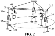
- Each universal joint 310 comprises a first part 311 secured to the nut, an intermediate part 312 mounted to rotate with respect to the first part around a respective first axis, one example of which is denoted XX on the figure 2 and 3 , and a third part 313 integral with the platform, and mounted for rotation with respect to the intermediate part around a respective second axis, perpendicular to the first, and an example of which is denoted YY on the picture 2 .
- the axes of rotation of the universal joint connection are advantageously perpendicular to the axis of the screw-nut connection. Blocking this rotation makes it possible to prevent rotation of the nut relative to the screw.
- the motor 33 driving the screw in rotation causes, by this locking in rotation of the nut, the translation of the second portion 32 with respect to the first 31.
- the platform in translation, by an identical and simultaneous translation of the three actuators 30, or to orient the platform, by individually controlling each actuator to obtain the desired orientation, as in the position represented. on the picture 1a .
- This variable orientation of the platform 20 is made possible by the gimbal links on the platform side and the pivot links on the support side.
- the screw-nut connection can be formed by a ball screw or by a roller screw. The fact of using this type of structure of screw-nut connections makes it possible to carry out only transmissions of movement by rotation and not by translation in the device. In fact, in space, sliding connections are not recommended because they present difficulties in controlling friction and play, as well as difficulties in confining the lubricant, which limit the service life of the mechanisms and reduce performance in terms of accuracy or stability.
- the screw-nut connections of the three linear actuators are formed by roller screws, which make it possible to obtain a finer pitch than ball screws, and therefore more precise control.
- the roller screw comprises the screw 35, comprising a barrel 350 and a threaded rod 351, a threaded nut 36 mounted on the threaded rod, the threaded nut 36 comprising a plurality of rollers 360 distributed around the screw.
- the roller screw is lubricated, typically with grease or oil.
- the device 1 since the device 1 is to be used in space, it is necessary to avoid the vaporization of the lubricant, so that the lubrication is maintained throughout the lifetime of the device, and also to avoid possible contamination of other devices or instruments located in the vicinity of it.
- the roller screw comprises a sheath 37 extending around the screw 35 and the nut 36, and which comprises several portions arranged relative to each other to limit the escape of vaporized molecules of lubricant while by allowing the relative movement of the second portion of the actuator with respect to the first.
- the actuators are arranged, relative to the support 10 and to the platform 20, so that the support 10 and the platform 20 are each symmetrical according to a central symmetry, in order to facilitate the control of the actuators.
- the actuators are arranged so that their bases, that is to say the end of the second portion 32 located at the level of the pivot connection 320, are evenly distributed over a circle passing through the axis of each actuator, the axis of the pivot connection 320 of each actuator preferably being tangent to the circle.
- each universal joint 310 connected to the platform are preferably evenly distributed over a circle, the axes of rotation of each part 313 with respect to the intermediate part 312 of the Universal joint being radial with respect to the circle.
- the actuators 30 are therefore suitable for moving the platform 20 relative to the support.
- the actuators 30 are arranged to move the platform 20 from and to a stacked position, shown in the figure 1b , in which the platform 20 bears against the support 10.
- the support is shaped to allow the support of the platform against the latter when the platform is in the stacked position. It may in particular comprise, as represented in the example of the figure 1 , support feet 11 projecting from the wall of the spacecraft on which the device 1 is mounted.
- the support 10 is shaped to have three support points, typically formed by three projecting support feet 11, the three support points being respectively adjacent to each linear actuator 30. Support points are sized to support the weight of the platform and the equipment mounted on it.
- the support 10 and the platform 20 are shaped to be able to block the three degrees of freedom of the platform in the stacked position.
- the support 10 and the platform 20 are shaped to establish, in the stacked position, three connections of the sphere-chute or sphere-V type 40, represented on the figure 5 .
- a connection of the sphere-duct type 40 is a connection obtained by the contact of a sphere or an element having a locally spherical outline 41, formed for example by a surface of the platform 20 or an element attached thereto, on a trough 42, formed for example in a foot 11 of the support, and which forms two point contacts.
- a sphere-chute connection allows a translation along an axis of the chute, and a rotation along three axes, it thus blocks a translation along two axes perpendicular to those of the chute.
- the axes of the sphere-chute connections are therefore not parallel.
- the three sphere-chute connections being regularly distributed along a circle, for example a circle passing through the centers of the spheres 41, the axes of the connections can be radial with respect to this circle.
- This triple connection forms an embedded connection making it possible to immobilize the platform with respect to the support.
- the fact of having recourse to three connections of the sphere-chute type makes it possible to achieve this result by using identical mechanical connections, which makes the device industrially simpler and less expensive to manufacture.
- the deployment and pointing device advantageously comprises a launch holding device adapted to apply a pre-load on the platform 20 towards the support 10, when the platform is in the stacked position at launch, to hold the platform shape pressed against the support despite the efforts and vibrations induced by the launch.
- the launch support device may comprise one or more fuse wires initially maintaining the platform resting against the support, the wire being burned once the device is in orbit, to release the platform.
- the embedding connection formed between the platform and the support creates degrees of hyperstatism at the level of the overall device.
- the support points between the support and the platform are positioned as close as possible to the linear actuators.
- each Cardan-type link 310 between a linear actuator and the platform can comprise flexible strips 314 intended to reduce the forces that can be transmitted at this link, and in particular the forces in the axis of the actuator.
- the threaded screw 35 of the screw-nut connection 34 of each actuator 30 can also be dimensioned to reduce the forces that it can transmit, and in particular the forces transverse to the axis of the actuator, by presenting a sufficiently high length to diameter ratio, which must be determined on a case-by-case basis by the person skilled in the art according to the mass of the pointed equipment, the forces acceptable by the screw, etc. It is nevertheless understood that the flexibilities induced must however be limited in order to maintain good positioning precision of the platform in orbit, this precision having a direct impact on the positioning precision of the equipment mounted on the platform and, in in the case of an optical instrument, on its sharpness.
- the deployment and pointing device 1 therefore makes it possible, thanks to the mechanism described above, both to orient equipment precisely and according to control methods which can be simplified by a symmetry of the device and the identical nature of the actuators, but also to return the platform and the equipment to a stacked position where launch support can be ensured. As a result, resistance to the forces generated by the launch is ensured without the need to oversize the actuators or the joints or to preload them, which would increase the mass and the cost of the equipment.
- the device is therefore initially mounted in the stacked position, the mobile platform being held in abutment against the support by means of a launch holding device. Once launched, the platform is released and the linear actuators can be controlled to first move the platform away from the support by means of a translation, for example perpendicular to the plane of the support, then to orient the platform. -shape and therefore the equipment in at least one predetermined direction.
- the device may comprise an electronic control card integrating a computer and a memory storing instructions necessary for controlling the actuators to execute a series of predefined movements.
- the device can comprise a remote communication interface making it possible to receive control instructions transmitted from a ground station.
Landscapes
- Engineering & Computer Science (AREA)
- Remote Sensing (AREA)
- General Engineering & Computer Science (AREA)
- Aviation & Aerospace Engineering (AREA)
- Mechanical Engineering (AREA)
- Physics & Mathematics (AREA)
- Astronomy & Astrophysics (AREA)
- General Physics & Mathematics (AREA)
- Transmission Devices (AREA)
Description
La présente demande concerne un dispositif de déploiement et de pointage d'un équipement, le dispositif étant solidaire d'un engin spatial tel qu'un satellite ou une sonde spatiale. La demande s'applique par exemple au déploiement et au pointage d'instruments optiques tels que des télescopes.The present application relates to a device for deploying and pointing equipment, the device being integral with a spacecraft such as a satellite or a space probe. The application applies for example to the deployment and aiming of optical instruments such as telescopes.
Dans des missions spatiales, on souhaite pouvoir orienter un équipement embarqué sur un engin spatial de manière à le placer en condition de fonctionnement. Par exemple, pour des missions d'observation, on veut permettre à un instrument optique de pointer une cible depuis un engin spatial, que la cible soit sur Terre ou dans l'espace. On peut également avoir besoin d'orienter d'autres types d'équipements tels que des antennes, des réflecteurs, des propulseurs, etc. Pour cela, il est nécessaire d'utiliser un mécanisme de pointage permettant au moins deux degrés de liberté en rotation.In space missions, it is desired to be able to orient equipment on board a spacecraft so as to place it in operating condition. For example, for observation missions, we want to allow an optical instrument to point to a target from a spacecraft, whether the target is on Earth or in space. One may also need to orient other types of equipment such as antennas, reflectors, thrusters, etc. For this, it is necessary to use a pointing mechanism allowing at least two degrees of freedom in rotation.
Notamment, il est connu de monter l'équipement sur un support orientable. Dans ce cas, il peut être avantageux que le support mobile présente un troisième degré de liberté en translation, pour permettre d'une part de ramener l'équipement dans une position se trouvant en dehors du domaine de déplacement opérationnel, afin de le gerber au lancement, mais d'autre part pour permettre plus de liberté sur les mouvements de l'équipement. Sur le plan de la cinématique, un troisième degré de liberté peut permettre de fournir à l'équipement une trajectoire lui évitant des chocs vis-à-vis d'autres composants de l'engin spatial. Sur le plan de la dynamique, un troisième degré de liberté peut permettre de déplacer le centre de rotation de l'équipement et de mieux maîtriser les problématiques d'inertie vue par les actionneurs.In particular, it is known to mount the equipment on an adjustable support. In this case, it may be advantageous for the mobile support to have a third degree of freedom in translation, to allow on the one hand to bring the equipment into a position lying outside the field of operational movement, in order to stack it at the launch, but on the other hand to allow more freedom on the movements of the equipment. In terms of kinematics, a third degree of freedom can make it possible to provide the equipment with a trajectory preventing it from colliding with other components of the spacecraft. In terms of dynamics, a third degree of freedom can make it possible to move the center of rotation of the equipment and better control the problems of inertia seen by the actuators.
Ainsi, on connaît du document
Tous les actionneurs sont formés d'un mandrin relié à un élément linéaire assemblé à la plate-forme, et l'ajustement de la position de la plate-forme est réalisé en ajustant pour chaque actionneur la longueur de l'élément linéaire, en le déroulant ou en l'enroulant sur le mandrin correspondant.All the actuators are formed by a mandrel connected to a linear element assembled to the platform, and the adjustment of the position of the platform is achieved by adjusting for each actuator the length of the linear element, by unrolling or winding it on the corresponding mandrel.
Ce dispositif présente cependant plusieurs inconvénients liés à la structure des actionneurs. En premier lieu, les éléments linéaires, du fait de leur géométrie, ne peuvent pas présenter une rigidité suffisante pour permettre le déploiement et l'orientation de charges lourdes ou d'instruments massifs. De plus, même en concevant des éléments linéaires rigides, il est alors difficile de les enrouler sur des mandrins et il faut utiliser des mandrins présentant un rayon relativement élevé, ce qui augmente l'encombrement du dispositif et diminue sa précision. Le document
Il existe donc un besoin pour améliorer la situation.There is therefore a need to improve the situation.
Compte-tenu de ce qui précède, l'invention a pour but de proposer un dispositif de déploiement et de pointage d'un équipement pouvant présenter une masse plus élevée, et permettant une précision accrue par rapport à l'art antérieur.In view of the foregoing, the object of the invention is to propose a device for deploying and pointing equipment that can have a higher mass, and allowing increased precision compared to the prior art.
Un autre but de l'invention est de proposer un dispositif présentant une bonne tenue aux efforts générés lors du lancement de l'engin spatial portant le dispositif et l'équipement.Another object of the invention is to propose a device exhibiting good resistance to the forces generated during the launch of the spacecraft carrying the device and the equipment.
A cet égard, la présente demande a pour objet un dispositif de déploiement et de pointage d'un équipement, comprenant :
- une plate-forme mobile de réception de l'équipement,
- un support solidaire d'une paroi d'un engin spatial, et
- trois actionneurs linéaires identiques reliant le support à la plate-forme mobile, les actionneurs étant adaptés pour déplacer la plate-forme mobile en translation selon un axe et pour orienter la plate-forme mobile en rotation autour de deux axes,
- une première portion reliée à la plate-forme mobile par une liaison Cardan,
- une deuxième portion reliée au support par une liaison pivot,
- un moteur, et
- une liaison vis-écrou reliant entre elles la première et la deuxième portion,
- a mobile platform for receiving the equipment,
- a support secured to a wall of a spacecraft, and
- three identical linear actuators connecting the support to the mobile platform, the actuators being adapted to move the mobile platform in translation along an axis and to orient the mobile platform in rotation around two axes,
- a first portion connected to the mobile platform by a universal joint,
- a second portion connected to the support by a pivot connection,
- a motor, and
- a screw-nut connection connecting the first and the second portion together,
Avantageusement, mais facultativement, le dispositif de déploiement et de pointage comprend en outre au moins l'une des caractéristiques suivantes.Advantageously, but optionally, the deployment and pointing device further comprises at least one of the following characteristics.
Dans un mode de réalisation, les actionneurs linéaires sont adaptés pour déplacer la plate-forme mobile de réception de l'équipement entre une position gerbée et au moins une position opérationnelle, et le support et la plate-forme mobile sont conformés pour qu'en position gerbée, la plate-forme mobile soit en appui contre le support par trois points d'appui adjacents respectivement à chaque actionneur linéaire.In one embodiment, the linear actuators are adapted to move the mobile platform for receiving the equipment between a stacked position and at least one operational position, and the support and the mobile platform are shaped so that in stacked position, the mobile platform is supported against the support by three support points adjacent respectively to each linear actuator.
Dans un mode de réalisation, la plate-forme mobile et le support sont conformés pour établir, en position gerbée, trois liaisons de type sphère-goulotte entre la plate-forme mobile et le support, les axes des liaisons sphère-goulotte étant non parallèles entre eux.In one embodiment, the mobile platform and the support are shaped to establish, in the stacked position, three sphere-chute type connections between the mobile platform and the support, the axes of the sphere-chute connections being non-parallel between them.
Dans un mode de réalisation, les trois liaisons sphère-goulotte sont équi-réparties sur un cercle, les axes des goulottes s'étendant radialement par rapport au cercle.In one embodiment, the three sphere-chute connections are evenly distributed over a circle, the axes of the chutes extending radially with respect to the circle.
Dans un mode de réalisation, le dispositif de déploiement et de pointage comprend en outre un dispositif de maintien au lancement adapté pour maintenir, en position gerbée, la plate-forme mobile en appui contre le support lors du lancement de l'engin spatial.In one embodiment, the deployment and pointing device further comprises a launch holding device adapted to hold, in the stacked position, the mobile platform resting against the support during the launch of the spacecraft.
Dans un mode de réalisation, le dispositif de déploiement et de pointage est en outre dimensionné pour permettre, en position gerbée, une transmission d'efforts plus importants par les points d'appui que par les actionneurs linéaires.In one embodiment, the deployment and pointing device is also dimensioned to allow, in the stacked position, a transmission of greater forces by the support points than by the linear actuators.
Dans un mode de réalisation, chaque liaison Cardan comprend au moins une lame flexible adaptée pour limiter les efforts pouvant être transmis de la plate-forme à l'actionneur linéaire correspondant.In one embodiment, each Cardan link comprises at least one flexible blade adapted to limit the forces that can be transmitted from the platform to the corresponding linear actuator.
Dans un mode de réalisation, les actionneurs sont disposés relativement au support et à la plate-forme de réception de sorte que chacun du support et de la plate-forme sont symétriques selon une symétrie centrale.In one embodiment, the actuators are disposed relative to the support and the receiving platform such that each of the support and the platform are symmetrical according to a central symmetry.
Dans un mode de réalisation, chaque liaison vis-écrou est formée par une vis à rouleaux. La vis à rouleaux peut alors comprendre une vis, comprenant un fût et une tige filetée, un écrou fileté monté sur la tige filetée, et un fourreau s'étendant autour de la vis et de l'écrou, et logeant un lubrifiant, le fourreau comprenant :
- une première portion de fourreau reliée à l'écrou et couvrant l'extrémité libre de la tige filetée de la vis, ladite première portion de fourreau étant fermée à une extrémité située à l'extrémité libre de la tige filetée,
- une deuxième portion fixe de fourreau couvrant le fût de la vis,
- une troisième portion de fourreau montée coulissante sur la deuxième portion, et
- une quatrième portion de fourreau reliée à l'écrou, et s'étendant depuis l'écrou vers le fût de la vis de manière à recouvrir en partie la troisième portion,
- a first portion of sheath connected to the nut and covering the free end of the threaded rod of the screw, said first portion of sheath being closed at one end located at the free end of the threaded rod,
- a second fixed portion of sheath covering the shaft of the screw,
- a third sheath portion slidably mounted on the second portion, and
- a fourth portion of sheath connected to the nut, and extending from the nut towards the barrel of the screw so as to partially cover the third portion,
Un autre objet concerne un procédé de déploiement d'un dispositif selon la description qui précède, le dispositif étant monté sur un satellite, et se trouvant initialement en position gerbée dans laquelle la plate-forme mobile est en appui contre le support,
le procédé comprenant la commande de chaque actionneur linéaire pour écarter par translation la plate-forme mobile du support, et la commande de chaque actionneur pour orienter la plate-forme selon au moins une direction prédéterminée.Another object relates to a method for deploying a device according to the preceding description, the device being mounted on a satellite, and being initially in a stacked position in which the mobile platform is resting against the support,
the method comprising controlling each linear actuator to translate the movable platform away from the support, and controlling each actuator to orient the platform in at least one predetermined direction.
Un autre objet concerne un produit programme d'ordinateur, comprenant des instructions de code pour la mise en oeuvre du procédé selon la description qui précède, lorsqu'il est mis en œuvre par un calculateur.Another object relates to a computer program product, comprising code instructions for implementing the method according to the preceding description, when it is implemented by a computer.
Le dispositif proposé permet d'atteindre les objectifs énoncés ci-avant au moyen d'actionneurs linéaires comprenant une liaison vis-écrou et deux portions reliées respectivement à une plate-forme de réception de l'instrument à pointer et à un support de l'engin spatial. La liaison vis-écrou permet d'obtenir une très bonne précision pour le positionnement et le pointage de l'équipement du fait du fort rapport de réduction que l'on peut obtenir entre la rotation du moteur et la translation de l'actionneur.The device proposed makes it possible to achieve the objectives stated above by means of linear actuators comprising a screw-nut connection and two portions connected respectively to a platform for receiving the instrument to be pointed and to a support for the spacecraft. The screw-nut connection makes it possible to obtain very good precision for the positioning and aiming of the equipment due to the high reduction ratio that can be obtained between the rotation of the motor and the translation of the actuator.
Le dispositif présente également une bonne tenue au lancement puisqu'il permet de ramener la plate-forme de réception de l'instrument à pointer dans une position gerbée, dans laquelle, pour chaque actionneur, un point d'appui supplémentaire et voisin de l'actionneur est établi entre la plate-forme et le support, permettant une transmission des efforts entre la plate-forme et le support par ce point d'appui et non par l'actionneur. Des souplesses sont également introduites dans les actionneurs pour assurer que les efforts liés au lancement passent par les points d'appui supplémentaires et non par les actionneurs.The device also has good launch resistance since it makes it possible to bring the receiving platform of the instrument to be pointed into a stacked position, in which, for each actuator, an additional support point and close to the actuator is established between the platform and the support, allowing a transmission of forces between the platform and the support by this point of support and not by the actuator. Flexibilities are also introduced in the actuators to ensure that the forces linked to the launch pass through the additional support points and not through the actuators.
D'autres caractéristiques, détails et avantages apparaîtront à la lecture de la description détaillée ci-après, et à l'analyse des dessins annexés, sur lesquels :
-
Fig. 1a
[Fig. 1a ] représente un dispositif de déploiement et de pointage selon un mode de réalisation, dans une configuration opérationnelle. -
Fig. 1b
[Fig. 1b ] représente un dispositif de déploiement et de pointage selon un mode de réalisation, dans une configuration gerbée. -
Fig. 2
[Fig. 2 ] est un schéma cinématique du dispositif de déploiement et de pointage selon un mode de réalisation. -
Fig. 3
[Fig. 3 ] représente un exemple de liaison vis-écrou d'un actionneur linéaire du dispositif de déploiement et de pointage. -
Fig. 4
[Fig. 4 ] représente un exemple de liaison Cardan utilisée dans un dispositif de déploiement et de pointage selon un mode de réalisation. -
Fig. 5
[Fig. 5 ] représente un exemple de réalisation d'une liaison sphère-V utilisée dans un dispositif de déploiement et de pointage selon un mode de réalisation. -
Fig. 6a
[Fig. 6a ] représente un exemple de vis à rouleau utilisé dans un dispositif de déploiement et de pointage selon un mode de réalisation. -
Fig. 6b
[Fig. 6b ] est une vue agrandie de la vis à rouleau représentée enfigure 6a .
-
Fig. 1a
[Fig. 1a ] shows a deployment and pointing device according to one embodiment, in an operational configuration. -
Fig. 1b
[Fig. 1b ] shows a deployment and pointing device according to one embodiment, in a stacked configuration. -
Fig. 2
[Fig. 2 ] is a kinematic diagram of the deployment and pointing device according to one embodiment. -
Fig. 3
[Fig. 3 ] shows an example of a screw-nut connection of a linear actuator of the deployment and pointing device. -
Fig. 4
[Fig. 4 ] represents an example of a Cardan link used in a deployment and pointing device according to one embodiment. -
Fig. 5
[Fig. 5 ] shows an exemplary embodiment of a sphere-V link used in a deployment and pointing device according to one embodiment. -
Fig. 6a
[Fig. 6a ] shows an example of a roller screw used in a deployment and aiming device according to one embodiment. -
Fig. 6b
[Fig. 6b ] is an enlarged view of the roller screw shown infigure 6a .
En référence aux
Le dispositif 1 est adapté pour être monté de façon fixe à un engin spatial (non représenté) tel qu'un satellite. Il comprend à cet égard un support 10 solidaire d'une paroi de l'engin spatial. Dans un mode de réalisation, le support 10 du dispositif 1 peut même être intégré à une paroi de l'engin spatial, c'est-à-dire être une partie d'une paroi de l'engin spatial.Device 1 is adapted to be fixedly mounted to a spacecraft (not shown) such as a satellite. It comprises in this respect a
Le dispositif 1 comprend également une plate-forme 20 de réception de l'instrument, sur laquelle l'équipement est monté fixe. Cette plate-forme 20 est mobile par rapport à l'engin spatial, et par rapport au support 10, selon trois degrés de libertés, comprenant un degré de translation et deux degrés de rotation, selon des axes de rotation de préférence perpendiculaires à la direction de translation. Par exemple, la direction de translation peut être perpendiculaire au plan du support 10, et les axes de rotation peuvent être perpendiculaires entre eux.The device 1 also comprises a
Pour mettre en mouvement la plate-forme 20 selon ces degrés de libertés, le dispositif 1 comprend trois actionneurs 30 identiques, reliant le support 10 à la plate-forme 20. Le fait que les actionneurs soient identiques rend la conception et la fabrication plus aisées donc moins coûteuse, et facilite également le contrôle de la position de la plate-forme.To set the
Chaque actionneur 30 est linéaire, c'est-à-dire qu'il est adapté pour générer un mouvement de translation.Each
Plus précisément, et en référence aux
une première portion 31 reliée à la plate-forme 20par une liaison 310 Cardan, c'est-à-dire une liaison selon deux axes de rotation sensiblement perpendiculaires entre eux.- une deuxième
portion 32reliée au support 10 par uneliaison pivot 320, - un moteur 33, et
- une liaison de type vis-
écrou 34, reliant entre elles la premièreportion 31 et la deuxièmeportion 32.
- a
first portion 31 connected to theplatform 20 by auniversal joint 310, that is to say a connection along two axes of rotation substantially perpendicular to each other. - a
second portion 32 connected to thesupport 10 by apivot connection 320, - a
motor 33, and - a screw-
nut type connection 34, connecting together thefirst portion 31 and thesecond portion 32.
La liaison vis-écrou 34 comprend une vis filetée 35 et un écrou fileté 36 monté sur la vis. La première portion 31 de chaque actionneur est solidaire de l'écrou fileté 36, et la deuxième portion 32 est solidaire de la vis 35.The screw-
De plus, la liaison Cardan 310 est adaptée pour interdire une rotation de la première portion 31 dans l'axe de l'actionneur linéaire 30, c'est-à-dire dans l'axe de la liaison vis-écrou. Chaque liaison Cardan 310 comprend une première pièce 311 solidaire de l'écrou, une pièce intermédiaire 312 montée à rotation par rapport à la première pièce autour d'un premier axe respectif dont un exemple et noté X-X sur les
Il est donc possible de commander la plate-forme en translation, par une translation identique et simultanée des trois actionneurs 30, ou d'orienter la plate-forme, en commandant individuellement chaque actionneur pour obtenir l'orientation voulue, comme sur la position représentée sur la
Dans un mode de réalisation avantageux, les liaisons vis-écrou des trois actionneurs linéaires sont formées par des vis à rouleaux, qui permettent d'obtenir un pas plus fin que des vis à billes, et donc un contrôle plus précis.In an advantageous embodiment, the screw-nut connections of the three linear actuators are formed by roller screws, which make it possible to obtain a finer pitch than ball screws, and therefore more precise control.
Dans ce cas, en référence aux
Ainsi, dans un mode de réalisation, le fourreau 37 comprend :
une première portion 370, reliée à l'écrou et couvrant l'extrémité libre de la tige filetée 351 de la vis, cette première portion étant fermée à une extrémité située du côté de l'extrémité libre de la tige filetée,- une deuxième
portion 371 fixe, couvrant le fût 350 de la vis, - une troisième
portion 372 montée coulissante sur la deuxième portion, et - une quatrième
portion 373 reliée à l'écrou, en s'étendant depuis l'écrou vers le fût de la vis de manière à recouvrir en partie la troisième portion, et
- a
first portion 370, connected to the nut and covering the free end of the threadedrod 351 of the screw, this first portion being closed at one end located on the side of the free end of the threaded rod, - a second fixed
portion 371, covering theshaft 350 of the screw, - a
third portion 372 slidably mounted on the second portion, and - a
fourth portion 373 connected to the nut, extending from the nut towards the barrel of the screw so as to partially cover the third portion, and
De retour aux
Par exemple, du côté du support 10, les actionneurs sont disposés de sorte que leurs bases, c'est-à-dire l'extrémité de la deuxième portion 32 située au niveau de la liaison pivot 320, soient équi-réparties sur un cercle passant par l'axe de chaque actionneur, l'axe de la liaison pivot 320 de chaque actionneur étant de préférence tangent au cercle.For example, on the side of the
Du côté de la plate-forme 20, les pièces 313 de chaque liaison Cardan 310 liée à la plate-forme sont de préférence équi-réparties sur un cercle, les axes de rotation de chaque pièce 313 par rapport à la pièce intermédiaire 312 de la liaison Cardan étant radiales par rapport au cercle.On the side of the
Les actionneurs 30 sont donc adaptés pour déplacer la plate-forme 20 relativement au support. En particulier, les actionneurs 30 sont agencés pour déplacer la plate-forme 20 depuis et vers une position gerbée, représentée sur la
De plus le support 10 et la plate-forme 20 sont conformés pour pouvoir bloquer les trois degrés de liberté de la plate-forme en position gerbée. Selon un mode de réalisation, le support 10 et la plate-forme 20 sont conformés pour établir, en position gerbée, trois liaisons de type sphère-goulotte ou sphère-V 40, représentées sur la
Le dispositif de déploiement et de pointage comporte avantageusement un dispositif de maintien au lancement adapté pour appliquer une pré-charge sur la plate-forme 20 vers le support 10, lorsque la plate-forme est en position gerbée au lancement, pour maintenir la plate-forme plaquée contre le support malgré les efforts et les vibrations induits par le lancement. Par exemple, selon une conception connue de l'Homme du Métier, le dispositif de maintien au lancement peut comprendre un ou plusieurs fils fusibles maintenant initialement la plate-forme en appui contre le support, le fil étant brûlé une fois le dispositif en orbite, pour libérer la plate-forme.The deployment and pointing device advantageously comprises a launch holding device adapted to apply a pre-load on the
Par ailleurs, la liaison encastrement formée entre la plate-forme et le support vient créer des degrés d'hyperstatisme au niveau du dispositif global. Pour limiter au maximum les contraintes induites par cet hyperstatisme, les points d'appui entre le support et la plate-forme sont positionnés le plus près possible des actionneurs linéaires.Furthermore, the embedding connection formed between the platform and the support creates degrees of hyperstatism at the level of the overall device. To minimize the stresses induced by this hyperstatism, the support points between the support and the platform are positioned as close as possible to the linear actuators.
De plus, l'ensemble du dispositif est dimensionné pour permettre qu'en position gerbée, les efforts, et notamment les efforts induits lors du lancement, transitent par les points d'appui plutôt que par les actionneurs linéaires 30, ou en d'autres termes, que les efforts transitant par les points d'appui lors du lancement soient plus importants que ceux transitant par les actionneurs. A cet égard, les points d'appui sont dimensionnés pour pouvoir tenir ces efforts. Par ailleurs, les actionneurs linéaires sont adaptés pour réduire les efforts qu'ils peuvent transmettre, en y insérant des éléments souples. En référence à la
Le dispositif 1 de déploiement et de pointage permet donc, grâce au mécanisme décrit ci-avant, à la fois d'orienter un équipement de façon précise et selon des procédés de commande qui peuvent être simplifiés par une symétrie du dispositif et le caractère identique des actionneurs, mais également de ramener la plate-forme et l'équipement dans une position gerbée où le maintien au lancement peut être assuré. De ce fait, la tenue aux efforts générés par le lancement est assurée sans avoir besoin de surdimensionner les actionneurs ou les articulations ou de les précharger, ce qui augmenterait la masse et le coût de l'équipement.The deployment and pointing device 1 therefore makes it possible, thanks to the mechanism described above, both to orient equipment precisely and according to control methods which can be simplified by a symmetry of the device and the identical nature of the actuators, but also to return the platform and the equipment to a stacked position where launch support can be ensured. As a result, resistance to the forces generated by the launch is ensured without the need to oversize the actuators or the joints or to preload them, which would increase the mass and the cost of the equipment.
Dans un mode de réalisation, le dispositif est donc monté initialement en position gerbée, la plate-forme mobile étant maintenue en appui contre le support au moyen d'un dispositif de maintien au lancement. Une fois le lancement effectué, la plate-forme est libérée et les actionneurs linéaires peuvent être commandés pour d'abord écarter la plate-forme du support au moyen d'une translation, par exemple perpendiculaire au plan du support, puis pour orienter la plate-forme et donc l'équipement selon au moins une direction prédéterminée.In one embodiment, the device is therefore initially mounted in the stacked position, the mobile platform being held in abutment against the support by means of a launch holding device. Once launched, the platform is released and the linear actuators can be controlled to first move the platform away from the support by means of a translation, for example perpendicular to the plane of the support, then to orient the platform. -shape and therefore the equipment in at least one predetermined direction.
Le dispositif peut comprendre une carte électronique de commande intégrant un calculateur et une mémoire stockant des instructions nécessaires à la commande des actionneurs pour exécuter une série de mouvements prédéfinie. En variante, le dispositif peut comprendre une interface de communication à distance permettant de recevoir des instructions de commande émise depuis une station au sol.The device may comprise an electronic control card integrating a computer and a memory storing instructions necessary for controlling the actuators to execute a series of predefined movements. As a variant, the device can comprise a remote communication interface making it possible to receive control instructions transmitted from a ground station.
Liste des références :
- 1 : dispositif de déploiement et de pointage
- 10 : support
- 11 : pieds d'appui
- 20 : plate-forme mobile
- 30 : actionneur linéaire
- 31 : première portion de l'actionneur
- 310 liaison Cardan
- 311 pièce de la liaison solidaire de l'écrou
- 312 : pièce intermédiaire de la liaison
- 313 : pièce de la liaison solidaire de la plate-forme
- 314 : lames flexibles
- 32 : deuxième portion de l'actionneur
- 320 : liaison pivot
- 33 : moteur
- 34 : liaison vis-écrou
- 35 : vis filetée
- 350 : fût
- 351 : tige filetée
- 36 : écrou fileté
- 360 : rouleaux
- 37 : fourreau
- 370 : première portion de fourreau
- 371 : deuxième portion de fourreau
- 372 : troisième portion de fourreau
- 373 : quatrième portion de fourreau
- 374 : rebord périphérique de la troisième portion
- 375 : rebord périphérique de la quatrième portion
- 376 : ressort
- 40 : liaison sphère-goulotte
- 41 : surface sphérique
- 42 : goulotte
- X-X : axe de rotation entre première et deuxième pièce d'une liaison Cardan
- Y-Y : axe de rotation entre deuxième et troisième pièce d'une liaison Cardan
- 1: deployment and pointing device
- 10: medium
- 11: support feet
- 20: mobile platform
- 30: linear actuator
- 31: first portion of the actuator
- 310 universal joint
- 311 part of the integral connection of the nut
- 312: intermediate part of the connection
- 313: part of the solid connection of the platform
- 314: flexible blades
- 32: second portion of the actuator
- 320: pivot link
- 33: motor
- 34: screw-nut connection
- 35: threaded screw
- 350: cask
- 351: threaded rod
- 36: threaded nut
- 360: rolls
- 37: scabbard
- 370: first portion of scabbard
- 371: second portion of scabbard
- 372: third portion of scabbard
- 373: fourth portion of scabbard
- 374: peripheral edge of the third portion
- 375: peripheral edge of the fourth portion
- 376: spring
- 40: sphere-duct connection
- 41: spherical surface
- 42: chute
- XX: axis of rotation between first and second part of a universal joint
- YY: axis of rotation between second and third part of a universal joint
Claims (12)
- Device (1) for deploying and pointing an item of equipment, comprising:- a mobile platform (20) for receiving the equipment,- a support (10) attached to a wall of a spacecraft, and- three identical linear actuators (30) connecting the support to the mobile platform, the actuators (30) being adapted to move the mobile platform in translation along an axis and to orient the mobile platform in rotation about two axes,characterised in that each linear actuator (30) comprises:- a first portion (31) connected to the mobile platform (20) by a cardan joint (310),- a second portion (32) connected to the support by a pivot connection (320),- a motor (33), and- a screw-nut connection (34) interconnecting the first (31) and second portion (32),the cardan joint (310) of each actuator being adapted to prevent a rotation in the axis of the screw-nut connection (34) such that the rotational actuation of the screw or nut by the motor brings about a translation between the first (31) and second portion (32).
- Device according to claim 1, wherein the linear actuators (30) are adapted to move the mobile platform (20) for receiving the equipment between a closed position and at least one operational position, and the support (10) and mobile platform (20) are designed so that in a closed position, the mobile platform bears against the support via three support points adjacent respectively to each linear actuator.
- Device according to the preceding claim, wherein the mobile platform (20) and the support (10) are designed to establish, in a closed position, three sphere-chute type connections (40) between the mobile platform (20) and the support (10), the axes of the sphere-chute connections (40) being non-parallel to each other.
- Device according to the preceding claim, wherein the sphere-chute connections (40) are equally spaced on a circle, the axes of the chutes (42) extending radially with respect of the circle.
- Device according to one of claims 2 to 4, further comprising a launch holding device adapted to hold, in a closed position, the mobile platform against the support during the launch of the spacecraft.
- Device according to one of claims 2 to 5, the device (1) further being sized to allow, in a closed position, greater forces to be transmitted via the support points than via the linear actuators (30).
- Device (1) according to the preceding claim, wherein each cardan joint (310) comprises at least one flexible blade (314) adapted to limit the forces that can be transmitted from the platform (20) to the corresponding linear actuator.
- Device according to one of the preceding claims, wherein the actuators (30) are arranged relative to the support (10) and to the receiving platform (20) such that each of the support (10) and platform (20) are symmetrical according to a central symmetry.
- Device according to one of the preceding claims, wherein each screw-nut connection (34) is formed by a roller screw.
- Device according to the preceding claim, wherein the roller screw comprises a screw (35), comprising a shank (350) and a threaded rod (351), a threaded nut (36) mounted on the threaded rod, and a sleeve (37) extending around the screw (35) and nut (36), and housing a lubricant, the sleeve comprising:- a first sleeve portion (370) connected to the nut (36) and covering the free end of the threaded rod of the screw, said first sleeve portion being closed to an end situated at the free end of the threaded rod,- a second fixed sleeve portion (371) covering the shank of the screw,- a third sleeve portion (372) slidably mounted on the second portion (371), and- a fourth sleeve portion (373) connected to the nut, and extending from the nut (36) towards the shank of the screw so as to partially cover the third portion (372),wherein the third (372) and fourth (373) sleeve portions are designed to prevent the lubricant escaping from the sleeve.
- Method for deploying a device (1) according to one of the preceding claims mounted on a satellite, the device being initially in a closed position in which the mobile platform (20) bears against the support (10),
the method comprising controlling of each linear actuator (30) to move the mobile platform away from the support by translation, and controlling each actuator to orient the platform according to at least one predetermined direction. - Computer program product, comprising code instructions for implementing the method according to the preceding claim, when it is implemented by a computer.
Applications Claiming Priority (2)
| Application Number | Priority Date | Filing Date | Title |
|---|---|---|---|
| FR2004989A FR3110550B1 (en) | 2020-05-19 | 2020-05-19 | Device for deploying and pointing equipment carried by a spacecraft |
| PCT/FR2021/050813 WO2021234246A1 (en) | 2020-05-19 | 2021-05-11 | Device for deploying and pointing an item of equipment carried by a spacecraft |
Publications (2)
| Publication Number | Publication Date |
|---|---|
| EP3947158A1 EP3947158A1 (en) | 2022-02-09 |
| EP3947158B1 true EP3947158B1 (en) | 2022-04-27 |
Family
ID=72560700
Family Applications (1)
| Application Number | Title | Priority Date | Filing Date |
|---|---|---|---|
| EP21731248.7A Active EP3947158B1 (en) | 2020-05-19 | 2021-05-11 | Device for deploying and pointing an item of equipment carried by a spacecraft |
Country Status (6)
| Country | Link |
|---|---|
| US (1) | US11834202B2 (en) |
| EP (1) | EP3947158B1 (en) |
| AU (1) | AU2021276587B2 (en) |
| ES (1) | ES2914598T3 (en) |
| FR (1) | FR3110550B1 (en) |
| WO (1) | WO2021234246A1 (en) |
Families Citing this family (2)
| Publication number | Priority date | Publication date | Assignee | Title |
|---|---|---|---|---|
| CN114084210B (en) * | 2021-12-02 | 2023-05-30 | 中国船舶工业系统工程研究院 | Three-dimensional mobile operation platform and unmanned aerial vehicle carrying bracket applied to same |
| CN117508660A (en) * | 2023-10-24 | 2024-02-06 | 哈尔滨工业大学 | Gear drive type plate-shaped load repeated locking and releasing device based on mechanical arm assistance |
Family Cites Families (8)
| Publication number | Priority date | Publication date | Assignee | Title |
|---|---|---|---|---|
| FR2672836B1 (en) * | 1991-02-15 | 1995-06-02 | Onera (Off Nat Aerospatiale) | JOINT DEVICE WITH PARALLEL STRUCTURE AND APPARATUS FOR TRANSMITTING REMOTE MOTION USING THE SAME. |
| KR100334902B1 (en) * | 1999-12-06 | 2002-05-04 | 윤덕용 | 6 Degree-of-freedom Parallel Mechanism for Micro-positioning Task |
| FR2989229B1 (en) * | 2012-04-06 | 2015-03-06 | Thales Sa | RECONFIGURABLE ANTENNA REFLECTOR IN SERVICE |
| US9694455B2 (en) * | 2012-12-05 | 2017-07-04 | Alio Industries, Inc. | Precision tripod motion system with six degrees of freedom |
| WO2015168799A1 (en) * | 2014-05-08 | 2015-11-12 | UNIVERSITé LAVAL | Parallel mechanism with kinematically redundant actuation |
| FR3048418B1 (en) | 2016-03-02 | 2019-04-19 | Thales | DEVICE FOR DEPLOYING AND POINTING |
| EP3249632A1 (en) * | 2016-05-26 | 2017-11-29 | E2M Technologies B.V. | A movement platform system |
| FR3079281B1 (en) * | 2018-03-22 | 2020-03-20 | Thales | POSITIONING DEVICE |
-
2020
- 2020-05-19 FR FR2004989A patent/FR3110550B1/en active Active
-
2021
- 2021-05-11 AU AU2021276587A patent/AU2021276587B2/en active Active
- 2021-05-11 WO PCT/FR2021/050813 patent/WO2021234246A1/en unknown
- 2021-05-11 ES ES21731248T patent/ES2914598T3/en active Active
- 2021-05-11 US US17/926,044 patent/US11834202B2/en active Active
- 2021-05-11 EP EP21731248.7A patent/EP3947158B1/en active Active
Also Published As
| Publication number | Publication date |
|---|---|
| ES2914598T3 (en) | 2022-06-14 |
| EP3947158A1 (en) | 2022-02-09 |
| WO2021234246A1 (en) | 2021-11-25 |
| US20230182926A1 (en) | 2023-06-15 |
| US11834202B2 (en) | 2023-12-05 |
| FR3110550B1 (en) | 2022-05-20 |
| AU2021276587B2 (en) | 2023-01-05 |
| AU2021276587A1 (en) | 2022-12-15 |
| FR3110550A1 (en) | 2021-11-26 |
Similar Documents
| Publication | Publication Date | Title |
|---|---|---|
| EP3947158B1 (en) | Device for deploying and pointing an item of equipment carried by a spacecraft | |
| FR3047813B1 (en) | METHOD FOR CONTROLLING SATELLITE ATTITUDE GUIDANCE, SATELLITE, SATELLITE PLURALITIES AND ASSOCIATED COMPUTER PROGRAM | |
| EP2468629B1 (en) | Large extendable rigid structures | |
| EP3174794B1 (en) | Satellite comprising an optical photography instrument | |
| WO1996039328A1 (en) | Tilting adapter device for carrying a plurality of payloads on a single launch vehicle | |
| EP3962816B1 (en) | Device for damping docking to a satellite | |
| EP2256039A1 (en) | Through-pivot with flexible elements and spacecraft comprising such a pivot | |
| EP1964778B1 (en) | Pivot with blades | |
| EP3213999B1 (en) | Deployment and pointing device | |
| EP3045396B1 (en) | Pointing assembly of an instrument | |
| FR2669972A1 (en) | DEVICE FOR TEMPORARILY ASSURING AN OBJECT TO A MONOBLOCK RESTRAINT HOLDER. | |
| FR2780774A1 (en) | PASSIVE SELF-PROTECTION DEVICE FOR MOBILE MACHINE SUCH AS A HELICOPTER | |
| EP3135971B1 (en) | Improved system for braking a valve | |
| EP3089913A1 (en) | Segmented structure, in particular for a satellite antenna reflector, provided with at least one rotational and translational deployment device | |
| EP1635485B1 (en) | Optical transmission method between an on-board spacecraft terminal and a distant terminal, and spacecraft adapted for said method | |
| EP1170616A1 (en) | Mounting device for an ocular holding arm in a rotorcraft-like aircraft | |
| EP2927992B1 (en) | Mechanical holding system for holding a battery in a tube-shaped compartment | |
| WO2002084361A1 (en) | Device for mounting and correcting the position of a mirror extending in the shadow of the mirror and optical system fitted with said device | |
| EP0455543B1 (en) | Device for pointing a reflector antenna | |
| EP3877799B1 (en) | Dual axis optical pointing device | |
| WO2021170931A1 (en) | Radiator with reduced insolation and improved guidance system for geostationary satellite | |
| FR3131281A1 (en) | SYSTEM FOR BALANCING THE CENTER OF INERTIA OF A TELECOMMUNICATIONS SATELLITE. | |
| WO2021122137A1 (en) | Device for orienting a load in two orthogonal axes of rotation |
Legal Events
| Date | Code | Title | Description |
|---|---|---|---|
| STAA | Information on the status of an ep patent application or granted ep patent |
Free format text: STATUS: UNKNOWN |
|
| STAA | Information on the status of an ep patent application or granted ep patent |
Free format text: STATUS: THE INTERNATIONAL PUBLICATION HAS BEEN MADE |
|
| PUAI | Public reference made under article 153(3) epc to a published international application that has entered the european phase |
Free format text: ORIGINAL CODE: 0009012 |
|
| STAA | Information on the status of an ep patent application or granted ep patent |
Free format text: STATUS: REQUEST FOR EXAMINATION WAS MADE |
|
| GRAP | Despatch of communication of intention to grant a patent |
Free format text: ORIGINAL CODE: EPIDOSNIGR1 |
|
| STAA | Information on the status of an ep patent application or granted ep patent |
Free format text: STATUS: GRANT OF PATENT IS INTENDED |
|
| 17P | Request for examination filed |
Effective date: 20211027 |
|
| AK | Designated contracting states |
Kind code of ref document: A1 Designated state(s): AL AT BE BG CH CY CZ DE DK EE ES FI FR GB GR HR HU IE IS IT LI LT LU LV MC MK MT NL NO PL PT RO RS SE SI SK SM TR |
|
| INTG | Intention to grant announced |
Effective date: 20220117 |
|
| GRAS | Grant fee paid |
Free format text: ORIGINAL CODE: EPIDOSNIGR3 |
|
| GRAA | (expected) grant |
Free format text: ORIGINAL CODE: 0009210 |
|
| STAA | Information on the status of an ep patent application or granted ep patent |
Free format text: STATUS: THE PATENT HAS BEEN GRANTED |
|
| AK | Designated contracting states |
Kind code of ref document: B1 Designated state(s): AL AT BE BG CH CY CZ DE DK EE ES FI FR GB GR HR HU IE IS IT LI LT LU LV MC MK MT NL NO PL PT RO RS SE SI SK SM TR |
|
| DAV | Request for validation of the european patent (deleted) | ||
| DAX | Request for extension of the european patent (deleted) | ||
| REG | Reference to a national code |
Ref country code: GB Ref legal event code: FG4D Free format text: NOT ENGLISH |
|
| REG | Reference to a national code |
Ref country code: CH Ref legal event code: EP |
|
| REG | Reference to a national code |
Ref country code: AT Ref legal event code: REF Ref document number: 1486790 Country of ref document: AT Kind code of ref document: T Effective date: 20220515 |
|
| REG | Reference to a national code |
Ref country code: DE Ref legal event code: R096 Ref document number: 602021000078 Country of ref document: DE |
|
| REG | Reference to a national code |
Ref country code: IE Ref legal event code: FG4D Free format text: LANGUAGE OF EP DOCUMENT: FRENCH |
|
| REG | Reference to a national code |
Ref country code: ES Ref legal event code: FG2A Ref document number: 2914598 Country of ref document: ES Kind code of ref document: T3 Effective date: 20220614 |
|
| REG | Reference to a national code |
Ref country code: NL Ref legal event code: FP |
|
| REG | Reference to a national code |
Ref country code: LT Ref legal event code: MG9D |
|
| REG | Reference to a national code |
Ref country code: AT Ref legal event code: MK05 Ref document number: 1486790 Country of ref document: AT Kind code of ref document: T Effective date: 20220427 |
|
| PG25 | Lapsed in a contracting state [announced via postgrant information from national office to epo] |
Ref country code: SE Free format text: LAPSE BECAUSE OF FAILURE TO SUBMIT A TRANSLATION OF THE DESCRIPTION OR TO PAY THE FEE WITHIN THE PRESCRIBED TIME-LIMIT Effective date: 20220427 Ref country code: PT Free format text: LAPSE BECAUSE OF FAILURE TO SUBMIT A TRANSLATION OF THE DESCRIPTION OR TO PAY THE FEE WITHIN THE PRESCRIBED TIME-LIMIT Effective date: 20220829 Ref country code: NO Free format text: LAPSE BECAUSE OF FAILURE TO SUBMIT A TRANSLATION OF THE DESCRIPTION OR TO PAY THE FEE WITHIN THE PRESCRIBED TIME-LIMIT Effective date: 20220727 Ref country code: LT Free format text: LAPSE BECAUSE OF FAILURE TO SUBMIT A TRANSLATION OF THE DESCRIPTION OR TO PAY THE FEE WITHIN THE PRESCRIBED TIME-LIMIT Effective date: 20220427 Ref country code: HR Free format text: LAPSE BECAUSE OF FAILURE TO SUBMIT A TRANSLATION OF THE DESCRIPTION OR TO PAY THE FEE WITHIN THE PRESCRIBED TIME-LIMIT Effective date: 20220427 Ref country code: GR Free format text: LAPSE BECAUSE OF FAILURE TO SUBMIT A TRANSLATION OF THE DESCRIPTION OR TO PAY THE FEE WITHIN THE PRESCRIBED TIME-LIMIT Effective date: 20220728 Ref country code: FI Free format text: LAPSE BECAUSE OF FAILURE TO SUBMIT A TRANSLATION OF THE DESCRIPTION OR TO PAY THE FEE WITHIN THE PRESCRIBED TIME-LIMIT Effective date: 20220427 Ref country code: BG Free format text: LAPSE BECAUSE OF FAILURE TO SUBMIT A TRANSLATION OF THE DESCRIPTION OR TO PAY THE FEE WITHIN THE PRESCRIBED TIME-LIMIT Effective date: 20220727 Ref country code: AT Free format text: LAPSE BECAUSE OF FAILURE TO SUBMIT A TRANSLATION OF THE DESCRIPTION OR TO PAY THE FEE WITHIN THE PRESCRIBED TIME-LIMIT Effective date: 20220427 |
|
| PG25 | Lapsed in a contracting state [announced via postgrant information from national office to epo] |
Ref country code: RS Free format text: LAPSE BECAUSE OF FAILURE TO SUBMIT A TRANSLATION OF THE DESCRIPTION OR TO PAY THE FEE WITHIN THE PRESCRIBED TIME-LIMIT Effective date: 20220427 Ref country code: PL Free format text: LAPSE BECAUSE OF FAILURE TO SUBMIT A TRANSLATION OF THE DESCRIPTION OR TO PAY THE FEE WITHIN THE PRESCRIBED TIME-LIMIT Effective date: 20220427 Ref country code: LV Free format text: LAPSE BECAUSE OF FAILURE TO SUBMIT A TRANSLATION OF THE DESCRIPTION OR TO PAY THE FEE WITHIN THE PRESCRIBED TIME-LIMIT Effective date: 20220427 Ref country code: IS Free format text: LAPSE BECAUSE OF FAILURE TO SUBMIT A TRANSLATION OF THE DESCRIPTION OR TO PAY THE FEE WITHIN THE PRESCRIBED TIME-LIMIT Effective date: 20220827 |
|
| REG | Reference to a national code |
Ref country code: DE Ref legal event code: R097 Ref document number: 602021000078 Country of ref document: DE |
|
| PG25 | Lapsed in a contracting state [announced via postgrant information from national office to epo] |
Ref country code: SM Free format text: LAPSE BECAUSE OF FAILURE TO SUBMIT A TRANSLATION OF THE DESCRIPTION OR TO PAY THE FEE WITHIN THE PRESCRIBED TIME-LIMIT Effective date: 20220427 Ref country code: SK Free format text: LAPSE BECAUSE OF FAILURE TO SUBMIT A TRANSLATION OF THE DESCRIPTION OR TO PAY THE FEE WITHIN THE PRESCRIBED TIME-LIMIT Effective date: 20220427 Ref country code: RO Free format text: LAPSE BECAUSE OF FAILURE TO SUBMIT A TRANSLATION OF THE DESCRIPTION OR TO PAY THE FEE WITHIN THE PRESCRIBED TIME-LIMIT Effective date: 20220427 Ref country code: MC Free format text: LAPSE BECAUSE OF FAILURE TO SUBMIT A TRANSLATION OF THE DESCRIPTION OR TO PAY THE FEE WITHIN THE PRESCRIBED TIME-LIMIT Effective date: 20220427 Ref country code: EE Free format text: LAPSE BECAUSE OF FAILURE TO SUBMIT A TRANSLATION OF THE DESCRIPTION OR TO PAY THE FEE WITHIN THE PRESCRIBED TIME-LIMIT Effective date: 20220427 Ref country code: DK Free format text: LAPSE BECAUSE OF FAILURE TO SUBMIT A TRANSLATION OF THE DESCRIPTION OR TO PAY THE FEE WITHIN THE PRESCRIBED TIME-LIMIT Effective date: 20220427 Ref country code: CZ Free format text: LAPSE BECAUSE OF FAILURE TO SUBMIT A TRANSLATION OF THE DESCRIPTION OR TO PAY THE FEE WITHIN THE PRESCRIBED TIME-LIMIT Effective date: 20220427 |
|
| PLBE | No opposition filed within time limit |
Free format text: ORIGINAL CODE: 0009261 |
|
| STAA | Information on the status of an ep patent application or granted ep patent |
Free format text: STATUS: NO OPPOSITION FILED WITHIN TIME LIMIT |
|
| PG25 | Lapsed in a contracting state [announced via postgrant information from national office to epo] |
Ref country code: AL Free format text: LAPSE BECAUSE OF FAILURE TO SUBMIT A TRANSLATION OF THE DESCRIPTION OR TO PAY THE FEE WITHIN THE PRESCRIBED TIME-LIMIT Effective date: 20220427 |
|
| 26N | No opposition filed |
Effective date: 20230130 |
|
| REG | Reference to a national code |
Ref country code: BE Ref legal event code: MM Effective date: 20230531 |
|
| PG25 | Lapsed in a contracting state [announced via postgrant information from national office to epo] |
Ref country code: LU Free format text: LAPSE BECAUSE OF NON-PAYMENT OF DUE FEES Effective date: 20230511 |
|
| REG | Reference to a national code |
Ref country code: IE Ref legal event code: MM4A |
|
| PG25 | Lapsed in a contracting state [announced via postgrant information from national office to epo] |
Ref country code: IE Free format text: LAPSE BECAUSE OF NON-PAYMENT OF DUE FEES Effective date: 20230511 |
|
| PG25 | Lapsed in a contracting state [announced via postgrant information from national office to epo] |
Ref country code: IE Free format text: LAPSE BECAUSE OF NON-PAYMENT OF DUE FEES Effective date: 20230511 |
|
| PG25 | Lapsed in a contracting state [announced via postgrant information from national office to epo] |
Ref country code: HU Free format text: LAPSE BECAUSE OF FAILURE TO SUBMIT A TRANSLATION OF THE DESCRIPTION OR TO PAY THE FEE WITHIN THE PRESCRIBED TIME-LIMIT; INVALID AB INITIO Effective date: 20210511 Ref country code: BE Free format text: LAPSE BECAUSE OF NON-PAYMENT OF DUE FEES Effective date: 20230531 |
|
| PGFP | Annual fee paid to national office [announced via postgrant information from national office to epo] |
Ref country code: NL Payment date: 20240521 Year of fee payment: 4 |
|
| PGFP | Annual fee paid to national office [announced via postgrant information from national office to epo] |
Ref country code: DE Payment date: 20240521 Year of fee payment: 4 |
|
| PGFP | Annual fee paid to national office [announced via postgrant information from national office to epo] |
Ref country code: CH Payment date: 20240602 Year of fee payment: 4 |
|
| PGFP | Annual fee paid to national office [announced via postgrant information from national office to epo] |
Ref country code: ES Payment date: 20240627 Year of fee payment: 4 |
|
| PGFP | Annual fee paid to national office [announced via postgrant information from national office to epo] |
Ref country code: IT Payment date: 20240531 Year of fee payment: 4 Ref country code: FR Payment date: 20240527 Year of fee payment: 4 |