EP3946801B1 - Method for the fusion welding of one or more steel sheets of press-hardenable steel - Google Patents
Method for the fusion welding of one or more steel sheets of press-hardenable steel Download PDFInfo
- Publication number
- EP3946801B1 EP3946801B1 EP20717637.1A EP20717637A EP3946801B1 EP 3946801 B1 EP3946801 B1 EP 3946801B1 EP 20717637 A EP20717637 A EP 20717637A EP 3946801 B1 EP3946801 B1 EP 3946801B1
- Authority
- EP
- European Patent Office
- Prior art keywords
- focal spot
- laser focal
- welding
- laser
- steel
- Prior art date
- Legal status (The legal status is an assumption and is not a legal conclusion. Google has not performed a legal analysis and makes no representation as to the accuracy of the status listed.)
- Active
Links
- 238000003466 welding Methods 0.000 title claims description 106
- 229910000831 Steel Inorganic materials 0.000 title claims description 96
- 239000010959 steel Substances 0.000 title claims description 96
- 238000000034 method Methods 0.000 title claims description 86
- 230000004927 fusion Effects 0.000 title claims description 15
- 239000000463 material Substances 0.000 claims description 63
- 239000000945 filler Substances 0.000 claims description 59
- 238000000576 coating method Methods 0.000 claims description 36
- 239000011248 coating agent Substances 0.000 claims description 35
- 229910052782 aluminium Inorganic materials 0.000 claims description 32
- XAGFODPZIPBFFR-UHFFFAOYSA-N aluminium Chemical compound [Al] XAGFODPZIPBFFR-UHFFFAOYSA-N 0.000 claims description 28
- 238000009826 distribution Methods 0.000 claims description 23
- 239000011651 chromium Substances 0.000 claims description 15
- 230000003287 optical effect Effects 0.000 claims description 15
- PALQHNLJJQMCIQ-UHFFFAOYSA-N boron;manganese Chemical compound [Mn]#B PALQHNLJJQMCIQ-UHFFFAOYSA-N 0.000 claims description 14
- PXHVJJICTQNCMI-UHFFFAOYSA-N Nickel Chemical compound [Ni] PXHVJJICTQNCMI-UHFFFAOYSA-N 0.000 claims description 13
- 229910000712 Boron steel Inorganic materials 0.000 claims description 12
- 229910052804 chromium Inorganic materials 0.000 claims description 12
- 239000012535 impurity Substances 0.000 claims description 11
- 210000001503 joint Anatomy 0.000 claims description 11
- 239000000203 mixture Substances 0.000 claims description 11
- 230000001681 protective effect Effects 0.000 claims description 11
- 229910052799 carbon Inorganic materials 0.000 claims description 10
- 229910052748 manganese Inorganic materials 0.000 claims description 10
- 229910052750 molybdenum Inorganic materials 0.000 claims description 9
- 238000005275 alloying Methods 0.000 claims description 8
- 229910052759 nickel Inorganic materials 0.000 claims description 8
- 239000000843 powder Substances 0.000 claims description 8
- 229910052710 silicon Inorganic materials 0.000 claims description 8
- OKTJSMMVPCPJKN-UHFFFAOYSA-N Carbon Chemical compound [C] OKTJSMMVPCPJKN-UHFFFAOYSA-N 0.000 claims description 5
- 238000010438 heat treatment Methods 0.000 claims description 5
- VYZAMTAEIAYCRO-UHFFFAOYSA-N Chromium Chemical compound [Cr] VYZAMTAEIAYCRO-UHFFFAOYSA-N 0.000 claims description 4
- 230000010355 oscillation Effects 0.000 claims description 4
- 229910052698 phosphorus Inorganic materials 0.000 claims description 4
- 230000001154 acute effect Effects 0.000 claims description 3
- 229910052796 boron Inorganic materials 0.000 claims description 3
- 230000008569 process Effects 0.000 description 23
- 229910052751 metal Inorganic materials 0.000 description 22
- 239000002184 metal Substances 0.000 description 22
- 239000007789 gas Substances 0.000 description 15
- 239000000155 melt Substances 0.000 description 11
- XEEYBQQBJWHFJM-UHFFFAOYSA-N Iron Chemical compound [Fe] XEEYBQQBJWHFJM-UHFFFAOYSA-N 0.000 description 10
- 239000011572 manganese Substances 0.000 description 10
- XKRFYHLGVUSROY-UHFFFAOYSA-N Argon Chemical compound [Ar] XKRFYHLGVUSROY-UHFFFAOYSA-N 0.000 description 8
- CURLTUGMZLYLDI-UHFFFAOYSA-N Carbon dioxide Chemical compound O=C=O CURLTUGMZLYLDI-UHFFFAOYSA-N 0.000 description 6
- 230000000694 effects Effects 0.000 description 6
- 238000001816 cooling Methods 0.000 description 5
- 238000002156 mixing Methods 0.000 description 5
- 229910018125 Al-Si Inorganic materials 0.000 description 4
- 229910018520 Al—Si Inorganic materials 0.000 description 4
- IJGRMHOSHXDMSA-UHFFFAOYSA-N Atomic nitrogen Chemical compound N#N IJGRMHOSHXDMSA-UHFFFAOYSA-N 0.000 description 4
- 229910052786 argon Inorganic materials 0.000 description 4
- 230000015572 biosynthetic process Effects 0.000 description 4
- 238000005265 energy consumption Methods 0.000 description 4
- 239000002245 particle Substances 0.000 description 4
- 230000008901 benefit Effects 0.000 description 3
- 229910002092 carbon dioxide Inorganic materials 0.000 description 3
- 229910052734 helium Inorganic materials 0.000 description 3
- 239000001307 helium Substances 0.000 description 3
- SWQJXJOGLNCZEY-UHFFFAOYSA-N helium atom Chemical compound [He] SWQJXJOGLNCZEY-UHFFFAOYSA-N 0.000 description 3
- 238000000265 homogenisation Methods 0.000 description 3
- 229910052742 iron Inorganic materials 0.000 description 3
- 238000004519 manufacturing process Methods 0.000 description 3
- 230000009467 reduction Effects 0.000 description 3
- 239000000126 substance Substances 0.000 description 3
- 238000012360 testing method Methods 0.000 description 3
- CSDREXVUYHZDNP-UHFFFAOYSA-N alumanylidynesilicon Chemical compound [Al].[Si] CSDREXVUYHZDNP-UHFFFAOYSA-N 0.000 description 2
- 229910001566 austenite Inorganic materials 0.000 description 2
- 230000008859 change Effects 0.000 description 2
- 238000010276 construction Methods 0.000 description 2
- 238000013461 design Methods 0.000 description 2
- 238000010891 electric arc Methods 0.000 description 2
- 239000000835 fiber Substances 0.000 description 2
- WPBNNNQJVZRUHP-UHFFFAOYSA-L manganese(2+);methyl n-[[2-(methoxycarbonylcarbamothioylamino)phenyl]carbamothioyl]carbamate;n-[2-(sulfidocarbothioylamino)ethyl]carbamodithioate Chemical compound [Mn+2].[S-]C(=S)NCCNC([S-])=S.COC(=O)NC(=S)NC1=CC=CC=C1NC(=S)NC(=O)OC WPBNNNQJVZRUHP-UHFFFAOYSA-L 0.000 description 2
- 229910000734 martensite Inorganic materials 0.000 description 2
- 238000002844 melting Methods 0.000 description 2
- 230000008018 melting Effects 0.000 description 2
- 229910052757 nitrogen Inorganic materials 0.000 description 2
- 239000013307 optical fiber Substances 0.000 description 2
- 230000035515 penetration Effects 0.000 description 2
- 238000005240 physical vapour deposition Methods 0.000 description 2
- 230000009466 transformation Effects 0.000 description 2
- 229910000760 Hardened steel Inorganic materials 0.000 description 1
- PWHULOQIROXLJO-UHFFFAOYSA-N Manganese Chemical compound [Mn] PWHULOQIROXLJO-UHFFFAOYSA-N 0.000 description 1
- ZOKXTWBITQBERF-UHFFFAOYSA-N Molybdenum Chemical compound [Mo] ZOKXTWBITQBERF-UHFFFAOYSA-N 0.000 description 1
- XUIMIQQOPSSXEZ-UHFFFAOYSA-N Silicon Chemical compound [Si] XUIMIQQOPSSXEZ-UHFFFAOYSA-N 0.000 description 1
- HCHKCACWOHOZIP-UHFFFAOYSA-N Zinc Chemical compound [Zn] HCHKCACWOHOZIP-UHFFFAOYSA-N 0.000 description 1
- 229910045601 alloy Inorganic materials 0.000 description 1
- 239000000956 alloy Substances 0.000 description 1
- 230000009286 beneficial effect Effects 0.000 description 1
- 230000037396 body weight Effects 0.000 description 1
- 239000001569 carbon dioxide Substances 0.000 description 1
- 239000012159 carrier gas Substances 0.000 description 1
- 238000006243 chemical reaction Methods 0.000 description 1
- 239000002131 composite material Substances 0.000 description 1
- 229910052802 copper Inorganic materials 0.000 description 1
- 239000010949 copper Substances 0.000 description 1
- 230000001419 dependent effect Effects 0.000 description 1
- 238000003618 dip coating Methods 0.000 description 1
- 238000005516 engineering process Methods 0.000 description 1
- 238000002474 experimental method Methods 0.000 description 1
- 230000002349 favourable effect Effects 0.000 description 1
- 239000001995 intermetallic alloy Substances 0.000 description 1
- 238000005304 joining Methods 0.000 description 1
- 238000000608 laser ablation Methods 0.000 description 1
- 239000010410 layer Substances 0.000 description 1
- 238000003754 machining Methods 0.000 description 1
- 238000012423 maintenance Methods 0.000 description 1
- 239000002923 metal particle Substances 0.000 description 1
- 239000011733 molybdenum Substances 0.000 description 1
- 238000010943 off-gassing Methods 0.000 description 1
- 230000003647 oxidation Effects 0.000 description 1
- 238000007254 oxidation reaction Methods 0.000 description 1
- 238000012805 post-processing Methods 0.000 description 1
- 230000002787 reinforcement Effects 0.000 description 1
- 239000011265 semifinished product Substances 0.000 description 1
- 238000007493 shaping process Methods 0.000 description 1
- 239000010703 silicon Substances 0.000 description 1
- 239000002344 surface layer Substances 0.000 description 1
- WFKWXMTUELFFGS-UHFFFAOYSA-N tungsten Chemical compound [W] WFKWXMTUELFFGS-UHFFFAOYSA-N 0.000 description 1
- 229910052721 tungsten Inorganic materials 0.000 description 1
- 239000010937 tungsten Substances 0.000 description 1
- 229910052725 zinc Inorganic materials 0.000 description 1
- 239000011701 zinc Substances 0.000 description 1
- 229910000859 α-Fe Inorganic materials 0.000 description 1
Images

Classifications
-
- B—PERFORMING OPERATIONS; TRANSPORTING
- B23—MACHINE TOOLS; METAL-WORKING NOT OTHERWISE PROVIDED FOR
- B23K—SOLDERING OR UNSOLDERING; WELDING; CLADDING OR PLATING BY SOLDERING OR WELDING; CUTTING BY APPLYING HEAT LOCALLY, e.g. FLAME CUTTING; WORKING BY LASER BEAM
- B23K26/00—Working by laser beam, e.g. welding, cutting or boring
- B23K26/02—Positioning or observing the workpiece, e.g. with respect to the point of impact; Aligning, aiming or focusing the laser beam
- B23K26/06—Shaping the laser beam, e.g. by masks or multi-focusing
- B23K26/064—Shaping the laser beam, e.g. by masks or multi-focusing by means of optical elements, e.g. lenses, mirrors or prisms
- B23K26/0648—Shaping the laser beam, e.g. by masks or multi-focusing by means of optical elements, e.g. lenses, mirrors or prisms comprising lenses
-
- B—PERFORMING OPERATIONS; TRANSPORTING
- B23—MACHINE TOOLS; METAL-WORKING NOT OTHERWISE PROVIDED FOR
- B23K—SOLDERING OR UNSOLDERING; WELDING; CLADDING OR PLATING BY SOLDERING OR WELDING; CUTTING BY APPLYING HEAT LOCALLY, e.g. FLAME CUTTING; WORKING BY LASER BEAM
- B23K26/00—Working by laser beam, e.g. welding, cutting or boring
- B23K26/02—Positioning or observing the workpiece, e.g. with respect to the point of impact; Aligning, aiming or focusing the laser beam
- B23K26/06—Shaping the laser beam, e.g. by masks or multi-focusing
- B23K26/0604—Shaping the laser beam, e.g. by masks or multi-focusing by a combination of beams
- B23K26/0608—Shaping the laser beam, e.g. by masks or multi-focusing by a combination of beams in the same heat affected zone [HAZ]
-
- B—PERFORMING OPERATIONS; TRANSPORTING
- B23—MACHINE TOOLS; METAL-WORKING NOT OTHERWISE PROVIDED FOR
- B23K—SOLDERING OR UNSOLDERING; WELDING; CLADDING OR PLATING BY SOLDERING OR WELDING; CUTTING BY APPLYING HEAT LOCALLY, e.g. FLAME CUTTING; WORKING BY LASER BEAM
- B23K26/00—Working by laser beam, e.g. welding, cutting or boring
- B23K26/02—Positioning or observing the workpiece, e.g. with respect to the point of impact; Aligning, aiming or focusing the laser beam
- B23K26/06—Shaping the laser beam, e.g. by masks or multi-focusing
- B23K26/073—Shaping the laser spot
- B23K26/0732—Shaping the laser spot into a rectangular shape
-
- B—PERFORMING OPERATIONS; TRANSPORTING
- B23—MACHINE TOOLS; METAL-WORKING NOT OTHERWISE PROVIDED FOR
- B23K—SOLDERING OR UNSOLDERING; WELDING; CLADDING OR PLATING BY SOLDERING OR WELDING; CUTTING BY APPLYING HEAT LOCALLY, e.g. FLAME CUTTING; WORKING BY LASER BEAM
- B23K26/00—Working by laser beam, e.g. welding, cutting or boring
- B23K26/02—Positioning or observing the workpiece, e.g. with respect to the point of impact; Aligning, aiming or focusing the laser beam
- B23K26/06—Shaping the laser beam, e.g. by masks or multi-focusing
- B23K26/073—Shaping the laser spot
- B23K26/0736—Shaping the laser spot into an oval shape, e.g. elliptic shape
-
- B—PERFORMING OPERATIONS; TRANSPORTING
- B23—MACHINE TOOLS; METAL-WORKING NOT OTHERWISE PROVIDED FOR
- B23K—SOLDERING OR UNSOLDERING; WELDING; CLADDING OR PLATING BY SOLDERING OR WELDING; CUTTING BY APPLYING HEAT LOCALLY, e.g. FLAME CUTTING; WORKING BY LASER BEAM
- B23K26/00—Working by laser beam, e.g. welding, cutting or boring
- B23K26/20—Bonding
- B23K26/21—Bonding by welding
- B23K26/24—Seam welding
- B23K26/242—Fillet welding, i.e. involving a weld of substantially triangular cross section joining two parts
-
- B—PERFORMING OPERATIONS; TRANSPORTING
- B23—MACHINE TOOLS; METAL-WORKING NOT OTHERWISE PROVIDED FOR
- B23K—SOLDERING OR UNSOLDERING; WELDING; CLADDING OR PLATING BY SOLDERING OR WELDING; CUTTING BY APPLYING HEAT LOCALLY, e.g. FLAME CUTTING; WORKING BY LASER BEAM
- B23K26/00—Working by laser beam, e.g. welding, cutting or boring
- B23K26/20—Bonding
- B23K26/21—Bonding by welding
- B23K26/24—Seam welding
- B23K26/26—Seam welding of rectilinear seams
-
- B—PERFORMING OPERATIONS; TRANSPORTING
- B23—MACHINE TOOLS; METAL-WORKING NOT OTHERWISE PROVIDED FOR
- B23K—SOLDERING OR UNSOLDERING; WELDING; CLADDING OR PLATING BY SOLDERING OR WELDING; CUTTING BY APPLYING HEAT LOCALLY, e.g. FLAME CUTTING; WORKING BY LASER BEAM
- B23K26/00—Working by laser beam, e.g. welding, cutting or boring
- B23K26/20—Bonding
- B23K26/32—Bonding taking account of the properties of the material involved
- B23K26/322—Bonding taking account of the properties of the material involved involving coated metal parts
-
- B—PERFORMING OPERATIONS; TRANSPORTING
- B23—MACHINE TOOLS; METAL-WORKING NOT OTHERWISE PROVIDED FOR
- B23K—SOLDERING OR UNSOLDERING; WELDING; CLADDING OR PLATING BY SOLDERING OR WELDING; CUTTING BY APPLYING HEAT LOCALLY, e.g. FLAME CUTTING; WORKING BY LASER BEAM
- B23K2101/00—Articles made by soldering, welding or cutting
- B23K2101/006—Vehicles
-
- B—PERFORMING OPERATIONS; TRANSPORTING
- B23—MACHINE TOOLS; METAL-WORKING NOT OTHERWISE PROVIDED FOR
- B23K—SOLDERING OR UNSOLDERING; WELDING; CLADDING OR PLATING BY SOLDERING OR WELDING; CUTTING BY APPLYING HEAT LOCALLY, e.g. FLAME CUTTING; WORKING BY LASER BEAM
- B23K2101/00—Articles made by soldering, welding or cutting
- B23K2101/18—Sheet panels
- B23K2101/185—Tailored blanks
-
- B—PERFORMING OPERATIONS; TRANSPORTING
- B23—MACHINE TOOLS; METAL-WORKING NOT OTHERWISE PROVIDED FOR
- B23K—SOLDERING OR UNSOLDERING; WELDING; CLADDING OR PLATING BY SOLDERING OR WELDING; CUTTING BY APPLYING HEAT LOCALLY, e.g. FLAME CUTTING; WORKING BY LASER BEAM
- B23K2101/00—Articles made by soldering, welding or cutting
- B23K2101/34—Coated articles, e.g. plated or painted; Surface treated articles
-
- B—PERFORMING OPERATIONS; TRANSPORTING
- B23—MACHINE TOOLS; METAL-WORKING NOT OTHERWISE PROVIDED FOR
- B23K—SOLDERING OR UNSOLDERING; WELDING; CLADDING OR PLATING BY SOLDERING OR WELDING; CUTTING BY APPLYING HEAT LOCALLY, e.g. FLAME CUTTING; WORKING BY LASER BEAM
- B23K2103/00—Materials to be soldered, welded or cut
- B23K2103/02—Iron or ferrous alloys
- B23K2103/04—Steel or steel alloys
-
- B—PERFORMING OPERATIONS; TRANSPORTING
- B23—MACHINE TOOLS; METAL-WORKING NOT OTHERWISE PROVIDED FOR
- B23K—SOLDERING OR UNSOLDERING; WELDING; CLADDING OR PLATING BY SOLDERING OR WELDING; CUTTING BY APPLYING HEAT LOCALLY, e.g. FLAME CUTTING; WORKING BY LASER BEAM
- B23K2103/00—Materials to be soldered, welded or cut
- B23K2103/08—Non-ferrous metals or alloys
- B23K2103/10—Aluminium or alloys thereof
Definitions
- the invention relates to a method for fusion welding one or more steel sheets made of press-hardenable steel, preferably manganese-boron steel, wherein the steel sheet or at least one of the steel sheets has a metallic coating made of aluminum, e.g. B. has an Al-Si coating, and wherein the fusion welding is carried out with the supply of additional material in the melt pool generated exclusively by means of at least one laser beam.
- Tailor-made blanks made of sheet steel are used in automobile construction to meet high crash safety requirements with the lowest possible body weight.
- tailored blanks individual blanks or strips of different material grades and/or sheet thicknesses are butt-joined together by laser welding.
- different points of a body component can be adapted to different loads.
- thicker or higher-strength sheet steel can be used in places subject to high loads, and thinner sheets or sheets of relatively soft deep-drawn grades can be used in the other places.
- Such tailor-made sheet metal blanks make additional reinforcement parts on the body superfluous. This saves material and makes it possible to reduce the overall weight of the body.
- manganese-boron steels In modern car body construction, sheets of manganese-boron steel are used, which achieve high strength during hot forming and rapid cooling.
- manganese-boron steels In the delivered condition, ie before hot forming, manganese-boron steels have a tensile strength of approx. 600 MPa and a ferritic-pearlitic structure.
- a completely martensitic structure can be set by press hardening, ie by heating to the austenitization temperature before forming and subsequent rapid cooling during or after forming Tensile strengths of up to 2000 MPa.
- Such components are often made from so-called tailor-welded blanks; This means that there is a connection between different sheet metal thicknesses and/or material grades that meet the requirements, usually by means of laser beam welding.
- the fusion welding of hot-formable, press-hardenable steel sheets is further limited by a surface coating of aluminum.
- a surface coating of aluminum e.g. B. an aluminum-silicon coating is usually provided to avoid scaling of the workpieces during hot forming.
- this surface coating has a very negative effect on the quality of welds. Because the fusion welding of the coated steel sheets not only melts the base material, but also the aluminum-containing surface coating and thus aluminum is introduced into the weld seam. If the aluminum content in the weld is between 2 and 10% by weight, ferritic areas (phases) form, which lead to a reduction in the strength of the weld. In such cases, the strength of the weld seam is lower than that of the base material, so that failure of the component concerned in the weld seam is to be expected, regardless of the combination of sheet thicknesses joined.
- the surface coating in the edge area of the sheet metal edges to be welded together is at least partially removed before the welding process using mechanical tools or laser ablation (cf. EP 2 007 545 B1 ).
- this partial removal of the surface coating requires an additional process step, which is both costly and time-consuming and thus impairs the economics of manufacturing components of the type described here.
- This hybrid welding process is intended to ensure that hot-formable blanks made of manganese-boron steel, which are provided with an Al-Si-based coating, can be welded in the area of the weld seam to be produced without removing the coating material beforehand, but this should still be ensured that aluminum on the abutting edges of the boards does not lead to a reduction in the tensile strength of the component in the weld seam.
- the weld pool is intended to be homogenized and local aluminum concentrations greater than 1.2% by weight, which produce a ferritic structure, are thereby eliminated.
- This known hybrid welding method is relatively expensive in terms of energy consumption due to the generation of the electric arc. Furthermore, the welding speed is comparatively low.
- a laser-arc hybrid welding The weld seam produced has an unfavorable seam shape for further forming, which may require post-processing.
- EP 2 919 942 B1 discloses a method for laser beam welding of sheets of press-hardenable manganese-boron steel in a butt joint using filler wire, the filler wire containing at least one alloying element from the group comprising manganese, chromium, molybdenum, silicon and/or nickel, which promotes the formation of austenite in the molten pool generated with the laser beam, and this at least one alloying element is present in the filler wire with a mass fraction that is at least 0.1% by weight greater than in the press-hardenable steel of the steel sheets.
- the filler wire has the following composition: 0.05 to 0.15% by weight C, 0.5 to 2.0% by weight Si, 1.0 to 2.5% by weight Mn, 0.5 to 2.0% by weight Cr + Mo, and 1.0 to 4.0% by weight Ni, balance iron and unavoidable impurities.
- the filler wire has a carbon mass fraction that is at least 0.1% by weight lower than the press-hardenable steel of the steel sheets.
- the method is also characterized in that the steel sheets used are uncoated or have been partially decoated before welding by removing their coating in the edge area along the abutting edges to be welded together.
- the EP 2 737 971 A1 describes a laser beam welding process for producing tailor-welded blanks from coated steel sheets using filler wire, the steel sheets being made of boron-alloyed steel and having an aluminum-silicon or zinc coating.
- the filler wire contains carbon or manganese, the mass fraction of this element in the filler wire being greater than in the base material of the coated steel sheets.
- the carbon content of the filler wire should be 0.1 to 0.8% by weight and its manganese content 1.5 to 7.0% by weight higher than that of the base material of the steel sheets. This is intended to avoid a reduction in the strength of the weld seam compared to the press-hardened steel sheets as a result of the penetration of coating material into the melt pool generated by the laser beam.
- the EP 2 736 672 B1 discloses a method for producing a component from coated steel sheets by laser beam welding using filler wire, the steel sheets having an aluminum-based coating which was removed in the edge areas along the abutting edges to be welded together to such an extent before welding that there was still an intermetallic alloy layer remains.
- the filler wire has the following composition: 0.6 to 1.5% by weight C, 1.0 to 4.0% by weight Mn, 0.1 to 0.6% by weight Si, max. 2 0.0% by weight Cr, and max. 0.2% by weight Ti, balance iron and impurities caused by machining.
- the DE 10 2017 120 051 A1 discloses a method for laser beam welding of steel sheets made of press-hardenable manganese-boron steel, in which at least one of the steel sheets has an aluminum coating.
- Laser beam welding is carried out by feeding filler wire into the molten bath that is produced exclusively by means of a laser beam, with the filler wire containing at least one alloying element that stabilizes austenite.
- the laser beam is made to oscillate in such a way that it oscillates transversely to the welding direction, with the oscillation frequency being at least 200 Hz.
- the process offers cost benefits, as it eliminates the need to remove the aluminum coating at the edge of the sheet metal edges to be welded. However, the oscillation of the laser beam reduces the achievable welding speed.
- DE 10 2014 001979 A1 represents the preamble of claim 1 and discloses a method for laser welding steel sheets with a surface coating of aluminum with the aid of a filler material.
- an attempt is made to compensate for a negative influence of the coating elements on the hardenability of the weld seam by adapting the filler material to the steel used.
- the present invention has for its object to provide a method of the type mentioned, with the steel sheets, of which at least one sheet is made of press-hardenable steel and has a metallic coating containing aluminum, can be joined in such a way that the weld seam after the Hot forming (press hardening) has a strength and hardness comparable to the base material, with the process being characterized by high productivity and a comparatively low energy consumption.
- a method of the type mentioned is to be specified, by which the hardenability of the weld seam is improved, regardless of whether the steel sheets to be welded together are steel sheets of the same or different material quality and/or steel sheets of different sheet thicknesses.
- the outlay in terms of plant technology for implementing the method should be relatively low.
- the aim is to create a method of the type mentioned at the outset with which sheets of press-hardenable steel that have an aluminum-based coating can be welded together economically and with which the hardenability of the weld seam is improved, so that the process window for an adequate curing process is increased. In particular, a high welding speed should be made possible.
- the invention provides that one or more optical elements are used to produce a single laser focal spot with different energy distribution on the melt pool in such a way that the laser focal spot has a smaller laser focal spot area and a larger laser focal spot area, with the larger laser focal spot area having a surface which is at least 2 times, preferably at least 3 times, an area irradiated by the smaller laser focal spot region, and a higher laser energy output per unit area is introduced into the smaller laser focal spot region than into the larger laser focal spot region.
- the described energy distribution according to the invention in the laser focal spot has the effect that the temperature distribution and thus the flows in the molten pool change compared to a temperature distribution and the flows in a melt pool generated with a conventional laser welding beam.
- the smaller laser focal spot area which can also be referred to as the main focal spot and in which a higher laser energy output per unit area is introduced than in the larger laser focal spot area (secondary focal spot), is essentially used for deep welding, while the larger laser focal spot area supports the welding process.
- the power of laser energy delivered through the smaller laser focal spot area may be at or about the same level as the power of laser energy delivered through the larger laser spot area. For example, a laser energy output of approx.
- the laser energy power introduced via the smaller laser focal spot area can have a significantly different level than the laser energy power introduced via the larger laser focal spot area.
- the energy introduced in the larger laser focal spot area is distributed over a larger area than the energy introduced in the smaller laser focal spot area.
- the effect of the energy introduced in the larger laser focal spot area (secondary focal spot) thus differs from the effect of the energy in the main focal spot.
- This different energy input or energy distribution makes it possible to achieve greater homogenization of the molten bath and thus a weld seam that is improved in terms of its hardenability. This increases the process window for an adequate curing process.
- the energy distribution is controlled such that the smaller laser focal spot area (main focal spot) produces a deep welding process, while the energy of the outer or larger laser focal spot area does not exceed the energy threshold area for deep welding.
- the threshold range is, for example, at a power density of approximately 1000 kW/cm 2 .
- the method according to the invention offers the particular advantage that a partial removal of the aluminum-containing surface coating in the edge region of the sheet metal edges to be welded to one another before the welding process is not necessary. Accordingly, a preferred embodiment of the method according to the invention provides that this is carried out essentially without prior removal, in particular without prior partial removal of the aluminum-containing surface coating from the edge region of the sheet metal edges to be welded to one another.
- the method according to the invention enables an optimized weld seam geometry, specifically a larger load-bearing sheet edge cross-section. This is particularly advantageous in the case of subsequent dynamic loads on the weld seam.
- a further advantage of the method according to the invention is the significantly reduced formation of welding spatter.
- the inventors see one reason for the reduced formation of weld spatter in the deliberately different energy distribution in the laser focal spot and the resulting special melt pool flow.
- the laser beam energy can be distributed largely variably in the laser focal spot.
- the different energy distribution or adapted energy input in the laser focal spot is achieved in the method according to the invention by means of one or more optical elements.
- this can be implemented via one or more diffractive or refractory optical elements and/or directly by using one or more appropriately arranged optical fibers.
- a correspondingly modified laser welding head can, for example, have two different diffractive or refractory optical elements, in particular lenses, which are axial and/or axial relative to one another can be moved radially.
- a correspondingly modified laser welding head can be implemented in a compact design.
- Another way to generate a different energy distribution in the individual laser focal spot is to split the laser beam and direct the resulting partial laser beams through different diffractive or refractory optical elements, in particular lenses, with the partial laser beams modulated in this way then being combined again into one laser beam and the The laser beam composed in this way is directed at the joint of the sheet steel edges to be welded together.
- Such a modified laser welding head can also be implemented in a compact design.
- Yet another way of generating a different energy distribution in the individual laser focal point is to combine two or more different laser beams, which are generated, for example, by means of similar or different laser light sources, in a laser beam optic in such a way that the resulting laser beam forms a single, composite laser focal point with a different power distribution generated.
- the device for guiding the laser welding head or the respective workpiece to be welded can be designed in a conventional manner in the above-specified embodiments of the invention, i.e. the method according to the invention does not require a more complex mechanical arrangement or more complex guiding device than is the case with conventional laser welding systems for carrying out a generic Process for fusion welding one or more steel sheets made of press-hardenable steel.
- a system for laser-arc hybrid welding, as z. B. from the U.S. 2008/0011720 A1 is known, however, requires a relatively complex mechanical one because of the longer effective range of the welding device Arrangement and guidance of the welding device or the workpiece to be welded, in particular when welding along a curved sheet metal edge contour.
- the method according to the invention is characterized by a low susceptibility to errors and high process stability.
- the method according to the invention enables high welding speeds with relatively low energy consumption, in particular in comparison to laser-arc hybrid welding.
- An advantageous embodiment of the invention is characterized in that the laser beam is operated essentially without oscillation during fusion welding.
- Substantially oscillation-free means that the laser beam is not set to oscillate intentionally. In this way, in particular, relatively high welding speeds can be achieved.
- the mounting of the laser welding head or the mounting of the optical elements in the laser welding head can thus be realized in a relatively simple manner.
- a further advantageous embodiment of the invention provides that the optical element or elements by means of which the laser focal spot with a different energy distribution is/are generated is/are designed in such a way that the position of the smaller laser focal spot area within the larger laser focal spot area can be adjusted relative to the latter is.
- the different energy input or different energy distribution in the laser focal spot can be optimally adapted to the respective welding conditions.
- the position of the smaller laser focal spot area is adjusted within the larger laser focal spot area in a direction parallel and/or transverse to the welding direction.
- the position of the smaller laser focal spot area is adjusted within the larger laser focal spot area so that the smaller laser focal spot area in the Substantially in the center of the larger laser focal spot area or in front of the center of the larger laser focal spot area as viewed in the direction of the welding direction.
- the shape of the larger laser focal spot area and/or the smaller laser focal spot area can be round, elliptical, square or rectangular, for example.
- a substantially round shape of the larger laser focal spot area and/or the smaller laser focal spot area can result in particular if, in the method according to the invention, the different energy distribution or adapted energy input in the laser focal spot is realized by means of one or more appropriately arranged optical fibers.
- the larger laser focal spot area has an elongated shape, in particular an oval, elliptical or rectangular shape, with a longitudinal axis of the larger laser focal spot area running essentially in the welding direction. This results in a relatively large weld pool area at the joint, so that at a certain welding speed there is more time available for outgassing of the weld pool until the weld seam solidifies.
- a further advantageous embodiment of the invention is characterized in that the larger laser focal spot area has a longitudinal extension that is at least twice, preferably at least 2.5 times, particularly preferably at least 3 times the average diameter or largest diameter of the smaller laser focal spot area amounts to. Tests by the inventors have shown that a very homogeneous distribution of aluminum that has flowed into the weld pool and remains in the weld seam can be achieved in this way.
- the fusion welding takes place with the supply of additional material (also called welding filler) into the melt pool that is produced exclusively by means of at least one laser beam.
- additional material also called welding filler
- the filler metal has several tasks.
- the ferrite-forming effect of aluminum flowing from the coating into the weld pool can be minimized by using suitable alloying elements in the filler metal, and thus the hardenability of the weld seam can be improved.
- the aluminum content of the weld seam is minimized by the addition of essentially aluminum-free additional material.
- Filler material is preferably fed into the weld pool in the form of a wire or powder. Additional material in the form of a wire can be fed into the weld pool in a very energy-efficient manner and with high quantity accuracy.
- powdered filler metal of a suitable particle size it is possible to mix the filler metal very evenly in the weld pool.
- the duration of the melting phase in laser welding is in a range from only about 6 ms to 125 ms. Since the welding time for laser welding is relatively short, a better mixing with the steel to be welded can be achieved with powdered filler metal than with the use of filler wire.
- the particles of the welding filler powder have, for example, a particle size in the range from 20 ⁇ m to 160 ⁇ m, preferably in the range from 20 ⁇ m to 160 ⁇ m.
- the powdered additional material is preferably supplied in the form of a gas-powder stream via at least one flow channel, with the gas-powder stream emerging from the flow channel being directed onto the molten bath and a Exit speed of at least 2 m/s, preferably at least 10 m/s, particularly preferably at least 15 m/s, so that there is a turbulent mixing of the filler metal with the molten pool, resulting in flow vortices in the molten pool. These flow vortices (turbulence) are caused in particular by the kinetics of the gas-powder flow.
- An upper limit of the exit speed of the gas-powder flow directed onto the molten bath can be, for example, 50 m/s, in particular 40 m/s or 30 m/s.
- the additional material fed to the molten bath when carrying out the method according to the invention is preferably essentially aluminum-free.
- an aluminum-free or essentially aluminum-free filler material is understood to mean a filler metal that contains no aluminum apart from unavoidable impurities or unavoidable trace amounts.
- the additional material contains at least one alloying element from a group comprising nickel, chromium and/or carbon.
- the filler material preferably contains 5 to 12% by weight Ni, 5 to 25% by weight Cr and 0.05 to 0.4% by weight C, optionally at least one other alloying element, remainder Iron and unavoidable impurities.
- a chromium content of the additional material in the range from 5 to 25% by weight is favorable in order to reduce the critical cooling rate of the weld seam and thus further improve the hardenability of the weld seam.
- a preferred embodiment of the method according to the invention is characterized in that the additional material used has the following composition: 0.05 to 0.4% by weight C, 0 to 2.0% by weight Si, 0 to 3.0% by weight -% Mn, 4 to 25 wt% Cr, 0 to 0.5 wt% Mo, and 5 to 12 wt% Ni, balance Fe and unavoidable impurities.
- a further advantageous embodiment of the method according to the invention is characterized in that the additional material, preferably in the form of a wire, is fed into the molten bath in such a way that the additional material is fed directly into the smaller laser focal spot area.
- the additional material preferably in the form of a wire, touches the smaller laser focal spot area or is essentially directed towards the smaller laser focal spot area. This ensures that the melted filler material flows around the vapor capillaries in the weld pool during deep penetration welding. This enables better mixing of the additional material with the material in the joint, d. H. Butt joint or lap joint of melted steel sheet material and thus a more homogeneous weld seam is achieved.
- a further advantageous embodiment of the method according to the invention is characterized in that the additional material, preferably in the form of a wire, is fed in slowly.
- a sluggish feed of additional material, in particular wire feed means that the additional material is fed ahead of the weld pool or the smaller laser focal spot area from the front, seen in the direction of welding.
- This configuration also allows for better mixing of the additional material with the material in the joint, d. H. Butt joint or lap joint of melted steel sheet material and thus a more homogeneous weld seam is achieved.
- a further advantageous embodiment of the method according to the invention is characterized in that the additional material supplied in the form of a wire is supplied to the molten bath in such a way that the central axis of the wire forms an acute angle of less than 50°, preferably less than 45°, particularly preferably less than 30°, in particular between 10° and includes 30°. This allows the additional material to be optimally fed into the deep welding area, in particular in the direction of the steam capillaries.
- the additional material preferably in the form of a wire, is heated to a temperature of at least 60° C., preferably at least 100° C., preferably at least 150° C. in particular heated to at least 180°.
- a significantly higher welding speed is possible compared to using an unheated filler wire. Because the tip of the heated filler wire can be melted faster with the laser beam.
- the welding process becomes more stable.
- the upper limit of the temperature of the preheated wire is below the temperature at which the wire loses its dimensional stability or is too low for reliable wire feeding.
- the upper limit of wire preheating is in the range of about 250°C to 300°C.
- a manganese-boron steel is preferably used as the press-hardenable steel.
- the steel sheet to be welded or at least one of the steel sheets to be welded together is selected such that it has a press-hardenable steel with the following composition: 0.10 to 0.50% by weight C, max. 0.40 wt% Si, 0.50 to 2.0 wt% Mn, max 0.025 wt% P, max 0.010 wt% S, max 0.60 wt% Cr, max 0.50 wt% Mo, max 0.050 wt% Ti, 0.0008 to 0.0070 wt% B, and min 0.010 wt% Al, balance Fe and unavoidable impurities.
- the components made from such a sheet steel have a high strength after press hardening.
- Sheets of different or identical manganese-boron steels can be welded to one another using the method according to the invention in order to provide tailor-made sheet metal semi-finished products that have maximum strength through press hardening.
- the method according to the invention can be used not only when joining several steel blanks of the same or different sheet thicknesses in a butt joint, of which at least one blank is made of press-hardenable steel and provided with a coating containing aluminum, but also when laser beam welding a single plate or strip-shaped steel sheet press-hardenable steel, preferably manganese-boron steel, which has a coating containing aluminum, in which case the sheet metal edges to be welded together are moved towards one another by forming, for example by folding or roll forming, so that they are finally arranged facing one another in the butt joint .
- the method according to the invention can also be used for laser beam welding of one or more steel sheets made of press-hardenable steel, preferably manganese-boron steel, in a lap joint.
- a further advantageous embodiment of the method according to the invention is characterized in that the steel sheet(s) is/are joined in a butt joint, with the smallest possible gap at the butt joint to be joined, preferably a "technical zero gap", with an average gap width in the range of 0 .01 to 0.15 mm, preferably in the range of 0.06 to 0.15 mm.
- a further preferred embodiment of the method according to the invention provides that the steel sheet(s) is/are joined at a welding speed of at least 4 m/min, preferably at least 5 m/min, particularly preferably at a welding speed in the range from 6 to 12 m/min. become.
- the additional material is supplied in the form of a wire
- the wire supply with a Feed speed is in the range of 40% to 90% of the welding speed.
- a further embodiment of the invention provides that during the laser welding the molten pool is exposed to protective gas at least on its side facing away from the laser beam.
- the shielding gas protects the weld pool from oxidation, which would weaken the weld seam.
- the protective gas can be, for example, pure argon, CO2, helium, nitrogen or a mixed gas of argon, helium, nitrogen and/or CO2.
- a further advantageous embodiment of the invention provides that the weld pool is not subjected to a flow of protective gas during the laser welding, at least on its side facing the laser beam.
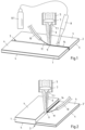
- the respective device comprises a base (not shown) on which two bands or blanks 1, 2 made of steel of the same or different material quality are arranged in such a way that their edges to be welded to one another butt together.
- At least one of the steel sheets 1, 2 is made of press-hardenable steel, preferably manganese-boron steel.
- the steel sheets 1, 2 are butt-joined with the smallest possible gap 3 of a few tenths of a millimeter.
- the width (width) of the gap 3 is, for example, less than 0.2 mm, preferably less than 0.15 mm. If the steel sheets 1, 2 are made of steel of different material grades, then one steel sheet 1 or 2 has, for example, a relatively soft deep-drawing quality, while the other steel sheet 2 or 1 consists of high-strength steel.
- the press-hardenable steel sheet 1 or 2 has a yield strength Re of preferably at least 300 MPa; its tensile strength Rm is, for example, at least 480 MPa, and its elongation at break Aso is preferably at least 10%.
- the press-hardened sheet steel After hot forming (press hardening), i.e. heating to an austenitization temperature of approx. 900°C to 950°C, forming at this temperature and subsequent rapid cooling, the press-hardened sheet steel has a yield point Re of approx. 1,100 MPa, a tensile strength Rm of approx 1,500 MPa to 2,000 MPa and an elongation at break Aso of about 5%.
- the steel sheets 1, 2 are provided with a metallic coating 4 made of aluminum. It is, for example, an Al-Si coating.
- the coating 4 is preferably applied to both sides of the base material, for example by hot-dip coating, in that a strip of press-hardenable steel, preferably manganese-boron steel, is passed through an Al-Si melt bath, excess coating material is blown off the strip and the coated strip is then post-treated, in particular is heated.
- the aluminum content of the coating 4 can range from 70% to 90% by weight.
- only one of the steel sheets 1, 2 to be welded can also have a coating 4 containing aluminum.
- the coating 4 optionally be applied only to one side of the steel sheet(s) 1, 2, for example by means of physical vapor deposition (PVD) or by means of an electrolytic coating process.
- the sheet thickness is, for example, in the range from 0.8 to 3.0 mm, preferably in the range from 1.8 mm to 3.0 mm, while the thickness of the metallic surface coating 4 on the respective side of the sheet is less than 100 ⁇ m, in particular less than 50 can be ⁇ m.
- a section of a laser welding head 5 is outlined above the steel sheets 1, 2, which is provided with an optical system for shaping and aligning a laser beam 6, in particular a focusing lens 7.
- the laser beam 6 is generated, for example, by means of an Nd:YAG laser system that supplies power in the range from 5 kW to 10 kW.
- a line 8 for supplying protective gas can optionally be assigned to the laser welding head 5 .
- the mouth of the shielding gas line 8 is or is directed, for example, essentially towards the freshly produced section of the weld seam 14, in such a way that the weld pool 9 itself is not, or at least not directly, acted upon by the flow of the shielding gas.
- 8.1 designates a compressed gas tank serving as a protective gas source. Pure argon or, for example, a mixture of argon, helium and/or carbon dioxide is preferably used as the protective gas.
- An alternative or further (not shown) embodiment of the fusion welding process provides that the underside or the side of the melt pool 9 facing away from the laser beam 6 and the underside of the weld seam 14 are exposed to protective gas.
- a powdered filler metal in the form of a gas-powder stream can also be fed to the molten pool 9.
- the powdered filler metal can have the same chemical composition as the filler wire 11 described above.
- One of the protective gases mentioned above is preferably used as the carrier gas for supplying the powdered filler metal into the molten bath 9 .
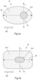
- the laser welding head 5 has one or more optical elements, by means of which a single laser focal spot 16 with different energy distribution is generated on the melt pool 9 in such a way that the laser focal spot 16 has a smaller laser focal spot area 16.1 and a larger laser focal spot area 16.2 (see also Figures 4a and 4b ).
- the larger laser focal spot area 16.2 irradiates an area that is at least twice, preferably at least 3 times, the area irradiated by the smaller laser focal spot area 16.1, with a higher laser energy output per unit area being introduced in the smaller laser focal spot area 16.1 than in the larger laser focal spot area 16.2 becomes.
- the smaller laser focal spot area 16.1 and the larger laser focal spot area 16.2 can have different energy levels that are independent of one another.
- a laser energy output in the range of 4 kW to 5 kW prevail, with this energy or power being distributed over a significantly larger area in the larger laser focal spot area 16.2.
- the smaller laser focal spot area 16.1 is essentially used for deep welding, while the larger laser focal spot area 16.2 supports the welding process.
- the larger laser focal spot area 16.2 has an elongated shape, for example an oval, elliptical or rectangular shape. Its longitudinal axis runs essentially in the respective welding direction WD, ie essentially parallel thereto.
- the smaller laser focal spot area 16.1 can have an essentially circular shape or also an elongated shape (see Figures 4a and 4b ).
- the optical element(s) of the laser welding head 5, by means of which the laser focal spot having a different energy distribution is generated, can be, for example, a diffractive or refractory optical element assigned to the focusing lens 7 and/or a smaller additional focusing lens 7.1 (see Fig Figures 1 and 2 ).
- the optical elements 7, 7.1 or 7, 7.2 of the laser welding head 5 are preferably designed in such a way that the position of the smaller laser focal spot area 16.1 can be adjusted within the larger laser focal spot area 16.2 relative to the latter.
- the position of the smaller laser focal spot area 16.1 can be adjusted within the larger laser focal spot area 16.2 in a direction (X direction and/or Y direction) running parallel and/or transverse to the welding direction WD.
- This setting is in the Figures 4a and 4b indicated schematically by dashed double arrows 18, 19.
- the smaller focusing lens 7.1 which is at least one diffractive or refractory Optical element or the light guide 7.2 in the laser welding head 5 mounted radially adjustable to the focusing lens 7.
- the position of the laser focal spot regions 16.1 and 16.2 relative to one another can be varied, for example by defocusing the laser beam 6.
- the larger laser focal spot area 16.2 has a longitudinal extent that is at least twice, preferably at least 2.5 times, particularly preferably at least 3 times the average diameter or largest diameter of the smaller laser focal spot area 16.1.
- This in 2 sketched embodiment differs from that in the figures 1 and 3 shown examples characterized in that the steel sheets 1, 2 'are of different thicknesses, so that there is a thickness jump d at the butt joint.
- one steel sheet 2' has a sheet thickness in the range from 0.8 mm to 1.2 mm
- the other steel sheet 1 has a sheet thickness in the range from 1.6 mm to 3.0 mm.
- the steel sheets 1, 2' to be connected to one another in a butt joint can also differ from one another in their material quality.
- the thicker blank 1 is made of high-strength steel, whereas the thinner steel blank 2' has a relatively soft deep-drawing quality.
- the steel sheets 1, 2' are also joined together with the smallest possible gap 3 of a few tenths of a millimeter.
- the molten bath 9 is not subjected to a stream of protective gas during the laser welding on its side facing the laser beam 6 .
- the molten bath 9 and the side of the weld seam 14 facing away from the laser beam 6 are preferably exposed to protective gas.
- the special or adapted energy distribution described in the individual laser focal spot 16 has the effect that the temperature distribution and thus the flows in the melt pool 9 change. This results in better homogenization of the weld seam 14. Welding speeds of 5 m/min and more are beneficial to the homogeneity of the weld seam 14.
- the filler wire 11 is preferably fed in at a speed of 40% to 90% of the welding speed.
- the additional wire 11 is preferably fed into the molten bath 9 in such a way that the wire 11 touches the smaller laser focal spot area 16.2 or is directed essentially directly at the smaller laser focal spot area 16.2.
- the wire feed is preferably sluggish (cf. 1 and 3 ).
- the filler wire 11 is fed to the molten bath 9 in such a way that the central axis of the wire 11 encloses an acute angle with the surface of the at least one steel sheet 1, 2 to be welded or of the steel sheets 1, 2 to be welded to one another, which angle is, for example, in is in a range from 10° to 45°, preferably in the range between 10° and 30°.
Description
Die Erfindung betrifft ein Verfahren zum Schmelzschweißen eines oder mehrerer Stahlbleche aus presshärtbarem Stahl, vorzugsweise Mangan-Bor-Stahl, wobei das oder mindestens eines der Stahlbleche eine metallische Beschichtung aus Aluminium, z. B. eine Al-Si-Beschichtung aufweist, und wobei das Schmelzschweißen unter Zuführung von Zusatzmaterial in das ausschließlich mittels mindestens eines Laserstrahls erzeugte Schmelzbad erfolgt.The invention relates to a method for fusion welding one or more steel sheets made of press-hardenable steel, preferably manganese-boron steel, wherein the steel sheet or at least one of the steel sheets has a metallic coating made of aluminum, e.g. B. has an Al-Si coating, and wherein the fusion welding is carried out with the supply of additional material in the melt pool generated exclusively by means of at least one laser beam.
Maßgeschneiderte Platinen aus Stahlblech (sogenannte Tailored Blanks) werden im Automobilbau verwendet, um hohe Anforderungen an die Crashsicherheit bei möglichst geringem Karosseriegewicht zu erfüllen. Hierzu werden einzelne Platinen oder Bänder unterschiedlicher Werkstoffgüte und/oder Blechdicke im Stumpfstoß durch Laserschweißen zusammengefügt. Auf diese Weise können verschiedene Stellen eines Karosseriebauteils an unterschiedliche Belastungen angepasst werden. So können an Stellen mit hoher Belastung dickeres oder auch höherfestes Stahlblech und an den übrigen Stellen dünnere Bleche oder auch Bleche aus relativ weichen Tiefziehgüten eingesetzt werden. Durch solche maßgeschneiderten Blechplatinen werden zusätzliche Verstärkungsteile an der Karosserie überflüssig. Das spart Material und ermöglicht, das Gesamtgewicht der Karosserie zu reduzieren.Tailor-made blanks made of sheet steel (so-called tailored blanks) are used in automobile construction to meet high crash safety requirements with the lowest possible body weight. For this purpose, individual blanks or strips of different material grades and/or sheet thicknesses are butt-joined together by laser welding. In this way, different points of a body component can be adapted to different loads. For example, thicker or higher-strength sheet steel can be used in places subject to high loads, and thinner sheets or sheets of relatively soft deep-drawn grades can be used in the other places. Such tailor-made sheet metal blanks make additional reinforcement parts on the body superfluous. This saves material and makes it possible to reduce the overall weight of the body.
Im modernen Karosseriebau werden Bleche aus Mangan-Bor-Stahl verwendet, die beim Warmumformen mit rascher Abkühlung hohe Festigkeiten erreichen. Im Anlieferungszustand, d. h. vor dem Warmumformen, weisen Mangan-Bor-Stähle eine Zugfestigkeit von ca. 600 MPa und ein ferritisch-perlitisches Gefüge auf. Durch Presshärten, d. h. durch Erwärmen auf Austenitisierungstemperatur vor dem Umformen und anschließendes rasches Abkühlen während oder nach dem Umformen kann ein vollständig martensitisches Gefüge eingestellt werden, welche Zugfestigkeiten bis zu 2000 MPa aufweisen kann. Häufig werden derartige Bauteile aus sogenannten Tailor welded Blanks gefertigt; das heißt es erfolgt eine Verbindung zwischen verschiedenen anforderungsgerechten Blechdicken und/oder Werkstoffgüten, üblicherweise mittels Laserstrahlschweißen.In modern car body construction, sheets of manganese-boron steel are used, which achieve high strength during hot forming and rapid cooling. In the delivered condition, ie before hot forming, manganese-boron steels have a tensile strength of approx. 600 MPa and a ferritic-pearlitic structure. A completely martensitic structure can be set by press hardening, ie by heating to the austenitization temperature before forming and subsequent rapid cooling during or after forming Tensile strengths of up to 2000 MPa. Such components are often made from so-called tailor-welded blanks; This means that there is a connection between different sheet metal thicknesses and/or material grades that meet the requirements, usually by means of laser beam welding.
In dem Warmumformungs- und Härtungsprozess, in welchem die Tailor welded Blanks weiterverarbeitet werden, soll deren Schweißnaht in der Regel in demselben Maße gehärtet werden wie die Grundwerkstoffe der Stahlplatinen, aus denen die Tailor welded Blanks zusammengesetzt sind. Dies zu gewährleisten, kann zum Beispiel beim Verschweißen von Stahlplatinen unterschiedlicher Dicke, bei denen sich am Fügestoß ein relativ großer Dickensprung ergibt, große Herausforderungen an den Warmumformungsprozess stellen. Das Prozessfenster (Parameterfenster) für einen adäquaten Härtungsprozess ist dann relativ klein. Zudem ist der Härtungsprozess empfindlich und muss sehr genau eingestellt werden, was oftmals produktionstechnische Einschränkungen für den Anwender mit sich bringt.In the hot forming and hardening process in which the tailor welded blanks are further processed, their weld seam should usually be hardened to the same extent as the base materials of the steel blanks from which the tailored welded blanks are composed. Ensuring this can pose major challenges for the hot forming process, for example when welding steel blanks of different thicknesses, where there is a relatively large jump in thickness at the joint. The process window (parameter window) for an adequate hardening process is then relatively small. In addition, the hardening process is sensitive and must be set very precisely, which often entails production-related restrictions for the user.
Weiter eingeschränkt wird das Schmelzschweißen von warmumformbaren, presshärtbaren Stahlblechen durch eine Oberflächenbeschichtung aus Aluminium. Eine solche Beschichtung, z. B. eine Aluminium-Silizium-Beschichtung, wird üblicherweise vorgesehen, um eine Verzunderung der Werkstücke bei der Warmumformung zu vermeiden. Auf die Qualität von Schweißnähten wirkt sich diese Oberflächenbeschichtung jedoch sehr negativ aus. Denn durch das Schmelzschweißen der beschichteten Stahlbleche wird neben dem Grundwerkstoff auch die aluminiumhaltige Oberflächenbeschichtung aufgeschmolzen und dadurch Aluminium in die Schweißnaht eingebracht. Liegt der Aluminiumgehalt in der Schweißnaht zwischen 2 und 10 Gew.-%, kommt es zur Bildung von ferritischen Bereichen (Phasen), die zu einer Herabsetzung der Festigkeit der Schweißnaht führen. Die Festigkeit der Schweißnaht liegt in solchen Fällen unter der des Grundwerkstoffs, so dass mit einem Versagen des betreffenden Bauteils in der Schweißnaht zu rechnen ist, unabhängig von der gefügten Blechdickenkombination.The fusion welding of hot-formable, press-hardenable steel sheets is further limited by a surface coating of aluminum. Such a coating, e.g. B. an aluminum-silicon coating is usually provided to avoid scaling of the workpieces during hot forming. However, this surface coating has a very negative effect on the quality of welds. Because the fusion welding of the coated steel sheets not only melts the base material, but also the aluminum-containing surface coating and thus aluminum is introduced into the weld seam. If the aluminum content in the weld is between 2 and 10% by weight, ferritic areas (phases) form, which lead to a reduction in the strength of the weld. In such cases, the strength of the weld seam is lower than that of the base material, so that failure of the component concerned in the weld seam is to be expected, regardless of the combination of sheet thicknesses joined.
Um die Ferritbildung zu verhindern, wird nach dem Stand der Technik eine zumindest teilweise Entfernung der Oberflächenbeschichtung im Randbereich der aneinander zu schweißenden Blechkanten vor dem Schweißprozess mittels mechanischer Werkzeuge oder Laserstrahlabtragung durchgeführt (vgl.
In der
Dieses bekannte Hybridschweißverfahren ist hinsichtlich des Energieverbrauchs aufgrund der Erzeugung des elektrischen Lichtbogens relativ aufwendig. Ferner ist die Schweißgeschwindigkeit vergleichsweise niedrig. Zudem weist eine durch Laser-Lichtbogen-Hybridschweißen erzeugte Schweißnaht eine für die weitere Umformung ungünstige Nahtform auf, welche gegebenenfalls einer Nachbearbeitung bedarf.This known hybrid welding method is relatively expensive in terms of energy consumption due to the generation of the electric arc. Furthermore, the welding speed is comparatively low. In addition, a laser-arc hybrid welding The weld seam produced has an unfavorable seam shape for further forming, which may require post-processing.
Aus der
In der
Die
Die
Der vorliegenden Erfindung liegt die Aufgabe zugrunde, ein Verfahren der eingangs genannten Art anzugeben, mit dem Stahlbleche, von denen mindestens ein Blech aus presshärtbarem Stahl hergestellt ist und eine metallische Beschichtung aufweist, die Aluminium enthält, derart gefügt werden können, dass deren Schweißnaht nach dem Warmumformen (Presshärten) eine dem Grundwerkstoff vergleichbare Festigkeit und Härte aufweist, wobei sich das Verfahren durch eine hohe Produktivität sowie einen vergleichsweise geringen Energieverbrauch auszeichnen soll. Insbesondere soll ein Verfahren der eingangs genannten Art angegeben werden, durch das die Härtbarkeit der Schweißnaht verbessert wird, und dies unabhängig davon, ob es sich bei den miteinander zu verschweißenden Stahlblechen um Stahlbleche gleicher oder verschiedener Werkstoffgüte und/oder um Stahlbleche unterschiedlicher Blechdicke handelt. Des Weiteren soll der anlagentechnische Aufwand zur Umsetzung des Verfahrens relativ gering sein. Es soll also ein Verfahren der eingangs genannten Art geschaffen werden, mit dem Bleche aus presshärtbarem Stahl, die eine Beschichtung auf Basis von Aluminium aufweisen, auf wirtschaftliche Weise miteinander verschweißt werden können und mit dem die Härtbarkeit der Schweißnaht verbessert wird, so dass das Prozessfenster für einen adäquaten Härtungsprozess vergrößert wird. Insbesondere soll eine hohe Schweißgeschwindigkeit ermöglicht werden.The present invention has for its object to provide a method of the type mentioned, with the steel sheets, of which at least one sheet is made of press-hardenable steel and has a metallic coating containing aluminum, can be joined in such a way that the weld seam after the Hot forming (press hardening) has a strength and hardness comparable to the base material, with the process being characterized by high productivity and a comparatively low energy consumption. In particular, a method of the type mentioned is to be specified, by which the hardenability of the weld seam is improved, regardless of whether the steel sheets to be welded together are steel sheets of the same or different material quality and/or steel sheets of different sheet thicknesses. Furthermore, the outlay in terms of plant technology for implementing the method should be relatively low. The aim is to create a method of the type mentioned at the outset with which sheets of press-hardenable steel that have an aluminum-based coating can be welded together economically and with which the hardenability of the weld seam is improved, so that the process window for an adequate curing process is increased. In particular, a high welding speed should be made possible.
Zur Lösung zumindest einiger Teilaspekte dieser Aufgabe wird ein Verfahren mit den in Anspruch 1 angegebenen Merkmalen vorgeschlagen. Vorteilhafte Ausgestaltungen des erfindungsgemäßen Verfahrens sind in den Unteransprüchen aufgezeigt.A method with the features specified in
Die Erfindung sieht bei einem Laserstrahlschweißverfahren der eingangs genannten Art vor, dass mittels eines oder mehrerer optischer Elemente ein einzelner Laserbrennfleck mit unterschiedlicher Energieverteilung an dem Schmelzbad derart erzeugt wird, dass der Laserbrennfleck einen kleineren Laserbrennfleckbereich und einen größeren Laserbrennfleckbereich aufweist, wobei der größere Laserbrennfleckbereich eine Fläche bestrahlt, die mindestens das 2-fache, vorzugsweise mindestens das 3-fache einer von dem kleineren Laserbrennfleckbereich bestrahlten Fläche beträgt, und in dem kleineren Laserbrennfleckbereich eine höhere Laserenergieleistung pro Flächeneinheit als in dem größeren Laserbrennfleckbereich eingebracht wird.In a laser beam welding method of the type mentioned at the outset, the invention provides that one or more optical elements are used to produce a single laser focal spot with different energy distribution on the melt pool in such a way that the laser focal spot has a smaller laser focal spot area and a larger laser focal spot area, with the larger laser focal spot area having a surface which is at least 2 times, preferably at least 3 times, an area irradiated by the smaller laser focal spot region, and a higher laser energy output per unit area is introduced into the smaller laser focal spot region than into the larger laser focal spot region.
Die beschriebene erfindungsgemäße Energieverteilung im Laserbrennfleck hat den Effekt, dass sich die Temperaturverteilung und somit die Strömungen im Schmelzbad gegenüber einer Temperaturverteilung und den Strömungen in einem mit einem herkömmlichen Laserschweißstrahl erzeugten Schmelzbad verändern. Der kleinere Laserbrennfleckbereich, der auch als Hauptbrennfleck bezeichnet werden kann und in welchem eine höhere Laserenergieleistung pro Flächeneinheit als in dem größeren Laserbrennfleckbereich (Nebenbrennfleck) eingebracht wird, dient im Wesentlichen der Tiefenverschweißung, während der größere Laserbrennfleckbereich den Schweißprozess unterstützt. Die über den kleineren Laserbrennfleckbereich eingebrachte Laserenergieleistung kann das gleiche oder in etwa das gleiche Niveau haben wie die über den größeren Laserbrennfleckbereich eingebrachte Laserenergieleistung. Beispielsweise können sowohl in den kleineren Laserbrennfleckbereich als auch in den größeren Laserbrennfleckbereich jeweils eine Laserenergieleistung von ca. 4,5 kW geleitet werden. Es liegt allerdings auch im Rahmen der Erfindung, dass die über den kleineren Laserbrennfleckbereich eingebrachte Laserenergieleistung ein deutlich unterschiedliches Niveau hat als die über den größeren Laserbrennfleckbereich eingebrachte Laserenergieleistung. Die in dem größeren Laserbrennfleckbereich eingebrachte Energie verteilt sich jeweils über eine größere Fläche als die in dem kleineren Laserbrennfleckbereich eingebrachte Energie. Die Wirkung der im größeren Laserbrennfleckbereich (Nebenbrennfleck) eingebrachten Energie unterscheidet sich somit von der Wirkung der Energie im Hauptbrennfleck. Durch diese unterschiedliche Energieeinbringung bzw. Energieverteilung lassen sich eine höhere Homogenisierung des Schmelzbades und damit eine hinsichtlich ihrer Härtbarkeit verbesserte Schweißnaht erzielen. Das Prozessfenster für einen adäquaten Härtungsprozess wird dadurch vergrößert.The described energy distribution according to the invention in the laser focal spot has the effect that the temperature distribution and thus the flows in the molten pool change compared to a temperature distribution and the flows in a melt pool generated with a conventional laser welding beam. The smaller laser focal spot area, which can also be referred to as the main focal spot and in which a higher laser energy output per unit area is introduced than in the larger laser focal spot area (secondary focal spot), is essentially used for deep welding, while the larger laser focal spot area supports the welding process. The power of laser energy delivered through the smaller laser focal spot area may be at or about the same level as the power of laser energy delivered through the larger laser spot area. For example, a laser energy output of approx. 4.5 kW can be directed both into the smaller laser focal spot area and into the larger laser focal spot area. However, it is also within the scope of the invention for the laser energy power introduced via the smaller laser focal spot area to have a significantly different level than the laser energy power introduced via the larger laser focal spot area. The energy introduced in the larger laser focal spot area is distributed over a larger area than the energy introduced in the smaller laser focal spot area. The effect of the energy introduced in the larger laser focal spot area (secondary focal spot) thus differs from the effect of the energy in the main focal spot. This different energy input or energy distribution makes it possible to achieve greater homogenization of the molten bath and thus a weld seam that is improved in terms of its hardenability. This increases the process window for an adequate curing process.
Die Energieverteilung wird derart gesteuert, dass der kleinere Laserbrennfleckbereich (Hauptbrennfleck) einen Tiefenschweißprozess erzeugt, während die Energie des äußeren oder größeren Laserbrennfleckbereichs den energetischen Schwellbereich zum Tiefenschweißen nicht überschreitet. Der Schwellbereich liegt dabei beispielsweise bei einer Leistungsdichte von ca. 1000 kW/cm2.The energy distribution is controlled such that the smaller laser focal spot area (main focal spot) produces a deep welding process, while the energy of the outer or larger laser focal spot area does not exceed the energy threshold area for deep welding. The threshold range is, for example, at a power density of approximately 1000 kW/cm 2 .
Das erfindungsgemäße Verfahren bietet insbesondere den Vorteil, dass bei ihm eine teilweise Entfernung der Aluminium enthaltenden Oberflächenbeschichtung im Randbereich der aneinander zu schweißenden Blechkanten vor dem Schweißprozess nicht notwendig ist. Dementsprechend sieht eine bevorzugte Ausgestaltung des erfindungsgemäßen Verfahrens vor, dass dieses im Wesentlichen ohne vorheriges Entfernen, insbesondere ohne vorheriges teilweises Entfernen der Aluminium enthaltenden Oberflächenbeschichtung vom Randbereich der aneinander zu schweißenden Blechkanten durchgeführt wird.The method according to the invention offers the particular advantage that a partial removal of the aluminum-containing surface coating in the edge region of the sheet metal edges to be welded to one another before the welding process is not necessary. Accordingly, a preferred embodiment of the method according to the invention provides that this is carried out essentially without prior removal, in particular without prior partial removal of the aluminum-containing surface coating from the edge region of the sheet metal edges to be welded to one another.
Im Vergleich zum Laserstrahlschweißen nach vorherigem Entschichten der Ränder der im Stumpfstoß zu verschweißenden beschichteten Stahlbleche ermöglicht das erfindungsgemäße Verfahren eine optimierte Schweißnahtgeometrie, und zwar einen größeren tragenden Blechkantenquerschnitt. Dies ist insbesondere bei späteren dynamischen Belastungen der Schweißnaht von Vorteil.Compared to laser beam welding after prior decoating of the edges of the coated steel sheets to be butt-welded, the method according to the invention enables an optimized weld seam geometry, specifically a larger load-bearing sheet edge cross-section. This is particularly advantageous in the case of subsequent dynamic loads on the weld seam.
Ein weiterer Vorteil des erfindungsgemäßen Verfahrens besteht, wie sich bei internen Versuchen gezeigt hat, in der deutlich geringeren Schweißspritzerbildung. Ein Grund für die geringere Schweißspritzerbildung wird seitens der Erfinder in der gezielt unterschiedlichen Energieverteilung im Laserbrennfleck und der daraus resultierenden speziellen Schmelzbadströmung gesehen.A further advantage of the method according to the invention, as has been shown in internal tests, is the significantly reduced formation of welding spatter. The inventors see one reason for the reduced formation of weld spatter in the deliberately different energy distribution in the laser focal spot and the resulting special melt pool flow.
Die Laserstrahlenergie lässt sich weitgehend variabel in dem Laserbrennfleck verteilen. Die unterschiedliche Energieverteilung bzw. angepasste Energieeinbringung im Laserbrennfleck wird bei dem erfindungsgemäßen Verfahren mittels eines oder mehrerer optischer Elemente erreicht. Beispielsweise kann dies über ein oder mehrere diffraktorische oder refraktorische Optikelemente und/oder direkt durch die Verwendung einer oder mehrerer entsprechend angeordneter Lichtleiterfasern verwirklicht werden. Ein entsprechend modifizierter Laserschweißkopf kann beispielsweise zwei unterschiedliche diffraktorische oder refraktorische Optikelemente, insbesondere Linsen aufweisen, die relativ zueinander axial und/oder radial verschoben werden können. Ein entsprechend modifizierter Laserschweißkopf lässt sich in kompakter Bauweise realisieren.The laser beam energy can be distributed largely variably in the laser focal spot. The different energy distribution or adapted energy input in the laser focal spot is achieved in the method according to the invention by means of one or more optical elements. For example, this can be implemented via one or more diffractive or refractory optical elements and/or directly by using one or more appropriately arranged optical fibers. A correspondingly modified laser welding head can, for example, have two different diffractive or refractory optical elements, in particular lenses, which are axial and/or axial relative to one another can be moved radially. A correspondingly modified laser welding head can be implemented in a compact design.
Eine andere Möglichkeit zur Erzeugung einer unterschiedlichen Energieverteilung in dem einzelnen Laserbrennfleck besteht darin, den Laserstrahl zu teilen und die dadurch erhaltenen Laserteilstrahlen durch unterschiedliche diffraktorische oder refraktorische Optikelemente, insbesondere Linsen zu leiten, wobei die so modulierten Laserteilstrahlen anschließend wieder zu einem Laserstrahl zusammengeführt werden und der so zusammengesetzte Laserstrahl auf den Fügestoß der miteinander zu verschweißenden Stahlblechkanten gerichtet wird. Auch ein solcher modifizierter Laserschweißkopf lässt sich in kompakter Bauweise realisieren.Another way to generate a different energy distribution in the individual laser focal spot is to split the laser beam and direct the resulting partial laser beams through different diffractive or refractory optical elements, in particular lenses, with the partial laser beams modulated in this way then being combined again into one laser beam and the The laser beam composed in this way is directed at the joint of the sheet steel edges to be welded together. Such a modified laser welding head can also be implemented in a compact design.
Noch eine weitere Möglichkeit zur Erzeugung einer unterschiedlichen Energieverteilung in dem einzelnen Laserbrennfleck besteht darin, zwei oder mehr unterschiedliche Laserstrahlen, die beispielsweise mittels ähnlicher oder unterschiedlicher Laserlichtquellen erzeugt werden, in einer Laserstrahloptik derart zusammenzuführen, dass der daraus resultierende Laserstrahl einen einzelnen, zusammengesetzten Laserbrennfleck mit unterschiedlicher Energieverteilung erzeugt.Yet another way of generating a different energy distribution in the individual laser focal point is to combine two or more different laser beams, which are generated, for example, by means of similar or different laser light sources, in a laser beam optic in such a way that the resulting laser beam forms a single, composite laser focal point with a different power distribution generated.
Die Vorrichtung zur Führung des Laserschweißkopfes bzw. des jeweiligen zu verschweißenden Werkstücks kann dabei in den voranstehend angegebenen Ausgestaltungen der Erfindung jeweils in herkömmlicher Art ausgeführt werden, d. h. das erfindungsgemäße Verfahren erfordert keine aufwendigere mechanische Anordnung oder aufwendigere Führungsvorrichtung als dies bei herkömmlichen Laserschweißanlagen zur Ausführung eines gattungsgemäßen Verfahrens zum Schmelzschweißen eines oder mehrerer Stahlbleche aus presshärtbarem Stahl der Fall ist. Eine Anlage zum Laser-Lichtbogen-Hybridschweißen, wie es z. B. aus der
Des Weiteren ermöglicht das erfindungsgemäße Verfahren insbesondere im Vergleich zu einem Laser-Lichtbogen-Hybridschweißen hohe Schweißgeschwindigkeiten bei relativ geringem Energieverbrauch.Furthermore, the method according to the invention enables high welding speeds with relatively low energy consumption, in particular in comparison to laser-arc hybrid welding.
Eine vorteilhafte Ausgestaltung der Erfindung ist dadurch gekennzeichnet, dass der Laserstrahl bei dem Schmelzschweißen im Wesentlichen oszillationsfrei betrieben wird. Im Wesentlichen oszillationsfrei bedeutet, dass der Laserstrahl nicht gewollt in Oszillation versetzt wird. Hierdurch lassen sich insbesondere relativ hohe Schweißgeschwindigkeiten erreichen. Ferner kann somit die Lagerung des Laserschweißkopfes bzw. die Halterung der optischen Elemente im Laserschweißkopf relativ einfach verwirklicht werden.An advantageous embodiment of the invention is characterized in that the laser beam is operated essentially without oscillation during fusion welding. Substantially oscillation-free means that the laser beam is not set to oscillate intentionally. In this way, in particular, relatively high welding speeds can be achieved. Furthermore, the mounting of the laser welding head or the mounting of the optical elements in the laser welding head can thus be realized in a relatively simple manner.
Eine weitere vorteilhafte Ausgestaltung der Erfindung sieht vor, dass das oder die optischen Elemente, mittels dem/denen der eine unterschiedliche Energieverteilung aufweisende Laserbrennfleck erzeugt wird, derart ausgeführt ist/sind, dass die Position des kleineren Laserbrennfleckbereichs innerhalb des größeren Laserbrennfleckbereichs, relativ zu letzterem einstellbar ist. Somit kann die unterschiedliche Energieeinbringung bzw. unterschiedliche Energieverteilung in dem Laserbrennfleck optimal an die jeweiligen Schweißbedingungen angepasst werden. Beispielsweise wird die Position des kleineren Laserbrennfleckbereichs innerhalb des größeren Laserbrennfleckbereichs in einer parallel und/oder quer zur Schweißrichtung verlaufenden Richtung eingestellt. Vorzugsweise wird die Position des kleineren Laserbrennfleckbereichs innerhalb des größeren Laserbrennfleckbereichs so eingestellt, dass der kleinere Laserbrennfleckbereich im Wesentlichen in der Mitte des größeren Laserbrennfleckbereichs oder in Richtung der Schweißrichtung gesehen vorlaufend vor der Mitte des größeren Laserbrennfleckbereichs angeordnet ist.A further advantageous embodiment of the invention provides that the optical element or elements by means of which the laser focal spot with a different energy distribution is/are generated is/are designed in such a way that the position of the smaller laser focal spot area within the larger laser focal spot area can be adjusted relative to the latter is. Thus, the different energy input or different energy distribution in the laser focal spot can be optimally adapted to the respective welding conditions. For example, the position of the smaller laser focal spot area is adjusted within the larger laser focal spot area in a direction parallel and/or transverse to the welding direction. Preferably, the position of the smaller laser focal spot area is adjusted within the larger laser focal spot area so that the smaller laser focal spot area in the Substantially in the center of the larger laser focal spot area or in front of the center of the larger laser focal spot area as viewed in the direction of the welding direction.
Die Form des größeren Laserbrennfleckbereichs und/oder des kleineren Laserbrennfleckbereichs kann beispielsweise rund, elliptisch, quadratisch oder rechteckig sein. Eine im Wesentlichen runde Form des größeren Laserbrennfleckbereichs und/oder des kleineren Laserbrennfleckbereichs kann sich insbesondere dann ergeben, wenn bei dem erfindungsgemäßen Verfahren die unterschiedliche Energieverteilung bzw. angepasste Energieeinbringung im Laserbrennfleck mittels eines oder mehrerer entsprechend angeordneter Lichtleiterfasern verwirklicht wird.The shape of the larger laser focal spot area and/or the smaller laser focal spot area can be round, elliptical, square or rectangular, for example. A substantially round shape of the larger laser focal spot area and/or the smaller laser focal spot area can result in particular if, in the method according to the invention, the different energy distribution or adapted energy input in the laser focal spot is realized by means of one or more appropriately arranged optical fibers.
Nach einer vorteilhaften Ausgestaltung der Erfindung weist der größere Laserbrennfleckbereich eine längliche Form, insbesondere eine ovale, elliptische oder rechteckige Form auf, wobei eine Längsachse des größeren Laserbrennfleckbereichs im Wesentlichen in der Schweißrichtung verläuft. Hierdurch ergibt sich am Fügestoß eine relativ große Schweißbadfläche, so dass bei einer bestimmten Schweißgeschwindigkeit mehr Zeit für ein Ausgasen des Schweißbades bis zur Erstarrung der Schweißnaht zur Verfügung steht.According to an advantageous embodiment of the invention, the larger laser focal spot area has an elongated shape, in particular an oval, elliptical or rectangular shape, with a longitudinal axis of the larger laser focal spot area running essentially in the welding direction. This results in a relatively large weld pool area at the joint, so that at a certain welding speed there is more time available for outgassing of the weld pool until the weld seam solidifies.
Eine weitere vorteilhafte Ausgestaltung der Erfindung ist dadurch gekennzeichnet, dass der größere Laserbrennfleckbereich eine Längserstreckung aufweist, die mindestens das 2-fache, vorzugsweise mindestens das 2,5-fache, besonders bevorzugt mindestens das 3-fache des mittleren Durchmessers oder größten Durchmessers des kleineren Laserbrennfleckbereichs beträgt. Versuche seitens der Erfinder haben ergeben, dass sich auf diese Weise eine sehr homogene Verteilung von in das Schweißbad eingeflossenem und in der Schweißnaht verbleibendem Aluminium erzielen lässt.A further advantageous embodiment of the invention is characterized in that the larger laser focal spot area has a longitudinal extension that is at least twice, preferably at least 2.5 times, particularly preferably at least 3 times the average diameter or largest diameter of the smaller laser focal spot area amounts to. Tests by the inventors have shown that a very homogeneous distribution of aluminum that has flowed into the weld pool and remains in the weld seam can be achieved in this way.
Erfindungsgemäß erfolgt das Schmelzschweißen unter Zuführung von Zusatzmaterial (auch Schweißzusatz genannt) in das ausschließlich mittels mindestens eines Laserstrahls erzeugte Schmelzbad. Der Schweißzusatz hat mehrere Aufgaben. Zum einen kann durch geeignete Legierungselemente des Schweißzusatzes die ferritbildende Wirkung von aus der Beschichtung in die Schweißschmelze eingeflossenem Aluminium minimiert und somit die Härtbarkeit der Schweißnaht verbessert werden. Zum anderen wird durch die Zugabe von im Wesentlichen aluminiumfreien Zusatzmaterial der Aluminiumgehalt der Schweißnaht minimiert. Zudem kommt es zu vermehrten oder stärkeren Strömungsbewegungen im Schmelzbad durch das darin eingebrachte Zusatzmaterial und somit zu einer Homogenisierung der Schweißnahtzusammensetzung.According to the invention, the fusion welding takes place with the supply of additional material (also called welding filler) into the melt pool that is produced exclusively by means of at least one laser beam. The filler metal has several tasks. On the one hand, the ferrite-forming effect of aluminum flowing from the coating into the weld pool can be minimized by using suitable alloying elements in the filler metal, and thus the hardenability of the weld seam can be improved. On the other hand, the aluminum content of the weld seam is minimized by the addition of essentially aluminum-free additional material. In addition, there are increased or stronger flow movements in the melt pool due to the additional material introduced therein and thus to a homogenization of the weld seam composition.
Zusatzmaterial wird dem Schmelzbad vorzugsweise in Form eines Drahtes oder Pulvers zugeführt. Zusatzmaterial in Form eines Drahtes lässt sich dem Schmelzbad sehr energieeffizient und mit hoher Mengengenauigkeit zuführen. Durch Einbringen von pulverförmigem Schweißzusatz einer geeigneten Partikelgröße ist ein sehr gleichmäßiges Vermischen des Schweißzusatzes im Schmelzbad möglich. Typischerweise liegt die Dauer der Schmelzphase beim Laserschweißen in einem Bereich von nur etwa 6 ms bis 125 ms. Da die Schweißzeit beim Laserschweißen relativ kurz ist, lässt sich mit pulverförmigem Schweißzusatz eine bessere Durchmischung mit dem zu verschweißenden Stahl erzielen als bei Verwendung von Zusatzdraht. Durch die Verwendung eines pulverförmigen Schweißzusatzes, der relativ kleine Partikel, vorzugsweise kleine Metallpartikel aufweist, kann eine weitgehend homogene Legierungsdurchmischung auch in sehr kurzen Zeiträumen der Schmelzphase erzielt werden. Die Partikel des pulverförmigen Schweißzusatzes haben beispielsweise eine Partikelgröße im Bereich von 20 µm bis 160 µm, vorzugsweise im Bereich von 20 µm bis 160 µm.Filler material is preferably fed into the weld pool in the form of a wire or powder. Additional material in the form of a wire can be fed into the weld pool in a very energy-efficient manner and with high quantity accuracy. By introducing powdered filler metal of a suitable particle size, it is possible to mix the filler metal very evenly in the weld pool. Typically, the duration of the melting phase in laser welding is in a range from only about 6 ms to 125 ms. Since the welding time for laser welding is relatively short, a better mixing with the steel to be welded can be achieved with powdered filler metal than with the use of filler wire. Through the use of a powdered filler metal, which has relatively small particles, preferably small metal particles, a largely homogeneous mixing of the alloy can be achieved even in very short periods of time during the melting phase. The particles of the welding filler powder have, for example, a particle size in the range from 20 μm to 160 μm, preferably in the range from 20 μm to 160 μm.
Vorzugsweise wird das pulverförmige Zusatzmaterial in Form eines Gas-Pulverstroms über mindestens einen Strömungskanal zugeführt, wobei der aus dem Strömungskanal austretende Gas-Pulverstrom auf das Schmelzbad gerichtet ist und eine Austrittsgeschwindigkeit von mindestens 2 m/s, vorzugsweise mindestens 10 m/s, besonders bevorzugte mindestens 15 m/s aufweist, so dass sich eine turbulente Durchmischung des Schweißzusatzes mit dem Schmelzbad ergibt, bei der sich im Schmelzbad Strömungswirbel ergeben. Diese Strömungswirbel (Turbulenzen) werden insbesondere durch die Kinetik des Gas-Pulverstroms bewirkt. Eine Obergrenze der Austrittsgeschwindigkeit des auf das Schmelzbad gerichteten Gas-Pulverstroms kann beispielsweise bei 50 m/s, insbesondere bei 40 m/s oder bei 30 m/s liegen.The powdered additional material is preferably supplied in the form of a gas-powder stream via at least one flow channel, with the gas-powder stream emerging from the flow channel being directed onto the molten bath and a Exit speed of at least 2 m/s, preferably at least 10 m/s, particularly preferably at least 15 m/s, so that there is a turbulent mixing of the filler metal with the molten pool, resulting in flow vortices in the molten pool. These flow vortices (turbulence) are caused in particular by the kinetics of the gas-powder flow. An upper limit of the exit speed of the gas-powder flow directed onto the molten bath can be, for example, 50 m/s, in particular 40 m/s or 30 m/s.
Vorzugsweise ist das bei der Durchführung des erfindungsgemäßen Verfahrens dem Schmelzbad zugeführte Zusatzmaterial im Wesentlichen aluminiumfrei. Unter einem aluminiumfreien oder im Wesentlichen aluminiumfreien Zusatzmaterial wird im Kontext der Erfindung ein Schweißzusatz verstanden, der bis auf unvermeidbare Verunreinigungen oder unvermeidbare Spurenanteile kein Aluminium enthält.The additional material fed to the molten bath when carrying out the method according to the invention is preferably essentially aluminum-free. In the context of the invention, an aluminum-free or essentially aluminum-free filler material is understood to mean a filler metal that contains no aluminum apart from unavoidable impurities or unavoidable trace amounts.
Zur Verbesserung der Härtbarkeit der Schweißnaht sieht eine weitere Ausgestaltung der Erfindung vor, dass das Zusatzmaterial mindestens ein Legierungselement aus einer Nickel, Chrom und/oder Kohlenstoff umfassenden Gruppe enthält. Um die Härtbarkeit der Schweißnaht zu erhöhen, enthält das Zusatzmaterial vorzugsweise 5 bis 12 Gew.-% Ni, 5 bis 25 Gew.-% Cr und 0,05 bis 0,4 Gew.-% C, optional mindestens ein weiteres Legierungselement, Rest Eisen und unvermeidbare Verunreinigungen. Ein Chromgehalt des Zusatzmaterials im Bereich von 5 bis 25 Gew.-% ist günstig, um die kritische Abkühlgeschwindigkeit der Schweißnaht herabzusetzen und somit die Härtbarkeit der Schweißnaht weiter zu verbessern.In order to improve the hardenability of the weld seam, a further embodiment of the invention provides that the additional material contains at least one alloying element from a group comprising nickel, chromium and/or carbon. In order to increase the hardenability of the weld, the filler material preferably contains 5 to 12% by weight Ni, 5 to 25% by weight Cr and 0.05 to 0.4% by weight C, optionally at least one other alloying element, remainder Iron and unavoidable impurities. A chromium content of the additional material in the range from 5 to 25% by weight is favorable in order to reduce the critical cooling rate of the weld seam and thus further improve the hardenability of the weld seam.
Eine bevorzugte Ausgestaltung des erfindungsgemäßen Verfahrens ist dadurch gekennzeichnet, dass das dabei verwendete Zusatzmaterial folgende Zusammensetzung aufweist: 0,05 bis 0,4 Gew.-% C, 0 bis 2,0 Gew.-% Si, 0 bis 3,0 Gew.-% Mn, 4 bis 25 Gew.-% Cr, 0 bis 0,5 Gew.-% Mo, und 5 bis 12 Gew.-% Ni, Rest Fe und unvermeidbare Verunreinigungen. Interne Versuche haben ergeben, dass sich mit einem solchen Zusatzmaterial unter Anwendung des erfindungsgemäßen Verfahrens sehr zuverlässig eine vollständige Umwandlung der Schweißnaht in ein martensitisches Gefüge beim anschließenden Warmumformen (Presshärten) des Tailored Blanks sicherstellen lässt.A preferred embodiment of the method according to the invention is characterized in that the additional material used has the following composition: 0.05 to 0.4% by weight C, 0 to 2.0% by weight Si, 0 to 3.0% by weight -% Mn, 4 to 25 wt% Cr, 0 to 0.5 wt% Mo, and 5 to 12 wt% Ni, balance Fe and unavoidable impurities. Internal tests have shown that with such an additional material using the method according to the invention, a complete conversion of the weld seam into a very reliable martensitic structure can be ensured during the subsequent hot forming (press hardening) of the tailored blank.
Eine weitere vorteilhafte Ausgestaltung des erfindungsgemäßen Verfahrens ist dadurch gekennzeichnet, dass das Zusatzmaterial, vorzugsweise in Form eines Drahtes, derart in das Schmelzbad zugeführt wird, dass das Zusatzmaterial unmittelbar in den kleineren Laserbrennfleckbereich zugeführt wird. Das Zusatzmaterial, vorzugsweise in Form eines Drahtes, tangiert dabei den kleineren Laserbrennfleckbereich oder ist im Wesentlichen auf den kleineren Laserbrennfleckbereich gerichtet. So wird sichergestellt, dass das aufgeschmolzene Zusatzmaterial beim Tiefschweißen die Dampfkappilare im Schmelzbad umströmt. Hierdurch werden eine bessere Vermischung des Zusatzmaterials mit dem im Fügestoß, d. h. Stumpfstoß oder Überlappstoß aufgeschmolzenen Stahlblechmaterials und damit eine homogenere Schweißnaht erzielt.A further advantageous embodiment of the method according to the invention is characterized in that the additional material, preferably in the form of a wire, is fed into the molten bath in such a way that the additional material is fed directly into the smaller laser focal spot area. The additional material, preferably in the form of a wire, touches the smaller laser focal spot area or is essentially directed towards the smaller laser focal spot area. This ensures that the melted filler material flows around the vapor capillaries in the weld pool during deep penetration welding. This enables better mixing of the additional material with the material in the joint, d. H. Butt joint or lap joint of melted steel sheet material and thus a more homogeneous weld seam is achieved.
Eine weitere vorteilhafte Ausgestaltung des erfindungsgemäßen Verfahrens ist dadurch gekennzeichnet, dass das Zusatzmaterial, vorzugsweise in Form eines Drahtes, schleppend zugeführt wird. Eine schleppende Zusatzmaterialzuführung, insbesondere Drahtzuführung, bedeutet, dass das Zusatzmaterial in Schweißrichtung gesehen dem Schmelzbad vorlaufend bzw. dem kleineren Laserbrennfleckbereich von vorne zugeführt wird. Auch durch diese Ausgestaltung werden eine bessere Vermischung des Zusatzmaterials mit dem im Fügestoß, d. h. Stumpfstoß oder Überlappstoß aufgeschmolzenen Stahlblechmaterials und damit eine homogenere Schweißnaht erzielt.A further advantageous embodiment of the method according to the invention is characterized in that the additional material, preferably in the form of a wire, is fed in slowly. A sluggish feed of additional material, in particular wire feed, means that the additional material is fed ahead of the weld pool or the smaller laser focal spot area from the front, seen in the direction of welding. This configuration also allows for better mixing of the additional material with the material in the joint, d. H. Butt joint or lap joint of melted steel sheet material and thus a more homogeneous weld seam is achieved.
Eine weitere vorteilhafte Ausgestaltung des erfindungsgemäßen Verfahrens ist dadurch gekennzeichnet, dass das in Form eines Drahtes zugeführte Zusatzmaterial dem Schmelzbad derart zugeführt wird, dass die Mittelachse des Drahtes mit der Oberfläche des mindestens einen zu verschweißenden Stahlblechs bzw. der miteinander zu verschweißenden Stahlbleche einen spitzen Winkel von kleiner 50°, bevorzugt kleiner 45°, besonders bevorzugt kleiner 30°, insbesondere zwischen 10° und 30° einschließt. Hierdurch lässt sich eine optimale Zuführung des Zusatzmaterials in den Tiefschweißbereich, insbesondere in Richtung der Dampfkappilare erzielen.A further advantageous embodiment of the method according to the invention is characterized in that the additional material supplied in the form of a wire is supplied to the molten bath in such a way that the central axis of the wire forms an acute angle of less than 50°, preferably less than 45°, particularly preferably less than 30°, in particular between 10° and includes 30°. This allows the additional material to be optimally fed into the deep welding area, in particular in the direction of the steam capillaries.
Nach einer weiteren vorteilhaften Ausgestaltung wird das Zusatzmaterial, vorzugsweise in Form eines Drahtes, vor dem Zuführen (Einfließen) in das Schmelzbad mittels einer Heizvorrichtung auf eine Temperatur von mindestens 60°C, vorzugsweise auf mindestens 100°C, vorzugsweise auf mindestens 150°C, insbesondere auf mindestens 180° erhitzt. Hierdurch ist im Vergleich zur Verwendung eines nicht erhitzten Zusatzdrahtes eine deutlich höhere Schweißgeschwindigkeit möglich. Denn die Spitze des erhitzten Zusatzdrahtes lässt sich mit dem Laserstrahl schneller schmelzen. Darüber hinaus wird der Schweißprozess durch das Erhitzen des Zusatzdrahtes vor dem Zuführen in die Schweißschmelze stabiler. Die Obergrenze der Temperatur des vorerhitzten Drahtes liegt unterhalb der Temperatur, bei welcher der Draht seine Formstabilität verliert oder diese für eine zuverlässige Drahtzuführung zu gering ist. Die Obergrenze der Drahtvorerhitzung liegt beispielsweise im Bereich von ca. 250°C bis 300°C.According to a further advantageous embodiment, the additional material, preferably in the form of a wire, is heated to a temperature of at least 60° C., preferably at least 100° C., preferably at least 150° C. in particular heated to at least 180°. As a result, a significantly higher welding speed is possible compared to using an unheated filler wire. Because the tip of the heated filler wire can be melted faster with the laser beam. In addition, by heating the filler wire before feeding it into the weld puddle, the welding process becomes more stable. The upper limit of the temperature of the preheated wire is below the temperature at which the wire loses its dimensional stability or is too low for reliable wire feeding. For example, the upper limit of wire preheating is in the range of about 250°C to 300°C.
Vorzugsweise wird ein Mangan-Bor-Stahl als presshärtbarer Stahl verwendet. In einer bevorzugten Ausgestaltung des erfindungsgemäßen Verfahrens wird das zu verschweißende Stahlblech oder mindestens eines der miteinander zu verschweißenden Stahlbleche so ausgewählt, dass es einen presshärtbaren Stahl folgender Zusammensetzung aufweist: 0,10 bis 0,50 Gew.-% C, max. 0,40 Gew.-% Si, 0,50 bis 2,0 Gew.-% Mn, max. 0,025 Gew.-% P, max. 0,010 Gew.-% S, max. 0,60 Gew.-% Cr, max. 0,50 Gew.-% Mo, max. 0,050 Gew.-% Ti, 0,0008 bis 0,0070 Gew.-% B, und min. 0,010 Gew.-% Al, Rest Fe und unvermeidbare Verunreinigungen. Die aus einem solchen Stahlblech gefertigten Bauteile weisen nach dem Presshärten eine hohe Festigkeit auf. Bleche aus unterschiedlichen oder identischen Mangan-Bor-Stählen können mit dem erfindungsgemäßen Verfahren miteinander verschweißt werden, um maßgeschneiderte, durch Presshärten maximierte Festigkeiten aufweisende Blechhalbzeuge bereitzustellen.A manganese-boron steel is preferably used as the press-hardenable steel. In a preferred embodiment of the method according to the invention, the steel sheet to be welded or at least one of the steel sheets to be welded together is selected such that it has a press-hardenable steel with the following composition: 0.10 to 0.50% by weight C, max. 0.40 wt% Si, 0.50 to 2.0 wt% Mn, max 0.025 wt% P, max 0.010 wt% S, max 0.60 wt% Cr, max 0.50 wt% Mo, max 0.050 wt% Ti, 0.0008 to 0.0070 wt% B, and min 0.010 wt% Al, balance Fe and unavoidable impurities. The components made from such a sheet steel have a high strength after press hardening. Sheets of different or identical manganese-boron steels can be welded to one another using the method according to the invention in order to provide tailor-made sheet metal semi-finished products that have maximum strength through press hardening.
Das erfindungsgemäße Verfahren kann nicht nur beim Aneinanderfügen mehrerer Stahlplatinen gleicher oder unterschiedlicher Blechdicke im Stumpfstoß zum Einsatz kommen, von denen mindestens eine Platine aus presshärtbarem Stahl hergestellt und mit einer Aluminium enthaltenden Beschichtung versehen ist, sondern auch beim Laserstrahlschweißen eines einzelnen platten- oder bandförmigen Stahlblechs aus presshärtbarem Stahl, vorzugsweise Mangan-Bor-Stahl, das eine Aluminium enthaltende Beschichtung aufweist, wobei im letztgenannten Fall die miteinander zu verschweißenden Blechkanten durch Umformen, beispielsweise durch Abkanten oder Rollformen, aufeinander zu bewegt werden, so dass sie schließlich einander zugewandt im Stumpfstoß angeordnet sind.The method according to the invention can be used not only when joining several steel blanks of the same or different sheet thicknesses in a butt joint, of which at least one blank is made of press-hardenable steel and provided with a coating containing aluminum, but also when laser beam welding a single plate or strip-shaped steel sheet press-hardenable steel, preferably manganese-boron steel, which has a coating containing aluminum, in which case the sheet metal edges to be welded together are moved towards one another by forming, for example by folding or roll forming, so that they are finally arranged facing one another in the butt joint .
Des Weiteren kann das erfindungsgemäße Verfahren auch beim Laserstrahlschweißen eines oder mehrerer Stahlbleche aus presshärtbarem Stahl, vorzugsweise Mangan-Bor-Stahl, im Überlappstoß angewendet werden.Furthermore, the method according to the invention can also be used for laser beam welding of one or more steel sheets made of press-hardenable steel, preferably manganese-boron steel, in a lap joint.
Eine weitere vorteilhafte Ausgestaltung des erfindungsgemäßen Verfahrens ist dadurch gekennzeichnet, dass das oder die Stahlbleche im Stumpfstoß gefügt wird/werden, wobei an dem zu fügenden Stumpfstoß ein möglichst geringer Spalt, vorzugsweise quasi ein "technischer Nullspalt", mit einer durchschnittlichen Spaltbreite im Bereich von 0,01 bis 0,15 mm, vorzugsweise im Bereich von 0,06 bis 0,15 mmeingestellt wird.A further advantageous embodiment of the method according to the invention is characterized in that the steel sheet(s) is/are joined in a butt joint, with the smallest possible gap at the butt joint to be joined, preferably a "technical zero gap", with an average gap width in the range of 0 .01 to 0.15 mm, preferably in the range of 0.06 to 0.15 mm.
Eine weitere bevorzugte Ausgestaltung des erfindungsgemäßen Verfahrens sieht vor, dass das oder die Stahlbleche mit einer Schweißgeschwindigkeit von mindestens 4 m/min, vorzugsweise von mindestens 5 m/min, besonders bevorzugt mit einer Schweißgeschwindigkeit im Bereich von 6 bis 12 m/min gefügt wird/werden.A further preferred embodiment of the method according to the invention provides that the steel sheet(s) is/are joined at a welding speed of at least 4 m/min, preferably at least 5 m/min, particularly preferably at a welding speed in the range from 6 to 12 m/min. become.
Zur Erzielung einer möglichst homogenen, einwandfrei härtbaren Schweißnaht sowie einer sehr guten Schweißnahtgeometrie ist es vorteilhaft, wenn nach einer weiteren bevorzugten Ausgestaltung des erfindungsgemäßen Verfahrens das Zusatzmaterial in Form eines Drahtes zugeführt wird, wobei die Drahtzufuhr mit einer Zufuhrgeschwindigkeit im Bereich von 40 % bis 90 % der Schweißgeschwindigkeit erfolgt.To achieve the most homogeneous possible, properly hardenable weld and a very good weld geometry, it is advantageous if, according to a further preferred embodiment of the method according to the invention, the additional material is supplied in the form of a wire, the wire supply with a Feed speed is in the range of 40% to 90% of the welding speed.
Eine weitere Ausgestaltung der Erfindung sieht vor, dass das Schmelzbad während des Laserschweißens zumindest an seiner dem Laserstrahl abgewandten Seite mit Schutzgas beaufschlagt wird. Das Schutzgas schützt die Schweißschmelze vor Oxidation, die eine Schwächung der Schweißnaht zur Folge hätte. Bei dem Schutzgas kann es sich beispielsweise um reines Argon, COz, Helium, Stickstoff oder ein Mischgas aus Argon, Helium, Stickstoff und/oder COz handeln.A further embodiment of the invention provides that during the laser welding the molten pool is exposed to protective gas at least on its side facing away from the laser beam. The shielding gas protects the weld pool from oxidation, which would weaken the weld seam. The protective gas can be, for example, pure argon, CO2, helium, nitrogen or a mixed gas of argon, helium, nitrogen and/or CO2.
Eine weitere vorteilhafte Ausgestaltung der Erfindung sieht vor, dass das Schmelzbad während des Laserschweißens zumindest an seiner dem Laserstrahl zugewandten Seite nicht mit einem Schutzgasstrom beaufschlagt wird. Versuche seitens der Erfinder haben gezeigt, dass sich hierdurch das Auftreten von Schweißspritzern deutlich reduzieren lässt.A further advantageous embodiment of the invention provides that the weld pool is not subjected to a flow of protective gas during the laser welding, at least on its side facing the laser beam. Experiments by the inventors have shown that the occurrence of weld spatter can be significantly reduced in this way.
Nachfolgend wird die Erfindung anhand einer Ausführungsbeispiele darstellenden Zeichnung näher erläutert. Es zeigen schematisch:
- Fig. 1
- eine perspektivische Ansicht von Teilen einer Vorrichtung zur Durchführung des erfindungsgemäßen Schmelzschweißverfahrens, wobei mittels eines Laserstrahls zwei im Wesentlichen gleich dicke, presshärtbare Stahlbleche im Stumpfstoß unter Verwendung von Zusatzdraht miteinander verschweißt werden;
- Fig. 2
- eine perspektivische Ansicht von Teilen einer Vorrichtung zur Durchführung des erfindungsgemäßen Schmelzschweißverfahrens, wobei mittels eines Laserstrahls zwei im Wesentlichen unterschiedlich dicke, presshärtbare Stahlbleche im Stumpfstoß unter Verwendung von Zusatzdraht miteinander verschweißt werden;
- Fig. 3
- eine perspektivische Ansicht von Teilen einer weiteren Vorrichtung zur Durchführung des erfindungsgemäßen Schmelzschweißverfahrens, wobei mittels eines Laserstrahls zwei im Wesentlichen gleich dicke, presshärtbare Stahlbleche im Stumpfstoß unter Verwendung von Zusatzdraht miteinander verschweißt werden;
- Fig. 4a
- eine Draufsicht auf einen bei Durchführung des erfindungsgemäßen Verfahrens erzeugten Laserbrennfleck; und
- Fig. 4b
- eine Draufsicht auf einen weiteren bei Durchführung des erfindungsgemäßen Verfahrens erzeugten Laserbrennfleck.
- 1
- a perspective view of parts of a device for carrying out the fusion welding method according to the invention, two essentially the same thickness, press-hardenable steel sheets being butt-welded to one another using filler wire;
- 2
- a perspective view of parts of a device for carrying out the fusion welding method according to the invention, two essentially different thicknesses, press-hardenable steel sheets being butt-welded to one another using filler wire;
- 3
- a perspective view of parts of another device for carrying out the fusion welding method according to the invention, two essentially the same thickness, press-hardenable steel sheets being butt-welded to one another using filler wire;
- Figure 4a
- a plan view of a laser focal spot generated when carrying out the method according to the invention; and
- Figure 4b
- a plan view of a further laser focal spot produced when the method according to the invention is carried out.
In den
Der presshärtbare Stahl, aus dem zumindest eines der miteinander zu verbindenden Stahlbleche 1, 2 besteht, kann beispielsweise folgende chemische Zusammensetzung aufweisen:
- 0,10 bis 0,50 Gew.-% C,
- max. 0,40 Gew.-% Si,
- 0,50
bis 2,0 Gew.-% Mn, - max. 0,025 Gew.-% P,
- max. 0,010 Gew.-% S,
- max. 0,60 Gew.-% Cr,
- max. 0,50 Gew.-% Mo,
- max. 0,050 Gew.-% Ti,
- 0,0008 bis 0,0070 Gew.-% B, und
- min. 0,010 Gew.-% Al,
- Rest Fe und unvermeidbare Verunreinigungen.
- 0.10 to 0.50% by weight C,
- max. 0.40 wt% Si,
- 0.50 to 2.0 wt% Mn,
- max. 0.025 wt% P,
- max. 0.010 wt% S,
- max. 0.60 wt% Cr,
- max. 0.50 wt% Mo,
- max 0.050 wt% Ti,
- 0.0008 to 0.0070% by weight of B, and
- min. 0.010 wt% Al,
- remainder Fe and unavoidable impurities.
Im Anlieferungszustand, d.h. vor einer Wärmebehandlung und schnellen Abkühlung, besitzt das presshärtbare Stahlblech 1 bzw. 2 eine Streckgrenze Re von vorzugsweise mindestens 300 MPa; seine Zugfestigkeit Rm beträgt z.B. mindestens 480 MPa, und seine Bruchdehnung Aso liegt vorzugsweise bei mindestens 10 %. Nach dem Warmumformen (Presshärten), d.h. einem Erhitzen auf Austenitisierungstemperatur von ca. 900°C bis 950°C, Umformen bei dieser Temperatur und anschließendem schnellen Abkühlen, weist das pressgehärtete Stahlblech eine Streckgrenze Re von ca. 1.100 MPa, eine Zugfestigkeit Rm von ca. 1.500 MPa bis 2.000 MPa und eine Bruchdehnung Aso von ca. 5 % auf.In the as-received state, i.e. before heat treatment and rapid cooling, the press-
Die Stahlbleche 1, 2 sind mit einer metallischen Beschichtung 4 aus Aluminium versehen. Es handelt sich beispielsweise um eine Al-Si-Beschichtung. Die Beschichtung 4 ist auf den Grundwerkstoff vorzugsweise beidseitig aufgebracht, beispielsweiseweise durch Schmelztauchbeschichten, indem ein Band aus presshärtbarem Stahl, vorzugsweise Mangan-Bor-Stahl durch ein Al-Si-Schmelzbad geleitet, überschüssiges Beschichtungsmaterial vom Band abgeblasen und das beschichtete Band anschließend nachbehandelt, insbesondere erhitzt wird. Der Aluminiumgehalt der Beschichtung 4 kann im Bereich von 70 Gew.-% bis 90 Gew.-% liegen.The
Alternativ kann auch nur eines der zu verschweißenden Stahlbleche 1, 2 eine aluminiumhaltige Beschichtung 4 aufweisen. Ferner kann die Beschichtung 4 gegebenenfalls nur auf einer Seite des oder der Stahlbleche 1, 2 appliziert sein, z.B. mittels physikalischer Gasphasenabscheidung (PVD) oder mittels eines elektrolytischen Beschichtungsprozesses.Alternatively, only one of the
Die Stahlbleche 1, 2 können, wie in den
Oberhalb der Stahlbleche 1, 2 ist ein Abschnitt eines Laserschweißkopfes 5 skizziert, der mit einer Optik zur Formung und Ausrichtung eines Laserstrahls 6, insbesondere einer Fokussierlinse 7 versehen ist. Der Laserstrahl 6 wird zum Beispiel mittels einer Nd:YAG-Laseranlage erzeugt, die eine Leistung im Bereich von 5 kW bis 10 kW liefert.A section of a
Dem Laserschweißkopf 5 kann optional eine Leitung 8 zur Zuführung von Schutzgas zugeordnet sein. Die Mündung der Schutzgasleitung 8 ist bzw. wird beispielsweise im Wesentlichen auf den frisch erzeugten Abschnitt der Schweißnaht 14 gerichtet, und zwar derart, dass das Schweißbad 9 selbst durch den Schutzgasstrom nicht oder zumindest nicht direkt beaufschlagt wird. Mit 8.1 ist ein als Schutzgasquelle dienender Druckgastank bezeichnet. Als Schutzgas wird vorzugsweise reines Argon oder beispielsweise ein Gemisch aus Argon, Helium und/oder Kohlendioxid verwendet. Eine alternative oder weitere (nicht gezeigte) Ausgestaltung des Schmelzschweißverfahrens sieht vor, dass die Unterseite bzw. die dem Laserstrahl 6 abgewandte Seite des Schmelzbades 9 sowie die Unterseite der Schweißnaht 14 mit Schutzgas beaufschlagt werden.A
Des Weiteren ist dem Laserschweißkopf 5 eine Führungsleitung 10 zugeordnet, mittels der dem Schmelzbad 9 Zusatzmaterial (Schweißzusatz) 11 zum Beispiel in Form eines Drahtes zugeführt wird, wobei die Spitze des Drahtes 11 im Schmelzbad 9 abschmilzt. Der Schweißzusatz 11 enthält im Wesentlichen kein Aluminium. Er weist beispielsweise folgende chemische Zusammensetzung auf:
- 0,05
bis 0,4 Gew.-% C, - 0
bis 2,0 Gew.-% Si, - 0
bis 3,0 Gew.-% Mn, - 4 bis 25 Gew.-% Cr,
- 0
bis 0,5 Gew.-% Mo, und - 5 bis 12 Gew.-% Ni,
- Rest Fe und unvermeidbare Verunreinigungen.
- 0.05 to 0.4% by weight C,
- 0 to 2.0 wt% Si,
- 0 to 3.0 wt% Mn,
- 4 to 25 wt% Cr,
- 0 to 0.5 wt% Mo, and
- 5 to 12 wt% Ni,
- remainder Fe and unavoidable impurities.
Anstelle eines drahtförmigen Schweißzusatzes (Zusatzdrahtes) 11 kann dem Schmelzbad 9 auch ein pulverförmiger Schweißzusatz in Form eines Gas-Pulverstroms zugeführt werden. Der pulverförmige Schweißzusatz kann dabei die gleiche chemische Zusammensetzung wie der oben beschriebene Zusatzdraht 11 aufweisen. Als Trägergas zur Zuführung des pulverförmigen Schweißzusatzes in das Schmelzbad 9 wird vorzugsweise eines der oben genannten Schutzgase verwendet.Instead of a wire-like filler metal (filler wire) 11, a powdered filler metal in the form of a gas-powder stream can also be fed to the
Erfindungsgemäß weist der Laserschweißkopf 5 ein oder mehrere optische Elemente auf, mittels dem/denen ein einzelner Laserbrennfleck 16 mit unterschiedlicher Energieverteilung an dem Schmelzbad 9 derart erzeugt wird, dass der Laserbrennfleck 16 einen kleineren Laserbrennfleckbereich 16.1 und einen größeren Laserbrennfleckbereich 16.2 aufweist (siehe auch
Der größere Laserbrennfleckbereich 16.2 hat eine längliche Form, beispielsweise eine ovale, elliptische oder rechteckige Form. Seine Längsachse verläuft im Wesentlichen in der jeweiligen Schweißrichtung WD, d. h. im Wesentlichen parallel dazu. Der kleinere Laserbrennfleckbereich 16.1 kann eine im Wesentlichen kreisrunde Form oder ebenfalls eine längliche Form aufweisen (siehe
Bei dem oder den optischen Elementen des Laserschweißkopfes 5, mittels dem/denen der eine unterschiedliche Energieverteilung aufweisende Laserbrennfleck erzeugt wird, kann es sich beispielsweise um ein der Fokussierlinse 7 zugeordnetes diffraktorisches oder refraktorisches Optikelement und/oder eine kleinere zusätzliche Fokussierlinse 7.1 handeln (siehe
Eine andere Möglichkeit zur Erzeugung eines einzelnen Laserbrennflecks 16 mit unterschiedlicher Energieverteilung ist in
Vorzugsweise sind die optischen Elemente 7, 7.1 bzw. 7, 7.2 des Laserschweißkopfes 5 derart ausgeführt, dass die Position des kleineren Laserbrennfleckbereichs 16.1 innerhalb des größeren Laserbrennfleckbereichs 16.2, relativ zu letzterem einstellbar ist. Beispielsweise kann die Position des kleineren Laserbrennfleckbereichs 16.1 innerhalb des größeren Laserbrennfleckbereichs 16.2 in einer parallel und/oder quer zur Schweißrichtung WD verlaufenden Richtung (X-Richtung und/oder Y-Richtung) eingestellt werden. Diese Einstellmöglichkeit ist in den
Wenn die unterschiedliche Energieverteilung im Laserbrennfleck mittels einer Fokussierlinse 7 und einem der Fokussierlinse zugeordneten Lichtleiter oder Lichtfaserbündel 7.2 verwirklicht wird, kann beispielsweise durch eine Defokussierung des Laserstrahls 6 die Position der Laserbrennfleckbereiche 16.1 und 16.2 relativ zueinander variiert werden.If the different energy distribution in the laser focal spot is realized by means of a focusing
Des Weiteren lässt sich
Das in
Bei dem in
Die beschriebene spezielle bzw. angepasste Energieverteilung in dem einzelnen Laserbrennfleck 16 hat den Effekt, dass sich die Temperaturverteilung und somit die Strömungen im Schmelzbad 9 verändern. Es kommt somit zu einer besseren Homogenisierung der Schweißnaht 14. Dabei sind Schweißgeschwindigkeiten von 5 m/min und mehr der Homogenität der Schweißnaht 14 zuträglich. Die Zufuhr des Zusatzdrahtes 11 erfolgt vorzugsweise mit einer Geschwindigkeit von 40 % bis 90 % der Schweißgeschwindigkeit.The special or adapted energy distribution described in the individual laser
Der Zusatzdraht 11 wird in das Schmelzbad 9 vorzugsweise in der Weise zugeführt, dass der Draht 11 den kleineren Laserbrennfleckbereich 16.2 tangiert oder im Wesentlichen unmittelbar auf den kleineren Laserbrennfleckbereich 16.2 gerichtet ist. Außerdem erfolgt die Drahtzuführung vorzugsweise schleppend (vgl.
Des Weiteren ist in den
Claims (19)
- Method for fusion welding one or more steel sheets of press-hardenable steel, preferably manganese-boron steel, wherein the or at least one of the steel sheets (1, 2) has a metallic coating (4) which contains aluminum, and wherein the fusion welding is carried out while filler material is being fed into the molten bath (9) produced exclusively by means of at least one laser beam (6), characterized in that by means of one or more optical elements a single laser focal spot (16) with different energy distribution is generated at the molten bath (9) in such a way that the laser focal spot comprises a smaller laser focal spot area (16.1) and a larger laser focal spot region (16.2), wherein the larger laser focal spot region (16.2) irradiates an area which is at least 2 times, preferably at least 3 times, an area irradiated by the smaller laser focal spot region (16.1), and wherein a higher laser energy output per unit area is introduced into the smaller laser focal spot region (16.1) than into the larger laser focal spot region (16.2).
- Method according to claim 1, characterized in that the laser beam (6) is operated essentially without oscillation during the fusion welding.
- Method according to claim 1 or 2, characterized in that the optical element or elements (7.1, 7.2) by means of which the laser focal spot (16) having a different energy distribution is/are generated is/are designed in such a way that the position of the smaller laser focal spot region (16.1) within the larger laser focal spot region (16.2), relative to the latter, is adjustable.
- Method according to claim 3, characterized in that the position of the smaller laser focal spot area (16.1) within the larger laser focal spot area (16.2) is adjusted in a direction (X, Y) running parallel and/or transverse to the welding direction (WD).
- Method according to any one of claims 1 to 4, characterized in that the larger laser focal spot area (16.2) has an elongated shape, in particular an oval, elliptical or rectangular shape, a longitudinal axis of the larger laser focal spot area (16.2) running essentially in the welding direction (WD).
- Method according to any one of claims 1 to 5, characterized in that the larger laser focal spot region (16.2) has a longitudinal extent which is at least 2 times, preferably at least 2.5 times, particularly preferably at least 3 times, the mean diameter or largest diameter of the smaller laser focal spot region (16.1).
- Method according to any one of claims 1 to 6, characterized in that the filler material (11) is supplied in the form of a wire or powder.
- Method according to any one of claims 1 to 7, characterized in that the filler material (11) does not contain aluminum except for unavoidable impurities or unavoidable trace amounts.
- Method according to any one of claims 1 to 8, characterized in that the filler material (11) contains at least one alloying element from a group comprising nickel, chromium and/or carbon.
- Method according to any one of claims 1 to 9, characterized in that the filler material (11) has the following composition:0.05 - 0.4 wt.% C,0 - 2.0 wt.% Si,0 - 3.0 wt.% Mn,4 - 25 wt.% Cr,0 - 0.5 wt.% Mo, and5 - 12 wt.% Ni,balance Fe and unavoidable impurities.
- Method according to any one of claims 1 to 10, characterized in that the press-hardenable steel has the following composition:0.10 - 0.50 wt.% C,max. 0.40 wt.% Si,0.50 - 2.0 wt.% Mn,max. 0.025 wt.% P,max. 0.010 wt.% S,max. 0.60 wt.% Cr,max. 0.50 wt.% Mo,max. 0.050 wt.% Ti,0.0008 - 0.0070 wt.% B, andmin. 0.010 wt.% Al,balance Fe and unavoidable impurities.
- Method according to any one of claims 1 to 11, characterized in that the steel sheet(s) (1, 2) is/are joined in the butt joint, wherein a gap (3) with an average gap width in the range of 0.01 to 0.15 mm, preferably in the range of 0.06 to 0.15 mm, is preferably set at the butt joint to be joined.
- Method according to any one of claims 1 to 12, characterized in that the steel sheet(s) (1, 2) is/are joined at a welding speed of at least 4 m/min, preferably at least 5 m/min, particularly preferably at a welding speed in the range from 6 to 12 m/min.
- Method according to any one of claims 1 to 13, characterized in that the filler material (11) is supplied in the form of a wire, the wire supply taking place at a supply speed in the range from 40% to 90% of the welding speed.
- Method according to any one of claims 1 to 14, characterized in that the molten bath (9) is not subjected to a protective gas flow during laser welding, at least on its side facing the laser beam (6).
- Method according to any one of claims 1 to 15, characterized in that the filler material (11), preferably in the form of a wire, is fed into the molten bath (9) in such a way that the filler material (11) is fed directly into the smaller laser focal spot region (16.2).
- Method according to any one of claims 1 to 16, characterized in that the filler material (11), preferably in the form of a wire, is fed in a dragging manner.
- Method according to any one of claims 1 to 17, characterized in that the filler material (11) supplied in the form of a wire is supplied to the molten bath (9) in such a way that the central axis of the wire encloses an acute angle of less than 50°, preferably less than 45°, particularly preferably less than 30°, in particular between 10° and 30°, with the surface of the at least one steel sheet (1, 2) to be welded or of the steel sheets (1, 2) to be welded to one another.
- Method according to any one of claims 1 to 18, characterized in that the filler material (11), preferably in the form of a wire, is heated by means of a heating device to a temperature of at least 60°C, preferably to at least 100°C, preferably to at least 150°C, in particular to at least 180°, before being fed into the molten bath (9).
Applications Claiming Priority (2)
| Application Number | Priority Date | Filing Date | Title |
|---|---|---|---|
| DE102019108837.2A DE102019108837A1 (en) | 2019-04-04 | 2019-04-04 | Method for fusion welding one or more steel sheets made of press-hardenable steel |
| PCT/EP2020/059776 WO2020201578A1 (en) | 2019-04-04 | 2020-04-06 | Method for the fusion welding of one or more steel sheets of press-hardenable steel |
Publications (3)
| Publication Number | Publication Date |
|---|---|
| EP3946801A1 EP3946801A1 (en) | 2022-02-09 |
| EP3946801C0 EP3946801C0 (en) | 2023-08-09 |
| EP3946801B1 true EP3946801B1 (en) | 2023-08-09 |
Family
ID=70224382
Family Applications (1)
| Application Number | Title | Priority Date | Filing Date |
|---|---|---|---|
| EP20717637.1A Active EP3946801B1 (en) | 2019-04-04 | 2020-04-06 | Method for the fusion welding of one or more steel sheets of press-hardenable steel |
Country Status (11)
| Country | Link |
|---|---|
| US (1) | US20220193820A1 (en) |
| EP (1) | EP3946801B1 (en) |
| JP (1) | JP7081055B2 (en) |
| KR (1) | KR102385353B1 (en) |
| CN (1) | CN113710404B (en) |
| CA (1) | CA3133769C (en) |
| DE (1) | DE102019108837A1 (en) |
| ES (1) | ES2963410T3 (en) |
| MX (1) | MX2021010842A (en) |
| PL (1) | PL3946801T3 (en) |
| WO (1) | WO2020201578A1 (en) |
Families Citing this family (2)
| Publication number | Priority date | Publication date | Assignee | Title |
|---|---|---|---|---|
| WO2023111649A1 (en) * | 2021-12-16 | 2023-06-22 | Arcelormittal | Method for butt-welding a steel part |
| CN116224613B (en) * | 2023-05-08 | 2023-07-21 | 泉州师范学院 | Method for realizing random spin pointing super diffraction limit light focal spot |
Citations (1)
| Publication number | Priority date | Publication date | Assignee | Title |
|---|---|---|---|---|
| JP2012110905A (en) * | 2010-11-22 | 2012-06-14 | Panasonic Corp | Method and apparatus for welding |
Family Cites Families (16)
| Publication number | Priority date | Publication date | Assignee | Title |
|---|---|---|---|---|
| DE102006011064B4 (en) * | 2006-03-08 | 2009-08-20 | Technische Universität München | Method and device for welding a workpiece |
| WO2007118939A1 (en) * | 2006-04-19 | 2007-10-25 | Arcelor France | Method of producing a welded part having very high mechanical properties from a rolled and coated sheet |
| FR2903623B1 (en) * | 2006-07-12 | 2008-09-19 | L'air Liquide | METHOD FOR LASER-ARC HYBRID WELDING OF ALUMINUM METALLIC PARTS |
| WO2013014481A1 (en) * | 2011-07-26 | 2013-01-31 | Arcelormittal Investigación Y Desarrollo Sl | Hot-formed previously welded steel part with very high mechanical resistance, and production method |
| EP2825345A1 (en) * | 2012-03-14 | 2015-01-21 | Tata Steel Nederland Technology B.V. | Method of producing a continuous metal strip by laser welding using a filler wire |
| JP5316670B1 (en) | 2012-04-17 | 2013-10-16 | 新日鐵住金株式会社 | Tailored blank for hot stamping and its manufacturing method |
| DE102012111118B3 (en) * | 2012-11-19 | 2014-04-03 | Wisco Tailored Blanks Gmbh | Method of laser welding one or more hardenable steel workpieces in the butt joint |
| KR101448473B1 (en) * | 2012-12-03 | 2014-10-10 | 현대하이스코 주식회사 | Tailor welded blnk and hot stamping parts using the same |
| DE102013101953A1 (en) * | 2013-02-27 | 2014-08-28 | Wisco Lasertechnik Gmbh | Method of joining metallic steel circuit boards or strips by laser beam welding |
| JP2015047638A (en) * | 2013-09-04 | 2015-03-16 | 株式会社最新レーザ技術研究センター | Laser processing method using beam branched rotary optical system |
| DE102014001979A1 (en) * | 2014-02-17 | 2015-08-20 | Wisco Tailored Blanks Gmbh | Method of laser welding one or more hardenable steel workpieces in the butt joint |
| DE102015115915A1 (en) * | 2015-09-21 | 2017-03-23 | Wisco Tailored Blanks Gmbh | Laser welding process for the production of a semi-finished sheet of hardenable steel with an aluminum or aluminum-silicon based coating |
| CA3003221A1 (en) * | 2015-12-18 | 2017-06-22 | Autotech Engineering A.I.E. | Methods for joining two blanks and blanks and products obtained |
| EP3389914A1 (en) * | 2015-12-18 | 2018-10-24 | Autotech Engineering, A.I.E. | Reinforcing structural components |
| JP6783374B2 (en) | 2016-07-15 | 2020-11-11 | テラダイオード, インコーポレーテッド | Material handling using a laser with a variable beam shape |
| DE102017120051B4 (en) * | 2017-08-31 | 2023-01-12 | Baosteel Tailored Blanks Gmbh | Process for laser beam welding of one or more steel sheets made from press-hardenable manganese-boron steel |
-
2019
- 2019-04-04 DE DE102019108837.2A patent/DE102019108837A1/en active Pending
-
2020
- 2020-04-06 EP EP20717637.1A patent/EP3946801B1/en active Active
- 2020-04-06 CA CA3133769A patent/CA3133769C/en active Active
- 2020-04-06 MX MX2021010842A patent/MX2021010842A/en unknown
- 2020-04-06 US US17/600,772 patent/US20220193820A1/en active Pending
- 2020-04-06 PL PL20717637.1T patent/PL3946801T3/en unknown
- 2020-04-06 JP JP2021558946A patent/JP7081055B2/en active Active
- 2020-04-06 WO PCT/EP2020/059776 patent/WO2020201578A1/en active Search and Examination
- 2020-04-06 KR KR1020217031949A patent/KR102385353B1/en active IP Right Grant
- 2020-04-06 CN CN202080026832.4A patent/CN113710404B/en active Active
- 2020-04-06 ES ES20717637T patent/ES2963410T3/en active Active
Patent Citations (1)
| Publication number | Priority date | Publication date | Assignee | Title |
|---|---|---|---|---|
| JP2012110905A (en) * | 2010-11-22 | 2012-06-14 | Panasonic Corp | Method and apparatus for welding |
Non-Patent Citations (1)
| Title |
|---|
| KRONTHALER M R ET AL: "Bifocal Hybrid Laser Welding -More than a Superposition of two Processes", PHYSICS PROCEDIA, vol. 12, 27 March 2011 (2011-03-27), pages 208 - 214, XP028379961, ISSN: 1875-3892, [retrieved on 20110415], DOI: 10.1016/J.PHPRO.2011.03.027 * |
Also Published As
| Publication number | Publication date |
|---|---|
| EP3946801A1 (en) | 2022-02-09 |
| ES2963410T3 (en) | 2024-03-27 |
| JP7081055B2 (en) | 2022-06-06 |
| WO2020201578A1 (en) | 2020-10-08 |
| EP3946801C0 (en) | 2023-08-09 |
| CN113710404B (en) | 2022-10-25 |
| PL3946801T3 (en) | 2024-02-05 |
| CN113710404A (en) | 2021-11-26 |
| KR20210128004A (en) | 2021-10-25 |
| MX2021010842A (en) | 2021-10-22 |
| KR102385353B1 (en) | 2022-04-11 |
| US20220193820A1 (en) | 2022-06-23 |
| CA3133769C (en) | 2022-12-06 |
| JP2022521845A (en) | 2022-04-12 |
| DE102019108837A1 (en) | 2020-10-08 |
| CA3133769A1 (en) | 2020-10-08 |
Similar Documents
| Publication | Publication Date | Title |
|---|---|---|
| EP3676047B1 (en) | Method for laser beam welding of one or more steel sheets made of press-hardenable manganese-boron steel | |
| EP3352940B1 (en) | Method of laser welding for producing a semi-finished sheet of hardenable steel with a coating of aluminium or aluminium-silicon base | |
| EP3107681B1 (en) | Method for laser welding one or more workpieces of hardenable steel in a butt joint configuration | |
| EP2919942B1 (en) | Method of laser welding one or more workpieces of hardenable steel with a butt joint using a filler wire | |
| AT16699U2 (en) | Process for the provision of aluminum-coated steel sheets | |
| WO2014131491A1 (en) | Method for joining steel plates or strips provided with a metal coating to one another by means of laser-beam welding | |
| DE102018120523A1 (en) | Laser beam soldering of metallic workpieces with a relative movement between the laser beam and the flux-cored wire | |
| DE102017120611B4 (en) | Method and device for fusion welding one or more steel sheets made of press-hardenable steel | |
| EP3946801B1 (en) | Method for the fusion welding of one or more steel sheets of press-hardenable steel | |
| EP3758887A1 (en) | Method for welding pretreatment of coated steel sheets | |
| WO2021009078A1 (en) | Method for producing a coated tailored welded blank by means of laser-beam welding or hybrid laser/gas-metal-arc welding and filler wire and use thereof for this purpose | |
| WO2021105294A9 (en) | Method for welding coated steel sheets | |
| RU2787826C1 (en) | Method for fusion welding of one or multiple steel sheets made of press-quenched steel | |
| WO2022128614A1 (en) | Method for producing a joint connection and correspondingly connected sheet metal workpieces |
Legal Events
| Date | Code | Title | Description |
|---|---|---|---|
| STAA | Information on the status of an ep patent application or granted ep patent |
Free format text: STATUS: UNKNOWN |
|
| STAA | Information on the status of an ep patent application or granted ep patent |
Free format text: STATUS: THE INTERNATIONAL PUBLICATION HAS BEEN MADE |
|
| TPAC | Observations filed by third parties |
Free format text: ORIGINAL CODE: EPIDOSNTIPA |
|
| PUAI | Public reference made under article 153(3) epc to a published international application that has entered the european phase |
Free format text: ORIGINAL CODE: 0009012 |
|
| STAA | Information on the status of an ep patent application or granted ep patent |
Free format text: STATUS: REQUEST FOR EXAMINATION WAS MADE |
|
| 17P | Request for examination filed |
Effective date: 20210831 |
|
| AK | Designated contracting states |
Kind code of ref document: A1 Designated state(s): AL AT BE BG CH CY CZ DE DK EE ES FI FR GB GR HR HU IE IS IT LI LT LU LV MC MK MT NL NO PL PT RO RS SE SI SK SM TR |
|
| DAV | Request for validation of the european patent (deleted) | ||
| DAX | Request for extension of the european patent (deleted) | ||
| GRAP | Despatch of communication of intention to grant a patent |
Free format text: ORIGINAL CODE: EPIDOSNIGR1 |
|
| STAA | Information on the status of an ep patent application or granted ep patent |
Free format text: STATUS: GRANT OF PATENT IS INTENDED |
|
| INTG | Intention to grant announced |
Effective date: 20230330 |
|
| GRAS | Grant fee paid |
Free format text: ORIGINAL CODE: EPIDOSNIGR3 |
|
| GRAA | (expected) grant |
Free format text: ORIGINAL CODE: 0009210 |
|
| STAA | Information on the status of an ep patent application or granted ep patent |
Free format text: STATUS: THE PATENT HAS BEEN GRANTED |
|
| AK | Designated contracting states |
Kind code of ref document: B1 Designated state(s): AL AT BE BG CH CY CZ DE DK EE ES FI FR GB GR HR HU IE IS IT LI LT LU LV MC MK MT NL NO PL PT RO RS SE SI SK SM TR |
|
| REG | Reference to a national code |
Ref country code: GB Ref legal event code: FG4D Free format text: NOT ENGLISH |
|
| REG | Reference to a national code |
Ref country code: CH Ref legal event code: EP |
|
| REG | Reference to a national code |
Ref country code: IE Ref legal event code: FG4D Free format text: LANGUAGE OF EP DOCUMENT: GERMAN |
|
| REG | Reference to a national code |
Ref country code: DE Ref legal event code: R096 Ref document number: 502020004632 Country of ref document: DE |
|
| U01 | Request for unitary effect filed |
Effective date: 20230829 |
|
| U07 | Unitary effect registered |
Designated state(s): AT BE BG DE DK EE FI FR IT LT LU LV MT NL PT SE SI Effective date: 20230905 |
|
| PG25 | Lapsed in a contracting state [announced via postgrant information from national office to epo] |
Ref country code: GR Free format text: LAPSE BECAUSE OF FAILURE TO SUBMIT A TRANSLATION OF THE DESCRIPTION OR TO PAY THE FEE WITHIN THE PRESCRIBED TIME-LIMIT Effective date: 20231110 |
|
| PG25 | Lapsed in a contracting state [announced via postgrant information from national office to epo] |
Ref country code: IS Free format text: LAPSE BECAUSE OF FAILURE TO SUBMIT A TRANSLATION OF THE DESCRIPTION OR TO PAY THE FEE WITHIN THE PRESCRIBED TIME-LIMIT Effective date: 20231209 |
|
| REG | Reference to a national code |
Ref country code: SK Ref legal event code: T3 Ref document number: E 42679 Country of ref document: SK |
|
| PG25 | Lapsed in a contracting state [announced via postgrant information from national office to epo] |
Ref country code: RS Free format text: LAPSE BECAUSE OF FAILURE TO SUBMIT A TRANSLATION OF THE DESCRIPTION OR TO PAY THE FEE WITHIN THE PRESCRIBED TIME-LIMIT Effective date: 20230809 Ref country code: NO Free format text: LAPSE BECAUSE OF FAILURE TO SUBMIT A TRANSLATION OF THE DESCRIPTION OR TO PAY THE FEE WITHIN THE PRESCRIBED TIME-LIMIT Effective date: 20231109 Ref country code: IS Free format text: LAPSE BECAUSE OF FAILURE TO SUBMIT A TRANSLATION OF THE DESCRIPTION OR TO PAY THE FEE WITHIN THE PRESCRIBED TIME-LIMIT Effective date: 20231209 Ref country code: HR Free format text: LAPSE BECAUSE OF FAILURE TO SUBMIT A TRANSLATION OF THE DESCRIPTION OR TO PAY THE FEE WITHIN THE PRESCRIBED TIME-LIMIT Effective date: 20230809 Ref country code: GR Free format text: LAPSE BECAUSE OF FAILURE TO SUBMIT A TRANSLATION OF THE DESCRIPTION OR TO PAY THE FEE WITHIN THE PRESCRIBED TIME-LIMIT Effective date: 20231110 |
|
| REG | Reference to a national code |
Ref country code: ES Ref legal event code: FG2A Ref document number: 2963410 Country of ref document: ES Kind code of ref document: T3 Effective date: 20240327 |