EP3946526B1 - Hand operated devices for administration of a medicament - Google Patents
Hand operated devices for administration of a medicament Download PDFInfo
- Publication number
- EP3946526B1 EP3946526B1 EP20778981.9A EP20778981A EP3946526B1 EP 3946526 B1 EP3946526 B1 EP 3946526B1 EP 20778981 A EP20778981 A EP 20778981A EP 3946526 B1 EP3946526 B1 EP 3946526B1
- Authority
- EP
- European Patent Office
- Prior art keywords
- plunger
- dispense
- assembly
- shell
- escapement
- Prior art date
- Legal status (The legal status is an assumption and is not a legal conclusion. Google has not performed a legal analysis and makes no representation as to the accuracy of the status listed.)
- Active
Links
Images




Classifications
-
- A—HUMAN NECESSITIES
- A61—MEDICAL OR VETERINARY SCIENCE; HYGIENE
- A61M—DEVICES FOR INTRODUCING MEDIA INTO, OR ONTO, THE BODY; DEVICES FOR TRANSDUCING BODY MEDIA OR FOR TAKING MEDIA FROM THE BODY; DEVICES FOR PRODUCING OR ENDING SLEEP OR STUPOR
- A61M15/00—Inhalators
- A61M15/0028—Inhalators using prepacked dosages, one for each application, e.g. capsules to be perforated or broken-up
- A61M15/0061—Inhalators using prepacked dosages, one for each application, e.g. capsules to be perforated or broken-up using pre-packed dosages having an insert inside
-
- A—HUMAN NECESSITIES
- A61—MEDICAL OR VETERINARY SCIENCE; HYGIENE
- A61M—DEVICES FOR INTRODUCING MEDIA INTO, OR ONTO, THE BODY; DEVICES FOR TRANSDUCING BODY MEDIA OR FOR TAKING MEDIA FROM THE BODY; DEVICES FOR PRODUCING OR ENDING SLEEP OR STUPOR
- A61M11/00—Sprayers or atomisers specially adapted for therapeutic purposes
- A61M11/006—Sprayers or atomisers specially adapted for therapeutic purposes operated by applying mechanical pressure to the liquid to be sprayed or atomised
-
- A—HUMAN NECESSITIES
- A61—MEDICAL OR VETERINARY SCIENCE; HYGIENE
- A61M—DEVICES FOR INTRODUCING MEDIA INTO, OR ONTO, THE BODY; DEVICES FOR TRANSDUCING BODY MEDIA OR FOR TAKING MEDIA FROM THE BODY; DEVICES FOR PRODUCING OR ENDING SLEEP OR STUPOR
- A61M11/00—Sprayers or atomisers specially adapted for therapeutic purposes
- A61M11/006—Sprayers or atomisers specially adapted for therapeutic purposes operated by applying mechanical pressure to the liquid to be sprayed or atomised
- A61M11/007—Syringe-type or piston-type sprayers or atomisers
-
- A—HUMAN NECESSITIES
- A61—MEDICAL OR VETERINARY SCIENCE; HYGIENE
- A61M—DEVICES FOR INTRODUCING MEDIA INTO, OR ONTO, THE BODY; DEVICES FOR TRANSDUCING BODY MEDIA OR FOR TAKING MEDIA FROM THE BODY; DEVICES FOR PRODUCING OR ENDING SLEEP OR STUPOR
- A61M11/00—Sprayers or atomisers specially adapted for therapeutic purposes
- A61M11/06—Sprayers or atomisers specially adapted for therapeutic purposes of the injector type
-
- A—HUMAN NECESSITIES
- A61—MEDICAL OR VETERINARY SCIENCE; HYGIENE
- A61M—DEVICES FOR INTRODUCING MEDIA INTO, OR ONTO, THE BODY; DEVICES FOR TRANSDUCING BODY MEDIA OR FOR TAKING MEDIA FROM THE BODY; DEVICES FOR PRODUCING OR ENDING SLEEP OR STUPOR
- A61M15/00—Inhalators
- A61M15/0028—Inhalators using prepacked dosages, one for each application, e.g. capsules to be perforated or broken-up
- A61M15/003—Inhalators using prepacked dosages, one for each application, e.g. capsules to be perforated or broken-up using capsules, e.g. to be perforated or broken-up
-
- A—HUMAN NECESSITIES
- A61—MEDICAL OR VETERINARY SCIENCE; HYGIENE
- A61M—DEVICES FOR INTRODUCING MEDIA INTO, OR ONTO, THE BODY; DEVICES FOR TRANSDUCING BODY MEDIA OR FOR TAKING MEDIA FROM THE BODY; DEVICES FOR PRODUCING OR ENDING SLEEP OR STUPOR
- A61M15/00—Inhalators
- A61M15/0028—Inhalators using prepacked dosages, one for each application, e.g. capsules to be perforated or broken-up
- A61M15/003—Inhalators using prepacked dosages, one for each application, e.g. capsules to be perforated or broken-up using capsules, e.g. to be perforated or broken-up
- A61M15/0031—Inhalators using prepacked dosages, one for each application, e.g. capsules to be perforated or broken-up using capsules, e.g. to be perforated or broken-up by bursting or breaking the package, i.e. without cutting or piercing
-
- A—HUMAN NECESSITIES
- A61—MEDICAL OR VETERINARY SCIENCE; HYGIENE
- A61M—DEVICES FOR INTRODUCING MEDIA INTO, OR ONTO, THE BODY; DEVICES FOR TRANSDUCING BODY MEDIA OR FOR TAKING MEDIA FROM THE BODY; DEVICES FOR PRODUCING OR ENDING SLEEP OR STUPOR
- A61M15/00—Inhalators
- A61M15/0028—Inhalators using prepacked dosages, one for each application, e.g. capsules to be perforated or broken-up
- A61M15/003—Inhalators using prepacked dosages, one for each application, e.g. capsules to be perforated or broken-up using capsules, e.g. to be perforated or broken-up
- A61M15/0033—Details of the piercing or cutting means
- A61M15/0035—Piercing means
- A61M15/0036—Piercing means hollow piercing means
-
- A—HUMAN NECESSITIES
- A61—MEDICAL OR VETERINARY SCIENCE; HYGIENE
- A61M—DEVICES FOR INTRODUCING MEDIA INTO, OR ONTO, THE BODY; DEVICES FOR TRANSDUCING BODY MEDIA OR FOR TAKING MEDIA FROM THE BODY; DEVICES FOR PRODUCING OR ENDING SLEEP OR STUPOR
- A61M15/00—Inhalators
- A61M15/0028—Inhalators using prepacked dosages, one for each application, e.g. capsules to be perforated or broken-up
- A61M15/003—Inhalators using prepacked dosages, one for each application, e.g. capsules to be perforated or broken-up using capsules, e.g. to be perforated or broken-up
- A61M15/0033—Details of the piercing or cutting means
- A61M15/0041—Details of the piercing or cutting means with movable piercing or cutting means
-
- A—HUMAN NECESSITIES
- A61—MEDICAL OR VETERINARY SCIENCE; HYGIENE
- A61M—DEVICES FOR INTRODUCING MEDIA INTO, OR ONTO, THE BODY; DEVICES FOR TRANSDUCING BODY MEDIA OR FOR TAKING MEDIA FROM THE BODY; DEVICES FOR PRODUCING OR ENDING SLEEP OR STUPOR
- A61M15/00—Inhalators
- A61M15/0028—Inhalators using prepacked dosages, one for each application, e.g. capsules to be perforated or broken-up
- A61M15/0045—Inhalators using prepacked dosages, one for each application, e.g. capsules to be perforated or broken-up using multiple prepacked dosages on a same carrier, e.g. blisters
- A61M15/0046—Inhalators using prepacked dosages, one for each application, e.g. capsules to be perforated or broken-up using multiple prepacked dosages on a same carrier, e.g. blisters characterized by the type of carrier
- A61M15/0051—Inhalators using prepacked dosages, one for each application, e.g. capsules to be perforated or broken-up using multiple prepacked dosages on a same carrier, e.g. blisters characterized by the type of carrier the dosages being arranged on a tape, e.g. strips
-
- B—PERFORMING OPERATIONS; TRANSPORTING
- B05—SPRAYING OR ATOMISING IN GENERAL; APPLYING FLUENT MATERIALS TO SURFACES, IN GENERAL
- B05B—SPRAYING APPARATUS; ATOMISING APPARATUS; NOZZLES
- B05B11/00—Single-unit hand-held apparatus in which flow of contents is produced by the muscular force of the operator at the moment of use
- B05B11/01—Single-unit hand-held apparatus in which flow of contents is produced by the muscular force of the operator at the moment of use characterised by the means producing the flow
- B05B11/02—Membranes or pistons acting on the contents inside the container, e.g. follower pistons
-
- A—HUMAN NECESSITIES
- A61—MEDICAL OR VETERINARY SCIENCE; HYGIENE
- A61M—DEVICES FOR INTRODUCING MEDIA INTO, OR ONTO, THE BODY; DEVICES FOR TRANSDUCING BODY MEDIA OR FOR TAKING MEDIA FROM THE BODY; DEVICES FOR PRODUCING OR ENDING SLEEP OR STUPOR
- A61M15/00—Inhalators
- A61M15/0001—Details of inhalators; Constructional features thereof
- A61M15/0021—Mouthpieces therefor
-
- A—HUMAN NECESSITIES
- A61—MEDICAL OR VETERINARY SCIENCE; HYGIENE
- A61M—DEVICES FOR INTRODUCING MEDIA INTO, OR ONTO, THE BODY; DEVICES FOR TRANSDUCING BODY MEDIA OR FOR TAKING MEDIA FROM THE BODY; DEVICES FOR PRODUCING OR ENDING SLEEP OR STUPOR
- A61M15/00—Inhalators
- A61M15/08—Inhaling devices inserted into the nose
-
- A—HUMAN NECESSITIES
- A61—MEDICAL OR VETERINARY SCIENCE; HYGIENE
- A61M—DEVICES FOR INTRODUCING MEDIA INTO, OR ONTO, THE BODY; DEVICES FOR TRANSDUCING BODY MEDIA OR FOR TAKING MEDIA FROM THE BODY; DEVICES FOR PRODUCING OR ENDING SLEEP OR STUPOR
- A61M2202/00—Special media to be introduced, removed or treated
- A61M2202/04—Liquids
- A61M2202/0468—Liquids non-physiological
-
- A—HUMAN NECESSITIES
- A61—MEDICAL OR VETERINARY SCIENCE; HYGIENE
- A61M—DEVICES FOR INTRODUCING MEDIA INTO, OR ONTO, THE BODY; DEVICES FOR TRANSDUCING BODY MEDIA OR FOR TAKING MEDIA FROM THE BODY; DEVICES FOR PRODUCING OR ENDING SLEEP OR STUPOR
- A61M2205/00—General characteristics of the apparatus
- A61M2205/07—General characteristics of the apparatus having air pumping means
- A61M2205/071—General characteristics of the apparatus having air pumping means hand operated
- A61M2205/073—Syringe, piston type
-
- A—HUMAN NECESSITIES
- A61—MEDICAL OR VETERINARY SCIENCE; HYGIENE
- A61M—DEVICES FOR INTRODUCING MEDIA INTO, OR ONTO, THE BODY; DEVICES FOR TRANSDUCING BODY MEDIA OR FOR TAKING MEDIA FROM THE BODY; DEVICES FOR PRODUCING OR ENDING SLEEP OR STUPOR
- A61M2210/00—Anatomical parts of the body
- A61M2210/04—Skin
-
- A—HUMAN NECESSITIES
- A61—MEDICAL OR VETERINARY SCIENCE; HYGIENE
- A61M—DEVICES FOR INTRODUCING MEDIA INTO, OR ONTO, THE BODY; DEVICES FOR TRANSDUCING BODY MEDIA OR FOR TAKING MEDIA FROM THE BODY; DEVICES FOR PRODUCING OR ENDING SLEEP OR STUPOR
- A61M2210/00—Anatomical parts of the body
- A61M2210/06—Head
- A61M2210/0612—Eyes
-
- A—HUMAN NECESSITIES
- A61—MEDICAL OR VETERINARY SCIENCE; HYGIENE
- A61M—DEVICES FOR INTRODUCING MEDIA INTO, OR ONTO, THE BODY; DEVICES FOR TRANSDUCING BODY MEDIA OR FOR TAKING MEDIA FROM THE BODY; DEVICES FOR PRODUCING OR ENDING SLEEP OR STUPOR
- A61M2210/00—Anatomical parts of the body
- A61M2210/06—Head
- A61M2210/0618—Nose
-
- A—HUMAN NECESSITIES
- A61—MEDICAL OR VETERINARY SCIENCE; HYGIENE
- A61M—DEVICES FOR INTRODUCING MEDIA INTO, OR ONTO, THE BODY; DEVICES FOR TRANSDUCING BODY MEDIA OR FOR TAKING MEDIA FROM THE BODY; DEVICES FOR PRODUCING OR ENDING SLEEP OR STUPOR
- A61M2210/00—Anatomical parts of the body
- A61M2210/06—Head
- A61M2210/0625—Mouth
Definitions
- Embodiments of the subject matter disclosed herein generally relate to medical devices and systems for administering medicaments to a subject; more particularly, hand operated devices and systems for dispensing a unit dose form containing a medicament to a subject.
- Certain diseases and medical conditions that are systemic, neurological or local are treatable via the administration of drugs and therapeutic agents taken topically or systemically through the eye, ear, mouth, nose, lungs or dermal skin layer.
- a number of pharmaceutical or biologic agents are deliverable as liquids, suspensions, emulsions, powders or particles orally to the lungs, sublingual, buccal or intra-nasally (including nose to brain), and may be administered for topical, systemic or intracranial deposition, including but not limited to antibiotics, antipyretics, anti-inflammatories, beta-blockers, biologies, biosimilars, cannabinoids, vitamins, botanicals, co-factors, enzymes, inhibitors, activators, nutrients, vaccines including DNA based killed or live virus or microorganisms, nucleic acids, proteins, peptides, antibodies, peptide mimetics, prophylactic or therapeutic immune-modulators, anti-viral and anti-bacterial compounds, biologies, diagnostic agents and other agents, pharmaceutical compositions or
- Hand operated devices (either as single use or multi-use devices) have been developed to deliver dose quantities where each expression by hand of the device delivers an individual dose.
- Fuchs et al. U.S. Patent 6,708,846 teaches a reusable dispenser unit and a media container for a medicament for intranasal administration.
- the device has a release button and a compressed spring that pushes against a rod and discharges the drug.
- Ritsche et al. U.S. Patent 6,725,857 claims a multi-dose strip of blisters sequentially expressed by a device with a spring-loaded firing button attached to a pretensioned storage element that rotates a conveying drum.
- Sullivan et al. U.S. Patent 8,377,009 discloses handheld devices with a sliding mechanism and an angled cam attached to a firing button which activates a plunger for discharging a crushable unit dose ampule or blister.
- US2013158474A1 discloses intranasal delivery devices include dosage forms containing medical compositions for use in the intranasal devices, and methods of delivering medical compositions to the nasal mucosa of users.
- the devices dispense a predetermined quantity of fluid into the nasal passage of a user, in which the predetermined quantity of fluid is contained in, or produced in a dosage form or blister that is crushed by a plunger with sufficient force to drive the dosage form against a piercing mechanism, piercing the dosage form and forcing the liquid contents from the dosage form and through a delivery channel into a spray to be directed into the nasal passage of a user.
- the plunger is connected to a trigger device by a linkage that confers a mechanical advantage to the trigger mechanism.
- DE102012106438A1 discloses a disposable dosing device for nasal spray or drop applications with a bearing element and a dispensing element, the bearing element being detachably connected to the dispensing element.
- US2010331765A1 discloses delivery systems configurable to administer either single-dose or multiple-doses of one or more substances to a user, for example to the eye, nose, mouth, ear or rectum of the user.
- the precise and repeatable dosing features of the presently disclosed delivery systems overcome many of the disadvantages associated with known methods for dispensing substances to, for example, the eye of a user.
- the delivery systems administer precise doses of a substance to a precise location from unit dosage forms that may be single-dose or multiple-dose unit dosage forms, which may be externally or internally pierced.
- US7726519B2 discloses a fluid dispenser device, comprising: a dispenser orifice (5); a reservoir (10) containing at least one dose of fluid; at least one piston (15) axially slidable in said reservoir (10) so as to dispense said fluid; a dispenser member (20) co-operating with said piston (15); and an actuator element (30) co-operating with said dispenser member (20); said device being characterized in that said dispenser member (20) is displaceable between a blocking position, preventing said actuator element (30) from being actuated, and a release position in which the actuation of said actuator element (30) displaces said dispenser member (20) so as to dispense a dose of fluid, said dispenser member (20) being displaced manually from its blocking position to its release position before said device is actuated.
- US2008210228A1 discloses a sprayer device utilising a friction held piston that fires automatically upon full depression of the firing cap.
- the drive spring does not release to fire the piston until after the spring is fully compressed because the force required to overcome the frictional force between said high friction engaging surface of the piston and the piston shaft is greater than the force required to compress said spring.
- a user may procure a monodose of medicine by (i) unlocking a child resistant locking mechanism; (ii) applying compressive force against the firing cap so as to first compress the spring and then to push the piston out of an piston engaging friction area such that the spring causes the distal end of the piston to break the medicine container to drive medicine through the spray nozzle in a manner that is user independent as to dosage amount and dosage speed of delivery.
- US2007131717A1 discloses a fluid dispensing device for dispensing a fluid form medicament formulation having a viscosity of from 10 to 2000 mPa.s. and comprises a housing and a fluid discharge device.
- the fluid discharge device is arranged to be actuated by one or more levers so as to apply a force to the fluid discharge device which is used to move a container forming part of the fluid discharge device along a longitudinal axis of the fluid discharge device to cause actuation of a pump forming part of the fluid discharge device.
- a pre-load means is used to prevent actuation of the pump until a pre-determined force is applied to each lever of sufficient magnitude to guarantee the production of a well developed efficient spray from the fluid dispensing device.
- EP1084763A2 discloses a dispenser (11) for the delivery of atomized liquid medium from a container by a sequence of manual operations which deliver small amounts of the liquid medium, with a switch-over motion between two successive such operations, where the switch-over motion takes place automatically after each operation.
- DE19905993A1 discloses a dispenser (11) comprising a container (12) for media to be dispensed, an outlet opening (19), outlet channels with opening and closure elements (15, 16) between the outlet opening and the container, and a separable and re-usable operating unit whose functional elements at least support operation of the dispenser.
- a handheld assembly for dispensing a medicament to a subject.
- the assembly includes a unit dose form containing a medicament; a shell; a plunger; a dispense button; a drive member in communication with the dispense button; and a plunger escapement having more than one ramp wherein each ramp has a predetermined profile.
- a first motion of the dispense button causes the drive member to translate along a first ramp of the plunger escapement member readying the assembly for dispense
- a second motion of the dispense button causes the drive member to translate along a second ramp of the plunger escapement member extending the plunger to express the unit dose form.
- a handheld assembly for dispensing a medicament to a subject.
- the assembly includes a shell; a dispense button; a plunger; a single plunger escapement member with a plurality of ramp surfaces; and a drive member disposed on the dispense button.
- a first motion of the dispense button causes the drive member to translate along a plunger escapement member ramp surface and a second motion causes the drive member to translate along a second plunger escapement member ramp surface to cycle the dispense button and the plunger between plural dispense states.
- a handheld assembly for dispensing a medicament to a subject.
- the assembly includes a shell with more than one exterior surface and housing a dispense button, a plunger, and an escapement having more than one ramp surface; a hollow cylindrically shaped dispense tip body having an outer surface, a domed distal end having a thru hole, a unit dose form containing a medicament positioned within the distal end, and a base end having at least one tab member.
- a shell surface has one or more splines configured to rotatably interlock with the tabs of the dispense tip to removably affix the dispense tip to the shell.
- the following is a limited list of examples of general classes of medicaments administered through the nasal or oral cavity or topically to the eye, ear or skin as liquids, solutions, suspensions, emulsions, powders or reconstituted powders for a host of indications which can include but not limited to anemia, asthma, bronchitis, rhinitis, flu, cancer, cystic fibrosis, diabetes, inflammation, osteoporosis, hepatitis, arthritis, chronic or acute pain, immunodeficiency disorders, multiple sclerosis, endocrinological disorders, neurodegenerative disorders, ocular disorders, metabolic disorders, man-made or naturally occurring bioterror threats, dermal disorders and wounds, etc.
- anemia asthma, bronchitis, rhinitis, flu, cancer, cystic fibrosis, diabetes, inflammation, osteoporosis, hepatitis, arthritis, chronic or acute pain
- immunodeficiency disorders multiple sclerosis
- endocrinological disorders neurodegenerative disorders, ocular disorders,
- Drug compounds for treating those indications include various adjuvants, calcitonin, erythropoietin, heparin, inhibitors, insulin, interferons, interleukins, hormones, neurotropic agents, growth factors, stimulating factors, vasodilators and constrictors, antibiotics, antipyretics, anti-inflammatories, biologics, probiotics, vitamins, co-factors, enzymes, inhibitors, activators, nutrients, aptamers, thioaptamers, anti-virals, immuno-modulators, diagnostic agents, vaccines including killed or live virus or microorganisms, nucleic acids, proteins, peptides, antibodies, peptide mimetics, micro or nanoparticles.
- Blister-based unit dose forms provide a safe, convenient, sterile, easily stored and transported, and controlled dose platform to deliver those medicaments to a subject via a target route of administration.
- the devices and assemblies that express the unit dose forms can provide for simplified self-administration by a user or may be administered by a medical professional to a subject.
- a subject may be a human or non-human animal.
- the unit dose forms require a simple but precise device in order to provide an accurate, full, efficient (low waste), and repeatable dose to a subject.
- the dispensing device perform precisely through each stage of the dose dispense sequence.
- the device should preferably be operable by hand, include single as well as reusable embodiments and thus be capable of delivering sequential precise doses to a subject.
- the unit dose forms of the present disclosure are crushable blisters.
- said dosage forms are commonly referred to in the art using alternative terms as forms, units, unit dose or unit dosage forms, blisters, blister packs, blister wells, wells, chambered wells, ampoules, primary containers, or similar terminology.
- the dosage forms described herein generally as “unit dose”, “unit dose forms”, “wells”, “blisters” or “chambered wells”, etc. are used interchangeably and are intended to encompass the full scope of known formed receptacles commonly in use for medicament substance storage and delivery.
- the manufacturing processes for forming unit dose forms in a continuous web can include a step of drawing a metal, polymer, or laminated metal-polymer foil or other suitable sheet of material with the appropriate mechanical characteristics to allow hot, warm or cold forming and drawing are known in the art and contemplated herein.
- one or more forming pins can be used to form a primary contour, the contour having a depth of at least 100% and up to 150% of the depth of the final formed recess or well.
- a second stage involves shaping the primary contour with one or more of the same or additional forming pin(s) to the desired formed recess depth and shape, with a depth that is less than the depth of the primary contour, while substantially maintaining the surface area of the primary contour formed in the first stage.
- the contour or shape of the blister well can be formed to contain certain shape features, indentations, or be imparted with texture by the forming pins to provide for a means of securing the internal piercing device within the blister well or recess.
- the formed well or recess is then typically loaded aseptically with the predetermined quantity of medicament or other material for administration to a subject and in certain preferred embodiments disclosed herein, an internal piercing device is placed into the formed well.
- a lidding material (or "lidstock') of the same or similar laminated material as the blister well or other sheeting material is then rolled atop the well and bonded to the well sheeting with adhesives, or by pressure, thermal, ultrasonic or other welding means.
- the individual dose forms that can be formed in sheets which are in later manufacturing steps, singulated into individual doses for use in single-use, disposable, non-reloadable devices, or for use in devices which are reloadable with additional unit doses for subsequent dosing of the same or different subject(s).
- the sheets may be formed and cut into rows, arrays, grids or other configurations of blisters suitable for use in multi-dose devices or cartridges to be used in such devices.
- Numerous commercially available laminated structures can be manufactured using known materials and methods which facilitate the production of variable strength of seal between opposing faces, are known in the art and are readily contemplated by the present disclosure.
- each unit dose contains an internal piercing device member.
- the internal piercing member can be manufactured by techniques known by those skilled in the art, for example injection molding or machining.
- the piercing member can be constructed of any material with suitable chemical compatibility and mechanical properties to impart the design strength characteristics examples include ceramic, glass, metal, composites, polymeric plastics etc.
- the internal piercing member may be constructed from polymeric materials to include but not limited to polyethylene (PET), polypropylene, polyetherimide (PEI), polysulfone (PSU), polyaryletherketone (PAEK), polystyrene, or poly ether ether ketone (PEEK), self-reinforced polyphenylene (SRP) or other pharmaceutical or medical grade material or materials.
- PET polyethylene
- PEI polyetherimide
- PSU polysulfone
- PAEK polyaryletherketone
- PEEK polystyrene
- SRP self-reinforced polyphenylene
- the internal piercing members are typically injection molded as single piece components, however in certain other embodiments where particular structural features (to be described in greater detail below) are less amenable to one-piece molding; the piercing members can be assembled from multiple machined, printed and/or molded parts. For example, certain embodiments may entail attaching by press fit, friction fit, snap fit, or threading a machined metal or separately molded elongated tip to a plastic base part. Other combinations of parts, manufacturing methods, materials, and assembly methods are known in art and fully contemplated herein.
- the elongated tip of the piercing member may contain at least one internal channel which provides a high velocity liquid stream and serves as a nozzle for dispensing a medicament as a liquid spray or dispersed powder.
- the elongated tip may be solid (i.e. no internal channel), but the surface may include striations, ribs, spirals or the like to aid in dispersion of a powder once the elongated tip pierces the lidstock.
- FIGs 1A-E An overview of a set of stages for the dispensation of a medicament utilizing a handheld assembly with a plunger and other components acting upon a unit dose form are shown in FIGs 1A-E .
- the initial stage as shown in FIG 1A is typically characterized as the "ready to load” stage, whereby a plunger 220 is first positioned to accept a dispense tip 232 preloaded with a unit dose form 230 containing a medicament 235.
- the unit dose forms as shown contain an internal piercing member 110 which in preferred embodiments itself includes an internal channel 120 for passage of the medicament 235.
- the plunger is acted upon by other device components, the sequence of which will be described in detail below.
- Plunger 220 further extends and begins to pressurize the unit dose form 230 as shown in FIG 1C .
- the unit dose form 230 begins to breach the unit dose form's lidding material 130 until it punctures and the internal channel 120 of the internal piercing member 110 is now in communication with the exterior.
- the pressurized medicament 235 within the unit dose enters the internal piercing member 110 internal channel 120.
- the stage shown in FIG 1D is where the unit dose form 230 is crushed and medicament 235 exits the unit dose and is dispensed to a subject via the desired route of administration.
- the assembly in certain embodiments may be undergo one or more steps in order to be returned to its original state ready for another dispense. This stage will be referred to as the "return” stage and is shown in FIG 1E .
- dispense efficiency defined as the fraction of the dose actually dispensed
- characteristics of the dispense spray droplet size, droplet distribution, spray pattern, plume geometry etc.
- degree of cross contamination between unit dose forms occurring as a result of holdover medicament remaining within or upon the unit dose form following dispense as well as the convenience and ease of a user's experience with the device, among other aspects.
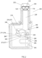
- the assembly 200 comprises a shell 210 for housing components of the handheld assembly.
- Shell 210 may be comprised of two halves (one half is shown) which are injected molded and snap fitted together, for example.
- a plunger 220 is at least partially enclosed within shell 210 and extends from the shell and configured to express the unit dose form 230 containing a medicament 235.
- unit dose form 230 is contained within a dispense tip 232 that is configured to attach to the shell 210.
- unit dose form 230 also contains an internal piercing member 110 which itself includes an internal channel 120.
- a dispense button 240 is at least partially enclosed within shell 210 and extends from the shell and is slidable between the shell halves when acted upon by a user's hand.
- a drive member 250 is located within shell 210 and is in communication with dispense button 240 and in preferred embodiments drive member 250 is comprised of a post or other protrusion attached to or molded as part of dispense button 240.
- a plunger escapement member 260 (hereinafter “escapement”) is also contained within shell 210 and is movable (rotatable and/or translatable) about an axis 265 within shell 210.
- Escapement 260 may be a polygonal body having multiple sides which comprise at least one ramp 270 upon its surface (four ramps 270, 271, 272 and 290 are shown in this example).
- the escapement 260 may be a solid or hollow molded or machined body.
- an escapement shall refer to device or body that provides mechanical linkage between at least one source body to at least one other receiver body. Such devices are used to provide a step wise mechanical action when acted upon by an energy source.
- Each ramp 270 upon its surface has a predetermined profile 275 comprised of a radius of curvature, a linear slope or combination of the two in one or more sections upon the surface.
- Each ramp 270 is configured to provide a defined action when drive member 250 translates along its surface, to be described below in greater detail.
- Assembly 200 may also include a plunger escapement member return spring 280; a plunger hold surface 285; a reset ramp surface 290; a dispense button return spring 292 at the base dispense button 240, and a plunger return spring 295 all of which are to be described in detail below.
- the assembly as shown in FIG 2 is in its initial stage characterized as "ready to load” meaning plunger 220 is in a retracted and able to accept dispense tip 232 with unit dose 230.
- Dispense button 240 is also in a retracted state meaning it is substantially withdrawn within shell 210. Escapement 260 is in its initial static position as well.
- first ramp's 270 predetermined profile 275 is a single section with a constant slope, though other profiles may be contemplated.
- second ramp 271 though comprising a single side or face of escapement 260, has two ramp sections ( 271 and 272) of varying profile (276 and 277, respectively) whereby a first section 271 has an initial curvature or radius, followed by a second section 272 of a substantially flat or linear slope.
- escapement 260 As escapement 260 is acted upon by translating drive member 250, it (escapement 260 ) rotates around an axis 265 (not shown behind escapement body), moving it out of the way of the drive member 250.
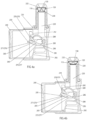
- FIG 3B shows dispense button 240 extended and drive member 250 at left edge of escapement 260. Once dispense button 240 is fully extended and drive member 250 is clear of escapement 260, as shown in FIG 3C , escapement spring 295 will move the escapement 260 back to its position, thus placing the assembly in a make ready state.
- dispense button 240 is depressed into shell 210 which causes drive member 250 to travel back towards escapement 260 until it engages with a second ramp 271 on the escapement's underside (in this embodiment) with a separate predetermined profile 276.
- drive member 250 translates along second ramp 271 which causes escapement 260 to make contact with and extending plunger 220 compressing unit dose 230.
- drive member 250 continues to translate along the second ramp 271 during the dispense activation until it reaches the end of the second ramp while plunger 220 continues to compress unit dose 230 and dispensing medicament 235.
- plunger return spring 295 engages with shell 210.
- drive member 250 engages with plunger hold surface 285 near the base of plunger 220 as shown in FIG 6 .
- Plunger hold surface 285 serves as stopping point in the dispense which allows drive member 250 to hold the plunger in an extended position until dispense button 240 is released.
- dispense button 240 is released by the user, and one or more dispense button return springs 292 will push dispense button 240 outward from shell 210 causing drive member 250 to press out on reset surface 290 located on the end of escapement 260 as shown in FIG 7 .
- the reset surface 290 comprises a fourth ramp on escapement 260, which acts as turning point for drive member 250 to reverse direction.
- escapement 260 may move in a translational motion along axis 266 (depicted by arrows) in a vertical direction when acted upon by plunger return spring 295.
- Escapement 260 will move along this second axis 266 until there is enough space between the second ramp 270 on the escapement and the plunger hold surface 285 for drive member 250 to pass between the two bodies as shown in FIG 8 .
- plunger 220 driven by plunger return spring 295, will retract back to its static position and escapement 260 will return to initial state (i.e. "return" stage) position once reset surface 290 has been cleared.
- initial state i.e. "return” stage
- plunger return spring 295 may be comprised of a partial loop attached to a surface within inner shell 210 body, and in other embodiments it may be attached to dispense button 240. It may be molded as a single part or attached or welded as a separate part and may be comprised of the same or different material.
- the dispense button return spring 292 may be provided as a feature molded together with the dispense button 240 and typically comprised of a curved surface capable of bending and thus storing energy as a spring.
- certain embodiments of the assembly may include a plunger escapement return spring 280.
- this spring acts to pull back or reverse plunger 220. This action is beneficial for avoiding or reducing cross contamination among unit dose forms, particularly between those dispensed and those awaiting dispense in a multi-dose embodiment.
- a dispensed unit dose form has a tendency for surface tension and other charge effects to cause a droplet of the medicament material to remain at the tip; typically partially within and outside the internal channel 120 of the internal piercing member 110 once it has punctured the unit dose 230 lidstock.
- the unit dose form 230 is typically comprised of metal and polymer laminates which while crushable, retain some elasticity under deformation.
- spring 280 draws back plunger 220 following dispense, the unit dose form 230 elastically expands, drawing inward the adhering droplet of medicament where it largely remains, dries and is thus unable to transfer to other unit doses or other surfaces of the dispense assembly.
- assembly 200 may be configured for single use whereby escapement 260 is comprised of a single ramp 270 for dispense or include two ramps one for "make ready" ( 270 ) and one for dispense ( 271 ).
- dispense button 240 may originate in extended form and thus already configured ready to dispense, or non-extended and thus for compactness retractable for "make ready" staging prior to dispense. In both these single-use embodiments, the dispense button following dispense may be pressable back into the housing following dispense, again for compactness, without cycling the device components for another dose.
- plunger escapement member 260 may pivot at one or more different axes points as shown for example in FIGs 10A and 10B .
- axis 265 is located away from the main body of escapement 260 whereby a pin may translate within a slotted portion of the base of plunger escapement return spring 280.
- FIG 10A as dispense button 240 is withdrawn during the early portion of the make ready stage, drive member 250 moves along ramp surface 270 and escapement 260 pivots downward about axis 265 located to the rear (in the right in the figure) of the escapement.
- FIG 10B depicts drive member 250 near the end of ramp 270 with escapement 260 rotated downward, dispense button 240 fully withdrawn and the assembly in a make ready state.
- assembly 200 may further comprise a removable dispense tip as shown in FIG 11 .
- Dispense tip 232 includes a unit dose form 230 (not shown) containing a medicament 235 (not shown) as in previous embodiments.
- unit dose form 230 includes an internal piercing member 110 with an internal channel 120.
- the unit dose is preloaded in the distal end 310 of a dispense tip 232 which in this embodiment has a cylindrical hollow body 340 along its axis.
- the distal end 310 may be domed or other shape configured to receive and interact with unit dose 230 and has a thru hole 350 from which the medicament is dispensed to a subject.
- One or more splines 360 may be located upon an upper surface of shell 210 and proximate and at least partially circumferential to the opening in shell 210 for plunger 220.
- Splines 360 may be semi-circular with a radius similar to that as the plunger 220 opening and are configured to rotatably interlock with one or more tabs 370 located at the lower end of body 320 of dispense tip 232.
- the tabs 370 and splines 360 thus provide for the ability to removably affix the dispense tip to the shell for reloadable operation.
- the dispense tip 232 may be configured in strips 410 comprising a linear array of more than one preloaded dispense tip 232.
- dispense tip 232 tabs 370 are replaced by two oppositely located continuous lips 420 configured to slide though splines 360.
- the strip may be manually loaded and advanced by a user without additional mechanisms for simplicity and cost effectiveness.
- Lip(s) 420 may also include indentations 440 along their lengths which interact with protrusion points 450 within splines 360 to provide a click sensation as the strip is being advanced to indicate to the user the correct lateral position of next dispense tip.
- a loadable multi-dose array is provided with a loadable multi-dose array.
- more than one dispense tip may thus be inexpensively molded together as a single unit and provided in a number to a user according to a particular dosing schedule.
- the strip 410 may also include separation points 430 in between individual dispense tips to facilitate separation of longer arrays into prescribed numbers, and/or detachment of dispensed doses by a user.
Landscapes
- Health & Medical Sciences (AREA)
- Engineering & Computer Science (AREA)
- Animal Behavior & Ethology (AREA)
- Anesthesiology (AREA)
- Biomedical Technology (AREA)
- Heart & Thoracic Surgery (AREA)
- Hematology (AREA)
- Life Sciences & Earth Sciences (AREA)
- General Health & Medical Sciences (AREA)
- Public Health (AREA)
- Veterinary Medicine (AREA)
- Pulmonology (AREA)
- Bioinformatics & Cheminformatics (AREA)
- Mechanical Engineering (AREA)
- Infusion, Injection, And Reservoir Apparatuses (AREA)
Description
- Embodiments of the subject matter disclosed herein generally relate to medical devices and systems for administering medicaments to a subject; more particularly, hand operated devices and systems for dispensing a unit dose form containing a medicament to a subject.
- Certain diseases and medical conditions that are systemic, neurological or local are treatable via the administration of drugs and therapeutic agents taken topically or systemically through the eye, ear, mouth, nose, lungs or dermal skin layer. A number of pharmaceutical or biologic agents are deliverable as liquids, suspensions, emulsions, powders or particles orally to the lungs, sublingual, buccal or intra-nasally (including nose to brain), and may be administered for topical, systemic or intracranial deposition, including but not limited to antibiotics, antipyretics, anti-inflammatories, beta-blockers, biologies, biosimilars, cannabinoids, vitamins, botanicals, co-factors, enzymes, inhibitors, activators, nutrients, vaccines including DNA based killed or live virus or microorganisms, nucleic acids, proteins, peptides, antibodies, peptide mimetics, prophylactic or therapeutic immune-modulators, anti-viral and anti-bacterial compounds, biologies, diagnostic agents and other agents, pharmaceutical compositions or medicaments.
- Hand operated devices (either as single use or multi-use devices) have been developed to deliver dose quantities where each expression by hand of the device delivers an individual dose. For example,
Fuchs et al. U.S. Patent 6,708,846 teaches a reusable dispenser unit and a media container for a medicament for intranasal administration. The device has a release button and a compressed spring that pushes against a rod and discharges the drug.Ritsche et al. U.S. Patent 6,725,857 claims a multi-dose strip of blisters sequentially expressed by a device with a spring-loaded firing button attached to a pretensioned storage element that rotates a conveying drum.Sullivan et al. U.S. Patent 8,377,009 discloses handheld devices with a sliding mechanism and an angled cam attached to a firing button which activates a plunger for discharging a crushable unit dose ampule or blister. -
US2013158474A1 discloses intranasal delivery devices include dosage forms containing medical compositions for use in the intranasal devices, and methods of delivering medical compositions to the nasal mucosa of users. The devices dispense a predetermined quantity of fluid into the nasal passage of a user, in which the predetermined quantity of fluid is contained in, or produced in a dosage form or blister that is crushed by a plunger with sufficient force to drive the dosage form against a piercing mechanism, piercing the dosage form and forcing the liquid contents from the dosage form and through a delivery channel into a spray to be directed into the nasal passage of a user. The plunger is connected to a trigger device by a linkage that confers a mechanical advantage to the trigger mechanism. -
DE102012106438A1 discloses a disposable dosing device for nasal spray or drop applications with a bearing element and a dispensing element, the bearing element being detachably connected to the dispensing element. -
US2010331765A1 discloses delivery systems configurable to administer either single-dose or multiple-doses of one or more substances to a user, for example to the eye, nose, mouth, ear or rectum of the user. The precise and repeatable dosing features of the presently disclosed delivery systems overcome many of the disadvantages associated with known methods for dispensing substances to, for example, the eye of a user. The delivery systems administer precise doses of a substance to a precise location from unit dosage forms that may be single-dose or multiple-dose unit dosage forms, which may be externally or internally pierced. -
US7726519B2 discloses a fluid dispenser device, comprising: a dispenser orifice (5); a reservoir (10) containing at least one dose of fluid; at least one piston (15) axially slidable in said reservoir (10) so as to dispense said fluid; a dispenser member (20) co-operating with said piston (15); and an actuator element (30) co-operating with said dispenser member (20); said device being characterized in that said dispenser member (20) is displaceable between a blocking position, preventing said actuator element (30) from being actuated, and a release position in which the actuation of said actuator element (30) displaces said dispenser member (20) so as to dispense a dose of fluid, said dispenser member (20) being displaced manually from its blocking position to its release position before said device is actuated. -
US2008210228A1 discloses a sprayer device utilising a friction held piston that fires automatically upon full depression of the firing cap. The drive spring does not release to fire the piston until after the spring is fully compressed because the force required to overcome the frictional force between said high friction engaging surface of the piston and the piston shaft is greater than the force required to compress said spring. A user may procure a monodose of medicine by (i) unlocking a child resistant locking mechanism; (ii) applying compressive force against the firing cap so as to first compress the spring and then to push the piston out of an piston engaging friction area such that the spring causes the distal end of the piston to break the medicine container to drive medicine through the spray nozzle in a manner that is user independent as to dosage amount and dosage speed of delivery. -
US2007131717A1 discloses a fluid dispensing device for dispensing a fluid form medicament formulation having a viscosity of from 10 to 2000 mPa.s. and comprises a housing and a fluid discharge device. The fluid discharge device is arranged to be actuated by one or more levers so as to apply a force to the fluid discharge device which is used to move a container forming part of the fluid discharge device along a longitudinal axis of the fluid discharge device to cause actuation of a pump forming part of the fluid discharge device. A pre-load means is used to prevent actuation of the pump until a pre-determined force is applied to each lever of sufficient magnitude to guarantee the production of a well developed efficient spray from the fluid dispensing device. -
EP1084763A2 discloses a dispenser (11) for the delivery of atomized liquid medium from a container by a sequence of manual operations which deliver small amounts of the liquid medium, with a switch-over motion between two successive such operations, where the switch-over motion takes place automatically after each operation. -
DE19905993A1 discloses a dispenser (11) comprising a container (12) for media to be dispensed, an outlet opening (19), outlet channels with opening and closure elements (15, 16) between the outlet opening and the container, and a separable and re-usable operating unit whose functional elements at least support operation of the dispenser. - The invention is defined in independent claim 1. Preferred embodiments of the invention are defined in the dependent claims. According to an embodiment, there is a handheld assembly for dispensing a medicament to a subject. The assembly includes a unit dose form containing a medicament; a shell; a plunger; a dispense button; a drive member in communication with the dispense button; and a plunger escapement having more than one ramp wherein each ramp has a predetermined profile. A first motion of the dispense button causes the drive member to translate along a first ramp of the plunger escapement member readying the assembly for dispense, a second motion of the dispense button causes the drive member to translate along a second ramp of the plunger escapement member extending the plunger to express the unit dose form.
- According to another embodiment, there is a handheld assembly for dispensing a medicament to a subject. The assembly includes a shell; a dispense button; a plunger; a single plunger escapement member with a plurality of ramp surfaces; and a drive member disposed on the dispense button. A first motion of the dispense button causes the drive member to translate along a plunger escapement member ramp surface and a second motion causes the drive member to translate along a second plunger escapement member ramp surface to cycle the dispense button and the plunger between plural dispense states.
- According to yet another embodiment, there is a handheld assembly for dispensing a medicament to a subject. The assembly includes a shell with more than one exterior surface and housing a dispense button, a plunger, and an escapement having more than one ramp surface; a hollow cylindrically shaped dispense tip body having an outer surface, a domed distal end having a thru hole, a unit dose form containing a medicament positioned within the distal end, and a base end having at least one tab member. A shell surface has one or more splines configured to rotatably interlock with the tabs of the dispense tip to removably affix the dispense tip to the shell.
- The accompanying drawings, which are incorporated in and constitute a part of the specification, illustrate one or more embodiments and, together with the description, explain these embodiments. In the drawings:
-
Figures 1A thru 1E illustrate an exemplary set of stages of dispense. -
Figure 2 shows an exemplary handheld assembly in its initial stage. -
Figures 3A thru 3C show an exemplary handheld assembly during the make ready stage. -
Figures 4A and B show an exemplary handheld assembly during early dispense stage. -
Figure 5 shows an exemplary handheld assembly drive member translating along a second ramp during dispense. -
Figure 6 shows an exemplary handheld assembly drive member engaging a plunger hold surface during dispense. -
Figure 7 shows an exemplary handheld assembly drive member engaging a reset surface during dispense. -
Figure 8 shows an exemplary handheld assembly drive member passing in between the escapement and plunger hold surface during dispense. -
Figure 9 shows an exemplary handheld assembly with its mechanisms returned to their original state following dispense. -
Figure 10A and B show an exemplary handheld assembly with an alternative escapement embodiment. -
Figure 11 shows an exemplary handheld assembly with an interlocking dispense tip. -
Figure 12 shows an exemplary handheld assembly with a strip of interlocking dispense tips. - The following description of the embodiments refers to the accompanying drawings. The same reference numbers in different drawings identify the same or similar elements. The following detailed description does not limit the invention. Instead, the scope of the invention is defined by the appended claims. The following embodiments are discussed, for simplicity, with regard to devices and systems for precisely controlled dose delivery of a medicament to a subject. However, the embodiments discussed herein are not limited to such elements.
- Reference throughout the specification to "one embodiment" or "an embodiment" means that a particular feature, structure or characteristic described in connection with an embodiment is included in at least one embodiment of the subject matter disclosed. Thus, the appearance of the phrases "in one embodiment" or "in an embodiment" in various places throughout the specification is not necessarily referring to the same embodiment.
- The following is a limited list of examples of general classes of medicaments administered through the nasal or oral cavity or topically to the eye, ear or skin as liquids, solutions, suspensions, emulsions, powders or reconstituted powders for a host of indications which can include but not limited to anemia, asthma, bronchitis, rhinitis, flu, cancer, cystic fibrosis, diabetes, inflammation, osteoporosis, hepatitis, arthritis, chronic or acute pain, immunodeficiency disorders, multiple sclerosis, endocrinological disorders, neurodegenerative disorders, ocular disorders, metabolic disorders, man-made or naturally occurring bioterror threats, dermal disorders and wounds, etc. Drug compounds for treating those indications include various adjuvants, calcitonin, erythropoietin, heparin, inhibitors, insulin, interferons, interleukins, hormones, neurotropic agents, growth factors, stimulating factors, vasodilators and constrictors, antibiotics, antipyretics, anti-inflammatories, biologics, probiotics, vitamins, co-factors, enzymes, inhibitors, activators, nutrients, aptamers, thioaptamers, anti-virals, immuno-modulators, diagnostic agents, vaccines including killed or live virus or microorganisms, nucleic acids, proteins, peptides, antibodies, peptide mimetics, micro or nanoparticles. This list is not intended to be exhaustive and in no way is inclusive of all possible conditions and diseases, drugs and compounds, or routes or targets of administration, but rather is to illustrate the breadth of medicaments and other agents and indications employable in the present disclosure and contemplated by the present disclosure. For simplicity, the various agents dispensable by devices and system of the present disclosure will herein be referred to as medicaments which is intended to encompass pharmaceutical and non-pharmaceutical agents.
- Blister-based unit dose forms provide a safe, convenient, sterile, easily stored and transported, and controlled dose platform to deliver those medicaments to a subject via a target route of administration. The devices and assemblies that express the unit dose forms can provide for simplified self-administration by a user or may be administered by a medical professional to a subject. A subject may be a human or non-human animal.
- However, as explained in detail below, the unit dose forms require a simple but precise device in order to provide an accurate, full, efficient (low waste), and repeatable dose to a subject. Thus, it is desirable that the dispensing device perform precisely through each stage of the dose dispense sequence. Moreover, the device should preferably be operable by hand, include single as well as reusable embodiments and thus be capable of delivering sequential precise doses to a subject.
- The unit dose forms of the present disclosure, in preferred embodiments, are crushable blisters. Note herein that said dosage forms are commonly referred to in the art using alternative terms as forms, units, unit dose or unit dosage forms, blisters, blister packs, blister wells, wells, chambered wells, ampoules, primary containers, or similar terminology. The dosage forms described herein generally as "unit dose", "unit dose forms", "wells", "blisters" or "chambered wells", etc. are used interchangeably and are intended to encompass the full scope of known formed receptacles commonly in use for medicament substance storage and delivery.
- The manufacturing processes for forming unit dose forms in a continuous web can include a step of drawing a metal, polymer, or laminated metal-polymer foil or other suitable sheet of material with the appropriate mechanical characteristics to allow hot, warm or cold forming and drawing are known in the art and contemplated herein. In certain embodiments, one or more forming pins can be used to form a primary contour, the contour having a depth of at least 100% and up to 150% of the depth of the final formed recess or well. A second stage involves shaping the primary contour with one or more of the same or additional forming pin(s) to the desired formed recess depth and shape, with a depth that is less than the depth of the primary contour, while substantially maintaining the surface area of the primary contour formed in the first stage. The contour or shape of the blister well can be formed to contain certain shape features, indentations, or be imparted with texture by the forming pins to provide for a means of securing the internal piercing device within the blister well or recess.
- The formed well or recess is then typically loaded aseptically with the predetermined quantity of medicament or other material for administration to a subject and in certain preferred embodiments disclosed herein, an internal piercing device is placed into the formed well. A lidding material (or "lidstock') of the same or similar laminated material as the blister well or other sheeting material is then rolled atop the well and bonded to the well sheeting with adhesives, or by pressure, thermal, ultrasonic or other welding means.
- In certain embodiments, the individual dose forms that can be formed in sheets which are in later manufacturing steps, singulated into individual doses for use in single-use, disposable, non-reloadable devices, or for use in devices which are reloadable with additional unit doses for subsequent dosing of the same or different subject(s). Alternatively, and depending upon the application and indication, the sheets may be formed and cut into rows, arrays, grids or other configurations of blisters suitable for use in multi-dose devices or cartridges to be used in such devices. Numerous commercially available laminated structures can be manufactured using known materials and methods which facilitate the production of variable strength of seal between opposing faces, are known in the art and are readily contemplated by the present disclosure.
- Regardless of the shape, size, or geometric configuration of the unit dose form; in certain embodiments each unit dose contains an internal piercing device member. The internal piercing member can be manufactured by techniques known by those skilled in the art, for example injection molding or machining. The piercing member can be constructed of any material with suitable chemical compatibility and mechanical properties to impart the design strength characteristics examples include ceramic, glass, metal, composites, polymeric plastics etc. In preferred embodiments the internal piercing member may be constructed from polymeric materials to include but not limited to polyethylene (PET), polypropylene, polyetherimide (PEI), polysulfone (PSU), polyaryletherketone (PAEK), polystyrene, or poly ether ether ketone (PEEK), self-reinforced polyphenylene (SRP) or other pharmaceutical or medical grade material or materials.
- In preferred embodiments, the internal piercing members are typically injection molded as single piece components, however in certain other embodiments where particular structural features (to be described in greater detail below) are less amenable to one-piece molding; the piercing members can be assembled from multiple machined, printed and/or molded parts. For example, certain embodiments may entail attaching by press fit, friction fit, snap fit, or threading a machined metal or separately molded elongated tip to a plastic base part. Other combinations of parts, manufacturing methods, materials, and assembly methods are known in art and fully contemplated herein. In preferred embodiments, the elongated tip of the piercing member may contain at least one internal channel which provides a high velocity liquid stream and serves as a nozzle for dispensing a medicament as a liquid spray or dispersed powder. According to other embodiments, the elongated tip may be solid (i.e. no internal channel), but the surface may include striations, ribs, spirals or the like to aid in dispersion of a powder once the elongated tip pierces the lidstock.
- An overview of a set of stages for the dispensation of a medicament utilizing a handheld assembly with a plunger and other components acting upon a unit dose form are shown in
FIGs 1A-E . The initial stage as shown inFIG 1A is typically characterized as the "ready to load" stage, whereby aplunger 220 is first positioned to accept a dispensetip 232 preloaded with aunit dose form 230 containing amedicament 235. The unit dose forms as shown contain an internal piercingmember 110 which in preferred embodiments itself includes aninternal channel 120 for passage of themedicament 235. Once the unit dose is loaded and theplunger 220 is in contact with theunit dose 230 as shown inFIG 1B ; the device is prepared for activation, which may be referred to as "ready to dispense", or "make ready" stage or state. - In the "activation" or "dispense" stage, the plunger is acted upon by other device components, the sequence of which will be described in detail below.
Plunger 220 further extends and begins to pressurize theunit dose form 230 as shown inFIG 1C . In this next stage, as theunit dose form 230 begins to breach the unit dose form'slidding material 130 until it punctures and theinternal channel 120 of the internal piercingmember 110 is now in communication with the exterior. Once punctured, thepressurized medicament 235 within the unit dose enters the internal piercingmember 110internal channel 120. The stage shown inFIG 1D is where theunit dose form 230 is crushed andmedicament 235 exits the unit dose and is dispensed to a subject via the desired route of administration. - Finally, once the medicament is dispensed to a subject, the assembly in certain embodiments may be undergo one or more steps in order to be returned to its original state ready for another dispense. This stage will be referred to as the "return" stage and is shown in
FIG 1E . - There are several key dispense characteristics impacted by the design of the device components, particularly the plunger action which generates the internal pressurization and expression of the contents out of the unit dose form. Those performance characteristics include, for example, the dispense efficiency, defined as the fraction of the dose actually dispensed; the characteristics of the dispense spray (droplet size, droplet distribution, spray pattern, plume geometry etc.); the degree of cross contamination between unit dose forms occurring as a result of holdover medicament remaining within or upon the unit dose form following dispense; as well as the convenience and ease of a user's experience with the device, among other aspects.
- An exemplary handheld assembly for administering a medicament to a subject is shown in
FIG 2 . Theassembly 200 comprises ashell 210 for housing components of the handheld assembly.Shell 210 may be comprised of two halves (one half is shown) which are injected molded and snap fitted together, for example. Aplunger 220 is at least partially enclosed withinshell 210 and extends from the shell and configured to express theunit dose form 230 containing amedicament 235. In preferred embodiments,unit dose form 230 is contained within a dispensetip 232 that is configured to attach to theshell 210. Also, in preferred embodiments,unit dose form 230 also contains an internal piercingmember 110 which itself includes aninternal channel 120. - A dispense
button 240 is at least partially enclosed withinshell 210 and extends from the shell and is slidable between the shell halves when acted upon by a user's hand. Adrive member 250 is located withinshell 210 and is in communication with dispensebutton 240 and in preferred embodiments drivemember 250 is comprised of a post or other protrusion attached to or molded as part of dispensebutton 240. - A plunger escapement member 260 (hereinafter "escapement") is also contained within
shell 210 and is movable (rotatable and/or translatable) about anaxis 265 withinshell 210.Escapement 260 may be a polygonal body having multiple sides which comprise at least one ramp 270 upon its surface (fourramps escapement 260 may be a solid or hollow molded or machined body. In the context of the present disclosure, an escapement shall refer to device or body that provides mechanical linkage between at least one source body to at least one other receiver body. Such devices are used to provide a step wise mechanical action when acted upon by an energy source. Each ramp 270 upon its surface has a predetermined profile 275 comprised of a radius of curvature, a linear slope or combination of the two in one or more sections upon the surface. Each ramp 270 is configured to provide a defined action whendrive member 250 translates along its surface, to be described below in greater detail. -
Assembly 200 may also include a plunger escapementmember return spring 280; aplunger hold surface 285; areset ramp surface 290; a dispensebutton return spring 292 at the base dispensebutton 240, and aplunger return spring 295 all of which are to be described in detail below. - The assembly as shown in
FIG 2 is in its initial stage characterized as "ready to load" meaningplunger 220 is in a retracted and able to accept dispensetip 232 withunit dose 230. Dispensebutton 240 is also in a retracted state meaning it is substantially withdrawn withinshell 210.Escapement 260 is in its initial static position as well. - In the "make ready" stage as shown in
FIGs 3A-C , dispensebutton 240 is extended, i.e. withdrawn fromshell 210 which causesdrive member 250 to make contact with (Fig 3A ) and then translate along a first ramp 270 on the upper surface ofescapement 260. In an exemplary embodiment, first ramp's 270 predetermined profile 275 is a single section with a constant slope, though other profiles may be contemplated. For example, as shown in the figures,second ramp 271, though comprising a single side or face ofescapement 260, has two ramp sections (271 and 272) of varying profile (276 and 277, respectively) whereby afirst section 271 has an initial curvature or radius, followed by asecond section 272 of a substantially flat or linear slope. - As
escapement 260 is acted upon by translatingdrive member 250, it (escapement 260) rotates around an axis 265 (not shown behind escapement body), moving it out of the way of thedrive member 250.FIG 3B shows dispensebutton 240 extended and drivemember 250 at left edge ofescapement 260. Once dispensebutton 240 is fully extended and drivemember 250 is clear ofescapement 260, as shown inFIG 3C ,escapement spring 295 will move theescapement 260 back to its position, thus placing the assembly in a make ready state. - At the beginning of the dispense activation stage, as shown in exemplary
FIG 4A , dispensebutton 240 is depressed intoshell 210 which causesdrive member 250 to travel back towardsescapement 260 until it engages with asecond ramp 271 on the escapement's underside (in this embodiment) with a separatepredetermined profile 276. As dispensebutton 240 is continued to be depressed, as shown inFIG 4B ,drive member 250 translates alongsecond ramp 271 which causesescapement 260 to make contact with and extendingplunger 220compressing unit dose 230. - As shown in
FIG 5 ,drive member 250 continues to translate along thesecond ramp 271 during the dispense activation until it reaches the end of the second ramp whileplunger 220 continues to compressunit dose 230 and dispensingmedicament 235. Prior to drivemember 250 reaching the end of second ramp 270,plunger return spring 295 engages withshell 210. Optionally, whendrive member 250 reaches the end of second ramp 270,drive member 250 engages withplunger hold surface 285 near the base ofplunger 220 as shown inFIG 6 .Plunger hold surface 285 serves as stopping point in the dispense which allowsdrive member 250 to hold the plunger in an extended position until dispensebutton 240 is released. - In certain preferred embodiments, at the end of the dispense stage, dispense
button 240 is released by the user, and one or more dispense button return springs 292 will push dispensebutton 240 outward fromshell 210 causingdrive member 250 to press out onreset surface 290 located on the end ofescapement 260 as shown inFIG 7 . In this embodiment, thereset surface 290 comprises a fourth ramp onescapement 260, which acts as turning point fordrive member 250 to reverse direction. In this embodiment,escapement 260 may move in a translational motion along axis 266 (depicted by arrows) in a vertical direction when acted upon byplunger return spring 295. -
Escapement 260 will move along thissecond axis 266 until there is enough space between the second ramp 270 on the escapement and theplunger hold surface 285 fordrive member 250 to pass between the two bodies as shown inFIG 8 . When this occurs,plunger 220, driven byplunger return spring 295, will retract back to its static position andescapement 260 will return to initial state (i.e. "return" stage) position oncereset surface 290 has been cleared. At this point thedispenser assembly 200 has returned with all of the mechanisms in their original state prepared for a subsequent cycle of dispense (FIG 9 ). - As shown in the figures,
plunger return spring 295 may be comprised of a partial loop attached to a surface withininner shell 210 body, and in other embodiments it may be attached to dispensebutton 240. It may be molded as a single part or attached or welded as a separate part and may be comprised of the same or different material. - Similarly, as shown for example in
FIG 7 , the dispensebutton return spring 292 may be provided as a feature molded together with the dispensebutton 240 and typically comprised of a curved surface capable of bending and thus storing energy as a spring. - Also as shown, for example, in
FIG 5 , certain embodiments of the assembly may include a plungerescapement return spring 280. At the end of the dispense, once dispensebutton 240 is released, this spring acts to pull back orreverse plunger 220. This action is beneficial for avoiding or reducing cross contamination among unit dose forms, particularly between those dispensed and those awaiting dispense in a multi-dose embodiment. A dispensed unit dose form has a tendency for surface tension and other charge effects to cause a droplet of the medicament material to remain at the tip; typically partially within and outside theinternal channel 120 of the internal piercingmember 110 once it has punctured theunit dose 230 lidstock. As discussed earlier, theunit dose form 230 is typically comprised of metal and polymer laminates which while crushable, retain some elasticity under deformation. Whenspring 280 draws backplunger 220 following dispense, theunit dose form 230 elastically expands, drawing inward the adhering droplet of medicament where it largely remains, dries and is thus unable to transfer to other unit doses or other surfaces of the dispense assembly. - Other embodiments are readily contemplated by the disclosure herein. For example,
assembly 200 may be configured for single use wherebyescapement 260 is comprised of a single ramp 270 for dispense or include two ramps one for "make ready" (270) and one for dispense (271). In this embodiment, dispensebutton 240 may originate in extended form and thus already configured ready to dispense, or non-extended and thus for compactness retractable for "make ready" staging prior to dispense. In both these single-use embodiments, the dispense button following dispense may be pressable back into the housing following dispense, again for compactness, without cycling the device components for another dose. - In yet other embodiments,
plunger escapement member 260 may pivot at one or more different axes points as shown for example inFIGs 10A and 10B . Here,axis 265 is located away from the main body ofescapement 260 whereby a pin may translate within a slotted portion of the base of plungerescapement return spring 280. As shown inFIG 10A , as dispensebutton 240 is withdrawn during the early portion of the make ready stage,drive member 250 moves along ramp surface 270 andescapement 260 pivots downward aboutaxis 265 located to the rear (in the right in the figure) of the escapement.FIG 10B depictsdrive member 250 near the end of ramp 270 withescapement 260 rotated downward, dispensebutton 240 fully withdrawn and the assembly in a make ready state. - In multi-use, reusable embodiments,
assembly 200 may further comprise a removable dispense tip as shown inFIG 11 . Dispensetip 232 includes a unit dose form 230 (not shown) containing a medicament 235 (not shown) as in previous embodiments. In preferred embodiments,unit dose form 230 includes an internal piercingmember 110 with aninternal channel 120. The unit dose is preloaded in thedistal end 310 of a dispensetip 232 which in this embodiment has a cylindricalhollow body 340 along its axis. Thedistal end 310 may be domed or other shape configured to receive and interact withunit dose 230 and has a thruhole 350 from which the medicament is dispensed to a subject. - One or
more splines 360 may be located upon an upper surface ofshell 210 and proximate and at least partially circumferential to the opening inshell 210 forplunger 220.Splines 360 may be semi-circular with a radius similar to that as theplunger 220 opening and are configured to rotatably interlock with one ormore tabs 370 located at the lower end ofbody 320 of dispensetip 232. Thetabs 370 andsplines 360 thus provide for the ability to removably affix the dispense tip to the shell for reloadable operation. - In yet other embodiments, for example as shown in
FIG 12 , the dispensetip 232 may be configured instrips 410 comprising a linear array of more than one preloaded dispensetip 232. In this embodiment, dispensetip 232tabs 370 are replaced by two oppositely locatedcontinuous lips 420 configured to slide thoughsplines 360. The strip may be manually loaded and advanced by a user without additional mechanisms for simplicity and cost effectiveness. Lip(s) 420 may also includeindentations 440 along their lengths which interact withprotrusion points 450 withinsplines 360 to provide a click sensation as the strip is being advanced to indicate to the user the correct lateral position of next dispense tip. - Thus, in this embodiment with a reusable handheld dispensing assembly with a cycling plunger is provided with a loadable multi-dose array. Further, more than one dispense tip may thus be inexpensively molded together as a single unit and provided in a number to a user according to a particular dosing schedule. The
strip 410 may also includeseparation points 430 in between individual dispense tips to facilitate separation of longer arrays into prescribed numbers, and/or detachment of dispensed doses by a user.
Claims (12)
- A handheld assembly (200) for dispensing a medicament (235) to a subject, the assembly comprising:a unit dose form, the unit dose form containing a medicament and an internal piercing member;a shell (210)ieconfigured for housing components of the handheld assembly;a plunger (220) at least partially enclosed within the shell and extending from the shell and configured to express the unit dose form; adispense button (240) at least partially enclosed within the shell and extending from the shell and in slidable communication with the shell; adrive member (250) located within the shell and in communication with the dispense button; aplunger escapement member (260) movable about an axis (265) within the shell and having more than one ramp (270) wherein each ramp has a predetermined profile (275)wherein a first motion of the dispense button causes the drive member to translate along a first ramp of the plunger escapement member readying the assembly for dispense, andwherein a second motion of the dispense button causes the drive member to translate along a second ramp of the plunger escapement member extending the plunger to express the unit dose form.
- The assembly of Claim 1, wherein the drive member is comprised of a protruding body integral with or attached to the dispense button.
- The assembly of Claim 1
further comprising a plunger escapement member return spring disposed within the shell. - The assembly of Claim 1,
further comprising a dispense button return spring disposed within the shell. - The assembly of Claim 1,
wherein the number of plunger escapement member ramps is two and the first and second ramps are each disposed on different sides of the plunger escapement member. - The assembly of Claim 1,
wherein the plunger escapement member further comprises at least three ramps of which one is configured as a reset ramp to return the assembly to an original static position. - The assembly of Claim 1,
wherein at least one of the ramps of the plunger escapement member has a predetermined profile with more than one discrete section. - The assembly of Claim 1,
wherein the internal piercing member further comprises an internal channel. - The assembly (200) of claim 1, further comprising a dispense tip (232) having a hollow cylindrically shaped body (340) with an outer surface, a domed distal end (310) having a thru hole (350), a unit dose form (230) containing a medicament positioned within the distal end, and a base end (320) having at least one tab member (370);wherein a shell surface proximate the plunger comprises one or more splines (360) configured to rotatably interlock with the tabs of the dispense tip to removably affix the dispense tip to the shell; andwherein the dispense tip affixed to the shell surface is configured to accept the plunger to express the unit dose form.
- The assembly of Claim 9,
wherein the dispense tip is further comprised as a multi-dose array. - The assembly of Claim 9,
wherein the plunger hold surface is configured to hold the plunger in an extended position until the dispense button is released. - The assembly of Claim 9,
wherein a first motion of the dispense button causes the drive member to translate along a first escapement member ramp surface and a second motion causes the drive member to translate along a second escapement member ramp surface to cycle the dispense button and the plunger between plural dispense states.
Applications Claiming Priority (3)
| Application Number | Priority Date | Filing Date | Title |
|---|---|---|---|
| US201962824788P | 2019-03-27 | 2019-03-27 | |
| US201962948777P | 2019-12-16 | 2019-12-16 | |
| PCT/US2020/025076 WO2020198536A1 (en) | 2019-03-27 | 2020-03-26 | Hand operated devices for administration of a medicament |
Publications (3)
| Publication Number | Publication Date |
|---|---|
| EP3946526A1 EP3946526A1 (en) | 2022-02-09 |
| EP3946526A4 EP3946526A4 (en) | 2022-12-28 |
| EP3946526B1 true EP3946526B1 (en) | 2024-09-04 |
Family
ID=72610108
Family Applications (1)
| Application Number | Title | Priority Date | Filing Date |
|---|---|---|---|
| EP20778981.9A Active EP3946526B1 (en) | 2019-03-27 | 2020-03-26 | Hand operated devices for administration of a medicament |
Country Status (4)
| Country | Link |
|---|---|
| US (1) | US20220152319A1 (en) |
| EP (1) | EP3946526B1 (en) |
| CA (1) | CA3135169A1 (en) |
| WO (1) | WO2020198536A1 (en) |
Family Cites Families (14)
| Publication number | Priority date | Publication date | Assignee | Title |
|---|---|---|---|---|
| DE4412041A1 (en) * | 1994-04-08 | 1995-10-12 | Pfeiffer Erich Gmbh & Co Kg | Discharge device for flowable media, in particular for discharge in just one stroke |
| EP1071517B1 (en) | 1999-02-14 | 2008-04-02 | Ing. Erich Pfeiffer GmbH | Dispenser for flowable media |
| DE19905993A1 (en) | 1999-02-14 | 2000-08-17 | Pfeiffer Erich Gmbh & Co Kg | Dispenser of flowable media comprises a container for media, an outlet opening, connecting channels with opening and closure elements, and a separable and re-usable operating unit |
| DE19944209A1 (en) * | 1999-09-15 | 2001-03-22 | Pfeiffer Erich Gmbh & Co Kg | Dispenser for possibly atomizing the discharge of a medium, in particular a liquid, from a container |
| DE10011120A1 (en) * | 2000-03-09 | 2001-09-13 | Pfeiffer Erich Gmbh & Co Kg | Media Donor |
| GB0109002D0 (en) * | 2001-04-10 | 2001-05-30 | Glaxo Group Ltd | Dispenser |
| FR2847889B1 (en) * | 2002-11-29 | 2005-03-04 | DEVICE FOR DISPENSING FLUID PRODUCT | |
| CN1901958B (en) | 2003-11-03 | 2011-03-09 | 葛兰素集团有限公司 | Fluid distribution device |
| US7219664B2 (en) * | 2005-04-28 | 2007-05-22 | Kos Life Sciences, Inc. | Breath actuated inhaler |
| BRPI0806474A2 (en) * | 2007-01-09 | 2011-09-27 | Mystic Pharmaceuticals Inc | intranasal cartridge devices |
| US20080210228A1 (en) | 2007-03-02 | 2008-09-04 | Corbco, Inc. | Monodose nasal sprayer |
| US8579856B2 (en) | 2007-05-16 | 2013-11-12 | Mystic Pharmaceuticals, Inc. | Unit dose drug delivery platform |
| GB201117518D0 (en) * | 2011-10-11 | 2011-11-23 | Consort Medical Plc | Fluid delivery device |
| DE102012106438A1 (en) * | 2011-11-04 | 2013-05-08 | Karl-Heinz Fuchs | Einwegdosierer |
-
2020
- 2020-03-26 CA CA3135169A patent/CA3135169A1/en active Pending
- 2020-03-26 US US17/436,236 patent/US20220152319A1/en active Pending
- 2020-03-26 EP EP20778981.9A patent/EP3946526B1/en active Active
- 2020-03-26 WO PCT/US2020/025076 patent/WO2020198536A1/en not_active Ceased
Also Published As
| Publication number | Publication date |
|---|---|
| EP3946526A4 (en) | 2022-12-28 |
| CA3135169A1 (en) | 2020-10-01 |
| US20220152319A1 (en) | 2022-05-19 |
| EP3946526A1 (en) | 2022-02-09 |
| WO2020198536A1 (en) | 2020-10-01 |
Similar Documents
| Publication | Publication Date | Title |
|---|---|---|
| US12329949B2 (en) | Cartridge devices for administration of a medicament | |
| US9446197B2 (en) | Intranasal cartridge devices | |
| EP2231236B1 (en) | Atomizing device, inhaler for dispensing a liquid formulation | |
| US11547807B2 (en) | Delivery device | |
| EP2164799B1 (en) | Combination unit dose dispensing containers | |
| US8834411B2 (en) | Medical devices for dispensing powders | |
| CN114007674A (en) | Portable inhaler | |
| US20080210228A1 (en) | Monodose nasal sprayer | |
| CN113573819A (en) | Piston, cylinder, distributor | |
| US20220152319A1 (en) | Hand operated devices for administration of a medicament | |
| EP3352824B1 (en) | Dry powder unit dose device and delivery system | |
| CN118613296A (en) | Fluid distribution device and mechanical energy storage device | |
| CN118647424A (en) | Fluid dispensing device |
Legal Events
| Date | Code | Title | Description |
|---|---|---|---|
| STAA | Information on the status of an ep patent application or granted ep patent |
Free format text: STATUS: THE INTERNATIONAL PUBLICATION HAS BEEN MADE |
|
| PUAI | Public reference made under article 153(3) epc to a published international application that has entered the european phase |
Free format text: ORIGINAL CODE: 0009012 |
|
| STAA | Information on the status of an ep patent application or granted ep patent |
Free format text: STATUS: REQUEST FOR EXAMINATION WAS MADE |
|
| 17P | Request for examination filed |
Effective date: 20211001 |
|
| AK | Designated contracting states |
Kind code of ref document: A1 Designated state(s): AL AT BE BG CH CY CZ DE DK EE ES FI FR GB GR HR HU IE IS IT LI LT LU LV MC MK MT NL NO PL PT RO RS SE SI SK SM TR |
|
| DAV | Request for validation of the european patent (deleted) | ||
| DAX | Request for extension of the european patent (deleted) | ||
| A4 | Supplementary search report drawn up and despatched |
Effective date: 20221124 |
|
| RIC1 | Information provided on ipc code assigned before grant |
Ipc: A61M 11/00 20060101ALI20221118BHEP Ipc: B05B 11/04 20060101ALI20221118BHEP Ipc: B05B 11/02 20060101ALI20221118BHEP Ipc: B05B 11/00 20060101ALI20221118BHEP Ipc: A61M 15/08 20060101ALI20221118BHEP Ipc: A61M 15/00 20060101ALI20221118BHEP Ipc: A61M 11/06 20060101AFI20221118BHEP |
|
| GRAP | Despatch of communication of intention to grant a patent |
Free format text: ORIGINAL CODE: EPIDOSNIGR1 |
|
| STAA | Information on the status of an ep patent application or granted ep patent |
Free format text: STATUS: GRANT OF PATENT IS INTENDED |
|
| INTG | Intention to grant announced |
Effective date: 20240327 |
|
| GRAS | Grant fee paid |
Free format text: ORIGINAL CODE: EPIDOSNIGR3 |
|
| GRAA | (expected) grant |
Free format text: ORIGINAL CODE: 0009210 |
|
| STAA | Information on the status of an ep patent application or granted ep patent |
Free format text: STATUS: THE PATENT HAS BEEN GRANTED |
|
| AK | Designated contracting states |
Kind code of ref document: B1 Designated state(s): AL AT BE BG CH CY CZ DE DK EE ES FI FR GB GR HR HU IE IS IT LI LT LU LV MC MK MT NL NO PL PT RO RS SE SI SK SM TR |
|
| REG | Reference to a national code |
Ref country code: GB Ref legal event code: FG4D |
|
| REG | Reference to a national code |
Ref country code: CH Ref legal event code: EP |
|
| REG | Reference to a national code |
Ref country code: IE Ref legal event code: FG4D |
|
| REG | Reference to a national code |
Ref country code: DE Ref legal event code: R096 Ref document number: 602020037165 Country of ref document: DE |
|
| REG | Reference to a national code |
Ref country code: LT Ref legal event code: MG9D |
|
| REG | Reference to a national code |
Ref country code: NL Ref legal event code: MP Effective date: 20240904 |
|
| PG25 | Lapsed in a contracting state [announced via postgrant information from national office to epo] |
Ref country code: NO Free format text: LAPSE BECAUSE OF FAILURE TO SUBMIT A TRANSLATION OF THE DESCRIPTION OR TO PAY THE FEE WITHIN THE PRESCRIBED TIME-LIMIT Effective date: 20241204 |
|
| PG25 | Lapsed in a contracting state [announced via postgrant information from national office to epo] |
Ref country code: GR Free format text: LAPSE BECAUSE OF FAILURE TO SUBMIT A TRANSLATION OF THE DESCRIPTION OR TO PAY THE FEE WITHIN THE PRESCRIBED TIME-LIMIT Effective date: 20241205 Ref country code: PL Free format text: LAPSE BECAUSE OF FAILURE TO SUBMIT A TRANSLATION OF THE DESCRIPTION OR TO PAY THE FEE WITHIN THE PRESCRIBED TIME-LIMIT Effective date: 20240904 Ref country code: FI Free format text: LAPSE BECAUSE OF FAILURE TO SUBMIT A TRANSLATION OF THE DESCRIPTION OR TO PAY THE FEE WITHIN THE PRESCRIBED TIME-LIMIT Effective date: 20240904 |
|
| PG25 | Lapsed in a contracting state [announced via postgrant information from national office to epo] |
Ref country code: BG Free format text: LAPSE BECAUSE OF FAILURE TO SUBMIT A TRANSLATION OF THE DESCRIPTION OR TO PAY THE FEE WITHIN THE PRESCRIBED TIME-LIMIT Effective date: 20240904 |
|
| PG25 | Lapsed in a contracting state [announced via postgrant information from national office to epo] |
Ref country code: LV Free format text: LAPSE BECAUSE OF FAILURE TO SUBMIT A TRANSLATION OF THE DESCRIPTION OR TO PAY THE FEE WITHIN THE PRESCRIBED TIME-LIMIT Effective date: 20240904 |
|
| PG25 | Lapsed in a contracting state [announced via postgrant information from national office to epo] |
Ref country code: HR Free format text: LAPSE BECAUSE OF FAILURE TO SUBMIT A TRANSLATION OF THE DESCRIPTION OR TO PAY THE FEE WITHIN THE PRESCRIBED TIME-LIMIT Effective date: 20240904 |
|
| PG25 | Lapsed in a contracting state [announced via postgrant information from national office to epo] |
Ref country code: ES Free format text: LAPSE BECAUSE OF FAILURE TO SUBMIT A TRANSLATION OF THE DESCRIPTION OR TO PAY THE FEE WITHIN THE PRESCRIBED TIME-LIMIT Effective date: 20240904 Ref country code: RS Free format text: LAPSE BECAUSE OF FAILURE TO SUBMIT A TRANSLATION OF THE DESCRIPTION OR TO PAY THE FEE WITHIN THE PRESCRIBED TIME-LIMIT Effective date: 20241204 |
|
| PG25 | Lapsed in a contracting state [announced via postgrant information from national office to epo] |
Ref country code: RS Free format text: LAPSE BECAUSE OF FAILURE TO SUBMIT A TRANSLATION OF THE DESCRIPTION OR TO PAY THE FEE WITHIN THE PRESCRIBED TIME-LIMIT Effective date: 20241204 Ref country code: PL Free format text: LAPSE BECAUSE OF FAILURE TO SUBMIT A TRANSLATION OF THE DESCRIPTION OR TO PAY THE FEE WITHIN THE PRESCRIBED TIME-LIMIT Effective date: 20240904 Ref country code: NO Free format text: LAPSE BECAUSE OF FAILURE TO SUBMIT A TRANSLATION OF THE DESCRIPTION OR TO PAY THE FEE WITHIN THE PRESCRIBED TIME-LIMIT Effective date: 20241204 Ref country code: LV Free format text: LAPSE BECAUSE OF FAILURE TO SUBMIT A TRANSLATION OF THE DESCRIPTION OR TO PAY THE FEE WITHIN THE PRESCRIBED TIME-LIMIT Effective date: 20240904 Ref country code: HR Free format text: LAPSE BECAUSE OF FAILURE TO SUBMIT A TRANSLATION OF THE DESCRIPTION OR TO PAY THE FEE WITHIN THE PRESCRIBED TIME-LIMIT Effective date: 20240904 Ref country code: GR Free format text: LAPSE BECAUSE OF FAILURE TO SUBMIT A TRANSLATION OF THE DESCRIPTION OR TO PAY THE FEE WITHIN THE PRESCRIBED TIME-LIMIT Effective date: 20241205 Ref country code: FI Free format text: LAPSE BECAUSE OF FAILURE TO SUBMIT A TRANSLATION OF THE DESCRIPTION OR TO PAY THE FEE WITHIN THE PRESCRIBED TIME-LIMIT Effective date: 20240904 Ref country code: ES Free format text: LAPSE BECAUSE OF FAILURE TO SUBMIT A TRANSLATION OF THE DESCRIPTION OR TO PAY THE FEE WITHIN THE PRESCRIBED TIME-LIMIT Effective date: 20240904 Ref country code: BG Free format text: LAPSE BECAUSE OF FAILURE TO SUBMIT A TRANSLATION OF THE DESCRIPTION OR TO PAY THE FEE WITHIN THE PRESCRIBED TIME-LIMIT Effective date: 20240904 |
|
| REG | Reference to a national code |
Ref country code: AT Ref legal event code: MK05 Ref document number: 1719712 Country of ref document: AT Kind code of ref document: T Effective date: 20240904 |
|
| PG25 | Lapsed in a contracting state [announced via postgrant information from national office to epo] |
Ref country code: NL Free format text: LAPSE BECAUSE OF FAILURE TO SUBMIT A TRANSLATION OF THE DESCRIPTION OR TO PAY THE FEE WITHIN THE PRESCRIBED TIME-LIMIT Effective date: 20240904 |
|
| PG25 | Lapsed in a contracting state [announced via postgrant information from national office to epo] |
Ref country code: PT Free format text: LAPSE BECAUSE OF FAILURE TO SUBMIT A TRANSLATION OF THE DESCRIPTION OR TO PAY THE FEE WITHIN THE PRESCRIBED TIME-LIMIT Effective date: 20250106 Ref country code: IS Free format text: LAPSE BECAUSE OF FAILURE TO SUBMIT A TRANSLATION OF THE DESCRIPTION OR TO PAY THE FEE WITHIN THE PRESCRIBED TIME-LIMIT Effective date: 20250104 |
|
| PG25 | Lapsed in a contracting state [announced via postgrant information from national office to epo] |
Ref country code: RO Free format text: LAPSE BECAUSE OF FAILURE TO SUBMIT A TRANSLATION OF THE DESCRIPTION OR TO PAY THE FEE WITHIN THE PRESCRIBED TIME-LIMIT Effective date: 20240904 Ref country code: SM Free format text: LAPSE BECAUSE OF FAILURE TO SUBMIT A TRANSLATION OF THE DESCRIPTION OR TO PAY THE FEE WITHIN THE PRESCRIBED TIME-LIMIT Effective date: 20240904 |
|
| PG25 | Lapsed in a contracting state [announced via postgrant information from national office to epo] |
Ref country code: EE Free format text: LAPSE BECAUSE OF FAILURE TO SUBMIT A TRANSLATION OF THE DESCRIPTION OR TO PAY THE FEE WITHIN THE PRESCRIBED TIME-LIMIT Effective date: 20240904 Ref country code: AT Free format text: LAPSE BECAUSE OF FAILURE TO SUBMIT A TRANSLATION OF THE DESCRIPTION OR TO PAY THE FEE WITHIN THE PRESCRIBED TIME-LIMIT Effective date: 20240904 |
|
| PG25 | Lapsed in a contracting state [announced via postgrant information from national office to epo] |
Ref country code: CZ Free format text: LAPSE BECAUSE OF FAILURE TO SUBMIT A TRANSLATION OF THE DESCRIPTION OR TO PAY THE FEE WITHIN THE PRESCRIBED TIME-LIMIT Effective date: 20240904 |
|
| PG25 | Lapsed in a contracting state [announced via postgrant information from national office to epo] |
Ref country code: IT Free format text: LAPSE BECAUSE OF FAILURE TO SUBMIT A TRANSLATION OF THE DESCRIPTION OR TO PAY THE FEE WITHIN THE PRESCRIBED TIME-LIMIT Effective date: 20240904 Ref country code: SK Free format text: LAPSE BECAUSE OF FAILURE TO SUBMIT A TRANSLATION OF THE DESCRIPTION OR TO PAY THE FEE WITHIN THE PRESCRIBED TIME-LIMIT Effective date: 20240904 |
|
| REG | Reference to a national code |
Ref country code: DE Ref legal event code: R097 Ref document number: 602020037165 Country of ref document: DE |
|
| PG25 | Lapsed in a contracting state [announced via postgrant information from national office to epo] |
Ref country code: DK Free format text: LAPSE BECAUSE OF FAILURE TO SUBMIT A TRANSLATION OF THE DESCRIPTION OR TO PAY THE FEE WITHIN THE PRESCRIBED TIME-LIMIT Effective date: 20240904 |
|
| PLBE | No opposition filed within time limit |
Free format text: ORIGINAL CODE: 0009261 |
|
| STAA | Information on the status of an ep patent application or granted ep patent |
Free format text: STATUS: NO OPPOSITION FILED WITHIN TIME LIMIT |
|
| PGFP | Annual fee paid to national office [announced via postgrant information from national office to epo] |
Ref country code: CH Payment date: 20250401 Year of fee payment: 6 |
|
| 26N | No opposition filed |
Effective date: 20250605 |
|
| PG25 | Lapsed in a contracting state [announced via postgrant information from national office to epo] |
Ref country code: SE Free format text: LAPSE BECAUSE OF FAILURE TO SUBMIT A TRANSLATION OF THE DESCRIPTION OR TO PAY THE FEE WITHIN THE PRESCRIBED TIME-LIMIT Effective date: 20240904 |
|
| PG25 | Lapsed in a contracting state [announced via postgrant information from national office to epo] |
Ref country code: MC Free format text: LAPSE BECAUSE OF FAILURE TO SUBMIT A TRANSLATION OF THE DESCRIPTION OR TO PAY THE FEE WITHIN THE PRESCRIBED TIME-LIMIT Effective date: 20240904 |
|
| PG25 | Lapsed in a contracting state [announced via postgrant information from national office to epo] |
Ref country code: LU Free format text: LAPSE BECAUSE OF NON-PAYMENT OF DUE FEES Effective date: 20250326 |
|
| REG | Reference to a national code |
Ref country code: BE Ref legal event code: MM Effective date: 20250331 |
|
| PG25 | Lapsed in a contracting state [announced via postgrant information from national office to epo] |
Ref country code: FR Free format text: LAPSE BECAUSE OF NON-PAYMENT OF DUE FEES Effective date: 20250331 |
|
| PG25 | Lapsed in a contracting state [announced via postgrant information from national office to epo] |
Ref country code: BE Free format text: LAPSE BECAUSE OF NON-PAYMENT OF DUE FEES Effective date: 20250331 |
|
| PG25 | Lapsed in a contracting state [announced via postgrant information from national office to epo] |
Ref country code: IE Free format text: LAPSE BECAUSE OF NON-PAYMENT OF DUE FEES Effective date: 20250326 |
|
| REG | Reference to a national code |
Ref country code: CH Ref legal event code: U11 Free format text: ST27 STATUS EVENT CODE: U-0-0-U10-U11 (AS PROVIDED BY THE NATIONAL OFFICE) Effective date: 20260401 |
|
| PGFP | Annual fee paid to national office [announced via postgrant information from national office to epo] |
Ref country code: GB Payment date: 20260327 Year of fee payment: 7 |
|
| PGFP | Annual fee paid to national office [announced via postgrant information from national office to epo] |
Ref country code: DE Payment date: 20260327 Year of fee payment: 7 |