EP3946115B1 - Elektrochirurgische vorrichtungen mit monopolarer und bipolarer funktionsfähigkeit - Google Patents
Elektrochirurgische vorrichtungen mit monopolarer und bipolarer funktionsfähigkeit Download PDFInfo
- Publication number
- EP3946115B1 EP3946115B1 EP20717285.9A EP20717285A EP3946115B1 EP 3946115 B1 EP3946115 B1 EP 3946115B1 EP 20717285 A EP20717285 A EP 20717285A EP 3946115 B1 EP3946115 B1 EP 3946115B1
- Authority
- EP
- European Patent Office
- Prior art keywords
- electrode
- electrode portion
- tissue
- end effector
- energy
- Prior art date
- Legal status (The legal status is an assumption and is not a legal conclusion. Google has not performed a legal analysis and makes no representation as to the accuracy of the status listed.)
- Active
Links
Images



Classifications
-
- A—HUMAN NECESSITIES
- A61—MEDICAL OR VETERINARY SCIENCE; HYGIENE
- A61B—DIAGNOSIS; SURGERY; IDENTIFICATION
- A61B18/00—Surgical instruments, devices or methods for transferring non-mechanical forms of energy to or from the body
- A61B18/04—Surgical instruments, devices or methods for transferring non-mechanical forms of energy to or from the body by heating
- A61B18/12—Surgical instruments, devices or methods for transferring non-mechanical forms of energy to or from the body by heating by passing a current through the tissue to be heated, e.g. high-frequency current
- A61B18/14—Probes or electrodes therefor
- A61B18/1442—Probes having pivoting end effectors, e.g. forceps
- A61B18/1445—Probes having pivoting end effectors, e.g. forceps at the distal end of a shaft, e.g. forceps or scissors at the end of a rigid rod
-
- A—HUMAN NECESSITIES
- A61—MEDICAL OR VETERINARY SCIENCE; HYGIENE
- A61B—DIAGNOSIS; SURGERY; IDENTIFICATION
- A61B18/00—Surgical instruments, devices or methods for transferring non-mechanical forms of energy to or from the body
- A61B18/04—Surgical instruments, devices or methods for transferring non-mechanical forms of energy to or from the body by heating
- A61B18/12—Surgical instruments, devices or methods for transferring non-mechanical forms of energy to or from the body by heating by passing a current through the tissue to be heated, e.g. high-frequency current
- A61B18/1206—Generators therefor
-
- A—HUMAN NECESSITIES
- A61—MEDICAL OR VETERINARY SCIENCE; HYGIENE
- A61B—DIAGNOSIS; SURGERY; IDENTIFICATION
- A61B18/00—Surgical instruments, devices or methods for transferring non-mechanical forms of energy to or from the body
- A61B2018/00053—Mechanical features of the instrument of device
- A61B2018/00107—Coatings on the energy applicator
- A61B2018/00136—Coatings on the energy applicator with polymer
-
- A—HUMAN NECESSITIES
- A61—MEDICAL OR VETERINARY SCIENCE; HYGIENE
- A61B—DIAGNOSIS; SURGERY; IDENTIFICATION
- A61B18/00—Surgical instruments, devices or methods for transferring non-mechanical forms of energy to or from the body
- A61B2018/00053—Mechanical features of the instrument of device
- A61B2018/00184—Moving parts
- A61B2018/00202—Moving parts rotating
-
- A—HUMAN NECESSITIES
- A61—MEDICAL OR VETERINARY SCIENCE; HYGIENE
- A61B—DIAGNOSIS; SURGERY; IDENTIFICATION
- A61B18/00—Surgical instruments, devices or methods for transferring non-mechanical forms of energy to or from the body
- A61B2018/00571—Surgical instruments, devices or methods for transferring non-mechanical forms of energy to or from the body for achieving a particular surgical effect
- A61B2018/00577—Ablation
-
- A—HUMAN NECESSITIES
- A61—MEDICAL OR VETERINARY SCIENCE; HYGIENE
- A61B—DIAGNOSIS; SURGERY; IDENTIFICATION
- A61B18/00—Surgical instruments, devices or methods for transferring non-mechanical forms of energy to or from the body
- A61B2018/00571—Surgical instruments, devices or methods for transferring non-mechanical forms of energy to or from the body for achieving a particular surgical effect
- A61B2018/00589—Coagulation
-
- A—HUMAN NECESSITIES
- A61—MEDICAL OR VETERINARY SCIENCE; HYGIENE
- A61B—DIAGNOSIS; SURGERY; IDENTIFICATION
- A61B18/00—Surgical instruments, devices or methods for transferring non-mechanical forms of energy to or from the body
- A61B2018/00571—Surgical instruments, devices or methods for transferring non-mechanical forms of energy to or from the body for achieving a particular surgical effect
- A61B2018/00595—Cauterization
-
- A—HUMAN NECESSITIES
- A61—MEDICAL OR VETERINARY SCIENCE; HYGIENE
- A61B—DIAGNOSIS; SURGERY; IDENTIFICATION
- A61B18/00—Surgical instruments, devices or methods for transferring non-mechanical forms of energy to or from the body
- A61B2018/00571—Surgical instruments, devices or methods for transferring non-mechanical forms of energy to or from the body for achieving a particular surgical effect
- A61B2018/00601—Cutting
-
- A—HUMAN NECESSITIES
- A61—MEDICAL OR VETERINARY SCIENCE; HYGIENE
- A61B—DIAGNOSIS; SURGERY; IDENTIFICATION
- A61B18/00—Surgical instruments, devices or methods for transferring non-mechanical forms of energy to or from the body
- A61B2018/00571—Surgical instruments, devices or methods for transferring non-mechanical forms of energy to or from the body for achieving a particular surgical effect
- A61B2018/00607—Coagulation and cutting with the same instrument
-
- A—HUMAN NECESSITIES
- A61—MEDICAL OR VETERINARY SCIENCE; HYGIENE
- A61B—DIAGNOSIS; SURGERY; IDENTIFICATION
- A61B18/00—Surgical instruments, devices or methods for transferring non-mechanical forms of energy to or from the body
- A61B2018/00571—Surgical instruments, devices or methods for transferring non-mechanical forms of energy to or from the body for achieving a particular surgical effect
- A61B2018/0063—Sealing
-
- A—HUMAN NECESSITIES
- A61—MEDICAL OR VETERINARY SCIENCE; HYGIENE
- A61B—DIAGNOSIS; SURGERY; IDENTIFICATION
- A61B18/00—Surgical instruments, devices or methods for transferring non-mechanical forms of energy to or from the body
- A61B2018/00636—Sensing and controlling the application of energy
- A61B2018/00696—Controlled or regulated parameters
- A61B2018/00767—Voltage
-
- A—HUMAN NECESSITIES
- A61—MEDICAL OR VETERINARY SCIENCE; HYGIENE
- A61B—DIAGNOSIS; SURGERY; IDENTIFICATION
- A61B18/00—Surgical instruments, devices or methods for transferring non-mechanical forms of energy to or from the body
- A61B18/04—Surgical instruments, devices or methods for transferring non-mechanical forms of energy to or from the body by heating
- A61B18/12—Surgical instruments, devices or methods for transferring non-mechanical forms of energy to or from the body by heating by passing a current through the tissue to be heated, e.g. high-frequency current
- A61B18/1206—Generators therefor
- A61B2018/1246—Generators therefor characterised by the output polarity
- A61B2018/1253—Generators therefor characterised by the output polarity monopolar
-
- A—HUMAN NECESSITIES
- A61—MEDICAL OR VETERINARY SCIENCE; HYGIENE
- A61B—DIAGNOSIS; SURGERY; IDENTIFICATION
- A61B18/00—Surgical instruments, devices or methods for transferring non-mechanical forms of energy to or from the body
- A61B18/04—Surgical instruments, devices or methods for transferring non-mechanical forms of energy to or from the body by heating
- A61B18/12—Surgical instruments, devices or methods for transferring non-mechanical forms of energy to or from the body by heating by passing a current through the tissue to be heated, e.g. high-frequency current
- A61B18/1206—Generators therefor
- A61B2018/1246—Generators therefor characterised by the output polarity
- A61B2018/126—Generators therefor characterised by the output polarity bipolar
Definitions
- the present disclosure relates generally to electrosurgical devices with monopolar and bipolar functionality.
- Various surgical devices can be used for minimally-invasive surgery to compress, transect, and seal different types of tissue.
- these devices can have an end effector with a pair of opposed jaws that are configured to engage tissue therebetween, and can have a cutting mechanism that is configured to transect tissue engaged by the opposed jaws.
- the end effector can be configured to apply electrical energy to tissue engaged between the opposed jaws.
- the application of electrical energy to the engaged tissue can seal and coagulate the tissue, such as to seal tissue being cut by the cutting mechanism to prevent or reduce bleeding.
- US 2014/276794 A1 discloses an electrosurgical instrument comprising a first arm carrying at least a first and optionally a second and third electrode, and a second arm opposing the first arm.
- the present disclosure refers to systems, methods, and devices for electrosurgical devices with monopolar and bipolar functionality.
- the invention is defined by independent claim 1. Embodiments of the invention are defined in dependent claims. For better understanding of the invention, following examples are provided.
- the second electrode portion In a bipolar mode of operation the second electrode portion is configured to deliver energy to tissue engaged by the end effector, and the first electrode portion is disabled from delivering energy to tissue engaged by the end effector. In a monopolar mode of operation the first electrode portion is configured to deliver energy to tissue.
- the first electrode portion can be in surrounding relation along the perimeter of the second electrode portion only along a distal tip of the first jaw and along a single lateral edge of the first jaw.
- the first electrode portion can be in surrounding relation along the perimeter of the second electrode portion only along a single lateral edge of the first jaw.
- the device can also include a sensor configured to sense when the end effector is in the closed position, and an actuator configured to be actuated to cause energy delivery in the bipolar mode of operation only with the end effector in the closed position as sensed by the sensor.
- the monopolar mode of operation can only be possible with the end effector in the open position.
- the device can include a second actuator configured to be actuated to cause energy delivery in the monopolar mode of operation.
- the electrode can be a single electrode, a first portion of the electrode can extend laterally outward from the outer edge of the first jaw and can be in surrounding relation along a perimeter of a second portion of the electrode such that the first portion of the electrode is positioned laterally outward of the second portion of the electrode, in a bipolar mode of operation the second portion of the electrode can be configured to deliver energy to tissue and the first portion of the electrode is disabled from delivering energy to tissue, and in a monopolar mode of operation the first portion of the electrode can be configured to deliver energy to tissue.
- a non-claimed surgical method in one embodiment includes positioning an end effector of a surgical device in contact with tissue.
- the end effector is coupled to a distal end of an elongate shaft of the surgical device, the end effector includes first and second jaws, and first and second electrode portions are on the first jaw with the first electrode portion being in surrounding relation along a perimeter of the second electrode portion such that the first electrode portion is positioned laterally outward of the second electrode portion.
- the method also includes activating the surgical device in a bipolar mode of operation such that the second electrode portion, but not the first electrode portion, delivers energy to the tissue.
- the method also includes activating the surgical device in a monopolar mode of operation such that the first electrode portion delivers energy to the tissue.
- a surgical device can have bipolar functionality, in which tissue engaged by the device is treated in a bipolar energy delivery mode, and can have monopolar functionality in which the tissue engaged by the device is treated in a monopolar energy delivery mode.
- the device can include a single electrode including a first portion configured to deliver energy in the device's bipolar energy delivery mode and a second portion configured to deliver energy in the device's monopolar energy delivery mode and in at least partial surrounding relation to the first portion of the electrode.
- a first electrode is configured to deliver energy in the device's bipolar delivery mode and a second electrode is configured to deliver energy in the device's monopolar delivery mode and in at least partial surrounding relation to the first electrode.
- the end effector 14 can have a variety of sizes, shapes, and configurations. As shown in FIG. 1 , the end effector 14 includes a first, lower jaw 16b and a second, upper jaw 16a disposed at a distal end 12d of the shaft 12.
- the jaws 16a, 16b are configured to move between an open position, in which the jaws 16a, 16b are spaced a distance apart, and a clamping or closed position, in which the jaws 16a, 16b are moved toward one another and are substantially opposed.
- the jaws 16a, 16b in the closed position are to engage tissue therebetween and apply a force to tissue disposed therebetween.
- jaws 16a, 16b are each curved to one side along a longitudinal length thereof, a person skilled in the art will appreciate that one or both of the jaws 16a, 16b can have other shapes, such as being curved in an opposite direction or having a substantially elongate and straight shape.
- the jaws 16a, 16b can have any suitable axial length for engaging tissue, and the length can be selected based on the targeted anatomical structure for transection and/or sealing.
- the device 100 includes a knob 44 operatively coupled to the shaft 12 and the end effector 14.
- the knob 44 is configured to be rotated relative to the housing 10 to cause the shaft 12 and the end effector 14 to rotate about a longitudinal axis of the shaft 12.
- the closure handle 20 is configured to be manually moved (e.g., by a user directly or by a user indirectly via robotic surgical control), thereby causing the end effector 14 to open/close either fully electronically or electronically in addition to manual power.
- the device 100 is powered and includes a motor 48, a power source 52, and a processor 54, which in this illustrated embodiment are each disposed in the housing 10.
- Manual movement of the closure handle 20 is configured to cause the processor 54 to transmit a control signal to be sent to the motor 48, which is configured to interact with various components of the device 100 to cause the jaws 16a, 16b to open/close.
- the power source 52 is configured to provide on-board power to the processor 54 and the motor 48.
- the processor 54 and/or the motor 48 can be configured to be powered instead, or additionally, with an external power source.
- the device 100 can include one or more sensors 18 to facilitate powered end effector opening and closing and/or other device features, such as tissue cutting.
- sensors 18 to facilitate powered end effector opening and closing and/or other device features, such as tissue cutting.
- Various embodiments of such sensors are further described in U.S. Patent No. 7,416,101 entitled “Motor-Driven Surgical Cutting And Fastening Instrument With Loading Force Feedback” filed January 31, 2006 and U.S. Patent No. 9,675,405 entitled “Methods And Devices For Controlling Motorized Surgical Devices” filed April 8, 2014 .
- the surgical device 100 includes a cutting or firing actuator 24 configured to be actuated to advance a cutting element to cut tissue grasped between the jaws 16a, 16b. While the actuator 24 can have various configurations, e.g., buttons, knobs, triggers, etc., the illustrated actuator 24 is a button configured to be depressed.
- the cutting actuator 24 can be in mechanical or electrical communication with various gear(s), rack(s), drive screw(s), drive nut(s), motor(s) (e.g., the motor 48), and/or processor(s) (e.g., the processor 54) to cause the cutting element's movement when the cutting actuator 24 is actuated.
- the cutting element is configured to transect tissue captured between the jaws 16a, 16b and can be sized and shaped to transect or cut various thicknesses and types of tissue.
- an I-beam compression member 28 is configured to travel along a longitudinal axis Lc through slots formed in each jaw 16a, 16b to pull the jaws into a parallel orientation, to compress tissue therebetween, and to transect tissue using a cutting element on the distal end 28d thereof, such as by the distal end 28d having a sharp cutting edge or having a knife blade mounted thereon.
- the device 100 includes various components configured to facilitate the delivery of energy to tissue. These components can be disposed at various locations in the device 100, such as in the proximal handle portion 10 and/or in one or both of the jaws 16a, 16b. Actuating the sealing actuator 26 is configured to cause a signal to be transmitted to the processor 54, which in response is configured to cause delivery of energy from a generator 52 and/or the power source 50 to tissue engaged by the end effector 14.
- the generator 52 can be incorporated into the handle portion 10 or, as in this illustrated embodiment as shown in FIG. 2 , can be a separate unit that is electrically connected to the surgical device 100.
- the generator 52 is any suitable generator known in the art, such as an RF generator or an ultrasound generator.
- the lumen 12a of the shaft 12 has disposed therein one or more electrical paths 46, e.g., leads, conductive members, wires, etc., configured to deliver electrical energy to the end effector 14 in response to actuation of the sealing actuator 26.
- the one or more electrical paths 46 are operatively coupled to the generator 52 in this illustrated embodiment, with the generator 52 being configured to supply energy to the one or more electrical paths 46.
- energy is configured to be delivered to one or more electrodes in one or both of the jaws 16a, 16b via the one or more electrical paths 46 for delivering electrical current to tissue grasped therebetween to effect sealing, marking, cutting, etc. of the tissue. Further description of embodiments of energy application by surgical devices is provided in U.S. Patent No.
- the device 100 has a bipolar mode of operation (also referred to herein as a "bipolar delivery mode") in which energy applied to tissue engaged by the end effector 14 is energy applied by a delivery or active electrode 17b and received by a return electrode 17a.
- a bipolar mode of operation also referred to herein as a "bipolar delivery mode” in which energy applied to tissue engaged by the end effector 14 is energy applied by a delivery or active electrode 17b and received by a return electrode 17a.
- One of the jaws 16a, 16b (the lower jaw 16b in this illustrated embodiment) includes the active electrode 17b on a tissue-facing surface thereof, and the other one of the jaws 16a, 16b (the upper jaw 16a in this illustrated embodiment) includes the return electrode 17a on a tissue-facing surface thereof.
- the return electrode 17a is electrically isolated from the active electrode 17b such that energy can be applied to tissue grasped between the jaws 16a, 16b from the active electrode 17b and have a return path through the return electrode 17
- the device 100 also has a monopolar mode of operation (also referred to herein as a "monopolar delivery mode") in which energy in which energy applied to tissue engaged by the end effector 14 is energy applied by the active electrode 17b.
- the same electrode 17b is thus configured to apply energy in the bipolar delivery mode and to apply energy in the monopolar delivery mode, as discussed further below.
- An energy return path during monopolar energy application can be through surrounding tissue, through the device 100 generally, through a ground pad placed on a patient's body, etc.
- the return electrode 17a, or the return path therefor, is inactive or disabled during energy application in the monopolar delivery mode.
- tissue sealing can be accomplished in the bipolar mode of operation by applying energy to tissue grasped by the end effector 14 (e.g., located and clamped between the jaws 16a, 16b), it can be beneficial to apply spot energy to target tissue that is adjacent to the end effector 14 and not grasped thereby (e.g., located outside of the jaws 16a, 16b) to allow for spot coagulation, non-clamping sealing and/or hemostasis, marking tissue, cutting or searing tissue, etc.
- the device's monopolar mode of operation allows for this spot energy application.
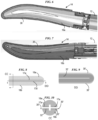
- FIGS. 4-7 illustrate the active electrode 17b in further detail.
- the active electrode 17b includes a first portion 30 and a second portion 32.
- the second electrode portion 32 is in direct contact with the first electrode portion 30 since the first and second portions 30, 32 are part of the same electrode 17b.
- the first portion 30 is defined by a portion of the electrode 17b that has a coating thereon, e.g., the electrode 17b has a coating thereon in the first portion 30 and lacks a coating thereon in the second portion 32.
- the coating allows energy to pass therethrough, but the energy deliverable through the coating, e.g., through the first electrode portion 30 in which the coating is located, requires more power than energy that is deliverable through the electrode 17b without coating, e.g., through the second electrode portion 32 that lacks the coating.
- materials that can form the coating include polytetrafluoroethylene (PTFE).
- the device 100 is thus configured to selectively allow and prevent energy to be delivered through the first electrode portion 30 by varying the voltage provided thereto, with higher voltage, e.g., a voltage above about 400 V or a voltage above about 500 V, allowing energy delivery therethrough and lower voltage, e.g., a voltage below about 300 V or a voltage below about 400 V, preventing energy delivery therethrough.
- the second portion 32 of the electrode 17b is located on a tissue-facing surface of the first jaw 16b.
- a slot 34 extends longitudinally through the second electrode portion 32 and is configured for the compression member 28 (or the device's cutting element if not included on the compression member 28) to slide therein.
- the return electrode 17a on a tissue-facing surface of the second jaw 16a similarly has a slot (obscured in the figures) extending longitudinally therealong in which the compression member 28 (or the device's cutting element if not included on the compression member 28) is configured to slide.
- the first portion 30 of the electrode 17b is in surrounding relation along a perimeter of the second portion 32 of the electrode 17b such that the first portion 30 is positioned laterally outward of the second portion 32.
- the first electrode portion 30 is U-shaped and extends continuously along substantially the entirety of the second electrode portion's longitudinal sides and around a distal tip thereof connecting the second electrode portion's longitudinal sides.
- the first electrode portion 30 may not extend along the entirety of the second electrode portion's longitudinal sides but nevertheless be considered to extend substantially along the entirety of the second electrode portion's longitudinal sides due to any number of factors, such as manufacturing tolerances, sensitivity of measurement equipment, etc.
- the first electrode portion 30 being so shaped and located may help ensure that energy can be applied to tissue as desired by a user of the device 100 with no or minimal reorientation of the end effector 14 within a patient's body since the first electrode portion 30 extends substantially along an entire perimeter of the end effector 14.
- the first electrode portion 30 being located around the distal tip may facilitate targeted energy application to a relatively small area of tissue.
- the first electrode portion 30 being located along the longitudinal sides may facilitate energy application along a length of tissue to allow the entire length to be, e.g., cut and coagulated.
- the first electrode portion 30 can be located only around a distal tip of the second electrode portion 32 and not along the second electrode portion's longitudinal sides, only along the second electrode portion's longitudinal sides and not around the distal tip connecting the longitudinal sides, or along only one of the second electrode portion's longitudinal sides and not around the distal tip connecting the longitudinal sides.
- FIGS. 8-10 illustrate an alternate embodiment of an active electrode 17b' in which a first electrode portion 30' of the electrode 17b' is only along the longitudinal sides of a second electrode portion 32' of the electrode 17b' and not around a distal tip connecting the longitudinal sides.
- the end effector 14 and device 100 including the end effector 14 are otherwise configured and used similar to that discussed above regarding FIGS. 1-7 and can include any number of the alternate features described with respect to FIGS. 1-7 .
- the first electrode portion 30 is configured to be exposed along an edge of the first jaw 16b with the jaws 16a, 16b open ( FIGS. 1, 2 , and 4 ) and with the jaws 16a, 16b closed ( FIGS. 5-7 ).
- the first portion 30 of the electrode 17b overhangs the first jaw 16b.
- the first jaw 16b has a width that is less than a combined width of the first and second electrode portions 30, 32 to facilitate the first electrode portion's overhang.
- the amount of overhang can be, for example, in a range of about 0.010" to 0.30" on each side of the first jaw 16b.
- a total width of the first jaw 16b including the overhang is configured to allow the first jaw 16b to fit through a trocar, such as a 5 mm trocar having an inner diameter in a range of about 0.220" to 0.230".
- the second jaw 16a is substantially the same size as the first jaw 16b, so the second jaw 16a does not prevent the first electrode portion 30 from being exposed when the jaws 16a, 16b are open or when the jaws 16a, 16b are closed.
- the second jaw 16a thus also has a width that is less than a combined width of the first and second electrode portions 30, 32 to facilitate the first electrode portion's overhang.
- first and second jaws 16a, 16b may not be precisely the same size but nevertheless be considered to be substantially the same size due to any number of factors, such as manufacturing tolerances, sensitivity of measurement equipment, etc.
- the exposure of the first electrode portion 30 regardless of whether the jaws 16a, 16b are open or closed provides flexibility to a user of the device 100 since energy can be applied to tissue via the first electrode portion 30 regardless of whether the jaws 16a, 16b are open or closed.
- the second electrode portion 32 is configured to be exposed with the jaws 16a, 16b open and to not be exposed with the jaws 16a, 16b closed.
- the return electrode 17a is configured to be exposed with the jaws 16a, 16b open and to not be exposed with the jaws 16a, 16b closed.
- the first portion 30 of the electrode 17b is configured to delivery energy in the monopolar mode of operation, and the second portion 32 of the electrode 17b is configured to deliver energy in the bipolar mode of operation.
- the same electrode 17b can thus be configured to deliver, at different times, both energy for monopolar functionality and for bipolar functionality.
- the device 100 is configured to selectively operate in the bipolar delivery mode, in which bipolar energy is applied via the second portion 32 of the electrode 17b, and the monopolar delivery mode, in which monopolar energy is applied via the first portion 30 of the electrode 17b.
- the device 100 can be configured to change between the bipolar delivery mode and the monopolar delivery mode in any of a variety of ways.
- the sealing actuator 26 is not a single actuator as illustrated in FIGS. 1 and 2 but instead includes a first sealing actuator configured to be actuated to cause bipolar energy delivery and a second sealing actuator configured to be actuated to cause monopolar energy delivery.
- the one of the first and second actuators that is actuated defines whether the device 100 is in the bipolar delivery mode or the monopolar delivery mode.
- the device 100 includes a mode selector, e.g., a switch, a knob, a lever, etc., accessible at the housing 10 to a user.
- the mode selector is configured to move between a first position, indicative of bipolar delivery mode selection, and a second position, indicative of a monopolar delivery mode selection.
- actuation of the sealing actuator 26 is configured to cause either energy delivery in the bipolar mode of operation (mode selector in the first position) or energy delivery in the monopolar mode of operation (mode selector in the second position).
- the mode selector can be configured to provide a signal to the processor 54 indicative of the mode selector's position, or the sensor 18 of the device 100 can configured to sense whether the mode selector is in the first position or second position and provide a signal to the processor 54 indicative of the mode selector's position.
- the processor 54 is configured to direct energy, e.g., from the generator 52, to the active one of the current path for the device's bipolar energy circuit (bipolar delivery mode) and the current path for the device's monopolar energy circuit (monopolar delivery mode). For monopolar delivery mode the processor 54 is also configured to disable or otherwise inactivate the return electrode 17a or the return electrode's return path.
- Embodiments of changing between monopolar and bipolar delivery modes of a surgical device are further described in U.S. Patent App. No. 16/375,338 entitled “Surgical Devices Switchable Between Monopolar Functionality And Bipolar Functionality” filed on April 4, 2019 , which is incorporated by reference in its entirety.
- the second portion 32 of the electrode 17b is configured to deliver energy in the monopolar mode of operation in addition to the first portion 30 of the electrode 17b being configured to deliver energy in the monopolar mode of operation because the first and second electrode portions 30, 32 are not electrically isolated from one another.
- the entire electrode 17b is configured to deliver energy in the monopolar delivery mode
- the second electrode portion 32 but not the first electrode portion 30 is configured to deliver energy in the bipolar mode of operation.
- the second electrode portion 32 delivering monopolar energy may result in tissue not intended to receive energy delivery nevertheless receiving energy because of the relatively large surface area of the electrode 17b as compared to the first portion 30 of the electrode 17b.
- the active electrode 17b can be configured to be inactive or disabled when the jaws 16a, 16b are open. In this way, energy, whether monopolar or bipolar, cannot be delivered when the jaws 16a, 16b are open. Energy delivery to unintended tissue may thus be less likely.
- the active electrode 17b can be configured to be inactive or disabled when the jaws 16a, 16b are open in any of a variety of ways.
- the electrode 17b being a singular element usable for both the monopolar delivery mode and the bipolar delivery mode may simplify and/or reduce costs of manufacturing the electrode 17b and/or the device 100.
- the electrode 17b can be two electrodes instead of one, with one electrode being configured to deliver energy in the bipolar delivery mode but not energy in the monopolar delivery mode and the other electrode being configured to deliver energy in the monopolar delivery mode but not energy in the bipolar delivery mode. Providing two electrodes may complicate and/or increase costs of manufacturing, but the two electrodes can be electrically isolated from one another to facilitate more targeted delivery of energy in the monopolar delivery mode.
- FIGS. 11-13 illustrate one embodiment of an alternate electrode configuration for the end effector 14 of FIGS. 1 and 2 .
- the return electrode 17a is similarly present on the second jaw 16a.
- the electrode of the first jaw 16a includes a first portion defined by a first, monopolar electrode 36 and a second portion defined by a second, bipolar electrode 38.
- the end effector 14 and device 100 including the end effector 14 are otherwise configured and used similar to that discussed above regarding FIGS. 1-7 and can include any number of the alternate features described with respect to FIGS.
- the first electrode 36 is in surrounding relation around the second electrode 38 similar to that discussed above regarding the first and second portions 30, 32 of the electrode 17b, but in this illustrated embodiment an insulator 40 is disposed or sandwiched between the first and second electrodes 36, 38.
- the insulator 40 is in surrounding relation along a perimeter of the second electrode 38, e.g., is substantially U-shaped similar to the first electrode 36, and is thus configured to electrically isolate the first and second electrodes 36, 38 from one another.
- the monopolar electrode in the embodiment of FIGS. 1-7 extends along both longitudinal sides of the second electrode portion and extends laterally outward from each of the first jaw's longitudinal sides.
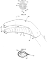
- FIGS. 15-17 illustrate one embodiment similar to the embodiment of FIGS. 8-10 except that a first, monopolar portion 51 of an active electrode 53 extends along only one longitudinal side of a second, bipolar portion 55 of the active electrode 53 and laterally outward from only one longitudinal side of the first jaw 16b.
- FIGS. 18 and 19 illustrate another embodiment similar to the embodiment of FIGS. 15-17 in which a first, monopolar portion 57 of an active electrode 59 extends along only one longitudinal side of a second, bipolar portion 61 of the active electrode 59 and laterally outward from only one longitudinal side of the first jaw 16b.
- the monopolar potion 57 also extends around the distal tip of the bipolar portion 61.
- tissue-contacting surfaces of each of the jaws 16a, 16b e.g., tissue-contacting surfaces of the return electrode 17a and the bipolar portion 61, are curved in this illustrated embodiment instead being substantially planar as in the embodiments of FIGS. 1-17 .
- Any of the embodiments of jaws described herein can have curved or substantially planar tissue-contacting surfaces, with jaws of the same surgical device either each being curved or each being substantially planar.
Landscapes
- Health & Medical Sciences (AREA)
- Surgery (AREA)
- Engineering & Computer Science (AREA)
- Life Sciences & Earth Sciences (AREA)
- Biomedical Technology (AREA)
- Otolaryngology (AREA)
- Nuclear Medicine, Radiotherapy & Molecular Imaging (AREA)
- Plasma & Fusion (AREA)
- Physics & Mathematics (AREA)
- Heart & Thoracic Surgery (AREA)
- Medical Informatics (AREA)
- Molecular Biology (AREA)
- Animal Behavior & Ethology (AREA)
- General Health & Medical Sciences (AREA)
- Public Health (AREA)
- Veterinary Medicine (AREA)
- Surgical Instruments (AREA)
Claims (15)
- Elektrochirurgische Vorrichtung (100), umfassend:ein Gehäuse (10);einen länglichen Schaft (12), der sich von dem Gehäuse erstreckt;einen Endeffektor (14), der mit einem distalen Ende des länglichen Schafts (12) gekoppelt ist, wobei der Endeffektor eine erste und eine zweite Backe (16b, 16a) aufweist, wobei mindestens eine der ersten und der zweiten Backe bezogen auf die andere schwenkbar ist, um den Endeffektor zwischen einer offenen Position und einer geschlossenen Position zu bewegen, undeinen ersten und einen zweiten Elektrodenabschnitt an der ersten Backe (30, 32), wobei der erste Elektrodenabschnitt (30) in umgebender Beziehung entlang eines Umfangs des zweiten Elektrodenabschnitts (32) ist, sodass der erste Elektrodenabschnitt lateral außerhalb des zweiten Elektrodenabschnitts positioniert ist, wobei der erste Elektrodenabschnitt dazu ausgelegt ist, entlang eines Randes der ersten Backe freizuliegen, wenn der Endeffektor in der geschlossenen Position ist und wenn der Endeffektor in der offenen Position ist,wobei in einem bipolaren Betriebsmodus der zweite Elektrodenabschnitt (32) dazu ausgelegt ist, Energie an das vom Endeffektor in Eingriff genommene Gewebe zu liefern, und der erste Elektrodenabschnitt (30) deaktiviert ist und keine Energie an das vom Endeffektor in Eingriff genommene Gewebe liefert, undwobei in einem monopolaren Betriebsmodus der erste Elektrodenabschnitt (30) dazu ausgelegt ist, Energie an Gewebe zu liefern.
- Vorrichtung nach Anspruch 1, wobei in dem monopolaren Betriebsmodus der zweite Elektrodenabschnitt (32) entweder deaktiviert ist und keine Energie an Gewebe liefert oder aktiviert ist und Energie an Gewebe liefert.
- Vorrichtung nach Anspruch 1, wobei die zweite Backe (16a) eine Breite hat, die geringer ist als eine kombinierte Breite des ersten und des zweiten Elektrodenabschnitts.
- Vorrichtung nach Anspruch 1, wobei eine einzelne Elektrode (17b) den ersten und den zweiten Elektrodenabschnitt aufweist, wobei der erste Elektrodenabschnitt (30) in umgebender Beziehung entlang des Umfangs des zweiten Elektrodenabschnitts (32) ist, der in direktem Kontakt mit dem ersten Elektrodenabschnitt ist.
- Vorrichtung nach Anspruch 1, ferner umfassend eine Rückführungselektrode (17a) an der zweiten Backe, wobei die Rückführungselektrode zur Energierückführung im bipolaren Betriebsmodus ausgelegt ist.
- Vorrichtung nach Anspruch 1, wobei der erste Elektrodenabschnitt (30) in umgebender Beziehung entlang des Umfangs des zweiten Elektrodenabschnitts (32) nur entlang einer distalen Spitze der ersten Backe und entlang eines einzelnen Seitenrandes der ersten Backe ist.
- Vorrichtung nach Anspruch 1, wobei der erste Elektrodenabschnitt in umgebender Beziehung entlang des Umfangs des zweiten Elektrodenabschnitts nur entlang eines einzelnen Seitenrandes der ersten Backe ist, wobei optional der monopolare Betriebsmodus nur möglich ist, wenn der Endeffektor in der offenen Position ist.
- Vorrichtung nach Anspruch 1, wobei eine erste Elektrode den ersten Elektrodenabschnitt aufweist,eine zweite andere Elektrode den zweiten Elektrodenabschnitt aufweist, unddie Vorrichtung ferner einen Isolator in umgebender Beziehung entlang des Umfangs der zweiten Elektrode umfasst, um zwischen der ersten und der zweiten Elektrode eingefügt zu werden.
- Vorrichtung nach Anspruch 1, wobei der erste Elektrodenabschnitt in umgebender Beziehung entlang des Umfangs des zweiten Elektrodenabschnitts entlang einer distalen Spitze der ersten Backe und entlang zweier Seitenränder der ersten Backe ist.
- Vorrichtung nach Anspruch 1, wobei eine einzelne Elektrode den ersten und den zweiten Elektrodenabschnitt aufweist, und der erste Elektrodenabschnitt, jedoch nicht der zweite Elektrodenabschnitt, eine Beschichtung hat.
- Elektrochirurgische Vorrichtung nach Anspruch 1, wobeider erste Elektrodenabschnitt dazu ausgelegt ist, Gewebe mit dem Endeffektor in der geschlossenen Position und ohne zwischen der ersten und der zweiten Backe im Eingriff befindliches Gewebe zu kontaktieren,
undwobei der erste Elektrodenabschnitt dazu ausgelegt ist, Energie an Gewebe zu liefern, wenn der Endeffektor in der offenen Position ist und wenn der Endeffektor in der geschlossenen Position ist. - Vorrichtung nach Anspruch 11, wobei eine erste Elektrode den ersten Elektrodenabschnitt aufweist, eine zweite andere Elektrode an der ersten Backe den zweiten Elektrodenabschnitt aufweist,wobei in einem bipolaren Betriebsmodus der zweite Elektrodenabschnitt dazu ausgelegt ist, Energie an das Gewebe zu liefern, und die erste Elektrode deaktiviert ist und keine Energie an das Gewebe liefert,wobei in einem monopolaren Betriebsmodus die erste Elektrode dazu ausgelegt ist, Energie an das Gewebe zu liefern, und der zweite Elektrodenabschnitt deaktiviert ist und keine Energie an das Gewebe liefert, undwobei die Vorrichtung ferner eine Rückführungselektrode an der zweiten Backe umfasst, wobei die Rückführungselektrode zur Energierückführung im bipolaren Betriebsmodus ausgelegt ist.
- Vorrichtung nach Anspruch 1 oder Anspruch 12, ferner umfassend einen Sensor, der dazu ausgelegt ist, zu erfassen, wann der Endeffektor in der geschlossenen Position ist, und
eine Betätigungseinrichtung, die dazu ausgelegt ist, betätigt zu werden, um eine Energielieferung in dem bipolaren Betriebsmodus nur dann zu bewirken, wenn der Endeffektor in der geschlossenen Position ist, wie vom Sensor erfasst. - Vorrichtung nach Anspruch 13, ferner umfassend eine zweite Betätigungseinrichtung, die dazu ausgelegt ist, betätigt zu werden, um eine Energielieferung in dem monopolaren Betriebsmodus zu bewirken.
- Vorrichtung nach Anspruch 9 oder Anspruch 12, wobei der monopolare Betriebsmodus möglich ist, wenn der Endeffektor in der offenen Position und in der geschlossenen Position ist.
Applications Claiming Priority (2)
| Application Number | Priority Date | Filing Date | Title |
|---|---|---|---|
| US16/375,375 US11471212B2 (en) | 2019-04-04 | 2019-04-04 | Electrosurgical devices with monopolar and bipolar functionality |
| PCT/IB2020/052710 WO2020201902A1 (en) | 2019-04-04 | 2020-03-23 | Electrosurgical devices with monopolar and bipolar functionality |
Publications (2)
| Publication Number | Publication Date |
|---|---|
| EP3946115A1 EP3946115A1 (de) | 2022-02-09 |
| EP3946115B1 true EP3946115B1 (de) | 2023-12-20 |
Family
ID=70190015
Family Applications (1)
| Application Number | Title | Priority Date | Filing Date |
|---|---|---|---|
| EP20717285.9A Active EP3946115B1 (de) | 2019-04-04 | 2020-03-23 | Elektrochirurgische vorrichtungen mit monopolarer und bipolarer funktionsfähigkeit |
Country Status (5)
| Country | Link |
|---|---|
| US (1) | US11471212B2 (de) |
| EP (1) | EP3946115B1 (de) |
| JP (1) | JP2022527346A (de) |
| CN (1) | CN113645918A (de) |
| WO (1) | WO2020201902A1 (de) |
Families Citing this family (4)
| Publication number | Priority date | Publication date | Assignee | Title |
|---|---|---|---|---|
| US11737813B2 (en) | 2019-04-25 | 2023-08-29 | M. I. Advanced Thermosurgery, Inc. | Anastomosis device and method |
| US20240268882A1 (en) * | 2021-05-28 | 2024-08-15 | Covidien Lp | Electrosurgical forceps with tissue contact sensing |
| US12514572B2 (en) | 2021-09-22 | 2026-01-06 | Cilag Gmbh International | Separable surgical instrument joints |
| EP4611674A2 (de) * | 2022-11-01 | 2025-09-10 | M. I. Advanced Thermosurgery, Inc. | Elektrochirurgische vorrichtung und verfahren |
Family Cites Families (81)
| Publication number | Priority date | Publication date | Assignee | Title |
|---|---|---|---|---|
| US5403312A (en) * | 1993-07-22 | 1995-04-04 | Ethicon, Inc. | Electrosurgical hemostatic device |
| US5456684A (en) * | 1994-09-08 | 1995-10-10 | Hutchinson Technology Incorporated | Multifunctional minimally invasive surgical instrument |
| US6352536B1 (en) | 2000-02-11 | 2002-03-05 | Sherwood Services Ag | Bipolar electrosurgical instrument for sealing vessels |
| US6228083B1 (en) | 1997-11-14 | 2001-05-08 | Sherwood Services Ag | Laparoscopic bipolar electrosurgical instrument |
| US20030014052A1 (en) | 1997-11-14 | 2003-01-16 | Buysse Steven P. | Laparoscopic bipolar electrosurgical instrument |
| US6068627A (en) | 1997-12-10 | 2000-05-30 | Valleylab, Inc. | Smart recognition apparatus and method |
| US7137980B2 (en) | 1998-10-23 | 2006-11-21 | Sherwood Services Ag | Method and system for controlling output of RF medical generator |
| US6796981B2 (en) | 1999-09-30 | 2004-09-28 | Sherwood Services Ag | Vessel sealing system |
| US7364577B2 (en) | 2002-02-11 | 2008-04-29 | Sherwood Services Ag | Vessel sealing system |
| US20040249374A1 (en) | 1998-10-23 | 2004-12-09 | Tetzlaff Philip M. | Vessel sealing instrument |
| US7267677B2 (en) | 1998-10-23 | 2007-09-11 | Sherwood Services Ag | Vessel sealing instrument |
| US6398779B1 (en) | 1998-10-23 | 2002-06-04 | Sherwood Services Ag | Vessel sealing system |
| US6277117B1 (en) | 1998-10-23 | 2001-08-21 | Sherwood Services Ag | Open vessel sealing forceps with disposable electrodes |
| US7582087B2 (en) | 1998-10-23 | 2009-09-01 | Covidien Ag | Vessel sealing instrument |
| US6511480B1 (en) | 1998-10-23 | 2003-01-28 | Sherwood Services Ag | Open vessel sealing forceps with disposable electrodes |
| US20040167508A1 (en) | 2002-02-11 | 2004-08-26 | Robert Wham | Vessel sealing system |
| US7101372B2 (en) | 2001-04-06 | 2006-09-05 | Sherwood Sevices Ag | Vessel sealer and divider |
| DE60121229T2 (de) | 2001-04-06 | 2007-05-24 | Sherwood Services Ag | Vorrichtung zum abdichten und teilen eines gefässes mit nichtleitendem endanschlag |
| CA2442960C (en) | 2001-04-06 | 2011-03-22 | Sherwood Services Ag | Vessel sealing instrument |
| US7101371B2 (en) | 2001-04-06 | 2006-09-05 | Dycus Sean T | Vessel sealer and divider |
| US7101373B2 (en) | 2001-04-06 | 2006-09-05 | Sherwood Services Ag | Vessel sealer and divider |
| US7118587B2 (en) | 2001-04-06 | 2006-10-10 | Sherwood Services Ag | Vessel sealer and divider |
| CA2733154C (en) | 2002-01-22 | 2012-10-09 | Csaba Truckai | Electrosurgical instrument |
| USD499181S1 (en) | 2003-05-15 | 2004-11-30 | Sherwood Services Ag | Handle for a vessel sealer and divider |
| USD496997S1 (en) | 2003-05-15 | 2004-10-05 | Sherwood Services Ag | Vessel sealer and divider |
| US7156846B2 (en) | 2003-06-13 | 2007-01-02 | Sherwood Services Ag | Vessel sealer and divider for use with small trocars and cannulas |
| US7150749B2 (en) | 2003-06-13 | 2006-12-19 | Sherwood Services Ag | Vessel sealer and divider having elongated knife stroke and safety cutting mechanism |
| US7150097B2 (en) | 2003-06-13 | 2006-12-19 | Sherwood Services Ag | Method of manufacturing jaw assembly for vessel sealer and divider |
| US7597693B2 (en) | 2003-06-13 | 2009-10-06 | Covidien Ag | Vessel sealer and divider for use with small trocars and cannulas |
| US7232440B2 (en) | 2003-11-17 | 2007-06-19 | Sherwood Services Ag | Bipolar forceps having monopolar extension |
| US7131860B2 (en) | 2003-11-20 | 2006-11-07 | Sherwood Services Ag | Connector systems for electrosurgical generator |
| US7169145B2 (en) | 2003-11-21 | 2007-01-30 | Megadyne Medical Products, Inc. | Tuned return electrode with matching inductor |
| GB2408936B (en) * | 2003-12-09 | 2007-07-18 | Gyrus Group Plc | A surgical instrument |
| USD535027S1 (en) | 2004-10-06 | 2007-01-09 | Sherwood Services Ag | Low profile vessel sealing and cutting mechanism |
| USD525361S1 (en) | 2004-10-06 | 2006-07-18 | Sherwood Services Ag | Hemostat style elongated dissecting and dividing instrument |
| USD531311S1 (en) | 2004-10-06 | 2006-10-31 | Sherwood Services Ag | Pistol grip style elongated dissecting and dividing instrument |
| AU2011253698B2 (en) * | 2004-10-21 | 2014-03-06 | Covidien Ag | Bipolar forceps having monopolar extension |
| CA2561034C (en) | 2005-09-30 | 2014-12-09 | Sherwood Services Ag | Flexible endoscopic catheter with an end effector for coagulating and transfecting tissue |
| ES2381560T3 (es) | 2005-09-30 | 2012-05-29 | Covidien Ag | Funda aislante para fórceps electroquirúrgicos |
| US7722607B2 (en) | 2005-09-30 | 2010-05-25 | Covidien Ag | In-line vessel sealer and divider |
| US7789878B2 (en) | 2005-09-30 | 2010-09-07 | Covidien Ag | In-line vessel sealer and divider |
| US7766910B2 (en) | 2006-01-24 | 2010-08-03 | Tyco Healthcare Group Lp | Vessel sealer and divider for large tissue structures |
| US7416101B2 (en) | 2006-01-31 | 2008-08-26 | Ethicon Endo-Surgery, Inc. | Motor-driven surgical cutting and fastening instrument with loading force feedback |
| US7641653B2 (en) | 2006-05-04 | 2010-01-05 | Covidien Ag | Open vessel sealing forceps disposable handswitch |
| USD575395S1 (en) | 2007-02-15 | 2008-08-19 | Tyco Healthcare Group Lp | Hemostat style elongated dissecting and dividing instrument |
| USD649249S1 (en) | 2007-02-15 | 2011-11-22 | Tyco Healthcare Group Lp | End effectors of an elongated dissecting and dividing instrument |
| USD575401S1 (en) | 2007-06-12 | 2008-08-19 | Tyco Healthcare Group Lp | Vessel sealer |
| USD618798S1 (en) | 2009-05-13 | 2010-06-29 | Tyco Healthcare Group Lp | Vessel sealing jaw seal plate |
| USD617900S1 (en) | 2009-05-13 | 2010-06-15 | Tyco Healthcare Group Lp | End effector tip with undercut bottom jaw |
| USD627462S1 (en) | 2009-09-09 | 2010-11-16 | Tyco Healthcare Group Lp | Knife channel of a jaw device |
| US8323310B2 (en) | 2009-09-29 | 2012-12-04 | Covidien Lp | Vessel sealing jaw with offset sealing surface |
| US9005200B2 (en) | 2010-09-30 | 2015-04-14 | Covidien Lp | Vessel sealing instrument |
| US9017372B2 (en) | 2010-10-01 | 2015-04-28 | Covidien Lp | Blade deployment mechanisms for surgical forceps |
| USD670808S1 (en) | 2010-10-01 | 2012-11-13 | Tyco Healthcare Group Lp | Open vessel sealing forceps |
| US9655672B2 (en) | 2010-10-04 | 2017-05-23 | Covidien Lp | Vessel sealing instrument |
| US9492221B2 (en) * | 2011-10-20 | 2016-11-15 | Covidien Lp | Dissection scissors on surgical device |
| US8887373B2 (en) | 2012-02-24 | 2014-11-18 | Covidien Lp | Vessel sealing instrument with reduced thermal spread and method of manufacture therefor |
| USD750245S1 (en) | 2012-03-08 | 2016-02-23 | Covidien Lp | Handle for laparoscopic device with integral rotation wheel |
| USD748260S1 (en) | 2012-03-08 | 2016-01-26 | Covidien Lp | Handle for laparoscopic device with integral rotation wheel |
| USD744100S1 (en) | 2012-03-08 | 2015-11-24 | Covidien Lp | Handle for laparoscopic device |
| US8968311B2 (en) | 2012-05-01 | 2015-03-03 | Covidien Lp | Surgical instrument with stamped double-flag jaws and actuation mechanism |
| US9668807B2 (en) | 2012-05-01 | 2017-06-06 | Covidien Lp | Simplified spring load mechanism for delivering shaft force of a surgical instrument |
| US9039691B2 (en) | 2012-06-29 | 2015-05-26 | Covidien Lp | Surgical forceps |
| US9072524B2 (en) | 2012-06-29 | 2015-07-07 | Covidien Lp | Surgical forceps |
| US9655673B2 (en) | 2013-03-11 | 2017-05-23 | Covidien Lp | Surgical instrument |
| US9456863B2 (en) | 2013-03-11 | 2016-10-04 | Covidien Lp | Surgical instrument with switch activation control |
| WO2014143472A1 (en) * | 2013-03-15 | 2014-09-18 | GYRUS ACMI, INC. (d/b/a OLYMPUS SURGICAL TECHNOLOGIES AMERICA) | Electrosurgical instrument |
| USD726910S1 (en) | 2013-08-07 | 2015-04-14 | Covidien Lp | Reusable forceps for open vessel sealer with mechanical cutter |
| USD744644S1 (en) | 2013-08-07 | 2015-12-01 | Covidien Lp | Disposable housing for open vessel sealer with mechanical cutter |
| USD737439S1 (en) | 2013-08-07 | 2015-08-25 | Covidien Lp | Open vessel sealer with mechanical cutter |
| US9713492B2 (en) | 2013-09-03 | 2017-07-25 | Covidien Lp | Switch assemblies for multi-function surgical instruments and surgical instruments incorporating the same |
| US9717548B2 (en) * | 2013-09-24 | 2017-08-01 | Covidien Lp | Electrode for use in a bipolar electrosurgical instrument |
| USD788302S1 (en) | 2013-10-01 | 2017-05-30 | Covidien Lp | Knife for endoscopic electrosurgical forceps |
| US10278768B2 (en) * | 2014-04-02 | 2019-05-07 | Covidien Lp | Electrosurgical devices including transverse electrode configurations |
| US9675405B2 (en) | 2014-04-08 | 2017-06-13 | Ethicon Llc | Methods and devices for controlling motorized surgical devices |
| US20150313628A1 (en) * | 2014-05-02 | 2015-11-05 | Covidien Lp | Electrosurgical instruments including end-effector assembly configured to provide mechanical cutting action on tissue |
| US10010309B2 (en) | 2014-10-10 | 2018-07-03 | Ethicon Llc | Surgical device with overload mechanism |
| US10010366B2 (en) | 2014-12-17 | 2018-07-03 | Ethicon Llc | Surgical devices and methods for tissue cutting and sealing |
| US10335129B2 (en) | 2015-11-17 | 2019-07-02 | Ethicon Llc | Methods and devices for auto return of articulated end effectors |
| US10555769B2 (en) | 2016-02-22 | 2020-02-11 | Ethicon Llc | Flexible circuits for electrosurgical instrument |
| US10456193B2 (en) * | 2016-05-03 | 2019-10-29 | Ethicon Llc | Medical device with a bilateral jaw configuration for nerve stimulation |
-
2019
- 2019-04-04 US US16/375,375 patent/US11471212B2/en active Active
-
2020
- 2020-03-23 JP JP2021558966A patent/JP2022527346A/ja active Pending
- 2020-03-23 CN CN202080027470.0A patent/CN113645918A/zh active Pending
- 2020-03-23 EP EP20717285.9A patent/EP3946115B1/de active Active
- 2020-03-23 WO PCT/IB2020/052710 patent/WO2020201902A1/en not_active Ceased
Also Published As
| Publication number | Publication date |
|---|---|
| US20200315689A1 (en) | 2020-10-08 |
| WO2020201902A1 (en) | 2020-10-08 |
| US11471212B2 (en) | 2022-10-18 |
| JP2022527346A (ja) | 2022-06-01 |
| CN113645918A (zh) | 2021-11-12 |
| EP3946115A1 (de) | 2022-02-09 |
Similar Documents
| Publication | Publication Date | Title |
|---|---|---|
| US10993762B2 (en) | Dissection scissors on surgical device | |
| US10813683B2 (en) | Bipolar electrosurgical hand shears | |
| US9314295B2 (en) | Dissection scissors on surgical device | |
| US9492224B2 (en) | Multi-function bi-polar forceps | |
| EP1889583B1 (de) | Elektrochirurgische Handinstrumente mit Handschaltern | |
| US20220257310A1 (en) | Monopolar and bipolar functionality | |
| US11471212B2 (en) | Electrosurgical devices with monopolar and bipolar functionality | |
| JP2011521723A (ja) | 外科用器具および方法 | |
| US11241269B2 (en) | Surgical devices switchable between monopolar functionality and bipolar functionality | |
| US20120136347A1 (en) | Electrosurgical instruments and connections thereto | |
| US20200315688A1 (en) | Monopolar and bipolar functionality | |
| US9987071B2 (en) | Surgical instrument with end-effector assembly including three jaw members | |
| US20200222109A1 (en) | Electrosurgical instruments | |
| US11648049B2 (en) | Devices and methods with monopolar and bipolar functionality |
Legal Events
| Date | Code | Title | Description |
|---|---|---|---|
| STAA | Information on the status of an ep patent application or granted ep patent |
Free format text: STATUS: UNKNOWN |
|
| STAA | Information on the status of an ep patent application or granted ep patent |
Free format text: STATUS: THE INTERNATIONAL PUBLICATION HAS BEEN MADE |
|
| PUAI | Public reference made under article 153(3) epc to a published international application that has entered the european phase |
Free format text: ORIGINAL CODE: 0009012 |
|
| STAA | Information on the status of an ep patent application or granted ep patent |
Free format text: STATUS: REQUEST FOR EXAMINATION WAS MADE |
|
| 17P | Request for examination filed |
Effective date: 20211104 |
|
| AK | Designated contracting states |
Kind code of ref document: A1 Designated state(s): AL AT BE BG CH CY CZ DE DK EE ES FI FR GB GR HR HU IE IS IT LI LT LU LV MC MK MT NL NO PL PT RO RS SE SI SK SM TR |
|
| DAV | Request for validation of the european patent (deleted) | ||
| DAX | Request for extension of the european patent (deleted) | ||
| GRAP | Despatch of communication of intention to grant a patent |
Free format text: ORIGINAL CODE: EPIDOSNIGR1 |
|
| STAA | Information on the status of an ep patent application or granted ep patent |
Free format text: STATUS: GRANT OF PATENT IS INTENDED |
|
| INTG | Intention to grant announced |
Effective date: 20230630 |
|
| GRAS | Grant fee paid |
Free format text: ORIGINAL CODE: EPIDOSNIGR3 |
|
| GRAA | (expected) grant |
Free format text: ORIGINAL CODE: 0009210 |
|
| STAA | Information on the status of an ep patent application or granted ep patent |
Free format text: STATUS: THE PATENT HAS BEEN GRANTED |
|
| AK | Designated contracting states |
Kind code of ref document: B1 Designated state(s): AL AT BE BG CH CY CZ DE DK EE ES FI FR GB GR HR HU IE IS IT LI LT LU LV MC MK MT NL NO PL PT RO RS SE SI SK SM TR |
|
| REG | Reference to a national code |
Ref country code: GB Ref legal event code: FG4D |
|
| REG | Reference to a national code |
Ref country code: CH Ref legal event code: EP |
|
| REG | Reference to a national code |
Ref country code: DE Ref legal event code: R096 Ref document number: 602020023048 Country of ref document: DE |
|
| REG | Reference to a national code |
Ref country code: IE Ref legal event code: FG4D |
|
| PG25 | Lapsed in a contracting state [announced via postgrant information from national office to epo] |
Ref country code: GR Free format text: LAPSE BECAUSE OF FAILURE TO SUBMIT A TRANSLATION OF THE DESCRIPTION OR TO PAY THE FEE WITHIN THE PRESCRIBED TIME-LIMIT Effective date: 20240321 |
|
| REG | Reference to a national code |
Ref country code: LT Ref legal event code: MG9D |
|
| PG25 | Lapsed in a contracting state [announced via postgrant information from national office to epo] |
Ref country code: LT Free format text: LAPSE BECAUSE OF FAILURE TO SUBMIT A TRANSLATION OF THE DESCRIPTION OR TO PAY THE FEE WITHIN THE PRESCRIBED TIME-LIMIT Effective date: 20231220 |
|
| REG | Reference to a national code |
Ref country code: NL Ref legal event code: MP Effective date: 20231220 |
|
| PG25 | Lapsed in a contracting state [announced via postgrant information from national office to epo] |
Ref country code: ES Free format text: LAPSE BECAUSE OF FAILURE TO SUBMIT A TRANSLATION OF THE DESCRIPTION OR TO PAY THE FEE WITHIN THE PRESCRIBED TIME-LIMIT Effective date: 20231220 |
|
| PG25 | Lapsed in a contracting state [announced via postgrant information from national office to epo] |
Ref country code: LT Free format text: LAPSE BECAUSE OF FAILURE TO SUBMIT A TRANSLATION OF THE DESCRIPTION OR TO PAY THE FEE WITHIN THE PRESCRIBED TIME-LIMIT Effective date: 20231220 Ref country code: GR Free format text: LAPSE BECAUSE OF FAILURE TO SUBMIT A TRANSLATION OF THE DESCRIPTION OR TO PAY THE FEE WITHIN THE PRESCRIBED TIME-LIMIT Effective date: 20240321 Ref country code: FI Free format text: LAPSE BECAUSE OF FAILURE TO SUBMIT A TRANSLATION OF THE DESCRIPTION OR TO PAY THE FEE WITHIN THE PRESCRIBED TIME-LIMIT Effective date: 20231220 Ref country code: ES Free format text: LAPSE BECAUSE OF FAILURE TO SUBMIT A TRANSLATION OF THE DESCRIPTION OR TO PAY THE FEE WITHIN THE PRESCRIBED TIME-LIMIT Effective date: 20231220 Ref country code: BG Free format text: LAPSE BECAUSE OF FAILURE TO SUBMIT A TRANSLATION OF THE DESCRIPTION OR TO PAY THE FEE WITHIN THE PRESCRIBED TIME-LIMIT Effective date: 20240320 |
|
| REG | Reference to a national code |
Ref country code: AT Ref legal event code: MK05 Ref document number: 1641804 Country of ref document: AT Kind code of ref document: T Effective date: 20231220 |
|
| PG25 | Lapsed in a contracting state [announced via postgrant information from national office to epo] |
Ref country code: NL Free format text: LAPSE BECAUSE OF FAILURE TO SUBMIT A TRANSLATION OF THE DESCRIPTION OR TO PAY THE FEE WITHIN THE PRESCRIBED TIME-LIMIT Effective date: 20231220 |
|
| PG25 | Lapsed in a contracting state [announced via postgrant information from national office to epo] |
Ref country code: SE Free format text: LAPSE BECAUSE OF FAILURE TO SUBMIT A TRANSLATION OF THE DESCRIPTION OR TO PAY THE FEE WITHIN THE PRESCRIBED TIME-LIMIT Effective date: 20231220 Ref country code: RS Free format text: LAPSE BECAUSE OF FAILURE TO SUBMIT A TRANSLATION OF THE DESCRIPTION OR TO PAY THE FEE WITHIN THE PRESCRIBED TIME-LIMIT Effective date: 20231220 Ref country code: NO Free format text: LAPSE BECAUSE OF FAILURE TO SUBMIT A TRANSLATION OF THE DESCRIPTION OR TO PAY THE FEE WITHIN THE PRESCRIBED TIME-LIMIT Effective date: 20240320 Ref country code: NL Free format text: LAPSE BECAUSE OF FAILURE TO SUBMIT A TRANSLATION OF THE DESCRIPTION OR TO PAY THE FEE WITHIN THE PRESCRIBED TIME-LIMIT Effective date: 20231220 Ref country code: LV Free format text: LAPSE BECAUSE OF FAILURE TO SUBMIT A TRANSLATION OF THE DESCRIPTION OR TO PAY THE FEE WITHIN THE PRESCRIBED TIME-LIMIT Effective date: 20231220 Ref country code: HR Free format text: LAPSE BECAUSE OF FAILURE TO SUBMIT A TRANSLATION OF THE DESCRIPTION OR TO PAY THE FEE WITHIN THE PRESCRIBED TIME-LIMIT Effective date: 20231220 |
|
| PG25 | Lapsed in a contracting state [announced via postgrant information from national office to epo] |
Ref country code: IS Free format text: LAPSE BECAUSE OF FAILURE TO SUBMIT A TRANSLATION OF THE DESCRIPTION OR TO PAY THE FEE WITHIN THE PRESCRIBED TIME-LIMIT Effective date: 20240420 |
|
| PG25 | Lapsed in a contracting state [announced via postgrant information from national office to epo] |
Ref country code: CZ Free format text: LAPSE BECAUSE OF FAILURE TO SUBMIT A TRANSLATION OF THE DESCRIPTION OR TO PAY THE FEE WITHIN THE PRESCRIBED TIME-LIMIT Effective date: 20231220 Ref country code: AT Free format text: LAPSE BECAUSE OF FAILURE TO SUBMIT A TRANSLATION OF THE DESCRIPTION OR TO PAY THE FEE WITHIN THE PRESCRIBED TIME-LIMIT Effective date: 20231220 |
|
| PG25 | Lapsed in a contracting state [announced via postgrant information from national office to epo] |
Ref country code: SK Free format text: LAPSE BECAUSE OF FAILURE TO SUBMIT A TRANSLATION OF THE DESCRIPTION OR TO PAY THE FEE WITHIN THE PRESCRIBED TIME-LIMIT Effective date: 20231220 |
|
| PG25 | Lapsed in a contracting state [announced via postgrant information from national office to epo] |
Ref country code: SM Free format text: LAPSE BECAUSE OF FAILURE TO SUBMIT A TRANSLATION OF THE DESCRIPTION OR TO PAY THE FEE WITHIN THE PRESCRIBED TIME-LIMIT Effective date: 20231220 Ref country code: SK Free format text: LAPSE BECAUSE OF FAILURE TO SUBMIT A TRANSLATION OF THE DESCRIPTION OR TO PAY THE FEE WITHIN THE PRESCRIBED TIME-LIMIT Effective date: 20231220 Ref country code: RO Free format text: LAPSE BECAUSE OF FAILURE TO SUBMIT A TRANSLATION OF THE DESCRIPTION OR TO PAY THE FEE WITHIN THE PRESCRIBED TIME-LIMIT Effective date: 20231220 Ref country code: IT Free format text: LAPSE BECAUSE OF FAILURE TO SUBMIT A TRANSLATION OF THE DESCRIPTION OR TO PAY THE FEE WITHIN THE PRESCRIBED TIME-LIMIT Effective date: 20231220 Ref country code: IS Free format text: LAPSE BECAUSE OF FAILURE TO SUBMIT A TRANSLATION OF THE DESCRIPTION OR TO PAY THE FEE WITHIN THE PRESCRIBED TIME-LIMIT Effective date: 20240420 Ref country code: EE Free format text: LAPSE BECAUSE OF FAILURE TO SUBMIT A TRANSLATION OF THE DESCRIPTION OR TO PAY THE FEE WITHIN THE PRESCRIBED TIME-LIMIT Effective date: 20231220 Ref country code: CZ Free format text: LAPSE BECAUSE OF FAILURE TO SUBMIT A TRANSLATION OF THE DESCRIPTION OR TO PAY THE FEE WITHIN THE PRESCRIBED TIME-LIMIT Effective date: 20231220 Ref country code: AT Free format text: LAPSE BECAUSE OF FAILURE TO SUBMIT A TRANSLATION OF THE DESCRIPTION OR TO PAY THE FEE WITHIN THE PRESCRIBED TIME-LIMIT Effective date: 20231220 |
|
| PG25 | Lapsed in a contracting state [announced via postgrant information from national office to epo] |
Ref country code: PL Free format text: LAPSE BECAUSE OF FAILURE TO SUBMIT A TRANSLATION OF THE DESCRIPTION OR TO PAY THE FEE WITHIN THE PRESCRIBED TIME-LIMIT Effective date: 20231220 Ref country code: PT Free format text: LAPSE BECAUSE OF FAILURE TO SUBMIT A TRANSLATION OF THE DESCRIPTION OR TO PAY THE FEE WITHIN THE PRESCRIBED TIME-LIMIT Effective date: 20240422 |
|
| PG25 | Lapsed in a contracting state [announced via postgrant information from national office to epo] |
Ref country code: PT Free format text: LAPSE BECAUSE OF FAILURE TO SUBMIT A TRANSLATION OF THE DESCRIPTION OR TO PAY THE FEE WITHIN THE PRESCRIBED TIME-LIMIT Effective date: 20240422 Ref country code: PL Free format text: LAPSE BECAUSE OF FAILURE TO SUBMIT A TRANSLATION OF THE DESCRIPTION OR TO PAY THE FEE WITHIN THE PRESCRIBED TIME-LIMIT Effective date: 20231220 |
|
| REG | Reference to a national code |
Ref country code: DE Ref legal event code: R097 Ref document number: 602020023048 Country of ref document: DE |
|
| REG | Reference to a national code |
Ref country code: DE Ref legal event code: R119 Ref document number: 602020023048 Country of ref document: DE |
|
| PG25 | Lapsed in a contracting state [announced via postgrant information from national office to epo] |
Ref country code: DK Free format text: LAPSE BECAUSE OF FAILURE TO SUBMIT A TRANSLATION OF THE DESCRIPTION OR TO PAY THE FEE WITHIN THE PRESCRIBED TIME-LIMIT Effective date: 20231220 |
|
| PLBE | No opposition filed within time limit |
Free format text: ORIGINAL CODE: 0009261 |
|
| STAA | Information on the status of an ep patent application or granted ep patent |
Free format text: STATUS: NO OPPOSITION FILED WITHIN TIME LIMIT |
|
| PG25 | Lapsed in a contracting state [announced via postgrant information from national office to epo] |
Ref country code: SI Free format text: LAPSE BECAUSE OF FAILURE TO SUBMIT A TRANSLATION OF THE DESCRIPTION OR TO PAY THE FEE WITHIN THE PRESCRIBED TIME-LIMIT Effective date: 20231220 |
|
| PG25 | Lapsed in a contracting state [announced via postgrant information from national office to epo] |
Ref country code: SI Free format text: LAPSE BECAUSE OF FAILURE TO SUBMIT A TRANSLATION OF THE DESCRIPTION OR TO PAY THE FEE WITHIN THE PRESCRIBED TIME-LIMIT Effective date: 20231220 Ref country code: DK Free format text: LAPSE BECAUSE OF FAILURE TO SUBMIT A TRANSLATION OF THE DESCRIPTION OR TO PAY THE FEE WITHIN THE PRESCRIBED TIME-LIMIT Effective date: 20231220 |
|
| REG | Reference to a national code |
Ref country code: CH Ref legal event code: PL |
|
| PG25 | Lapsed in a contracting state [announced via postgrant information from national office to epo] |
Ref country code: LU Free format text: LAPSE BECAUSE OF NON-PAYMENT OF DUE FEES Effective date: 20240323 |
|
| PG25 | Lapsed in a contracting state [announced via postgrant information from national office to epo] |
Ref country code: MC Free format text: LAPSE BECAUSE OF FAILURE TO SUBMIT A TRANSLATION OF THE DESCRIPTION OR TO PAY THE FEE WITHIN THE PRESCRIBED TIME-LIMIT Effective date: 20231220 |
|
| 26N | No opposition filed |
Effective date: 20240923 |
|
| GBPC | Gb: european patent ceased through non-payment of renewal fee |
Effective date: 20240323 |
|
| PG25 | Lapsed in a contracting state [announced via postgrant information from national office to epo] |
Ref country code: MC Free format text: LAPSE BECAUSE OF FAILURE TO SUBMIT A TRANSLATION OF THE DESCRIPTION OR TO PAY THE FEE WITHIN THE PRESCRIBED TIME-LIMIT Effective date: 20231220 Ref country code: LU Free format text: LAPSE BECAUSE OF NON-PAYMENT OF DUE FEES Effective date: 20240323 |
|
| REG | Reference to a national code |
Ref country code: BE Ref legal event code: MM Effective date: 20240331 |
|
| PG25 | Lapsed in a contracting state [announced via postgrant information from national office to epo] |
Ref country code: DE Free format text: LAPSE BECAUSE OF NON-PAYMENT OF DUE FEES Effective date: 20241001 |
|
| PG25 | Lapsed in a contracting state [announced via postgrant information from national office to epo] |
Ref country code: BE Free format text: LAPSE BECAUSE OF NON-PAYMENT OF DUE FEES Effective date: 20240331 |
|
| PG25 | Lapsed in a contracting state [announced via postgrant information from national office to epo] |
Ref country code: GB Free format text: LAPSE BECAUSE OF NON-PAYMENT OF DUE FEES Effective date: 20240323 |
|
| PG25 | Lapsed in a contracting state [announced via postgrant information from national office to epo] |
Ref country code: FR Free format text: LAPSE BECAUSE OF NON-PAYMENT OF DUE FEES Effective date: 20240331 |
|
| PG25 | Lapsed in a contracting state [announced via postgrant information from national office to epo] |
Ref country code: IE Free format text: LAPSE BECAUSE OF NON-PAYMENT OF DUE FEES Effective date: 20240323 |
|
| PG25 | Lapsed in a contracting state [announced via postgrant information from national office to epo] |
Ref country code: IE Free format text: LAPSE BECAUSE OF NON-PAYMENT OF DUE FEES Effective date: 20240323 Ref country code: GB Free format text: LAPSE BECAUSE OF NON-PAYMENT OF DUE FEES Effective date: 20240323 Ref country code: FR Free format text: LAPSE BECAUSE OF NON-PAYMENT OF DUE FEES Effective date: 20240331 Ref country code: DE Free format text: LAPSE BECAUSE OF NON-PAYMENT OF DUE FEES Effective date: 20241001 Ref country code: BE Free format text: LAPSE BECAUSE OF NON-PAYMENT OF DUE FEES Effective date: 20240331 Ref country code: CH Free format text: LAPSE BECAUSE OF NON-PAYMENT OF DUE FEES Effective date: 20240331 |
|
| PG25 | Lapsed in a contracting state [announced via postgrant information from national office to epo] |
Ref country code: CY Free format text: LAPSE BECAUSE OF FAILURE TO SUBMIT A TRANSLATION OF THE DESCRIPTION OR TO PAY THE FEE WITHIN THE PRESCRIBED TIME-LIMIT; INVALID AB INITIO Effective date: 20200323 |
|
| PG25 | Lapsed in a contracting state [announced via postgrant information from national office to epo] |
Ref country code: HU Free format text: LAPSE BECAUSE OF FAILURE TO SUBMIT A TRANSLATION OF THE DESCRIPTION OR TO PAY THE FEE WITHIN THE PRESCRIBED TIME-LIMIT; INVALID AB INITIO Effective date: 20200323 |
|
| PG25 | Lapsed in a contracting state [announced via postgrant information from national office to epo] |
Ref country code: TR Free format text: LAPSE BECAUSE OF FAILURE TO SUBMIT A TRANSLATION OF THE DESCRIPTION OR TO PAY THE FEE WITHIN THE PRESCRIBED TIME-LIMIT Effective date: 20231220 |