EP3945983B1 - Thin-walled tube with integral external spiral profil for use with endoscope - Google Patents
Thin-walled tube with integral external spiral profil for use with endoscope Download PDFInfo
- Publication number
- EP3945983B1 EP3945983B1 EP20719771.6A EP20719771A EP3945983B1 EP 3945983 B1 EP3945983 B1 EP 3945983B1 EP 20719771 A EP20719771 A EP 20719771A EP 3945983 B1 EP3945983 B1 EP 3945983B1
- Authority
- EP
- European Patent Office
- Prior art keywords
- runner
- hollow tube
- tube
- resin
- spiral
- Prior art date
- Legal status (The legal status is an assumption and is not a legal conclusion. Google has not performed a legal analysis and makes no representation as to the accuracy of the status listed.)
- Active
Links
Images



Classifications
-
- A—HUMAN NECESSITIES
- A61—MEDICAL OR VETERINARY SCIENCE; HYGIENE
- A61B—DIAGNOSIS; SURGERY; IDENTIFICATION
- A61B1/00—Instruments for performing medical examinations of the interior of cavities or tubes of the body by visual or photographical inspection, e.g. endoscopes; Illuminating arrangements therefor
- A61B1/00147—Holding or positioning arrangements
- A61B1/0016—Holding or positioning arrangements using motor drive units
-
- A—HUMAN NECESSITIES
- A61—MEDICAL OR VETERINARY SCIENCE; HYGIENE
- A61B—DIAGNOSIS; SURGERY; IDENTIFICATION
- A61B1/00—Instruments for performing medical examinations of the interior of cavities or tubes of the body by visual or photographical inspection, e.g. endoscopes; Illuminating arrangements therefor
- A61B1/00064—Constructional details of the endoscope body
- A61B1/00071—Insertion part of the endoscope body
-
- A—HUMAN NECESSITIES
- A61—MEDICAL OR VETERINARY SCIENCE; HYGIENE
- A61B—DIAGNOSIS; SURGERY; IDENTIFICATION
- A61B1/00—Instruments for performing medical examinations of the interior of cavities or tubes of the body by visual or photographical inspection, e.g. endoscopes; Illuminating arrangements therefor
- A61B1/00064—Constructional details of the endoscope body
- A61B1/0011—Manufacturing of endoscope parts
-
- A—HUMAN NECESSITIES
- A61—MEDICAL OR VETERINARY SCIENCE; HYGIENE
- A61B—DIAGNOSIS; SURGERY; IDENTIFICATION
- A61B1/00—Instruments for performing medical examinations of the interior of cavities or tubes of the body by visual or photographical inspection, e.g. endoscopes; Illuminating arrangements therefor
- A61B1/00147—Holding or positioning arrangements
-
- A—HUMAN NECESSITIES
- A61—MEDICAL OR VETERINARY SCIENCE; HYGIENE
- A61B—DIAGNOSIS; SURGERY; IDENTIFICATION
- A61B1/00—Instruments for performing medical examinations of the interior of cavities or tubes of the body by visual or photographical inspection, e.g. endoscopes; Illuminating arrangements therefor
- A61B1/00147—Holding or positioning arrangements
- A61B1/00148—Holding or positioning arrangements using anchoring means
-
- A—HUMAN NECESSITIES
- A61—MEDICAL OR VETERINARY SCIENCE; HYGIENE
- A61M—DEVICES FOR INTRODUCING MEDIA INTO, OR ONTO, THE BODY; DEVICES FOR TRANSDUCING BODY MEDIA OR FOR TAKING MEDIA FROM THE BODY; DEVICES FOR PRODUCING OR ENDING SLEEP OR STUPOR
- A61M25/00—Catheters; Hollow probes
- A61M25/0009—Making of catheters or other medical or surgical tubes
- A61M25/0012—Making of catheters or other medical or surgical tubes with embedded structures, e.g. coils, braids, meshes, strands or radiopaque coils
-
- A—HUMAN NECESSITIES
- A61—MEDICAL OR VETERINARY SCIENCE; HYGIENE
- A61M—DEVICES FOR INTRODUCING MEDIA INTO, OR ONTO, THE BODY; DEVICES FOR TRANSDUCING BODY MEDIA OR FOR TAKING MEDIA FROM THE BODY; DEVICES FOR PRODUCING OR ENDING SLEEP OR STUPOR
- A61M25/00—Catheters; Hollow probes
- A61M25/0021—Catheters; Hollow probes characterised by the form of the tubing
-
- A—HUMAN NECESSITIES
- A61—MEDICAL OR VETERINARY SCIENCE; HYGIENE
- A61B—DIAGNOSIS; SURGERY; IDENTIFICATION
- A61B1/00—Instruments for performing medical examinations of the interior of cavities or tubes of the body by visual or photographical inspection, e.g. endoscopes; Illuminating arrangements therefor
- A61B1/00131—Accessories for endoscopes
-
- A—HUMAN NECESSITIES
- A61—MEDICAL OR VETERINARY SCIENCE; HYGIENE
- A61B—DIAGNOSIS; SURGERY; IDENTIFICATION
- A61B1/00—Instruments for performing medical examinations of the interior of cavities or tubes of the body by visual or photographical inspection, e.g. endoscopes; Illuminating arrangements therefor
- A61B1/005—Flexible endoscopes
-
- A—HUMAN NECESSITIES
- A61—MEDICAL OR VETERINARY SCIENCE; HYGIENE
- A61B—DIAGNOSIS; SURGERY; IDENTIFICATION
- A61B17/00—Surgical instruments, devices or methods
- A61B2017/00526—Methods of manufacturing
-
- A—HUMAN NECESSITIES
- A61—MEDICAL OR VETERINARY SCIENCE; HYGIENE
- A61B—DIAGNOSIS; SURGERY; IDENTIFICATION
- A61B17/00—Surgical instruments, devices or methods
- A61B17/34—Trocars; Puncturing needles
- A61B2017/348—Means for supporting the trocar against the body or retaining the trocar inside the body
- A61B2017/3482—Means for supporting the trocar against the body or retaining the trocar inside the body inside
- A61B2017/349—Trocar with thread on outside
-
- B—PERFORMING OPERATIONS; TRANSPORTING
- B29—WORKING OF PLASTICS; WORKING OF SUBSTANCES IN A PLASTIC STATE IN GENERAL
- B29C—SHAPING OR JOINING OF PLASTICS; SHAPING OF MATERIAL IN A PLASTIC STATE, NOT OTHERWISE PROVIDED FOR; AFTER-TREATMENT OF THE SHAPED PRODUCTS, e.g. REPAIRING
- B29C45/00—Injection moulding, i.e. forcing the required volume of moulding material through a nozzle into a closed mould; Apparatus therefor
- B29C45/17—Component parts, details or accessories; Auxiliary operations
- B29C45/26—Moulds
- B29C45/261—Moulds having tubular mould cavities
- B29C45/2612—Moulds having tubular mould cavities for manufacturing tubular articles with an annular groove
-
- B—PERFORMING OPERATIONS; TRANSPORTING
- B29—WORKING OF PLASTICS; WORKING OF SUBSTANCES IN A PLASTIC STATE IN GENERAL
- B29L—INDEXING SCHEME ASSOCIATED WITH SUBCLASS B29C, RELATING TO PARTICULAR ARTICLES
- B29L2031/00—Other particular articles
- B29L2031/753—Medical equipment; Accessories therefor
- B29L2031/7546—Surgical equipment
- B29L2031/7548—Cannulas
-
- F—MECHANICAL ENGINEERING; LIGHTING; HEATING; WEAPONS; BLASTING
- F16—ENGINEERING ELEMENTS AND UNITS; GENERAL MEASURES FOR PRODUCING AND MAINTAINING EFFECTIVE FUNCTIONING OF MACHINES OR INSTALLATIONS; THERMAL INSULATION IN GENERAL
- F16L—PIPES; JOINTS OR FITTINGS FOR PIPES; SUPPORTS FOR PIPES, CABLES OR PROTECTIVE TUBING; MEANS FOR THERMAL INSULATION IN GENERAL
- F16L11/00—Hoses, i.e. flexible pipes
- F16L11/04—Hoses, i.e. flexible pipes made of rubber or flexible plastics
- F16L11/11—Hoses, i.e. flexible pipes made of rubber or flexible plastics with corrugated wall
-
- F—MECHANICAL ENGINEERING; LIGHTING; HEATING; WEAPONS; BLASTING
- F16—ENGINEERING ELEMENTS AND UNITS; GENERAL MEASURES FOR PRODUCING AND MAINTAINING EFFECTIVE FUNCTIONING OF MACHINES OR INSTALLATIONS; THERMAL INSULATION IN GENERAL
- F16L—PIPES; JOINTS OR FITTINGS FOR PIPES; SUPPORTS FOR PIPES, CABLES OR PROTECTIVE TUBING; MEANS FOR THERMAL INSULATION IN GENERAL
- F16L11/00—Hoses, i.e. flexible pipes
- F16L11/04—Hoses, i.e. flexible pipes made of rubber or flexible plastics
- F16L11/11—Hoses, i.e. flexible pipes made of rubber or flexible plastics with corrugated wall
- F16L11/111—Hoses, i.e. flexible pipes made of rubber or flexible plastics with corrugated wall with homogeneous wall
Definitions
- the present disclosure relates generally to thin-walled tubes and more particularly to thin-walled spiral tubes for use with an endoscope and/or endoscope system.
- the invention relates to a polymeric device, wherein the polymeric device is formed as a spiral tube configured to be rotatably attached on an insertion section of an endoscope, and to a polymeric tubular member.
- an insertion section of an insertion apparatus such as an endoscope
- an insertion apparatus such as an endoscope
- a lumen a lumen which is known
- a self-propelled insertion apparatus is a self-propelled insertion apparatus.
- a rotating cylindrical body called a spiral tube is provided, on which a spiral fin is formed on a thin-walled tube.
- the spiral tube is rotatably disposed on an outer circumferential face of an insertion section of the endoscope.
- the spiral fin contacts an inner wall of the lumen, thus generating a propulsion force.
- the insertion section is propelled in a direction of insertion or in a direction of removal.
- the spiral tube presents a very challenging molded part to fill completely during an injection molding process. This is due to the thin-walled tube portion of the spiral tube producing a high resistance to the molten material flow due to its very thin wall, which typically can be about .018 inches thick.
- the definition of "thinwall” is dependent on many factors which contribute to the problem of resin not flowing to ends of an injection molded tube, such as the material flow characteristics, resin pressure, gating, part geometry, and flow length, to name a few.
- Injection molding of thin-walled tubes generally result in an end of the thin-walled tube being incompletely formed because the molten material being injected into the mold cavity has too much resistance to flow due to the thin wall and does not flow completely to the ends of the thin-walled tube.
- spiral tubes are formed of a thin wall tube with a spiral fin attached to the outer circumference of the tube as a secondary operation, such as by the application of Ultraviolet (UV) cure acrylic adhesives, which requires precision dispending and locating and by calibrated light curing.
- UV Ultraviolet
- Such spiral tubes include many additional steps for formation along with an associated increase in manufacturing and quality control costs.
- JP 5985132 B1 discloses an endoscope apparatus, which is configured of an endoscope system having an endoscope and a rotation unit attached to the endoscope.
- the rotation unit has a cylindrical tube body, wherein the tube main body is a disposable tube that is detachably attached to the outer peripheral surface of an insertion portion.
- US 2014/0206942 A1 describes a hybrid cannula comprising a proximal end and a distal end. A first portion of the cannula extends between proximal end and distal end of the hybrid cannula (see Fig. 8b). According to the embodiment in Fig. 8b, threads are provided along the outside of first portion.
- US 4,274,549 A discloses a fuel delivery tube having an inner tube envisioned as an elastomeric extrusion with ribs being formed by an appropriate die during the extrusion process.
- US 6,394,145 A describes a flexible conduit, such as pipe for medical or surgical use.
- the flexible conduit comprises a tube and a helical structure.
- the flexible conduit (cf. Fig. 7 ) is obtained from a profiled strip, which is itself obtained by extrusion, especially of a plastic.
- It is an object of the invention to provide is to provide a single formed polymeric device with well-formed ends for an insertion apparatus, such as an endoscope.
- the object is solved by a polymeric device, wherein the polymeric device is formed as a spiral tube configured to be rotatably attached on an insertion section of an endoscope, according to claim 1.
- the object is solved by a polymeric tubular member according to claim 6.
- the object is also solved by an injection molding process for molding a polymeric device or for molding a polymeric tubular.
- a polymeric device wherein the polymeric device is formed as a spiral tube configured to be rotatably attached on an insertion section of an endoscope.
- the polymeric device comprising: an elongated hollow tube having an outer surface; and a spiral fin wound around the outer surface of the hollow tube; wherein the hollow tube and the spiral fin are formed of a single unitary piece through a molding process, wherein an end portion of the spiral tube includes an internal flow channel in the form of a longitudinal projection having an increased thickness in a radial direction of the hollow tube.
- the polymeric device can further comprise a longitudinal projection projecting from the outer surface of the hollow tube, the longitudinal projection having a greater thickness than other portions of the hollow tube and the longitudinal projection extending at least a portion of a longitudinal length of the hollow tube.
- the longitudinal length of the longitudinal projection can extend from a portion of the spiral fin nearest an end of the hollow tube to the end of the hollow tube.
- the polymeric device can further comprise an end ring formed at an end of the hollow tube, the end ring having a thickness projecting from the outer surface of the hollow tube, the longitudinal length of the longitudinal projection extends from a portion of the spiral fin nearest the end of the hollow tube to the end ring.
- the longitudinal projection can extend at least the portion of the longitudinal length of the hollow tube at a single circumferential position.
- a polymeric tubular member comprising: an elongated hollow tube having an outer surface; a spiral fin wound around the outer surface of the hollow tube; and a longitudinal projection projecting from the outer surface of the hollow tube, the longitudinal projection having a greater thickness than other portions of the hollow tube and the longitudinal projection extending at least a portion of a longitudinal length of the hollow tube; wherein the hollow tube, the spiral fin and the longitudinal projection are formed of a single unitary piece through a molding process, wherein an end portion of the spiral tube includes an internal flow channel in the form of the longitudinal projection having an increased thickness in a radial direction of the hollow tube.
- the longitudinal length of the longitudinal projection can extend from a portion of the spiral fin nearest an end of the hollow tube to the end of the hollow tube.
- the polymeric tubular member can further comprise an end ring formed at an end of the hollow tube, the end ring having a thickness projecting from the outer surface of the hollow tube, the longitudinal length of the longitudinal projection extends from a portion of the spiral fin nearest the end of the hollow tube to the end ring.
- the longitudinal projection can extend at least the portion of the longitudinal length of the hollow tube at a single circumferential position.
- FIG. 1 the same illustrates an endoscope system 200 having a spiral tube 204 rotatably disposed on an insertion section 206 of an endoscope 202.
- the spiral tube 204 is formed in a cylindrical form using an elastic material such as rubber, resin, etc. (generally referred to as a "polymeric tube”), and is rotatably attached to the insertion section 206 around its longitudinal axis.
- the spiral tube 204 includes a spiral-shaped fin 208 provided on an outer circumferential face 210 of a spiral tube 204 such that the spiral-shaped fin 208 extends along a longitudinal length L (see Fig. 5 ) of the spiral tube 210.
- the spiral tube 204 can be configured to be detachable from the insertion section 206.
- the spiral tube 204 is connected to a motor provided as an actuator.
- the motor is connected to a controller 212 via a signal line for motor current signals that pass through an endoscope control body 214 and a universal cable 216 connecting the endoscope 202 and controller 212.
- a propulsion force that propels the insertion section 206 is generated.
- the spiral fin 208 rotating along with the spiral tube 204, crawls along the folds on the inner wall of the small intestine or the large intestine, and thereby a propulsion force acts on the insertion section 206.
- the insertion section 206 is propelled.
- the self-propulsion of the insertion section 206 assists in the tasks of insertion and removal of the insertion section 206 by the user.
- FIG. 2 the same illustrates an end of the spiral tube 204 having the thin-walled tube 210 and the spiral fin 208 integrally formed as a single unitary piece by injection molding.
- Another end of the spiral tube 204 can have the same configuration as that of the end illustrated in FIG. 2 , therefore, such other end is not described or illustrated in FIG. 2 for the sake of brevity.
- the injection molding process includes a series of runners and gates which provide the molten material to a cavity having the form of the spiral tube 204. Such gates typically provide a flow of the molten material to several places at an outermost circumferential position or face of the spiral fin 208.
- the spiral fin 208 typically acts as a gate to provide the molten material to the thin-walled tube 210 portion of the spiral tube 204.
- some portions of the thin-walled tube may not fully fill with the injected molten material, particularly, at the ends of the thin-walled tube where no, or very little, portions of the spiral fin are present, or at portions of the thin-walled tube between spiral fin projections.
- an end portion 220 of the spiral tube 204 includes an internal flow channel 222 in the form of a longitudinal projection having an increased thickness in a radial direction of the thin-walled tube 210.
- Such internal flow channel 222 is integrally formed with the thin-walled tube 210 and has a thickness and circumferential width sufficient to increase the flow of the injected molten material such that the molten material fully and completely fills the end of the thin-walled tube 210.
- the thickness and width of the internal flow channel 222 can vary depending on several factors including the material flow characteristics, gating, part geometry, flow length and injection pressure.
- the thickness and or width of the internal flow channel 222 is/ are a compromise between allowing the resin to flow to the end of the thin-walled tube 210 during injection molding and avoiding detrimentally increasing stiffness of the thin-walled tube 210.
- Sides of the internal flow channel 222 can be angled or curved to form a smooth transition from the outer circumferential surface of the thin-walled tube 210 to an upper surface of the internal flow channel 222.
- the internal flow channel 222 may alternatively have a varying thickness along its length, such as tapering from a greater thickness nearer the spiral fin 208 as compared to a thickness nearer an end of the thin-walled tube 210.
- the longitudinal length of the internal flow channel 222 can be from a nearest spiral fin portion to a further point on an end 226 of the thin-walled tube 210 so as to provide the flow of the molten material from the nearest fin to the end 226.
- the internal flow channel 222 can be formed at the circumferential position of the thin-walled tube 210 where no fin or the least portion of fin is provided so as to act as a gate for transferring the molten material to the end 226 of the thin-walled tube 210. Furthermore, the internal flow channel 222 can project radially outward from an external outer circumferential surface of the thin-walled tube 210. The internal flow channel can be alternatively disposed on the inner diameter of the thin-walled tube 210, for example if the surface is blended to conform with the rest of the thin-walled tube structure.
- the internal flow channel 222 can terminate at the very end 226 of the thin-wall tube, or alternatively, as shown in FIG. 2 , the internal flow channel 222 can terminate at an end ring 224 having an increased thickness, which can be a same thickness as the internal flow channel 222.
- the end ring 224 being in communication with the internal flow channel 222 when molten material is injected in a corresponding mold cavity for the spiral tube 204.
- an internal flow channel can terminate just prior to the end or it can be positioned anywhere along a longitudinal length of the thin-wall tube 210, such as between one or more of the turns of the spiral fin 208.
- the internal flow channel 222 is described and illustrated as being provided in a single circumferential position, more than one internal flow channel 222 can be provided in the circumferential direction to provide symmetry in the circumferential direction, such as 60, 90, 120 or 180 degrees apart.
- the internal flow channel 222 is described as a "flow channel,” the same is only a flow channel while the spiral tube 204 is being molded.
- the term "flow channel” as discussed herein is also used to describe the thickened longitudinal projecting portion of the thin-walled tube that acts as a flow channel during the molding process to transfer molten injected material to flow through the same so as to completely fill a particular area, such as an end of the thin-walled tube, with molten material during the injection molding process.
- the mold for producing the same will have a mold cavity corresponding to the shape of the spiral tube 204, including the internal flow channel 222 in the form of the thickened longitudinal projection.
- the mold cavity for the spiral tube 204 will include a series of runners and gates to provide molten material from an exterior of the mold to the mold cavity, such as to one or more of the turns of the spiral fin, as such runners and gates are known in the art.
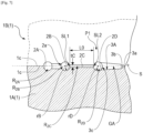
- FIG. 4 is a schematic perspective view showing an example of an injection mold according to the first embodiment.
- FIG. 5 is a schematic partial cross-sectional view of the spiral tube 204 molded article produced by the injection mold according to the first embodiment.
- FIG. 6 is a schematic front view of an injection mold according to the first embodiment.
- FIG. 7 is a cross-sectional view taken along line 7-7 in FIG. 6 .
- FIG. 8 is a partial view of the mold of FIG. 6 showing resin flow during the molding of the spiral tube 204 molded article.
- the shape of the molded thin-walled article produced by the injection mold is not particularly limited.
- the shape of the molded article may be, for example, a box shape, a cylindrical shape, a rod shape, a plate shape, a frame shape, a net shape, or the like, where the corresponding mold cavity would have a corresponding shape.
- the mold configuration of the injection mold can be appropriately selected in accordance with the shape of the molded article to be manufactured by the injection mold.
- the mold configuration of the injection mold may or may not have a slide core.
- the injection mold 1 includes a first slide core 1A, a second slide core 1B, and a core 1C. Although not shown in particular, the injection mold 1 further includes typical members such as a fixed side die plate, a cavity die, and a movable side die plate, for example.
- the injection mold 1 is used for manufacturing the spiral tube 204 by injection molding. As discussed above, the spiral tube 204 a tubular portion 210 and a spiral fin 208 protruding from the tubular portion 210. The wall thickness of the tubular portion 210 is constant in the axial direction with the exception of the internal flow channel 222 and end ring 224.
- the molded spiral tube 204 article has the tubular portion 210 and a spiral fin 208.
- the tubular portion 210 is a thin-walled tube extending along the central axis O.
- the tubular portion 210 has an inner diameter D, a wall thickness t1, a wall thickness at the internal flow channel and/or end ring t2 and a length L.
- L may be 50 mm or more.
- D may be 5 mm to 50 mm.
- t1 may be 0.1 mm to 2 mm and t2 may be an increased thickness over t1 that provides resin flow to the ends of the thin-walled tube 210 under the conditions discussed above while avoiding a detrimental decrease in flexibility.
- the spiral fin 208 protrudes in the radial direction from the outer circumferential surface 54d of the tubular portion 210 over the entire circumference of the outer circumferential surface 54d in a spiral or helical manner.
- the spacing between turns of the spiral fin 208 is not particularly limited.
- the spiral tube 204 shown in FIG. 5 also includes the internal flow channel 222 at each end of the thin-walled tube 210 as well as the end ring 224.
- the internal flow channel 222 extends from the last turn of the spiral fin 208 at each end to the end ring 224.
- the material of the spiral tube 204 is not particularly limited as long as it is a resin material capable of being injection molded.
- the material of the spiral tube 204 may be a hard resin material or a soft resin material such as an elastomer, for example.
- the Z-axis is an axis line extending in the moving direction of the movable side die plate or the like.
- the X-axis is an axis orthogonal to the Z-axis.
- the Y-axis is an axis orthogonal to the X-axis, in a plane including the X-axis but orthogonal to the Z-axis.
- the directions along the X axis, Y axis, and Z axis are referred to as the X-direction, the Y-direction, and the Z-direction, respectively.
- the first slide core 1A and the second slide core 1B are disposed facing each other in the Y-direction.
- the first slide core 1A and the second slide core 1B can be slidably moved in at least the Y-direction when the injection molding die 1 is opened and closed.
- the core 1C is disposed along an axis parallel to the Z-axis.
- the core 1C is fixed to the movable side die plate, and is movable in the Z-direction together with the movable side die plate.
- the first slide core 1A and the second slide core 1B form the shape of the outer periphery of the spiral tube 204.
- the shapes of the first slide core 1A and the second slide core 1B are similar. Therefore, the description will proceed with a focus on the shape of the first slide core 1A.
- the outer shape of the first slide core 1A is a substantially rectangular parallelepiped elongated in the Z-direction.
- the first slide core 1A has a first end face 1a, parallel to the XY plane, at one end in the Z-direction. When the mold is closed, the first end face 1a faces a fixed side mold plate (not shown) of the injection mold 1.
- the first slide core 1A has a second end face 1b, parallel to the XY plane, at the opposite end to the first end face 1a in the Z-direction.
- the second end surface 1b abuts against a movable side die plate (not shown) of the injection mold 1.
- the first slide core 1A has a parting face 1c at the surface facing the second slide core 1B.
- the parting face 1c is a plane parallel to the XZ plane.
- each parting face 1c has a recessed portion which forms the outer shape of the spiral tube 204 when the injection mold 1 is closed.
- a molding space for molding the spiral tube 204 is formed between the recessed portions and the core 1C.
- the recessed portions i.e., the molding surfaces), constituting portions of the molding space, form the outer shape of the spiral tube 204 by transferring the surface shape to the injection resin filled in the molding space.
- Each parting face 1c has a recessed portion for forming a resin flow path for filling molding resin into the molding space.
- the recessed portion forming the molding space is composed of a tubular portion molding surface 4a, a spiral fin molding surface 4b, an internal flow channel molding surface 4c and an end ring molding surface 4d.
- the recessed portion forming the resin flow path is composed of a first resin flow path portion P1 and a second resin flow path portion P2.
- the tubular portion molding surface 4a forms the shape of half the outer circumferential surface 54d of the tubular portion 210.
- the tubular portion molding surface 4a is a semicircular groove extending in the Z-direction with the central axis OA at the center.
- the semicircular groove is defined as a groove having a semicircular cross-sectional shape orthogonal to the extending direction.
- the radius of the semicircle in cross section is referred to as the groove radius.
- the semicircular groove has extending surfaces corresponding to the spiral fin 208, internal flow channels 222 and the end rings 224
- the central axis line OA extends parallel to the Z-axis at the center of the parting face 1c.
- the groove radius of the tubular portion molding surface 4a is D/2.
- the tubular portion molding surface 4a passes through between the first end face 1a and the second end face 1b in the Z-direction.
- the length of the tubular portion molding surface 4a is equal to the total length L of the spiral tube 204.
- the spiral fin molding surface 4b is a recess in the parting face 1c and the tubular portion molding surface 4a.
- the spiral fin molding surface 4b forms the spiral fin 208 of the spiral tube 204.
- the shape of the spiral fin molding surface 4b matches the outer shape of the spiral fin 208.
- the internal flow channel molding surface 4c and end ring molding surface 4d form the internal flow channels 222 and end rings 224 of the spiral tube 204.
- the internal flow channel molding surface 4c and end ring molding surface 4d are formed at two positions corresponding to each end of the spiral tube 204.
- the shape of the internal flow channel molding surface 4c and end ring molding surface 4d matches the outer shape of the respective internal flow channel 222 and end ring 224.
- the core 1C is a cylindrical member having a cylindrical outer circumferential surface 1d.
- the core 1C forms the shape of the inner circumferential surface 54e of the spiral tube 204.
- the outer diameter of the outer circumferential surface 1d of the core 1C is D, which matches the inner diameter of the spiral tube 204.
- the length of the core 1C is L, which corresponds to the length of the spiral tube 204.
- the end faces 1e and 1f formed at both ends in the axial direction of the core 1C are planes orthogonal to the central axis OC of the outer circumferential surface 1d.
- a tubular portion molding surface 4a and the spiral fin molding surface 4b are also formed in the parting face 1c of the second slide core 1B with a central axis OB as the center.
- the coordinate system in FIG. 6 shows the orientation of the first slide core 1A.
- the end ring molding surface 4d is also formed in the parting face 1c of the second slide core 1B. Because the internal flow channel 222 may be non-symmetrically arranged on the thin-walled tube 210, the entirety of the internal flow channel molding surface 4c may be formed on only one of the first slide core 1B or the second slide core 1B or a portion of the internal flow channel molding surface 4c may be formed on each of the first slide core 1B and the second slide core 1B.
- the core 1C is inserted in the Z direction in the center of the inner space surrounded by the tubular portion molding surfaces 4a.
- the end faces 1e and 1f of the core 1C are aligned in the same plane as the first end faces 1a and the second end faces 1b, respectively, of the first slide core 1A and the second slide core 1B.
- a molding space S is formed which is surrounded by the outer circumferential surface 1d of the core 1C, the tubular portion molding surfaces 4a, the spiral fin molding surfaces 4b, the internal flow ring molding surfaces 4c and the end ring molding surfaces 4d.
- the first resin flow path portion P1 and the second resin flow path portion P2 have a symmetric shape with respect to a plane of symmetry passing through the central axis line OA and parallel to the YZ plane.
- the description will proceed with a focus on the shape of the first resin flow path portion P1.
- the first resin flow path portion P1 includes an inlet runner groove 2A, a first runner groove 2B, a second runner groove 2C, a third runner groove 2D, and gate grooves 3A.
- the inlet runner groove 2A is a semicircular groove extending between the injection port 2a and the opening 2b.
- the groove radius of the inlet runner groove 2A is constant.
- the injection port 2a is a semicircular opening provided for the purpose of injecting the injection resin M into the inlet runner groove 2A.
- the injection port 2a is open to the first end face 1a.
- the opening 2b is formed at a position facing, in the X-direction, a central portion of the spiral fin molding surface 4b (i.e., the Z-direction).
- the path of the inlet runner groove 2A is not particularly limited. In FIG. 6 , the inlet runner groove 2A extends in the Z-direction from the injection port 2a, bends in the X-direction away from the central axis OA, bends in the Z-direction toward the reference plane m, and, at a position facing the opening 2b, forms a path that bends in the X-direction toward the opening 2b.
- the inner diameter of the inlet runner groove 2A is set to an appropriate size that allows the molten injection resin M to flow well.
- the first runner groove 2B is a semicircular groove along a path concavely curved toward the central axis OA. Both ends of the first runner groove 2B extend in the X-direction to positions facing the gate grooves 3A, which will be described later, on both sides of the reference plane m and farthest from the reference plane m.
- the first runner groove 2B is symmetric with respect to the reference plane m.
- the curved shape of the first runner groove 2B is set for the purpose of changing the X-direction length of a second runner groove 2C, described later, as a function of the position in the Z-direction.
- the groove radius of the first runner groove 2B is a constant value rB.
- the second runner groove 2C is a recess communicating with a side of the first runner groove 2B facing the third runner groove 2D, which will be described later.
- the depth of the second runner groove 2C from the parting face 1c is tC, where tC ⁇ rB.
- the second runner groove 2C communicates with the first runner groove 2B over substantially the entire length of the first runner groove 2B.
- the width of the second runner groove 2C in the X-direction changes in the Z-direction according to the amount of curvature of the first runner groove 2B.
- the shape of the second runner groove 2C, as viewed in the Y-direction, is symmetric with respect to the reference plane m.
- the third runner groove 2D is a semicircular groove linearly extended in the X-direction.
- the third runner groove 2D is at a position facing the entire first runner groove 2B in the X-direction with the second runner groove 2C interposed therebetween.
- the second runner groove 2C communicates with the third runner groove 2D.
- the length of the third runner groove 2D has the same length as a molding range of the first runner groove 2B in the Z-direction.
- the center of the third runner groove 2D in the Z-direction is located on the reference plane m.
- the groove radius of the third runner groove 2D is a constant value rD, where rD > tC.
- the gate groove 3A is a recessed portion for enabling communication between different portions of the spiral fin molding surface 4b and the third runner groove 2D facing the spiral fin molding surface 4b in the X-direction.
- the gate groove 3A is a semicircular groove having an axis extending in the X-direction as the center.
- the gate groove 3A has a shape obtained by dividing the shape of a pin gate by half from the center.
- a gate opening 3a that opens to the molding space S optimizes the speed of the injection resin M that enters the molding space S are formed at the distal end of the gate groove 3A.
- the radius of the opening 3c communicating with the third runner groove 2D is less than rD.
- the gate grooves 3A divide the injection resin M flowing in the third runner groove 2D in the Z-direction toward the spiral fin molding surface 4b.
- a first resin flow path portion P1 and a second resin flow path portion P2 similar to those in the first slide core 1A are also formed on the parting face 1c of the second slide core 1B.
- the respective first resin flow path portions P1 and the respective second resin flow path portions P2 facing each other in the Y-direction form resin flow paths F1 and F2 having circular and rectangular flow path cross-sections.
- the resin flow paths F1 and F2 each include an inlet runner R 2A (i.e., an upstream runner), a first runner R 2B (i.e., a downstream runner, first circular tube flow path, first runner portion), a second runner R 2C (i.e., a downstream runner, second runner portion, plate-shaped flow path), a third runner R 2D (i.e., a downstream runner, second circular tube flow path, third runner portion), and gates GA.
- inlet runner R 2A i.e., an upstream runner
- a first runner R 2B i.e., a downstream runner, first circular tube flow path, first runner portion
- a second runner R 2C i.e., a downstream runner, second runner portion, plate-shaped flow path
- a third runner R 2D i.e., a downstream runner, second circular tube flow path, third runner portion
- gates GA i.e.,
- the inlet runner R 2A is a flow path formed by combining the inlet runner grooves 2A facing each other in the Y-direction.
- the inlet runner R 2A constitutes an upstream runner having an injection port 2a into which the injection resin M is injected.
- the first runner R 2B , the second runner R 2C , and the third runner R 2D communicate with the inlet runner R 2A and the gates GA and constitute a downstream runner that distributes the injection resin M injected into the injection port 2a to the gates GA.
- the first runner R 2B is a flow path formed by combining the first runner grooves 2 B facing each other in the Y-direction.
- the first runner R 2B is a first circular tube flow path having a first inner diameter of 2xrB. Openings 2b are opened at the center of the first runners R 2B (i.e., a center portion).
- the first runner R 2B faces the respective gates GA, with the second runner R 2C and the third runner R 2D interposed therebetween, and extends along with the positions of the gates GA.
- the second runner R 2C is a flow path formed by combining the second runner R 2C facing each other in the Y-direction.
- the second runner R 2C is a plate-shaped flow path having a flow path width of 2xtC in the thickness direction.
- the second runner R 2C forms a slit SL1 having a width of 2xtC (see FIG. 7 ), which is the same as the flow path width over the approximate overall extending direction of the first runner R 2B on the X-direction side of the first runner R 2B . Since the flow path width is smaller than the first inner diameter, the flow path cross-section of the second runner R 2C has a higher resistance than the flow path cross-section of the first runner R 2B .
- the length of the second runner R 2C in the direction toward the gates GA decreases as the distance from the reference plane m in the extending direction of the first runner R 2B increases; for example, the length of the second runner R 2C at the gate GA at the center in the Z-direction (referred to as the first gate) is L0.
- the length of the second runner R 2C at the point corresponding to the gate GA, disposed next to the central gate GA is L1, where L1 ⁇ L0.
- the length of the second runner R 2C at each gate GA disposed farther from the reference plane m than each gate GA is L2, where L2 ⁇ L1.
- the lengths L0, L1, and L2 are set so that the arrival times of the injection resin M from the opening 2b to the first gate, the gates GA, and the second gates are the same. Each length can be determined, for example, by flow simulation of the injection resin M.
- the third runner R 2D is a flow path formed by combining the third runner R 2D facing each other in the Y-direction.
- the third runner R 2D is a second circular tube flow path having a second inner diameter of 2xrD. Since the second inner diameter is larger than the flow path width of the second runner R 2C , the flow path cross section of the third runner R 2D has a lower resistance than the flow path cross section of the second runner R 2C .
- the second runner R 2C forms a slit SL2 having a width of 2xtC (see FIG. 7 ), which is the same as the flow path width over the approximate overall extending direction of the third runner R 2D on the X-direction side of the third runner R 2D .
- the gate GA is a flow path formed by combining the gate grooves 3A facing each other in the Y-direction.
- the shortest distance of the flow path from the first runner R 2B to each of the gates GA differs depending on the shortest distance between the opening 2b and each of the gates GA.
- the shortest distance in the flow path from the first runner R 2B to the first gate closest to the opening 2b is L0.
- the shortest distance from the first runner R 2B toward the gate is shorter as the shortest distance from the opening 2b to each gate becomes longer, as in L1 and L2.
- FIG. 8 is a view of injection resin flows in the injection mold according to the first embodiment.
- the injection mold 1 When manufacturing the spiral tube 204, the injection mold 1 is attached to an injection molding machine (not shown). While the injection mold 1 is closed, the molding space S and the resin flow paths F1, F2, which communicate with the molding space S through the spiral fin molding surface 4c, are formed inside the assembly consisting of the first slide core 1A, the second slide core 1B, and the core 1C. Each of the injection ports 2a, in the first end face 1a, for the resin flow paths F1, F2 communicates with a sprue (not shown) in a cavity mold plate (not shown).
- the injection resin M injected from an injection molding machine in a molten state is injected into the resin flow paths F1, F2 through the sprue and each of the injection ports 2a.
- the injection amount of the injection resin M is determined in advance according to the sum total volume of the molding space S and the resin flow paths F1 and F2. Since the resin flow paths F1 and F2 are similar flow paths except for being in different positions, an example of only the resin flow path F1 will be described below.
- the injection resin M injected into the injection port 2a for the resin flow path F1 flows along the path in the inlet runner R 2A toward the opening 2b.
- the injection resin M flows in the X-direction in which the distal ends of the inlet runner R 2A extend.
- the injection resin M enters the first runner R 2B from the opening 2b, the injection resin M flows toward both ends of the first runner R 2B . Since the first runner R 2B extends in the Z-direction in the vicinity of the opening 2b, a T-shaped branch flow path branching in two directions, from the X-direction to the Z-direction, is formed in the vicinity of the opening 2b.
- the flow of the injection resin M is bisected into a first runner R 2B toward the first end face 1a and a first runner R 2B toward the second end face 1b. Since the slit SL1 is opened on the side of the first runner R 2B , a part of the resin MC of the injection resin M flows into the second runner R 2C through the slit SL1.
- the opening width (i.e., the width in the Y-direction) of the slit SL1 is smaller than the first inner diameter of the first runner R 2B
- the flow path resistance of the second runner R 2C is larger than the flow path resistance of the first runner R 2B .
- resin MB which is the injection resin M excluding the resin MC, flows in the extending directions of the first runners R 2B .
- the amount of the resin MB is markedly larger than that of the resin MC.
- the flow velocity of the resin MC is proportionally lower than the flow velocity of the resin MB in accordance with the cross-sectional size of the flow path in the flow direction. Therefore, the resin MC fills the first runner R 2B prior to the resin MC passing through the third runner R 2D and flowing into the gates GA.
- the first filling completion time At the time at which the filling of injection resin M in the first runner R 2B is completed (hereinafter referred to as the first filling completion time), an approximately uniform injection pressure is applied to all of injection resin M in the first runner R 2B so that the injection resin M is extruded entirely into the second runner R 2C from the slit SL1.
- the resin MC gradually flows into the second runner R 2C . Since it takes a time corresponding to the length of the first runner R 2B to fill the first runner R 2B with the resin MB, the timing of the resin MC flowing into the second runner R 2C is delayed the farther the position from the reference plane m in the Z-direction. Pressure applied to the resin MC is lower as the distance from the reference plane m in the Z-direction increases. As a result, the amount of the resin MC flowing into the second runner R 2C decreases as the resin MC moves away from the reference plane m in the Z-direction. Similarly, the flow velocity of the resin MC decreases as the resin MC moves away from the reference plane m in the Z-direction.
- the resin MC traveling in the second runner R 2C spreads in a fan-shape in which the flow length of the resin MC at the reference plane m is the longest.
- the front edge of the resin MC becomes flat in accordance with the amount of curvature of the first runner R 2B . Therefore, by appropriately setting the magnitude of the resistivity of the flow path cross-section of the second runner R 2C and the curvature of the first runner R 2B , the difference in the filling times of the second runner R 2C in the Z-direction is reduced.
- the curvature of the first runner R 2B defines the distribution of flow path lengths in the second runner R 2C in the extending direction of the first runner R 2B .
- the front edge of the resin MC becomes flat in the X-direction as the resin MC advances toward the third runner R 2D .
- each position along the Z-direction of the second runner R 2C is filled at substantially the same time.
- the time at which the filling of the second runner R 2C is completed is hereinafter referred to as the second filling completion time.
- the resin MC flowing into the second runner R 2C is turbulent before the first filling completion time. If, in an effort to further downsize the injection mold 1, the length in the X-direction in the second runner R 2C is shortened, the front edge position in the X-direction of the resin MC may vary to some extent as a function of the position in the Z-direction.
- the third runner R 2D in the downstream runner deviations in arrival times of the injection resin M to each of the gates GA due to the disturbance of the front edge of the resin MC are reduced.
- the second inner diameter of the third runner R 2D is larger than the opening width (i.e., the width in the Y-direction) of the slit SL2.
- the resin flowing into the internal flow channel molding spaces 4c allows the resin to flow towards the ends of the tubular portion molding surface 4a to completely fill the molding space S corresponding to the ends of the tubular portion molding surfaces 4a and to further fill the end ring molding surfaces 4d, if provided.
- the injection resin M fills the molding space S through the gates GA since a substantially uniform injection pressure is applied to all of the injection resin M in the downstream runner.
- the injection resin M filled into the molding space S is cooled by conduction of heat to the first slide core 1A, the second slide core 1B, and the core 1C.
- a molded body 50 in which the injection resin M in the injection mold 1 is solidified is formed. Thereafter, the injection mold 1 is opened.
- the molded body 50 includes the spiral tube 204 and flow path resin portions Q1, Q2.
- the flow path resin portion Q1 is formed by solidifying the injection resin M filled in the resin flow path Fl.
- the flow path resin portion Q1 includes a runner resin portion 52 and gate resin portions 53A.
- the runner resin portion 52 is a portion to which the shapes of the upstream runner and the downstream runner are transferred.
- the gate resin portions 53A are portions to which the shapes of the gates GA are transferred, respectively.
- the flow path resin portion Q2 is formed by solidifying the injection resin M filled in the resin channel F2. Like the flow path resin portion Q1, the flow path resin portion Q2 includes a runner resin portion 52 and gate resin portions 53A.
- the molded article 54 is manufactured by separating the flow path resin portions Q1, Q2 from the molded body 50 by secondary operations known in the art.
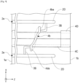
- FIG. 9 there is shown an alternative gating configuration from the gating configuration shown in FIG. 6 in which like features are referenced with like reference characters from FIG. 6 .
- the gates 3B providing resin from runner grooves 2D can alternatively have an output 3a on side surfaces 4ba, 4bb of each turn of the spiral fin molding surface 4b.
- the internal flow channel molding surface 4c can extend from a side surface 4ba of the spiral fin molding surface 4b opposite to the side surface 4bb where the gate 3B enters the spiral fin molding surface 4b.
- such internal flow channel molding surface 4c can extend to a corresponding end of the thin-walled tube molding surface 4a or alternatively, to the end ring molding surface 4d, if provided.
- end ring molding surface 4d can have a similar gate configuration or some of such turns, such as only the end turns, may have the gate configuration of FIG. 9 .
- the internal flow channel 222 described above can be configured to provide a necessary resin flow to the end of a thin-walled tube molded product while maintaining a desired requirement of flexibility, which has particular utility for use in spiral tubes used on an insertion section of an endoscope. Rather than thickening the wall of the entire tube 210 or thickening large portions thereof, the internal flow channel 222 enables a highly controllable and directable plastic flow towards the last area of fill, without detrimentally increasing the bending stiffness of the tube 210.
- the spiral tube 204 in order to be used in endoscopic procedures, must maintain a desired amount of flexibility.
Landscapes
- Health & Medical Sciences (AREA)
- Life Sciences & Earth Sciences (AREA)
- Surgery (AREA)
- Engineering & Computer Science (AREA)
- Heart & Thoracic Surgery (AREA)
- Biophysics (AREA)
- Veterinary Medicine (AREA)
- Public Health (AREA)
- General Health & Medical Sciences (AREA)
- Animal Behavior & Ethology (AREA)
- Biomedical Technology (AREA)
- Medical Informatics (AREA)
- Physics & Mathematics (AREA)
- Molecular Biology (AREA)
- Radiology & Medical Imaging (AREA)
- Pathology (AREA)
- Optics & Photonics (AREA)
- Nuclear Medicine, Radiotherapy & Molecular Imaging (AREA)
- Manufacturing & Machinery (AREA)
- Pulmonology (AREA)
- Anesthesiology (AREA)
- Hematology (AREA)
- Mechanical Engineering (AREA)
- Moulds For Moulding Plastics Or The Like (AREA)
- Instruments For Viewing The Inside Of Hollow Bodies (AREA)
- Endoscopes (AREA)
Description
- The present disclosure relates generally to thin-walled tubes and more particularly to thin-walled spiral tubes for use with an endoscope and/or endoscope system.
- In particular, the invention relates to a polymeric device, wherein the polymeric device is formed as a spiral tube configured to be rotatably attached on an insertion section of an endoscope, and to a polymeric tubular member.
- In general, an insertion section of an insertion apparatus, such as an endoscope, is inserted into, for example, a lumen. One type of such an endoscope inserted into a lumen which is known is a self-propelled insertion apparatus.
- In such a rotary self-propelled insertion apparatus, a rotating cylindrical body called a spiral tube is provided, on which a spiral fin is formed on a thin-walled tube. The spiral tube is rotatably disposed on an outer circumferential face of an insertion section of the endoscope. When the spiral tube rotates, the spiral fin contacts an inner wall of the lumen, thus generating a propulsion force. By this propulsion force, the insertion section is propelled in a direction of insertion or in a direction of removal.
- If the thin-walled tube and spiral fin are formed of a single unitary part, the spiral tube presents a very challenging molded part to fill completely during an injection molding process. This is due to the thin-walled tube portion of the spiral tube producing a high resistance to the molten material flow due to its very thin wall, which typically can be about .018 inches thick. The definition of "thinwall" is dependent on many factors which contribute to the problem of resin not flowing to ends of an injection molded tube, such as the material flow characteristics, resin pressure, gating, part geometry, and flow length, to name a few. Injection molding of thin-walled tubes generally result in an end of the thin-walled tube being incompletely formed because the molten material being injected into the mold cavity has too much resistance to flow due to the thin wall and does not flow completely to the ends of the thin-walled tube.
- Because of such problems, conventional spiral tubes are formed of a thin wall tube with a spiral fin attached to the outer circumference of the tube as a secondary operation, such as by the application of Ultraviolet (UV) cure acrylic adhesives, which requires precision dispending and locating and by calibrated light curing. Such spiral tubes include many additional steps for formation along with an associated increase in manufacturing and quality control costs.
-
US 2010/0069718 A1 discloses catheters, dilators, occluders, stents, suprapubic catheters, camera introducers and related medical devices subject to being proximally propelled and directed for advancement and control in mammalian genitourinary and gastrointestinal passages. Moreover,JP 5985132 B1 US 2014/0206942 A1 describes a hybrid cannula comprising a proximal end and a distal end. A first portion of the cannula extends between proximal end and distal end of the hybrid cannula (see Fig. 8b). According to the embodiment in Fig. 8b, threads are provided along the outside of first portion. -
US 4,274,549 A discloses a fuel delivery tube having an inner tube envisioned as an elastomeric extrusion with ribs being formed by an appropriate die during the extrusion process. - Moreover,
US 6,394,145 A describes a flexible conduit, such as pipe for medical or surgical use. The flexible conduit comprises a tube and a helical structure. The flexible conduit (cf.Fig. 7 ) is obtained from a profiled strip, which is itself obtained by extrusion, especially of a plastic. - It is an object of the invention to provide is to provide a single formed polymeric device with well-formed ends for an insertion apparatus, such as an endoscope.
- The object is solved by a polymeric device, wherein the polymeric device is formed as a spiral tube configured to be rotatably attached on an insertion section of an endoscope, according to
claim 1. In addition the object is solved by a polymeric tubular member according to claim 6. Furthermore, the object is also solved by an injection molding process for molding a polymeric device or for molding a polymeric tubular. - Accordingly, a polymeric device is provided, wherein the polymeric device is formed as a spiral tube configured to be rotatably attached on an insertion section of an endoscope. The polymeric device comprising: an elongated hollow tube having an outer surface; and a spiral fin wound around the outer surface of the hollow tube; wherein the hollow tube and the spiral fin are formed of a single unitary piece through a molding process, wherein an end portion of the spiral tube includes an internal flow channel in the form of a longitudinal projection having an increased thickness in a radial direction of the hollow tube.
- The polymeric device can further comprise a longitudinal projection projecting from the outer surface of the hollow tube, the longitudinal projection having a greater thickness than other portions of the hollow tube and the longitudinal projection extending at least a portion of a longitudinal length of the hollow tube.
- The longitudinal length of the longitudinal projection can extend from a portion of the spiral fin nearest an end of the hollow tube to the end of the hollow tube.
- The polymeric device can further comprise an end ring formed at an end of the hollow tube, the end ring having a thickness projecting from the outer surface of the hollow tube, the longitudinal length of the longitudinal projection extends from a portion of the spiral fin nearest the end of the hollow tube to the end ring.
- The longitudinal projection can extend at least the portion of the longitudinal length of the hollow tube at a single circumferential position.
- Also provided is a polymeric tubular member comprising: an elongated hollow tube having an outer surface; a spiral fin wound around the outer surface of the hollow tube; and a longitudinal projection projecting from the outer surface of the hollow tube, the longitudinal projection having a greater thickness than other portions of the hollow tube and the longitudinal projection extending at least a portion of a longitudinal length of the hollow tube; wherein the hollow tube, the spiral fin and the longitudinal projection are formed of a single unitary piece through a molding process, wherein an end portion of the spiral tube includes an internal flow channel in the form of the longitudinal projection having an increased thickness in a radial direction of the hollow tube.
- The longitudinal length of the longitudinal projection can extend from a portion of the spiral fin nearest an end of the hollow tube to the end of the hollow tube.
- The polymeric tubular member can further comprise an end ring formed at an end of the hollow tube, the end ring having a thickness projecting from the outer surface of the hollow tube, the longitudinal length of the longitudinal projection extends from a portion of the spiral fin nearest the end of the hollow tube to the end ring.
- The longitudinal projection can extend at least the portion of the longitudinal length of the hollow tube at a single circumferential position.
- These and other features, aspects, and advantages of the present invention will become better understood when the following detailed description is read with reference to the accompanying drawings in which like characters represent like parts throughout the drawings, wherein:
-
FIG. 1 illustrates an endoscope system having a spiral tube rotatably disposed on an insertion section of an endoscope. -
FIG. 2 illustrates an end of the spiral tube ofFIG. 2 having an internal flow channel and associated end ring. -
FIG. 3 illustrates a sectional view of the spiral tube ofFIG 3 as taken along line 3-3 inFIG 2 . -
FIG. 4 illustrates a perspective view showing an embodiment of an injection mold for molding the spiral tube ofFIG. 1 . -
FIG. 5 illustrates a partial cross-sectional view of the molded spiral tube produced by an injection mold according to the mold ofFIG. 4 . -
FIG. 6 illustrates a front view of a half of the injection mold ofFIG. 4 . -
FIG. 7 illustrates a cross-sectional view taken along line 7-7 inFIG. 6 . -
FIG. 8 illustrates a view of injection resin flows in the injection mold ofFIG. 4 . -
FIG. 9 illustrates an alternative gating configuration for the mold ofFIG. 6 . - While the disclosed embodiments have particular utility for use with thin-walled spiral tubes for use with endoscopes and are described below with regard to the same, the apparatus and methods disclosed herein are not so limited and have utility to other types of thin-walled tubes, with projections extending therefrom.
- Referring now to
FIG. 1 , the same illustrates anendoscope system 200 having aspiral tube 204 rotatably disposed on aninsertion section 206 of anendoscope 202. Thespiral tube 204 is formed in a cylindrical form using an elastic material such as rubber, resin, etc. (generally referred to as a "polymeric tube"), and is rotatably attached to theinsertion section 206 around its longitudinal axis. Thespiral tube 204 includes a spiral-shaped fin 208 provided on an outercircumferential face 210 of aspiral tube 204 such that the spiral-shaped fin 208 extends along a longitudinal length L (seeFig. 5 ) of thespiral tube 210. Thespiral tube 204 can be configured to be detachable from theinsertion section 206. - The
spiral tube 204 is connected to a motor provided as an actuator. The motor is connected to acontroller 212 via a signal line for motor current signals that pass through anendoscope control body 214 and auniversal cable 216 connecting theendoscope 202 andcontroller 212. - When the
spiral tube 204 rotates in contact with a wall, such as an inner wall of a lumen, a propulsion force that propels theinsertion section 206 is generated. In the small intestine or the large intestine, for example, thespiral fin 208, rotating along with thespiral tube 204, crawls along the folds on the inner wall of the small intestine or the large intestine, and thereby a propulsion force acts on theinsertion section 206. By this propulsion force, theinsertion section 206 is propelled. The self-propulsion of theinsertion section 206 assists in the tasks of insertion and removal of theinsertion section 206 by the user. - Turning next to
FIG. 2 , the same illustrates an end of thespiral tube 204 having the thin-walled tube 210 and thespiral fin 208 integrally formed as a single unitary piece by injection molding. Another end of thespiral tube 204 can have the same configuration as that of the end illustrated inFIG. 2 , therefore, such other end is not described or illustrated inFIG. 2 for the sake of brevity. The injection molding process includes a series of runners and gates which provide the molten material to a cavity having the form of thespiral tube 204. Such gates typically provide a flow of the molten material to several places at an outermost circumferential position or face of thespiral fin 208. In turn, thespiral fin 208 typically acts as a gate to provide the molten material to the thin-walled tube 210 portion of thespiral tube 204. However, in conventional spiral tubes, as discussed above with regard toFIG. 1 , some portions of the thin-walled tube may not fully fill with the injected molten material, particularly, at the ends of the thin-walled tube where no, or very little, portions of the spiral fin are present, or at portions of the thin-walled tube between spiral fin projections. - Referring now to
FIGS. 2 and3 , anend portion 220 of thespiral tube 204 includes aninternal flow channel 222 in the form of a longitudinal projection having an increased thickness in a radial direction of the thin-walled tube 210. Suchinternal flow channel 222 is integrally formed with the thin-walled tube 210 and has a thickness and circumferential width sufficient to increase the flow of the injected molten material such that the molten material fully and completely fills the end of the thin-walled tube 210. The thickness and width of theinternal flow channel 222 can vary depending on several factors including the material flow characteristics, gating, part geometry, flow length and injection pressure. The thickness and or width of theinternal flow channel 222 is/ are a compromise between allowing the resin to flow to the end of the thin-walled tube 210 during injection molding and avoiding detrimentally increasing stiffness of the thin-walled tube 210. Sides of theinternal flow channel 222 can be angled or curved to form a smooth transition from the outer circumferential surface of the thin-walled tube 210 to an upper surface of theinternal flow channel 222. Although illustrated as having a constant thickness along its longitudinal length, theinternal flow channel 222 may alternatively have a varying thickness along its length, such as tapering from a greater thickness nearer thespiral fin 208 as compared to a thickness nearer an end of the thin-walled tube 210. - When the
internal flow channel 222 is provided at the end(s) 220 of thespiral tube 204, the longitudinal length of theinternal flow channel 222 can be from a nearest spiral fin portion to a further point on anend 226 of the thin-walled tube 210 so as to provide the flow of the molten material from the nearest fin to theend 226. Since thespiral fin 208 may not be provided at thevery end 226 of the thin-walled tube 210 or may taper off to a smaller diameter at thevery end 226 of the thin-walled tube 210, theinternal flow channel 222 can be formed at the circumferential position of the thin-walled tube 210 where no fin or the least portion of fin is provided so as to act as a gate for transferring the molten material to theend 226 of the thin-walled tube 210. Furthermore, theinternal flow channel 222 can project radially outward from an external outer circumferential surface of the thin-walled tube 210. The internal flow channel can be alternatively disposed on the inner diameter of the thin-walled tube 210, for example if the surface is blended to conform with the rest of the thin-walled tube structure. - As discussed above, the
internal flow channel 222 can terminate at thevery end 226 of the thin-wall tube, or alternatively, as shown inFIG. 2 , theinternal flow channel 222 can terminate at anend ring 224 having an increased thickness, which can be a same thickness as theinternal flow channel 222. Theend ring 224 being in communication with theinternal flow channel 222 when molten material is injected in a corresponding mold cavity for thespiral tube 204. - Although the
internal flow channel 222 is illustrated with regard to being positioned at the end(s) 226 of the thin-walled tube 210, an internal flow channel can terminate just prior to the end or it can be positioned anywhere along a longitudinal length of the thin-wall tube 210, such as between one or more of the turns of thespiral fin 208. Furthermore, although theinternal flow channel 222 is described and illustrated as being provided in a single circumferential position, more than oneinternal flow channel 222 can be provided in the circumferential direction to provide symmetry in the circumferential direction, such as 60, 90, 120 or 180 degrees apart. - Although the
internal flow channel 222 is described as a "flow channel," the same is only a flow channel while thespiral tube 204 is being molded. Thus, the term "flow channel" as discussed herein is also used to describe the thickened longitudinal projecting portion of the thin-walled tube that acts as a flow channel during the molding process to transfer molten injected material to flow through the same so as to completely fill a particular area, such as an end of the thin-walled tube, with molten material during the injection molding process. - Furthermore, although the
spiral tube 204 is described herein, those skilled in the art will appreciate that the mold for producing the same will have a mold cavity corresponding to the shape of thespiral tube 204, including theinternal flow channel 222 in the form of the thickened longitudinal projection. Those skilled in the art will also appreciate that the mold cavity for thespiral tube 204 will include a series of runners and gates to provide molten material from an exterior of the mold to the mold cavity, such as to one or more of the turns of the spiral fin, as such runners and gates are known in the art. - An injection mold according to a first embodiment will be described with regard to
FIGS. 4-8 .FIG. 4 is a schematic perspective view showing an example of an injection mold according to the first embodiment.FIG. 5 is a schematic partial cross-sectional view of thespiral tube 204 molded article produced by the injection mold according to the first embodiment.FIG. 6 is a schematic front view of an injection mold according to the first embodiment.FIG. 7 is a cross-sectional view taken along line 7-7 inFIG. 6 .FIG. 8 is a partial view of the mold ofFIG. 6 showing resin flow during the molding of thespiral tube 204 molded article. As discussed above, the shape of the molded thin-walled article produced by the injection mold is not particularly limited. The shape of the molded article may be, for example, a box shape, a cylindrical shape, a rod shape, a plate shape, a frame shape, a net shape, or the like, where the corresponding mold cavity would have a corresponding shape. - The mold configuration of the injection mold can be appropriately selected in accordance with the shape of the molded article to be manufactured by the injection mold. For example, the mold configuration of the injection mold may or may not have a slide core.
- Hereinafter, an example is described of an
injection mold 1 for manufacturing the thin-walled molded article (spiral tube 204) (seeFIG. 5 ) as shown inFIG. 4 . - As shown in
FIG. 4 , theinjection mold 1 includes afirst slide core 1A, asecond slide core 1B, and acore 1C. Although not shown in particular, theinjection mold 1 further includes typical members such as a fixed side die plate, a cavity die, and a movable side die plate, for example. - The
injection mold 1 is used for manufacturing thespiral tube 204 by injection molding. As discussed above, the spiral tube 204 atubular portion 210 and aspiral fin 208 protruding from thetubular portion 210. The wall thickness of thetubular portion 210 is constant in the axial direction with the exception of theinternal flow channel 222 andend ring 224. - As shown in
FIG. 5 , the moldedspiral tube 204 article has thetubular portion 210 and aspiral fin 208. Thetubular portion 210 is a thin-walled tube extending along the central axis O. Thetubular portion 210 has an inner diameter D, a wall thickness t1, a wall thickness at the internal flow channel and/or end ring t2 and a length L. For example, L may be 50 mm or more. D may be 5 mm to 50 mm. t1 may be 0.1 mm to 2 mm and t2 may be an increased thickness over t1 that provides resin flow to the ends of the thin-walled tube 210 under the conditions discussed above while avoiding a detrimental decrease in flexibility. Thespiral fin 208 protrudes in the radial direction from the outercircumferential surface 54d of thetubular portion 210 over the entire circumference of the outercircumferential surface 54d in a spiral or helical manner. The spacing between turns of thespiral fin 208 is not particularly limited. - The
spiral tube 204 shown inFIG. 5 , also includes theinternal flow channel 222 at each end of the thin-walled tube 210 as well as theend ring 224. In the configuration shown inFigure 5 , theinternal flow channel 222 extends from the last turn of thespiral fin 208 at each end to theend ring 224. - The material of the
spiral tube 204 is not particularly limited as long as it is a resin material capable of being injection molded. The material of thespiral tube 204 may be a hard resin material or a soft resin material such as an elastomer, for example. - Next, the injection molding die 1 for forming the
spiral tube 204 will be described. - Hereinafter, descriptions will be given with reference to the XYZ orthogonal coordinate system shown in
FIG. 4 . The Z-axis is an axis line extending in the moving direction of the movable side die plate or the like. The X-axis is an axis orthogonal to the Z-axis. The Y-axis is an axis orthogonal to the X-axis, in a plane including the X-axis but orthogonal to the Z-axis. The directions along the X axis, Y axis, and Z axis are referred to as the X-direction, the Y-direction, and the Z-direction, respectively. - The
first slide core 1A and thesecond slide core 1B are disposed facing each other in the Y-direction. Thefirst slide core 1A and thesecond slide core 1B can be slidably moved in at least the Y-direction when the injection molding die 1 is opened and closed. Thecore 1C is disposed along an axis parallel to the Z-axis. Thecore 1C is fixed to the movable side die plate, and is movable in the Z-direction together with the movable side die plate. Thefirst slide core 1A and thesecond slide core 1B form the shape of the outer periphery of thespiral tube 204. - The shapes of the
first slide core 1A and thesecond slide core 1B are similar. Therefore, the description will proceed with a focus on the shape of thefirst slide core 1A. - The outer shape of the
first slide core 1A is a substantially rectangular parallelepiped elongated in the Z-direction. Thefirst slide core 1A has afirst end face 1a, parallel to the XY plane, at one end in the Z-direction. When the mold is closed, thefirst end face 1a faces a fixed side mold plate (not shown) of theinjection mold 1. - The
first slide core 1A has asecond end face 1b, parallel to the XY plane, at the opposite end to thefirst end face 1a in the Z-direction. When the mold is closed, thesecond end surface 1b abuts against a movable side die plate (not shown) of theinjection mold 1. - The
first slide core 1A has aparting face 1c at the surface facing thesecond slide core 1B. The parting face 1c is a plane parallel to the XZ plane. In each parting face 1c has a recessed portion which forms the outer shape of thespiral tube 204 when theinjection mold 1 is closed. A molding space for molding thespiral tube 204 is formed between the recessed portions and thecore 1C. The recessed portions (i.e., the molding surfaces), constituting portions of the molding space, form the outer shape of thespiral tube 204 by transferring the surface shape to the injection resin filled in the molding space. - Each parting face 1c has a recessed portion for forming a resin flow path for filling molding resin into the molding space. The recessed portion forming the molding space is composed of a tubular
portion molding surface 4a, a spiralfin molding surface 4b, an internal flowchannel molding surface 4c and an endring molding surface 4d. The recessed portion forming the resin flow path is composed of a first resin flow path portion P1 and a second resin flow path portion P2. - The tubular
portion molding surface 4a forms the shape of half the outercircumferential surface 54d of thetubular portion 210. The tubularportion molding surface 4a is a semicircular groove extending in the Z-direction with the central axis OA at the center. The semicircular groove is defined as a groove having a semicircular cross-sectional shape orthogonal to the extending direction. In a semicircular groove, the radius of the semicircle in cross section is referred to as the groove radius. The semicircular groove has extending surfaces corresponding to thespiral fin 208,internal flow channels 222 and the end rings 224 - The central axis line OA extends parallel to the Z-axis at the center of the
parting face 1c. The groove radius of the tubularportion molding surface 4a is D/2. The tubularportion molding surface 4a passes through between thefirst end face 1a and thesecond end face 1b in the Z-direction. The length of the tubularportion molding surface 4a is equal to the total length L of thespiral tube 204. - As shown in
FIG. 6 , the spiralfin molding surface 4b is a recess in theparting face 1c and the tubularportion molding surface 4a. The spiralfin molding surface 4b forms thespiral fin 208 of thespiral tube 204. The shape of the spiralfin molding surface 4b matches the outer shape of thespiral fin 208. Similarly, the internal flowchannel molding surface 4c and endring molding surface 4d form theinternal flow channels 222 and end rings 224 of thespiral tube 204. The internal flowchannel molding surface 4c and endring molding surface 4d are formed at two positions corresponding to each end of thespiral tube 204. The shape of the internal flowchannel molding surface 4c and endring molding surface 4d matches the outer shape of the respectiveinternal flow channel 222 andend ring 224. - As shown in
FIG. 4 , thecore 1C is a cylindrical member having a cylindrical outercircumferential surface 1d. The core 1C forms the shape of the inner circumferential surface 54e of thespiral tube 204. The outer diameter of the outercircumferential surface 1d of thecore 1C is D, which matches the inner diameter of thespiral tube 204. The length of thecore 1C is L, which corresponds to the length of thespiral tube 204. The end faces 1e and 1f formed at both ends in the axial direction of thecore 1C are planes orthogonal to the central axis OC of the outercircumferential surface 1d. - Similar to the
first slide core 1A, a tubularportion molding surface 4a and the spiralfin molding surface 4b are also formed in theparting face 1c of thesecond slide core 1B with a central axis OB as the center. However, the coordinate system inFIG. 6 shows the orientation of thefirst slide core 1A. The endring molding surface 4d is also formed in theparting face 1c of thesecond slide core 1B. Because theinternal flow channel 222 may be non-symmetrically arranged on the thin-walled tube 210, the entirety of the internal flowchannel molding surface 4c may be formed on only one of thefirst slide core 1B or thesecond slide core 1B or a portion of the internal flowchannel molding surface 4c may be formed on each of thefirst slide core 1B and thesecond slide core 1B. - When the respective parting faces 1c of the
first slide core 1A and thesecond slide core 1B abut when theinjection mold 1 is closed, the central axes OA and OB coincide with each other. At this time, the tubularportion molding surfaces 4a, thespiral fin 4b molding surface 4b, the internal flowchannel molding surfaces 4c and the endring molding surfaces 4d facing each other in the Y-direction form the shape of the outer circumferential surface of thespiral tube 204. - As indicated by a two-dot chain line, the
core 1C is inserted in the Z direction in the center of the inner space surrounded by the tubularportion molding surfaces 4a. The end faces 1e and 1f of thecore 1C are aligned in the same plane as the first end faces 1a and the second end faces 1b, respectively, of thefirst slide core 1A and thesecond slide core 1B. - As a result, a molding space S is formed which is surrounded by the outer
circumferential surface 1d of thecore 1C, the tubularportion molding surfaces 4a, the spiralfin molding surfaces 4b, the internal flow ring molding surfaces 4c and the endring molding surfaces 4d. - The first resin flow path portion P1 and the second resin flow path portion P2 have a symmetric shape with respect to a plane of symmetry passing through the central axis line OA and parallel to the YZ plane. Hereinafter, the description will proceed with a focus on the shape of the first resin flow path portion P1.
- The first resin flow path portion P1 includes an
inlet runner groove 2A, afirst runner groove 2B, asecond runner groove 2C, athird runner groove 2D, andgate grooves 3A. Theinlet runner groove 2A is a semicircular groove extending between theinjection port 2a and theopening 2b. The groove radius of theinlet runner groove 2A is constant. Theinjection port 2a is a semicircular opening provided for the purpose of injecting the injection resin M into theinlet runner groove 2A. Theinjection port 2a is open to thefirst end face 1a. - The
opening 2b is formed at a position facing, in the X-direction, a central portion of the spiralfin molding surface 4b (i.e., the Z-direction). The path of theinlet runner groove 2A is not particularly limited. InFIG. 6 , theinlet runner groove 2A extends in the Z-direction from theinjection port 2a, bends in the X-direction away from the central axis OA, bends in the Z-direction toward the reference plane m, and, at a position facing theopening 2b, forms a path that bends in the X-direction toward theopening 2b. The inner diameter of theinlet runner groove 2A is set to an appropriate size that allows the molten injection resin M to flow well. - The
first runner groove 2B is a semicircular groove along a path concavely curved toward the central axis OA. Both ends of thefirst runner groove 2B extend in the X-direction to positions facing thegate grooves 3A, which will be described later, on both sides of the reference plane m and farthest from the reference plane m. Thefirst runner groove 2B is symmetric with respect to the reference plane m. The curved shape of thefirst runner groove 2B is set for the purpose of changing the X-direction length of asecond runner groove 2C, described later, as a function of the position in the Z-direction. - As shown in
FIG. 7 , the groove radius of thefirst runner groove 2B is a constant value rB. As shown inFIG. 7 , thesecond runner groove 2C is a recess communicating with a side of thefirst runner groove 2B facing thethird runner groove 2D, which will be described later. The depth of the second runner groove 2C from the parting face 1c is tC, where tC < rB. - As shown in
FIG. 6 , thesecond runner groove 2C communicates with thefirst runner groove 2B over substantially the entire length of thefirst runner groove 2B. The width of the second runner groove 2C in the X-direction changes in the Z-direction according to the amount of curvature of thefirst runner groove 2B. Further, the shape of thesecond runner groove 2C, as viewed in the Y-direction, is symmetric with respect to the reference plane m. - The
third runner groove 2D is a semicircular groove linearly extended in the X-direction. Thethird runner groove 2D is at a position facing the entirefirst runner groove 2B in the X-direction with the second runner groove 2C interposed therebetween. Thesecond runner groove 2C communicates with thethird runner groove 2D. The length of thethird runner groove 2D has the same length as a molding range of thefirst runner groove 2B in the Z-direction. The center of thethird runner groove 2D in the Z-direction is located on the reference plane m. As shown inFIG. 7 , the groove radius of thethird runner groove 2D is a constant value rD, where rD > tC. - The
gate groove 3A is a recessed portion for enabling communication between different portions of the spiralfin molding surface 4b and thethird runner groove 2D facing the spiralfin molding surface 4b in the X-direction. Thegate groove 3A is a semicircular groove having an axis extending in the X-direction as the center. For example, thegate groove 3A has a shape obtained by dividing the shape of a pin gate by half from the center. As shown inFIG. 7 , agate opening 3a that opens to the molding space S optimizes the speed of the injection resin M that enters the molding space S are formed at the distal end of thegate groove 3A. In thegate groove 3A, the radius of theopening 3c communicating with thethird runner groove 2D is less than rD. Thegate grooves 3A divide the injection resin M flowing in thethird runner groove 2D in the Z-direction toward the spiralfin molding surface 4b. - As shown in
FIG. 6 , a first resin flow path portion P1 and a second resin flow path portion P2 similar to those in thefirst slide core 1A are also formed on theparting face 1c of thesecond slide core 1B. When the respective parting faces 1c of thefirst slide core 1A and thesecond slide core 1B come in contact with each other when the injection molding die 1 is closed, the respective first resin flow path portions P1 and the respective second resin flow path portions P2 facing each other in the Y-direction form resin flow paths F1 and F2 having circular and rectangular flow path cross-sections. - The resin flow paths F1 and F2 each include an inlet runner R2A (i.e., an upstream runner), a first runner R2B (i.e., a downstream runner, first circular tube flow path, first runner portion), a second runner R2C (i.e., a downstream runner, second runner portion, plate-shaped flow path), a third runner R2D (i.e., a downstream runner, second circular tube flow path, third runner portion), and gates GA.
- The inlet runner R2A is a flow path formed by combining the
inlet runner grooves 2A facing each other in the Y-direction. The inlet runner R2A constitutes an upstream runner having aninjection port 2a into which the injection resin M is injected. The first runner R2B, the second runner R2C, and the third runner R2D communicate with the inlet runner R2A and the gates GA and constitute a downstream runner that distributes the injection resin M injected into theinjection port 2a to the gates GA. - The first runner R2B is a flow path formed by combining the
first runner grooves 2B facing each other in the Y-direction. The first runner R2B is a first circular tube flow path having a first inner diameter of 2xrB.Openings 2b are opened at the center of the first runners R2B (i.e., a center portion). The first runner R2B faces the respective gates GA, with the second runner R2C and the third runner R2D interposed therebetween, and extends along with the positions of the gates GA. - The second runner R2C is a flow path formed by combining the second runner R2C facing each other in the Y-direction. The second runner R2C is a plate-shaped flow path having a flow path width of 2xtC in the thickness direction. The second runner R2C forms a slit SL1 having a width of 2xtC (see
FIG. 7 ), which is the same as the flow path width over the approximate overall extending direction of the first runner R2B on the X-direction side of the first runner R2B. Since the flow path width is smaller than the first inner diameter, the flow path cross-section of the second runner R2C has a higher resistance than the flow path cross-section of the first runner R2B. - As shown in
FIG. 6 , the length of the second runner R2C in the direction toward the gates GA (i.e., the X-direction) decreases as the distance from the reference plane m in the extending direction of the first runner R2B increases; for example, the length of the second runner R2C at the gate GA at the center in the Z-direction (referred to as the first gate) is L0. The length of the second runner R2C at the point corresponding to the gate GA, disposed next to the central gate GA, is L1, where L1 < L0. The length of the second runner R2C at each gate GA disposed farther from the reference plane m than each gate GA is L2, where L2 < L1. The lengths L0, L1, and L2 are set so that the arrival times of the injection resin M from theopening 2b to the first gate, the gates GA, and the second gates are the same. Each length can be determined, for example, by flow simulation of the injection resin M. - The third runner R2D is a flow path formed by combining the third runner R2D facing each other in the Y-direction. The third runner R2D is a second circular tube flow path having a second inner diameter of 2xrD. Since the second inner diameter is larger than the flow path width of the second runner R2C, the flow path cross section of the third runner R2D has a lower resistance than the flow path cross section of the second runner R2C. The second runner R2C forms a slit SL2 having a width of 2xtC (see
FIG. 7 ), which is the same as the flow path width over the approximate overall extending direction of the third runner R2D on the X-direction side of the third runner R2D. The gate GA is a flow path formed by combining thegate grooves 3A facing each other in the Y-direction. - With such a configuration, in the second runner R2C, the shortest distance of the flow path from the first runner R2B to each of the gates GA differs depending on the shortest distance between the
opening 2b and each of the gates GA. For example, in the second runner R2C, the shortest distance in the flow path from the first runner R2B to the first gate closest to theopening 2b is L0. On the other hand, in the flow path of the first runner R2B in which the shortest distance from theopening 2b sequentially becomes longer, the flow path of the second runner R2C at the point corresponding to the second gate, the shortest distance from the first runner R2B toward the gate is shorter as the shortest distance from theopening 2b to each gate becomes longer, as in L1 and L2. - A manufacturing process of the
spiral tube 204 using theinjection mold 1 will now be described with reference toFIG. 8. FIG. 8 is a view of injection resin flows in the injection mold according to the first embodiment. - When manufacturing the
spiral tube 204, theinjection mold 1 is attached to an injection molding machine (not shown). While theinjection mold 1 is closed, the molding space S and the resin flow paths F1, F2, which communicate with the molding space S through the spiralfin molding surface 4c, are formed inside the assembly consisting of thefirst slide core 1A, thesecond slide core 1B, and thecore 1C. Each of theinjection ports 2a, in thefirst end face 1a, for the resin flow paths F1, F2 communicates with a sprue (not shown) in a cavity mold plate (not shown). - The injection resin M injected from an injection molding machine in a molten state is injected into the resin flow paths F1, F2 through the sprue and each of the
injection ports 2a. The injection amount of the injection resin M is determined in advance according to the sum total volume of the molding space S and the resin flow paths F1 and F2. Since the resin flow paths F1 and F2 are similar flow paths except for being in different positions, an example of only the resin flow path F1 will be described below. - As shown in
FIG. 8 , the injection resin M injected into theinjection port 2a for the resin flow path F1 flows along the path in the inlet runner R2A toward theopening 2b. In the vicinity of theopening 2b, the injection resin M flows in the X-direction in which the distal ends of the inlet runner R2A extend. When the injection resin M enters the first runner R2B from theopening 2b, the injection resin M flows toward both ends of the first runner R2B. Since the first runner R2B extends in the Z-direction in the vicinity of theopening 2b, a T-shaped branch flow path branching in two directions, from the X-direction to the Z-direction, is formed in the vicinity of theopening 2b. Therefore, the flow of the injection resin M is bisected into a first runner R2B toward thefirst end face 1a and a first runner R2B toward thesecond end face 1b. Since the slit SL1 is opened on the side of the first runner R2B, a part of the resin MC of the injection resin M flows into the second runner R2C through the slit SL1. - However, since the opening width (i.e., the width in the Y-direction) of the slit SL1 is smaller than the first inner diameter of the first runner R2B, the flow path resistance of the second runner R2C is larger than the flow path resistance of the first runner R2B. As a result, resin MB, which is the injection resin M excluding the resin MC, flows in the extending directions of the first runners R2B. The amount of the resin MB is markedly larger than that of the resin MC.
- The flow velocity of the resin MC is proportionally lower than the flow velocity of the resin MB in accordance with the cross-sectional size of the flow path in the flow direction. Therefore, the resin MC fills the first runner R2B prior to the resin MC passing through the third runner R2D and flowing into the gates GA. At the time at which the filling of injection resin M in the first runner R2B is completed (hereinafter referred to as the first filling completion time), an approximately uniform injection pressure is applied to all of injection resin M in the first runner R2B so that the injection resin M is extruded entirely into the second runner R2C from the slit SL1.
- Until the first filling completion time, the resin MC gradually flows into the second runner R2C. Since it takes a time corresponding to the length of the first runner R2B to fill the first runner R2B with the resin MB, the timing of the resin MC flowing into the second runner R2C is delayed the farther the position from the reference plane m in the Z-direction. Pressure applied to the resin MC is lower as the distance from the reference plane m in the Z-direction increases. As a result, the amount of the resin MC flowing into the second runner R2C decreases as the resin MC moves away from the reference plane m in the Z-direction. Similarly, the flow velocity of the resin MC decreases as the resin MC moves away from the reference plane m in the Z-direction.
- Therefore, when the first runner R2B is linear, the resin MC traveling in the second runner R2C spreads in a fan-shape in which the flow length of the resin MC at the reference plane m is the longest. However, since the first runner R2B is concavely curved toward the third runner R2D, the front edge of the resin MC becomes flat in accordance with the amount of curvature of the first runner R2B. Therefore, by appropriately setting the magnitude of the resistivity of the flow path cross-section of the second runner R2C and the curvature of the first runner R2B, the difference in the filling times of the second runner R2C in the Z-direction is reduced.
- When the outlet of the second runner R2C is linear along the third runner R2D, the curvature of the first runner R2B defines the distribution of flow path lengths in the second runner R2C in the extending direction of the first runner R2B. In this manner, the front edge of the resin MC becomes flat in the X-direction as the resin MC advances toward the third runner R2D. As a result, each position along the Z-direction of the second runner R2C is filled at substantially the same time. The time at which the filling of the second runner R2C is completed is hereinafter referred to as the second filling completion time.
- The resin MC flowing into the second runner R2C is turbulent before the first filling completion time. If, in an effort to further downsize the
injection mold 1, the length in the X-direction in the second runner R2C is shortened, the front edge position in the X-direction of the resin MC may vary to some extent as a function of the position in the Z-direction. By providing the third runner R2D in the downstream runner, deviations in arrival times of the injection resin M to each of the gates GA due to the disturbance of the front edge of the resin MC are reduced. - The resin MC crossing the second runner R2C in the X-direction flows into the third runner R2D through the slit SL2. The second inner diameter of the third runner R2D is larger than the opening width (i.e., the width in the Y-direction) of the slit SL2. When the resin MD entering the third runner R2D effuses into the third runner R2D, the resin MD is dispersed and the flow velocity of the resin MD decreases. Due to this, after the resin MD fills the third runner R2D to some extent, the resin MD flows into the molding space S from the nearby gates. The resin flowing into the internal flow
channel molding spaces 4c allows the resin to flow towards the ends of the tubularportion molding surface 4a to completely fill the molding space S corresponding to the ends of the tubularportion molding surfaces 4a and to further fill the endring molding surfaces 4d, if provided. - As a result, no voids are formed at the ends of the resulting
spiral tube 204 and even if the amounts of the resin MD in the longitudinal direction of the third runner R2D vary due to variations of the front edge of the resin MC, the times at which the resin MD arrive at the respective gates are equalized. As described above, in the present embodiment, even if the positions in the Z-direction of the gates GA are different from each other, the injection resin M reaches each of the gates GA at the same time. - After the injection resin M fills the third runner R2D, the injection resin M fills the molding space S through the gates GA since a substantially uniform injection pressure is applied to all of the injection resin M in the downstream runner. The injection resin M filled into the molding space S is cooled by conduction of heat to the
first slide core 1A, thesecond slide core 1B, and thecore 1C. As shown inFIG. 4 , when the injection resin M is left for a period of time at which the temperature of the injection resin M becomes equal to or lower than the glass transition point, a moldedbody 50 in which the injection resin M in theinjection mold 1 is solidified is formed. Thereafter, theinjection mold 1 is opened. When theinjection mold 1 is opened, thefirst slide core 1A and thesecond slide core 1B are separated from each other in the Y-direction. This enables demolding of the moldedbody 50. The moldedbody 50 includes thespiral tube 204 and flow path resin portions Q1, Q2. - The flow path resin portion Q1 is formed by solidifying the injection resin M filled in the resin flow path Fl. The flow path resin portion Q1 includes a
runner resin portion 52 and gate resin portions 53A. Therunner resin portion 52 is a portion to which the shapes of the upstream runner and the downstream runner are transferred. The gate resin portions 53A are portions to which the shapes of the gates GA are transferred, respectively. The flow path resin portion Q2 is formed by solidifying the injection resin M filled in the resin channel F2. Like the flow path resin portion Q1, the flow path resin portion Q2 includes arunner resin portion 52 and gate resin portions 53A. The molded article 54 is manufactured by separating the flow path resin portions Q1, Q2 from the moldedbody 50 by secondary operations known in the art. - Referring now to
FIG. 9 , there is shown an alternative gating configuration from the gating configuration shown inFIG. 6 in which like features are referenced with like reference characters fromFIG. 6 . InFIG. 9 , thegates 3B providing resin fromrunner grooves 2D can alternatively have anoutput 3a on side surfaces 4ba, 4bb of each turn of the spiralfin molding surface 4b. In such configuration, the internal flowchannel molding surface 4c can extend from a side surface 4ba of the spiralfin molding surface 4b opposite to the side surface 4bb where thegate 3B enters the spiralfin molding surface 4b. As discussed above, such internal flowchannel molding surface 4c can extend to a corresponding end of the thin-walledtube molding surface 4a or alternatively, to the endring molding surface 4d, if provided. Although only one turn of the spiralfin molding surface 4b is shown inFIG. 9 , all of such turns can have a similar gate configuration or some of such turns, such as only the end turns, may have the gate configuration ofFIG. 9 . - The
internal flow channel 222 described above can be configured to provide a necessary resin flow to the end of a thin-walled tube molded product while maintaining a desired requirement of flexibility, which has particular utility for use in spiral tubes used on an insertion section of an endoscope. Rather than thickening the wall of theentire tube 210 or thickening large portions thereof, theinternal flow channel 222 enables a highly controllable and directable plastic flow towards the last area of fill, without detrimentally increasing the bending stiffness of thetube 210. Thespiral tube 204, in order to be used in endoscopic procedures, must maintain a desired amount of flexibility.
Claims (10)
- A polymeric device, wherein the polymeric device is formed as a spiral tube (204) configured to be rotatably attached on an insertion section (206) of an endoscope (202), comprising:an elongated hollow tube (210) having an outer surface; anda spiral fin (208) wound around the outer surface of the hollow tube (210);wherein the hollow tube (210) and the spiral fin (208) are formed of a single unitary piece through a molding process;wherein an end portion (220) of the spiral tube (204) includes an internal flow channel (222) in the form of a longitudinal projection having an increased thickness in a radial direction of the hollow tube (210).
- The polymeric device of claim 1, further comprising the longitudinal projection projecting from the outer surface of the hollow tube (210), the longitudinal projection having a greater thickness than other portions of the hollow tube (210) and the longitudinal projection extending at least a portion of a longitudinal length of the hollow tube (210).
- The polymeric device of claim 2, wherein the longitudinal length of the longitudinal projection extends from a portion of the spiral fin (208) nearest an end of the hollow tube (210) to the end of the hollow tube (210).
- The polymeric device of claim 2, further comprising an end ring (224) formed at an end of the hollow tube (210), the end ring (224) having a thickness projecting from the outer surface of the hollow tube (210), the longitudinal length of the longitudinal projection extends from a portion of the spiral fin (208) nearest the end of the hollow tube (210) to the end ring (224).
- The polymeric device of claim 2, wherein the longitudinal projection extends at least the portion of the longitudinal length of the hollow tube (210) at a single circumferential position.
- A polymeric tubular member comprising:an elongated hollow tube (210) having an outer surface;a spiral fin (208) wound around the outer surface of the hollow tube (210); anda longitudinal projection projecting from the outer surface of the hollow tube (210), the longitudinal projection having a greater thickness than other portions of the hollow tube (210) and the longitudinal projection extending at least a portion of a longitudinal length of the hollow tube (210);wherein the hollow tube (210), the spiral fin (208) and the longitudinal projection are formed of a single unitary piece through a molding process;wherein an end portion of the spiral tube (204) includes an internal flow channel (222) in the form of the longitudinal projection having an increased thickness in a radial direction of the hollow tube (210).
- The polymeric tubular member of claim 6, wherein the longitudinal length of the longitudinal projection extends from a portion of the spiral fin (208) nearest an end of the hollow tube (210) to the end of the hollow tube (210).
- The polymeric tubular member of claim 6, further comprising an end ring (224) formed at an end of the hollow tube (210), the end ring (224) having a thickness projecting from the outer surface of the hollow tube (210), the longitudinal length of the longitudinal projection extends from a portion of the spiral fin (208) nearest the end of the hollow tube (210) to the end ring (224).
- The polymeric tubular member of claim 6, wherein the longitudinal projection extends at least the portion of the longitudinal length of the hollow tube (210) at a single circumferential position.
- An injection molding process for molding a polymeric device according to any of the claims 1 to 5 or for molding a polymeric tubular member according to any of the claims 6 to 9.
Applications Claiming Priority (2)
| Application Number | Priority Date | Filing Date | Title |
|---|---|---|---|
| US16/367,522 US11478127B2 (en) | 2019-03-28 | 2019-03-28 | Thin-walled spiral tube for use with endoscope |
| PCT/JP2020/013852 WO2020196797A1 (en) | 2019-03-28 | 2020-03-26 | Thin-walled tube with integral external spiral profil for use with endoscope |
Publications (2)
| Publication Number | Publication Date |
|---|---|
| EP3945983A1 EP3945983A1 (en) | 2022-02-09 |
| EP3945983B1 true EP3945983B1 (en) | 2023-08-02 |
Family
ID=70293031
Family Applications (1)
| Application Number | Title | Priority Date | Filing Date |
|---|---|---|---|
| EP20719771.6A Active EP3945983B1 (en) | 2019-03-28 | 2020-03-26 | Thin-walled tube with integral external spiral profil for use with endoscope |
Country Status (5)
| Country | Link |
|---|---|
| US (2) | US11478127B2 (en) |
| EP (1) | EP3945983B1 (en) |
| JP (1) | JP7444897B2 (en) |
| CN (1) | CN113613539B (en) |
| WO (1) | WO2020196797A1 (en) |
Families Citing this family (1)
| Publication number | Priority date | Publication date | Assignee | Title |
|---|---|---|---|---|
| US11478127B2 (en) * | 2019-03-28 | 2022-10-25 | Olympus Corporation | Thin-walled spiral tube for use with endoscope |
Citations (4)
| Publication number | Priority date | Publication date | Assignee | Title |
|---|---|---|---|---|
| US4274549A (en) * | 1979-09-27 | 1981-06-23 | The Goodyear Tire & Rubber Company | Apparatus for fuel vapor recovery |
| US5925855A (en) * | 1996-07-24 | 1999-07-20 | Ceramtec Ag Innovative Ceramic Engineering | Plastic composite insulator with spiral shield and process for producing it |
| US6394145B1 (en) * | 1997-07-24 | 2002-05-28 | Norton Gessil | Flexible conduit, such as pipe for medical or surgical use |
| US8936047B2 (en) * | 2010-06-07 | 2015-01-20 | Kongsberg Actuation Systems Ii, Inc. | Reinforced hose assembly |
Family Cites Families (45)
| Publication number | Priority date | Publication date | Assignee | Title |
|---|---|---|---|---|
| US3474999A (en) * | 1967-06-28 | 1969-10-28 | United States Pipe Foundry | Apparatus for forming hollow plastic articles |
| FR2164598B1 (en) * | 1971-12-24 | 1976-06-04 | Sandt Ingeburg Van De | |
| US4151864A (en) * | 1975-03-31 | 1979-05-01 | Arundale, Inc. | Drain adapter for corrugated hose |
| US4268237A (en) * | 1980-03-26 | 1981-05-19 | Hawo B.V. | Apparatus for manufacturing a tubular body provided with a sealing ring |
| US4422995A (en) * | 1981-12-07 | 1983-12-27 | Husky Injection Molding Systems Ltd. | Method and apparatus for molding hollow, slender workpieces |
| JPS62238717A (en) * | 1986-04-09 | 1987-10-19 | Nissei Plastics Ind Co | Method of molding tubular container |
| US4756045A (en) * | 1986-06-02 | 1988-07-12 | Action Technology | Vacuum cleaner hose having alternating height corrugations |
| US4918521A (en) * | 1987-01-20 | 1990-04-17 | Olympus Optical Co., Ltd. | Solid state imaging apparatus |
| US4960557A (en) * | 1987-01-26 | 1990-10-02 | Acebo Company | Method of injection molding thin-walled plastic products |
| CA2117967A1 (en) * | 1993-10-27 | 1995-04-28 | Thomas W. Sander | Tissue repair device and apparatus and method for fabricating same |
| US5843495A (en) * | 1994-08-08 | 1998-12-01 | Yamada; Fujio | Hot nozzle for use with a side-gate runnerless injection molding system |
| US5942169A (en) * | 1994-11-25 | 1999-08-24 | Mitsubishi Engineering-Plastics Corp, | Optimization of overmolding method for three-dimensional hollow molded article |
| US5938587A (en) * | 1996-04-25 | 1999-08-17 | Modified Polymer Components, Inc. | Flexible inner liner for the working channel of an endoscope |
| JPH11210946A (en) * | 1998-01-20 | 1999-08-06 | Tigers Polymer Corp | Flexible hose and its end connection structure |
| US6485666B1 (en) * | 1998-03-11 | 2002-11-26 | William W. Rowley | Post extrusion profile processing |
| US6464632B1 (en) * | 1999-02-13 | 2002-10-15 | James M. Taylor | Flexible inner liner for the working channel of an endoscope |
| US6089468A (en) * | 1999-11-08 | 2000-07-18 | Husky Injection Molding Systems Ltd. | Nozzle tip with weld line eliminator |
| JP4521916B2 (en) * | 2000-02-10 | 2010-08-11 | キヤノン株式会社 | Cam barrel for lens barrel, lens barrel, and camera equipped with the same |
| DE10033256A1 (en) * | 2000-07-10 | 2002-01-24 | Coronet Werke Gmbh | Method and device for producing bristle goods and bristle goods |
| US6969397B2 (en) * | 2000-12-14 | 2005-11-29 | Ensure Medical, Inc. | Guide wire element for positioning vascular closure devices and methods for use |
| JP2003187498A (en) * | 2001-10-12 | 2003-07-04 | Fuji Photo Film Co Ltd | Optical information recording medium |
| JP4235797B2 (en) * | 2002-12-26 | 2009-03-11 | 旭有機材工業株式会社 | Soft seal gate valve |
| JP4121496B2 (en) * | 2004-02-19 | 2008-07-23 | 株式会社トキワ | Manufacturing method of pipe member |
| PT1621316E (en) * | 2004-07-26 | 2007-01-31 | Ifw Manfred Otte Gmbh | Injection mould for manufacturing fittings |
| US20060213567A1 (en) * | 2005-03-25 | 2006-09-28 | Parpart David B | Non-whistling vent tube |
| US8235942B2 (en) | 2005-05-04 | 2012-08-07 | Olympus Endo Technology America Inc. | Rotate-to-advance catheterization system |
| US7717697B2 (en) * | 2005-08-30 | 2010-05-18 | Sharon Hutchinson | Methods and systems for controlling mold temperatures |
| US7891382B2 (en) * | 2005-12-16 | 2011-02-22 | Mercury Plastics, Inc. | Overmolded and bendable position-retaining tubing |
| US8652833B2 (en) * | 2006-04-28 | 2014-02-18 | Kuraray Co., Ltd. | Cell culture container and method of producing the same |
| US8910667B2 (en) * | 2011-05-27 | 2014-12-16 | Raul Castro | Flexible and extendable spiral wound hose and method therefor |
| US9119663B2 (en) | 2013-01-24 | 2015-09-01 | Hybrid Cannula LP | Hybrid cannula and methods for manufacturing the same |
| JP6061250B2 (en) * | 2013-06-28 | 2017-01-18 | 株式会社吉野工業所 | Synthetic resin windowed container, preform, and preform injection molding method |
| CN103521278B (en) * | 2013-10-18 | 2015-06-17 | 杭州百伴生物技术有限公司 | Biological sample storage pipe with identification code and manufacturing method thereof |
| US9526403B2 (en) * | 2015-02-04 | 2016-12-27 | Karl Storz Imaging, Inc. | Polymeric material for use in and with sterilizable medical devices |
| CN106413506B (en) * | 2015-03-13 | 2018-06-01 | 奥林巴斯株式会社 | Drive force transfer mechanism |
| JP2017042034A (en) * | 2015-08-19 | 2017-02-23 | 矢崎総業株式会社 | Exterior member, wire harness, and method for manufacturing exterior member |
| JP6564719B2 (en) | 2016-02-24 | 2019-08-21 | オリンパス株式会社 | Insertion device and insertion device |
| CN106073704B (en) * | 2016-05-31 | 2020-07-21 | 北京水木天蓬医疗技术有限公司 | Probe and manufacturing method thereof |
| US10688703B2 (en) * | 2016-10-06 | 2020-06-23 | Injection Mold Consulting, LLC | Injection mold insert |
| US10562212B2 (en) * | 2017-01-04 | 2020-02-18 | Gerald Sutton | Process and apparatus to injection mold continuous lengths of hollow plastic articles |
| DE102017107756A1 (en) * | 2017-04-11 | 2018-10-11 | Voss Automotive Gmbh | "Plastic connectors and method for its manufacture" |
| DE102018103355A1 (en) * | 2018-02-14 | 2019-08-14 | medwork GmbH | Valve slide for a valve unit serving as insufflation and flushing valve, valve unit with a corresponding valve slide and method for producing a valve slide |
| AU2020213462B2 (en) * | 2019-02-02 | 2022-10-06 | Changsha Magill Medical Technology Co., Ltd | Laryngeal mask airway |
| US11478127B2 (en) * | 2019-03-28 | 2022-10-25 | Olympus Corporation | Thin-walled spiral tube for use with endoscope |
| US12343912B2 (en) * | 2021-12-21 | 2025-07-01 | Repligen Corporation | Tubing coupler moldings and systems, and associated methods |
-
2019
- 2019-03-28 US US16/367,522 patent/US11478127B2/en active Active
-
2020
- 2020-03-26 JP JP2021557558A patent/JP7444897B2/en active Active
- 2020-03-26 EP EP20719771.6A patent/EP3945983B1/en active Active
- 2020-03-26 WO PCT/JP2020/013852 patent/WO2020196797A1/en not_active Ceased
- 2020-03-26 CN CN202080022945.7A patent/CN113613539B/en active Active
-
2022
- 2022-09-20 US US17/948,587 patent/US12458212B2/en active Active
Patent Citations (4)
| Publication number | Priority date | Publication date | Assignee | Title |
|---|---|---|---|---|
| US4274549A (en) * | 1979-09-27 | 1981-06-23 | The Goodyear Tire & Rubber Company | Apparatus for fuel vapor recovery |
| US5925855A (en) * | 1996-07-24 | 1999-07-20 | Ceramtec Ag Innovative Ceramic Engineering | Plastic composite insulator with spiral shield and process for producing it |
| US6394145B1 (en) * | 1997-07-24 | 2002-05-28 | Norton Gessil | Flexible conduit, such as pipe for medical or surgical use |
| US8936047B2 (en) * | 2010-06-07 | 2015-01-20 | Kongsberg Actuation Systems Ii, Inc. | Reinforced hose assembly |
Also Published As
| Publication number | Publication date |
|---|---|
| CN113613539A (en) | 2021-11-05 |
| JP7444897B2 (en) | 2024-03-06 |
| US11478127B2 (en) | 2022-10-25 |
| US12458212B2 (en) | 2025-11-04 |
| WO2020196797A1 (en) | 2020-10-01 |
| US20230020705A1 (en) | 2023-01-19 |
| US20200305689A1 (en) | 2020-10-01 |
| CN113613539B (en) | 2025-03-11 |
| JP2022526545A (en) | 2022-05-25 |
| EP3945983A1 (en) | 2022-02-09 |
Similar Documents
| Publication | Publication Date | Title |
|---|---|---|
| KR102010678B1 (en) | Flexible tube and production apparatus therefor | |
| CN102802714A (en) | Injection moulding catheter | |
| US20070243282A1 (en) | Catheter Molding Apparatus | |
| US20170035989A1 (en) | Molded Catheter Tip | |
| CN110621469A (en) | Method and apparatus for injection molding of urinary catheters | |
| US12458212B2 (en) | Method for molding thin-walled spiral tube for use with endoscope | |
| EP1694489B1 (en) | Injection moulding of functional cavities | |
| US20170136207A1 (en) | Catheter, catheter production mold, catheter production method | |
| CN111716648B (en) | Tubular element forming die, demolding process and tubular element | |
| JP7196984B2 (en) | Joint manufacturing apparatus and joint manufacturing method | |
| CN100581788C (en) | Extrusion molding equipment for resin pipes | |
| TW202118526A (en) | Flexible tube manufacturing apparatus | |
| JP7778359B2 (en) | Flexible tube manufacturing equipment | |
| JP7822617B2 (en) | Mold for extruding flexible tubes and flexible tube manufacturing device | |
| KR102257217B1 (en) | Apparatus for preventing air trap on the bullet-shaped injection products | |
| JPH0245971B2 (en) | GOSEIJUSHITSUTSUJOTAINOSEIKEIHOHO | |
| CN1427764A (en) | Tube molds with tube shrinkage compensation | |
| CN211074523U (en) | Injection mold for base | |
| CN214926561U (en) | Outer tube mold structure | |
| JP7414423B2 (en) | Duct type resistor and its manufacturing method | |
| JP2020121476A (en) | Injection mold | |
| CN114450054A (en) | Hubs for medical devices | |
| KR20230040585A (en) | Molds with runners and gates for filling molded resin in tampon applicators | |
| JP6607306B1 (en) | Injection molding system | |
| CN104939789A (en) | Flexible tube for endoscope and method for manufacturing the same |
Legal Events
| Date | Code | Title | Description |
|---|---|---|---|
| STAA | Information on the status of an ep patent application or granted ep patent |
Free format text: STATUS: UNKNOWN |
|
| STAA | Information on the status of an ep patent application or granted ep patent |
Free format text: STATUS: THE INTERNATIONAL PUBLICATION HAS BEEN MADE |
|
| PUAI | Public reference made under article 153(3) epc to a published international application that has entered the european phase |
Free format text: ORIGINAL CODE: 0009012 |
|
| STAA | Information on the status of an ep patent application or granted ep patent |
Free format text: STATUS: REQUEST FOR EXAMINATION WAS MADE |
|
| 17P | Request for examination filed |
Effective date: 20210810 |
|
| AK | Designated contracting states |
Kind code of ref document: A1 Designated state(s): AL AT BE BG CH CY CZ DE DK EE ES FI FR GB GR HR HU IE IS IT LI LT LU LV MC MK MT NL NO PL PT RO RS SE SI SK SM TR |
|
| DAV | Request for validation of the european patent (deleted) | ||
| DAX | Request for extension of the european patent (deleted) | ||
| STAA | Information on the status of an ep patent application or granted ep patent |
Free format text: STATUS: EXAMINATION IS IN PROGRESS |
|
| 17Q | First examination report despatched |
Effective date: 20220901 |
|
| GRAP | Despatch of communication of intention to grant a patent |
Free format text: ORIGINAL CODE: EPIDOSNIGR1 |
|
| STAA | Information on the status of an ep patent application or granted ep patent |
Free format text: STATUS: GRANT OF PATENT IS INTENDED |
|
| INTG | Intention to grant announced |
Effective date: 20230317 |
|
| RIC1 | Information provided on ipc code assigned before grant |
Ipc: A61B 17/00 20060101ALN20230303BHEP Ipc: B29L 31/00 20060101ALN20230303BHEP Ipc: B29C 45/26 20060101ALI20230303BHEP Ipc: A61B 17/34 20060101ALI20230303BHEP Ipc: G02B 23/24 20060101ALI20230303BHEP Ipc: B29C 45/00 20060101ALI20230303BHEP Ipc: A61B 1/00 20060101AFI20230303BHEP |
|
| GRAS | Grant fee paid |
Free format text: ORIGINAL CODE: EPIDOSNIGR3 |
|
| P01 | Opt-out of the competence of the unified patent court (upc) registered |
Effective date: 20230522 |
|
| GRAA | (expected) grant |
Free format text: ORIGINAL CODE: 0009210 |
|
| STAA | Information on the status of an ep patent application or granted ep patent |
Free format text: STATUS: THE PATENT HAS BEEN GRANTED |
|
| AK | Designated contracting states |
Kind code of ref document: B1 Designated state(s): AL AT BE BG CH CY CZ DE DK EE ES FI FR GB GR HR HU IE IS IT LI LT LU LV MC MK MT NL NO PL PT RO RS SE SI SK SM TR |
|
| REG | Reference to a national code |
Ref country code: GB Ref legal event code: FG4D |
|
| REG | Reference to a national code |
Ref country code: CH Ref legal event code: EP |
|
| REG | Reference to a national code |
Ref country code: DE Ref legal event code: R096 Ref document number: 602020014939 Country of ref document: DE |
|
| REG | Reference to a national code |
Ref country code: IE Ref legal event code: FG4D |
|
| REG | Reference to a national code |
Ref country code: LT Ref legal event code: MG9D |
|
| REG | Reference to a national code |
Ref country code: NL Ref legal event code: MP Effective date: 20230802 |
|
| REG | Reference to a national code |
Ref country code: AT Ref legal event code: MK05 Ref document number: 1593695 Country of ref document: AT Kind code of ref document: T Effective date: 20230802 |
|
| PG25 | Lapsed in a contracting state [announced via postgrant information from national office to epo] |
Ref country code: GR Free format text: LAPSE BECAUSE OF FAILURE TO SUBMIT A TRANSLATION OF THE DESCRIPTION OR TO PAY THE FEE WITHIN THE PRESCRIBED TIME-LIMIT Effective date: 20231103 |
|
| PG25 | Lapsed in a contracting state [announced via postgrant information from national office to epo] |
Ref country code: IS Free format text: LAPSE BECAUSE OF FAILURE TO SUBMIT A TRANSLATION OF THE DESCRIPTION OR TO PAY THE FEE WITHIN THE PRESCRIBED TIME-LIMIT Effective date: 20231202 |
|
| PG25 | Lapsed in a contracting state [announced via postgrant information from national office to epo] |
Ref country code: SE Free format text: LAPSE BECAUSE OF FAILURE TO SUBMIT A TRANSLATION OF THE DESCRIPTION OR TO PAY THE FEE WITHIN THE PRESCRIBED TIME-LIMIT Effective date: 20230802 Ref country code: RS Free format text: LAPSE BECAUSE OF FAILURE TO SUBMIT A TRANSLATION OF THE DESCRIPTION OR TO PAY THE FEE WITHIN THE PRESCRIBED TIME-LIMIT Effective date: 20230802 Ref country code: PT Free format text: LAPSE BECAUSE OF FAILURE TO SUBMIT A TRANSLATION OF THE DESCRIPTION OR TO PAY THE FEE WITHIN THE PRESCRIBED TIME-LIMIT Effective date: 20231204 Ref country code: NO Free format text: LAPSE BECAUSE OF FAILURE TO SUBMIT A TRANSLATION OF THE DESCRIPTION OR TO PAY THE FEE WITHIN THE PRESCRIBED TIME-LIMIT Effective date: 20231102 Ref country code: NL Free format text: LAPSE BECAUSE OF FAILURE TO SUBMIT A TRANSLATION OF THE DESCRIPTION OR TO PAY THE FEE WITHIN THE PRESCRIBED TIME-LIMIT Effective date: 20230802 Ref country code: LV Free format text: LAPSE BECAUSE OF FAILURE TO SUBMIT A TRANSLATION OF THE DESCRIPTION OR TO PAY THE FEE WITHIN THE PRESCRIBED TIME-LIMIT Effective date: 20230802 Ref country code: LT Free format text: LAPSE BECAUSE OF FAILURE TO SUBMIT A TRANSLATION OF THE DESCRIPTION OR TO PAY THE FEE WITHIN THE PRESCRIBED TIME-LIMIT Effective date: 20230802 Ref country code: IS Free format text: LAPSE BECAUSE OF FAILURE TO SUBMIT A TRANSLATION OF THE DESCRIPTION OR TO PAY THE FEE WITHIN THE PRESCRIBED TIME-LIMIT Effective date: 20231202 Ref country code: HR Free format text: LAPSE BECAUSE OF FAILURE TO SUBMIT A TRANSLATION OF THE DESCRIPTION OR TO PAY THE FEE WITHIN THE PRESCRIBED TIME-LIMIT Effective date: 20230802 Ref country code: GR Free format text: LAPSE BECAUSE OF FAILURE TO SUBMIT A TRANSLATION OF THE DESCRIPTION OR TO PAY THE FEE WITHIN THE PRESCRIBED TIME-LIMIT Effective date: 20231103 Ref country code: FI Free format text: LAPSE BECAUSE OF FAILURE TO SUBMIT A TRANSLATION OF THE DESCRIPTION OR TO PAY THE FEE WITHIN THE PRESCRIBED TIME-LIMIT Effective date: 20230802 Ref country code: AT Free format text: LAPSE BECAUSE OF FAILURE TO SUBMIT A TRANSLATION OF THE DESCRIPTION OR TO PAY THE FEE WITHIN THE PRESCRIBED TIME-LIMIT Effective date: 20230802 |
|
| PG25 | Lapsed in a contracting state [announced via postgrant information from national office to epo] |
Ref country code: PL Free format text: LAPSE BECAUSE OF FAILURE TO SUBMIT A TRANSLATION OF THE DESCRIPTION OR TO PAY THE FEE WITHIN THE PRESCRIBED TIME-LIMIT Effective date: 20230802 |
|
| PG25 | Lapsed in a contracting state [announced via postgrant information from national office to epo] |
Ref country code: ES Free format text: LAPSE BECAUSE OF FAILURE TO SUBMIT A TRANSLATION OF THE DESCRIPTION OR TO PAY THE FEE WITHIN THE PRESCRIBED TIME-LIMIT Effective date: 20230802 |
|
| PG25 | Lapsed in a contracting state [announced via postgrant information from national office to epo] |
Ref country code: SM Free format text: LAPSE BECAUSE OF FAILURE TO SUBMIT A TRANSLATION OF THE DESCRIPTION OR TO PAY THE FEE WITHIN THE PRESCRIBED TIME-LIMIT Effective date: 20230802 Ref country code: RO Free format text: LAPSE BECAUSE OF FAILURE TO SUBMIT A TRANSLATION OF THE DESCRIPTION OR TO PAY THE FEE WITHIN THE PRESCRIBED TIME-LIMIT Effective date: 20230802 Ref country code: ES Free format text: LAPSE BECAUSE OF FAILURE TO SUBMIT A TRANSLATION OF THE DESCRIPTION OR TO PAY THE FEE WITHIN THE PRESCRIBED TIME-LIMIT Effective date: 20230802 Ref country code: EE Free format text: LAPSE BECAUSE OF FAILURE TO SUBMIT A TRANSLATION OF THE DESCRIPTION OR TO PAY THE FEE WITHIN THE PRESCRIBED TIME-LIMIT Effective date: 20230802 Ref country code: DK Free format text: LAPSE BECAUSE OF FAILURE TO SUBMIT A TRANSLATION OF THE DESCRIPTION OR TO PAY THE FEE WITHIN THE PRESCRIBED TIME-LIMIT Effective date: 20230802 Ref country code: CZ Free format text: LAPSE BECAUSE OF FAILURE TO SUBMIT A TRANSLATION OF THE DESCRIPTION OR TO PAY THE FEE WITHIN THE PRESCRIBED TIME-LIMIT Effective date: 20230802 Ref country code: SK Free format text: LAPSE BECAUSE OF FAILURE TO SUBMIT A TRANSLATION OF THE DESCRIPTION OR TO PAY THE FEE WITHIN THE PRESCRIBED TIME-LIMIT Effective date: 20230802 |
|
| REG | Reference to a national code |
Ref country code: DE Ref legal event code: R097 Ref document number: 602020014939 Country of ref document: DE |
|
| PG25 | Lapsed in a contracting state [announced via postgrant information from national office to epo] |
Ref country code: IT Free format text: LAPSE BECAUSE OF FAILURE TO SUBMIT A TRANSLATION OF THE DESCRIPTION OR TO PAY THE FEE WITHIN THE PRESCRIBED TIME-LIMIT Effective date: 20230802 |
|
| PLBE | No opposition filed within time limit |
Free format text: ORIGINAL CODE: 0009261 |
|
| STAA | Information on the status of an ep patent application or granted ep patent |
Free format text: STATUS: NO OPPOSITION FILED WITHIN TIME LIMIT |
|
| 26N | No opposition filed |
Effective date: 20240503 |
|
| PG25 | Lapsed in a contracting state [announced via postgrant information from national office to epo] |
Ref country code: SI Free format text: LAPSE BECAUSE OF FAILURE TO SUBMIT A TRANSLATION OF THE DESCRIPTION OR TO PAY THE FEE WITHIN THE PRESCRIBED TIME-LIMIT Effective date: 20230802 |
|
| REG | Reference to a national code |
Ref country code: CH Ref legal event code: PL |
|
| PG25 | Lapsed in a contracting state [announced via postgrant information from national office to epo] |
Ref country code: BG Free format text: LAPSE BECAUSE OF FAILURE TO SUBMIT A TRANSLATION OF THE DESCRIPTION OR TO PAY THE FEE WITHIN THE PRESCRIBED TIME-LIMIT Effective date: 20230802 |
|
| PG25 | Lapsed in a contracting state [announced via postgrant information from national office to epo] |
Ref country code: LU Free format text: LAPSE BECAUSE OF NON-PAYMENT OF DUE FEES Effective date: 20240326 |
|
| PG25 | Lapsed in a contracting state [announced via postgrant information from national office to epo] |
Ref country code: MC Free format text: LAPSE BECAUSE OF FAILURE TO SUBMIT A TRANSLATION OF THE DESCRIPTION OR TO PAY THE FEE WITHIN THE PRESCRIBED TIME-LIMIT Effective date: 20230802 |
|
| GBPC | Gb: european patent ceased through non-payment of renewal fee |
Effective date: 20240326 |
|
| PG25 | Lapsed in a contracting state [announced via postgrant information from national office to epo] |
Ref country code: MC Free format text: LAPSE BECAUSE OF FAILURE TO SUBMIT A TRANSLATION OF THE DESCRIPTION OR TO PAY THE FEE WITHIN THE PRESCRIBED TIME-LIMIT Effective date: 20230802 Ref country code: LU Free format text: LAPSE BECAUSE OF NON-PAYMENT OF DUE FEES Effective date: 20240326 Ref country code: BG Free format text: LAPSE BECAUSE OF FAILURE TO SUBMIT A TRANSLATION OF THE DESCRIPTION OR TO PAY THE FEE WITHIN THE PRESCRIBED TIME-LIMIT Effective date: 20230802 |
|
| REG | Reference to a national code |
Ref country code: BE Ref legal event code: MM Effective date: 20240331 |
|
| PG25 | Lapsed in a contracting state [announced via postgrant information from national office to epo] |
Ref country code: BE Free format text: LAPSE BECAUSE OF NON-PAYMENT OF DUE FEES Effective date: 20240331 |
|
| PG25 | Lapsed in a contracting state [announced via postgrant information from national office to epo] |
Ref country code: GB Free format text: LAPSE BECAUSE OF NON-PAYMENT OF DUE FEES Effective date: 20240326 |
|
| PG25 | Lapsed in a contracting state [announced via postgrant information from national office to epo] |
Ref country code: FR Free format text: LAPSE BECAUSE OF NON-PAYMENT OF DUE FEES Effective date: 20240331 |
|
| PG25 | Lapsed in a contracting state [announced via postgrant information from national office to epo] |
Ref country code: IE Free format text: LAPSE BECAUSE OF NON-PAYMENT OF DUE FEES Effective date: 20240326 |
|
| PG25 | Lapsed in a contracting state [announced via postgrant information from national office to epo] |
Ref country code: IE Free format text: LAPSE BECAUSE OF NON-PAYMENT OF DUE FEES Effective date: 20240326 Ref country code: GB Free format text: LAPSE BECAUSE OF NON-PAYMENT OF DUE FEES Effective date: 20240326 Ref country code: FR Free format text: LAPSE BECAUSE OF NON-PAYMENT OF DUE FEES Effective date: 20240331 Ref country code: BE Free format text: LAPSE BECAUSE OF NON-PAYMENT OF DUE FEES Effective date: 20240331 Ref country code: CH Free format text: LAPSE BECAUSE OF NON-PAYMENT OF DUE FEES Effective date: 20240331 |
|
| PG25 | Lapsed in a contracting state [announced via postgrant information from national office to epo] |
Ref country code: CY Free format text: LAPSE BECAUSE OF FAILURE TO SUBMIT A TRANSLATION OF THE DESCRIPTION OR TO PAY THE FEE WITHIN THE PRESCRIBED TIME-LIMIT; INVALID AB INITIO Effective date: 20200326 |
|
| PG25 | Lapsed in a contracting state [announced via postgrant information from national office to epo] |
Ref country code: HU Free format text: LAPSE BECAUSE OF FAILURE TO SUBMIT A TRANSLATION OF THE DESCRIPTION OR TO PAY THE FEE WITHIN THE PRESCRIBED TIME-LIMIT; INVALID AB INITIO Effective date: 20200326 |
|
| PG25 | Lapsed in a contracting state [announced via postgrant information from national office to epo] |
Ref country code: TR Free format text: LAPSE BECAUSE OF FAILURE TO SUBMIT A TRANSLATION OF THE DESCRIPTION OR TO PAY THE FEE WITHIN THE PRESCRIBED TIME-LIMIT Effective date: 20230802 |
|
| PGFP | Annual fee paid to national office [announced via postgrant information from national office to epo] |
Ref country code: DE Payment date: 20260327 Year of fee payment: 7 |