EP3945873B1 - Aerosol-generating article having a tubular support element - Google Patents
Aerosol-generating article having a tubular support element Download PDFInfo
- Publication number
- EP3945873B1 EP3945873B1 EP20712953.7A EP20712953A EP3945873B1 EP 3945873 B1 EP3945873 B1 EP 3945873B1 EP 20712953 A EP20712953 A EP 20712953A EP 3945873 B1 EP3945873 B1 EP 3945873B1
- Authority
- EP
- European Patent Office
- Prior art keywords
- aerosol
- support element
- generating article
- tubular support
- hollow tubular
- Prior art date
- Legal status (The legal status is an assumption and is not a legal conclusion. Google has not performed a legal analysis and makes no representation as to the accuracy of the status listed.)
- Active
Links
- 239000000758 substrate Substances 0.000 claims description 116
- 230000002093 peripheral effect Effects 0.000 claims description 38
- 238000011144 upstream manufacturing Methods 0.000 claims description 17
- 229920002301 cellulose acetate Polymers 0.000 claims description 7
- 229920000747 poly(lactic acid) Polymers 0.000 claims description 6
- 239000004626 polylactic acid Substances 0.000 claims description 6
- 238000003780 insertion Methods 0.000 claims description 4
- 230000037431 insertion Effects 0.000 claims description 4
- 229920000642 polymer Polymers 0.000 claims description 4
- 229920002472 Starch Polymers 0.000 claims description 3
- 239000005014 poly(hydroxyalkanoate) Substances 0.000 claims description 3
- 229920000903 polyhydroxyalkanoate Polymers 0.000 claims description 3
- 239000008107 starch Substances 0.000 claims description 3
- 235000019698 starch Nutrition 0.000 claims description 3
- 238000010438 heat treatment Methods 0.000 description 48
- 239000000463 material Substances 0.000 description 35
- 239000000443 aerosol Substances 0.000 description 30
- 241000208125 Nicotiana Species 0.000 description 20
- 235000002637 Nicotiana tabacum Nutrition 0.000 description 20
- 241000196324 Embryophyta Species 0.000 description 13
- 150000001875 compounds Chemical class 0.000 description 12
- 238000001816 cooling Methods 0.000 description 11
- PEDCQBHIVMGVHV-UHFFFAOYSA-N Glycerine Chemical compound OCC(O)CO PEDCQBHIVMGVHV-UHFFFAOYSA-N 0.000 description 9
- DNIAPMSPPWPWGF-UHFFFAOYSA-N Propylene glycol Chemical compound CC(O)CO DNIAPMSPPWPWGF-UHFFFAOYSA-N 0.000 description 9
- 229910052751 metal Inorganic materials 0.000 description 8
- 239000002184 metal Substances 0.000 description 8
- 238000004519 manufacturing process Methods 0.000 description 7
- -1 polypropylene Polymers 0.000 description 7
- SNICXCGAKADSCV-JTQLQIEISA-N (-)-Nicotine Chemical compound CN1CCC[C@H]1C1=CC=CN=C1 SNICXCGAKADSCV-JTQLQIEISA-N 0.000 description 6
- PXHVJJICTQNCMI-UHFFFAOYSA-N Nickel Chemical compound [Ni] PXHVJJICTQNCMI-UHFFFAOYSA-N 0.000 description 6
- 229930013930 alkaloid Natural products 0.000 description 6
- 229910045601 alloy Inorganic materials 0.000 description 5
- 239000000956 alloy Substances 0.000 description 5
- 239000000919 ceramic Substances 0.000 description 5
- 150000002739 metals Chemical class 0.000 description 5
- SNICXCGAKADSCV-UHFFFAOYSA-N nicotine Natural products CN1CCCC1C1=CC=CN=C1 SNICXCGAKADSCV-UHFFFAOYSA-N 0.000 description 5
- 229960002715 nicotine Drugs 0.000 description 5
- 230000000391 smoking effect Effects 0.000 description 5
- 239000010935 stainless steel Substances 0.000 description 5
- 229910001220 stainless steel Inorganic materials 0.000 description 5
- PUPZLCDOIYMWBV-UHFFFAOYSA-N (+/-)-1,3-Butanediol Chemical compound CC(O)CCO PUPZLCDOIYMWBV-UHFFFAOYSA-N 0.000 description 4
- XEEYBQQBJWHFJM-UHFFFAOYSA-N Iron Chemical compound [Fe] XEEYBQQBJWHFJM-UHFFFAOYSA-N 0.000 description 4
- GUTLYIVDDKVIGB-UHFFFAOYSA-N cobalt atom Chemical compound [Co] GUTLYIVDDKVIGB-UHFFFAOYSA-N 0.000 description 4
- 235000011187 glycerol Nutrition 0.000 description 4
- 229910001092 metal group alloy Inorganic materials 0.000 description 4
- BASFCYQUMIYNBI-UHFFFAOYSA-N platinum Chemical group [Pt] BASFCYQUMIYNBI-UHFFFAOYSA-N 0.000 description 4
- GUVRBAGPIYLISA-UHFFFAOYSA-N tantalum atom Chemical compound [Ta] GUVRBAGPIYLISA-UHFFFAOYSA-N 0.000 description 4
- 150000003797 alkaloid derivatives Chemical class 0.000 description 3
- 150000005846 sugar alcohols Polymers 0.000 description 3
- WFKWXMTUELFFGS-UHFFFAOYSA-N tungsten Chemical compound [W] WFKWXMTUELFFGS-UHFFFAOYSA-N 0.000 description 3
- 238000010146 3D printing Methods 0.000 description 2
- OKTJSMMVPCPJKN-UHFFFAOYSA-N Carbon Chemical compound [C] OKTJSMMVPCPJKN-UHFFFAOYSA-N 0.000 description 2
- VYZAMTAEIAYCRO-UHFFFAOYSA-N Chromium Chemical compound [Cr] VYZAMTAEIAYCRO-UHFFFAOYSA-N 0.000 description 2
- ZOKXTWBITQBERF-UHFFFAOYSA-N Molybdenum Chemical compound [Mo] ZOKXTWBITQBERF-UHFFFAOYSA-N 0.000 description 2
- 229910018487 Ni—Cr Inorganic materials 0.000 description 2
- ATJFFYVFTNAWJD-UHFFFAOYSA-N Tin Chemical compound [Sn] ATJFFYVFTNAWJD-UHFFFAOYSA-N 0.000 description 2
- RTAQQCXQSZGOHL-UHFFFAOYSA-N Titanium Chemical compound [Ti] RTAQQCXQSZGOHL-UHFFFAOYSA-N 0.000 description 2
- QCWXUUIWCKQGHC-UHFFFAOYSA-N Zirconium Chemical compound [Zr] QCWXUUIWCKQGHC-UHFFFAOYSA-N 0.000 description 2
- MCMNRKCIXSYSNV-UHFFFAOYSA-N Zirconium dioxide Chemical compound O=[Zr]=O MCMNRKCIXSYSNV-UHFFFAOYSA-N 0.000 description 2
- 235000019437 butane-1,3-diol Nutrition 0.000 description 2
- RYYVLZVUVIJVGH-UHFFFAOYSA-N caffeine Chemical compound CN1C(=O)N(C)C(=O)C2=C1N=CN2C RYYVLZVUVIJVGH-UHFFFAOYSA-N 0.000 description 2
- 229910010293 ceramic material Inorganic materials 0.000 description 2
- 235000019504 cigarettes Nutrition 0.000 description 2
- 239000010941 cobalt Substances 0.000 description 2
- 229910017052 cobalt Inorganic materials 0.000 description 2
- 238000004891 communication Methods 0.000 description 2
- 239000002131 composite material Substances 0.000 description 2
- 238000010276 construction Methods 0.000 description 2
- ZDJFDFNNEAPGOP-UHFFFAOYSA-N dimethyl tetradecanedioate Chemical compound COC(=O)CCCCCCCCCCCCC(=O)OC ZDJFDFNNEAPGOP-UHFFFAOYSA-N 0.000 description 2
- 239000000796 flavoring agent Substances 0.000 description 2
- 235000019634 flavors Nutrition 0.000 description 2
- 239000012530 fluid Substances 0.000 description 2
- VBJZVLUMGGDVMO-UHFFFAOYSA-N hafnium atom Chemical compound [Hf] VBJZVLUMGGDVMO-UHFFFAOYSA-N 0.000 description 2
- 230000001939 inductive effect Effects 0.000 description 2
- 238000001746 injection moulding Methods 0.000 description 2
- 229910052742 iron Inorganic materials 0.000 description 2
- DALUDRGQOYMVLD-UHFFFAOYSA-N iron manganese Chemical compound [Mn].[Fe] DALUDRGQOYMVLD-UHFFFAOYSA-N 0.000 description 2
- 238000002844 melting Methods 0.000 description 2
- 230000008018 melting Effects 0.000 description 2
- 238000000034 method Methods 0.000 description 2
- 239000000203 mixture Substances 0.000 description 2
- 229910052759 nickel Inorganic materials 0.000 description 2
- GUCVJGMIXFAOAE-UHFFFAOYSA-N niobium atom Chemical compound [Nb] GUCVJGMIXFAOAE-UHFFFAOYSA-N 0.000 description 2
- 229910000601 superalloy Inorganic materials 0.000 description 2
- 229910052715 tantalum Inorganic materials 0.000 description 2
- YAPQBXQYLJRXSA-UHFFFAOYSA-N theobromine Chemical compound CN1C(=O)NC(=O)C2=C1N=CN2C YAPQBXQYLJRXSA-UHFFFAOYSA-N 0.000 description 2
- 229910052719 titanium Inorganic materials 0.000 description 2
- 239000010936 titanium Substances 0.000 description 2
- ZIBGPFATKBEMQZ-UHFFFAOYSA-N triethylene glycol Chemical compound OCCOCCOCCO ZIBGPFATKBEMQZ-UHFFFAOYSA-N 0.000 description 2
- 229910052726 zirconium Inorganic materials 0.000 description 2
- 229930003347 Atropine Natural products 0.000 description 1
- 241000894006 Bacteria Species 0.000 description 1
- 241000233866 Fungi Species 0.000 description 1
- RKUNBYITZUJHSG-UHFFFAOYSA-N Hyosciamin-hydrochlorid Natural products CN1C(C2)CCC1CC2OC(=O)C(CO)C1=CC=CC=C1 RKUNBYITZUJHSG-UHFFFAOYSA-N 0.000 description 1
- LPHGQDQBBGAPDZ-UHFFFAOYSA-N Isocaffeine Natural products CN1C(=O)N(C)C(=O)C2=C1N(C)C=N2 LPHGQDQBBGAPDZ-UHFFFAOYSA-N 0.000 description 1
- WHXSMMKQMYFTQS-UHFFFAOYSA-N Lithium Chemical compound [Li] WHXSMMKQMYFTQS-UHFFFAOYSA-N 0.000 description 1
- 241001465754 Metazoa Species 0.000 description 1
- 239000004698 Polyethylene Substances 0.000 description 1
- 239000004743 Polypropylene Substances 0.000 description 1
- 239000004793 Polystyrene Substances 0.000 description 1
- 239000002253 acid Substances 0.000 description 1
- 150000007513 acids Chemical class 0.000 description 1
- 230000001154 acute effect Effects 0.000 description 1
- 125000001931 aliphatic group Chemical group 0.000 description 1
- PNEYBMLMFCGWSK-UHFFFAOYSA-N aluminium oxide Inorganic materials [O-2].[O-2].[O-2].[Al+3].[Al+3] PNEYBMLMFCGWSK-UHFFFAOYSA-N 0.000 description 1
- RKUNBYITZUJHSG-SPUOUPEWSA-N atropine Chemical compound O([C@H]1C[C@H]2CC[C@@H](C1)N2C)C(=O)C(CO)C1=CC=CC=C1 RKUNBYITZUJHSG-SPUOUPEWSA-N 0.000 description 1
- 229960000396 atropine Drugs 0.000 description 1
- 229920000704 biodegradable plastic Polymers 0.000 description 1
- 230000015572 biosynthetic process Effects 0.000 description 1
- YXTPWUNVHCYOSP-UHFFFAOYSA-N bis($l^{2}-silanylidene)molybdenum Chemical compound [Si]=[Mo]=[Si] YXTPWUNVHCYOSP-UHFFFAOYSA-N 0.000 description 1
- OJIJEKBXJYRIBZ-UHFFFAOYSA-N cadmium nickel Chemical compound [Ni].[Cd] OJIJEKBXJYRIBZ-UHFFFAOYSA-N 0.000 description 1
- 229960001948 caffeine Drugs 0.000 description 1
- VJEONQKOZGKCAK-UHFFFAOYSA-N caffeine Natural products CN1C(=O)N(C)C(=O)C2=C1C=CN2C VJEONQKOZGKCAK-UHFFFAOYSA-N 0.000 description 1
- 239000003990 capacitor Substances 0.000 description 1
- 229910052799 carbon Inorganic materials 0.000 description 1
- 230000015556 catabolic process Effects 0.000 description 1
- VNNRSPGTAMTISX-UHFFFAOYSA-N chromium nickel Chemical compound [Cr].[Ni] VNNRSPGTAMTISX-UHFFFAOYSA-N 0.000 description 1
- CKFRRHLHAJZIIN-UHFFFAOYSA-N cobalt lithium Chemical compound [Li].[Co] CKFRRHLHAJZIIN-UHFFFAOYSA-N 0.000 description 1
- 238000006731 degradation reaction Methods 0.000 description 1
- 238000001514 detection method Methods 0.000 description 1
- IZMOTZDBVPMOFE-UHFFFAOYSA-N dimethyl dodecanedioate Chemical compound COC(=O)CCCCCCCCCCC(=O)OC IZMOTZDBVPMOFE-UHFFFAOYSA-N 0.000 description 1
- 230000003467 diminishing effect Effects 0.000 description 1
- 230000000694 effects Effects 0.000 description 1
- 150000002148 esters Chemical class 0.000 description 1
- 238000001914 filtration Methods 0.000 description 1
- 239000010439 graphite Substances 0.000 description 1
- 229910002804 graphite Inorganic materials 0.000 description 1
- 239000007788 liquid Substances 0.000 description 1
- 229910052744 lithium Inorganic materials 0.000 description 1
- GELKBWJHTRAYNV-UHFFFAOYSA-K lithium iron phosphate Chemical compound [Li+].[Fe+2].[O-]P([O-])([O-])=O GELKBWJHTRAYNV-UHFFFAOYSA-K 0.000 description 1
- 229910052987 metal hydride Inorganic materials 0.000 description 1
- 239000007769 metal material Substances 0.000 description 1
- 229910021343 molybdenum disilicide Inorganic materials 0.000 description 1
- 230000003287 optical effect Effects 0.000 description 1
- 229910052697 platinum Inorganic materials 0.000 description 1
- 229920000573 polyethylene Polymers 0.000 description 1
- 229920001721 polyimide Polymers 0.000 description 1
- 229920001155 polypropylene Polymers 0.000 description 1
- 229920002223 polystyrene Polymers 0.000 description 1
- 230000001007 puffing effect Effects 0.000 description 1
- 230000004044 response Effects 0.000 description 1
- 239000004065 semiconductor Substances 0.000 description 1
- 229910010271 silicon carbide Inorganic materials 0.000 description 1
- 238000004088 simulation Methods 0.000 description 1
- 239000007787 solid Substances 0.000 description 1
- 229960004559 theobromine Drugs 0.000 description 1
- ILJSQTXMGCGYMG-UHFFFAOYSA-N triacetic acid Chemical compound CC(=O)CC(=O)CC(O)=O ILJSQTXMGCGYMG-UHFFFAOYSA-N 0.000 description 1
- JFJZZMVDLULRGK-URLMMPGGSA-O tubocurarine Chemical compound C([C@H]1[N+](C)(C)CCC=2C=C(C(=C(OC3=CC=C(C=C3)C[C@H]3C=4C=C(C(=CC=4CCN3C)OC)O3)C=21)O)OC)C1=CC=C(O)C3=C1 JFJZZMVDLULRGK-URLMMPGGSA-O 0.000 description 1
- 229960001844 tubocurarine Drugs 0.000 description 1
- 229910052721 tungsten Inorganic materials 0.000 description 1
- 239000010937 tungsten Substances 0.000 description 1
Images

Classifications
-
- A—HUMAN NECESSITIES
- A24—TOBACCO; CIGARS; CIGARETTES; SIMULATED SMOKING DEVICES; SMOKERS' REQUISITES
- A24D—CIGARS; CIGARETTES; TOBACCO SMOKE FILTERS; MOUTHPIECES FOR CIGARS OR CIGARETTES; MANUFACTURE OF TOBACCO SMOKE FILTERS OR MOUTHPIECES
- A24D1/00—Cigars; Cigarettes
- A24D1/20—Cigarettes specially adapted for simulated smoking devices
-
- A—HUMAN NECESSITIES
- A24—TOBACCO; CIGARS; CIGARETTES; SIMULATED SMOKING DEVICES; SMOKERS' REQUISITES
- A24C—MACHINES FOR MAKING CIGARS OR CIGARETTES
- A24C5/00—Making cigarettes; Making tipping materials for, or attaching filters or mouthpieces to, cigars or cigarettes
- A24C5/14—Machines of the continuous-rod type
- A24C5/18—Forming the rod
- A24C5/1885—Forming the rod for cigarettes with an axial air duct
-
- A—HUMAN NECESSITIES
- A24—TOBACCO; CIGARS; CIGARETTES; SIMULATED SMOKING DEVICES; SMOKERS' REQUISITES
- A24D—CIGARS; CIGARETTES; TOBACCO SMOKE FILTERS; MOUTHPIECES FOR CIGARS OR CIGARETTES; MANUFACTURE OF TOBACCO SMOKE FILTERS OR MOUTHPIECES
- A24D1/00—Cigars; Cigarettes
- A24D1/02—Cigars; Cigarettes with special covers
-
- A—HUMAN NECESSITIES
- A24—TOBACCO; CIGARS; CIGARETTES; SIMULATED SMOKING DEVICES; SMOKERS' REQUISITES
- A24D—CIGARS; CIGARETTES; TOBACCO SMOKE FILTERS; MOUTHPIECES FOR CIGARS OR CIGARETTES; MANUFACTURE OF TOBACCO SMOKE FILTERS OR MOUTHPIECES
- A24D1/00—Cigars; Cigarettes
- A24D1/04—Cigars; Cigarettes with mouthpieces or filter-tips
- A24D1/045—Cigars; Cigarettes with mouthpieces or filter-tips with smoke filter means
-
- A—HUMAN NECESSITIES
- A24—TOBACCO; CIGARS; CIGARETTES; SIMULATED SMOKING DEVICES; SMOKERS' REQUISITES
- A24D—CIGARS; CIGARETTES; TOBACCO SMOKE FILTERS; MOUTHPIECES FOR CIGARS OR CIGARETTES; MANUFACTURE OF TOBACCO SMOKE FILTERS OR MOUTHPIECES
- A24D3/00—Tobacco smoke filters, e.g. filter-tips, filtering inserts; Filters specially adapted for simulated smoking devices; Mouthpieces for cigars or cigarettes
- A24D3/02—Manufacture of tobacco smoke filters
- A24D3/0275—Manufacture of tobacco smoke filters for filters with special features
- A24D3/0279—Manufacture of tobacco smoke filters for filters with special features with tubes
-
- A—HUMAN NECESSITIES
- A24—TOBACCO; CIGARS; CIGARETTES; SIMULATED SMOKING DEVICES; SMOKERS' REQUISITES
- A24D—CIGARS; CIGARETTES; TOBACCO SMOKE FILTERS; MOUTHPIECES FOR CIGARS OR CIGARETTES; MANUFACTURE OF TOBACCO SMOKE FILTERS OR MOUTHPIECES
- A24D3/00—Tobacco smoke filters, e.g. filter-tips, filtering inserts; Filters specially adapted for simulated smoking devices; Mouthpieces for cigars or cigarettes
- A24D3/17—Filters specially adapted for simulated smoking devices
-
- A—HUMAN NECESSITIES
- A24—TOBACCO; CIGARS; CIGARETTES; SIMULATED SMOKING DEVICES; SMOKERS' REQUISITES
- A24F—SMOKERS' REQUISITES; MATCH BOXES; SIMULATED SMOKING DEVICES
- A24F40/00—Electrically operated smoking devices; Component parts thereof; Manufacture thereof; Maintenance or testing thereof; Charging means specially adapted therefor
- A24F40/20—Devices using solid inhalable precursors
-
- A—HUMAN NECESSITIES
- A24—TOBACCO; CIGARS; CIGARETTES; SIMULATED SMOKING DEVICES; SMOKERS' REQUISITES
- A24F—SMOKERS' REQUISITES; MATCH BOXES; SIMULATED SMOKING DEVICES
- A24F40/00—Electrically operated smoking devices; Component parts thereof; Manufacture thereof; Maintenance or testing thereof; Charging means specially adapted therefor
- A24F40/40—Constructional details, e.g. connection of cartridges and battery parts
- A24F40/46—Shape or structure of electric heating means
Definitions
- the present invention relates to an aerosol-generating article having a hollow tubular support element positioned immediately downstream of a plug of aerosol-forming substrate and a filter segment positioned immediately downstream of the hollow tubular support element.
- Aerosol-generating articles in which an aerosol-forming substrate, such as a tobacco-containing substrate, is heated rather than combusted, are known in the art.
- an aerosol is generated by the transfer of heat from a heat source to a physically separate aerosol-forming substrate or material, which may be located in contact with, within, around, or downstream of the heat source.
- volatile compounds are released from the aerosol-forming substrate by heat transfer from the heat source and are entrained in air drawn through the aerosol-generating article. As the released compounds cool, they condense to form an aerosol.
- aerosol-generating devices for consuming aerosol-generating articles.
- Such devices include, for example, electrically heated aerosol-generating devices in which an aerosol is generated by the transfer of heat from one or more electrical heater elements of the aerosol-generating device to the aerosol-forming substrate of a heated aerosol-generating article.
- an aerosol-generating article for producing an inhalable aerosol upon heating one or more additional elements that are assembled with the substrate in a same wrapper.
- additional elements include a mouthpiece filtration segment, a support element adapted to impart structural strength to the aerosol-generating article, a cooling element adapted to favour cooling of the aerosol prior to reaching the mouthpiece, and so forth.
- additional elements may have several advantageous effects, their inclusion in an aerosol-generating article generally complicates the overall structure of the article and makes its manufactures more complex and less cost-effective.
- WO 2017/198837 A1 discloses a smoking article adapted for use with an apparatus having a power source and a heater.
- the smoking article is in the form of a substantially cylindrical rod that includes a body of smokable material and a filter assembly in the form of a rod.
- the filter assembly includes a cooling segment, a filter segment and a mouth end segment.
- the cooling segment is located adjacent the body of smokable material between the body of smokable material and the filter segment.
- the filter segment is located in between the cooling segment and the mouth end segment.
- the mouth end segment is located towards a proximal end of the article, adjacent the filter segment.
- the cooling segment may be an annular tube.
- the body of smokable material is between 34 millimetres and 50 millimetres in length.
- the total length of the smoking article is between 71 millimetres and 95 millimetres.
- the cooling segment has a length of at least 15 millimetres and may have a length of between 20 millimetres and 30 millimetres.
- the present invention relates to an aerosol-generating article having an upstream end and a downstream end, the aerosol-generating article defining a longitudinal direction extending between the upstream end and the downstream end, the aerosol-generating article comprising: a plug of aerosol-forming substrate at the upstream end of the aerosol-generating article; a hollow tubular support element positioned immediately downstream of the plug of aerosol-forming substrate; and a filter segment at the downstream end of the aerosol-generating article and positioned immediately downstream of the hollow tubular support element; wherein the aerosol-generating article has a length extending in the longitudinal direction between the upstream end and the downstream end; wherein the plug of aerosol-forming substrate has a length extending in the longitudinal direction between a first end of the plug of aerosol-forming substrate and a second end of the plug of aerosol-forming substrate; wherein the hollow tubular support element has a length extending in the longitudinal direction between a first end of the hollow tubular support element and a second end of the hollow tubular support element; and wherein the ratio of
- aerosol-generating article is used herein to describe an article comprising an aerosol-forming substrate that may be heated to produce and deliver an aerosol to a consumer.
- aerosol-forming substrate denotes a substrate capable of releasing volatile compounds upon heating to generate an aerosol.
- volatile compounds are released from the aerosol-forming substrate by heat transfer and entrained in air drawn through the aerosol-generating article. As the released compounds cool they condense to form an aerosol that is inhaled by the consumer.
- the term “hollow tubular support element” denotes an elongate element defining a lumen or airflow passage along a longitudinal axis thereof.
- tubular is intended to encompass any tubular element having a substantially cylindrical cross-section which defines at least one airflow passage establishing fluid communication between an upstream end of the tubular element and a downstream end of the tubular element.
- the term “longitudinal” refers to the direction corresponding to the main longitudinal axis of the aerosol-generating article, which extends between the upstream and downstream ends of the aerosol-generating article.
- the terms “upstream” and “downstream” describe the relative positions of elements, or portions of elements, of the aerosol-generating article in relation to the direction in which the aerosol is transported through the aerosol-generating article during use.
- aerosol-generating articles according to the present invention comprise a hollow tubular support element positioned immediately downstream of a plug of aerosol-forming substrate and a filter segment positioned immediately downstream of the hollow tubular support element.
- the hollow tubular support element extends between the plug of aerosol-forming substrate and the filter segment.
- a simplified construction facilitates a simple and cost effective manufacturing process.
- aerosol-generating articles according to the present invention comprise a hollow tubular support element, wherein a ratio of a length of the hollow tubular support element to a length of the aerosol-generating article is between about 0.3 to 1 and about 0.5 to 1.
- the length of the hollow tubular support element compared to the length of the aerosol-generating article is larger than known aerosol-generating articles comprising a tubular segment.
- the longer length of the hollow tubular support element makes it easier to handle the hollow tubular support element during manufacture of the aerosol-generating article.
- the longer length of the hollow tubular support element may provide the aerosol-generating article with the same amount of aerosol-cooling as known articles having a shorter tubular segment combined with an aerosol-cooling element.
- the plug of aerosol-forming substrate has a length extending in the longitudinal direction between a first end of the plug of aerosol-forming substrate and a second end of the plug of aerosol-forming substrate.
- the ratio of the length of the plug of aerosol-forming substrate to the length of the hollow tubular support element is between about 0.5 to 1 and about 0.8 to 1.
- the ratio of the length of the plug of aerosol-forming substrate to the length of the hollow tubular support element may be between about 0.5 to 1 and about 0.7 to 1.
- the ratio of the length of the plug of aerosol-forming substrate to the length of the hollow tubular support element may be between about 0.5 to 1 and about 0.6 to 1.
- the length of the hollow tubular support element may be less than about 50 millimetres.
- the length of the hollow tubular support element may be less than about 40 millimetres.
- the length of the hollow tubular support element may be less than about 30 millimetres.
- the length of the hollow tubular support element may be greater than about 14 millimetres.
- the length of the hollow tubular support element may be greater than about 17 millimetres.
- the length of the hollow tubular support element may be between about 14 millimetres and about 22 millimetres.
- the length of the hollow tubular support element may be between about 17 millimetres and about 22 millimetres.
- the length of the hollow tubular support element may be about 21 millimetres.
- the length of the plug of aerosol-forming substrate may be between about 11 millimetres and about 19 millimetres.
- the length of the plug of aerosol-forming substrate may be between about 11 millimetres and about 15 millimetres.
- the length of the plug of aerosol-forming substrate may be about 12 millimetres.
- a plug of aerosol-forming substrate having a length within one or more of these ranges may contain a sufficient amount of volatile compounds to facilitate the simulation of smoking a conventional cigarette.
- a plug of aerosol-forming substrate having a length within one or more of these ranges may reduce or minimise the required size of a heater in an aerosol-generating device for heating the article.
- this may facilitate a cost-effective manufacture of an aerosol-generating device.
- the filter segment may have a length extending in the longitudinal direction between a first end of the filter segment and a second end of the filter segment of between about 11 millimetres and about 13 millimetres.
- a filter segment having a length within this range may provide the aerosol-generating article with a desired resistance to draw.
- the hollow tubular support element may have a relatively low resistance to draw
- a filter segment having a length of between about 11 millimetres and about 13 millimetres may have a sufficiently high resistance to draw to provide the aerosol-generating article with a desired overall resistance to draw.
- the length of the aerosol-generating article may be between about 40 millimetres and about 100 millimetres.
- the length of the aerosol-generating article may be between about 40 millimetres and about 80 millimetres.
- the length of the aerosol-generating article may be between about 40 millimetres and about 50 millimetres.
- the length of the aerosol-generating article may be about 45 millimetres.
- the hollow tubular support element may comprise a polymer.
- the tubular support element may comprise at least one of polylactic acid, cellulose acetate, starch, poly hydroxy alkanoate, polypropylene, polyethylene, polystyrene, and combinations thereof.
- the tubular support element comprises a bioplastic.
- the hollow tubular support element comprises at least one of polylactic acid, cellulose acetate, starch, poly hydroxy alkanoate, and combinations thereof.
- the hollow tubular support element may facilitate simple and cost-effective manufacture of the hollow tubular support element.
- the hollow tubular support element may be formed by at least one of 3D-printing and injection moulding.
- forming the hollow tubular support element from at least one of polylactic acid and cellulose acetate may provide the hollow tubular support element with sufficient hardness to facilitate handling of the hollow tubular support element during manufacture of the aerosol-generating article.
- forming the hollow tubular support element from at least one of polylactic acid and cellulose acetate may provide the hollow tubular support element with a sufficient heat capacity to provide a desired aerosol-cooling function during use of the aerosol-generating article.
- the hollow tubular support element comprises a peripheral wall defining the tubular shape of the hollow tubular support element.
- the peripheral wall may have a thickness of between about 0.2 millimetres and about 5 millimetres.
- the peripheral wall may have a thickness of less than about 2 millimetres.
- the peripheral wall may have a thickness of less than about 1.5 millimetres.
- the peripheral wall may have a thickness of less than about 1 millimetre.
- the peripheral wall may have a thickness of at least about 0.2 millimetres.
- the peripheral wall may have a thickness of at least about 0.4 millimetres.
- the peripheral wall may have a thickness of at least about 0.5 millimetres.
- the peripheral wall may have a thickness of about 0.71 millimetres.
- the term "thickness" when referring to the peripheral wall of the hollow tubular support element is used herein to refer the minimum distance measured between an outer surface and an inner surface of the peripheral wall. The distance at a given location is measured along a direction locally substantially perpendicular to the outer and inner surfaces of the peripheral wall.
- the thickness of the peripheral wall is the distance between the outer surface and the inner surface of the peripheral wall measured along a substantially radial direction of the tubular element.
- the hollow tubular support element may have an external diameter of between about 5 millimetres and about 12 millimetres.
- the hollow tubular support element may have an external diameter of between about 5 millimetres and about 10 millimetres.
- the hollow tubular support element may have an external diameter of between about 6 millimetres and about 8 millimetres.
- the hollow tubular support element may have an external diameter of between about 6.5 millimetres and about 7.5 millimetres.
- a hollow tubular support element having a diameter within these ranges may facilitate forming the aerosol-generating article with an external diameter similar to a conventional cigarette.
- the hollow tubular support element has an external diameter of 7.1 mm +/- 10 percent.
- the peripheral wall may define an inner volume.
- the hollow tubular support element may comprise a radial structure extending radially within the inner volume from at least a first point on the peripheral wall to at least a second point on the peripheral wall so that at least two airflow passages are defined by the peripheral wall and the radial structure, the at least two airflow passages extending in the longitudinal direction.
- the radial structure may increase the compressive strength of the hollow tubular support element in the radial direction.
- the radial structure may increase the internal surface area of the hollow tubular support element.
- increasing the internal surface area of the hollow tubular support element may increase the aerosol-cooling function of the hollow tubular support element.
- the cross-sectional shape of the radial structure may be cross-shaped so that the peripheral wall and the radial structure define four airflow passages extending in the longitudinal direction.
- the radial structure is formed integrally with the peripheral wall.
- the radial structure and the peripheral wall are formed as a single piece.
- the peripheral wall and the radial structure may be formed as a single piece in a 3D-printing or injection moulding process.
- the radial structure may extend along substantially the entire length of the hollow tubular support element.
- the radial structure may have a substantially constant cross-sectional shape in the longitudinal direction.
- the radial structure may have a substantially constant cross-sectional area in the longitudinal direction.
- the radial structure may have a rotationally symmetric cross-sectional shape.
- a rotationally symmetric cross-sectional shape may provide the at least two airflow passages with substantially the same cross-sectional areas.
- this may provide a substantially uniform airflow through the hollow tubular support element.
- the first end of the hollow tubular support element is positioned immediately downstream of the plug of aerosol-forming substrate and the radial structure is shaped to define a recess at the first end of the hollow tubular support element, the recess extending into the inner volume defined by the peripheral wall.
- Providing a recess in the radial structure at the first end of the hollow tubular support element may be particularly advantageous in embodiments in which a heater is inserted into the aerosol-forming substrate to heat the aerosol-forming substrate.
- the aerosol-generating article may be inserted into an aerosol-generating device comprise an elongate heater that is inserted into the aerosol-forming substrate from the upstream end of the aerosol-generating article.
- the recess in the radial structure may be arranged to receive a tip of the elongate heater.
- receiving a tip of the elongate heater in the recess in the radial structure may facilitate insertion of the elongate heater through the entire length of the aerosol-forming substrate in the longitudinal direction.
- the recess in the radial structure may receive the tip of the elongate heater without the need for direct contact between the elongate heater and the hollow tubular support element.
- preventing direct contact between the heater and the hollow tubular support element may prevent melting of the hollow tubular support element during heating of the aerosol-forming substrate.
- the aerosol-generating article comprises a heating element received within the aerosol-forming substrate.
- the aerosol-generating article may comprise a susceptor positioned within the aerosol-forming substrate.
- the susceptor may function as a heating element to heat the aerosol-forming substrate when the susceptor is inductively heated.
- the recess in the radial structure may receive an end of the heating element.
- positioning an end of the heating element in the recess in the radial structure may facilitate a heating element that extends through the entire length of the aerosol-forming substrate in the longitudinal direction.
- the recess in the radial structure may receive the end of the heating element without the need for direct contact between the heating element and the hollow tubular support element.
- preventing direct contact between the heating element and the hollow tubular support element may prevent melting of the hollow tubular support element during heating of the aerosol-forming substrate.
- the aerosol-generating article comprises an outer wrapper wrapped around the plug of aerosol-forming substrate, the hollow tubular support element, and the filter segment.
- the wrapper is a paper wrapper.
- the filter segment is in the form of a plug.
- the filter segment comprise fibres.
- the fibres of the filter segment comprise cellulose acetate.
- the aerosol-forming substrate comprises plant material and an aerosol former.
- the plant material is a plant material comprising an alkaloid, more preferably a plant material comprising nicotine, and more preferably a tobacco-containing material.
- the aerosol-forming substrate comprises at least 70 percent of plant material, more preferably at least 90 percent of plant material by weight on a dry weight basis.
- the aerosol-forming substrate comprises less than 95 percent of plant material by weight on a dry weight basis, such as from 90 to 95 percent of plant material by weight on a dry weight basis.
- the aerosol-forming substrate comprises at least 5 percent of aerosol former, more preferably at least 10 percent of aerosol former by weight on a dry weight basis.
- the aerosol-forming substrate comprises less than 30 percent of aerosol former by weight on a dry weight basis, such as from 5 to 30 percent of aerosol former by weight on a dry weight basis.
- the aerosol-forming substrate comprises plant material and an aerosol former, wherein the substrate has an aerosol former content of between 5 percent and 30 percent by weight on a dry weight basis.
- the plant material is preferably a plant material comprising an alkaloid, more preferably a plant material comprising nicotine, and more preferably a tobacco-containing material.
- Alkaloids are a class of naturally occurring nitrogen-containing organic compounds. Alkaloids are found mostly in plants, but are also found in bacteria, fungi and animals. Examples of alkaloids include, but are not limited to, caffeine, nicotine, theobromine, atropine and tubocurarine. A preferred alkaloid is nicotine, which may be found in tobacco.
- An aerosol-forming substrate may comprise nicotine.
- An aerosol-forming substrate may comprise tobacco, for example may comprise a tobacco-containing material containing volatile tobacco flavour compounds, which are released from the aerosol-forming substrate upon heating.
- an aerosol-forming substrate may comprise homogenised tobacco material, for example cast leaf tobacco.
- the aerosol-forming substrate may comprise both solid and liquid components.
- the aerosol-forming substrate may comprise a tobacco-containing material containing volatile tobacco flavour compounds, which are released from the substrate upon heating.
- the aerosol-forming substrate may comprise a non-tobacco material.
- the aerosol-forming substrate may further comprise an aerosol former. Examples of suitable aerosol formers are glycerine and propylene glycol.
- the aerosol-forming substrate may comprise a textured sheet of homogenised tobacco material with an aerosol former content of between 5% and 30% by weight on a dry weight basis.
- a textured sheet of homogenised tobacco material may advantageously facilitate gathering of the sheet of homogenised tobacco material to form the aerosol-forming substrate.
- the term 'crimped sheet' denotes a sheet having a plurality of substantially parallel ridges or corrugations.
- the substantially parallel ridges or corrugations extend along or parallel to the longitudinal axis of the aerosol-generating article. This advantageously facilitates gathering of the crimped sheet of homogenised tobacco material to form the aerosol-forming substrate.
- crimped sheets of homogenised tobacco material for inclusion in the aerosol-generating article may alternatively or in addition have a plurality of substantially parallel ridges or corrugations that are disposed at an acute or obtuse angle to the longitudinal axis of the aerosol-generating article when the aerosol-generating article has been assembled.
- the aerosol-forming substrate may be in the form of a plug comprising an aerosol-forming material circumscribed by a paper or other wrapper. Where an aerosol-forming substrate is in the form of a plug, the entire plug including any wrapper is considered to be the aerosol-forming substrate.
- the aerosol-forming substrate of the present invention preferably comprises an aerosol former.
- an aerosol former As used herein, the term 'aerosol former' is used to describe any suitable known compound or mixture of compounds that, in use, facilitates formation of an aerosol and that is substantially resistant to thermal degradation at the operating temperature of the aerosol-generating article.
- Suitable aerosol-formers include, but are not limited to: polyhydric alcohols, such as propylene glycol, triethylene glycol, 1,3-butanediol and glycerine; esters of polyhydric alcohols, such as glycerol mono-, di- or triacetate; and aliphatic esters of mono-, di- or polycarboxylic acids, such as dimethyl dodecanedioate and dimethyl tetradecanedioate.
- Preferred aerosol formers are polyhydric alcohols or mixtures thereof, such as propylene glycol, triethylene glycol, 1 ,3-butanediol and, most preferred, glycerine.
- the aerosol-forming substrate may comprise a single aerosol former.
- the aerosol-forming substrate may comprise a combination of two or more aerosol formers.
- the aerosol-forming substrate is in the form of a rod comprising a gathered sheet of aerosol-forming material, for example a gathered sheet of homogenised tobacco, or a gathered sheet comprising a nicotine salt and an aerosol former.
- Aerosol-forming substrates comprising gathered sheets of homogenised tobacco for use in the aerosol-generating article may be made by methods known in the art, for example the methods disclosed in WO 2012/164009 A2 .
- the aerosol-forming substrate has an external diameter of at least 5 millimetres.
- the aerosol-forming substrate may have an external diameter of between approximately 5 millimetres and approximately 12 millimetres, for example of between approximately 5 millimetres and approximately 10 millimetres or of between approximately 6 millimetres and approximately 8 millimetres.
- the aerosol-forming substrate has an external diameter of 7.2 millimetres +/- 10 percent.
- the aerosol-forming substrate may have a length of between approximately 5 millimetres and approximately 15 millimetres, for example between about 8 millimetres and about 12 millimetres. In one embodiment, the aerosol-forming substrate may have a length of approximately 10 millimetres. In a preferred embodiment, the aerosol-forming substrate has a length of approximately 12 millimetres. Preferably, the aerosol-forming substrate is substantially cylindrical.
- an aerosol-generating system comprising and aerosol-generating device and an aerosol-generating article according to the first aspect of the present invention in accordance with any of the embodiments described herein.
- the aerosol-generating device comprises a cavity arranged to receive at least a portion of the aerosol-generating article and a heater positioned to heat the plug of aerosol-forming substrate when the aerosol-generating article is received within the cavity.
- aerosol generating device refers to a device comprising a heater that interacts with the aerosol-forming substrate of the aerosol-generating article to generate an aerosol.
- the heater may be positioned within the cavity and arranged for insertion into the plug of aerosol-forming substrate when the aerosol-generating article is received within the cavity.
- the heater may extend into the cavity.
- the heater may be arranged to extend around an outer surface of the aerosol-generating article when the aerosol-generating article is received within the cavity.
- the heater is an electrical heater.
- the electrical heater may extend into the cavity.
- the electrical heater may be an elongate electrical heater.
- the elongate electrical heater may comprise a distal end arranged to be received within an aerosol-generating article and a proximal end opposite the distal end.
- the electrical heater may be blade-shaped.
- the electrical heater may be pin-shaped.
- the electrical heater may be cone-shaped.
- the elongate electrical heater may comprise at least one resistive heating track.
- the at least one resistive heating track may be surrounded by an electrically insulating substrate.
- the at least one resistive heating track may be embedded within an electrically insulating substrate.
- the electrically insulating substrate may comprise a ceramic.
- the electrically insulating substrate may be received within a tubular shell.
- the tubular shell may comprise at least one metal.
- the electrical heater may comprise a resistive heating element. During use, an electrical current is supplied to the resistive heating element to generate heat by resistive heating.
- Suitable materials for forming the resistive heating element include but are not limited to: semiconductors such as doped ceramics, electrically "conductive" ceramics (such as, for example, molybdenum disilicide), carbon, graphite, metals, metal alloys and composite materials made of a ceramic material and a metallic material. Such composite materials may comprise doped or undoped ceramics. Examples of suitable doped ceramics include doped silicon carbides. Examples of suitable metals include titanium, zirconium, tantalum and metals from the platinum group.
- suitable metal alloys include stainless steel, nickel-, cobalt-, chromium-, aluminium- titanium- zirconium-, hafnium-, niobium-, molybdenum-, tantalum-, tungsten-, tin-, gallium-, manganese- and iron-containing alloys, and super-alloys based on nickel, iron, cobalt, stainless steel, Timetal ® and iron-manganese-aluminium based alloys.
- the resistive heating element comprises one or more stamped portions of electrically resistive material, such as stainless steel.
- the resistive heating element may comprise a heating wire or filament, for example a Ni-Cr (Nickel-Chromium), platinum, tungsten or alloy wire.
- the electrical heater may comprise an electrically insulating substrate, wherein the resistive heating element is provided on the electrically insulating substrate.
- the electrically insulating substrate may be a ceramic material such as Zirconia or Alumina.
- the electrically insulating substrate has a thermal conductivity of less than or equal to about 2 Watts per metre Kelvin.
- the electrical heater may be arranged to extend around an outer surface of an aerosol-generating article received within the cavity.
- the electrical heater may have a tubular shape.
- the electrical heater may comprise an electrically insulating substrate and at least one resistive heating track on the electrically insulating substrate.
- the electrically insulating substrate may comprise a flexible sheet.
- a flexible sheet may facilitate manufacturing the electrical heater in a flat state and subsequently deforming the flexible sheet into a desired shape.
- the electrical heater may be formed in a flat state and then rolled into a tubular shape.
- the electrically insulating substrate may comprise a polyimide film.
- the at least one resistive heating track may comprise at least one metal.
- the at least one resistive heating track may comprise a metal.
- the at least one resistive heating track may comprise a metal alloy.
- suitable metals include titanium, zirconium, tantalum and metals from the platinum group.
- suitable metal alloys include stainless steel, nickel-, cobalt-, chromium-, aluminium- titanium- zirconium-, hafnium-, niobium-, molybdenum-, tantalum-, tungsten-, tin-, gallium-, manganese- and iron-containing alloys, and super-alloys based on nickel, iron, cobalt, stainless steel, Timetal ® and iron-manganese-aluminium based alloys.
- the at least one resistive heating track may define a plurality of heating zones.
- the at least one resistive heating track may comprise a plurality of heating tracks.
- the plurality of heating tracks may define a plurality of heating zones.
- the at least one resistive heating track may comprise a single heating track comprising a plurality of portions, wherein each portion defines a heating zone.
- At least some of the heating zones may be heated to different temperature during use.
- at least some of the heating zones may be heated at different times during use.
- Each heating zone may be defined by a single resistive heating track.
- Each heating zone may be defined by a plurality of resistive heating tracks.
- the electrical heater may comprise an inductive heating element.
- the inductive heating element inductively heats a susceptor material to heat the aerosol-generating article when the aerosol-generating article is received within the cavity.
- the susceptor material may form part of the aerosol-generating device.
- the susceptor material may form part of the aerosol-generating article.
- the aerosol-generating device comprises a power supply and a controller arranged to supply power from the power supply to the electrical heater during use of the aerosol-generating device.
- the controller is arranged to supply power from the power supply to the electrical heater according to a predetermined heating cycle when the aerosol-generating device is used to heat the aerosol-generating article received within the cavity.
- the power supply may be a DC voltage source.
- the power supply is a battery.
- the power supply may be a nickel-metal hydride battery, a nickel cadmium battery, or a lithium based battery, for example a lithium-cobalt, a lithium-iron-phosphate or a lithium-polymer battery.
- the power supply may alternatively be another form of charge storage device such as a capacitor.
- the power supply may require recharging and may have a capacity that allows for the storage of enough energy for use of the aerosol-generating device with one or more aerosol-generating articles.
- the aerosol-generating device comprises at least one air inlet.
- the at least one air inlet is in fluid communication with an upstream end of the cavity.
- the aerosol-generating device comprises an elongate electrical heater, preferably the elongate electrical heater extends into the cavity from the upstream end of the cavity.
- the aerosol-generating device may comprise a sensor to detect air flow indicative of a user taking a puff.
- the air flow sensor may be an electro-mechanical device.
- the air flow sensor may be any of: a mechanical device, an optical device, an opto-mechanical device and a micro electro-mechanical systems (MEMS) based sensor.
- the aerosol-generating device may comprise a manually operable switch for a user to initiate a puff.
- the aerosol-generating device may comprise a temperature sensor.
- the temperature sensor may be mounted on the printed circuit board.
- the temperature sensor may be mounted on the electrical heater.
- the electrical heater comprises an electrically insulating substrate
- the temperature sensor may be mounted on the electrically insulating substrate.
- the electrical heater is an elongate electrical heater
- the temperature sensor may be mounted on the distal end of the elongate electrical heater.
- the temperature sensor may detect the temperature of the electrical heater or the temperature of the aerosol-generating article received within the cavity.
- the temperature sensor may be a thermistor.
- the temperature sensor may be a thermocouple.
- the temperature sensor may comprise a circuit configured to measure the resistivity of the electrical heater and derive a temperature of the electrical heater by comparing the measured resistivity to a calibrated curve of resistivity against temperature.
- deriving the temperature of the electrical heater may facilitate control of the temperature to which the electrical heater is heated during use.
- the controller may be configured to adjust the supply of power to the electrical heater in response to a change in the measured resistivity of the electrical heater.
- deriving the temperature of the electrical heater may facilitate puff detection.
- a measured drop in the temperature of the electrical heater may correspond to a user puffing or drawing on the aerosol-generating article.
- FIG. 1 shows an aerosol-generating article 10 according to an embodiment of the present invention.
- the aerosol-generating article 10 comprises a plug of aerosol-forming substrate 12 comprising tobacco and positioned at an upstream end of the aerosol-generating article 10.
- a hollow tubular support element 14 Positioned immediately downstream of the plug of aerosol-forming substrate 12 is a hollow tubular support element 14 formed of polylactic acid.
- a filter segment 16 Positioned immediately downstream of the hollow tubular support element 14 and at a downstream end of the aerosol-generating article 10 is a filter segment 16 comprising fibres of cellulose acetate.
- the aerosol-generating article 10 also comprises an outer wrapper 18 formed of paper and circumscribing the plug of aerosol-forming substrate 12, the hollow tubular support element 14 and the filter segment 16.
- the aerosol-generating article 10 defines a longitudinal direction 20 and has a length 22 extending between the upstream and downstream ends of the aerosol-generating article 10.
- the length 22 of the aerosol-generating article 10 is 45 millimetres.
- the plug of aerosol-forming substrate 12, the hollow tubular support element 14 and the filter segment 16 each have a length 24, 26, 28 respectively.
- the length 24 of the plug of aerosol-forming substrate 12 is 12 millimetres.
- the length 26 of the hollow tubular support element 14 is 21 millimetres.
- the length 28 of the filter segment 18 is 12 millimetres.
- the ratio of the length 26 of the hollow tubular support element 14 to the length 22 of the aerosol-generating article 10 is 0.47 to 1.
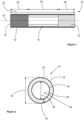
- Figure 2 shows a lateral cross-sectional view of the hollow tubular support element 14.
- the hollow tubular support element 14 comprises a peripheral wall 30 defining the tubular shape of the hollow tubular support element 14.
- the peripheral wall 30 has an external surface 32 and an interior surface 34.
- the interior surface 34 defines an inner volume 36 that forms an airflow passage 38 extending along the length 26 of the hollow tubular support element 14.
- the peripheral wall 30 has a thickness 40 of 0.71 millimetres.
- the hollow tubular support element 14 has a circular annular cross-sectional shape.
- the hollow tubular support element 14 has an external diameter 42 of 7.1 millimetres and an internal diameter 44 of 5.68 millimetres.
- Figure 3 shows a lateral cross-sectional view of an alternative arrangement of the hollow tubular support element 14.
- the hollow tubular support element 14 comprises a radial structure 46 comprising a single wall extending across the interior volume 36 defined by the peripheral wall 30.
- the radial structure 46 divides the interior volume 36 into two airflow passages 38.
- the radial structure 46 is formed integrally with the peripheral wall 30.
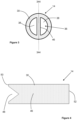
- Figure 4 shows a longitudinal cross-sectional view of the hollow tubular support element 14 of Figure 3 , taken along the line 344-344 shown in Figure 3 .
- the hollow tubular support element 14 comprises a recess 48 formed in the radial structure 46 at a first end 50 of the hollow tubular support element 14.
- the first end 50 comprising the recess 48 is positioned adjacent to the plug of aerosol-forming substrate 12.
- the recess 48 is positioned at an upstream end of the hollow tubular support element 14.
- a second end 52 of the hollow tubular support element 14 forms a downstream end of the hollow tubular support element 14.
- the recess 48 may receive a tip of a heater inserted through the plug of aerosol-forming substrate 12.
- Figure 5 shows a lateral cross-sectional view of a further alternative arrangement of the hollow tubular support element 14, similar to the arrangement shown in Figure 3 .
- the radial structure 46 is cross-shaped and divides the interior volume 36 into four airflow passages 38.
- the hollow tubular support element 14 may comprise a recess 48 in the radial structure 46, as already described with reference to Figure 4 .
- FIG 6 shows a longitudinal cross-sectional view of an aerosol-generating system 100 comprising an aerosol-generating device 102 and the aerosol-generating article 10 of Figure 1 .
- the aerosol-generating device 102 comprises a housing 104 defining a cavity 106 for receiving the aerosol-generating article 10.
- An elongate electrical heater 108 extends into the cavity 106 and is arranged for insertion into the plug of aerosol-forming substrate 12 when the aerosol-generating article 10 is inserted into the cavity 106.
- the aerosol-generating device 102 also comprises a power supply 110 and a controller 112. During use, the controller 112 controls a supply of electrical power from the power supply 110 to the elongate electrical heater 108.
- the elongate electrical heater 108 heats the plug of aerosol-forming substrate 12 to release volatile compounds from the plug of aerosol-forming substrate 12.
- the released compounds are drawn into the hollow tubular support element 14 where they cool to form an aerosol.
- the aerosol is then drawn through the filter segment 16 where they are delivered to the user.
Description
- The present invention relates to an aerosol-generating article having a hollow tubular support element positioned immediately downstream of a plug of aerosol-forming substrate and a filter segment positioned immediately downstream of the hollow tubular support element.
- Aerosol-generating articles in which an aerosol-forming substrate, such as a tobacco-containing substrate, is heated rather than combusted, are known in the art. Typically in such heated smoking articles, an aerosol is generated by the transfer of heat from a heat source to a physically separate aerosol-forming substrate or material, which may be located in contact with, within, around, or downstream of the heat source. During use of the aerosol-generating article, volatile compounds are released from the aerosol-forming substrate by heat transfer from the heat source and are entrained in air drawn through the aerosol-generating article. As the released compounds cool, they condense to form an aerosol.
- A number of prior art documents disclose aerosol-generating devices for consuming aerosol-generating articles. Such devices include, for example, electrically heated aerosol-generating devices in which an aerosol is generated by the transfer of heat from one or more electrical heater elements of the aerosol-generating device to the aerosol-forming substrate of a heated aerosol-generating article.
- It is common to include in an aerosol-generating article for producing an inhalable aerosol upon heating one or more additional elements that are assembled with the substrate in a same wrapper. Examples of such additional elements include a mouthpiece filtration segment, a support element adapted to impart structural strength to the aerosol-generating article, a cooling element adapted to favour cooling of the aerosol prior to reaching the mouthpiece, and so forth. However, although such additional elements may have several advantageous effects, their inclusion in an aerosol-generating article generally complicates the overall structure of the article and makes its manufactures more complex and less cost-effective.
-
WO 2017/198837 A1 discloses a smoking article adapted for use with an apparatus having a power source and a heater. The smoking article is in the form of a substantially cylindrical rod that includes a body of smokable material and a filter assembly in the form of a rod. The filter assembly includes a cooling segment, a filter segment and a mouth end segment. The cooling segment is located adjacent the body of smokable material between the body of smokable material and the filter segment. The filter segment is located in between the cooling segment and the mouth end segment. The mouth end segment is located towards a proximal end of the article, adjacent the filter segment. The cooling segment may be an annular tube. The body of smokable material is between 34 millimetres and 50 millimetres in length. The total length of the smoking article is between 71 millimetres and 95 millimetres. The cooling segment has a length of at least 15 millimetres and may have a length of between 20 millimetres and 30 millimetres. - It would be desirable to provide an aerosol-generating article that is more simple and cost-effective to manufacture without diminishing the function of the aerosol-generating article.
- The present invention relates to an aerosol-generating article having an upstream end and a downstream end, the aerosol-generating article defining a longitudinal direction extending between the upstream end and the downstream end, the aerosol-generating article comprising: a plug of aerosol-forming substrate at the upstream end of the aerosol-generating article; a hollow tubular support element positioned immediately downstream of the plug of aerosol-forming substrate; and a filter segment at the downstream end of the aerosol-generating article and positioned immediately downstream of the hollow tubular support element; wherein the aerosol-generating article has a length extending in the longitudinal direction between the upstream end and the downstream end; wherein the plug of aerosol-forming substrate has a length extending in the longitudinal direction between a first end of the plug of aerosol-forming substrate and a second end of the plug of aerosol-forming substrate; wherein the hollow tubular support element has a length extending in the longitudinal direction between a first end of the hollow tubular support element and a second end of the hollow tubular support element; and wherein the ratio of the length of the hollow tubular support element to the length of the aerosol-generating article is between 0.3 to 1 and 0.5 to 1. The ratio of the length of the plug of aerosol-forming substrate to the length of the hollow tubular support element is between 0.5 to 1 and 0.8 to 1.
- The term "aerosol-generating article" is used herein to describe an article comprising an aerosol-forming substrate that may be heated to produce and deliver an aerosol to a consumer. As used herein, the term "aerosol-forming substrate" denotes a substrate capable of releasing volatile compounds upon heating to generate an aerosol. During use, volatile compounds are released from the aerosol-forming substrate by heat transfer and entrained in air drawn through the aerosol-generating article. As the released compounds cool they condense to form an aerosol that is inhaled by the consumer.
- As used herein, the term "hollow tubular support element" denotes an elongate element defining a lumen or airflow passage along a longitudinal axis thereof. In the context of the present specification, the term "tubular" is intended to encompass any tubular element having a substantially cylindrical cross-section which defines at least one airflow passage establishing fluid communication between an upstream end of the tubular element and a downstream end of the tubular element.
- As used herein, the term "longitudinal" refers to the direction corresponding to the main longitudinal axis of the aerosol-generating article, which extends between the upstream and downstream ends of the aerosol-generating article. As used herein, the terms "upstream" and "downstream" describe the relative positions of elements, or portions of elements, of the aerosol-generating article in relation to the direction in which the aerosol is transported through the aerosol-generating article during use.
- During use, air is drawn through the aerosol-generating article in the longitudinal direction. The terms "transverse" and "radial" refer to the direction that is perpendicular to the longitudinal axis. Any reference to the "cross-section" of the aerosol-generating article or a component of the aerosol-generating article refers to the transverse cross-section unless stated otherwise.
- Advantageously, aerosol-generating articles according to the present invention comprise a hollow tubular support element positioned immediately downstream of a plug of aerosol-forming substrate and a filter segment positioned immediately downstream of the hollow tubular support element. In other words, the hollow tubular support element extends between the plug of aerosol-forming substrate and the filter segment. Advantageously, this simplifies the construction of the aerosol-generating article when compared to known articles in which a plurality of elements are positioned between an aerosol-forming substrate and a filter segment. Advantageously, a simplified construction facilitates a simple and cost effective manufacturing process.
- Advantageously, aerosol-generating articles according to the present invention comprise a hollow tubular support element, wherein a ratio of a length of the hollow tubular support element to a length of the aerosol-generating article is between about 0.3 to 1 and about 0.5 to 1. Advantageously, the length of the hollow tubular support element compared to the length of the aerosol-generating article is larger than known aerosol-generating articles comprising a tubular segment. Advantageously, the longer length of the hollow tubular support element makes it easier to handle the hollow tubular support element during manufacture of the aerosol-generating article. Advantageously, the longer length of the hollow tubular support element may provide the aerosol-generating article with the same amount of aerosol-cooling as known articles having a shorter tubular segment combined with an aerosol-cooling element.
- The plug of aerosol-forming substrate has a length extending in the longitudinal direction between a first end of the plug of aerosol-forming substrate and a second end of the plug of aerosol-forming substrate. The ratio of the length of the plug of aerosol-forming substrate to the length of the hollow tubular support element is between about 0.5 to 1 and about 0.8 to 1. The ratio of the length of the plug of aerosol-forming substrate to the length of the hollow tubular support element may be between about 0.5 to 1 and about 0.7 to 1. The ratio of the length of the plug of aerosol-forming substrate to the length of the hollow tubular support element may be between about 0.5 to 1 and about 0.6 to 1.
- The length of the hollow tubular support element may be less than about 50 millimetres. The length of the hollow tubular support element may be less than about 40 millimetres. The length of the hollow tubular support element may be less than about 30 millimetres. The length of the hollow tubular support element may be greater than about 14 millimetres. The length of the hollow tubular support element may be greater than about 17 millimetres. The length of the hollow tubular support element may be between about 14 millimetres and about 22 millimetres. The length of the hollow tubular support element may be between about 17 millimetres and about 22 millimetres. The length of the hollow tubular support element may be about 21 millimetres.
- The length of the plug of aerosol-forming substrate may be between about 11 millimetres and about 19 millimetres. The length of the plug of aerosol-forming substrate may be between about 11 millimetres and about 15 millimetres. The length of the plug of aerosol-forming substrate may be about 12 millimetres.
- Advantageously, a plug of aerosol-forming substrate having a length within one or more of these ranges may contain a sufficient amount of volatile compounds to facilitate the simulation of smoking a conventional cigarette.
- Advantageously, a plug of aerosol-forming substrate having a length within one or more of these ranges may reduce or minimise the required size of a heater in an aerosol-generating device for heating the article. Advantageously, this may facilitate a cost-effective manufacture of an aerosol-generating device.
- The filter segment may have a length extending in the longitudinal direction between a first end of the filter segment and a second end of the filter segment of between about 11 millimetres and about 13 millimetres. Advantageously, a filter segment having a length within this range may provide the aerosol-generating article with a desired resistance to draw. In particular, since the hollow tubular support element may have a relatively low resistance to draw, a filter segment having a length of between about 11 millimetres and about 13 millimetres may have a sufficiently high resistance to draw to provide the aerosol-generating article with a desired overall resistance to draw.
- The length of the aerosol-generating article may be between about 40 millimetres and about 100 millimetres. The length of the aerosol-generating article may be between about 40 millimetres and about 80 millimetres. The length of the aerosol-generating article may be between about 40 millimetres and about 50 millimetres. The length of the aerosol-generating article may be about 45 millimetres.
- The hollow tubular support element may comprise a polymer. The tubular support element may comprise at least one of polylactic acid, cellulose acetate, starch, poly hydroxy alkanoate, polypropylene, polyethylene, polystyrene, and combinations thereof. Preferably, the tubular support element comprises a bioplastic. Preferably, the hollow tubular support element comprises at least one of polylactic acid, cellulose acetate, starch, poly hydroxy alkanoate, and combinations thereof.
- Advantageously, forming the hollow tubular support element from a polymer may facilitate simple and cost-effective manufacture of the hollow tubular support element. For example, the hollow tubular support element may be formed by at least one of 3D-printing and injection moulding.
- Advantageously, forming the hollow tubular support element from at least one of polylactic acid and cellulose acetate may provide the hollow tubular support element with sufficient hardness to facilitate handling of the hollow tubular support element during manufacture of the aerosol-generating article.
- Advantageously, forming the hollow tubular support element from at least one of polylactic acid and cellulose acetate may provide the hollow tubular support element with a sufficient heat capacity to provide a desired aerosol-cooling function during use of the aerosol-generating article.
- Preferably, the hollow tubular support element comprises a peripheral wall defining the tubular shape of the hollow tubular support element. The peripheral wall may have a thickness of between about 0.2 millimetres and about 5 millimetres. The peripheral wall may have a thickness of less than about 2 millimetres. The peripheral wall may have a thickness of less than about 1.5 millimetres. The peripheral wall may have a thickness of less than about 1 millimetre. The peripheral wall may have a thickness of at least about 0.2 millimetres. The peripheral wall may have a thickness of at least about 0.4 millimetres. The peripheral wall may have a thickness of at least about 0.5 millimetres. The peripheral wall may have a thickness of about 0.71 millimetres.
- The term "thickness" when referring to the peripheral wall of the hollow tubular support element is used herein to refer the minimum distance measured between an outer surface and an inner surface of the peripheral wall. The distance at a given location is measured along a direction locally substantially perpendicular to the outer and inner surfaces of the peripheral wall. For a substantially cylindrical hollow tubular support element, that is, a hollow tubular support element having a substantially circular cross-section, the thickness of the peripheral wall is the distance between the outer surface and the inner surface of the peripheral wall measured along a substantially radial direction of the tubular element.
- The hollow tubular support element may have an external diameter of between about 5 millimetres and about 12 millimetres. The hollow tubular support element may have an external diameter of between about 5 millimetres and about 10 millimetres. The hollow tubular support element may have an external diameter of between about 6 millimetres and about 8 millimetres. The hollow tubular support element may have an external diameter of between about 6.5 millimetres and about 7.5 millimetres. Advantageously, a hollow tubular support element having a diameter within these ranges may facilitate forming the aerosol-generating article with an external diameter similar to a conventional cigarette. In a preferred embodiment, the hollow tubular support element has an external diameter of 7.1 mm +/- 10 percent.
- In embodiments in which the hollow tubular support element comprises a peripheral wall, the peripheral wall may define an inner volume. The hollow tubular support element may comprise a radial structure extending radially within the inner volume from at least a first point on the peripheral wall to at least a second point on the peripheral wall so that at least two airflow passages are defined by the peripheral wall and the radial structure, the at least two airflow passages extending in the longitudinal direction.
- Advantageously, the radial structure may increase the compressive strength of the hollow tubular support element in the radial direction.
- Advantageously, the radial structure may increase the internal surface area of the hollow tubular support element. Advantageously, increasing the internal surface area of the hollow tubular support element may increase the aerosol-cooling function of the hollow tubular support element.
- The cross-sectional shape of the radial structure may be cross-shaped so that the peripheral wall and the radial structure define four airflow passages extending in the longitudinal direction.
- Preferably, the radial structure is formed integrally with the peripheral wall. In other words, preferably, the radial structure and the peripheral wall are formed as a single piece. For example, the peripheral wall and the radial structure may be formed as a single piece in a 3D-printing or injection moulding process.
- The radial structure may extend along substantially the entire length of the hollow tubular support element.
- The radial structure may have a substantially constant cross-sectional shape in the longitudinal direction. The radial structure may have a substantially constant cross-sectional area in the longitudinal direction.
- The radial structure may have a rotationally symmetric cross-sectional shape. Advantageously, a rotationally symmetric cross-sectional shape may provide the at least two airflow passages with substantially the same cross-sectional areas. Advantageously, this may provide a substantially uniform airflow through the hollow tubular support element.
- Preferably, the first end of the hollow tubular support element is positioned immediately downstream of the plug of aerosol-forming substrate and the radial structure is shaped to define a recess at the first end of the hollow tubular support element, the recess extending into the inner volume defined by the peripheral wall.
- Providing a recess in the radial structure at the first end of the hollow tubular support element may be particularly advantageous in embodiments in which a heater is inserted into the aerosol-forming substrate to heat the aerosol-forming substrate. For example, the aerosol-generating article may be inserted into an aerosol-generating device comprise an elongate heater that is inserted into the aerosol-forming substrate from the upstream end of the aerosol-generating article. Advantageously, the recess in the radial structure may be arranged to receive a tip of the elongate heater. Advantageously, receiving a tip of the elongate heater in the recess in the radial structure may facilitate insertion of the elongate heater through the entire length of the aerosol-forming substrate in the longitudinal direction. Advantageously, the recess in the radial structure may receive the tip of the elongate heater without the need for direct contact between the elongate heater and the hollow tubular support element. Advantageously, preventing direct contact between the heater and the hollow tubular support element may prevent melting of the hollow tubular support element during heating of the aerosol-forming substrate.
- Providing a recess in the radial structure at the first end of the hollow tubular support element may be particularly advantageous in embodiments in which the aerosol-generating article comprises a heating element received within the aerosol-forming substrate. For example, the aerosol-generating article may comprise a susceptor positioned within the aerosol-forming substrate. The susceptor may function as a heating element to heat the aerosol-forming substrate when the susceptor is inductively heated. Advantageously, the recess in the radial structure may receive an end of the heating element. Advantageously, positioning an end of the heating element in the recess in the radial structure may facilitate a heating element that extends through the entire length of the aerosol-forming substrate in the longitudinal direction. Advantageously, the recess in the radial structure may receive the end of the heating element without the need for direct contact between the heating element and the hollow tubular support element. Advantageously, preventing direct contact between the heating element and the hollow tubular support element may prevent melting of the hollow tubular support element during heating of the aerosol-forming substrate.
- Preferably, the aerosol-generating article comprises an outer wrapper wrapped around the plug of aerosol-forming substrate, the hollow tubular support element, and the filter segment. Preferably, the wrapper is a paper wrapper.
- Preferably, the filter segment is in the form of a plug. Preferably, the filter segment comprise fibres. Preferably, the fibres of the filter segment comprise cellulose acetate.
- Preferably, the aerosol-forming substrate comprises plant material and an aerosol former. Preferably, the plant material is a plant material comprising an alkaloid, more preferably a plant material comprising nicotine, and more preferably a tobacco-containing material.
- Preferably, the aerosol-forming substrate comprises at least 70 percent of plant material, more preferably at least 90 percent of plant material by weight on a dry weight basis. Preferably, the aerosol-forming substrate comprises less than 95 percent of plant material by weight on a dry weight basis, such as from 90 to 95 percent of plant material by weight on a dry weight basis.
- Preferably, the aerosol-forming substrate comprises at least 5 percent of aerosol former, more preferably at least 10 percent of aerosol former by weight on a dry weight basis. Preferably, the aerosol-forming substrate comprises less than 30 percent of aerosol former by weight on a dry weight basis, such as from 5 to 30 percent of aerosol former by weight on a dry weight basis.
- In some particularly preferred embodiments, the aerosol-forming substrate comprises plant material and an aerosol former, wherein the substrate has an aerosol former content of between 5 percent and 30 percent by weight on a dry weight basis. The plant material is preferably a plant material comprising an alkaloid, more preferably a plant material comprising nicotine, and more preferably a tobacco-containing material. Alkaloids are a class of naturally occurring nitrogen-containing organic compounds. Alkaloids are found mostly in plants, but are also found in bacteria, fungi and animals. Examples of alkaloids include, but are not limited to, caffeine, nicotine, theobromine, atropine and tubocurarine. A preferred alkaloid is nicotine, which may be found in tobacco.
- An aerosol-forming substrate may comprise nicotine. An aerosol-forming substrate may comprise tobacco, for example may comprise a tobacco-containing material containing volatile tobacco flavour compounds, which are released from the aerosol-forming substrate upon heating. In preferred embodiments an aerosol-forming substrate may comprise homogenised tobacco material, for example cast leaf tobacco. The aerosol-forming substrate may comprise both solid and liquid components. The aerosol-forming substrate may comprise a tobacco-containing material containing volatile tobacco flavour compounds, which are released from the substrate upon heating. The aerosol-forming substrate may comprise a non-tobacco material. The aerosol-forming substrate may further comprise an aerosol former. Examples of suitable aerosol formers are glycerine and propylene glycol.
- In some preferred embodiments, the aerosol-forming substrate may comprise a textured sheet of homogenised tobacco material with an aerosol former content of between 5% and 30% by weight on a dry weight basis. Use of a textured sheet of homogenised tobacco material may advantageously facilitate gathering of the sheet of homogenised tobacco material to form the aerosol-forming substrate.
- As used herein, the term 'crimped sheet' denotes a sheet having a plurality of substantially parallel ridges or corrugations. Preferably, when the aerosol-generating article has been assembled, the substantially parallel ridges or corrugations extend along or parallel to the longitudinal axis of the aerosol-generating article. This advantageously facilitates gathering of the crimped sheet of homogenised tobacco material to form the aerosol-forming substrate. However, it will be appreciated that crimped sheets of homogenised tobacco material for inclusion in the aerosol-generating article may alternatively or in addition have a plurality of substantially parallel ridges or corrugations that are disposed at an acute or obtuse angle to the longitudinal axis of the aerosol-generating article when the aerosol-generating article has been assembled.
- The aerosol-forming substrate may be in the form of a plug comprising an aerosol-forming material circumscribed by a paper or other wrapper. Where an aerosol-forming substrate is in the form of a plug, the entire plug including any wrapper is considered to be the aerosol-forming substrate.
- The aerosol-forming substrate of the present invention preferably comprises an aerosol former. As used herein, the term 'aerosol former' is used to describe any suitable known compound or mixture of compounds that, in use, facilitates formation of an aerosol and that is substantially resistant to thermal degradation at the operating temperature of the aerosol-generating article.
- Suitable aerosol-formers are known in the art and include, but are not limited to: polyhydric alcohols, such as propylene glycol, triethylene glycol, 1,3-butanediol and glycerine; esters of polyhydric alcohols, such as glycerol mono-, di- or triacetate; and aliphatic esters of mono-, di- or polycarboxylic acids, such as dimethyl dodecanedioate and dimethyl tetradecanedioate. Preferred aerosol formers are polyhydric alcohols or mixtures thereof, such as propylene glycol, triethylene glycol, 1 ,3-butanediol and, most preferred, glycerine.
- The aerosol-forming substrate may comprise a single aerosol former. Alternatively, the aerosol-forming substrate may comprise a combination of two or more aerosol formers.
- Preferably, the aerosol-forming substrate is in the form of a rod comprising a gathered sheet of aerosol-forming material, for example a gathered sheet of homogenised tobacco, or a gathered sheet comprising a nicotine salt and an aerosol former.
- Aerosol-forming substrates comprising gathered sheets of homogenised tobacco for use in the aerosol-generating article may be made by methods known in the art, for example the methods disclosed in
WO 2012/164009 A2 . - Preferably, the aerosol-forming substrate has an external diameter of at least 5 millimetres. The aerosol-forming substrate may have an external diameter of between approximately 5 millimetres and approximately 12 millimetres, for example of between approximately 5 millimetres and approximately 10 millimetres or of between approximately 6 millimetres and approximately 8 millimetres. In a preferred embodiment, the aerosol-forming substrate has an external diameter of 7.2 millimetres +/- 10 percent.
- The aerosol-forming substrate may have a length of between approximately 5 millimetres and approximately 15 millimetres, for example between about 8 millimetres and about 12 millimetres. In one embodiment, the aerosol-forming substrate may have a length of approximately 10 millimetres. In a preferred embodiment, the aerosol-forming substrate has a length of approximately 12 millimetres. Preferably, the aerosol-forming substrate is substantially cylindrical.
- According to a second aspect of the present invention there is provided an aerosol-generating system comprising and aerosol-generating device and an aerosol-generating article according to the first aspect of the present invention in accordance with any of the embodiments described herein. The aerosol-generating device comprises a cavity arranged to receive at least a portion of the aerosol-generating article and a heater positioned to heat the plug of aerosol-forming substrate when the aerosol-generating article is received within the cavity.
- As used herein, the term "aerosol generating device" refers to a device comprising a heater that interacts with the aerosol-forming substrate of the aerosol-generating article to generate an aerosol.
- The heater may be positioned within the cavity and arranged for insertion into the plug of aerosol-forming substrate when the aerosol-generating article is received within the cavity. The heater may extend into the cavity.
- The heater may be arranged to extend around an outer surface of the aerosol-generating article when the aerosol-generating article is received within the cavity.
- Preferably, the heater is an electrical heater.
- The electrical heater may extend into the cavity. The electrical heater may be an elongate electrical heater. The elongate electrical heater may comprise a distal end arranged to be received within an aerosol-generating article and a proximal end opposite the distal end. The electrical heater may be blade-shaped. The electrical heater may be pin-shaped. The electrical heater may be cone-shaped.
- The elongate electrical heater may comprise at least one resistive heating track. The at least one resistive heating track may be surrounded by an electrically insulating substrate. The at least one resistive heating track may be embedded within an electrically insulating substrate. The electrically insulating substrate may comprise a ceramic. The electrically insulating substrate may be received within a tubular shell. The tubular shell may comprise at least one metal.
- The electrical heater may comprise a resistive heating element. During use, an electrical current is supplied to the resistive heating element to generate heat by resistive heating.
- Suitable materials for forming the resistive heating element include but are not limited to: semiconductors such as doped ceramics, electrically "conductive" ceramics (such as, for example, molybdenum disilicide), carbon, graphite, metals, metal alloys and composite materials made of a ceramic material and a metallic material. Such composite materials may comprise doped or undoped ceramics. Examples of suitable doped ceramics include doped silicon carbides. Examples of suitable metals include titanium, zirconium, tantalum and metals from the platinum group. Examples of suitable metal alloys include stainless steel, nickel-, cobalt-, chromium-, aluminium- titanium- zirconium-, hafnium-, niobium-, molybdenum-, tantalum-, tungsten-, tin-, gallium-, manganese- and iron-containing alloys, and super-alloys based on nickel, iron, cobalt, stainless steel, Timetal® and iron-manganese-aluminium based alloys.
- In some embodiments, the resistive heating element comprises one or more stamped portions of electrically resistive material, such as stainless steel. Alternatively, the resistive heating element may comprise a heating wire or filament, for example a Ni-Cr (Nickel-Chromium), platinum, tungsten or alloy wire.
- The electrical heater may comprise an electrically insulating substrate, wherein the resistive heating element is provided on the electrically insulating substrate. The electrically insulating substrate may be a ceramic material such as Zirconia or Alumina. Preferably, the electrically insulating substrate has a thermal conductivity of less than or equal to about 2 Watts per metre Kelvin.
- The electrical heater may be arranged to extend around an outer surface of an aerosol-generating article received within the cavity. The electrical heater may have a tubular shape. The electrical heater may comprise an electrically insulating substrate and at least one resistive heating track on the electrically insulating substrate. The electrically insulating substrate may comprise a flexible sheet. Advantageously, a flexible sheet may facilitate manufacturing the electrical heater in a flat state and subsequently deforming the flexible sheet into a desired shape. For example, the electrical heater may be formed in a flat state and then rolled into a tubular shape. The electrically insulating substrate may comprise a polyimide film. The at least one resistive heating track may comprise at least one metal. The at least one resistive heating track may comprise a metal. The at least one resistive heating track may comprise a metal alloy. Examples of suitable metals include titanium, zirconium, tantalum and metals from the platinum group. Examples of suitable metal alloys include stainless steel, nickel-, cobalt-, chromium-, aluminium- titanium- zirconium-, hafnium-, niobium-, molybdenum-, tantalum-, tungsten-, tin-, gallium-, manganese- and iron-containing alloys, and super-alloys based on nickel, iron, cobalt, stainless steel, Timetal® and iron-manganese-aluminium based alloys.
- The at least one resistive heating track may define a plurality of heating zones.
- The at least one resistive heating track may comprise a plurality of heating tracks. The plurality of heating tracks may define a plurality of heating zones.
- The at least one resistive heating track may comprise a single heating track comprising a plurality of portions, wherein each portion defines a heating zone.
- Advantageously, at least some of the heating zones may be heated to different temperature during use. Advantageously, at least some of the heating zones may be heated at different times during use. Each heating zone may be defined by a single resistive heating track. Each heating zone may be defined by a plurality of resistive heating tracks.
- The electrical heater may comprise an inductive heating element. During use, the inductive heating element inductively heats a susceptor material to heat the aerosol-generating article when the aerosol-generating article is received within the cavity. The susceptor material may form part of the aerosol-generating device. The susceptor material may form part of the aerosol-generating article.
- Preferably, the aerosol-generating device comprises a power supply and a controller arranged to supply power from the power supply to the electrical heater during use of the aerosol-generating device.
- Preferably, the controller is arranged to supply power from the power supply to the electrical heater according to a predetermined heating cycle when the aerosol-generating device is used to heat the aerosol-generating article received within the cavity.
- The power supply may be a DC voltage source. In preferred embodiments, the power supply is a battery. For example, the power supply may be a nickel-metal hydride battery, a nickel cadmium battery, or a lithium based battery, for example a lithium-cobalt, a lithium-iron-phosphate or a lithium-polymer battery. The power supply may alternatively be another form of charge storage device such as a capacitor. The power supply may require recharging and may have a capacity that allows for the storage of enough energy for use of the aerosol-generating device with one or more aerosol-generating articles.
- Preferably, the aerosol-generating device comprises at least one air inlet. Preferably, the at least one air inlet is in fluid communication with an upstream end of the cavity. In embodiments in which the aerosol-generating device comprises an elongate electrical heater, preferably the elongate electrical heater extends into the cavity from the upstream end of the cavity.
- The aerosol-generating device may comprise a sensor to detect air flow indicative of a user taking a puff. The air flow sensor may be an electro-mechanical device. The air flow sensor may be any of: a mechanical device, an optical device, an opto-mechanical device and a micro electro-mechanical systems (MEMS) based sensor. The aerosol-generating device may comprise a manually operable switch for a user to initiate a puff.
- The aerosol-generating device may comprise a temperature sensor. The temperature sensor may be mounted on the printed circuit board. In embodiments in which the aerosol-generating device comprises an electrical heater, the temperature sensor may be mounted on the electrical heater. In embodiments in which the electrical heater comprises an electrically insulating substrate, the temperature sensor may be mounted on the electrically insulating substrate. In embodiments in which the electrical heater is an elongate electrical heater, the temperature sensor may be mounted on the distal end of the elongate electrical heater.
- The temperature sensor may detect the temperature of the electrical heater or the temperature of the aerosol-generating article received within the cavity. The temperature sensor may be a thermistor. The temperature sensor may be a thermocouple. The temperature sensor may comprise a circuit configured to measure the resistivity of the electrical heater and derive a temperature of the electrical heater by comparing the measured resistivity to a calibrated curve of resistivity against temperature.
- Advantageously, deriving the temperature of the electrical heater may facilitate control of the temperature to which the electrical heater is heated during use. The controller may be configured to adjust the supply of power to the electrical heater in response to a change in the measured resistivity of the electrical heater.
- Advantageously, deriving the temperature of the electrical heater may facilitate puff detection. For example, a measured drop in the temperature of the electrical heater may correspond to a user puffing or drawing on the aerosol-generating article.
- It will be appreciated that any features described with reference to one aspect of the present invention are equally applicable to any other aspect of the invention.
- The invention will now be further described, by way of example only, with reference to the accompanying drawings in which:
-
Figure 1 shows a longitudinal cross-sectional view of an aerosol-generating article in accordance with an embodiment of the present invention; -
Figure 2 shows a transverse cross-sectional view of the hollow tubular support element of the aerosol-generating article ofFigure 1 ; -
Figure 3 shows a transverse cross-sectional view of an alternative arrangement of the hollow tubular support element of the aerosol-generating article ofFigure 1 ; -
Figure 4 shows a longitudinal cross-sectional view of the hollow tubular support element ofFigure 3 ; -
Figure 5 shows a transverse cross-sectional view of a further alternative arrangement of the hollow tubular support element of the aerosol-generating article ofFigure 1 ; and -
Figure 6 shows a longitudinal cross-sectional view of an aerosol-generating system comprising the aerosol-generating article ofFigure 1 . -
Figure 1 shows an aerosol-generatingarticle 10 according to an embodiment of the present invention. The aerosol-generatingarticle 10 comprises a plug of aerosol-formingsubstrate 12 comprising tobacco and positioned at an upstream end of the aerosol-generatingarticle 10. Positioned immediately downstream of the plug of aerosol-formingsubstrate 12 is a hollowtubular support element 14 formed of polylactic acid. Positioned immediately downstream of the hollowtubular support element 14 and at a downstream end of the aerosol-generatingarticle 10 is afilter segment 16 comprising fibres of cellulose acetate. The aerosol-generatingarticle 10 also comprises anouter wrapper 18 formed of paper and circumscribing the plug of aerosol-formingsubstrate 12, the hollowtubular support element 14 and thefilter segment 16. - The aerosol-generating
article 10 defines alongitudinal direction 20 and has alength 22 extending between the upstream and downstream ends of the aerosol-generatingarticle 10. Thelength 22 of the aerosol-generatingarticle 10 is 45 millimetres. - The plug of aerosol-forming
substrate 12, the hollowtubular support element 14 and thefilter segment 16 each have alength length 24 of the plug of aerosol-formingsubstrate 12 is 12 millimetres. Thelength 26 of the hollowtubular support element 14 is 21 millimetres. Thelength 28 of thefilter segment 18 is 12 millimetres. The ratio of thelength 26 of the hollowtubular support element 14 to thelength 22 of the aerosol-generatingarticle 10 is 0.47 to 1. -
Figure 2 shows a lateral cross-sectional view of the hollowtubular support element 14. The hollowtubular support element 14 comprises aperipheral wall 30 defining the tubular shape of the hollowtubular support element 14. Theperipheral wall 30 has anexternal surface 32 and aninterior surface 34. Theinterior surface 34 defines aninner volume 36 that forms anairflow passage 38 extending along thelength 26 of the hollowtubular support element 14. Theperipheral wall 30 has athickness 40 of 0.71 millimetres. The hollowtubular support element 14 has a circular annular cross-sectional shape. The hollowtubular support element 14 has anexternal diameter 42 of 7.1 millimetres and aninternal diameter 44 of 5.68 millimetres. -
Figure 3 shows a lateral cross-sectional view of an alternative arrangement of the hollowtubular support element 14. In the arrangement shown inFigure 3 , the hollowtubular support element 14 comprises aradial structure 46 comprising a single wall extending across theinterior volume 36 defined by theperipheral wall 30. Theradial structure 46 divides theinterior volume 36 into twoairflow passages 38. Theradial structure 46 is formed integrally with theperipheral wall 30. -
Figure 4 shows a longitudinal cross-sectional view of the hollowtubular support element 14 ofFigure 3 , taken along the line 344-344 shown inFigure 3 . The hollowtubular support element 14 comprises arecess 48 formed in theradial structure 46 at afirst end 50 of the hollowtubular support element 14. When the hollowtubular support element 14 is assembled with the plug of aerosol-formingsubstrate 12 and thefilter segment 16 to form the aerosol-generatingarticle 10, thefirst end 50 comprising therecess 48 is positioned adjacent to the plug of aerosol-formingsubstrate 12. In other words, therecess 48 is positioned at an upstream end of the hollowtubular support element 14. Asecond end 52 of the hollowtubular support element 14 forms a downstream end of the hollowtubular support element 14. During use of the aerosol-generatingarticle 10 in an aerosol-generating device, therecess 48 may receive a tip of a heater inserted through the plug of aerosol-formingsubstrate 12. -
Figure 5 shows a lateral cross-sectional view of a further alternative arrangement of the hollowtubular support element 14, similar to the arrangement shown inFigure 3 . In the arrangement shown inFigure 5 , theradial structure 46 is cross-shaped and divides theinterior volume 36 into fourairflow passages 38. The hollowtubular support element 14 may comprise arecess 48 in theradial structure 46, as already described with reference toFigure 4 . -
Figure 6 shows a longitudinal cross-sectional view of an aerosol-generatingsystem 100 comprising an aerosol-generatingdevice 102 and the aerosol-generatingarticle 10 ofFigure 1 . The aerosol-generatingdevice 102 comprises ahousing 104 defining acavity 106 for receiving the aerosol-generatingarticle 10. An elongateelectrical heater 108 extends into thecavity 106 and is arranged for insertion into the plug of aerosol-formingsubstrate 12 when the aerosol-generatingarticle 10 is inserted into thecavity 106. The aerosol-generatingdevice 102 also comprises apower supply 110 and acontroller 112. During use, thecontroller 112 controls a supply of electrical power from thepower supply 110 to the elongateelectrical heater 108. The elongateelectrical heater 108 heats the plug of aerosol-formingsubstrate 12 to release volatile compounds from the plug of aerosol-formingsubstrate 12. When a user draws on thefilter segment 16, the released compounds are drawn into the hollowtubular support element 14 where they cool to form an aerosol. The aerosol is then drawn through thefilter segment 16 where they are delivered to the user.
Claims (14)
- An aerosol-generating article (10) having an upstream end and a downstream end, the aerosol-generating article (10) defining a longitudinal direction (20) extending between the upstream end and the downstream end, the aerosol-generating article (10) comprising:a plug of aerosol-forming substrate (12) at the upstream end of the aerosol-generating article (10);a hollow tubular support element (14) positioned immediately downstream of the plug of aerosol-forming substrate (12); anda filter segment (16) at the downstream end of the aerosol-generating article (10) and positioned immediately downstream of the hollow tubular support element (14);wherein the aerosol-generating article (10) has a length (22) extending in the longitudinal direction between the upstream end and the downstream end;wherein the plug of aerosol-forming substrate (12) has a length (24) extending in the longitudinal direction (20) between a first end of the plug of aerosol-forming substrate (12) and a second end of the plug of aerosol-forming substrate (12);wherein the hollow tubular support element (14) has a length (26) extending in the longitudinal direction (20) between a first end of the hollow tubular support element (14) and a second end of the hollow tubular support element (14);wherein the ratio of the length (26) of the hollow tubular support element (14) to the length (22) of the aerosol-generating article (10) is between 0.3 to 1 and 0.5 to 1; andwherein the ratio of the length (24) of the plug of aerosol-forming substrate (12) to the length (26) of the hollow tubular support element (14) is between 0.5 to 1 and 0.8 to 1.
- An aerosol-generating article (10) according to claim 1, wherein the length (26) of the hollow tubular support element (14) is between 14 millimetres and 22 millimetres.
- An aerosol-generating article (10) according to claim 1 or 2, wherein the length (24) of the plug of aerosol-forming substrate (12) is between 11 millimetres and 19 millimetres.
- An aerosol-generating article (10) according to any preceding claim, wherein the filter segment (16) has a length (28) extending in the longitudinal direction (20) between a first end of the filter segment (16) and a second end of the filter segment (16) of between 11 millimetres and 13 millimetres.
- An aerosol-generating article (10) according to any preceding claim, wherein length (22) of the aerosol-generating article (10) is between 40 millimetres and 50 millimetres.
- An aerosol-generating article (10) according to any preceding claim, wherein the hollow tubular support element (14) comprises a polymer, preferably at least one of polylactic acid, cellulose acetate, starch, and poly hydroxy alkanoate.
- An aerosol-generating article (10) according to any preceding claim, wherein the hollow tubular support element (14) has an external diameter (42) of between 6 millimetres and 8 millimetres.
- An aerosol-generating article (10) according to any preceding claim, wherein the hollow tubular support element (14) comprises a peripheral wall (30) defining the tubular shape of the hollow tubular support element (14), the peripheral wall (30) having a thickness (40) of between 0.5 millimetres and 1 millimetre.
- An aerosol-generating article (10) according to any preceding claim, wherein the hollow tubular support element (14) comprises:a peripheral wall (30) defining the tubular shape of the hollow tubular support element (14), the peripheral wall (30) defining an inner volume (36); anda radial structure (46) extending radially within the inner volume (36) from at least a first point on the peripheral wall (30) to at least a second point on the peripheral wall (30) so that at least two airflow passages (38) are defined by the peripheral wall (30) and the radial structure (46), the at least two airflow passages (38) extending in the longitudinal direction (20).
- An aerosol-generating article (10) according to claim 9, wherein a cross-sectional shape of the radial structure (46) is cross-shaped so that the peripheral wall (30) and the radial structure (46) define four airflow passages (38) extending in the longitudinal direction (20).
- An aerosol-generating article (10) according to claim 9 or 10, wherein the first end of the hollow tubular support element (14) is positioned immediately downstream of the plug of aerosol-forming substrate (12), and wherein the radial structure (46) is shaped to define a recess (48) at the first end of the hollow tubular support element (14), the recess (48) extending into the inner volume (36) defined by the peripheral wall (30).
- An aerosol-generating article (10) according to any preceding claim, further comprising an outer wrapper (18) wrapped around the plug of aerosol-forming substrate (12), the hollow tubular support element (14), and the filter segment (16).
- An aerosol-generating system (100) comprising:aerosol-generating article (10) according to any preceding claim; andan aerosol-generating device (102) comprising a cavity (106) arranged to receive at least a portion of the aerosol-generating article (10) and a heater (108) positioned to heat the plug of aerosol-forming substrate (12) when the aerosol-generating article (10) is received within the cavity (106).
- An aerosol-generating system (100) according to claim 13, wherein the heater (108) is positioned within the cavity (106) and arranged for insertion into the plug of aerosol-forming substrate (12) when the aerosol-generating article (10) is received within the cavity (106).
Applications Claiming Priority (2)
| Application Number | Priority Date | Filing Date | Title |
|---|---|---|---|
| EP19167434 | 2019-04-04 | ||
| PCT/EP2020/057660 WO2020200820A1 (en) | 2019-04-04 | 2020-03-19 | Aerosol-generating article having a tubular support element |
Publications (2)
| Publication Number | Publication Date |
|---|---|
| EP3945873A1 EP3945873A1 (en) | 2022-02-09 |
| EP3945873B1 true EP3945873B1 (en) | 2023-05-03 |
Family
ID=66101854
Family Applications (1)
| Application Number | Title | Priority Date | Filing Date |
|---|---|---|---|
| EP20712953.7A Active EP3945873B1 (en) | 2019-04-04 | 2020-03-19 | Aerosol-generating article having a tubular support element |
Country Status (10)
| Country | Link |
|---|---|
| US (1) | US20220175022A1 (en) |
| EP (1) | EP3945873B1 (en) |
| JP (1) | JP2022526272A (en) |
| KR (1) | KR20210146940A (en) |
| CN (1) | CN113613516A (en) |
| BR (1) | BR112021017417A2 (en) |
| ES (1) | ES2946407T3 (en) |
| MX (1) | MX2021012084A (en) |
| PL (1) | PL3945873T3 (en) |
| WO (1) | WO2020200820A1 (en) |
Families Citing this family (7)
| Publication number | Priority date | Publication date | Assignee | Title |
|---|---|---|---|---|
| JP6890864B2 (en) * | 2018-05-17 | 2021-06-18 | 株式会社東亜産業 | Fragrance cartridge |
| CN109007984A (en) * | 2018-09-17 | 2018-12-18 | 深圳市合元科技有限公司 | Calandria and heater |
| KR20210050569A (en) * | 2018-12-06 | 2021-05-07 | 필립모리스 프로덕츠 에스.에이. | Aerosol-generating article with narrow hollow tubular filter |
| PL3945910T3 (en) * | 2019-04-04 | 2023-10-02 | Philip Morris Products S.A. | Aerosol-generating article comprising a hollow tubular support element |
| CN116709939A (en) * | 2020-12-18 | 2023-09-05 | 菲利普莫里斯生产公司 | Aerosol-generating article with hollow tubular element |
| KR20230122070A (en) * | 2020-12-18 | 2023-08-22 | 필립모리스 프로덕츠 에스.에이. | Aerosol-generating articles having hollow tubular elements |
| WO2022188119A1 (en) * | 2021-03-12 | 2022-09-15 | Huawei Technologies Co., Ltd. | Method and system for wlan multi-link management frame addressing |
Citations (1)
| Publication number | Priority date | Publication date | Assignee | Title |
|---|---|---|---|---|
| CN107536115A (en) * | 2017-09-26 | 2018-01-05 | 南通鑫源实业有限公司 | A kind of heating without smoking material is not burnt Cigarette |
Family Cites Families (12)
| Publication number | Priority date | Publication date | Assignee | Title |
|---|---|---|---|---|
| US9930910B2 (en) | 2011-05-31 | 2018-04-03 | Philip Morris Products S.A. | Rods for use in smoking articles |
| AR089602A1 (en) * | 2011-12-30 | 2014-09-03 | Philip Morris Products Sa | AEROSOL GENERATOR ARTICLE FOR USE WITH AN AEROSOL GENERATOR DEVICE |
| MX347010B (en) * | 2012-06-07 | 2017-04-06 | Philip Morris Products Sa | Smoking article having high density tobacco. |
| HUE029759T2 (en) * | 2012-12-28 | 2017-04-28 | Philip Morris Products Sa | Heating assembly for an aerosol generating system |
| TW201703660A (en) * | 2015-06-23 | 2017-02-01 | 菲利浦莫里斯製品股份有限公司 | Aerosol-generating article and method for manufacturing aerosol-generating articles |
| JP6918800B2 (en) * | 2015-12-31 | 2021-08-11 | フィリップ・モーリス・プロダクツ・ソシエテ・アノニム | Fragile aerosol-generating articles |
| TW201731397A (en) * | 2016-02-29 | 2017-09-16 | 菲利浦莫里斯製品股份有限公司 | Smoking article having filter with hollow tube segment |
| BR112018067767B1 (en) * | 2016-03-09 | 2023-03-07 | Philip Morris Products S.A. | AEROSOL GENERATOR ARTICLE |
| GB201608928D0 (en) * | 2016-05-20 | 2016-07-06 | British American Tobacco Co | Article for use in apparatus for heating smokable material |
| US10952472B2 (en) * | 2016-05-31 | 2021-03-23 | Altria Client Services Llc | Heat diffuser for an aerosol-generating system |
| CN207604513U (en) * | 2016-12-16 | 2018-07-13 | 韩国烟草人参公社 | Aerosol product product |
| CN108113051B (en) * | 2017-12-07 | 2019-03-12 | 共青城道乐投资管理合伙企业(有限合伙) | Cigarette filter is not burnt in a kind of heating and heating is not burnt cigarette |
-
2020
- 2020-03-19 ES ES20712953T patent/ES2946407T3/en active Active
- 2020-03-19 KR KR1020217031852A patent/KR20210146940A/en unknown
- 2020-03-19 MX MX2021012084A patent/MX2021012084A/en unknown
- 2020-03-19 BR BR112021017417A patent/BR112021017417A2/en unknown
- 2020-03-19 JP JP2021555538A patent/JP2022526272A/en active Pending
- 2020-03-19 PL PL20712953.7T patent/PL3945873T3/en unknown
- 2020-03-19 WO PCT/EP2020/057660 patent/WO2020200820A1/en unknown
- 2020-03-19 US US17/600,694 patent/US20220175022A1/en active Pending
- 2020-03-19 EP EP20712953.7A patent/EP3945873B1/en active Active
- 2020-03-19 CN CN202080020154.0A patent/CN113613516A/en active Pending
Patent Citations (1)
| Publication number | Priority date | Publication date | Assignee | Title |
|---|---|---|---|---|
| CN107536115A (en) * | 2017-09-26 | 2018-01-05 | 南通鑫源实业有限公司 | A kind of heating without smoking material is not burnt Cigarette |
Also Published As
| Publication number | Publication date |
|---|---|
| US20220175022A1 (en) | 2022-06-09 |
| MX2021012084A (en) | 2021-11-03 |
| WO2020200820A1 (en) | 2020-10-08 |
| PL3945873T3 (en) | 2023-08-07 |
| ES2946407T3 (en) | 2023-07-18 |
| BR112021017417A2 (en) | 2022-02-01 |
| KR20210146940A (en) | 2021-12-06 |
| JP2022526272A (en) | 2022-05-24 |
| EP3945873A1 (en) | 2022-02-09 |
| CN113613516A (en) | 2021-11-05 |
Similar Documents
| Publication | Publication Date | Title |
|---|---|---|
| EP3945873B1 (en) | Aerosol-generating article having a tubular support element | |
| US20210186105A1 (en) | Electrically heated smoking system having a liquid storage portion | |
| US20230113967A1 (en) | Heater for an electrically heated aerosol generating system | |
| EP3664642B1 (en) | Aerosol-generating device having an inductor coil with reduced separation | |
| EP3250059B1 (en) | Aerosol-generating article with integral heating element | |
| US11140923B2 (en) | Inductive heating arrangement comprising a temperature sensor | |
| EP3406148A1 (en) | Aerosol-forming article comprising magnetic particles | |
| WO2019021119A1 (en) | Heat transfer adaptor for aerosol generating device | |
| KR102503841B1 (en) | Aerosol generating device comprising heating element and aerosol generating system | |
| RU2810158C2 (en) | Aerosol-generating product having tubular supporting element and system for aerosol generation | |
| EP4322775A1 (en) | Aerosol-generating article comprising a dual-layer wrapping structure |
Legal Events
| Date | Code | Title | Description |
|---|---|---|---|
| STAA | Information on the status of an ep patent application or granted ep patent |
Free format text: STATUS: UNKNOWN |
|
| STAA | Information on the status of an ep patent application or granted ep patent |
Free format text: STATUS: THE INTERNATIONAL PUBLICATION HAS BEEN MADE |
|
| PUAI | Public reference made under article 153(3) epc to a published international application that has entered the european phase |
Free format text: ORIGINAL CODE: 0009012 |
|
| STAA | Information on the status of an ep patent application or granted ep patent |
Free format text: STATUS: REQUEST FOR EXAMINATION WAS MADE |
|
| 17P | Request for examination filed |
Effective date: 20211001 |
|
| AK | Designated contracting states |
Kind code of ref document: A1 Designated state(s): AL AT BE BG CH CY CZ DE DK EE ES FI FR GB GR HR HU IE IS IT LI LT LU LV MC MK MT NL NO PL PT RO RS SE SI SK SM TR |
|
| DAV | Request for validation of the european patent (deleted) | ||
| DAX | Request for extension of the european patent (deleted) | ||
| GRAP | Despatch of communication of intention to grant a patent |
Free format text: ORIGINAL CODE: EPIDOSNIGR1 |
|
| STAA | Information on the status of an ep patent application or granted ep patent |
Free format text: STATUS: GRANT OF PATENT IS INTENDED |
|
| INTG | Intention to grant announced |
Effective date: 20221025 |
|
| GRAS | Grant fee paid |
Free format text: ORIGINAL CODE: EPIDOSNIGR3 |
|
| GRAA | (expected) grant |
Free format text: ORIGINAL CODE: 0009210 |
|
| STAA | Information on the status of an ep patent application or granted ep patent |
Free format text: STATUS: THE PATENT HAS BEEN GRANTED |
|
| AK | Designated contracting states |
Kind code of ref document: B1 Designated state(s): AL AT BE BG CH CY CZ DE DK EE ES FI FR GB GR HR HU IE IS IT LI LT LU LV MC MK MT NL NO PL PT RO RS SE SI SK SM TR |
|
| REG | Reference to a national code |
Ref country code: GB Ref legal event code: FG4D |
|
| REG | Reference to a national code |
Ref country code: DE Ref legal event code: R096 Ref document number: 602020010422 Country of ref document: DE |
|
| REG | Reference to a national code |
Ref country code: AT Ref legal event code: REF Ref document number: 1563839 Country of ref document: AT Kind code of ref document: T Effective date: 20230515 Ref country code: CH Ref legal event code: EP |
|
| REG | Reference to a national code |
Ref country code: IE Ref legal event code: FG4D |
|
| REG | Reference to a national code |
Ref country code: NL Ref legal event code: FP |
|
| P01 | Opt-out of the competence of the unified patent court (upc) registered |
Effective date: 20230529 |
|
| REG | Reference to a national code |
Ref country code: ES Ref legal event code: FG2A Ref document number: 2946407 Country of ref document: ES Kind code of ref document: T3 Effective date: 20230718 |
|
| REG | Reference to a national code |
Ref country code: LT Ref legal event code: MG9D |
|
| REG | Reference to a national code |
Ref country code: AT Ref legal event code: MK05 Ref document number: 1563839 Country of ref document: AT Kind code of ref document: T Effective date: 20230503 |
|
| PG25 | Lapsed in a contracting state [announced via postgrant information from national office to epo] |
Ref country code: SE Free format text: LAPSE BECAUSE OF FAILURE TO SUBMIT A TRANSLATION OF THE DESCRIPTION OR TO PAY THE FEE WITHIN THE PRESCRIBED TIME-LIMIT Effective date: 20230503 Ref country code: PT Free format text: LAPSE BECAUSE OF FAILURE TO SUBMIT A TRANSLATION OF THE DESCRIPTION OR TO PAY THE FEE WITHIN THE PRESCRIBED TIME-LIMIT Effective date: 20230904 Ref country code: NO Free format text: LAPSE BECAUSE OF FAILURE TO SUBMIT A TRANSLATION OF THE DESCRIPTION OR TO PAY THE FEE WITHIN THE PRESCRIBED TIME-LIMIT Effective date: 20230803 Ref country code: AT Free format text: LAPSE BECAUSE OF FAILURE TO SUBMIT A TRANSLATION OF THE DESCRIPTION OR TO PAY THE FEE WITHIN THE PRESCRIBED TIME-LIMIT Effective date: 20230503 |
|
| PG25 | Lapsed in a contracting state [announced via postgrant information from national office to epo] |
Ref country code: RS Free format text: LAPSE BECAUSE OF FAILURE TO SUBMIT A TRANSLATION OF THE DESCRIPTION OR TO PAY THE FEE WITHIN THE PRESCRIBED TIME-LIMIT Effective date: 20230503 Ref country code: LV Free format text: LAPSE BECAUSE OF FAILURE TO SUBMIT A TRANSLATION OF THE DESCRIPTION OR TO PAY THE FEE WITHIN THE PRESCRIBED TIME-LIMIT Effective date: 20230503 Ref country code: LT Free format text: LAPSE BECAUSE OF FAILURE TO SUBMIT A TRANSLATION OF THE DESCRIPTION OR TO PAY THE FEE WITHIN THE PRESCRIBED TIME-LIMIT Effective date: 20230503 Ref country code: IS Free format text: LAPSE BECAUSE OF FAILURE TO SUBMIT A TRANSLATION OF THE DESCRIPTION OR TO PAY THE FEE WITHIN THE PRESCRIBED TIME-LIMIT Effective date: 20230903 Ref country code: HR Free format text: LAPSE BECAUSE OF FAILURE TO SUBMIT A TRANSLATION OF THE DESCRIPTION OR TO PAY THE FEE WITHIN THE PRESCRIBED TIME-LIMIT Effective date: 20230503 Ref country code: GR Free format text: LAPSE BECAUSE OF FAILURE TO SUBMIT A TRANSLATION OF THE DESCRIPTION OR TO PAY THE FEE WITHIN THE PRESCRIBED TIME-LIMIT Effective date: 20230804 |
|
| PG25 | Lapsed in a contracting state [announced via postgrant information from national office to epo] |
Ref country code: FI Free format text: LAPSE BECAUSE OF FAILURE TO SUBMIT A TRANSLATION OF THE DESCRIPTION OR TO PAY THE FEE WITHIN THE PRESCRIBED TIME-LIMIT Effective date: 20230503 |
|
| REG | Reference to a national code |
Ref country code: DE Ref legal event code: R026 Ref document number: 602020010422 Country of ref document: DE |
|
| PG25 | Lapsed in a contracting state [announced via postgrant information from national office to epo] |
Ref country code: SK Free format text: LAPSE BECAUSE OF FAILURE TO SUBMIT A TRANSLATION OF THE DESCRIPTION OR TO PAY THE FEE WITHIN THE PRESCRIBED TIME-LIMIT Effective date: 20230503 |
|
| PLBI | Opposition filed |
Free format text: ORIGINAL CODE: 0009260 |
|
| PG25 | Lapsed in a contracting state [announced via postgrant information from national office to epo] |
Ref country code: SM Free format text: LAPSE BECAUSE OF FAILURE TO SUBMIT A TRANSLATION OF THE DESCRIPTION OR TO PAY THE FEE WITHIN THE PRESCRIBED TIME-LIMIT Effective date: 20230503 Ref country code: SK Free format text: LAPSE BECAUSE OF FAILURE TO SUBMIT A TRANSLATION OF THE DESCRIPTION OR TO PAY THE FEE WITHIN THE PRESCRIBED TIME-LIMIT Effective date: 20230503 Ref country code: EE Free format text: LAPSE BECAUSE OF FAILURE TO SUBMIT A TRANSLATION OF THE DESCRIPTION OR TO PAY THE FEE WITHIN THE PRESCRIBED TIME-LIMIT Effective date: 20230503 Ref country code: DK Free format text: LAPSE BECAUSE OF FAILURE TO SUBMIT A TRANSLATION OF THE DESCRIPTION OR TO PAY THE FEE WITHIN THE PRESCRIBED TIME-LIMIT Effective date: 20230503 Ref country code: CZ Free format text: LAPSE BECAUSE OF FAILURE TO SUBMIT A TRANSLATION OF THE DESCRIPTION OR TO PAY THE FEE WITHIN THE PRESCRIBED TIME-LIMIT Effective date: 20230503 |
|
| PLBI | Opposition filed |
Free format text: ORIGINAL CODE: 0009260 |
|
| PLAX | Notice of opposition and request to file observation + time limit sent |
Free format text: ORIGINAL CODE: EPIDOSNOBS2 |
|
| 26 | Opposition filed |
Opponent name: IMPERIAL TOBACCO LIMITED Effective date: 20240115 |
|
| 26 | Opposition filed |
Opponent name: LORENZ SEIDLER GOSSEL RECHTSANWAELTE PATENTANWAELTE PARTNERSCHAFT MBB Effective date: 20240131 |