EP3945665A1 - Transmission system - Google Patents
Transmission system Download PDFInfo
- Publication number
- EP3945665A1 EP3945665A1 EP21184936.9A EP21184936A EP3945665A1 EP 3945665 A1 EP3945665 A1 EP 3945665A1 EP 21184936 A EP21184936 A EP 21184936A EP 3945665 A1 EP3945665 A1 EP 3945665A1
- Authority
- EP
- European Patent Office
- Prior art keywords
- transmission system
- electric
- transmission
- magnetic
- power
- Prior art date
- Legal status (The legal status is an assumption and is not a legal conclusion. Google has not performed a legal analysis and makes no representation as to the accuracy of the status listed.)
- Pending
Links
Images


Classifications
-
- B—PERFORMING OPERATIONS; TRANSPORTING
- B60—VEHICLES IN GENERAL
- B60K—ARRANGEMENT OR MOUNTING OF PROPULSION UNITS OR OF TRANSMISSIONS IN VEHICLES; ARRANGEMENT OR MOUNTING OF PLURAL DIVERSE PRIME-MOVERS IN VEHICLES; AUXILIARY DRIVES FOR VEHICLES; INSTRUMENTATION OR DASHBOARDS FOR VEHICLES; ARRANGEMENTS IN CONNECTION WITH COOLING, AIR INTAKE, GAS EXHAUST OR FUEL SUPPLY OF PROPULSION UNITS IN VEHICLES
- B60K6/00—Arrangement or mounting of plural diverse prime-movers for mutual or common propulsion, e.g. hybrid propulsion systems comprising electric motors and internal combustion engines ; Control systems therefor, i.e. systems controlling two or more prime movers, or controlling one of these prime movers and any of the transmission, drive or drive units Informative references: mechanical gearings with secondary electric drive F16H3/72; arrangements for handling mechanical energy structurally associated with the dynamo-electric machine H02K7/00; machines comprising structurally interrelated motor and generator parts H02K51/00; dynamo-electric machines not otherwise provided for in H02K see H02K99/00
- B60K6/20—Arrangement or mounting of plural diverse prime-movers for mutual or common propulsion, e.g. hybrid propulsion systems comprising electric motors and internal combustion engines ; Control systems therefor, i.e. systems controlling two or more prime movers, or controlling one of these prime movers and any of the transmission, drive or drive units Informative references: mechanical gearings with secondary electric drive F16H3/72; arrangements for handling mechanical energy structurally associated with the dynamo-electric machine H02K7/00; machines comprising structurally interrelated motor and generator parts H02K51/00; dynamo-electric machines not otherwise provided for in H02K see H02K99/00 the prime-movers consisting of electric motors and internal combustion engines, e.g. HEVs
- B60K6/42—Arrangement or mounting of plural diverse prime-movers for mutual or common propulsion, e.g. hybrid propulsion systems comprising electric motors and internal combustion engines ; Control systems therefor, i.e. systems controlling two or more prime movers, or controlling one of these prime movers and any of the transmission, drive or drive units Informative references: mechanical gearings with secondary electric drive F16H3/72; arrangements for handling mechanical energy structurally associated with the dynamo-electric machine H02K7/00; machines comprising structurally interrelated motor and generator parts H02K51/00; dynamo-electric machines not otherwise provided for in H02K see H02K99/00 the prime-movers consisting of electric motors and internal combustion engines, e.g. HEVs characterised by the architecture of the hybrid electric vehicle
- B60K6/44—Series-parallel type
- B60K6/442—Series-parallel switching type
-
- H—ELECTRICITY
- H02—GENERATION; CONVERSION OR DISTRIBUTION OF ELECTRIC POWER
- H02K—DYNAMO-ELECTRIC MACHINES
- H02K7/00—Arrangements for handling mechanical energy structurally associated with dynamo-electric machines, e.g. structural association with mechanical driving motors or auxiliary dynamo-electric machines
- H02K7/10—Structural association with clutches, brakes, gears, pulleys or mechanical starters
- H02K7/116—Structural association with clutches, brakes, gears, pulleys or mechanical starters with gears
-
- B—PERFORMING OPERATIONS; TRANSPORTING
- B60—VEHICLES IN GENERAL
- B60K—ARRANGEMENT OR MOUNTING OF PROPULSION UNITS OR OF TRANSMISSIONS IN VEHICLES; ARRANGEMENT OR MOUNTING OF PLURAL DIVERSE PRIME-MOVERS IN VEHICLES; AUXILIARY DRIVES FOR VEHICLES; INSTRUMENTATION OR DASHBOARDS FOR VEHICLES; ARRANGEMENTS IN CONNECTION WITH COOLING, AIR INTAKE, GAS EXHAUST OR FUEL SUPPLY OF PROPULSION UNITS IN VEHICLES
- B60K17/00—Arrangement or mounting of transmissions in vehicles
- B60K17/02—Arrangement or mounting of transmissions in vehicles characterised by arrangement, location, or kind of clutch
-
- B—PERFORMING OPERATIONS; TRANSPORTING
- B60—VEHICLES IN GENERAL
- B60K—ARRANGEMENT OR MOUNTING OF PROPULSION UNITS OR OF TRANSMISSIONS IN VEHICLES; ARRANGEMENT OR MOUNTING OF PLURAL DIVERSE PRIME-MOVERS IN VEHICLES; AUXILIARY DRIVES FOR VEHICLES; INSTRUMENTATION OR DASHBOARDS FOR VEHICLES; ARRANGEMENTS IN CONNECTION WITH COOLING, AIR INTAKE, GAS EXHAUST OR FUEL SUPPLY OF PROPULSION UNITS IN VEHICLES
- B60K17/00—Arrangement or mounting of transmissions in vehicles
- B60K17/04—Arrangement or mounting of transmissions in vehicles characterised by arrangement, location, or kind of gearing
- B60K17/06—Arrangement or mounting of transmissions in vehicles characterised by arrangement, location, or kind of gearing of change-speed gearing
- B60K17/08—Arrangement or mounting of transmissions in vehicles characterised by arrangement, location, or kind of gearing of change-speed gearing of mechanical type
-
- B—PERFORMING OPERATIONS; TRANSPORTING
- B60—VEHICLES IN GENERAL
- B60K—ARRANGEMENT OR MOUNTING OF PROPULSION UNITS OR OF TRANSMISSIONS IN VEHICLES; ARRANGEMENT OR MOUNTING OF PLURAL DIVERSE PRIME-MOVERS IN VEHICLES; AUXILIARY DRIVES FOR VEHICLES; INSTRUMENTATION OR DASHBOARDS FOR VEHICLES; ARRANGEMENTS IN CONNECTION WITH COOLING, AIR INTAKE, GAS EXHAUST OR FUEL SUPPLY OF PROPULSION UNITS IN VEHICLES
- B60K17/00—Arrangement or mounting of transmissions in vehicles
- B60K17/04—Arrangement or mounting of transmissions in vehicles characterised by arrangement, location, or kind of gearing
- B60K17/12—Arrangement or mounting of transmissions in vehicles characterised by arrangement, location, or kind of gearing of electric gearing
-
- B—PERFORMING OPERATIONS; TRANSPORTING
- B60—VEHICLES IN GENERAL
- B60K—ARRANGEMENT OR MOUNTING OF PROPULSION UNITS OR OF TRANSMISSIONS IN VEHICLES; ARRANGEMENT OR MOUNTING OF PLURAL DIVERSE PRIME-MOVERS IN VEHICLES; AUXILIARY DRIVES FOR VEHICLES; INSTRUMENTATION OR DASHBOARDS FOR VEHICLES; ARRANGEMENTS IN CONNECTION WITH COOLING, AIR INTAKE, GAS EXHAUST OR FUEL SUPPLY OF PROPULSION UNITS IN VEHICLES
- B60K6/00—Arrangement or mounting of plural diverse prime-movers for mutual or common propulsion, e.g. hybrid propulsion systems comprising electric motors and internal combustion engines ; Control systems therefor, i.e. systems controlling two or more prime movers, or controlling one of these prime movers and any of the transmission, drive or drive units Informative references: mechanical gearings with secondary electric drive F16H3/72; arrangements for handling mechanical energy structurally associated with the dynamo-electric machine H02K7/00; machines comprising structurally interrelated motor and generator parts H02K51/00; dynamo-electric machines not otherwise provided for in H02K see H02K99/00
- B60K6/20—Arrangement or mounting of plural diverse prime-movers for mutual or common propulsion, e.g. hybrid propulsion systems comprising electric motors and internal combustion engines ; Control systems therefor, i.e. systems controlling two or more prime movers, or controlling one of these prime movers and any of the transmission, drive or drive units Informative references: mechanical gearings with secondary electric drive F16H3/72; arrangements for handling mechanical energy structurally associated with the dynamo-electric machine H02K7/00; machines comprising structurally interrelated motor and generator parts H02K51/00; dynamo-electric machines not otherwise provided for in H02K see H02K99/00 the prime-movers consisting of electric motors and internal combustion engines, e.g. HEVs
- B60K6/22—Arrangement or mounting of plural diverse prime-movers for mutual or common propulsion, e.g. hybrid propulsion systems comprising electric motors and internal combustion engines ; Control systems therefor, i.e. systems controlling two or more prime movers, or controlling one of these prime movers and any of the transmission, drive or drive units Informative references: mechanical gearings with secondary electric drive F16H3/72; arrangements for handling mechanical energy structurally associated with the dynamo-electric machine H02K7/00; machines comprising structurally interrelated motor and generator parts H02K51/00; dynamo-electric machines not otherwise provided for in H02K see H02K99/00 the prime-movers consisting of electric motors and internal combustion engines, e.g. HEVs characterised by apparatus, components or means specially adapted for HEVs
- B60K6/36—Arrangement or mounting of plural diverse prime-movers for mutual or common propulsion, e.g. hybrid propulsion systems comprising electric motors and internal combustion engines ; Control systems therefor, i.e. systems controlling two or more prime movers, or controlling one of these prime movers and any of the transmission, drive or drive units Informative references: mechanical gearings with secondary electric drive F16H3/72; arrangements for handling mechanical energy structurally associated with the dynamo-electric machine H02K7/00; machines comprising structurally interrelated motor and generator parts H02K51/00; dynamo-electric machines not otherwise provided for in H02K see H02K99/00 the prime-movers consisting of electric motors and internal combustion engines, e.g. HEVs characterised by apparatus, components or means specially adapted for HEVs characterised by the transmission gearings
- B60K6/365—Arrangement or mounting of plural diverse prime-movers for mutual or common propulsion, e.g. hybrid propulsion systems comprising electric motors and internal combustion engines ; Control systems therefor, i.e. systems controlling two or more prime movers, or controlling one of these prime movers and any of the transmission, drive or drive units Informative references: mechanical gearings with secondary electric drive F16H3/72; arrangements for handling mechanical energy structurally associated with the dynamo-electric machine H02K7/00; machines comprising structurally interrelated motor and generator parts H02K51/00; dynamo-electric machines not otherwise provided for in H02K see H02K99/00 the prime-movers consisting of electric motors and internal combustion engines, e.g. HEVs characterised by apparatus, components or means specially adapted for HEVs characterised by the transmission gearings with the gears having orbital motion
-
- B—PERFORMING OPERATIONS; TRANSPORTING
- B60—VEHICLES IN GENERAL
- B60K—ARRANGEMENT OR MOUNTING OF PROPULSION UNITS OR OF TRANSMISSIONS IN VEHICLES; ARRANGEMENT OR MOUNTING OF PLURAL DIVERSE PRIME-MOVERS IN VEHICLES; AUXILIARY DRIVES FOR VEHICLES; INSTRUMENTATION OR DASHBOARDS FOR VEHICLES; ARRANGEMENTS IN CONNECTION WITH COOLING, AIR INTAKE, GAS EXHAUST OR FUEL SUPPLY OF PROPULSION UNITS IN VEHICLES
- B60K6/00—Arrangement or mounting of plural diverse prime-movers for mutual or common propulsion, e.g. hybrid propulsion systems comprising electric motors and internal combustion engines ; Control systems therefor, i.e. systems controlling two or more prime movers, or controlling one of these prime movers and any of the transmission, drive or drive units Informative references: mechanical gearings with secondary electric drive F16H3/72; arrangements for handling mechanical energy structurally associated with the dynamo-electric machine H02K7/00; machines comprising structurally interrelated motor and generator parts H02K51/00; dynamo-electric machines not otherwise provided for in H02K see H02K99/00
- B60K6/20—Arrangement or mounting of plural diverse prime-movers for mutual or common propulsion, e.g. hybrid propulsion systems comprising electric motors and internal combustion engines ; Control systems therefor, i.e. systems controlling two or more prime movers, or controlling one of these prime movers and any of the transmission, drive or drive units Informative references: mechanical gearings with secondary electric drive F16H3/72; arrangements for handling mechanical energy structurally associated with the dynamo-electric machine H02K7/00; machines comprising structurally interrelated motor and generator parts H02K51/00; dynamo-electric machines not otherwise provided for in H02K see H02K99/00 the prime-movers consisting of electric motors and internal combustion engines, e.g. HEVs
- B60K6/50—Architecture of the driveline characterised by arrangement or kind of transmission units
- B60K6/54—Transmission for changing ratio
-
- F—MECHANICAL ENGINEERING; LIGHTING; HEATING; WEAPONS; BLASTING
- F16—ENGINEERING ELEMENTS AND UNITS; GENERAL MEASURES FOR PRODUCING AND MAINTAINING EFFECTIVE FUNCTIONING OF MACHINES OR INSTALLATIONS; THERMAL INSULATION IN GENERAL
- F16H—GEARING
- F16H37/00—Combinations of mechanical gearings, not provided for in groups F16H1/00 - F16H35/00
-
- H—ELECTRICITY
- H02—GENERATION; CONVERSION OR DISTRIBUTION OF ELECTRIC POWER
- H02K—DYNAMO-ELECTRIC MACHINES
- H02K49/00—Dynamo-electric clutches; Dynamo-electric brakes
- H02K49/10—Dynamo-electric clutches; Dynamo-electric brakes of the permanent-magnet type
- H02K49/102—Magnetic gearings, i.e. assembly of gears, linear or rotary, by which motion is magnetically transferred without physical contact
-
- H—ELECTRICITY
- H02—GENERATION; CONVERSION OR DISTRIBUTION OF ELECTRIC POWER
- H02K—DYNAMO-ELECTRIC MACHINES
- H02K7/00—Arrangements for handling mechanical energy structurally associated with dynamo-electric machines, e.g. structural association with mechanical driving motors or auxiliary dynamo-electric machines
- H02K7/006—Structural association of a motor or generator with the drive train of a motor vehicle
-
- B—PERFORMING OPERATIONS; TRANSPORTING
- B60—VEHICLES IN GENERAL
- B60K—ARRANGEMENT OR MOUNTING OF PROPULSION UNITS OR OF TRANSMISSIONS IN VEHICLES; ARRANGEMENT OR MOUNTING OF PLURAL DIVERSE PRIME-MOVERS IN VEHICLES; AUXILIARY DRIVES FOR VEHICLES; INSTRUMENTATION OR DASHBOARDS FOR VEHICLES; ARRANGEMENTS IN CONNECTION WITH COOLING, AIR INTAKE, GAS EXHAUST OR FUEL SUPPLY OF PROPULSION UNITS IN VEHICLES
- B60K17/00—Arrangement or mounting of transmissions in vehicles
- B60K17/04—Arrangement or mounting of transmissions in vehicles characterised by arrangement, location, or kind of gearing
- B60K17/10—Arrangement or mounting of transmissions in vehicles characterised by arrangement, location, or kind of gearing of fluid gearing
-
- B—PERFORMING OPERATIONS; TRANSPORTING
- B60—VEHICLES IN GENERAL
- B60K—ARRANGEMENT OR MOUNTING OF PROPULSION UNITS OR OF TRANSMISSIONS IN VEHICLES; ARRANGEMENT OR MOUNTING OF PLURAL DIVERSE PRIME-MOVERS IN VEHICLES; AUXILIARY DRIVES FOR VEHICLES; INSTRUMENTATION OR DASHBOARDS FOR VEHICLES; ARRANGEMENTS IN CONNECTION WITH COOLING, AIR INTAKE, GAS EXHAUST OR FUEL SUPPLY OF PROPULSION UNITS IN VEHICLES
- B60K17/00—Arrangement or mounting of transmissions in vehicles
- B60K17/28—Arrangement or mounting of transmissions in vehicles characterised by arrangement, location, or type of power take-off
-
- B—PERFORMING OPERATIONS; TRANSPORTING
- B60—VEHICLES IN GENERAL
- B60K—ARRANGEMENT OR MOUNTING OF PROPULSION UNITS OR OF TRANSMISSIONS IN VEHICLES; ARRANGEMENT OR MOUNTING OF PLURAL DIVERSE PRIME-MOVERS IN VEHICLES; AUXILIARY DRIVES FOR VEHICLES; INSTRUMENTATION OR DASHBOARDS FOR VEHICLES; ARRANGEMENTS IN CONNECTION WITH COOLING, AIR INTAKE, GAS EXHAUST OR FUEL SUPPLY OF PROPULSION UNITS IN VEHICLES
- B60K1/00—Arrangement or mounting of electrical propulsion units
- B60K2001/001—Arrangement or mounting of electrical propulsion units one motor mounted on a propulsion axle for rotating right and left wheels of this axle
-
- B—PERFORMING OPERATIONS; TRANSPORTING
- B60—VEHICLES IN GENERAL
- B60K—ARRANGEMENT OR MOUNTING OF PROPULSION UNITS OR OF TRANSMISSIONS IN VEHICLES; ARRANGEMENT OR MOUNTING OF PLURAL DIVERSE PRIME-MOVERS IN VEHICLES; AUXILIARY DRIVES FOR VEHICLES; INSTRUMENTATION OR DASHBOARDS FOR VEHICLES; ARRANGEMENTS IN CONNECTION WITH COOLING, AIR INTAKE, GAS EXHAUST OR FUEL SUPPLY OF PROPULSION UNITS IN VEHICLES
- B60K6/00—Arrangement or mounting of plural diverse prime-movers for mutual or common propulsion, e.g. hybrid propulsion systems comprising electric motors and internal combustion engines ; Control systems therefor, i.e. systems controlling two or more prime movers, or controlling one of these prime movers and any of the transmission, drive or drive units Informative references: mechanical gearings with secondary electric drive F16H3/72; arrangements for handling mechanical energy structurally associated with the dynamo-electric machine H02K7/00; machines comprising structurally interrelated motor and generator parts H02K51/00; dynamo-electric machines not otherwise provided for in H02K see H02K99/00
- B60K6/20—Arrangement or mounting of plural diverse prime-movers for mutual or common propulsion, e.g. hybrid propulsion systems comprising electric motors and internal combustion engines ; Control systems therefor, i.e. systems controlling two or more prime movers, or controlling one of these prime movers and any of the transmission, drive or drive units Informative references: mechanical gearings with secondary electric drive F16H3/72; arrangements for handling mechanical energy structurally associated with the dynamo-electric machine H02K7/00; machines comprising structurally interrelated motor and generator parts H02K51/00; dynamo-electric machines not otherwise provided for in H02K see H02K99/00 the prime-movers consisting of electric motors and internal combustion engines, e.g. HEVs
- B60K6/22—Arrangement or mounting of plural diverse prime-movers for mutual or common propulsion, e.g. hybrid propulsion systems comprising electric motors and internal combustion engines ; Control systems therefor, i.e. systems controlling two or more prime movers, or controlling one of these prime movers and any of the transmission, drive or drive units Informative references: mechanical gearings with secondary electric drive F16H3/72; arrangements for handling mechanical energy structurally associated with the dynamo-electric machine H02K7/00; machines comprising structurally interrelated motor and generator parts H02K51/00; dynamo-electric machines not otherwise provided for in H02K see H02K99/00 the prime-movers consisting of electric motors and internal combustion engines, e.g. HEVs characterised by apparatus, components or means specially adapted for HEVs
- B60K6/26—Arrangement or mounting of plural diverse prime-movers for mutual or common propulsion, e.g. hybrid propulsion systems comprising electric motors and internal combustion engines ; Control systems therefor, i.e. systems controlling two or more prime movers, or controlling one of these prime movers and any of the transmission, drive or drive units Informative references: mechanical gearings with secondary electric drive F16H3/72; arrangements for handling mechanical energy structurally associated with the dynamo-electric machine H02K7/00; machines comprising structurally interrelated motor and generator parts H02K51/00; dynamo-electric machines not otherwise provided for in H02K see H02K99/00 the prime-movers consisting of electric motors and internal combustion engines, e.g. HEVs characterised by apparatus, components or means specially adapted for HEVs characterised by the motors or the generators
- B60K2006/268—Electric drive motor starts the engine, i.e. used as starter motor
-
- B—PERFORMING OPERATIONS; TRANSPORTING
- B60—VEHICLES IN GENERAL
- B60Y—INDEXING SCHEME RELATING TO ASPECTS CROSS-CUTTING VEHICLE TECHNOLOGY
- B60Y2200/00—Type of vehicle
- B60Y2200/90—Vehicles comprising electric prime movers
- B60Y2200/92—Hybrid vehicles
-
- B—PERFORMING OPERATIONS; TRANSPORTING
- B60—VEHICLES IN GENERAL
- B60Y—INDEXING SCHEME RELATING TO ASPECTS CROSS-CUTTING VEHICLE TECHNOLOGY
- B60Y2400/00—Special features of vehicle units
- B60Y2400/70—Gearings
- B60Y2400/73—Planetary gearings
-
- F—MECHANICAL ENGINEERING; LIGHTING; HEATING; WEAPONS; BLASTING
- F16—ENGINEERING ELEMENTS AND UNITS; GENERAL MEASURES FOR PRODUCING AND MAINTAINING EFFECTIVE FUNCTIONING OF MACHINES OR INSTALLATIONS; THERMAL INSULATION IN GENERAL
- F16H—GEARING
- F16H37/00—Combinations of mechanical gearings, not provided for in groups F16H1/00 - F16H35/00
- F16H37/02—Combinations of mechanical gearings, not provided for in groups F16H1/00 - F16H35/00 comprising essentially only toothed or friction gearings
- F16H37/06—Combinations of mechanical gearings, not provided for in groups F16H1/00 - F16H35/00 comprising essentially only toothed or friction gearings with a plurality of driving or driven shafts; with arrangements for dividing torque between two or more intermediate shafts
- F16H37/08—Combinations of mechanical gearings, not provided for in groups F16H1/00 - F16H35/00 comprising essentially only toothed or friction gearings with a plurality of driving or driven shafts; with arrangements for dividing torque between two or more intermediate shafts with differential gearing
- F16H37/0833—Combinations of mechanical gearings, not provided for in groups F16H1/00 - F16H35/00 comprising essentially only toothed or friction gearings with a plurality of driving or driven shafts; with arrangements for dividing torque between two or more intermediate shafts with differential gearing with arrangements for dividing torque between two or more intermediate shafts, i.e. with two or more internal power paths
- F16H37/084—Combinations of mechanical gearings, not provided for in groups F16H1/00 - F16H35/00 comprising essentially only toothed or friction gearings with a plurality of driving or driven shafts; with arrangements for dividing torque between two or more intermediate shafts with differential gearing with arrangements for dividing torque between two or more intermediate shafts, i.e. with two or more internal power paths at least one power path being a continuously variable transmission, i.e. CVT
- F16H2037/088—Power split variators with summing differentials, with the input of the CVT connected or connectable to the input shaft
- F16H2037/0886—Power split variators with summing differentials, with the input of the CVT connected or connectable to the input shaft with switching means, e.g. to change ranges
Definitions
- the present invention relates to a transmission system for an agricultural machine.
- a transmission system usually consists of an input shaft, a shiftable transmission and an output shaft. Transmission systems change the input drive power in terms of torque and speed and forward this to the output.
- a transmission system can use manual transmissions or continuously variable transmissions as components.
- Manual transmissions are implemented using power-shiftable clutches that connect different gear stages that are in mesh with one another. This shift point, also known as the load shift point, leads to a change in the speed of the engaged transmission system components, to noise development, wear and tear and an interrupted power flow.
- the transmission system can be implemented as a continuously variable transmission.
- This is implemented using hydraulic variators in order to be able to safely convert higher drive power.
- part of the drive power is converted into hydraulic power on the input side of the continuously variable transmission by means of hydrostats.
- the share of the hydraulic power can be varied by means of the variators.
- On the output side the hydraulic energy is converted back into mechanical energy.
- Most continuously variable transmissions have an output shaft to simplify the structure. At the time of shifting of the transmission system, this requires a speed change at the variator output shaft at the same time as the gear change in the downstream transmission. This process takes time, which slows down the shifting process and causes sluggishness in the transmission system.
- the transmission system can be equipped with a continuously variable transmission with two variator output shafts.
- a simultaneous speed change with the shifting process can be dispensed with.
- This type of design leads to increased complexity due to the second variator output along with higher component count. Overall, such transmission systems have an increased maintenance effort, together with increased wear and noise.
- the present invention provides a transmission system that overcomes the problems addressed.
- the transmission system according to the invention is suitable for operation with a prime mover and has an input shaft for the drive line, at least one output shaft for delivery to a drive, a power-split transmission section, a manual transmission, a transmission system control, the power-split transmission section having at least one variable transmission branch and one mechanical transmission branch, and the variable branch having at least one electric machine for generator and motor operation on the input and output side, which are electrically connected to each other, with the drive power being divided and directed through the mechanical and variable branches, and with an input-coupled magnetic-electric planetary gear stage, which brings the variable branch and mechanical branch together, with an inner rotor, an outer stator and a modulating ring, and the magnetic-electric planetary gear stage can be actuated by the second electric machine in such a way that the output shaft of the gear system rotates on an input shaft in the opposite direction to the direction of rotation, resulting in a forward and backward movement forward operation of the transmission system is feasible.
- the excitation frequency in the stator windings of the magnetic-electric planetary gear stage is switched over at the switching point of the transmission at the same time.
- This circuit changes the speed of an intermediate shaft. In this case, however, only a small amount of torque is required, so that a faster shifting process of the transmission system is made possible in comparison to the prior art.
- the switching processes thus reduce the coordination effort on the part of the operator and shorten the duration of the switching process.
- the vehicle is exposed to lower speed fluctuations, so that increased driving comfort is ensured.
- the magnetic-electric planetary gear stage is controlled by the second electric machine in such a way that an output shaft of the magnetic-electric planetary gear stage rotates in the opposite direction to the input shaft of the transmission system.
- the control of the magnetic-electric planetary gear stage enables the speed and direction of the input shaft to be superimposed with an output of the magnetic-electric planetary gear stage, so that a resulting output speed and direction of rotation of the output shaft is set opposite to the input shaft.
- An additional reverse gear can be omitted and the The entire structure of the transmission system is simplified, thereby reducing the number of parts required and the associated manufacturing and assembly processes.
- an additional module for reversing the direction of rotation is provided between the first electric machine and the magnetic-electric planetary gear stage in the power flow.
- the module for reversing the direction of rotation can be implemented separately from the gearbox. This reduces the complexity.
- the module can be designed for a lower torque, which reduces production costs and part weight.
- one gear of the manual transmission is an additional reverse gear.
- an additional module for reversing the direction of rotation is provided between the magnetic-electric planetary gear stage and the manual transmission in the power flow.
- the separate arrangement facilitates the accessibility of the module for maintenance purposes.
- an additional module for serial electric start-up in the power flow is provided.
- the module enables the vehicle to be started using the electrical power branch, which corresponds to the power flow via the two electric machines while the mechanical power branch is switched off at the same time. Due to the purely electric start-up, a high torque can be transmitted to the output. This is particularly advantageous when starting off with a high tractive torque of the vehicle, since high tractive forces have to be applied here at low driving speeds. This is ensured by the module.
- the module for serial electric starting is provided between the input shaft of the transmission system and the magnetic-electric planetary gear stage in the power flow.
- the primary drive is mechanically decoupled from the vehicle's output.
- the drive power is converted into electrical power and routed to the output.
- the module can be arranged within the power-split transmission section.
- the electric machines can be used here for conversion and delivery.
- the module for serial electric start-up is provided in the power flow between the first electric machine and the magnetic-electric planetary gear stage.
- the module By providing the power flow in front of the magnetic-electric planetary gear stage, the module can be arranged within the power-split transmission section.
- the electric machines can be used here for conversion and delivery.
- the module for serial electric start-up is provided in the power flow between the module for reversing the direction of rotation and the magnetic-electric planetary gear stage.
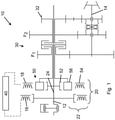
- FIG 1 An embodiment of the transmission system 10 is shown.
- Drive power is transmitted to an input shaft 12 from a drive, usually an internal combustion engine.
- the prime mover can also be a hydraulic motor.
- the Input shaft 12 is rotatably connected to a rotor of the input-side electric machine, as well as the inner rotor 52 of the magnetic-electric planetary gear stage 50.
- the input shaft is also used to supply drive power for a power take-off shaft or PTO and is designed as a continuous shaft.
- the input-side electric machine 16 is electrically connected to the output-side electric machine 18 and to a transmission system controller 40.
- the output-side electric machine 18 is in operative connection with the modulating ring 56 of the magnetic-electric planetary gear stage 50, which in turn interacts with the inner rotor 52.
- the input-side and output-side electric machine together with the magnetic-electric planetary gear represents the variable transmission branch 24, and together with the input shaft the power-split transmission section 20.
- the mechanical transmission branch 24 is formed from the continuous input shaft 12.
- the modulating ring 56 is connected by means of a hollow shaft which surrounds the input shaft 12 .
- the hollow shaft is designed to be connected to the manual transmission 30 and by means of a power-shift clutch to a first gear pair F1 or to a further gear pair F2.
- the gear pairs F1 and F2 form the manual transmission 30 of the transmission system 10.
- the gear pairs F1 and F2 transmit the drive power to the output shaft 14, which in turn is used for transmission to the output.
- the second pair of gears F2 is not connected in a rotationally fixed manner to the output shaft 14, but is connected in a rotationally fixed manner to the latter via a coupling element by shifting.
- the first pair of gears F1 is non-rotatably connected to the output shaft 14, so that when the coupling element is freewheeling and the power shift clutch in the manual transmission is in a corresponding position, the drive torque is transmitted via the first pair of gears F1.
- Another pair of gears R for a reverse gear can be connected to the second pair of gears F2.
- the direction of rotation is reversed by means of an additional intermediate shaft between the input shaft 12 and the output shaft 14 .
- the gear wheel pair R On the output shaft, the gear wheel pair R is not connected in a rotationally fixed manner to the output shaft 14 and is shifted by means of the coupling element.
- the first gear pair F1, the second gear pair F2 or the reverse gear R are connected to the output.
- the drive power is divided in the power-split transmission section 20 means Control of the input-side electric machine 16 and a corresponding proportion converted into electrical power. The remaining mechanical part is passed through the input shaft 12 or remains in it.
- the electric power is controlled by the transmission system controller 40 and the output electric machine 18 is controlled and supplied with electric power. Controlling the current and voltage influences the torque and speed that is generated, so that the action of the modulating ring 56 and the inner rotor 52 results in an outgoing speed and an outgoing torque at the modulating ring 56 .
- the portion of remaining power in the input shaft is sent to the PTO, while the remaining portion is sent to the gearbox.
- one of the power shift clutches for F1 or F2 is closed, while the other power shift clutch in each case is opened.
- the coupling element on the output shaft 14 is switched over.
- the transmission system would change the moment of inertia due to the change in the power path and the resulting speed and torque, so that this change could be felt by the operator.
- the vehicle experiences a change in speed.
- the invention provides that the electrical drive power is adjusted at the same time as the shifting processes in the manual transmission 30, such that the transmission system controller 40 changes the excitation frequency of the windings in the outer stator 54 of the magnetic-electric planetary gear stage 54.
- the change itself causes no torque or speed change, so the change in inertia of the transmission system is kept very small. With this reduction, the vehicle does not undergo any perceptible change in speed.
- the input torque is applied simultaneously to the first electric machine 16 and to the inner rotor 52 via the input shaft 12 .
- the first electrical machine 16 converts this into electrical power, with the actuation taking place via the transmission system controller 40 .
- the electrical power is delivered via the second electric machine 18 with an outer stator 54 . By changing the excitation frequency, different speeds can be set in the magnetic-electric planetary gear stage.
- the power applied to the inner rotor 52, as the power applied to the outer stator 54 also causes the power to be applied to the modulating ring 56.
- the power is delivered to the transmission 30 via the modulating ring 56 and is conducted via the gear pairs F1, F2 or R by switching the respective clutches.
- the transmission system is capable of compensating for the impulse that occurs at the time of shifting due to a simultaneous change in the speed in the magnetic-electric planetary gear stage 50 and maintaining harmonious, jerk-free operation during shifting operations.
- the transmission system 10 can enable purely electric starting, since there is no mechanical connection between the drive and the output.
- a purely electrical starting can be implemented. This is done in the serial electric launch module 70. This is particularly beneficial with a heavy trailer load, which typically requires a large reduction gear to launch at low vehicle speeds.
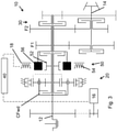
- figure 2 describes a known power-split transmission system from the prior art, which has a variable branch with two outputs 1 and 2.
- the drive power is routed via the input shaft 112 to a first gear wheel G1 and routed to a first electric machine 116 and to a reverse gear 132 by means of the other gear wheels G2 and G zw or G3.
- variable power component is transmitted electrically to a second electric machine 118 and reunited with the mechanical power by means of a magnetic electric planetary gear stage 150 .
- the transmission system according to the prior art has two outputs OUT1 and OUT2, which, depending on the application, can be connected to the output by means of a power shift clutch.
- the drive power is then passed through a manual transmission 130, different translations being set by means of two clutches.
- the solution using two outputs after the power-split transmission allows the outputs to be switched at the same time as the power-shift clutches in the manual transmission 130 are switched. This, together with the change in speed and torque in the manual transmission 130, changes the speed and torque at the output of the power-split transmission section 120. This leads to an equalization of impulse at the switching time.
- the structure of the transmission system 100 is significantly more complex. Two outputs of the power-split transmission section must be reserved, together with two power shift clutches and two additional planetary stages.
- the control of the transmission system 130 is designed in such a way that it is only possible to switch between two different speed ratios. Overall, this leads to greater manufacturing complexity, a higher number of components and increased weight.
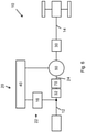
- FIG 3 shows another embodiment of the transmission system according to the invention.
- the first electric machine 16 is driven via a shaft of a gear wheel which is supplied with the input torque at a constant transmission ratio.
- the drive power is introduced into the planet carrier of an epicyclic gear. This has an outer ring that can be blocked and has a power-shift clutch with which the planet carrier can be coupled to the sun.
- the output of the planetary gear is also via the sun, so that the drive power continues to be parallel via the input shaft 12 and the sun shaft.
- variable power component is introduced by means of the second electric machine 18 and a further sun gear of the magnetic-electric planetary gear stage 50, with the modulatable ring 56 being able to be coupled to the inner rotor in the function as a sun gear by means of a further load-shifting clutch.
- the variable power component is regulated between the first and second electric machines 16 and 18 .
- a subsequent gearbox 30 with another parallel shaft to the output follows.
- the gearbox has two gear wheel pairs F1 and F2 which can be coupled to the sun shaft by means of power shift clutches.
- the input shaft 12 is used to supply the PTO or PTO.
- another lower gear is provided as a slow gear or creep.
- the reverse gear in the transmission system 10 is provided by closing or opening the powershift clutch C Fwd , as a result of which the direction of rotation is reversed at the sun gear or at the sun shaft of the planetary gear.
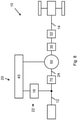
- Figures 4 to 12 show a schematic structure of further embodiments of the transmission system 10 according to the invention.
- the individual components correspond to those of the training figures 1 and 3 .
- figure 4 shows a transmission system 10 according to the invention figure 1 , whereby the version does not have a separate reverse gear.
- the driving torque is divided between the mechanical transmission branch 24 and the variable transmission branch 22, which consists of the first and second electric machines 16 and 18.
- the second electric machine 18 is part of the magnetic-electric planetary gear stage 50.
- the manual transmission 30 is formed following in the power path. Starting from this, the drive power is directed to one or more axles of the vehicle and finally to the output.
- figure 5 shows an embodiment in which the transmission system 10 additionally has a reverse gear 32, which is provided in the power path between the manual transmission 30 and the vehicle axles.
- figure 6 shows an embodiment in which the reverse gear 32 is formed in the area between the first electric machine 16 and the magnetic-electric planetary gear stage 50 in the power path.
- a module for serial electrical starting 70 is provided in the power path, which enables the vehicle to be started without direct mechanical coupling of the drive to the output.
- figure 7 describes an embodiment in which the reverse gear 32 is formed in the power path between the magnetic-electric planetary gear stage 50 and the manual transmission 30 .
- figure 8 shows an embodiment in which the module for serial electric starting 70 is provided in the power path between the first electric machine 16 and the magnetic-electric planetary gear stage 50 . Furthermore, the reverse gear 32 is formed between the transmission 30 and the vehicle axles.
- figure 9 describes an embodiment with the module for serial electric start-up 70 according to FIG figure 8 , with no reverse gear. This is carried out via the magnetic-electric epicyclic gear stage 50, so that a reversal of the direction of rotation is present at the output of the magnetic-electric epicyclic gear stage 50.
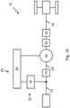
- figure 10 shows a further embodiment, the module for serial electric starting 70 being formed in the power path between the first electric machine 16 and the magnetic-electric planetary gear stage 50 .
- the reverse gear 32 is provided in the power path between the magnetic-electric planetary gear stage 50 and the manual transmission 30 .
- figure 11 shows an embodiment in which the reverse gear 32 within the Manual transmission 30 is formed.
- figure 12 shows an embodiment with the reverse gear 32 in the power path between the first electric machine 16 and the magnetic-electric planetary gear stage 50.
Abstract
Die Erfindung betrifft ein Getriebesystem (10) geeignet für Betrieb mit einer Antriebsmaschine, aufweisend eine Eingangswelle (12) für die Antriebsleitung, wenigstens eine Ausgangswelle (14) für die Abgabe an einen Antrieb, einen leistungsverzweigten Getriebeabschnitt (20), ein Schaltgetriebe (30), eine Getriebesystemsteuerung (40), wobei der leistungsverzweigte Getriebeabschnitt (20) wenigstens einen variablen Getriebezweig (22) und einen mechanischen Getriebezweig (24) aufweist, und der variable Getriebezweig (22) eingangs- und ausgangsseitig jeweils wenigstens eine erste und zweite Elektromaschine (16, 18) für den Generator und Motorbetrieb aufweist, die elektrisch miteinander verbunden sind, wobei die Antriebsleistung durch den mechanischen und variablen Getriebezweig (22, 24) aufgeteilt und geleitet wird, und mit einer eingangsgekoppelten magnetisch elektrischen Umlaufgetriebestufe (50), die den variablen Getriebezweig (22) und mechanischen Getriebezweig (24) zusammenführt, mit einem inneren Rotor (52), einem äußeren Stator (54) und einem modulierenden Ring (56), und die magnetisch elektrische Umlaufgetriebestufe (50) derart von der zweiten Elektromaschine (18) ansteuerbar ist, dass die Ausgangswelle (14) des Getriebesystems (10) entgegen der Drehrichtung an einer Eingangswelle (12) rotiert, wodurch ein Vorwärts- und Rückwärtsbetrieb des Getriebesystems (10) durchführbar ist.The invention relates to a transmission system (10) suitable for operation with a prime mover, having an input shaft (12) for the drive line, at least one output shaft (14) for the output to a drive, a power-split transmission section (20), a manual transmission (30) , a transmission system controller (40), wherein the power-split transmission section (20) has at least one variable transmission branch (22) and one mechanical transmission branch (24), and the variable transmission branch (22) has at least one first and second electric machine (16 , 18) for generator and motor operation, which are electrically connected to one another, with the drive power being divided and routed through the mechanical and variable transmission branch (22, 24), and having an input-coupled magnetic-electric planetary gear stage (50), which controls the variable transmission branch (22) and mechanical transmission branch (24), with an inner rotor (52), an outer stator (54) and a modulating ring (56), and the magnetic-electric planetary gear stage (50) can be controlled in this way by the second electric machine (18). is that the output shaft (14) of the transmission system (10) rotates counter to the direction of rotation on an input shaft (12), whereby forward and reverse operation of the transmission system (10) can be carried out.
Description
Die vorliegende Erfindung betrifft ein Getriebesystem für eine landwirtschaftliche Maschine.The present invention relates to a transmission system for an agricultural machine.
Ein Getriebesystem besteht üblicherweise aus einer Eingangswelle, einem schaltbaren Getriebe und einer Ausgangswelle. Getriebesysteme verändern die eingeleitete Antriebsleistung in Drehmoment und Drehzahl und leiten diese an den Abtrieb weiter.A transmission system usually consists of an input shaft, a shiftable transmission and an output shaft. Transmission systems change the input drive power in terms of torque and speed and forward this to the output.
Ein Getriebesystem kann Schaltgetriebe oder Stufenlosgetriebe als Komponenten verwenden. Schaltgetriebe werden durch lastschaltbare Kupplungen realisiert, die unterschiedliche, im Eingriff stehende Zahnradstufen miteinander verbinden. Dieser Schaltzeitpunkt, auch Lastschaltpunkt genannt, führt zu einer Geschwindigkeitsänderung der im Eingriff stehenden Getriebesystemkomponenten, zu Geräuschentwicklung, Verschleiß und einem unterbrochene Leistungsfluss.A transmission system can use manual transmissions or continuously variable transmissions as components. Manual transmissions are implemented using power-shiftable clutches that connect different gear stages that are in mesh with one another. This shift point, also known as the load shift point, leads to a change in the speed of the engaged transmission system components, to noise development, wear and tear and an interrupted power flow.
Das Getriebesystem kann alternativ als Stufenlosgetriebe umgesetzt werden. Dies ist mittels hydraulischer Variatoren realisiert, um höhere Antriebsleistung sicher umwandeln zu können. Hierbei wird eingangsseitig des Stufenlosgetriebes mittels Hydrostaten ein Teil der Antriebsleistung in hydraulische Leistung umgewandelt. Mittels der Variatoren kann der Anteil der hydraulischen Leistung variiert werden. Ausgangsseitig wird die hydraulische Energie wieder in mechanische Energie umgewandelt. Meist haben Stufenlosgetriebe eine Ausgangswelle, um den Aufbau zu vereinfachen. Dies erfordert zum Schaltzeitpunkt des Getriebesystems gleichzeitig mit dem Gangwechsel im nachgeschalteten Getriebe eine Drehzahländerung an der Variatorausgangswelle. Dieser Vorgang beansprucht Zeit, die den Schaltvorgang verlangsamt und zu einer Trägheit des Getriebesystems führt.Alternatively, the transmission system can be implemented as a continuously variable transmission. This is implemented using hydraulic variators in order to be able to safely convert higher drive power. Here, part of the drive power is converted into hydraulic power on the input side of the continuously variable transmission by means of hydrostats. The share of the hydraulic power can be varied by means of the variators. On the output side, the hydraulic energy is converted back into mechanical energy. Most continuously variable transmissions have an output shaft to simplify the structure. At the time of shifting of the transmission system, this requires a speed change at the variator output shaft at the same time as the gear change in the downstream transmission. This process takes time, which slows down the shifting process and causes sluggishness in the transmission system.
Als Möglichkeit kann das Getriebesystem mit einem Stufenlosgetriebe mit zwei Variatorausgangswellen ausgestattet sein. Hierbei kann auf einen gleichzeitigen Drehzahlwechsel mit dem Schaltvorgang verzichtet werden. Diese Art von Aufbau für zu einer gesteigerten Komplexität, bedingt durch den zweiten Variatorausgang zusammen mit höhere Bauteileanzahl. Insgesamt weisen solche Getriebesysteme einen erhöhten Wartungsaufwand auf, zusammen mit einem erhöhten Verschleiß und stärkerer Geräuschentwicklung.As an option, the transmission system can be equipped with a continuously variable transmission with two variator output shafts. Here, a simultaneous speed change with the shifting process can be dispensed with. This type of design leads to increased complexity due to the second variator output along with higher component count. Overall, such transmission systems have an increased maintenance effort, together with increased wear and noise.
Die vorliegende Erfindung stellt ein Getriebesystem zur Verfügung, dass die angesprochenen Probleme überwindet.The present invention provides a transmission system that overcomes the problems addressed.
Das erfindungsgemäße Getriebesystem ist geeignet für Betrieb mit einer Antriebsmaschine, und weist eine Eingangswelle für die Antriebsleitung auf, wenigstens eine Ausgangswelle für die Abgabe an einen Antrieb, einen leistungsverzweigten Getriebeabschnitt, ein Schaltgetriebe, eine Getriebesystemsteuerung, wobei der leistungsverzweigte Getriebeabschnitt wenigstens einen variablen Getriebezweig und einen mechanischen Getriebezweig aufweist, und der variable Zweig eingangs- und ausgangsseitig jeweils wenigstens eine Elektromaschine für den Generator und Motorbetrieb aufweist, die elektrisch miteinander verbunden sind, wobei die Antriebsleistung durch den mechanischen und variablen Zweig aufgeteilt und geleitet wird, und mit einer eingangsgekoppelten magnetisch elektrischen Umlaufgetriebestufe, die den variablen Zweig und mechanischen Zweig zusammenführt, mit einem inneren Rotor, einem äußeren Stator und einem modulierenden Ring, und die magnetisch elektrische Umlaufgetriebestufe derart von der zweiten Elektromaschine ansteuerbar ist, dass die Ausgangswelle des Getriebesystems entgegen der Drehrichtung an einer Eingangswelle rotiert, wodurch ein Vorwärts- und Rückwärtsbetrieb des Getriebesystems durchführbar ist.The transmission system according to the invention is suitable for operation with a prime mover and has an input shaft for the drive line, at least one output shaft for delivery to a drive, a power-split transmission section, a manual transmission, a transmission system control, the power-split transmission section having at least one variable transmission branch and one mechanical transmission branch, and the variable branch having at least one electric machine for generator and motor operation on the input and output side, which are electrically connected to each other, with the drive power being divided and directed through the mechanical and variable branches, and with an input-coupled magnetic-electric planetary gear stage, which brings the variable branch and mechanical branch together, with an inner rotor, an outer stator and a modulating ring, and the magnetic-electric planetary gear stage can be actuated by the second electric machine in such a way that the output shaft of the gear system rotates on an input shaft in the opposite direction to the direction of rotation, resulting in a forward and backward movement forward operation of the transmission system is feasible.
Bei dem erfindungsgemäßen Getriebesystem und der Verwendung von Elektromaschinen im variablen Zweig zusammen mit einer magnetisch elektrischen Umlaufgetriebestufe, wird im Schaltpunkt des Getriebes gleichzeitig die Erregerfrequenz in den Statorwicklungen der magnetisch elektrischen Umlaufgetriebestufe umgeschaltet. Durch diese Schaltung findet eine Veränderung der Drehzahl einer Zwischenwelle statt. Hierbei wird jedoch nur ein geringes Drehmoment benötigt, so dass ein schnellerer Schaltvorgang des Getriebesystems ermöglicht wird im Vergleich zum Stand der Technik. Die Schaltvorgänge reduzieren damit den Koordinierungsaufwand der Bedienperson und verkürzen die Dauer des Schaltvorgangs. Hierbei wird das Fahrzeug geringeren Geschwindigkeitsschwankungen ausgesetzt, so dass ein erhöhter Fahrkomfort sichergestellt wird.In the transmission system according to the invention and the use of electric machines in the variable branch together with a magnetic-electric planetary gear stage, the excitation frequency in the stator windings of the magnetic-electric planetary gear stage is switched over at the switching point of the transmission at the same time. This circuit changes the speed of an intermediate shaft. In this case, however, only a small amount of torque is required, so that a faster shifting process of the transmission system is made possible in comparison to the prior art. The switching processes thus reduce the coordination effort on the part of the operator and shorten the duration of the switching process. Here, the vehicle is exposed to lower speed fluctuations, so that increased driving comfort is ensured.
In einer weiteren Ausführung wird die magnetisch elektrische Umlaufgetriebestufe derart von der zweiten Elektromaschine angesteuert, dass eine Ausgangswelle der magnetisch elektrischen Umlaufgetriebestufe in Gegenrichtung zur Eingangswelle des Getriebesystems rotiert.In a further embodiment, the magnetic-electric planetary gear stage is controlled by the second electric machine in such a way that an output shaft of the magnetic-electric planetary gear stage rotates in the opposite direction to the input shaft of the transmission system.
Die Ansteuerung der magnetisch elektrischen Umlaufgetriebestufe ermöglicht eine Überlagerung der Drehzahl und Richtung der Eingangswelle mit einem Ausgang der magnetisch elektrischen Umlaufgetriebestufe, so dass eine resultierende Ausgangsdrehzahl und Drehrichtung der Ausgangswelle entgegengesetzt zur Eingangswelle eingestellt wird. Ein zusätzlicher Rückwärtsgang kann entfallen und der gesamte Aufbau des Getriebesystems wird vereinfacht, wodurch die benötigte Teileanzahl und entsprechende Herstellungs- und Einbauvorgänge reduziert werden.The control of the magnetic-electric planetary gear stage enables the speed and direction of the input shaft to be superimposed with an output of the magnetic-electric planetary gear stage, so that a resulting output speed and direction of rotation of the output shaft is set opposite to the input shaft. An additional reverse gear can be omitted and the The entire structure of the transmission system is simplified, thereby reducing the number of parts required and the associated manufacturing and assembly processes.
Bei einer weiteren Ausbildung ist ein zusätzliches Modul zur Drehrichtungsumkehr zwischen der ersten Elektromaschine und der magnetisch elektrischen Umlaufgetriebestufe im Leistungsfluss vorgesehen.In a further embodiment, an additional module for reversing the direction of rotation is provided between the first electric machine and the magnetic-electric planetary gear stage in the power flow.
Das Modul zur Drehrichtungsumkehr kann separat ausgeführt werden vom Schaltgetriebe. Damit wird die Komplexität reduziert. Das Modul kann für ein geringeres Drehmoment ausgelegt werden, wodurch Produktionsaufwand und Teilegewicht reduziert wird.The module for reversing the direction of rotation can be implemented separately from the gearbox. This reduces the complexity. The module can be designed for a lower torque, which reduces production costs and part weight.
Bei einer Weiterbildung ist ein Gang des Schaltgetriebes ein zusätzlicher Rückwärtsgang.In one development, one gear of the manual transmission is an additional reverse gear.
Mit der Integration des Rückwärtsgangs in das Schaltgetriebe wird die Kompatibilität zu gewöhnlichen Schaltgetrieben hergestellt. Der notwendige Bauraum für den leistungsverzweigten Getriebeabschnitt wird reduziert.With the integration of the reverse gear in the manual transmission, compatibility with conventional manual transmissions is established. The space required for the power-split transmission section is reduced.
In einer Ausführung ist ein zusätzliches Modul zur Drehrichtungsumkehr zwischen der magnetisch elektrischen Umlaufgetriebestufe und dem Schaltgetriebe im Leistungsfluss vorgesehen.In one embodiment, an additional module for reversing the direction of rotation is provided between the magnetic-electric planetary gear stage and the manual transmission in the power flow.
Die separate Anordnung erleichtert die Zugänglichkeit des Moduls zu Instandhaltungszwecken.The separate arrangement facilitates the accessibility of the module for maintenance purposes.
Bei einer Weiterbildung ist ein zusätzliches Modul zum seriell elektrischen Anfahren im Leistungsfluss vorgesehen.In one development, an additional module for serial electric start-up in the power flow is provided.
Das Modul ermöglicht das Anfahren des Fahrzeugs durch den elektrischen Leistungszweig, der dem Leistungsfluss über die zwei Elektromaschinen entspricht bei gleichzeitiger Abschaltung des mechanischen Leistungszweigs. Durch das rein elektrische Anfahren kann ein hohes Drehmoment an den Abtrieb geleitet werden. Dies ist besonders bei Anfahren mit einem hohen Zugmoment des Fahrzeuges von Vorteil, da hier bei geringer Fahrgeschwindigkeit hohe Zugkräfte aufgebracht werden müssen. Mittels des Moduls ist dies sichergestellt.The module enables the vehicle to be started using the electrical power branch, which corresponds to the power flow via the two electric machines while the mechanical power branch is switched off at the same time. Due to the purely electric start-up, a high torque can be transmitted to the output. This is particularly advantageous when starting off with a high tractive torque of the vehicle, since high tractive forces have to be applied here at low driving speeds. This is ensured by the module.
In einer Ausführung ist das Modul zum seriell elektrischen Anfahren zwischen der Eingangswelle des Getriebesystems und der magnetisch elektrischen Umlaufgetriebestufe im Leistungsfluss vorgesehen.In one embodiment, the module for serial electric starting is provided between the input shaft of the transmission system and the magnetic-electric planetary gear stage in the power flow.
Aufgrund des Moduls findet eine mechanische Entkopplung des primären Antriebs vom Abtrieb des Fahrzeugs statt. Die Antriebsleistung wird in elektrische Leistung umgewandelt und an den Abtrieb geleitet. Durch das Vorsehen im Leistungsfluss vor der magnetisch elektrischen Umlaufgetriebestufe kann das Modul innerhalb des leistungsverzweigten Getriebeabschnitts angeordnet werden. Die Elektromaschinen können hier für die Umwandlung und Abgabe verwendet werden.Due to the module, the primary drive is mechanically decoupled from the vehicle's output. The drive power is converted into electrical power and routed to the output. By providing the power flow in front of the magnetic-electric planetary gear stage, the module can be arranged within the power-split transmission section. The electric machines can be used here for conversion and delivery.
Bei einer Ausbildung ist das Modul zum seriell elektrischen Anfahren im Leistungsfluss zwischen der ersten Elektromaschine und der magnetisch elektrischen Umlaufgetriebestufe vorgesehen.In one embodiment, the module for serial electric start-up is provided in the power flow between the first electric machine and the magnetic-electric planetary gear stage.
Durch das Vorsehen im Leistungsfluss vor der magnetisch elektrischen Umlaufgetriebestufe kann das Modul innerhalb des leistungsverzweigten Getriebeabschnitts angeordnet werden. Die Elektromaschinen können hier für die Umwandlung und Abgabe verwendet werden.By providing the power flow in front of the magnetic-electric planetary gear stage, the module can be arranged within the power-split transmission section. The electric machines can be used here for conversion and delivery.
In einer Weiterbildung ist das Modul zum seriell elektrischen Anfahren im Leistungsfluss zwischen dem Modul zur Drehrichtungsumkehr und der magnetisch elektrischen Umlaufgetriebestufe vorgesehen.In a further development, the module for serial electric start-up is provided in the power flow between the module for reversing the direction of rotation and the magnetic-electric planetary gear stage.
Die Erfindung wird weiterhin anhand der folgenden Figuren beschrieben. Dabei zeigt:
- Fig. 1
- einen Aufbau des erfindungsgemäßen Getriebesystems;
- Fig. 2
- einen Aufbau aus dem Stand der Technik;
- Fig. 3
- einen weiteren Aufbau des erfindungsgemäßen Getriebesystems;
- Fig. 4
- einen weiteren schematischen Aufbau des Getriebesystems;
- Fig. 5
- einen weiteren schematischen Aufbau des Getriebesystems;
- Fig. 6
- einen weiteren schematischen Aufbau des Getriebesystems;
- Fig. 7
- einen weiteren schematischen Aufbau des Getriebesystems;
- Fig. 8
- einen weiteren schematischen Aufbau des Getriebesystems;
- Fig. 9
- einen weiteren schematischen Aufbau des Getriebesystems;
- Fig. 10
- einen weiteren schematischen Aufbau des Getriebesystems;
- Fig. 11
- einen weiteren schematischen Aufbau des Getriebesystems;
- Fig. 12
- einen weiteren schematischen Aufbau des Getriebesystems.
- 1
- a structure of the transmission system according to the invention;
- 2
- a prior art structure;
- 3
- another structure of the transmission system according to the invention;
- 4
- another schematic structure of the transmission system;
- figure 5
- another schematic structure of the transmission system;
- 6
- another schematic structure of the transmission system;
- 7
- another schematic structure of the transmission system;
- 8
- another schematic structure of the transmission system;
- 9
- another schematic structure of the transmission system;
- 10
- another schematic structure of the transmission system;
- 11
- another schematic structure of the transmission system;
- 12
- another schematic structure of the transmission system.
In
Die eingangsseitige Elektromaschine 16 ist elektrisch mit der ausgangsseitigen Elektromaschine 18 verbunden und mit einer Getriebesystemsteuerung 40. Die ausgangsseitigen Elektromaschine 18 ist in Wirkverbindung mit dem modulierenden Ring 56 der magnetisch elektrischen Umlaufgetriebestufe 50, welcher wiederrum mit dem inneren Rotor 52 zusammenwirkt. Die eingangsseitige und ausgangsseitige Elektromaschine stellt zusammen mit der magnetisch elektrischen Umlaufgetriebestufe den variablen Getriebezweig 24 dar, und zusammen mit der Eingangswelle den leistungsverzweigten Getriebeabschnitt 20. Der mechanische Getriebezweig 24 wird aus der durchgehenden Eingangswelle 12 gebildet.The input-side
Im Leistungsfluss daran anschließend ist der modulierende Ring 56 mittels einer Hohlwelle verbunden, welche die Eingangswelle 12 umgibt. Die Hohlwelle ist in Verbindung mit dem Schaltgetriebe 30 und mittels einer Lastschaltkupplung mit einem ersten Zahnradpaar F1 oder einem weiteren Zahnradpaar F2 verbindbar ausgeführt. Die Zahnradpaare F1 und F2 bilden das Schaltgetriebe 30 des Getriebesystems 10. Die Zahnradpaare F1 und F2 übertragen die Antriebsleistung auf die Ausgangswelle 14, welche wiederrum zur Weiterleitung an den Abtrieb dient. Das zweite Zahnradpaar F2 ist nicht drehfest mit der Ausgangswelle 14 verbunden, sondern wird über ein Kopplungselement durch Schalten drehfest mit dieser verbunden. Das erste Zahnradpaar F1 ist drehfest mit der Ausgangswelle 14 verbunden, so dass bei einem Freilauf des Kopplungselements und bei entsprechender Stellung der Lastschaltkupplung im Schaltgetriebe das Antriebsmoment über das erste Zahnradpaar F1 geleitet wird.Following this in the power flow, the modulating
Mit dem zweiten Zahnradpaar F2 kann ein weiteres Zahnradpaar R für einen Rückwärtsgang verbunden sein. Mittels einer zusätzlichen Zwischenwelle zwischen der Eingangswelle 12 und der Ausgangswelle 14 erfolgt die Drehrichtungsumkehr. Auf der Ausgangswelle ist das Zahnradpaar R nicht drehfest mit der Ausgangswelle 14 verbunden und wird mittels des Kopplungselements geschaltet. Es ist somit je nach Stellung des Kopplungselements und der Lastschaltkupplung das erste Zahnradpaar F1, das zweite Zahnradpaar F2 oder der Rückwärtsgang R an den Abtrieb gelegt.Another pair of gears R for a reverse gear can be connected to the second pair of gears F2. The direction of rotation is reversed by means of an additional intermediate shaft between the
Die Antriebsleistung wird im leistungsverzweigten Getriebeabschnitt 20 aufgeteilt mittles Ansteuerung der eingangsseitigen Elektromaschine 16 und ein entsprechender Anteil in elektrische Leistung umgewandelt. Der verbleibende mechanische Anteil wird durch die Eingangswelle 12 geleitet bzw. verbleibt in dieser. Die elektrische Leistung wird mittels der Getriebesystemsteuerung 40 kontrolliert und die ausgangsseitige Elektromaschine 18 angesteuert und mit elektrischer Leistung versorgt. Durch die Kontrolle von Strom und Spannung wird das erzeugte Drehmoment und die Drehzahl beeinflusst, so dass sich mit der Einwirkung des modulierenden Rings 56 und des inneren Rotors 52 eine abgehende Drehzahl und ein abgehendes Drehmoment am modulierenden Ring 56 einstellt.The drive power is divided in the power-
Der Anteil an verbleibender Leistung in der Eingangswelle wird an die Zapfwelle geleitet, während der weitere Anteil an das Schaltgetriebe geleitet wird.The portion of remaining power in the input shaft is sent to the PTO, while the remaining portion is sent to the gearbox.
Zu einem Schaltzeitpunkt, bei entsprechendem Ansteuern durch die Getriebesystemsteuerung erfolgt ein Schließen einer der Lastschaltkupplungen für F1 oder F2, während die jeweils andere Lastschaltkupplung geöffnet wird. Gleichzeitig erfolgt ein Umschalten des Kopplungselements auf der Ausgangswelle 14. Durch den Wechsel des Leistungspfades und der daraus resultierenden Drehzahl sowie dem Drehmoment, würde ohne die Erfindung das Getriebesystem eine Änderung des Trägheitsmoments, so dass diese Änderung von der Bedienperson spürbar ist. Gleichzeitig erfährt das Fahrzeug eine Geschwindigkeitsänderung.At a shift point in time, with appropriate activation by the transmission system controller, one of the power shift clutches for F1 or F2 is closed, while the other power shift clutch in each case is opened. At the same time, the coupling element on the
Um dies zu verhindern ist erfindungsgemäß vorgesehen, dass gleichzeitig mit den Schaltvorgängen im Schaltgetriebe 30 eine Anpassung der elektrischen Antriebsleistung erfolgt, derart, dass durch die Getriebesystemsteuerung 40 eine Änderung der Erregerfrequenz der Wicklungen im äußeren Stator 54 der magnetisch elektrischen Umlaufgetriebestufe 54 erfolgt. Die Änderung selbst verursacht kein Drehmoment oder Drehzahländerung, so dass die Veränderung des Trägheitsmoments des Getriebesystems sehr klein gehalten wird. Durch diese Verringerung durchläuft das Fahrzeug keine wahrnehmbare Geschwindigkeitsänderung.In order to prevent this, the invention provides that the electrical drive power is adjusted at the same time as the shifting processes in the
Das Eingangsmoment liegt über die Eingangswelle 12 gleichzeitig an der ersten Elektromaschine 16 und an dem inneren Rotor 52 an. Die erste Elektromaschine 16 wandelt dieses in elektrische Leistung um, wobei die Ansteuerung über die Getriebesystemsteuerung 40 erfolgt. Die elektrische Leistung wird über die zweite Elektromaschine 18 mit einem äußeren Stator 54 abgegeben. Durch eine Änderung der Erregerfrequenz können unterschiedliche Drehzahlen in der magnetisch elektrischen Umlaufgetriebestufe eingestellt werden. Die anliegende Leistung am inneren Rotor 52, als auch die anliegende Leistung am äußeren Stator 54 bedingt die sich anstellende Leistung am modulierenden Ring 56. Die Leistung wird über den modulierenden Ring 56 an das Schaltgetriebe 30 abgegeben und durch Schalten der jeweiligen Kupplungen über die Zahnradpaare F1, F2 oder R geleitet.The input torque is applied simultaneously to the first
Insgesamt ist das Getriebesystem in der Lage, am Schaltzeitpunkt den sich einstellenden Impuls ein gleichzeitiges Ändern der Drehzahl in der magnetisch elektrischen Umlaufgetriebestufe 50 auszugleichen und einen harmonischen, ruckfreien Betrieb während Schaltvorgängen zu erhalten.Overall, the transmission system is capable of compensating for the impulse that occurs at the time of shifting due to a simultaneous change in the speed in the magnetic-electric
Das Getriebesystem 10 kann gleichzeitig das rein elektrische Anfahren ermöglichen, da keine mechanische Verbindung zwischen dem Antrieb und dem Abtrieb besteht. Durch das Vorhalten von Batteriespeicher und der Einspeisung von zusätzlicher elektrischer Energie in die zweite Elektromaschine 18 kann so ein reines elektrisches Anfahren umgesetzt werden. Dies erfolgt im Modul zum seriell elektrischen Anfahren 70. Dies ist besonders von Vorteil bei einer hohen Anhängelast, die bei geringen Fahrgeschwindigkeiten normalerweise eine starke Untersetzung erfordert, um anzufahren.At the same time, the
Die Antriebsleistung wird über die Eingangswelle 112 zu einem ersten Zahnrad G1 geleitet und mittels der weiteren Zahnräder G2 und Gzw bzw. G3 jeweils an eine erste Elektromaschine 116 und an einen Rückwärtsgang 132 geleitet.The drive power is routed via the
Der variable Leistungsanteil wird zu einer zweiten Elektromaschine 118 elektrisch übertragen und mittels einer magnetische elektrischen Umlaufgetriebestufe 150 wieder mit der mechanischen Leistung vereint. Im Unterschied zur vorliegenden Erfindung weist das Getriebesystem nach dem Stand der Technik zwei Ausgänge OUT1 und OUT2 auf, die je nach Anwendung mittels einer Lastschaltkupplung mit dem Abtrieb verbunden werden können. Daran anschließend wird die Antriebsleistung durch ein Schaltgetriebe 130 geleitet, wobei mittels zwei Kupplungen unterschiedliche Übersetzungen festgelegt werden.The variable power component is transmitted electrically to a second
Die Lösung mittels zwei Ausgängen nach dem Leistungsverzweigten Getriebe ermöglicht das Umschalten der Ausgänge zeitgleich zum Umschalten der Lastschaltkupplungen im Schaltgetriebe 130. Hierdurch wird zusammen mit der Änderung der Drehzahl und des Drehmoments im Schaltgetriebe 130 die Drehzahl und das Drehmoment am Ausgang des leistungsverzweigen Getriebeabschnitts 120 geändert. Dies führt zu einem Ausgleich des Impulses im Schaltzeitpunkt. Im Unterschied zur vorliegenden Erfindung ist der Aufbau des Getriebesystems 100 wesentlich komplexer. Es müssen zwei Ausgänge des leistungsverzweigten Getriebeabschnitts vorgehalten werden, zusammen mit zwei Lastschaltkupplungen und zwei zusätzlichen Planetenstufen. Parallel ist die Steuerung des Getriebesystems 130 so ausgelegt, dass nur zwischen zwei unterschiedlichen Drehzahlverhältnissen umgeschaltet werden kann. Insgesamt führt dies zu einer höheren Fertigungskomplexität, einer höheren Bauteilanzahl und einem gesteigerten Gewicht.The solution using two outputs after the power-split transmission allows the outputs to be switched at the same time as the power-shift clutches in the
Der Rückwärtsgang im Getriebesystem 10 wird über das Schließen oder Öffnen der Lastschaltkupplung CFwd bereitgestellt, wodurch eine Drehrichtungsumkehr am Sonnenrad bzw. an der Sonnenwelle des Planetengetriebes erfolgt.The reverse gear in the
Claims (9)
Priority Applications (1)
| Application Number | Priority Date | Filing Date | Title |
|---|---|---|---|
| EP23185453.0A EP4246014A3 (en) | 2020-07-29 | 2021-07-12 | Transmission system |
Applications Claiming Priority (1)
| Application Number | Priority Date | Filing Date | Title |
|---|---|---|---|
| DE102020119984.8A DE102020119984A1 (en) | 2020-07-29 | 2020-07-29 | transmission system |
Related Child Applications (1)
| Application Number | Title | Priority Date | Filing Date |
|---|---|---|---|
| EP23185453.0A Division EP4246014A3 (en) | 2020-07-29 | 2021-07-12 | Transmission system |
Publications (1)
| Publication Number | Publication Date |
|---|---|
| EP3945665A1 true EP3945665A1 (en) | 2022-02-02 |
Family
ID=76890813
Family Applications (2)
| Application Number | Title | Priority Date | Filing Date |
|---|---|---|---|
| EP21184936.9A Pending EP3945665A1 (en) | 2020-07-29 | 2021-07-12 | Transmission system |
| EP23185453.0A Pending EP4246014A3 (en) | 2020-07-29 | 2021-07-12 | Transmission system |
Family Applications After (1)
| Application Number | Title | Priority Date | Filing Date |
|---|---|---|---|
| EP23185453.0A Pending EP4246014A3 (en) | 2020-07-29 | 2021-07-12 | Transmission system |
Country Status (3)
| Country | Link |
|---|---|
| US (1) | US11691497B2 (en) |
| EP (2) | EP3945665A1 (en) |
| DE (1) | DE102020119984A1 (en) |
Citations (5)
| Publication number | Priority date | Publication date | Assignee | Title |
|---|---|---|---|---|
| US20090247341A1 (en) * | 2006-10-25 | 2009-10-01 | Honda Motor Co., Ltd. | Power plant |
| EP2179879A1 (en) * | 2007-08-27 | 2010-04-28 | Kabushiki Kaisha Toyota Chuo Kenkyusho | Power transmission device |
| DE102010022527A1 (en) * | 2009-06-03 | 2010-12-16 | Kabushiki Kaisha Toyota Chuo Kenkyusho | Power transmission device has speed regulation transmission device with input shaft, on which drive power of drive motor is transferred, where output shaft transfers drive power on load |
| WO2013121266A1 (en) * | 2012-02-14 | 2013-08-22 | Toyota Jidosha Kabushiki Kaisha | Drive unit for vehicle |
| CN108340766A (en) * | 2018-01-03 | 2018-07-31 | 北京理工大学 | Hybrid power system, vehicle and its control method |
Family Cites Families (4)
| Publication number | Priority date | Publication date | Assignee | Title |
|---|---|---|---|---|
| DE102017208985A1 (en) | 2017-05-29 | 2018-11-29 | Deere & Company | Magnetic epicyclic gearbox with variable torque |
| DE102017219758A1 (en) | 2017-11-07 | 2019-05-09 | Deere & Company | differential assembly |
| DE102018200953A1 (en) * | 2018-01-22 | 2019-07-25 | Deere & Company | Vehicle with an arrangement for the dynamic adaptation of the flow |
| DE102018204405A1 (en) | 2018-03-22 | 2019-09-26 | Deere & Company | PTO |
-
2020
- 2020-07-29 DE DE102020119984.8A patent/DE102020119984A1/en active Pending
-
2021
- 2021-07-06 US US17/305,350 patent/US11691497B2/en active Active
- 2021-07-12 EP EP21184936.9A patent/EP3945665A1/en active Pending
- 2021-07-12 EP EP23185453.0A patent/EP4246014A3/en active Pending
Patent Citations (5)
| Publication number | Priority date | Publication date | Assignee | Title |
|---|---|---|---|---|
| US20090247341A1 (en) * | 2006-10-25 | 2009-10-01 | Honda Motor Co., Ltd. | Power plant |
| EP2179879A1 (en) * | 2007-08-27 | 2010-04-28 | Kabushiki Kaisha Toyota Chuo Kenkyusho | Power transmission device |
| DE102010022527A1 (en) * | 2009-06-03 | 2010-12-16 | Kabushiki Kaisha Toyota Chuo Kenkyusho | Power transmission device has speed regulation transmission device with input shaft, on which drive power of drive motor is transferred, where output shaft transfers drive power on load |
| WO2013121266A1 (en) * | 2012-02-14 | 2013-08-22 | Toyota Jidosha Kabushiki Kaisha | Drive unit for vehicle |
| CN108340766A (en) * | 2018-01-03 | 2018-07-31 | 北京理工大学 | Hybrid power system, vehicle and its control method |
Also Published As
| Publication number | Publication date |
|---|---|
| US20220032763A1 (en) | 2022-02-03 |
| US11691497B2 (en) | 2023-07-04 |
| DE102020119984A1 (en) | 2022-02-03 |
| EP4246014A2 (en) | 2023-09-20 |
| EP4246014A3 (en) | 2023-11-08 |
Similar Documents
| Publication | Publication Date | Title |
|---|---|---|
| EP3707411B1 (en) | Power split continuously variable transmission with at least four travel ranges | |
| DE19521486B4 (en) | An adjusting coupling transmission | |
| DE102016204727A1 (en) | Continuously power split transmission with at least one driving range | |
| WO2012055527A1 (en) | Transmission unit and electric extension unit | |
| DE102018213893A1 (en) | Motor vehicle transmission, in particular for an agricultural or municipal utility vehicle, and motor vehicle drive train | |
| DE102019200966B4 (en) | Power-split motor vehicle transmission | |
| DE102017206413A1 (en) | Power-split continuously variable transmission system | |
| DE102018213891B4 (en) | Motor vehicle transmission, in particular for an agricultural or municipal utility vehicle, and motor vehicle drive train | |
| DE102018213876A1 (en) | Motor vehicle transmission, in particular for an agricultural or municipal utility vehicle, and motor vehicle drive train | |
| DE102018213890A1 (en) | Motor vehicle transmission, in particular for an agricultural or municipal utility vehicle, and motor vehicle drive train | |
| DE102018213888A1 (en) | Motor vehicle transmission, in particular for an agricultural or municipal utility vehicle, and motor vehicle drive train | |
| EP3945665A1 (en) | Transmission system | |
| DE102018213884B4 (en) | Motor vehicle transmission, in particular for an agricultural or municipal utility vehicle, and motor vehicle drive train | |
| DE102018213881A1 (en) | Motor vehicle transmission, in particular for an agricultural or municipal utility vehicle, and motor vehicle drive train | |
| DE102018213879A1 (en) | Motor vehicle transmission, in particular for an agricultural or municipal utility vehicle, and motor vehicle drive train | |
| DE102018213875A1 (en) | Motor vehicle transmission, in particular for an agricultural or municipal utility vehicle, and motor vehicle drive train | |
| DE102018213885B4 (en) | Motor vehicle transmission, in particular for an agricultural or municipal utility vehicle, and motor vehicle drive train | |
| DE102018213892B4 (en) | Motor vehicle transmission, in particular for an agricultural or municipal utility vehicle, and motor vehicle drive train | |
| DE102018213887B4 (en) | Motor vehicle transmission, in particular for an agricultural or municipal utility vehicle, and motor vehicle drive train | |
| DE102019200970B4 (en) | Motor vehicle transmission, in particular for an agricultural or municipal commercial vehicle, and motor vehicle drive train | |
| DE102017219126B4 (en) | Power-split continuously variable transmission device | |
| DE102017219105B4 (en) | Power-split continuously variable transmission device | |
| DE102017219129B4 (en) | Power-split continuously variable transmission device | |
| DE102017219100B4 (en) | Power-split continuously variable transmission device | |
| DE102022200713A1 (en) | Drive train for a working machine |
Legal Events
| Date | Code | Title | Description |
|---|---|---|---|
| PUAI | Public reference made under article 153(3) epc to a published international application that has entered the european phase |
Free format text: ORIGINAL CODE: 0009012 |
|
| STAA | Information on the status of an ep patent application or granted ep patent |
Free format text: STATUS: THE APPLICATION HAS BEEN PUBLISHED |
|
| AK | Designated contracting states |
Kind code of ref document: A1 Designated state(s): AL AT BE BG CH CY CZ DE DK EE ES FI FR GB GR HR HU IE IS IT LI LT LU LV MC MK MT NL NO PL PT RO RS SE SI SK SM TR |
|
| STAA | Information on the status of an ep patent application or granted ep patent |
Free format text: STATUS: REQUEST FOR EXAMINATION WAS MADE |
|
| 17P | Request for examination filed |
Effective date: 20220802 |
|
| RBV | Designated contracting states (corrected) |
Designated state(s): AL AT BE BG CH CY CZ DE DK EE ES FI FR GB GR HR HU IE IS IT LI LT LU LV MC MK MT NL NO PL PT RO RS SE SI SK SM TR |
|
| STAA | Information on the status of an ep patent application or granted ep patent |
Free format text: STATUS: EXAMINATION IS IN PROGRESS |
|
| 17Q | First examination report despatched |
Effective date: 20230508 |