EP3945658A1 - Polyphase motor, manufacturing method and kitchen appliance - Google Patents
Polyphase motor, manufacturing method and kitchen appliance Download PDFInfo
- Publication number
- EP3945658A1 EP3945658A1 EP20188325.3A EP20188325A EP3945658A1 EP 3945658 A1 EP3945658 A1 EP 3945658A1 EP 20188325 A EP20188325 A EP 20188325A EP 3945658 A1 EP3945658 A1 EP 3945658A1
- Authority
- EP
- European Patent Office
- Prior art keywords
- stator
- rotor
- electric coils
- electric
- casing
- Prior art date
- Legal status (The legal status is an assumption and is not a legal conclusion. Google has not performed a legal analysis and makes no representation as to the accuracy of the status listed.)
- Granted
Links
Images


Classifications
-
- H—ELECTRICITY
- H02—GENERATION; CONVERSION OR DISTRIBUTION OF ELECTRIC POWER
- H02K—DYNAMO-ELECTRIC MACHINES
- H02K1/00—Details of the magnetic circuit
- H02K1/06—Details of the magnetic circuit characterised by the shape, form or construction
- H02K1/12—Stationary parts of the magnetic circuit
- H02K1/14—Stator cores with salient poles
-
- H—ELECTRICITY
- H02—GENERATION; CONVERSION OR DISTRIBUTION OF ELECTRIC POWER
- H02K—DYNAMO-ELECTRIC MACHINES
- H02K1/00—Details of the magnetic circuit
- H02K1/06—Details of the magnetic circuit characterised by the shape, form or construction
- H02K1/22—Rotating parts of the magnetic circuit
- H02K1/27—Rotor cores with permanent magnets
- H02K1/2706—Inner rotors
- H02K1/272—Inner rotors the magnetisation axis of the magnets being perpendicular to the rotor axis
- H02K1/2726—Inner rotors the magnetisation axis of the magnets being perpendicular to the rotor axis the rotor consisting of a single magnet or two or more axially juxtaposed single magnets
- H02K1/2733—Annular magnets
-
- H—ELECTRICITY
- H02—GENERATION; CONVERSION OR DISTRIBUTION OF ELECTRIC POWER
- H02K—DYNAMO-ELECTRIC MACHINES
- H02K7/00—Arrangements for handling mechanical energy structurally associated with dynamo-electric machines, e.g. structural association with mechanical driving motors or auxiliary dynamo-electric machines
- H02K7/003—Couplings; Details of shafts
-
- H—ELECTRICITY
- H02—GENERATION; CONVERSION OR DISTRIBUTION OF ELECTRIC POWER
- H02K—DYNAMO-ELECTRIC MACHINES
- H02K2213/00—Specific aspects, not otherwise provided for and not covered by codes H02K2201/00 - H02K2211/00
- H02K2213/12—Machines characterised by the modularity of some components
-
- H—ELECTRICITY
- H02—GENERATION; CONVERSION OR DISTRIBUTION OF ELECTRIC POWER
- H02K—DYNAMO-ELECTRIC MACHINES
- H02K7/00—Arrangements for handling mechanical energy structurally associated with dynamo-electric machines, e.g. structural association with mechanical driving motors or auxiliary dynamo-electric machines
- H02K7/10—Structural association with clutches, brakes, gears, pulleys or mechanical starters
- H02K7/116—Structural association with clutches, brakes, gears, pulleys or mechanical starters with gears
Definitions
- the present invention concerns a polyphase motor having a stator comprising electric coils and a magnetised rotor, which rotates around a rotation axis within the stator when the electric coils are energised, a method for manufacturing the polyphase motor and a kitchen appliance.
- a known polyphase motor is shown in the European patent EP 0 949 747 B1 .
- the motor is a three-phase electric commutated motor having a stator excited by electric coils and by a magnetised rotor, which rotates around a rotation axis within the stator when the electric coils are energised.
- the stator provides a casing for receiving three electric coils.
- the electric coils are positioned radial outside to the rotor and are evenly spaced around its circumference.
- Each electric coil has one coil core.
- the coil cores are formed by radial, integral projections of the casing. In a top view, the core coils have the shape of an elongated rectangular body, whereas the radial inner end of the projections form the pole shoes.
- the poles shoes are rounded and positioned within the electric coils.
- pole shoes could be useful which are positioned outside of the electric coils and extending at least over a part of the electric coils.
- an object of the present invention to provide a polyphase motor with enlarged pole shoes which is easy to manufacture, a manufacturing method for such a polyphase motor and a kitchen appliance with a powerful polyphase motor.
- a polyphase motor comprises a stator and a rotor.
- the stator is excited by electric coils.
- the rotor is magnetised and rotates around a rotation axis within the stator when the electric coils are energised.
- the stator forms a casing for receiving the electric coils.
- the electric coils are positioned radial outside the rotor and are evenly spaced around the circumference.
- Each electric coil has one coil core, wherein each coil core has an end section for interlocking with a counter element of the stator. On its opposite end, each coil core provides a pole shoe delimiting an area of a ring gap between the rotor and the respective electric coil.
- the polyphase motor is a three phase electrically commutated motor (3 phase EC motor).
- the motor is preferable produced by stacking several metal sheets of a magnetically material, this allowing magnetic flux but preventing eddy current in the stator casing if the adjacent metal sheets are isolated in an adequate manner.
- the motor has three electric coils as active teeth and three passive teeth. As the coil cores are not an integrated part of the stator casing, they can be inserted into the electric coils first, and then the electric coils with the inserted coil cores can be mounted to the stator casing. This enables the creating of large pole shoes as the electric coils do not have to be pushed from the pole shoes side on the coil cores. As in the preferred embodiment the pole shoes are an integral part of the core coils, the motor is compact.
- the interlocking end section has a dovetail-shaped projection and the stator casing shows a respective recess as counterpart.
- the dovetail recess into the coil core and the dovetail-shaped projection into the stator recess.
- Dovetails connections are reliable, easy to manufacture and easy to assembly and to disassembly.
- the coil cores are produced in the similar way as the stator casing, that means by stacking up several metal sheets of magnetic material.
- electric isolating material sheets are positions between adjacent metal sheets, in order to increase its performance even more.
- the passive stator teeth helping to form a ring gap with a small radial extension surrounding the rotor.
- the electric coils are positioned in reception rooms of the casing and between two adjacent reception rooms the passive teeth of the casing are formed having the same radial distance from the rotation axis of the rotor as the pole shoes.
- the size of the motor can be effectively reduced, if electrical pins of the electrical coils which are necessary to establish an electrical connection between the coil windings and a circuit board such as a printed circuit board, are positioned close to each other, so that the circuit board can be of small size. This can be achieved if the electrical pins are positioned at a radial inner position. Therefore, it is preferred, if the receptions rooms for the electric coils have at their radial inner portions lateral widenings (cut outs) adapted to receive the electrical pins which extends axially from one side to the other side of the electric coils.
- each electric coil can have a bobbin with radially inner portions adapted to form stop faces at least on one stator side when the stator is assembled in a motor casing.
- the stop faces are formed integrally at each bobbin.
- the bobbins are made of plastics.
- the rotor comprises a Halbach sinusoidal oriented magnet ring.
- magnet ring enables a quit running of the rotor and high motor torque.
- the rotor is made of plastics and forming integrally the rotor shaft, a bearing system, a pinion and axially limitations for the magnet ring. Due to this, both the manufacturing of the rotor and the compactness of the rotor is improved.
- a retention system is provided between the magnetic ring and the rotor shaft.
- the retention system is integrated into the rotor such that it is automatically created when rotor shaft is built up and the magnet ring is hold in position.
- a method to manufacture a multiphase motor proposes that the electric coils are releasable fixed to the stator casing by means of an interlocking connection between their active teeth and the stator casing.
- This has the major advantage that large pole shoes can be formed integrally with the active teeth, thus increasing motor torque and decrease vibration of the motor caused by cogging torque.
- the pole shoes can have a circumferential extension similar to or even larger than the extension of the electric coils in circumferential direction as the active teeth can be inserted into the electric coils with their end building the form-fit.
- a kitchen appliance according to the invention comprises a polyphase motor according to an embodiment of the present invention.
- Such kitchen appliance has a powerful, compact quit and smooth running motor, resulting in a noise reduction.
- FIG. 1 a sectional top view on an exemplary embodiment of a polyphase motor 1 according to the present invention is shown.
- the polyphase motor 1 is a three phase electrical commutated motor (3 phase EC motor).
- the motor has a stator 2 and a rotor 4, which rotates around a rotation axis X within the stator 2 when electric coils 6 of the stator 1 are energised.
- the motor 1 is installed in a kitchen appliance and acting as drive system or being at least a part of a drive system.
- the stator 2 has a casing that is made by stacking several metal sheets 8 of a magnetically material ( figures 2 and 3 ). Preferable, the metal sheets 8 are electrical isolated from each other in order to avoid eddy current which would reduce the performance of the motor 1.
- the stator casing defines an internal space which is divided into one central portion 10 for receiving the rotor 4 and in three reception rooms 12 extending radially outwards from the central portion 10 and are evenly spaced around the circumference of the rotor.
- These portions of the stator 2 are also called stator yokes.
- each reception room 12 one electric coil 6 is positioned on a coil core 14.
- the coil cores 14, also called active teeth, are orientated radially inwards. They have a longitudinal cross section and are also made by stacking several metal sheets 16 of a magnetically material ( figure 3 ). Preferable, the metal sheets 16 are also electrical isolated from each other in order to avoid eddy current which, again, would reduce the performance of the motor 1.
- the active teeth 14 are releasable fixed to the stator casing via an interlocking connection 20.
- the interlocking connection 20 is formed as a dovetail connection, wherein the active teeth 14 show dovetail projections 18 and the stator casing respective dovetail recesses 22 as counter-element (see in detail figure 4 ).
- the dovetail-connection 20 extents parallel to the rotation axis X.
- radial inner ends of the active teeth 14 are enlarged in circumferential direction and formed as pole shoes 24 (see also figure 3 ).
- the pole shoes 24 extents from both sides of the active teeth 14 in circumferential direction nearly over the entire extension of each electric coil 6 in circumferential direction and are arc-shaped.
- the active teeth 14 together with the dovetail projections 18 and the integral formed pole shoes 24 have a T-like shape.
- the pole shoes 24 are arc-shaped in such a manner that they are in a close distance to the rotor 4, thus delimiting an area of an annular gap 26 between the rotor 4 and the respective electric coils 6.
- the electric coils 6 have a bobbin 28, preferably a bobbin made of plastics.
- each bobbin 28 has two enlarged radially inward portions acting as stop faces 30 during the assembly.
- the inward portions are only on one side of the stator 1, in particular on its back side.
- each bobbin 28 has on both sides of its recess for entering the active teeth 14 two longitudinal rails 31 extending in assembly direction of the electrical coils 6.
- each electric coil 6 receives one pair of pins 32.
- the pins 32 are carried by the bobbin 28 and are positioned in radial inner lateral widenings 34 of the reception rooms 12.
- the pins 32 extend in axial direction over the entire length of the electric coils 6 parallel to the rotation axis X.
- the pins 32 are electrically connected to the non-shown circuit board ( figure 6 ). Due to the radial inner position of the circuit board, the circuit board itself is of reduced size.
- portions 38 of the stator casing have the same radial distance from the rotation axis X as the pole shoes 24. These casing portions 38 are arc-shaped and are called passive teeth of the stator 1. In combination with the pole shoes 24, these passive teeth 38 build the small annular gap 26 between the rotor 4 and the stator 2.
- FIG 5 and figure 6 a back view of the stator 2 and a front view of the stator 2 is shown ready for being assembled in a motor casing.
- the electric coils 6 with their windings, coils cores 14 and bobbins 28 are positioned in the reception rooms 12 on the active teeth 14 and the pole shoes 24 together with the passive teeth 38 between them delimiting the central portion 10 for the rotor 4.
- Each active tooth 14 is releasable interlocked with the stator casing via an interlocking connection 20, preferably a dovetail connection.
- the stop faces 30 and the electric connection 36 of the electric coil windings with the pins 32 are illustrated.
- the pins 32 with their electric contact elements 39 are provided for receiving the circuit board.
- the routing of electrical conduits of the pins 32 are electrically isolated within the pins 32.
- an inventive rotor 4 of the preferred embodiment of a polyphase motor 1 is shown.
- the rotor 4 comprises of a rotor shaft 40, bearing system 42 (shaft bearing), a magnet ring 44, and a pinion 46 in order to transfer its rotation and torque to a gearbox, for instance.
- the bearing system 42 is formed as a longitudinal through bore extending along the rotation axis X of the rotor shaft 40.
- the bearing system 42 is designed as a slide bearing.
- the magnet ring 44 is preferably designed as a Halbach sinusoidal oriented magnet ring.
- the rotor shaft 40, the bearing system 42 and the pinion 46 are made of a plastics material and formed as one integral part.
- the magnetic ring 44 is positioned on the rotor shaft 40 and laterally coated, in particular overmolded, with plastics, whereby the magnetic ring 44 is fixed axially on the rotor shaft 40.
- at least one retention system 48 is provided securing the magnetic ring 44 in circumferential direction on the rotor shaft 40.
- the retention system 48 is preferably designed as an interlocking connection and formed integrally with the rotor 4. More preferably, three retention systems 48 are provided which are evenly spaced around the circumference of the magnetic ring 44.
- stator casing and the active teeth 14 are built up separately.
- the electric coils 6 are winded on their bobbins 28 and the pins 32 are fixed in the bobbins 28 or will be fixed to the bobbins 28 after the winding is finished.
- the pins 32 will be electronically connected with the coil windings.
- the active teeth 14 are introduced into the electric coils 6 and the electric coils 6 are mounted to the stator casing by form-fitting the dovetail projections 18 of the active teeth14 with the respective dovetail recesses 22 of the stator casing.
- the equipped stator 2 is positioned via its stop faces 30 in a motor casing and the rotor 1 is inserted in the central portion 10 of the stator 2, thereby being rotatable positioned around the rotation axis X via its bearing system 42 on a respective counterpart of the motor casing.
- a multiphase motor 1 having a stator 2 comprising electric coils 6, and a magnetised rotor 4, which rotates around a rotation axis X within the stator 2 when the electric coils 6 are energised, wherein the stator provides a casing for receiving the electric coils 6, wherein the electric coils 6 are positioned radial outside to the rotor 4 and are evenly spaced around the circumference, and wherein each electric coil 6 has a coil core 14, wherein each coil core 14 has an end section 18 for interlocking with a counter element 20 of the stator 2 and at its opposite end a pole shoe 24 delimiting an area of an annular gap 26 between the rotor 4 and the respective electric coil 6, am manufacturing method of the motor and a kitchen appliance.
Landscapes
- Engineering & Computer Science (AREA)
- Power Engineering (AREA)
- Iron Core Of Rotating Electric Machines (AREA)
Abstract
Description
- The present invention concerns a polyphase motor having a stator comprising electric coils and a magnetised rotor, which rotates around a rotation axis within the stator when the electric coils are energised, a method for manufacturing the polyphase motor and a kitchen appliance.
- A known polyphase motor is shown in the European patent
EP 0 949 747 B1 . The motor is a three-phase electric commutated motor having a stator excited by electric coils and by a magnetised rotor, which rotates around a rotation axis within the stator when the electric coils are energised. The stator provides a casing for receiving three electric coils. The electric coils are positioned radial outside to the rotor and are evenly spaced around its circumference. Each electric coil has one coil core. The coil cores are formed by radial, integral projections of the casing. In a top view, the core coils have the shape of an elongated rectangular body, whereas the radial inner end of the projections form the pole shoes. The poles shoes are rounded and positioned within the electric coils. - In order to enhance the performance of the motor, pole shoes could be useful which are positioned outside of the electric coils and extending at least over a part of the electric coils.
- It is, therefore, an object of the present invention to provide a polyphase motor with enlarged pole shoes which is easy to manufacture, a manufacturing method for such a polyphase motor and a kitchen appliance with a powerful polyphase motor.
- The problem is solved by a polyphase motor according to
claim 1, by a manufacturing method according toclaim 10 and by a kitchen appliance according to claim 11. Advantageous embodiments are disclosed in the dependent claims, the description and the figures. - A polyphase motor according to the invention comprises a stator and a rotor. The stator is excited by electric coils. The rotor is magnetised and rotates around a rotation axis within the stator when the electric coils are energised. The stator forms a casing for receiving the electric coils. The electric coils are positioned radial outside the rotor and are evenly spaced around the circumference. Each electric coil has one coil core, wherein each coil core has an end section for interlocking with a counter element of the stator. On its opposite end, each coil core provides a pole shoe delimiting an area of a ring gap between the rotor and the respective electric coil.
- In a preferred embodiment the polyphase motor is a three phase electrically commutated motor (3 phase EC motor). The motor is preferable produced by stacking several metal sheets of a magnetically material, this allowing magnetic flux but preventing eddy current in the stator casing if the adjacent metal sheets are isolated in an adequate manner. In this preferred embodiment, the motor has three electric coils as active teeth and three passive teeth. As the coil cores are not an integrated part of the stator casing, they can be inserted into the electric coils first, and then the electric coils with the inserted coil cores can be mounted to the stator casing. This enables the creating of large pole shoes as the electric coils do not have to be pushed from the pole shoes side on the coil cores. As in the preferred embodiment the pole shoes are an integral part of the core coils, the motor is compact.
- Preferably, the interlocking end section has a dovetail-shaped projection and the stator casing shows a respective recess as counterpart. However, it is also possible to integrate the dovetail recess into the coil core and the dovetail-shaped projection into the stator recess. Dovetails connections are reliable, easy to manufacture and easy to assembly and to disassembly.
- In the preferred embodiment, the coil cores are produced in the similar way as the stator casing, that means by stacking up several metal sheets of magnetic material. Preferably, electric isolating material sheets are positions between adjacent metal sheets, in order to increase its performance even more.
- In order to increase motor torque and decrease vibration of the motor caused by cogging torque, the passive stator teeth helping to form a ring gap with a small radial extension surrounding the rotor. In order to create such small (thin) ring gap, the electric coils are positioned in reception rooms of the casing and between two adjacent reception rooms the passive teeth of the casing are formed having the same radial distance from the rotation axis of the rotor as the pole shoes.
- The size of the motor can be effectively reduced, if electrical pins of the electrical coils which are necessary to establish an electrical connection between the coil windings and a circuit board such as a printed circuit board, are positioned close to each other, so that the circuit board can be of small size. This can be achieved if the electrical pins are positioned at a radial inner position. Therefore, it is preferred, if the receptions rooms for the electric coils have at their radial inner portions lateral widenings (cut outs) adapted to receive the electrical pins which extends axially from one side to the other side of the electric coils.
- In order to facilitate the assembly in a motor casing, each electric coil can have a bobbin with radially inner portions adapted to form stop faces at least on one stator side when the stator is assembled in a motor casing. Preferably, the stop faces are formed integrally at each bobbin. Preferably, the bobbins are made of plastics.
- In the preferred embodiment, the rotor comprises a Halbach sinusoidal oriented magnet ring. Such as magnet ring enables a quit running of the rotor and high motor torque.
- Preferably, the rotor is made of plastics and forming integrally the rotor shaft, a bearing system, a pinion and axially limitations for the magnet ring. Due to this, both the manufacturing of the rotor and the compactness of the rotor is improved.
- In order to avoid any loss of the magnetic ring from the rotor shaft and in order to transfer reliable rotation movements and torque moments between the magnetic ring and rotor shaft, a retention system is provided between the magnetic ring and the rotor shaft. The retention system is integrated into the rotor such that it is automatically created when rotor shaft is built up and the magnet ring is hold in position.
- A method to manufacture a multiphase motor according to one of the preceding claims, proposes that the electric coils are releasable fixed to the stator casing by means of an interlocking connection between their active teeth and the stator casing. This has the major advantage that large pole shoes can be formed integrally with the active teeth, thus increasing motor torque and decrease vibration of the motor caused by cogging torque. The pole shoes can have a circumferential extension similar to or even larger than the extension of the electric coils in circumferential direction as the active teeth can be inserted into the electric coils with their end building the form-fit.
- A kitchen appliance according to the invention comprises a polyphase motor according to an embodiment of the present invention. Such kitchen appliance has a powerful, compact quit and smooth running motor, resulting in a noise reduction.
- In the following, a preferred embodiment of the present invention is explained with respect to accompanying drawings. As is to be understood, the various elements and components are depicted as examples only, may be facultative and/or combined in a manner different than that depicted. Reference signs for related elements are used comprehensively and not defined again for each figure. Shown is schematically in
- Fig. 1:
- a sectional top view of an exemplary embodiment of a polyphase motor according to the present invention;
- Fig. 2
- single stator sheets without an active teeth sheet,
- Fig. 3:
- single stator sheets with a active teeth sheet,
- Fig. 4:
- an enlarged view of a preferred interlocking connection of the coil core with the stator casing
- Fig. 5:
- a back view of the exemplary embodiment,
- Fig. 6:
- a front view of the exemplary embodiment,
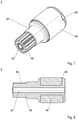
- Fig. 7:
- a perspective view of a rotor of the exemplary embodiment, and
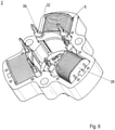
- Fig. 8:
- a longitudinal section of the rotor.
- For illustrative purposes, only some elements are referenced with a reference number, even if there is more than one of the respective element shown in the figures.
- In
Figure 1 , a sectional top view on an exemplary embodiment of apolyphase motor 1 according to the present invention is shown. Thepolyphase motor 1 is a three phase electrical commutated motor (3 phase EC motor). The motor has astator 2 and arotor 4, which rotates around a rotation axis X within thestator 2 whenelectric coils 6 of thestator 1 are energised. Exemplary, themotor 1 is installed in a kitchen appliance and acting as drive system or being at least a part of a drive system. - The
stator 2 has a casing that is made by stackingseveral metal sheets 8 of a magnetically material (figures 2 and 3 ). Preferable, themetal sheets 8 are electrical isolated from each other in order to avoid eddy current which would reduce the performance of themotor 1. - Back to
figure 1 , the stator casing defines an internal space which is divided into onecentral portion 10 for receiving therotor 4 and in threereception rooms 12 extending radially outwards from thecentral portion 10 and are evenly spaced around the circumference of the rotor. These portions of thestator 2 are also called stator yokes. - In each
reception room 12 oneelectric coil 6 is positioned on acoil core 14. Thecoil cores 14, also called active teeth, are orientated radially inwards. They have a longitudinal cross section and are also made by stackingseveral metal sheets 16 of a magnetically material (figure 3 ). Preferable, themetal sheets 16 are also electrical isolated from each other in order to avoid eddy current which, again, would reduce the performance of themotor 1. - With their radial outer end, the
active teeth 14 are releasable fixed to the stator casing via aninterlocking connection 20. In the shown embodiment, the interlockingconnection 20 is formed as a dovetail connection, wherein theactive teeth 14 showdovetail projections 18 and the stator casing respective dovetail recesses 22 as counter-element (see in detailfigure 4 ). The dovetail-connection 20 extents parallel to the rotation axis X. - As also illustrated in
figures 1 , radial inner ends of theactive teeth 14 are enlarged in circumferential direction and formed as pole shoes 24 (see alsofigure 3 ). The pole shoes 24 extents from both sides of theactive teeth 14 in circumferential direction nearly over the entire extension of eachelectric coil 6 in circumferential direction and are arc-shaped. Thus, theactive teeth 14 together with thedovetail projections 18 and the integral formedpole shoes 24 have a T-like shape. The pole shoes 24 are arc-shaped in such a manner that they are in a close distance to therotor 4, thus delimiting an area of anannular gap 26 between therotor 4 and the respectiveelectric coils 6. - The
electric coils 6 have abobbin 28, preferably a bobbin made of plastics. In order to facilitate an assembly and a positioning of thestator 2 in a motor casing, eachbobbin 28 has two enlarged radially inward portions acting as stop faces 30 during the assembly. Preferably, the inward portions are only on one side of thestator 1, in particular on its back side. In order to facilitate the positioning of theelectric coils 6 within thereception rooms 12, eachbobbin 28 has on both sides of its recess for entering theactive teeth 14 twolongitudinal rails 31 extending in assembly direction of theelectrical coils 6. - In order to connect the
electric coils 6 electrically, for instance with a circuit board such as printed circuit board (PCB), three pairs ofpins 32 are provided. Eachelectric coil 6 receives one pair ofpins 32. Thepins 32 are carried by thebobbin 28 and are positioned in radial innerlateral widenings 34 of thereception rooms 12. Thepins 32 extend in axial direction over the entire length of theelectric coils 6 parallel to the rotation axis X. On one side, in this embodiment the back side of thestator 1, eachpin 32 receives onefree end 36 of the coil windings (figure 5 ). On the opposite side, in this embodiment the front side of thestator 1, thepins 32 are electrically connected to the non-shown circuit board (figure 6 ). Due to the radial inner position of the circuit board, the circuit board itself is of reduced size. - Back to
figure 1 , between twoadjacent reception rooms 12,portions 38 of the stator casing have the same radial distance from the rotation axis X as the pole shoes 24. Thesecasing portions 38 are arc-shaped and are called passive teeth of thestator 1. In combination with the pole shoes 24, thesepassive teeth 38 build the smallannular gap 26 between therotor 4 and thestator 2. - In
figure 5 andfigure 6 a back view of thestator 2 and a front view of thestator 2 is shown ready for being assembled in a motor casing. Theelectric coils 6 with their windings, coilscores 14 andbobbins 28 are positioned in thereception rooms 12 on theactive teeth 14 and the pole shoes 24 together with thepassive teeth 38 between them delimiting thecentral portion 10 for therotor 4. Eachactive tooth 14 is releasable interlocked with the stator casing via aninterlocking connection 20, preferably a dovetail connection. As shown infigure 5 , at the back of thestator 2, the stop faces 30 and theelectric connection 36 of the electric coil windings with thepins 32 are illustrated. As shown infigure 6 , at the front of thestator 2, thepins 32 with theirelectric contact elements 39 are provided for receiving the circuit board. In order to avoid any negative impact on the performance of themotor 1 such as short circuit current, the routing of electrical conduits of thepins 32 are electrically isolated within thepins 32. - In
figures 7 and 8 , aninventive rotor 4 of the preferred embodiment of apolyphase motor 1 is shown. Therotor 4 comprises of arotor shaft 40, bearing system 42 (shaft bearing), amagnet ring 44, and apinion 46 in order to transfer its rotation and torque to a gearbox, for instance. The bearingsystem 42 is formed as a longitudinal through bore extending along the rotation axis X of therotor shaft 40. Thus, the bearingsystem 42 is designed as a slide bearing. Themagnet ring 44 is preferably designed as a Halbach sinusoidal oriented magnet ring. - The
rotor shaft 40, the bearingsystem 42 and thepinion 46 are made of a plastics material and formed as one integral part. Themagnetic ring 44 is positioned on therotor shaft 40 and laterally coated, in particular overmolded, with plastics, whereby themagnetic ring 44 is fixed axially on therotor shaft 40. In order to avoid any rotational slip between themagnetic ring 44 and therotor shaft 40, at least oneretention system 48 is provided securing themagnetic ring 44 in circumferential direction on therotor shaft 40. Theretention system 48 is preferably designed as an interlocking connection and formed integrally with therotor 4. More preferably, threeretention systems 48 are provided which are evenly spaced around the circumference of themagnetic ring 44. - In the following, a preferred method according to the invention is described. According to an inventive method of the invention, the stator casing and the
active teeth 14 are built up separately. - The
electric coils 6 are winded on theirbobbins 28 and thepins 32 are fixed in thebobbins 28 or will be fixed to thebobbins 28 after the winding is finished. Thepins 32 will be electronically connected with the coil windings. - After that, the
active teeth 14 are introduced into theelectric coils 6 and theelectric coils 6 are mounted to the stator casing by form-fitting thedovetail projections 18 of the active teeth14 with the respective dovetail recesses 22 of the stator casing. - Thereby, the
electric coils 6 positioned on theactive teeth 14 are inserted axially into thereception rooms 12 until the final position in the stator casing is reached. - Then, the equipped
stator 2 is positioned via its stop faces 30 in a motor casing and therotor 1 is inserted in thecentral portion 10 of thestator 2, thereby being rotatable positioned around the rotation axis X via itsbearing system 42 on a respective counterpart of the motor casing. - Disclosed is a
multiphase motor 1 having astator 2 comprisingelectric coils 6, and amagnetised rotor 4, which rotates around a rotation axis X within thestator 2 when theelectric coils 6 are energised, wherein the stator provides a casing for receiving theelectric coils 6, wherein theelectric coils 6 are positioned radial outside to therotor 4 and are evenly spaced around the circumference, and wherein eachelectric coil 6 has acoil core 14, wherein eachcoil core 14 has anend section 18 for interlocking with acounter element 20 of thestator 2 and at its opposite end apole shoe 24 delimiting an area of anannular gap 26 between therotor 4 and the respectiveelectric coil 6, am manufacturing method of the motor and a kitchen appliance. -
- 1
- motor
- 2
- stator
- 4
- rotor
- 6
- electric coil
- 8
- metal sheet (stator casing)
- 10
- central portion
- 12
- reception room / passive teeth
- 14
- coil core / active teeth
- 16
- metal sheet (coil core)
- 18
- dovetail projection
- 20
- interlocking connection
- 22
- dovetail recess
- 24
- pole shoe
- 26
- annular gap
- 28
- bobbin
- 30
- stop face
- 31
- rail
- 32
- pin
- 34
- widening / cut-out
- 36
- free end of coil winding
- 38
- portion of stator casing / passive teeth
- 39
- electric contact element
- 40
- rotor shaft
- 42
- shaft bearing
- 44
- magnet ring
- 46
- pinion
- 48
- retention system
- X
- rotation axis of the rotor within the stator
Claims (11)
- A polyphase motor, comprising:
a stator (2) comprising electric coils (6), and a magnetised rotor (4), which rotates around a rotation axis (X) within the stator (2) when the electric coils (6) are energised, wherein the stator provides a casing for receiving the electric coils (6), wherein the electric coils (6) are positioned radial outside to the rotor (4) and are evenly spaced around the circumference, and wherein each electric coil (6) has a coil core (14), wherein each coil core (14) has an end section (18) for interlocking with a counter element (20) of the stator (2) and at its opposite end a pole shoe (24) delimiting an area of an annular gap (26) between the rotor (4) and the respective electric coil (6). - A polyphase motor according to claim 1, wherein the interlocking end section (18) has a dovetail-shape.
- A polyphase motor according to claim 1 or 2, wherein the coil cores (14) are produced by stacking up several metal sheets (16) of magnetic material.
- A polyphase motor according to claim 1, 2 or 3, wherein the electric coils (6) are positioned in reception rooms (12) of the casing and between two adjacent reception rooms (12) the casing has basically the same radial distance from the rotation axis (X) as the pole shoes (24).
- A polyphase motor according to claim 3, wherein the receptions rooms (12) have lateral widenings adapted to receive electrical pins (32) of the electric coils (6) which extends axially from one side to the other side of the electric coils (6).
- A polyphase motor according to claim 5, wherein each electric coil (6) has a bobbin (28) with a radially inner portion adapted to form stop faces (30) when the stator (2) is assembled in a motor casing.
- A polyphase motor according to any of the preceding claims, wherein the rotor (4) comprises a Halbach sinusoidal oriented magnet ring (44).
- A polyphase motor according to any of the preceding claims, wherein the rotor (4) is made of plastic material integrally forming a rotor shaft (40), a shaft bearing system (42), a pinion (44) and axially limitations for the magnet ring (44).
- A polyphase motor according to claim 9, wherein an integrated retention (48) system is provided in order to transfer rotation movements and torque moments between the magnetic ring (44) and the rotor shaft (40).
- Method to manufacture a multiphase motor according to one of the preceding claims, wherein the electric coils (6) are releasable fixed to the stator casing by means of an interlocking connection (20) between the coil cores (14) and the stator casing.
- Kitchen appliance comprising a polyphase motor according to one of the claims 1 to 9
Priority Applications (2)
| Application Number | Priority Date | Filing Date | Title |
|---|---|---|---|
| PL20188325.3T PL3945658T3 (en) | 2020-07-29 | 2020-07-29 | Polyphase motor, manufacturing method and kitchen appliance |
| EP20188325.3A EP3945658B1 (en) | 2020-07-29 | 2020-07-29 | Polyphase motor, manufacturing method and kitchen appliance |
Applications Claiming Priority (1)
| Application Number | Priority Date | Filing Date | Title |
|---|---|---|---|
| EP20188325.3A EP3945658B1 (en) | 2020-07-29 | 2020-07-29 | Polyphase motor, manufacturing method and kitchen appliance |
Publications (2)
| Publication Number | Publication Date |
|---|---|
| EP3945658A1 true EP3945658A1 (en) | 2022-02-02 |
| EP3945658B1 EP3945658B1 (en) | 2026-02-25 |
Family
ID=71846253
Family Applications (1)
| Application Number | Title | Priority Date | Filing Date |
|---|---|---|---|
| EP20188325.3A Active EP3945658B1 (en) | 2020-07-29 | 2020-07-29 | Polyphase motor, manufacturing method and kitchen appliance |
Country Status (2)
| Country | Link |
|---|---|
| EP (1) | EP3945658B1 (en) |
| PL (1) | PL3945658T3 (en) |
Cited By (1)
| Publication number | Priority date | Publication date | Assignee | Title |
|---|---|---|---|---|
| WO2024208603A1 (en) * | 2023-04-04 | 2024-10-10 | HELLA GmbH & Co. KGaA | Actuator with motor |
Citations (9)
| Publication number | Priority date | Publication date | Assignee | Title |
|---|---|---|---|---|
| EP0949747B1 (en) | 1996-10-21 | 2003-02-05 | Mmt S.A. | Polyphase motor, in particular for driving the hand of a display |
| JP2007259625A (en) * | 2006-03-24 | 2007-10-04 | Yazaki Corp | Structure to prevent foreign matter from entering the housing |
| EP2006976A1 (en) * | 2007-06-18 | 2008-12-24 | Askoll Holding S.r.l. | Two-phase synchronous electric motor |
| CN201490869U (en) * | 2009-09-29 | 2010-05-26 | 彭希南 | Micro-step stepping motor |
| WO2014041313A1 (en) * | 2012-09-13 | 2014-03-20 | Valeo Equipements Electriques Moteur | Single-tooth stator for a rotating electric machine and corresponding rotating electric machine |
| DE102013105964A1 (en) * | 2013-06-07 | 2014-12-11 | Minebea Co., Ltd. | Rotor with bearing device |
| EP2874291A1 (en) * | 2013-11-19 | 2015-05-20 | Société Industrielle de Sonceboz S.A. | Electric motor |
| EP3134961A2 (en) * | 2014-04-25 | 2017-03-01 | Mmt Ag | Electric actuator |
| US20190229573A1 (en) * | 2016-10-10 | 2019-07-25 | Jiangsu University | Permanent magnet brushless motor having high winding factor, and design and fault-tolerant control methods thereof |
-
2020
- 2020-07-29 EP EP20188325.3A patent/EP3945658B1/en active Active
- 2020-07-29 PL PL20188325.3T patent/PL3945658T3/en unknown
Patent Citations (9)
| Publication number | Priority date | Publication date | Assignee | Title |
|---|---|---|---|---|
| EP0949747B1 (en) | 1996-10-21 | 2003-02-05 | Mmt S.A. | Polyphase motor, in particular for driving the hand of a display |
| JP2007259625A (en) * | 2006-03-24 | 2007-10-04 | Yazaki Corp | Structure to prevent foreign matter from entering the housing |
| EP2006976A1 (en) * | 2007-06-18 | 2008-12-24 | Askoll Holding S.r.l. | Two-phase synchronous electric motor |
| CN201490869U (en) * | 2009-09-29 | 2010-05-26 | 彭希南 | Micro-step stepping motor |
| WO2014041313A1 (en) * | 2012-09-13 | 2014-03-20 | Valeo Equipements Electriques Moteur | Single-tooth stator for a rotating electric machine and corresponding rotating electric machine |
| DE102013105964A1 (en) * | 2013-06-07 | 2014-12-11 | Minebea Co., Ltd. | Rotor with bearing device |
| EP2874291A1 (en) * | 2013-11-19 | 2015-05-20 | Société Industrielle de Sonceboz S.A. | Electric motor |
| EP3134961A2 (en) * | 2014-04-25 | 2017-03-01 | Mmt Ag | Electric actuator |
| US20190229573A1 (en) * | 2016-10-10 | 2019-07-25 | Jiangsu University | Permanent magnet brushless motor having high winding factor, and design and fault-tolerant control methods thereof |
Cited By (1)
| Publication number | Priority date | Publication date | Assignee | Title |
|---|---|---|---|---|
| WO2024208603A1 (en) * | 2023-04-04 | 2024-10-10 | HELLA GmbH & Co. KGaA | Actuator with motor |
Also Published As
| Publication number | Publication date |
|---|---|
| EP3945658B1 (en) | 2026-02-25 |
| PL3945658T3 (en) | 2026-05-25 |
Similar Documents
| Publication | Publication Date | Title |
|---|---|---|
| US11277045B2 (en) | Radially embedded permanent magnet rotor and methods thereof | |
| US10110076B2 (en) | Single-phase brushless motor | |
| US6683397B2 (en) | Electric machine having at least one magnetic field detector | |
| JP6640621B2 (en) | Motor rotor and brushless motor | |
| US6844653B2 (en) | Stator design for permanent magnet motor with combination slot wedge and tooth locator | |
| EP2973943B1 (en) | Axial flux electric machine and methods of assembling the same | |
| US8884491B2 (en) | Multi-gap electric rotating machine with one-piece stator core | |
| US6313557B1 (en) | Electric motor of the electronic commutation type for applications with a feeder line | |
| CN105723596B (en) | Magnetic inductive motor and its manufacturing method | |
| CN101557129A (en) | Manufacture of electric motor component | |
| AU2017379348B2 (en) | Rotary electric machine | |
| US12095322B2 (en) | Stator | |
| EP3471240A1 (en) | Permanent magnet motor | |
| CN110858733A (en) | Axial flux machine and method of assembling the same | |
| KR20140136597A (en) | Rotor structure of drive motor | |
| JPWO2009093380A1 (en) | Laminated laminated core of rotor, rotor core, rotor for permanent magnet type synchronous rotating electric machine equipped with the same, permanent magnet type synchronous rotating electric machine, and vehicle, elevator and processing machine using the same | |
| US20220263356A1 (en) | Motor | |
| WO2008068503B1 (en) | Axial flux electrical machines | |
| KR20170055003A (en) | Stator and bldc motor having the same | |
| JP5332082B2 (en) | motor | |
| WO2002047238A1 (en) | Electrical machine magnetic cores | |
| US8823240B2 (en) | Stator and rotating electrical machine | |
| EP3945658B1 (en) | Polyphase motor, manufacturing method and kitchen appliance | |
| US20170149318A1 (en) | Single Phase Permanent Magnet Brushless Motor | |
| KR100668946B1 (en) | Brushless DC motor |
Legal Events
| Date | Code | Title | Description |
|---|---|---|---|
| PUAI | Public reference made under article 153(3) epc to a published international application that has entered the european phase |
Free format text: ORIGINAL CODE: 0009012 |
|
| STAA | Information on the status of an ep patent application or granted ep patent |
Free format text: STATUS: THE APPLICATION HAS BEEN PUBLISHED |
|
| AK | Designated contracting states |
Kind code of ref document: A1 Designated state(s): AL AT BE BG CH CY CZ DE DK EE ES FI FR GB GR HR HU IE IS IT LI LT LU LV MC MK MT NL NO PL PT RO RS SE SI SK SM TR |
|
| STAA | Information on the status of an ep patent application or granted ep patent |
Free format text: STATUS: REQUEST FOR EXAMINATION WAS MADE |
|
| 17P | Request for examination filed |
Effective date: 20220802 |
|
| RBV | Designated contracting states (corrected) |
Designated state(s): AL AT BE BG CH CY CZ DE DK EE ES FI FR GB GR HR HU IE IS IT LI LT LU LV MC MK MT NL NO PL PT RO RS SE SI SK SM TR |
|
| STAA | Information on the status of an ep patent application or granted ep patent |
Free format text: STATUS: EXAMINATION IS IN PROGRESS |
|
| 17Q | First examination report despatched |
Effective date: 20231219 |
|
| RIC1 | Information provided on ipc code assigned before grant |
Ipc: H02K 1/14 20060101AFI20250801BHEP Ipc: H02K 1/27 20220101ALI20250801BHEP Ipc: H02K 7/00 20060101ALI20250801BHEP Ipc: H02K 1/2733 20220101ALI20250801BHEP Ipc: H02K 7/116 20060101ALN20250801BHEP |
|
| GRAP | Despatch of communication of intention to grant a patent |
Free format text: ORIGINAL CODE: EPIDOSNIGR1 |
|
| STAA | Information on the status of an ep patent application or granted ep patent |
Free format text: STATUS: GRANT OF PATENT IS INTENDED |
|
| RIC1 | Information provided on ipc code assigned before grant |
Ipc: H02K 1/14 20060101AFI20250908BHEP Ipc: H02K 1/27 20220101ALI20250908BHEP Ipc: H02K 7/00 20060101ALI20250908BHEP Ipc: H02K 1/2733 20220101ALI20250908BHEP Ipc: H02K 7/116 20060101ALN20250908BHEP |
|
| INTG | Intention to grant announced |
Effective date: 20250926 |
|
| GRAS | Grant fee paid |
Free format text: ORIGINAL CODE: EPIDOSNIGR3 |
|
| GRAA | (expected) grant |
Free format text: ORIGINAL CODE: 0009210 |
|
| STAA | Information on the status of an ep patent application or granted ep patent |
Free format text: STATUS: THE PATENT HAS BEEN GRANTED |
|
| AK | Designated contracting states |
Kind code of ref document: B1 Designated state(s): AL AT BE BG CH CY CZ DE DK EE ES FI FR GB GR HR HU IE IS IT LI LT LU LV MC MK MT NL NO PL PT RO RS SE SI SK SM TR |
|
| REG | Reference to a national code |
Ref country code: CH Ref legal event code: F10 Free format text: ST27 STATUS EVENT CODE: U-0-0-F10-F00 (AS PROVIDED BY THE NATIONAL OFFICE) Effective date: 20260225 Ref country code: GB Ref legal event code: FG4D |
|
| REG | Reference to a national code |
Ref country code: DE Ref legal event code: R096 Ref document number: 602020067397 Country of ref document: DE |
|
| REG | Reference to a national code |
Ref country code: IE Ref legal event code: FG4D |
|
| REG | Reference to a national code |
Ref country code: NL Ref legal event code: MP Effective date: 20260225 |
|
| PG25 | Lapsed in a contracting state [announced via postgrant information from national office to epo] |
Ref country code: RS Free format text: LAPSE BECAUSE OF FAILURE TO SUBMIT A TRANSLATION OF THE DESCRIPTION OR TO PAY THE FEE WITHIN THE PRESCRIBED TIME-LIMIT Effective date: 20260525 |
|
| PG25 | Lapsed in a contracting state [announced via postgrant information from national office to epo] |
Ref country code: ES Free format text: LAPSE BECAUSE OF FAILURE TO SUBMIT A TRANSLATION OF THE DESCRIPTION OR TO PAY THE FEE WITHIN THE PRESCRIBED TIME-LIMIT Effective date: 20260225 |
|
| PG25 | Lapsed in a contracting state [announced via postgrant information from national office to epo] |
Ref country code: GR Free format text: LAPSE BECAUSE OF FAILURE TO SUBMIT A TRANSLATION OF THE DESCRIPTION OR TO PAY THE FEE WITHIN THE PRESCRIBED TIME-LIMIT Effective date: 20260526 |
|
| REG | Reference to a national code |
Ref country code: LT Ref legal event code: MG9D |
|
| PG25 | Lapsed in a contracting state [announced via postgrant information from national office to epo] |
Ref country code: LT Free format text: LAPSE BECAUSE OF FAILURE TO SUBMIT A TRANSLATION OF THE DESCRIPTION OR TO PAY THE FEE WITHIN THE PRESCRIBED TIME-LIMIT Effective date: 20260225 |
|
| PG25 | Lapsed in a contracting state [announced via postgrant information from national office to epo] |
Ref country code: NO Free format text: LAPSE BECAUSE OF FAILURE TO SUBMIT A TRANSLATION OF THE DESCRIPTION OR TO PAY THE FEE WITHIN THE PRESCRIBED TIME-LIMIT Effective date: 20260525 |
|
| PG25 | Lapsed in a contracting state [announced via postgrant information from national office to epo] |
Ref country code: FI Free format text: LAPSE BECAUSE OF FAILURE TO SUBMIT A TRANSLATION OF THE DESCRIPTION OR TO PAY THE FEE WITHIN THE PRESCRIBED TIME-LIMIT Effective date: 20260225 Ref country code: SE Free format text: LAPSE BECAUSE OF FAILURE TO SUBMIT A TRANSLATION OF THE DESCRIPTION OR TO PAY THE FEE WITHIN THE PRESCRIBED TIME-LIMIT Effective date: 20260225 Ref country code: AT Free format text: LAPSE BECAUSE OF FAILURE TO SUBMIT A TRANSLATION OF THE DESCRIPTION OR TO PAY THE FEE WITHIN THE PRESCRIBED TIME-LIMIT Effective date: 20260225 |
|
| REG | Reference to a national code |
Ref country code: AT Ref legal event code: MK05 Ref document number: 1892122 Country of ref document: AT Kind code of ref document: T Effective date: 20260225 |
|
| PG25 | Lapsed in a contracting state [announced via postgrant information from national office to epo] |
Ref country code: HR Free format text: LAPSE BECAUSE OF FAILURE TO SUBMIT A TRANSLATION OF THE DESCRIPTION OR TO PAY THE FEE WITHIN THE PRESCRIBED TIME-LIMIT Effective date: 20260225 |
|
| PG25 | Lapsed in a contracting state [announced via postgrant information from national office to epo] |
Ref country code: IS Free format text: LAPSE BECAUSE OF FAILURE TO SUBMIT A TRANSLATION OF THE DESCRIPTION OR TO PAY THE FEE WITHIN THE PRESCRIBED TIME-LIMIT Effective date: 20260625 Ref country code: PT Free format text: LAPSE BECAUSE OF FAILURE TO SUBMIT A TRANSLATION OF THE DESCRIPTION OR TO PAY THE FEE WITHIN THE PRESCRIBED TIME-LIMIT Effective date: 20260625 |
|
| PG25 | Lapsed in a contracting state [announced via postgrant information from national office to epo] |
Ref country code: NL Free format text: LAPSE BECAUSE OF FAILURE TO SUBMIT A TRANSLATION OF THE DESCRIPTION OR TO PAY THE FEE WITHIN THE PRESCRIBED TIME-LIMIT Effective date: 20260225 |
|
| PG25 | Lapsed in a contracting state [announced via postgrant information from national office to epo] |
Ref country code: LV Free format text: LAPSE BECAUSE OF FAILURE TO SUBMIT A TRANSLATION OF THE DESCRIPTION OR TO PAY THE FEE WITHIN THE PRESCRIBED TIME-LIMIT Effective date: 20260225 |
|
| PG25 | Lapsed in a contracting state [announced via postgrant information from national office to epo] |
Ref country code: BG Free format text: LAPSE BECAUSE OF FAILURE TO SUBMIT A TRANSLATION OF THE DESCRIPTION OR TO PAY THE FEE WITHIN THE PRESCRIBED TIME-LIMIT Effective date: 20260225 |