EP3945630A1 - Mimetisation structure for 3g+4g multi-sector antennas - Google Patents
Mimetisation structure for 3g+4g multi-sector antennas Download PDFInfo
- Publication number
- EP3945630A1 EP3945630A1 EP21180544.5A EP21180544A EP3945630A1 EP 3945630 A1 EP3945630 A1 EP 3945630A1 EP 21180544 A EP21180544 A EP 21180544A EP 3945630 A1 EP3945630 A1 EP 3945630A1
- Authority
- EP
- European Patent Office
- Prior art keywords
- panels
- mimetisation
- sector antennas
- antennas
- foldable
- Prior art date
- Legal status (The legal status is an assumption and is not a legal conclusion. Google has not performed a legal analysis and makes no representation as to the accuracy of the status listed.)
- Granted
Links
Images



Classifications
-
- H—ELECTRICITY
- H01—ELECTRIC ELEMENTS
- H01Q—ANTENNAS, i.e. RADIO AERIALS
- H01Q1/00—Details of, or arrangements associated with, antennas
- H01Q1/12—Supports; Mounting means
- H01Q1/22—Supports; Mounting means by structural association with other equipment or articles
- H01Q1/24—Supports; Mounting means by structural association with other equipment or articles with receiving set
- H01Q1/241—Supports; Mounting means by structural association with other equipment or articles with receiving set used in mobile communications, e.g. GSM
- H01Q1/246—Supports; Mounting means by structural association with other equipment or articles with receiving set used in mobile communications, e.g. GSM specially adapted for base stations
-
- H—ELECTRICITY
- H01—ELECTRIC ELEMENTS
- H01Q—ANTENNAS, i.e. RADIO AERIALS
- H01Q1/00—Details of, or arrangements associated with, antennas
- H01Q1/42—Housings not intimately mechanically associated with radiating elements, e.g. radome
-
- H—ELECTRICITY
- H01—ELECTRIC ELEMENTS
- H01Q—ANTENNAS, i.e. RADIO AERIALS
- H01Q1/00—Details of, or arrangements associated with, antennas
- H01Q1/12—Supports; Mounting means
- H01Q1/1207—Supports; Mounting means for fastening a rigid aerial element
- H01Q1/1228—Supports; Mounting means for fastening a rigid aerial element on a boom
Definitions
- the present invention relates to a mimetisation structure for multi-sector antennas, which has been conceived and embodied to enable the installation on the inside thereof of both third generation (3G) and fourth generation (4G) antennas with low IP (Intermodulation Product), minimal disturbance in the patterns, minimal gain drop and minimal disturbance in the SWR (Standing Wave Ratio) of the antennas.
- 3G third generation
- 4G fourth generation
- IP Intermodulation Product
- the object of the invention is therefore to provide a structure that enables both types of antennas (3G+4G) to be concealed, without the problems of intermodulation products, known as IPs, that presents a minimal alteration of the gain and the patterns of the antennas as well as a minimal variation of the SWR thereof.
- casings of this type only enable 3 antennas to be housed on the inside thereof.
- the present invention proposes a structure with a square, parallelepipedic plan that conceals the antennas on the inside thereof without producing noticeable disturbances in the parameters of the antennas.
- the mimetisation structure of the invention starts from a bench as a stabilising element for the antenna itself, and incorporates a low-weight and high-stability mast in addition to reducing the number of parts and simplifying the mounting and installation process.
- the mimetisation itself is achieved by means of four panels, preferably made of fibreglass, reinforced with polyester; this material not being limiting or excluding other materials.
- Two of the panels have a C-shaped plan section while the other two panels are flat.
- One of the flat panels is foldable or has a lateral opening by way of a door to enable access to the inside for installation and maintenance.
- third and fourth generation or 3G+4G antennas are installed, with the corresponding protective radome thereof.
- This radome as described above, has a square plan formed by two C-shaped parts or shells, a flat face and a final flat face that is used as access for installation work of the antennas and possible maintenance with the particularity that said mast-radome assembly is finished off with a top cover to prevent the entry of water. In this way, a multi-sector and self-stable antenna is achieved, which enables third and fourth generation 3G+4G antennas to be simply integrated in one same device.
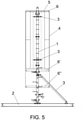
- the mimetisation structure of the invention starts from a mast (1) as a support element for the 3G and 4G antennas, which is linked to a bench (2), by means of screws, as well as by oblique bars (3), without ruling out other resistive elements, such as pillars, facings and the like, main (2) mast (1) with the two supports (3) that will serve for the installation of the corresponding 3G and 4G antennas.
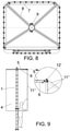
- the mast assembly with the antennas will be covered by a radome (4) with a prismatic configuration and a quadrangular plan, which is finished off with a square upper cover (5), and which is linked to said mast (1) by means of anchors (6) as shown in detail in Figure 8 , materialised in a sort of quadrangular ring (7) with diagonal arms (8) that are linked to a clamp (9) by means of which they are fixed to the aforementioned mast (1), being able to use anchors (6-6'-6") at different heights of the radome.
- the aforementioned radome (4) is obtained from at least four panels, preferably made of fibreglass, reinforced with polyester, such that these panels can be subdivided into several parts that are sewn vertically together, according to the height of said radome.
- two of the panels have a C-shaped plan section (10) while the other two panels are flat panels (11-11'-11"), one of these flat panels (11'-11") being foldable, either by means of hinges (12) with a vertical rotation axis, such as the variant embodiment shown in Figure 3 , or where said flat panel (11") extends from the upper end to the lower end of one of the faces of the prism, being articulated with respect to horizontal axis hinges (12') linked to the upper anchoring structure (5).
- this door that constitutes the foldable panel (11'-11") will have stabilisation means in the closing situation, either by means of a bolt (13), closure (14), lugs for padlock (18) passage or by screwing the free end thereof to the rest of the structure, said screws being able to be mounted internally or externally, as deemed convenient.
- the C-shaped panels may or may not have rounded vertical edges, avoiding in any case that the fixing means between panels are concentrated in said area.
- Said panels are fixed to the flat panels by means of the ends of the free branches thereof using non-metallic screws to reduce the disturbances that their presence introduces in the signal radiated by the antennas, all of this as shown in Figure 6 , so that said screws are separated from the vertical edges of the prism.
- both some panels and others can be subdivided into several panels able to be sewn together vertically, for which said panels will incorporate horizontal tabs (15) having orifices (16) for the passage of the corresponding fixing screws (17), tabs that are arranged on the internal face of the panel.
Landscapes
- Engineering & Computer Science (AREA)
- Computer Networks & Wireless Communication (AREA)
- Details Of Aerials (AREA)
Abstract
Description
- The present invention relates to a mimetisation structure for multi-sector antennas, which has been conceived and embodied to enable the installation on the inside thereof of both third generation (3G) and fourth generation (4G) antennas with low IP (Intermodulation Product), minimal disturbance in the patterns, minimal gain drop and minimal disturbance in the SWR (Standing Wave Ratio) of the antennas.
- The object of the invention is therefore to provide a structure that enables both types of antennas (3G+4G) to be concealed, without the problems of intermodulation products, known as IPs, that presents a minimal alteration of the gain and the patterns of the antennas as well as a minimal variation of the SWR thereof.
- Structures that conceal antennas are known, in which an antenna support mast is established, mounted on a bench and in which the electronics of the antenna are covered by a casing or radome that protects said electronics, a casing that has a cylindrical configuration, precisely because this configuration is optimal from the gain, radiation patterns and SWR (Standing Wave Ratio) point of view.
- However, casings of this type only enable 3 antennas to be housed on the inside thereof.
- The present invention proposes a structure with a square, parallelepipedic plan that conceals the antennas on the inside thereof without producing noticeable disturbances in the parameters of the antennas.
- For this, and more specifically, the mimetisation structure of the invention starts from a bench as a stabilising element for the antenna itself, and incorporates a low-weight and high-stability mast in addition to reducing the number of parts and simplifying the mounting and installation process.
- The mimetisation itself is achieved by means of four panels, preferably made of fibreglass, reinforced with polyester; this material not being limiting or excluding other materials.
- Two of the panels have a C-shaped plan section while the other two panels are flat.
- One of the flat panels is foldable or has a lateral opening by way of a door to enable access to the inside for installation and maintenance.
- With the two C-shaped cross section panels, sharp edges in the corners are avoided and thus unwanted effects on patterns, gain and SWR of concealed antennas are minimised.
- Finally, due to the design thereof, it is not considered as installation work with regard to the prevention of occupational risks, (PRL, Spanish acronym for Prevention of Occupational Risks) according to the following Royal Decrees:
Royal Decree 1215/1997, of 18 July, whereby the minimal health and safety provisions for use of work equipment by workers are established. - Royal Decree 2177/2004, of 12 November, whereby the Royal Decree 1215/1997, of 18 July is modified, whereby the minimal health and safety provisions for use of work equipment by workers, in terms of temporary jobs at height, are established.
- In this mimetisation thus constructed, third and fourth generation or 3G+4G antennas are installed, with the corresponding protective radome thereof. This radome, as described above, has a square plan formed by two C-shaped parts or shells, a flat face and a final flat face that is used as access for installation work of the antennas and possible maintenance with the particularity that said mast-radome assembly is finished off with a top cover to prevent the entry of water. In this way, a multi-sector and self-stable antenna is achieved, which enables third and fourth generation 3G+4G antennas to be simply integrated in one same device.
- As a complement to the description that will be provided herein, and for the purpose of helping to make the features of the invention more readily understandable, according to a preferred practical exemplary embodiment thereof, said description is accompanied by a set of drawings constituting an integral part thereof in which, by way of illustration and not limitation, the following is represented:
-
Figure 1 shows a plan view of two of the enclosure panels that participate in the radome of the structure of the invention, specifically the two panels that have a C-shaped plan cross section. Due to the geometry of these panels, only one attachment is needed to join two faces of the square prism, thus minimising the disturbances introduced by the attachment. -
Figure 2 shows a detailed plan view of the fixing method between one of the two ends of the two panels ofFigure 1 by means of flat panels, according to three mounting possibilities for said flat panel when it is foldable to access the inside of the structure for maintenance, a foldable panel by means of hinges and lockable by means of a bolt, closure or padlock lugs, respectively. -
Figure 3 shows an exploded perspective view of the parts that participate in the radome of the structure of the invention. -
Figure 4 shows an elevation view of the assembly of the previous figure duly assembled. -
Figure 5 shows a profile view of the radome of the previous figures linked to the rest of the structure of the invention. -
Figure 6 shows the detail of the attachment of a C-shaped shell with a flat shell by means of non-metallic screws. -
Figure 7 shows the detail of the attachment of the shells having one floor with those having another floor by means of inward bent tabs and the corresponding non-metallic screws. -
Figure 8 shows a detail of the support structure of the mimetisation that directly attaches it to the support tube of the antennas. -
Figure 9 shows a profile view of a variant embodiment of the structure in which one of the panels is foldable from the top. - In view of the outlined figures, and especially
Figure 5 , it can be seen how the mimetisation structure of the invention starts from a mast (1) as a support element for the 3G and 4G antennas, which is linked to a bench (2), by means of screws, as well as by oblique bars (3), without ruling out other resistive elements, such as pillars, facings and the like, main (2) mast (1) with the two supports (3) that will serve for the installation of the corresponding 3G and 4G antennas. - Thus, in accordance with the essence of the invention, the mast assembly with the antennas will be covered by a radome (4) with a prismatic configuration and a quadrangular plan, which is finished off with a square upper cover (5), and which is linked to said mast (1) by means of anchors (6) as shown in detail in
Figure 8 , materialised in a sort of quadrangular ring (7) with diagonal arms (8) that are linked to a clamp (9) by means of which they are fixed to the aforementioned mast (1), being able to use anchors (6-6'-6") at different heights of the radome. - More specifically, the aforementioned radome (4) is obtained from at least four panels, preferably made of fibreglass, reinforced with polyester, such that these panels can be subdivided into several parts that are sewn vertically together, according to the height of said radome.
- In this sense, two of the panels have a C-shaped plan section (10) while the other two panels are flat panels (11-11'-11"), one of these flat panels (11'-11") being foldable, either by means of hinges (12) with a vertical rotation axis, such as the variant embodiment shown in
Figure 3 , or where said flat panel (11") extends from the upper end to the lower end of one of the faces of the prism, being articulated with respect to horizontal axis hinges (12') linked to the upper anchoring structure (5). - In any case, this door that constitutes the foldable panel (11'-11") will have stabilisation means in the closing situation, either by means of a bolt (13), closure (14), lugs for padlock (18) passage or by screwing the free end thereof to the rest of the structure, said screws being able to be mounted internally or externally, as deemed convenient.
- The C-shaped panels may or may not have rounded vertical edges, avoiding in any case that the fixing means between panels are concentrated in said area.
- Said panels are fixed to the flat panels by means of the ends of the free branches thereof using non-metallic screws to reduce the disturbances that their presence introduces in the signal radiated by the antennas, all of this as shown in
Figure 6 , so that said screws are separated from the vertical edges of the prism. - As has been previously said, both some panels and others can be subdivided into several panels able to be sewn together vertically, for which said panels will incorporate horizontal tabs (15) having orifices (16) for the passage of the corresponding fixing screws (17), tabs that are arranged on the internal face of the panel.
Claims (9)
- A mimetisation structure for 3G+4G multi-sector antennas, antennas that are integrated into a mast (1) associated with a bench, pillar, facing or similar, including a radome or envelope for said assembly of antennas, characterised in that the radome (4) has a prismatic configuration with a quadrangular plan, which is finished off with a square upper cover (5), and which is linked to said mast (1) by means of anchors (6), with the particularity that said prismatic envelope is obtained from four panels, two of which have a C-shaped plan cross section (10) while the other two panels are flat panels (11-11'-11"), one of these flat panels (11'-11") being foldable, and with stabilisation means in the closing situation, having provided that the panels are fixed to each other, in correspondence with the ends of the free branches of the C-shaped panels, by means of non-metallic screws, such that said screws are separated from the vertical edges of the prism.
- The mimetisation structure for 3G+4G multi-sector antennas, according to claim 1, characterised in that the C-shaped plan cross section panels (10) have rounded vertical edges.
- The mimetisation structure for 3G+4G multi-sector antennas, according to claim 1, characterised in that the C-shaped plan cross section panels (10) have sharp vertical edges.
- The mimetisation structure for 3G+4G multi-sector antennas, according to claim 1, characterised in that the C-shaped plan cross section panels (10), as well as the flat panels (11-11'-11") are made of fibreglass reinforced with polyester.
- The mimetisation structure for 3G+4G multi-sector antennas, according to claim 1, characterised in that both the C-shaped plan cross section panels (10) and the flat panels (11) are capable of being subdivided into several panels able to be sewn together vertically, for which said panels incorporate horizontal tabs (15) having orifices (16) for the passage of the corresponding fixing screws (17), said fixing tabs being arranged on the internal face of the panel.
- The mimetisation structure for 3G+4G multi-sector antennas, according to claim 1, characterised in that the foldable flat panel (11') is foldable by means of vertical axis hinges (12).
- The mimetisation structure for 3G+4G multi-sector antennas, according to claim 1, characterised in that the flat panel (11") is foldable by means of horizontal axis hinges (12') linked to the upper anchoring structure (5).
- The mimetisation structure for 3G+4G multi-sector antennas, according to claims 1 and 6, characterised in that the foldable flat panel (11') includes stabilisation means in the closing situation, either by means of a bolt (13), closure (14) and/or lugs for padlock (16) passage.
- The mimetisation structure for 3G+4G multi-sector antennas, according to claims 1 and 7, characterised in that the foldable flat panel (11') includes stabilisation means in the closing situation by screwing the free end thereof to the rest of the structure, screws for internal or external access.
Applications Claiming Priority (1)
| Application Number | Priority Date | Filing Date | Title |
|---|---|---|---|
| ES202031702U ES1256471Y (en) | 2020-07-30 | 2020-07-30 | MIMETIZATION STRUCTURE FOR MULTI-SECTORAL 3G + 4G ANTENNAS |
Publications (4)
| Publication Number | Publication Date |
|---|---|
| EP3945630A1 true EP3945630A1 (en) | 2022-02-02 |
| EP3945630B1 EP3945630B1 (en) | 2023-10-18 |
| EP3945630C0 EP3945630C0 (en) | 2023-10-18 |
| EP3945630B8 EP3945630B8 (en) | 2024-01-17 |
Family
ID=73290393
Family Applications (1)
| Application Number | Title | Priority Date | Filing Date |
|---|---|---|---|
| EP21180544.5A Active EP3945630B8 (en) | 2020-07-30 | 2021-06-21 | Concealing structure for 3g+4g multi-sector antenna |
Country Status (2)
| Country | Link |
|---|---|
| EP (1) | EP3945630B8 (en) |
| ES (2) | ES1256471Y (en) |
Citations (3)
| Publication number | Priority date | Publication date | Assignee | Title |
|---|---|---|---|---|
| KR20070057320A (en) * | 2005-12-01 | 2007-06-07 | 에스케이 텔레콤주식회사 | Environmentally Friendly Camouflage Device for Wireless Communication Antenna |
| CN202474209U (en) * | 2012-02-22 | 2012-10-03 | 成都福兰特电子技术有限公司 | Beautified antenna housing |
| CN203377373U (en) * | 2013-06-20 | 2014-01-01 | 河南世纪通讯设备有限公司 | Protection cover for communication tower antenna |
-
2020
- 2020-07-30 ES ES202031702U patent/ES1256471Y/en active Active
-
2021
- 2021-06-21 EP EP21180544.5A patent/EP3945630B8/en active Active
- 2021-06-21 ES ES21180544T patent/ES2965353T3/en active Active
Patent Citations (3)
| Publication number | Priority date | Publication date | Assignee | Title |
|---|---|---|---|---|
| KR20070057320A (en) * | 2005-12-01 | 2007-06-07 | 에스케이 텔레콤주식회사 | Environmentally Friendly Camouflage Device for Wireless Communication Antenna |
| CN202474209U (en) * | 2012-02-22 | 2012-10-03 | 成都福兰特电子技术有限公司 | Beautified antenna housing |
| CN203377373U (en) * | 2013-06-20 | 2014-01-01 | 河南世纪通讯设备有限公司 | Protection cover for communication tower antenna |
Also Published As
| Publication number | Publication date |
|---|---|
| EP3945630B1 (en) | 2023-10-18 |
| ES1256471Y (en) | 2021-02-09 |
| EP3945630B8 (en) | 2024-01-17 |
| EP3945630C0 (en) | 2023-10-18 |
| ES1256471U (en) | 2020-11-19 |
| ES2965353T3 (en) | 2024-04-12 |
Similar Documents
| Publication | Publication Date | Title |
|---|---|---|
| EP3542014B1 (en) | Pole for supporting lighting fixtures and other devices | |
| US20210194410A1 (en) | Assembly apparatus for truss structure | |
| CA2232729A1 (en) | Computer security device | |
| US8800243B2 (en) | Modular work station with air collector | |
| US5848507A (en) | Enclosure with externally mounted adjustable foundations | |
| US3610177A (en) | Security enclosure | |
| EP3945630B1 (en) | Concealing structure for 3g+4g multi-sector antenna | |
| KR101708339B1 (en) | Earthquake-proof electric apparatus having earthquake-proof device | |
| KR102431582B1 (en) | Prefabricated mobile communication antenna screen | |
| US4268099A (en) | Secure equipment rack | |
| CN211508273U (en) | Power distribution cabinet mounting structure | |
| EP1921240B1 (en) | Intrusion prevention enclosure | |
| CN110029866B (en) | Grid fence | |
| CN210067503U (en) | Protection device for engineering reserved hole | |
| CN205896636U (en) | Newfashioned support that is used for installing cell -phone signal amplifier | |
| CN220377421U (en) | Anti-collision structure of fire hydrant center pillar | |
| US3391493A (en) | Fence construction | |
| CN214957334U (en) | Beautified antenna housing and antenna assembly | |
| AU2025202162A1 (en) | Camouflage structure for multi-sector 2G+3G+4G+5G antennas | |
| CN214013500U (en) | Protective structure of power distribution cabinet | |
| US20250116132A1 (en) | Self standing enclosure for securing a production line and method for enclosing and securing a production line | |
| CN206506012U (en) | Hot water type antenna base station | |
| CN207664450U (en) | A kind of power distribution cabinet | |
| JP2931288B1 (en) | Work platform support | |
| US12160036B1 (en) | Antenna concealment housing |
Legal Events
| Date | Code | Title | Description |
|---|---|---|---|
| PUAI | Public reference made under article 153(3) epc to a published international application that has entered the european phase |
Free format text: ORIGINAL CODE: 0009012 |
|
| STAA | Information on the status of an ep patent application or granted ep patent |
Free format text: STATUS: THE APPLICATION HAS BEEN PUBLISHED |
|
| AK | Designated contracting states |
Kind code of ref document: A1 Designated state(s): AL AT BE BG CH CY CZ DE DK EE ES FI FR GB GR HR HU IE IS IT LI LT LU LV MC MK MT NL NO PL PT RO RS SE SI SK SM TR |
|
| STAA | Information on the status of an ep patent application or granted ep patent |
Free format text: STATUS: REQUEST FOR EXAMINATION WAS MADE |
|
| 17P | Request for examination filed |
Effective date: 20210621 |
|
| REG | Reference to a national code |
Free format text: PREVIOUS MAIN CLASS: H01Q0001000000 Ipc: H01Q0001240000 Ref country code: DE Ref legal event code: R079 Ref document number: 602021005952 Country of ref document: DE Free format text: PREVIOUS MAIN CLASS: H01Q0001000000 Ipc: H01Q0001240000 |
|
| GRAP | Despatch of communication of intention to grant a patent |
Free format text: ORIGINAL CODE: EPIDOSNIGR1 |
|
| STAA | Information on the status of an ep patent application or granted ep patent |
Free format text: STATUS: GRANT OF PATENT IS INTENDED |
|
| RIC1 | Information provided on ipc code assigned before grant |
Ipc: H01Q 1/12 20060101ALN20230405BHEP Ipc: H01Q 1/42 20060101ALI20230405BHEP Ipc: H01Q 1/24 20060101AFI20230405BHEP |
|
| INTG | Intention to grant announced |
Effective date: 20230510 |
|
| GRAS | Grant fee paid |
Free format text: ORIGINAL CODE: EPIDOSNIGR3 |
|
| GRAA | (expected) grant |
Free format text: ORIGINAL CODE: 0009210 |
|
| STAA | Information on the status of an ep patent application or granted ep patent |
Free format text: STATUS: THE PATENT HAS BEEN GRANTED |
|
| AK | Designated contracting states |
Kind code of ref document: B1 Designated state(s): AL AT BE BG CH CY CZ DE DK EE ES FI FR GB GR HR HU IE IS IT LI LT LU LV MC MK MT NL NO PL PT RO RS SE SI SK SM TR |
|
| REG | Reference to a national code |
Ref country code: GB Ref legal event code: FG4D |
|
| REG | Reference to a national code |
Ref country code: CH Ref legal event code: EP |
|
| REG | Reference to a national code |
Ref country code: IE Ref legal event code: FG4D |
|
| REG | Reference to a national code |
Ref country code: DE Ref legal event code: R096 Ref document number: 602021005952 Country of ref document: DE |
|
| GRAT | Correction requested after decision to grant or after decision to maintain patent in amended form |
Free format text: ORIGINAL CODE: EPIDOSNCDEC |
|
| U01 | Request for unitary effect filed |
Effective date: 20231116 |
|
| REG | Reference to a national code |
Ref country code: CH Ref legal event code: PK Free format text: BERICHTIGUNG B8 |
|
| RAP4 | Party data changed (patent owner data changed or rights of a patent transferred) |
Owner name: MOYANO TELSA SISTEMAS RADIANTES Y DE TELECOMUNICACIONES, S.A. |
|
| U07 | Unitary effect registered |
Designated state(s): AT BE BG DE DK EE FI FR IT LT LU LV MT NL PT SE SI Effective date: 20240116 |
|
| PG25 | Lapsed in a contracting state [announced via postgrant information from national office to epo] |
Ref country code: IS Free format text: LAPSE BECAUSE OF FAILURE TO SUBMIT A TRANSLATION OF THE DESCRIPTION OR TO PAY THE FEE WITHIN THE PRESCRIBED TIME-LIMIT Effective date: 20240218 |
|
| REG | Reference to a national code |
Ref country code: ES Ref legal event code: FG2A Ref document number: 2965353 Country of ref document: ES Kind code of ref document: T3 Effective date: 20240412 |
|
| PG25 | Lapsed in a contracting state [announced via postgrant information from national office to epo] |
Ref country code: IS Free format text: LAPSE BECAUSE OF FAILURE TO SUBMIT A TRANSLATION OF THE DESCRIPTION OR TO PAY THE FEE WITHIN THE PRESCRIBED TIME-LIMIT Effective date: 20240218 |
|
| PG25 | Lapsed in a contracting state [announced via postgrant information from national office to epo] |
Ref country code: RS Free format text: LAPSE BECAUSE OF FAILURE TO SUBMIT A TRANSLATION OF THE DESCRIPTION OR TO PAY THE FEE WITHIN THE PRESCRIBED TIME-LIMIT Effective date: 20231018 Ref country code: PL Free format text: LAPSE BECAUSE OF FAILURE TO SUBMIT A TRANSLATION OF THE DESCRIPTION OR TO PAY THE FEE WITHIN THE PRESCRIBED TIME-LIMIT Effective date: 20231018 Ref country code: NO Free format text: LAPSE BECAUSE OF FAILURE TO SUBMIT A TRANSLATION OF THE DESCRIPTION OR TO PAY THE FEE WITHIN THE PRESCRIBED TIME-LIMIT Effective date: 20240118 Ref country code: HR Free format text: LAPSE BECAUSE OF FAILURE TO SUBMIT A TRANSLATION OF THE DESCRIPTION OR TO PAY THE FEE WITHIN THE PRESCRIBED TIME-LIMIT Effective date: 20231018 |
|
| REG | Reference to a national code |
Ref country code: DE Ref legal event code: R097 Ref document number: 602021005952 Country of ref document: DE |
|
| PG25 | Lapsed in a contracting state [announced via postgrant information from national office to epo] |
Ref country code: CZ Free format text: LAPSE BECAUSE OF FAILURE TO SUBMIT A TRANSLATION OF THE DESCRIPTION OR TO PAY THE FEE WITHIN THE PRESCRIBED TIME-LIMIT Effective date: 20231018 |
|
| U20 | Renewal fee for the european patent with unitary effect paid |
Year of fee payment: 4 Effective date: 20240613 |
|
| PG25 | Lapsed in a contracting state [announced via postgrant information from national office to epo] |
Ref country code: SK Free format text: LAPSE BECAUSE OF FAILURE TO SUBMIT A TRANSLATION OF THE DESCRIPTION OR TO PAY THE FEE WITHIN THE PRESCRIBED TIME-LIMIT Effective date: 20231018 |
|
| PG25 | Lapsed in a contracting state [announced via postgrant information from national office to epo] |
Ref country code: SM Free format text: LAPSE BECAUSE OF FAILURE TO SUBMIT A TRANSLATION OF THE DESCRIPTION OR TO PAY THE FEE WITHIN THE PRESCRIBED TIME-LIMIT Effective date: 20231018 Ref country code: SK Free format text: LAPSE BECAUSE OF FAILURE TO SUBMIT A TRANSLATION OF THE DESCRIPTION OR TO PAY THE FEE WITHIN THE PRESCRIBED TIME-LIMIT Effective date: 20231018 Ref country code: RO Free format text: LAPSE BECAUSE OF FAILURE TO SUBMIT A TRANSLATION OF THE DESCRIPTION OR TO PAY THE FEE WITHIN THE PRESCRIBED TIME-LIMIT Effective date: 20231018 Ref country code: CZ Free format text: LAPSE BECAUSE OF FAILURE TO SUBMIT A TRANSLATION OF THE DESCRIPTION OR TO PAY THE FEE WITHIN THE PRESCRIBED TIME-LIMIT Effective date: 20231018 |
|
| PLBE | No opposition filed within time limit |
Free format text: ORIGINAL CODE: 0009261 |
|
| STAA | Information on the status of an ep patent application or granted ep patent |
Free format text: STATUS: NO OPPOSITION FILED WITHIN TIME LIMIT |
|
| 26N | No opposition filed |
Effective date: 20240719 |
|
| VS25 | Lapsed in a validation state [announced via postgrant information from nat. office to epo] |
Ref country code: MD Free format text: LAPSE BECAUSE OF FAILURE TO SUBMIT A TRANSLATION OF THE DESCRIPTION OR TO PAY THE FEE WITHIN THE PRESCRIBED TIME-LIMIT Effective date: 20231018 |
|
| PG25 | Lapsed in a contracting state [announced via postgrant information from national office to epo] |
Ref country code: MC Free format text: LAPSE BECAUSE OF FAILURE TO SUBMIT A TRANSLATION OF THE DESCRIPTION OR TO PAY THE FEE WITHIN THE PRESCRIBED TIME-LIMIT Effective date: 20231018 |
|
| REG | Reference to a national code |
Ref country code: CH Ref legal event code: PL |
|
| PG25 | Lapsed in a contracting state [announced via postgrant information from national office to epo] |
Ref country code: IE Free format text: LAPSE BECAUSE OF NON-PAYMENT OF DUE FEES Effective date: 20240621 |
|
| PG25 | Lapsed in a contracting state [announced via postgrant information from national office to epo] |
Ref country code: CH Free format text: LAPSE BECAUSE OF NON-PAYMENT OF DUE FEES Effective date: 20240630 |
|
| U20 | Renewal fee for the european patent with unitary effect paid |
Year of fee payment: 5 Effective date: 20250617 |
|
| PGFP | Annual fee paid to national office [announced via postgrant information from national office to epo] |
Ref country code: ES Payment date: 20250701 Year of fee payment: 5 |
|
| PG25 | Lapsed in a contracting state [announced via postgrant information from national office to epo] |
Ref country code: CY Free format text: LAPSE BECAUSE OF FAILURE TO SUBMIT A TRANSLATION OF THE DESCRIPTION OR TO PAY THE FEE WITHIN THE PRESCRIBED TIME-LIMIT; INVALID AB INITIO Effective date: 20210621 |
|
| GBPC | Gb: european patent ceased through non-payment of renewal fee |
Effective date: 20250621 |
|
| PG25 | Lapsed in a contracting state [announced via postgrant information from national office to epo] |
Ref country code: HU Free format text: LAPSE BECAUSE OF FAILURE TO SUBMIT A TRANSLATION OF THE DESCRIPTION OR TO PAY THE FEE WITHIN THE PRESCRIBED TIME-LIMIT; INVALID AB INITIO Effective date: 20210621 |
|
| PG25 | Lapsed in a contracting state [announced via postgrant information from national office to epo] |
Ref country code: GB Free format text: LAPSE BECAUSE OF NON-PAYMENT OF DUE FEES Effective date: 20250621 |
|
| VS25 | Lapsed in a validation state [announced via postgrant information from nat. office to epo] |
Ref country code: MA Free format text: LAPSE BECAUSE OF FAILURE TO SUBMIT A TRANSLATION OF THE DESCRIPTION OR TO PAY THE FEE WITHIN THE PRESCRIBED TIME-LIMIT Effective date: 20231018 |
|
| U20 | Renewal fee for the european patent with unitary effect paid |
Year of fee payment: 6 Effective date: 20260413 |
|
| PG25 | Lapsed in a contracting state [announced via postgrant information from national office to epo] |
Ref country code: TR Free format text: LAPSE BECAUSE OF FAILURE TO SUBMIT A TRANSLATION OF THE DESCRIPTION OR TO PAY THE FEE WITHIN THE PRESCRIBED TIME-LIMIT Effective date: 20231018 |
|
| PG25 | Lapsed in a contracting state [announced via postgrant information from national office to epo] |
Ref country code: GR Free format text: LAPSE BECAUSE OF NON-PAYMENT OF DUE FEES Effective date: 20240630 |