EP3945458B1 - Identifizierung von defekttypen in flüssigrohrleitungen zur klassifizierung und berechnung des schweregrads davon - Google Patents
Identifizierung von defekttypen in flüssigrohrleitungen zur klassifizierung und berechnung des schweregrads davon Download PDFInfo
- Publication number
- EP3945458B1 EP3945458B1 EP21181383.7A EP21181383A EP3945458B1 EP 3945458 B1 EP3945458 B1 EP 3945458B1 EP 21181383 A EP21181383 A EP 21181383A EP 3945458 B1 EP3945458 B1 EP 3945458B1
- Authority
- EP
- European Patent Office
- Prior art keywords
- objects
- identified
- defects
- intersection
- liquid pipeline
- Prior art date
- Legal status (The legal status is an assumption and is not a legal conclusion. Google has not performed a legal analysis and makes no representation as to the accuracy of the status listed.)
- Active
Links
Images







Classifications
-
- G—PHYSICS
- G06—COMPUTING OR CALCULATING; COUNTING
- G06V—IMAGE OR VIDEO RECOGNITION OR UNDERSTANDING
- G06V20/00—Scenes; Scene-specific elements
- G06V20/10—Terrestrial scenes
-
- G—PHYSICS
- G06—COMPUTING OR CALCULATING; COUNTING
- G06T—IMAGE DATA PROCESSING OR GENERATION, IN GENERAL
- G06T7/00—Image analysis
- G06T7/0002—Inspection of images, e.g. flaw detection
- G06T7/0004—Industrial image inspection
- G06T7/0006—Industrial image inspection using a design-rule based approach
-
- G—PHYSICS
- G01—MEASURING; TESTING
- G01N—INVESTIGATING OR ANALYSING MATERIALS BY DETERMINING THEIR CHEMICAL OR PHYSICAL PROPERTIES
- G01N21/00—Investigating or analysing materials by the use of optical means, i.e. using sub-millimetre waves, infrared, visible or ultraviolet light
- G01N21/84—Systems specially adapted for particular applications
- G01N21/88—Investigating the presence of flaws or contamination
- G01N21/8851—Scan or image signal processing specially adapted therefor, e.g. for scan signal adjustment, for detecting different kinds of defects, for compensating for structures, markings, edges
-
- G—PHYSICS
- G06—COMPUTING OR CALCULATING; COUNTING
- G06F—ELECTRIC DIGITAL DATA PROCESSING
- G06F18/00—Pattern recognition
- G06F18/20—Analysing
- G06F18/24—Classification techniques
- G06F18/241—Classification techniques relating to the classification model, e.g. parametric or non-parametric approaches
- G06F18/2413—Classification techniques relating to the classification model, e.g. parametric or non-parametric approaches based on distances to training or reference patterns
-
- G—PHYSICS
- G06—COMPUTING OR CALCULATING; COUNTING
- G06T—IMAGE DATA PROCESSING OR GENERATION, IN GENERAL
- G06T5/00—Image enhancement or restoration
- G06T5/20—Image enhancement or restoration using local operators
-
- G—PHYSICS
- G06—COMPUTING OR CALCULATING; COUNTING
- G06T—IMAGE DATA PROCESSING OR GENERATION, IN GENERAL
- G06T5/00—Image enhancement or restoration
- G06T5/90—Dynamic range modification of images or parts thereof
-
- G—PHYSICS
- G06—COMPUTING OR CALCULATING; COUNTING
- G06T—IMAGE DATA PROCESSING OR GENERATION, IN GENERAL
- G06T7/00—Image analysis
- G06T7/10—Segmentation; Edge detection
- G06T7/11—Region-based segmentation
-
- G—PHYSICS
- G06—COMPUTING OR CALCULATING; COUNTING
- G06T—IMAGE DATA PROCESSING OR GENERATION, IN GENERAL
- G06T7/00—Image analysis
- G06T7/10—Segmentation; Edge detection
- G06T7/136—Segmentation; Edge detection involving thresholding
-
- G—PHYSICS
- G06—COMPUTING OR CALCULATING; COUNTING
- G06T—IMAGE DATA PROCESSING OR GENERATION, IN GENERAL
- G06T7/00—Image analysis
- G06T7/10—Segmentation; Edge detection
- G06T7/168—Segmentation; Edge detection involving transform domain methods
-
- G—PHYSICS
- G06—COMPUTING OR CALCULATING; COUNTING
- G06V—IMAGE OR VIDEO RECOGNITION OR UNDERSTANDING
- G06V10/00—Arrangements for image or video recognition or understanding
- G06V10/20—Image preprocessing
- G06V10/25—Determination of region of interest [ROI] or a volume of interest [VOI]
-
- G—PHYSICS
- G06—COMPUTING OR CALCULATING; COUNTING
- G06V—IMAGE OR VIDEO RECOGNITION OR UNDERSTANDING
- G06V10/00—Arrangements for image or video recognition or understanding
- G06V10/40—Extraction of image or video features
- G06V10/44—Local feature extraction by analysis of parts of the pattern, e.g. by detecting edges, contours, loops, corners, strokes or intersections; Connectivity analysis, e.g. of connected components
-
- G—PHYSICS
- G06—COMPUTING OR CALCULATING; COUNTING
- G06V—IMAGE OR VIDEO RECOGNITION OR UNDERSTANDING
- G06V10/00—Arrangements for image or video recognition or understanding
- G06V10/40—Extraction of image or video features
- G06V10/44—Local feature extraction by analysis of parts of the pattern, e.g. by detecting edges, contours, loops, corners, strokes or intersections; Connectivity analysis, e.g. of connected components
- G06V10/443—Local feature extraction by analysis of parts of the pattern, e.g. by detecting edges, contours, loops, corners, strokes or intersections; Connectivity analysis, e.g. of connected components by matching or filtering
-
- G—PHYSICS
- G06—COMPUTING OR CALCULATING; COUNTING
- G06V—IMAGE OR VIDEO RECOGNITION OR UNDERSTANDING
- G06V10/00—Arrangements for image or video recognition or understanding
- G06V10/70—Arrangements for image or video recognition or understanding using pattern recognition or machine learning
- G06V10/764—Arrangements for image or video recognition or understanding using pattern recognition or machine learning using classification, e.g. of video objects
-
- G—PHYSICS
- G01—MEASURING; TESTING
- G01N—INVESTIGATING OR ANALYSING MATERIALS BY DETERMINING THEIR CHEMICAL OR PHYSICAL PROPERTIES
- G01N21/00—Investigating or analysing materials by the use of optical means, i.e. using sub-millimetre waves, infrared, visible or ultraviolet light
- G01N21/84—Systems specially adapted for particular applications
- G01N21/88—Investigating the presence of flaws or contamination
- G01N21/8851—Scan or image signal processing specially adapted therefor, e.g. for scan signal adjustment, for detecting different kinds of defects, for compensating for structures, markings, edges
- G01N2021/8854—Grading and classifying of flaws
- G01N2021/8877—Proximity analysis, local statistics
-
- G—PHYSICS
- G01—MEASURING; TESTING
- G01N—INVESTIGATING OR ANALYSING MATERIALS BY DETERMINING THEIR CHEMICAL OR PHYSICAL PROPERTIES
- G01N21/00—Investigating or analysing materials by the use of optical means, i.e. using sub-millimetre waves, infrared, visible or ultraviolet light
- G01N21/84—Systems specially adapted for particular applications
- G01N21/88—Investigating the presence of flaws or contamination
- G01N21/8851—Scan or image signal processing specially adapted therefor, e.g. for scan signal adjustment, for detecting different kinds of defects, for compensating for structures, markings, edges
- G01N2021/8887—Scan or image signal processing specially adapted therefor, e.g. for scan signal adjustment, for detecting different kinds of defects, for compensating for structures, markings, edges based on image processing techniques
- G01N2021/8893—Scan or image signal processing specially adapted therefor, e.g. for scan signal adjustment, for detecting different kinds of defects, for compensating for structures, markings, edges based on image processing techniques providing a video image and a processed signal for helping visual decision
-
- G—PHYSICS
- G06—COMPUTING OR CALCULATING; COUNTING
- G06T—IMAGE DATA PROCESSING OR GENERATION, IN GENERAL
- G06T2207/00—Indexing scheme for image analysis or image enhancement
- G06T2207/10—Image acquisition modality
- G06T2207/10016—Video; Image sequence
Definitions
- the disclosure herein generally relates to pipeline inspection for defects identification, and, more particularly, to identification of defect types in liquid pipelines for classification and computing severity thereof.
- Prior art document HAURUM JOAKIM BRUSLUND ET AL. discloses a survey that presents an in-depth overview of the last 25 years of research within the field of image-based automation of Closed-Circuit Television (CCTV) and Sewer Scanner and Evaluation Technology (SSET) sewer inspection.
- the survey investigates both the algorithmic pipeline, and the datasets and corresponding evaluation protocols.
- As a result of the in-depth survey several trends within the research field are revealed, discussed, and future research directions are proposed.
- prior art document US 2010/067823 A1 discloses that an image may be dehazed using a three-dimensional reference model.
- a device-implemented method for dehazing includes acts of registering, estimating, and producing. An image that includes haze is registered to a reference model. A haze curve is estimated for the image based on a relationship between colors in the image and colors and depths of the reference model. A dehazed image is produced by using the estimated haze curve to reduce the haze of the image.
- prior art document US 2010/067823 A1 discloses that pipeline surface defects such as cracks cause major problems for asset managers, particularly when the pipe is buried under the ground.
- the manual inspection of surface defects in the underground pipes has a number of drawbacks, including subjectivity, varying standards, and high costs.
- An automatic inspection system using image processing and artificial intelligence techniques can overcome many of these disadvantages and offer asset managers an opportunity to significantly improve quality and reduce costs.
- This article presents a system for the application of computer vision techniques to the automatic assessment of the structural condition of underground pipes.
- the algorithm consists of image preprocessing, a sequence of morphological operations to accurately extract pipe joints and laterals (where smaller pipe is connected to main bigger pipe), and statistical filters for detection of surface cracks in the pipeline network.
- Embodiments of the present disclosure present technological improvements as solutions to one or more of the above-mentioned technical problems recognized by the inventors in conventional systems. For example, in one aspect, there is provided a processor implemented method for identification of defect types in liquid pipelines for classification and computing severity thereof.
- the method comprises: receiving, via one or more hardware processors, an input data comprising at least one of a video data, and one or more images from an image capture device, wherein the input data is specific to a liquid pipeline; extracting, via the one or more hardware processors, one or more optimum frames from the input data specific to the liquid pipeline; dehazing the one or more extracted optimum frames to obtain one or more dehazed images; identifying from the one or more dehazed images one or more identified liquid banks and generating one or more contours based on the one or more identified liquid banks; detecting a change in a liquid level from the one or more generated contours; estimating a pose of the image capturing device based on (i) an angle of intersection, (ii) a segment intersection and (iii) a generated circle obtained from the one or more generated contours; identifying a first set of objects in the liquid pipeline using the estimated pose; identifying one or more defects in the liquid pipeline based on the first set of identified objects; and classifying the one or more defects into
- the step of detecting a change in a liquid level from the one or more generated contours comprises: fitting two or more lines in each of the one or more generated contours; determining one or more intersection points of the two or more lines; calculating an angle of intersection and generating a circle with radius R using the one or more intersection points of the two or more lines; calculating a segment intersection using the angle of intersection and the generated circle; and detecting the change in the liquid level based on the segment intersection.
- the one or more defects comprise at least one of (a) one or more fractures, (b) one or more breaks, (c) one or more cracks.
- the one or more defects are identified as at least one of (a) one or more fractures, (b) one or more breaks, (c) one or more cracks based on a defect ratio area.
- the one or more defects are identified using a semantic segmentation technique.
- the method further comprises computing a severity of the one or more identified defects based on a location associated therewith.
- the first set of objects are at least one of a structural object type and a functional object type.
- One or more defects identified around a wall of the liquid pipeline are classified as one of (i) a longitudinal defect type or (ii) a circumferential defect type.
- One or more defects identified around one or more junctions of the liquid pipeline are classified as one or more junction types.
- the one or more defects identified around the one or more junctions of the liquid pipeline are based on a change in structural position of the one or more junctions.
- the method further comprises: detecting, using a classification model, a second set of objects that are different from the first set of objects; pre-processing the second set of objects to obtain a set of pre-processed objects; applying a set of domain-based rules on the pre-processed objects to obtain at least a subset of the set of pre-processed objects; and classifying the subset of the set of pre-processed objects.
- One or more joints are identified in the liquid pipeline based on the extracted one or more optimal frames using a set of filters by: segmenting wall of the liquid pipeline into one or more regions using a semantic segmentation technique to obtain a plurality of regions of interest; applying a first pre-processing filter on the plurality of regions of interest to obtain a plurality of pre-processed regions of interest; applying, (i) a second pre-processing filter and (ii) a thresholding technique on the plurality of pre-processed regions of interest to obtain at least a subset of regions of interests; and applying a transformation technique on the subset of regions of interests to identify the one or more joints.
- a system for identification of defect types in liquid pipelines for classification and computing severity thereof comprises: a memory storing instructions; one or more communication interfaces; and one or more hardware processors coupled to the memory via the one or more communication interfaces, wherein the one or more hardware processors are configured by the instructions to: receive an input data comprising at least one of a video data, and one or more images from an image capture device, wherein the input data is specific to a liquid pipeline; extract one or more optimum frames from the input data specific to the liquid pipeline; dehaze the one or more extracted optimum frames to obtain one or more dehazed images; identify from the one or more dehazed images one or more identified liquid banks and generate one or more contours based on the one or more identified liquid banks; detect a change in a liquid level from the one or more generated contours; estimate a pose of the image capturing device based on (i) an angle of intersection, (ii) a segment intersection and (iii) a generated circle obtained from the one or
- the change in the liquid level from the one or more generated contours is detected by: fitting two or more lines in each of the one or more generated contours; determining one or more intersection points of the two or more lines; calculating an angle of intersection and generating a circle with radius R using the one or more intersection points of the two or more lines; calculating a segment intersection using the angle of intersection and the generated circle; and detecting the change in the liquid level based on the segment intersection.
- the one or more defects comprise at least one of (a) one or more fractures, (b) one or more breaks, (c) one or more cracks.
- the one or more defects are identified as at least one of (a) one or more fractures, (b) one or more breaks, (c) one or more cracks based on a defect ratio area.
- the one or more defects are identified using a semantic segmentation technique.
- the one or more hardware processors are further configured by the instructions to compute a severity of the one or more identified defects based on a location associated therewith.
- the first set of objects are at least one of a structural object type and a functional object type.
- one or more defects identified around a wall of the liquid pipeline are classified as one of (i) a longitudinal defect type or (ii) a circumferential defect type.
- one or more defects identified around one or more junctions of the liquid pipeline are classified as one or more junction types.
- the one or more defects identified around the one or more junctions of the liquid pipeline are based on a change in structural position of the one or more junctions.
- the one or more hardware processors are further configured by the instructions to: detect, using a classification model, a second set of objects that are different from the first set of objects; pre-process the second set of objects to obtain a set of pre-processed objects; apply a set of domain-based rules on the pre-processed objects to obtain at least a subset of the set of pre-processed objects; and classify the subset of the set of pre-processed objects.
- one or more joints are identified in the liquid pipeline based on the extracted one or more optimal frames using a set of filters by: segmenting wall of the liquid pipeline into one or more regions using a semantic segmentation technique to obtain a plurality of regions of interest; applying a first pre-processing filter on the plurality of regions of interest to obtain a plurality of pre-processed regions of interest; applying, (i) a second pre-processing filter and (ii) a thresholding technique on the plurality of pre-processed regions of interest to obtain at least a subset of regions of interests; and applying a transformation technique on the subset of regions of interests to identify the one or more joints.
- a computer program product comprising a non-transitory computer readable medium having a computer readable program embodied therein, wherein the computer readable program, when executed on a computing device causes the computing device to: receive an input data comprising at least one of a video data, and one or more images from an image capture device, wherein the input data is specific to a liquid pipeline; extract one or more optimum frames from the input data specific to the liquid pipeline; dehaze the one or more extracted optimum frames to obtain one or more dehazed images; identify from the one or more dehazed images one or more identified liquid banks and generate one or more contours based on the one or more identified liquid banks; detect a change in a liquid level from the one or more generated contours; estimate a pose of the image capturing device based on (i) an angle of intersection, (ii) a segment intersection and (iii) a generated circle obtained from the one or more generated contours; identify a first set of objects in the liquid pipeline using the estimated pose
- the change in the liquid level from the one or more generated contours is detecting by: fitting two or more lines in each of the one or more generated contours; determining one or more intersection points of the two or more lines; calculating an angle of intersection and generating a circle with radius R using the one or more intersection points of the two or more lines; calculating a segment intersection using the angle of intersection and the generated circle; and detecting the change in the liquid level based on the segment intersection.
- the one or more defects comprise at least one of (a) one or more fractures, (b) one or more breaks, (c) one or more cracks.
- the one or more defects are identified as at least one of (a) one or more fractures, (b) one or more breaks, (c) one or more cracks based on a defect ratio area.
- the one or more defects are identified using a semantic segmentation technique.
- the computer readable program when executed on the computing device further causes the computing device to compute a severity of the one or more identified defects based on a location associated therewith.
- the first set of objects are at least one of a structural object type and a functional object type.
- one or more defects identified around a wall of the liquid pipeline are classified as one of (i) a longitudinal defect type or (ii) a circumferential defect type.
- one or more defects identified around one or more junctions of the liquid pipeline are classified as one or more junction types.
- the one or more defects identified around the one or more junctions of the liquid pipeline are based on a change in structural position of the one or more junctions.
- the computer readable program when executed on the computing device further causes the computing device to: detect, using a classification model, a second set of objects that are different from the first set of objects; pre-process the second set of objects to obtain a set of pre-processed objects; apply a set of domain-based rules on the pre-processed objects to obtain at least a subset of the set of pre-processed objects; and classify the subset of the set of pre-processed objects.
- one or more joints are identified in the liquid pipeline based on the extracted one or more optimal frames using a set of filters by: segmenting wall of the liquid pipeline into one or more regions using a semantic segmentation to obtain a plurality of regions of interest; applying a first pre-processing filter on the plurality of regions of interest to obtain a plurality of pre-processed regions of interest; applying, (i) a second pre-processing filter and a thresholding technique on the plurality of pre-processed regions of interest to obtain at least a subset of regions of interests; and applying a transformation technique on the subset of regions of interests to identify the one or more joints.
- anomalies detection in a pipeline is often dependent on usage of expensive equipment like flow / pressure monitoring sensor systems that demand considerable maintenance effort and costs whereas for others like cracks, it is limited in both variety and extent.
- Limitations of current technology in identifying the categorization of the nature of defects (structural/functional) and the severity and granularity of defects often prompt transmission and distribution authorities of pipeline mains and services such as utilities divisions/departments/sectors to fall back on aggregate condition assessment method(s) leading to sub-optimal maintenance efforts on the field.
- embodiments of the present disclosure provide systems and methods that leverage artificial intelligence/machine learning models and image processing techniques to automate log and data processing, reports and insights generation thereby reduce dependency on manual analysis, improve annual productivity of survey meterage and bring in process and cost efficiencies into overall asset health management for Utilities, thereby enhancing satisfaction and improving market position.
- FIGS. 1 through 12D where similar reference characters denote corresponding features consistently throughout the figures, there are shown preferred embodiments and these embodiments are described in the context of the following exemplary system and/or method.
- FIG. 1 depicts a system 100 for identifying defect types in liquid pipelines for classification and computing severity thereof, in accordance with an embodiment of the present disclosure.
- the system 100 includes one or more hardware processors 104, communication interface device(s) or input/output (I/O) interface(s) 106 (also referred as interface(s)), and one or more data storage devices or memory 102 operatively coupled to the one or more hardware processors 104.
- the one or more processors 104 may be one or more software processing components and/or hardware processors.
- the hardware processors can be implemented as one or more microprocessors, microcomputers, microcontrollers, digital signal processors, central processing units, state machines, logic circuitries, and/or any devices that manipulate signals based on operational instructions.
- the processor(s) is/are configured to fetch and execute computer-readable instructions stored in the memory.
- the system 100 can be implemented in a variety of computing systems, such as laptop computers, notebooks, hand-held devices (e.g., mobile communication device such as smart phones, tablet/tablet computer), workstations, mainframe computers, and the like.
- the I/O interface device(s) 106 can include a variety of software and hardware interfaces, for example, a web interface, a graphical user interface, and the like and can facilitate multiple communications within a wide variety of networks N/W and protocol types, including wired networks, for example, LAN, cable, etc., and wireless networks, such as WLAN, cellular, or satellite.
- the I/O interface device(s) can include one or more ports for connecting a number of devices to one another or to another server.
- the memory 102 may include any computer-readable medium known in the art including, for example, volatile memory, such as static random access memory (SRAM) and dynamic random access memory (DRAM), and/or non-volatile memory, such as read only memory (ROM), erasable programmable ROM, flash memories, hard disks, optical disks, and magnetic tapes.
- volatile memory such as static random access memory (SRAM) and dynamic random access memory (DRAM)
- DRAM dynamic random access memory
- non-volatile memory such as read only memory (ROM), erasable programmable ROM, flash memories, hard disks, optical disks, and magnetic tapes.
- a database 108 is comprised in the memory 102, wherein the database 108 comprises images (e.g., low quality images, and the like), video data corresponding to a liquid pipeline (e.g., sewer pipeline, oil, natural gas pipeline, and the like) or a fluid pipeline (e.g., crude oil pipeline) wherein the images and/or the video data is being captured from one or more image capturing devices (e.g., camera and the like).
- images e.g., low quality images, and the like
- video data corresponding to a liquid pipeline (e.g., sewer pipeline, oil, natural gas pipeline, and the like) or a fluid pipeline (e.g., crude oil pipeline) wherein the images and/or the video data is being captured from one or more image capturing devices (e.g., camera and the like).
- a liquid pipeline e.g., sewer pipeline, oil, natural gas pipeline, and the like
- a fluid pipeline e.g., crude oil pipeline
- the database 108 further comprises (i) one or more optimum frames (or one or more best frames) extracted from the input data, (ii) dehazed image(s), (iii) information on identified liquid banks (e.g., identified water banks), generated contours, change in liquid level detected (e.g., change in water level detected in sewer pipeline, water pipeline), and the like, (iv) pose estimated for the image capturing device based (a) an angle of intersection, (b) a segment intersection and (c) a generated circle obtained from the one or more generated contours, objects (e.g., first set of object and second set of objects - refer below description), (v) defects, (vi) defect categories, (vii) information pertaining to how change in liquid level (e.g., water level) is detected, (viii) severity score computed for each defect, etc.
- the database 108 further comprises various techniques (e.g., frames extraction/selection and/or filtering technique, dehazing technique(s), liquid (e.g., water) bank identification technique(s), contour generation technique(s), pose estimation technique(s), object identification technique for identification of the first set and second set of objects, defect identification and classification technique(s), semantic segmentation technique(s), classification model(s)/machine learning model(s), pre-processing filter(s), thresholding technique(s), transformation technique(s) and the like which when executed enable the system of the present disclosure to perform method described herein.
- the memory 102 further comprises (or may further comprise) information pertaining to input(s)/output(s) of each step performed by the systems and methods of the present disclosure. In other words, input(s) fed at each step and output(s) generated at each step are comprised in the memory 102 and can be utilized in further processing and analysis.
- FIG. 2 depicts a flow-diagram illustrating a method for identifying defect types in liquid pipelines for classification and computing severity thereof, using the system 100 of FIG. 1 , in accordance with an embodiment of the present disclosure.
- the system 100 comprises one or more data storage devices or the memory 102 operatively coupled to the one or more hardware processors and are configured to store instructions for execution of steps of the method by the one or more processors 104.
- the steps of the method of the present disclosure will now be explained with reference to components of the system 100 of FIG. 1 , FIG. 2 , the flow diagram as depicted in FIG. 2 and other depictions of FIGS. 3 through 12D .
- the one or more hardware processors 104 receive an input data comprising at least one of a video data, and one or more images from an image capture device, wherein the input data is specific to a liquid pipeline.
- a liquid pipeline may also be referred as a pipeline and may be interchangeably used herein, in one embodiment.
- Such pipeline may be of a transmission pipeline type, a distribution pipeline type and so on.
- a liquid pipeline of the above pipeline types can be referred as a pipeline of mains and/or service lines that move liquid (e.g., clean water, oil, natural gas and the like) to individual homes and businesses/entities, at relatively low pressures.
- Other pipeline types include fluid pipelines, sewer pipelines.
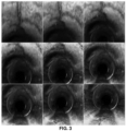
- FIG. 3 depicts a set of images serving as an input data to the system 100 of FIG. 1 , the set of images being specific to the liquid pipeline (e.g., sewer pipeline), in accordance with an embodiment of the present disclosure.
- images of a sewer pipeline are considered for better understanding of the embodiments described herein and such examples shall not be construed as limiting the scope of the present disclosure.
- Images of the sewer pipeline serving as an input data for the system and method of the present disclosure are obtained from available dataset source (e.g., refer
- the one or more hardware processors 104 extract one or more optimum frames (also referred as ⁇ best frames' and may be interchangeably used hereinafter) from the input data specific to the liquid pipeline.
- optimum frames also referred as ⁇ best frames' and may be interchangeably used hereinafter
- anomalous frames also referred as frames and interchangeably used herein
- corresponding log files are extracted from the video data wherein the frames are stored in various defect folders comprised in the database 108 of the memory 102.
- input may comprise a set of video data wherein multiple videos of the sewer pipeline may be received.
- appropriate video data is/are selected for frames extraction.
- the log file and video data are validated wherein delay is created for time and distance using delay creation technique(s) as known in the art.
- information from the log file is fetched and specific frames are extracted from the video data.
- the one or more optimum/best frames are extracted. For instance, consider a video data serving as an input.
- the specific frames which were extracted as mentioned above are then fed as an input to a frame selection/filtering technique (e.g., filtering technique(s) as known in the art) wherein the frame selection/filtering technique outputs a set of selected frames.
- a frame selection/filtering technique e.g., filtering technique(s) as known in the art
- one or more parameters such as average luminescence level, contrast level and blur index are estimated and based on the estimated parameters the one or more optimum/best frames are selected. More specifically, weighted sum of the estimated parameters is used to extract the one or more optimum/best frames.
- survey metadata information from initial frames and camera distance from start in all subsequent frames are extracted by the system 100, in one example embodiment.
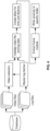
- FIG. 4 depicts a block diagram illustrating a method for frames extraction from the input data, using the system 100 of FIG. 1 , in accordance with an embodiment of the present disclosure.
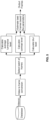
- FIG. 5 depicts a block diagram illustrating a method for extracting and selecting of one or more optimum frames from the input data, using the system 100 of FIG. 1 , in accordance with an embodiment of the present disclosure.
- FIG. 6 depicts one or more optimum frames extracted from the input data, using the system 100 of FIG. 1 , in accordance with an embodiment of the present disclosure.
- the one or more hardware processors 104 dehaze the one or more extracted optimum frames to obtain one or more dehazed images. It is imperative to improve the visibility for a given video/image(s) captured inside sewage water pipelines under challenging conditions such as non-uniform haze, non-uniform illumination due to artificial light sources and dynamic turbid water. This step is important because haze is primarily due to the light reflected by the medium back to the image capturing device (e.g., camera). Also, the light reflected by scene element(s) are partially absorbed by the medium itself.
- the image capturing device e.g., camera
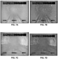
- the one or more dehazed images are obtained thereby enhancing the quality of the frames which can improve the accuracy of tasks like detecting cracks, sediments, etc., in one example embodiment.
- the step of dehazing the one or more extracted optimum frames to obtain the one or more dehazed images include: extracting one or more local properties, such as opacity and air-light for each pixel in the frames (or performing local properties extraction at a pixel level), wherein extraction of the one or more local properties results in obtaining an opacity map.
- FIGS. 7A through 7D depict the one or more dehazed images outputted by the system 100 of FIG. 1 , in accordance with an embodiment of the present disclosure.
- the one or more hardware processors 104 identify, from the one or more dehazed images, one or more liquid banks (water banks) and generate one or more contours based on the one or more identified liquid banks (e.g., the one or more identified water banks.
- One or more areas of liquid touching the banks of the liquid pipeline e.g., sewer pipeline, oil pipeline, natural gas pipeline, crude oil pipeline and the like
- liquid bank One or more areas of liquid touching the banks of the liquid pipeline (e.g., sewer pipeline, oil pipeline, natural gas pipeline, crude oil pipeline and the like) are detected which are indicative of the liquid banks (or portion of the pipeline alongside or where liquid deposit can be found is referred as liquid bank).
- FIG. 8 depicts an image with the one or more identified liquid banks (e.g., water banks) and contours generated thereof, using the system 100 of FIG. 1 , in accordance with an embodiment of the present disclosure. More specifically, FIG. 8 , with reference to FIGS. 1 through 7D , depicts an image with the one or more identified water banks and contours generated thereof, using the system 100 of FIG. 1 , in accordance with an embodiment of the present disclosure.
- the one or more hardware processors 104 detect a change in a liquid level from the one or more generated contours.
- Liquid level change detection helps get an accurate assessment of the functional health of pipelines (also referred as pipes and may be interchangeably used herein) and is totally reliant on image-based methods as compared to current flow/pressure-based methods.
- image-based methods For instance, water level change detection in sewer pipeline, water pipeline and the like helps get an accurate assessment of the functional health of pipelines (also referred as pipes and may be interchangeably used herein) and is totally reliant on image-based methods as compared to current flow/pressure-based methods.
- zoning to determine region of interest
- semantic segmentation to distinguish liquid (e.g., water) boundary from pipe
- determining the intersection of boundary lines and
- measuring the included angle to know the proportion vis-à-vis the circumference.
- the process discards non-standard lines which are off-center and progressively measures the change in angle beyond a threshold. Detection of liquid level (or water level) helps in detection of the center (vanishing point in the image). Relative depth can also be estimated with this approach, which can be useful in many use-cases (e.g., detect pose of the camera leveraging liquid line (or water line), liquid/water detection using visual sensor in confined noisy environment, etc.).
- the step of detecting a change in a liquid level (or water level from water pipeline/sewer pipeline, oil level in oil pipelines) from the one or more generated contours comprises fitting two or more lines in each of the one or more generated contours; determining one or more intersection points of the two or more lines; calculating an angle of intersection and generating a circle with radius R using the one or more intersection points of the two or more lines; calculating a segment intersection using the angle of intersection and the generated circle; and detecting the change in the liquid level based on the segment intersection.
- Line fitting e.g., geometry line fit technique
- the one or more intersection points of the two or more lines are determined wherein (i) an angle of intersection is calculated and (ii) a circle with radius R is generated using the one or more intersection points of the two or more lines.
- a segment intersection is calculated using the angle of intersection and the generated circle.
- the change in the liquid level is detected. In other words, best fit lines are determined for the liquid bank contours detected by segmentation model and then intersection point of these lines is determined.
- angle of intersection is calculated and a circle around intersection point is generated. Circle is a heuristic for diameter of the pipe and the angle of intersection approximates the segment covered by liquid. Area of segment of intersection point with the circle is calculated and liquid level in percentage is derived. Percentages of liquid level across multiple frames is tracked.
- detecting a change in a water level (or water level from water pipeline/sewer pipeline) from the one or more generated contours comprises fitting two or more lines in each of the one or more generated contours; determining one or more intersection points of the two or more lines; calculating an angle of intersection and generating a circle with radius R using the one or more intersection points of the two or more lines; calculating a segment intersection using the angle of intersection and the generated circle; and detecting the change in the water level based on the segment intersection.
- Line fitting e.g., geometry line fit technique
- the one or more intersection points of the two or more lines are determined wherein (i) an angle of intersection is calculated and (ii) a circle with radius R is generated using the one or more intersection points of the two or more lines.
- a segment intersection is calculated using the angle of intersection and the generated circle.
- the change in the water level is detected. In other words, best fit lines are determined for the water bank contours detected by segmentation model and then intersection point of these lines is determined.
- angle of intersection is calculated and a circle around intersection point is generated. Circle is a heuristic for diameter of the pipe and the angle of intersection approximates the segment covered by liquid. Area of segment of intersection point with the circle is calculated and water level in percentage is derived. Percentages of liquid level across multiple frames is tracked.
- FIGS. 9A-9B depict an image with a change in a liquid level (e.g., water level) being detected from the one or more generated contours, using the system 100 of FIG. 1 , in accordance with an embodiment of the present disclosure.
- a liquid level e.g., water level
- FIGS. 9A-9B depict an image with a change in a liquid level (e.g., water level) being detected from the one or more generated contours, using the system 100 of FIG. 1 , in accordance with an embodiment of the present disclosure.
- the above approach described herein for change in water level detection can be applied for other liquid types (e.g., oil, natural gas) and other fluid types (e.g., crude oil/petroleum products, etc.) as well by implementation of the systems and methods of the present disclosure.
- the one or more hardware processors 104 estimate a pose of the image capturing device based on (i) an angle of intersection, (ii) a segment intersection and (iii) a generated circle obtained from the one or more generated contours.
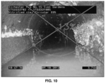
- Pose of the camera/image capturing device can be estimated by leveraging liquid (e.g., water) line, wherein water detection is performed using visual sensor(s) in confined noisy environment. More specifically, the pose of the image capturing device is estimated based on a deviation in an angle between the segment intersection and the generated circle obtained from the one or more generated contours, in one embodiment of the present disclosure.
- FIG. 10 depicts an image illustrating a pose of an image capturing device being estimated, using the system of FIG. 1 , in accordance with an embodiment of the present disclosure.
- the one or more hardware processors 104 identify a first set of objects in the liquid pipeline using the estimated pose.
- FIGS. 11A through 11D depict a set of images illustrating the first set of objects being identified in the liquid pipeline (e.g., sewer pipeline), using the system 100 of FIG. 1 , in accordance with an embodiment of the present disclosure. More specifically, FIGS. 11A through 11D , with reference to FIGS. 1 through 10 , depict a set of images illustrating the first set of objects being identified in the sewer pipeline, using the system 100 of FIG. 1 , in accordance with an embodiment of the present disclosure.
- the first set of identified objects are at least one of a structural object type and a functional object type, in one embodiment of the present disclosure.
- One of the first set of identified objects is depicted in FIG. 11B illustrating a curve like labeling in gray line representation, in one example embodiment of the present disclosure.
- Another identified object includes a white color like deposit on the right side of the pipeline as depicted in FIG. 11D , in another example embodiment of the present disclosure.
- Table 1 depicts exemplary first set of identified objects classified as a structural object type and/or a functional object type.
- the one or more hardware processors 104 identify one or more defects in the liquid pipeline (e.g., sewer pipeline, oil pipeline, natural gas pipeline, crude oil pipeline and the like) based on the first set of identified objects.
- the one or more hardware processors 104 classify the one or more defects into one or more categories.
- FIGS. 12A through 12D depict a set of images illustrating the one or more defects being identified in the liquid pipeline (e.g., sewer pipeline) based on the first set of identified objects and classified in one or more categories, using the system 100 of FIG.
- FIGS. 12A through 12D depict a set of images illustrating the one or more defects being identified in the sewer pipeline based on the first set of identified objects and classified in one or more categories, using the system 100 of FIG. 1 , in accordance with an embodiment of the present disclosure.
- the one or more defects are classified into the one or more categories such as, at least one of (a) one or more fractures, (b) one or more breaks, (c) one or more cracks.
- the one or more defects are identified as at least one of (a) one or more fractures, (b) one or more breaks, (c) one or more cracks based on a defect ratio area, in one example embodiment. For instance, fracture/cracks can be observed in FIGS. 12C and 12D , in one example embodiment.
- the one or more defects are identified using a semantic segmentation technique (as known in the art technique), in one example embodiment.
- That frame is masked and further refined to obtain a refined detected mask frame, wherein refining is performed to remove unnecessary noise comprised in the detected mask of the frame.
- various defect parameters are estimated/calculated for the one or more defects being identified/detected.
- the various parameters estimated/calculated include, for example, but are not limited to, rectangle area, defect area ratio by performing contour fitting, rectangle fitting like techniques as known in the art.
- it is checked whether a defect corresponds to a specific defect category/defect type. For instance, a defect is checked if it belongs to a break defect category. If it is a yes, then the defect is classified under break defect category.
- defect does not belong to a break defect category (if No)
- the defect is further checked if it belongs to a fracture defect category. If the defect is identified to be belonging to the fracture defect category, it is further checked whether the defect has multiple cracks/fractures. Else if no, it is further checked whether the defect is of a crack defect category. If multiple cracks/fractures are identified (if Yes), then the defect is classified under multiple cracks or multiple fractures category. If the defect does not have any multiple cracks/fractures (if No), then it is further checked whether it is a circumferential or a longitudinal defect and accordingly the defect is classified under say either circumferential/ longitudinal crack defect category or circumferential/longitudinal fracture defect category.
- the defect is a crack defect category, it is checked for whether the defect is circumferential or longitudinal defect category type and is accordingly categorized by the system 100 of FIG. 1 .
- region(s) of interest in the frame are identified from the segmentation step wherein contour fitting and best rectangle fitting is performed around it. Rectangle area and contour area are calculated, and defect area ratio is derived accordingly.
- predefined thresholds e.g., thresholding technique
- Rectangle aspect ratio is used to classify orientation of the defect contour such as longitudinal or circumferential and the like, in one example embodiment of the present disclosure.
- number of instances of defective contours in frame are determined to classify the defect as single or multiple instances.
- Defect(s) identified around a wall of the liquid pipeline are classified as one of (i) a longitudinal defect type or (ii) a circumferential defect type, in one example embodiment of the present disclosure.
- Defect(s) identified around one or more junctions of the liquid pipeline are classified as one or more junction types (e.g., a blocked junction, a semi-blocked junction, an unblocked junction.
- the defects identified around the one or more junctions of the liquid pipeline are based on a change in structural position of the one or more junctions, in one example embodiment of the present disclosure.
- Table 2 depicts example junction defects and corresponding description: Table 2 Type of Junction Defect Description Incorrect Position Position is either in lower half of pipe or is against the flow - Classified with respect to pose Intruding JN/CN (junction/connection or connects) intruding into the pipeline (or intruding into the sewer) Damaged There are breakages or other defects around JN/CN Blocked JN/CN is blocked
- the one or more hardware processors 104 compute a severity of the one or more identify defect types based on a location associated therewith.
- joint(s), displacement(s) is categorized/classified as second set of objects. Further, liquid/fluid level is classified/categorized under the first set of objects and change in liquid/fluid level is classified/categorized under the second set of objects, in one example embodiment of the present disclosure.
- Table 3 depicts various objects and domain-based rules being illustrated by way of examples: Table 3 Object Domain Based Rule(s) liquid/fluid (e.g., water as liquid) Level Level changes beyond 5% will be tracked - Rise in level can indicate blockages and dips can indicate leakages Junction /Connection Will be subclassified based on position and diameter - 3 o'clock / 9 o' 'clock position and larger diameter indicate Junction else Connection Joints Defects close to Joints ( ⁇ 0.2m) will be classified as Joint Defect to help prioritize maintenance Roots and Fractures/ Displacements Combination Rule - Presence of roots indicate fracture/displacement in pipes as well Holes and Spalling Combination Rule - Presence of holes is usually accompanied by spalling on the surrounding wall portion Generic Defects extending beyond 1 m are tracked as continuous defects to help prioritize maintenance Generic Surveys typically start at one manhole and finish at the next manhole, so all defects identified lie between start and finish manholes
- Systems and methods of the present disclosure implement a deep learning region bound approach for predicting/detecting the presence of junctions and connections in a frame.
- the one or more optimum/best frames extracted from the input data serve as an input for predicting/detecting the presence of junctions and connections in a frame, wherein a pre-trained model file (as known in the art) is utilized as an additional input.
- Regions of interests (RoIs) are identified and image pose is corrected considering the rotation of the image capturing device, wherein for a given frame/image, the pose for the image capturing device is provided as input. Once the pose of the image capturing device is corrected, (i) diameter of the detected/identified RoIs and (ii) projection angle of junction(s)/connection(s) are calculated.
- a corresponding RoI is categorized/classified as either a junction or a connection. More specifically, the RoIs are classified into junction or connection using heuristics based on material, size and orientation of the object in frame(s). This improves the method of the present disclosure by going beyond mere detection and actually sub-classifying them further as closed/blocked junctions, defective junctions and the like using granular classifiers (e.g., trained classifiers such as support vector machine, random forest, and the like).
- granular classifiers e.g., trained classifiers such as support vector machine, random forest, and the like.
- one or more joints are identified in the liquid pipeline (e.g., sewer pipeline, oil pipeline, natural gas pipeline, crude oil pipeline and the like) based on the extracted one or more optimal frames using a set of filters by: segmenting wall of the liquid pipeline (e.g., sewer pipeline, oil pipeline, natural gas pipeline, crude oil pipeline and the like) into one or more regions using a semantic segmentation technique (as known in the art technique) to obtain a plurality of regions of interest; applying a first pre-processing filter on the plurality of regions of interest to obtain a plurality of pre-processed regions of interest; applying, (i) a second pre-processing filter and (ii) a thresholding technique on the plurality of pre-processed regions of interest to obtain at least a subset of regions of interests; and applying a transformation technique on the subset of regions of interests to identify the one or more joints.
- a semantic segmentation technique as known in the art technique
- the one or more joints are identified in the liquid pipeline (e.g., sewer pipeline, oil pipeline, natural gas pipeline, crude oil pipeline and the like) based on the extracted one or more optimal frames using the set of filters by: segmenting wall regions of the liquid pipeline (e.g., sewer pipeline, oil pipeline, natural gas pipeline, crude oil pipeline and the like) using semantic segmentation technique to get the regions of interest, applying a pre-designed max-contrast filter (e.g., a first pre-processing filter) for enhancing the regions of interest; applying a pre-designed dark channel filter (e.g., a second pre-processing filter) and thresholding to get a subset of regions of interest, specifically the shadowed region and applying circle/oval detection algorithm (such as Hough transform) to detect the joints.
- a pre-designed max-contrast filter e.g., a first pre-processing filter
- a pre-designed dark channel filter e.g., a second pre-processing filter
- circle/oval detection algorithm such as
- Hough transforms are used to detect circle in the binary image generated from the thresholding step, wherein the result of performing Hough transformation is a binary output based on the presence of joint in the circle.
- the defect log serving as an output from all components of the system 100 are consolidated and header information such as manhole and water level at distance zero are marked. Further, water levels are processed wherein water levels with +/- x% (e.g., value of 'x' is 5 based on experiments conducted by the systems and methods of the present disclosure) are noted. It is to be understood by a person having ordinary skill in the art or person skilled in the art that the value of 'x' as +/- 5% shall not be construed as limiting the scope of the present disclosure.
- Identical frames are discarded if the frames are less than by a distance 'a' meter apart (e.g., value of 'a' is 0.2 based on experiments conducted by the systems and methods of the present disclosure). It is to be understood by a person having ordinary skill in the art or person skilled in the art that the value of 'a' as 0.2 shall not be construed as limiting the scope of the present disclosure. Defects that are within 'y' meter or joint(s) are noted for further analysis and processing (e.g., value of 'y' is 0.2 based on experiments conducted by the systems and methods of the present disclosure).
- Embodiments of the present disclosure enable users to upload images/videos of liquid pipeline (e.g., sewer pipelines, oil pipeline, natural gas pipeline, crude oil pipeline and the like serving as an input), wherein defect log information may be processed by the system 100 by implementing artificial intelligence-based techniques (as known in the art). Segments of interests are automatically identified and are further validated. The validation of the segments of interests may be performed by the system 100 by (i) using historical pattern of defects in liquid pipelines (e.g., sewer pipelines, oil pipeline, natural gas pipeline, crude oil pipeline and the like) inspected in the past, or (ii) obtaining one or more inputs from users (e.g., authorities).
- liquid pipelines e.g., sewer pipelines, oil pipeline, natural gas pipeline, crude oil pipeline and the like
- a report may be further generated, and the input may be marked as complete based on a review and validation of the segments.
- the defects in the report may be validated (e.g., by a user) and new defect types can be obtained from the users.
- a dashboard may be generated by the system 100 for users wherein global defect counts across all sites category wise may be made available to users for viewing and sharing inputs.
- the dashboard and data comprising in the dashboard may be further analyzed for comparison of sites which can be provided to users for viewing and analysis. Such comparison of sites may be generated by the system 100 upon selection of sites (wherein inputs may be received from users that depict selection of sites for comparison).
- the dashboard is further provided with other options wherein the users can select to view a drill down analysis of sites and pipelines.
- the system 100 further enables users to change system recommended priority for sites for various reasons (e.g., business reasons). Based on this, the workforce available and assignment can be reviewed by various stakeholders of the authorities and enable optimized maintenance schedule for priority sites.
- Embodiments of the present disclosure provide systems and methods that implement various techniques such as extraction of frames from input data (e.g., video data, images and the like), pre-processing the extracted frames by apply zoning, segmentation and frame filters to select best high quality frames, and the like.
- the systems and methods of the present disclosure may further use additional use case specific pre-processing and domain knowledge to identify the key frames for different streams of classifiers.
- the method includes processing step which includes extraction of meta-data about the survey from the corresponding video and frame data, loading pre-trained Artificial Intelligence, Deep Learning/Machine Learning (DL/ML) models comprised in the memory 102, computer vision (CV) techniques for detecting anomalies corresponding to different use cases such as manhole, liquid/fluid (e.g., water as liquid example) level, junction/connection, cracks/fractures/breaks, roots/holes, attached/floating deposits, and the like.
- processing step which includes extraction of meta-data about the survey from the corresponding video and frame data, loading pre-trained Artificial Intelligence, Deep Learning/Machine Learning (DL/ML) models comprised in the memory 102, computer vision (CV) techniques for detecting anomalies corresponding to different use cases such as manhole, liquid/fluid (e.g., water as liquid example) level, junction/connection, cracks/fractures/breaks, roots/holes, attached/floating deposits, and the like.
- liquid/fluid e
- the method of the present disclosure includes model (DL/ML) training that involves extracting data from videos, segregating them into train and test sets, annotating them with the class labels from the log provided, training them to detect frame /object level defects, as the case may be and test them using the validation set.
- the systems and method of the present disclosure make use of hierarchical classification scheme where category classification is required before granular sub-classification of object or anomaly can be derived.
- Heuristics based algorithms as known in the art are further implemented and applied by the systems and methods of the present disclosure for measuring the liquid/fluid (e.g., water as liquid example) level changes and in identification of Cracks/Fractures to determine instance counts and orientation.
- the present disclosure enables applying quantitative classification for specific defect classes to determine the severity and associated risk.
- the method of the present disclosure further includes Post-processing technique wherein after the multiple pass classification and scoring, frames are collated at post processing level for anomaly consolidation/rationalization / determination of severity.
- Post-processing level domain-based rules are applied for granular classification, elimination of duplicates, false positives, identifying structural defects around joints and qualifying continuous defects, and the like.
- reports may be generated by the system 100 (e.g., comma-separated values (CSV), Extensible Markup Language (XML) format, and the like) based on consolidated defect list and the same is stored in the memory 102.
- CSV comma-separated values
- XML Extensible Markup Language
- the hardware device can be any kind of device which can be programmed including e.g. any kind of computer like a server or a personal computer, or the like, or any combination thereof.
- the device may also include means which could be e.g. hardware means like e.g. an application-specific integrated circuit (ASIC), a field-programmable gate array (FPGA), or a combination of hardware and software means, e.g.
- ASIC application-specific integrated circuit
- FPGA field-programmable gate array
- the means can include both hardware means and software means.
- the method embodiments described herein could be implemented in hardware and software.
- the device may also include software means.
- the embodiments may be implemented on different hardware devices, e.g. using a plurality of CPUs.
- the embodiments herein can comprise hardware and software elements.
- the embodiments that are implemented in software include but are not limited to, firmware, resident software, microcode, etc.
- the functions performed by various components described herein may be implemented in other components or combinations of other components.
- a computer-usable or computer readable medium can be any apparatus that can comprise, store, communicate, propagate, or transport the program for use by or in connection with the instruction execution system, apparatus, or device.
- a computer-readable storage medium refers to any type of physical memory on which information or data readable by a processor may be stored.
- a computer-readable storage medium may store instructions for execution by one or more processors, including instructions for causing the processor(s) to perform steps or stages consistent with the embodiments described herein.
- the term "computer-readable medium” should be understood to include tangible items and exclude carrier waves and transient signals, i.e., be non-transitory. Examples include random access memory (RAM), read-only memory (ROM), volatile memory, nonvolatile memory, hard drives, CD ROMs, DVDs, flash drives, disks, and any other known physical storage media.
Landscapes
- Engineering & Computer Science (AREA)
- Theoretical Computer Science (AREA)
- General Physics & Mathematics (AREA)
- Physics & Mathematics (AREA)
- Computer Vision & Pattern Recognition (AREA)
- Multimedia (AREA)
- General Health & Medical Sciences (AREA)
- Health & Medical Sciences (AREA)
- Life Sciences & Earth Sciences (AREA)
- Artificial Intelligence (AREA)
- Data Mining & Analysis (AREA)
- Evolutionary Computation (AREA)
- Signal Processing (AREA)
- Immunology (AREA)
- Pathology (AREA)
- Biochemistry (AREA)
- Analytical Chemistry (AREA)
- Chemical & Material Sciences (AREA)
- Quality & Reliability (AREA)
- Evolutionary Biology (AREA)
- General Engineering & Computer Science (AREA)
- Bioinformatics & Computational Biology (AREA)
- Bioinformatics & Cheminformatics (AREA)
- Computing Systems (AREA)
- Databases & Information Systems (AREA)
- Medical Informatics (AREA)
- Software Systems (AREA)
- Image Analysis (AREA)
- Image Processing (AREA)
Claims (9)
- Prozessorimplementiertes Verfahren, umfassend:Empfangen, über einen oder mehrere Hardwareprozessoren, von Eingabedaten, die mindestens eines von Videodaten und einem oder mehreren Bildern von einer Bilderfassungsvorrichtung umfassen, wobei die Eingabedaten für eine Flüssigkeitsrohrleitung (202) spezifisch sind;Extrahieren, über den einen oder die mehreren Hardwareprozessoren, eines oder mehrerer optimaler Rahmen aus den für die Flüssigkeitsrohrleitung (204) spezifischen Eingabedaten;Dehazen des einen oder der mehreren extrahierten optimalen Rahmen, um ein oder mehrere dehazte Bilder (206) zu erhalten;Identifizieren, aus dem einen oder den mehreren dehazten Bildern, einer oder mehrerer identifizierter Flüssigkeitsbänke und Erzeugen einer oder mehrerer Konturen basierend auf der einen oder den mehreren identifizierten Flüssigkeitsbänken (208);Einpassen von zwei oder mehr Linien in jede der einen oder mehreren erzeugten Konturen;Bestimmen eines oder mehrerer Schnittpunkte der zwei oder mehr Linien;Berechnen eines Schnittwinkels der zwei oder mehr Linien;Erzeugen eines Kreises mit Radius R unter Verwendung des einen oder der mehreren Schnittpunkte der zwei oder mehr Linien; undBerechnen eines Segmentschnitts unter Verwendung des Schnittwinkels und des erzeugten Kreises;Detektieren einer Änderung eines Flüssigkeitspegels basierend auf dem Segmentschnitt der einen oder mehreren erzeugten Konturen (210);Schätzen einer Stellung der Bilderfassungsvorrichtung basierend auf (i) dem Schnittwinkel, (ii) dem Segmentschnitt und (iii) dem erzeugten Kreis, der aus der einen oder den mehreren erzeugten Konturen (212) erhalten wird;Identifizieren eines ersten Satzes von Objekten in der Flüssigkeitsrohrleitung unter Verwendung der geschätzten Stellung (214), wobei der erste Satz von Objekten mindestens eines von einem strukturellen Objekttyp und einem funktionellen Objekttyp ist;Identifizieren eines oder mehrerer Defekte in der Flüssigkeitsrohrleitung basierend auf dem ersten Satz von identifizierten Objekten (216), wobei der eine oder die mehreren Defekte mindestens eines von (a) einer oder mehreren Frakturen, (b) einem oder mehreren Brüchen und (c) einem oder mehreren Rissen umfassen, und wobei der eine oder die mehreren Defekte als mindestens eines von (a) der einen oder den mehreren Frakturen, (b) dem einen oder den mehreren Brüchen und (c) dem einen oder den mehreren Rissen basierend auf einem Defektverhältnisbereich unter Verwendung einer semantischen Segmentierungstechnik identifiziert werden, wobei der eine oder die mehreren Defekte, die um eine Wand der Flüssigkeitsrohrleitung herum identifiziert werden, als eines von (i) einem longitudinalen Defekttyp oder (ii) einem umlaufenden Defekttyp klassifiziert werden, wobei der eine oder die mehreren Defekte, die um eine oder mehrere Verbindungsstellen der Flüssigkeitsrohrleitung herum identifiziert werden, als ein oder mehrere Verbindungsstellentypen klassifiziert werden, wobei der eine oder die mehreren Defekte, die um die eine oder die mehreren Verbindungsstellen der Flüssigkeitsrohrleitung herum identifiziert werden, auf einer Änderung der strukturellen Position der einen oder der mehreren Verbindungsstellen basieren, und wobei eine oder mehrere Verbindungsstellen in der Flüssigkeitsrohrleitung basierend auf dem einen oder den mehreren extrahierten optimalen Rahmen unter Verwendung eines Satzes von Filtern identifiziert werden durch:Segmentieren der Wand der Flüssigkeitsrohrleitung in eine oder mehrere Regionen unter Verwendung der semantischen Segmentierungstechnik, um eine Mehrzahl von Bereichen von Interesse zu erhalten;Anwenden eines ersten Vorverarbeitungsfilters auf die Mehrzahl von Bereichen von Interesse, um eine Mehrzahl von vorverarbeiteten Bereichen von Interesse zu erhalten;Anwenden (i) eines zweiten Vorverarbeitungsfilters und einer Schwellenwertbildungstechnik auf die Mehrzahl von vorverarbeiteten Bereichen von Interesse, um mindestens eine Teilmenge von Bereichen von Interesse zu erhalten; undAnwenden einer Transformationstechnik auf die Teilmenge von Bereichen von Interesse, um die eine oder die mehreren Verbindungsstellen zu identifizieren, die als ein oder mehrere Verbindungsstellentypen klassifiziert sind; undKlassifizieren des einen oder der mehreren Defekte in eine oder mehrere Kategorien (218).
- Prozessorimplementiertes Verfahren nach Anspruch 1, wobei das Verfahren ferner das Berechnen einer Schwere des einen oder der mehreren identifizierten Defekte basierend auf einem damit assoziierten Ort umfasst.
- Prozessorimplementiertes Verfahren nach Anspruch 1, ferner umfassend:Detektieren, unter Verwendung eines Klassifizierungsmodells, einer zweiten Menge von Objekten, die sich von der ersten Menge von Objekten unterscheiden;Vorverarbeiten der zweiten Menge von Objekten, um eine Menge von vorverarbeiteten Objekten zu erhalten;Anwenden einer Menge von domänenbasierten Regeln auf die vorverarbeiteten Objekte, um mindestens eine Teilmenge der Menge von vorverarbeiteten Objekten zu erhalten; undKlassifizieren der Teilmenge der Menge von vorverarbeiteten Objekten.
- System (100), umfassend:einen Speicher (102), der Anweisungen speichert;eine oder mehrere Kommunikationsschnittstellen (106); undeinen oder mehrere Hardwareprozessoren (104), die über die eine oder die mehreren Kommunikationsschnittstellen (106) mit dem Speicher (102) gekoppelt sind, wobei der eine oder die mehreren Hardwareprozessoren (104) durch die Anweisungen konfiguriert sind zum:Empfangen von Eingabedaten, die mindestens eines von Videodaten und einem oder mehreren Bildern von einer Bilderfassungsvorrichtung umfassen, wobei die Eingabedaten für eine Flüssigkeitsrohrleitung spezifisch sind;Extrahieren eines oder mehrerer optimaler Rahmen aus den für die Flüssigkeitsrohrleitung spezifischen Eingabedaten;Dehazen des einen oder der mehreren extrahierten optimalen Rahmen, um ein oder mehrere dehazte Bilder zu erhalten;Identifizieren, aus dem einen oder den mehreren dehazten Bildern, einer oder mehrerer identifizierter Flüssigkeitsbänke und Erzeugen einer oder mehrerer Konturen basierend auf der einen oder den mehreren identifizierten Flüssigkeitsbänken;Einpassen von zwei oder mehr Linien in jede der einen oder mehreren erzeugten Konturen;Bestimmen eines oder mehrerer Schnittpunkte der zwei oder mehr Linien;Berechnen eines Schnittwinkels der zwei oder mehr Linien;Erzeugen eines Kreises mit Radius R unter Verwendung des einen oder der mehreren Schnittpunkte der zwei oder mehr Linien; undBerechnen eines Segmentschnitts unter Verwendung des Schnittwinkels und des erzeugten Kreises;Detektieren einer Änderung eines Flüssigkeitspegels basierend auf dem Segmentschnitt der einen oder mehreren erzeugten Konturen;Schätzen einer Stellung der Bilderfassungsvorrichtung basierend auf (i) dem Schnittwinkel, (ii) dem Segmentschnitt und (iii) dem erzeugten Kreis, der aus der einen oder den mehreren erzeugten Konturen erhalten wird;Identifizieren eines ersten Satzes von Objekten in der Flüssigkeitsrohrleitung unter Verwendung der geschätzten Stellung, wobei der erste Satz von Objekten mindestens eines von einem strukturellen Objekttyp und einem funktionellen Objekttyp ist;Identifizieren eines oder mehrerer Defekte in der Flüssigkeitsrohrleitung basierend auf dem ersten Satz von identifizierten Objekten, wobei der eine oder die mehreren Defekte mindestens eines von (a) einer oder mehreren Frakturen, (b) einem oder mehreren Brüchen und (c) einem oder mehreren Rissen umfassen, und wobei der eine oder die mehreren Defekte als mindestens eines von (a) der einen oder den mehreren Frakturen, (b) dem einen oder den mehreren Brüchen und (c) dem einen oder den mehreren Rissen basierend auf einem Defektverhältnisbereich unter Verwendung einer semantischen Segmentierungstechnik identifiziert werden, wobei der eine oder die mehreren Defekte, die um eine Wand der Flüssigkeitsrohrleitung herum identifiziert werden, als eines von (i) einem longitudinalen Defekttyp oder (ii) einem umlaufenden Defekttyp klassifiziert werden, wobei der eine oder die mehreren Defekte, die um eine oder mehrere Verbindungsstellen der Flüssigkeitsrohrleitung herum identifiziert werden, als ein oder mehrere Verbindungsstellentypen klassifiziert werden, wobei der eine oder die mehreren Defekte, die um die eine oder die mehreren Verbindungsstellen der Flüssigkeitsrohrleitung herum identifiziert werden, auf einer Änderung der strukturellen Position der einen oder der mehreren Verbindungsstellen basieren, und wobei eine oder mehrere Verbindungsstellen in der Flüssigkeitsrohrleitung basierend auf dem einen oder den mehreren extrahierten optimalen Rahmen unter Verwendung eines Satzes von Filtern identifiziert werden durch:Segmentieren der Wand der Flüssigkeitsrohrleitung in eine oder mehrere Regionen unter Verwendung der semantischen Segmentierungstechnik, um eine Mehrzahl von Bereichen von Interesse zu erhalten;Anwenden eines ersten Vorverarbeitungsfilters auf die Mehrzahl von Bereichen von Interesse, um eine Mehrzahl von vorverarbeiteten Bereichen von Interesse zu erhalten;Anwenden (i) eines zweiten Vorverarbeitungsfilters und einer Schwellenwertbildungstechnik auf die Mehrzahl von vorverarbeiteten Bereichen von Interesse, um mindestens eine Teilmenge von Bereichen von Interesse zu erhalten; undAnwenden einer Transformationstechnik auf die Teilmenge von Bereichen von Interesse, um die eine oder die mehreren Verbindungsstellen zu identifizieren, die als ein oder mehrere Verbindungsstellentypen klassifiziert sind; undKlassifizieren des einen oder der mehreren Defekte in eine oder mehrere Kategorien.
- System nach Anspruch 4, wobei der eine oder die mehreren Hardwareprozessoren ferner durch die Anweisungen konfiguriert sind, um eine Schwere des einen oder der mehreren identifizierten Defekte basierend auf einem damit assoziierten Ort zu berechnen.
- System nach Anspruch 4, wobei der eine oder die mehreren Hardwareprozessoren ferner durch die Anweisungen konfiguriert sind zum:Detektieren, unter Verwendung eines Klassifizierungsmodells, einer zweiten Menge von Objekten, die sich von der ersten Menge von Objekten unterscheiden;Vorverarbeiten der zweiten Menge von Objekten, um eine Menge von vorverarbeiteten Objekten zu erhalten;Anwenden einer Menge von domänenbasierten Regeln auf die vorverarbeiteten Objekte, um mindestens eine Teilmenge der Menge von vorverarbeiteten Objekten zu erhalten; undKlassifizieren der Teilmenge der Menge von vorverarbeiteten Objekten.
- Computerprogrammprodukt, umfassend ein nichtflüchtiges computerlesbares Medium mit einem darin verkörperten computerlesbaren Programm, wobei das computerlesbare Programm, wenn es auf einer Rechenvorrichtung ausgeführt wird, die Rechenvorrichtung veranlasst zum:Empfangen von Eingabedaten, die mindestens eines von Videodaten und einem oder mehreren Bildern von einer Bilderfassungsvorrichtung umfassen, wobei die Eingabedaten für eine Flüssigkeitsrohrleitung spezifisch sind;Extrahieren eines oder mehrerer optimaler Rahmen aus den für die Flüssigkeitsrohrleitung spezifischen Eingabedaten;Dehazen des einen oder der mehreren extrahierten optimalen Rahmen, um ein oder mehrere dehazte Bilder zu erhalten;Identifizieren, aus dem einen oder den mehreren dehazten Bildern, einer oder mehrerer identifizierter Flüssigkeitsbänke und Erzeugen einer oder mehrerer Konturen basierend auf der einen oder den mehreren identifizierten Flüssigkeitsbänken;Einpassen von zwei oder mehr Linien in jede der einen oder mehreren erzeugten Konturen;Bestimmen eines oder mehrerer Schnittpunkte der zwei oder mehr Linien;Berechnen eines Schnittwinkels der zwei oder mehr Linien;Erzeugen eines Kreises mit Radius R unter Verwendung des einen oder der mehreren Schnittpunkte der zwei oder mehr Linien; undBerechnen eines Segmentschnitts unter Verwendung des Schnittwinkels und des erzeugten Kreises;Detektieren einer Änderung eines Flüssigkeitspegels basierend auf dem Segmentschnitt der einen oder mehreren erzeugten Konturen;Schätzen einer Stellung der Bilderfassungsvorrichtung basierend auf (i) dem Schnittwinkel, (ii) dem Segmentschnitt und (iii) dem erzeugten Kreis, der aus der einen oder den mehreren erzeugten Konturen erhalten wird;Identifizieren eines ersten Satzes von Objekten in der Flüssigkeitsrohrleitung unter Verwendung der geschätzten Stellung, wobei der erste Satz von Objekten mindestens eines von einem strukturellen Objekttyp und einem funktionellen Objekttyp ist;Identifizieren eines oder mehrerer Defekte in der Flüssigkeitsrohrleitung basierend auf dem ersten Satz von identifizierten Objekten, wobei der eine oder die mehreren Defekte mindestens eines von (a) einer oder mehreren Frakturen, (b) einem oder mehreren Brüchen und (c) einem oder mehreren Rissen umfassen, und wobei der eine oder die mehreren Defekte als mindestens eines von (a) der einen oder den mehreren Frakturen, (b) dem einen oder den mehreren Brüchen und (c) dem einen oder den mehreren Rissen basierend auf einem Defektverhältnisbereich unter Verwendung einer semantischen Segmentierungstechnik identifiziert werden, wobei der eine oder die mehreren Defekte, die um eine Wand der Flüssigkeitsrohrleitung herum identifiziert werden, als eines von (i) einem longitudinalen Defekttyp oder (ii) einem umlaufenden Defekttyp klassifiziert werden, wobei der eine oder die mehreren Defekte, die um eine oder mehrere Verbindungsstellen der Flüssigkeitsrohrleitung herum identifiziert werden, als ein oder mehrere Verbindungsstellentypen klassifiziert werden, wobei der eine oder die mehreren Defekte, die um die eine oder die mehreren Verbindungsstellen der Flüssigkeitsrohrleitung herum identifiziert werden, auf einer Änderung der strukturellen Position der einen oder der mehreren Verbindungsstellen basieren, und wobei eine oder mehrere Verbindungsstellen in der Flüssigkeitsrohrleitung basierend auf dem einen oder den mehreren extrahierten optimalen Rahmen unter Verwendung eines Satzes von Filtern identifiziert werden durch:Segmentieren der Wand der Flüssigkeitsrohrleitung in eine oder mehrere Regionen unter Verwendung der semantischen Segmentierungstechnik, um eine Mehrzahl von Bereichen von Interesse zu erhalten;Anwenden eines ersten Vorverarbeitungsfilters auf die Mehrzahl von Bereichen von Interesse, um eine Mehrzahl von vorverarbeiteten Bereichen von Interesse zu erhalten;Anwenden (i) eines zweiten Vorverarbeitungsfilters und einer Schwellenwertbildungstechnik auf die Mehrzahl von vorverarbeiteten Bereichen von Interesse, um mindestens eine Teilmenge von Bereichen von Interesse zu erhalten; undAnwenden einer Transformationstechnik auf die Teilmenge von Bereichen von Interesse, um die eine oder die mehreren Verbindungsstellen zu identifizieren, die als ein oder mehrere Verbindungsstellentypen klassifiziert sind; undKlassifizieren des einen oder der mehreren Defekte in eine oder mehrere Kategorien.
- Computerprogrammprodukt, umfassend ein nichtflüchtiges computerlesbares Medium nach Anspruch 7, wobei das computerlesbare Programm, wenn es auf der Rechenvorrichtung ausgeführt wird, die Rechenvorrichtung veranlasst, eine Schwere des einen oder der mehreren identifizierten Defekte basierend auf einem damit assoziierten Ort zu berechnen.
- Computerprogrammprodukt, umfassend ein nichtflüchtiges computerlesbares Medium nach Anspruch 7, wobei das computerlesbare Programm, wenn es auf der Rechenvorrichtung ausgeführt wird, die Rechenvorrichtung veranlasst zum:Detektieren, unter Verwendung eines Klassifizierungsmodells, einer zweiten Menge von Objekten, die sich von der ersten Menge von Objekten unterscheiden;Vorverarbeiten der zweiten Menge von Objekten, um eine Menge von vorverarbeiteten Objekten zu erhalten;Anwenden einer Menge von domänenbasierten Regeln auf die vorverarbeiteten Objekte, um mindestens eine Teilmenge der Menge von vorverarbeiteten Objekten zu erhalten; undKlassifizieren der Teilmenge der Menge von vorverarbeiteten Objekten.
Applications Claiming Priority (1)
| Application Number | Priority Date | Filing Date | Title |
|---|---|---|---|
| IN202021032479 | 2020-07-29 |
Publications (3)
| Publication Number | Publication Date |
|---|---|
| EP3945458A1 EP3945458A1 (de) | 2022-02-02 |
| EP3945458B1 true EP3945458B1 (de) | 2024-04-10 |
| EP3945458C0 EP3945458C0 (de) | 2024-04-10 |
Family
ID=76601045
Family Applications (1)
| Application Number | Title | Priority Date | Filing Date |
|---|---|---|---|
| EP21181383.7A Active EP3945458B1 (de) | 2020-07-29 | 2021-06-24 | Identifizierung von defekttypen in flüssigrohrleitungen zur klassifizierung und berechnung des schweregrads davon |
Country Status (2)
| Country | Link |
|---|---|
| US (1) | US11790518B2 (de) |
| EP (1) | EP3945458B1 (de) |
Families Citing this family (11)
| Publication number | Priority date | Publication date | Assignee | Title |
|---|---|---|---|---|
| US20220284693A1 (en) * | 2021-03-05 | 2022-09-08 | The Boeing Company | Method, apparatus and computer program product for managing identified issues |
| US11625853B2 (en) * | 2021-04-12 | 2023-04-11 | Saudi Arabian Oil Company | Spot detection algorithm for external pipeline inspection applications |
| CN114742797A (zh) * | 2022-04-12 | 2022-07-12 | 清华大学 | 排水管道内壁全景图像的缺陷检测方法和图像采集机器人 |
| CN114937041B (zh) * | 2022-07-25 | 2022-10-25 | 聊城市博源节能科技有限公司 | 一种汽车发动机油路铜套缺陷检测方法及系统 |
| CN116416208A (zh) * | 2023-01-09 | 2023-07-11 | 中国科学院深圳先进技术研究院 | 管道缺陷检测方法、装置、电子设备及存储介质 |
| CN115932864B (zh) * | 2023-02-24 | 2023-08-01 | 深圳市博铭维技术股份有限公司 | 管道缺陷检测方法和管道缺陷检测装置 |
| CN116542964B (zh) * | 2023-06-06 | 2025-04-08 | 重庆大学 | 基于管道焊缝识别的管道缺陷定位方法 |
| US20250232422A1 (en) * | 2024-01-15 | 2025-07-17 | Hydromax USA, LLC | Method and apparatus for locating cross bores |
| CN118379652A (zh) * | 2024-04-22 | 2024-07-23 | 三峡金沙江川云水电开发有限公司 | 一种用于云雾环境的裂纹识别方法及装置 |
| JP7821361B1 (ja) * | 2025-05-21 | 2026-02-26 | 株式会社Rist | 学習モデルの生成方法、判定方法、及び情報処理装置 |
| CN120598889B (zh) * | 2025-05-27 | 2026-01-23 | 北京首创生态环保集团股份有限公司 | 一种用于排水管道检测视频的缺陷智能识别去重方法 |
Family Cites Families (10)
| Publication number | Priority date | Publication date | Assignee | Title |
|---|---|---|---|---|
| US8290294B2 (en) * | 2008-09-16 | 2012-10-16 | Microsoft Corporation | Dehazing an image using a three-dimensional reference model |
| US10072800B1 (en) * | 2011-10-17 | 2018-09-11 | Redzone Robotics, Inc. | Graphically representing a condition of infrastructure |
| US9518935B2 (en) * | 2013-07-29 | 2016-12-13 | Kla-Tencor Corporation | Monitoring changes in photomask defectivity |
| US20150244946A1 (en) * | 2013-11-04 | 2015-08-27 | Sos Agaian | Method and systems for thermal image / video measurements and processing |
| CN104568983B (zh) | 2015-01-06 | 2017-03-15 | 浙江工业大学 | 基于主动式全景视觉的管道内部缺陷检测装置及方法 |
| US20170323163A1 (en) | 2016-05-06 | 2017-11-09 | City Of Long Beach | Sewer pipe inspection and diagnostic system and method |
| US10937144B2 (en) * | 2017-11-09 | 2021-03-02 | Redzone Robotics, Inc. | Pipe feature identification using pipe inspection data analysis |
| US11598728B2 (en) * | 2018-05-04 | 2023-03-07 | Hydromax USA, LLC | Multi-sensor pipe inspection system and method |
| CN110599459A (zh) | 2019-08-14 | 2019-12-20 | 深圳市勘察研究院有限公司 | 基于深度学习的地下管网风险评估云系统 |
| AU2020435457A1 (en) * | 2020-03-09 | 2022-10-27 | Vapar Pty Ltd | Technology configured to enable fault detection and condition assessment of underground stormwater and sewer pipes |
-
2021
- 2021-06-24 EP EP21181383.7A patent/EP3945458B1/de active Active
- 2021-06-24 US US17/357,210 patent/US11790518B2/en active Active
Also Published As
| Publication number | Publication date |
|---|---|
| EP3945458C0 (de) | 2024-04-10 |
| US20220036541A1 (en) | 2022-02-03 |
| US11790518B2 (en) | 2023-10-17 |
| EP3945458A1 (de) | 2022-02-02 |
Similar Documents
| Publication | Publication Date | Title |
|---|---|---|
| US11790518B2 (en) | Identification of defect types in liquid pipelines for classification and computing severity thereof | |
| Wang et al. | Towards an automated condition assessment framework of underground sewer pipes based on closed-circuit television (CCTV) images | |
| Li et al. | A robust instance segmentation framework for underground sewer defect detection | |
| Halfawy et al. | Efficient algorithm for crack detection in sewer images from closed-circuit television inspections | |
| US20230101112A1 (en) | Technology configured to enable fault detection and condition assessment of underground stormwater and sewer pipes | |
| Li et al. | Automatic pavement-crack detection and segmentation based on steerable matched filtering and an active contour model | |
| Tsai et al. | Critical assessment of pavement distress segmentation methods | |
| Sollazzo et al. | Hybrid procedure for automated detection of cracking with 3D pavement data | |
| Koch et al. | A review on computer vision based defect detection and condition assessment of concrete and asphalt civil infrastructure | |
| Zhu et al. | Machine vision-based concrete surface quality assessment | |
| Yan et al. | A low-cost video-based pavement distress screening system for low-volume roads | |
| Dang et al. | Lightweight pixel-level semantic segmentation and analysis for sewer defects using deep learning | |
| O’Byrne et al. | An underwater lighting and turbidity image repository for analysing the performance of image-based non-destructive techniques | |
| US20130034305A1 (en) | Image-based crack quantification | |
| Wang et al. | Development and improvement of deep learning based automated defect detection for sewer pipe inspection using faster R-CNN | |
| US20170323163A1 (en) | Sewer pipe inspection and diagnostic system and method | |
| Tsai et al. | Comprehensive, quantitative crack detection algorithm performance evaluation system | |
| Zuo et al. | Classifying cracks at sub-class level in closed circuit television sewer inspection videos | |
| Guo et al. | Detection and classification of pipe defects based on pipe-extended feature pyramid network | |
| Guo et al. | Visual pattern recognition supporting defect reporting and condition assessment of wastewater collection systems | |
| Singh et al. | Segmentation technique for the detection of Micro cracks in solar cell using support vector machine | |
| Adu-Gyamfi et al. | Functional evaluation of pavement condition using a complete vision system | |
| Kumar et al. | Feasibility analysis of convolution neural network models for classification of concrete cracks in Smart City structures | |
| Hassan et al. | Damage detection and classification system for sewer inspection using convolutional neural networks based on deep learning | |
| Li et al. | A hybrid automatic thresholding approach using panchromatic imagery for rapid mapping of landslides |
Legal Events
| Date | Code | Title | Description |
|---|---|---|---|
| PUAI | Public reference made under article 153(3) epc to a published international application that has entered the european phase |
Free format text: ORIGINAL CODE: 0009012 |
|
| STAA | Information on the status of an ep patent application or granted ep patent |
Free format text: STATUS: THE APPLICATION HAS BEEN PUBLISHED |
|
| AK | Designated contracting states |
Kind code of ref document: A1 Designated state(s): AL AT BE BG CH CY CZ DE DK EE ES FI FR GB GR HR HU IE IS IT LI LT LU LV MC MK MT NL NO PL PT RO RS SE SI SK SM TR |
|
| STAA | Information on the status of an ep patent application or granted ep patent |
Free format text: STATUS: REQUEST FOR EXAMINATION WAS MADE |
|
| 17P | Request for examination filed |
Effective date: 20220718 |
|
| RBV | Designated contracting states (corrected) |
Designated state(s): AL AT BE BG CH CY CZ DE DK EE ES FI FR GB GR HR HU IE IS IT LI LT LU LV MC MK MT NL NO PL PT RO RS SE SI SK SM TR |
|
| REG | Reference to a national code |
Ref country code: DE Ref legal event code: R079 Ref country code: DE Ref legal event code: R079 Ref document number: 602021011503 Country of ref document: DE Free format text: PREVIOUS MAIN CLASS: G06K0009000000 Ipc: G06F0018241300 |
|
| GRAP | Despatch of communication of intention to grant a patent |
Free format text: ORIGINAL CODE: EPIDOSNIGR1 |
|
| STAA | Information on the status of an ep patent application or granted ep patent |
Free format text: STATUS: GRANT OF PATENT IS INTENDED |
|
| RIC1 | Information provided on ipc code assigned before grant |
Ipc: G06V 20/10 20220101ALI20231005BHEP Ipc: G06V 10/764 20220101ALI20231005BHEP Ipc: G06V 10/44 20220101ALI20231005BHEP Ipc: G06F 18/2413 20230101AFI20231005BHEP |
|
| INTG | Intention to grant announced |
Effective date: 20231023 |
|
| GRAS | Grant fee paid |
Free format text: ORIGINAL CODE: EPIDOSNIGR3 |
|
| GRAA | (expected) grant |
Free format text: ORIGINAL CODE: 0009210 |
|
| STAA | Information on the status of an ep patent application or granted ep patent |
Free format text: STATUS: THE PATENT HAS BEEN GRANTED |
|
| AK | Designated contracting states |
Kind code of ref document: B1 Designated state(s): AL AT BE BG CH CY CZ DE DK EE ES FI FR GB GR HR HU IE IS IT LI LT LU LV MC MK MT NL NO PL PT RO RS SE SI SK SM TR |
|
| REG | Reference to a national code |
Ref country code: GB Ref legal event code: FG4D |
|
| REG | Reference to a national code |
Ref country code: CH Ref legal event code: EP |
|
| REG | Reference to a national code |
Ref country code: DE Ref legal event code: R096 Ref document number: 602021011503 Country of ref document: DE |
|
| REG | Reference to a national code |
Ref country code: IE Ref legal event code: FG4D |
|
| U01 | Request for unitary effect filed |
Effective date: 20240410 |
|
| U07 | Unitary effect registered |
Designated state(s): AT BE BG DE DK EE FI FR IT LT LU LV MT NL PT SE SI Effective date: 20240415 |
|
| U20 | Renewal fee for the european patent with unitary effect paid |
Year of fee payment: 4 Effective date: 20240625 |
|
| PG25 | Lapsed in a contracting state [announced via postgrant information from national office to epo] |
Ref country code: IS Free format text: LAPSE BECAUSE OF FAILURE TO SUBMIT A TRANSLATION OF THE DESCRIPTION OR TO PAY THE FEE WITHIN THE PRESCRIBED TIME-LIMIT Effective date: 20240810 |
|
| PG25 | Lapsed in a contracting state [announced via postgrant information from national office to epo] |
Ref country code: HR Free format text: LAPSE BECAUSE OF FAILURE TO SUBMIT A TRANSLATION OF THE DESCRIPTION OR TO PAY THE FEE WITHIN THE PRESCRIBED TIME-LIMIT Effective date: 20240410 |
|
| PG25 | Lapsed in a contracting state [announced via postgrant information from national office to epo] |
Ref country code: GR Free format text: LAPSE BECAUSE OF FAILURE TO SUBMIT A TRANSLATION OF THE DESCRIPTION OR TO PAY THE FEE WITHIN THE PRESCRIBED TIME-LIMIT Effective date: 20240711 |
|
| PG25 | Lapsed in a contracting state [announced via postgrant information from national office to epo] |
Ref country code: ES Free format text: LAPSE BECAUSE OF FAILURE TO SUBMIT A TRANSLATION OF THE DESCRIPTION OR TO PAY THE FEE WITHIN THE PRESCRIBED TIME-LIMIT Effective date: 20240410 |
|
| PG25 | Lapsed in a contracting state [announced via postgrant information from national office to epo] |
Ref country code: PL Free format text: LAPSE BECAUSE OF FAILURE TO SUBMIT A TRANSLATION OF THE DESCRIPTION OR TO PAY THE FEE WITHIN THE PRESCRIBED TIME-LIMIT Effective date: 20240410 |
|
| PG25 | Lapsed in a contracting state [announced via postgrant information from national office to epo] |
Ref country code: PL Free format text: LAPSE BECAUSE OF FAILURE TO SUBMIT A TRANSLATION OF THE DESCRIPTION OR TO PAY THE FEE WITHIN THE PRESCRIBED TIME-LIMIT Effective date: 20240410 Ref country code: NO Free format text: LAPSE BECAUSE OF FAILURE TO SUBMIT A TRANSLATION OF THE DESCRIPTION OR TO PAY THE FEE WITHIN THE PRESCRIBED TIME-LIMIT Effective date: 20240710 Ref country code: IS Free format text: LAPSE BECAUSE OF FAILURE TO SUBMIT A TRANSLATION OF THE DESCRIPTION OR TO PAY THE FEE WITHIN THE PRESCRIBED TIME-LIMIT Effective date: 20240810 Ref country code: HR Free format text: LAPSE BECAUSE OF FAILURE TO SUBMIT A TRANSLATION OF THE DESCRIPTION OR TO PAY THE FEE WITHIN THE PRESCRIBED TIME-LIMIT Effective date: 20240410 Ref country code: GR Free format text: LAPSE BECAUSE OF FAILURE TO SUBMIT A TRANSLATION OF THE DESCRIPTION OR TO PAY THE FEE WITHIN THE PRESCRIBED TIME-LIMIT Effective date: 20240711 Ref country code: ES Free format text: LAPSE BECAUSE OF FAILURE TO SUBMIT A TRANSLATION OF THE DESCRIPTION OR TO PAY THE FEE WITHIN THE PRESCRIBED TIME-LIMIT Effective date: 20240410 Ref country code: RS Free format text: LAPSE BECAUSE OF FAILURE TO SUBMIT A TRANSLATION OF THE DESCRIPTION OR TO PAY THE FEE WITHIN THE PRESCRIBED TIME-LIMIT Effective date: 20240710 |
|
| REG | Reference to a national code |
Ref country code: DE Ref legal event code: R097 Ref document number: 602021011503 Country of ref document: DE |
|
| PG25 | Lapsed in a contracting state [announced via postgrant information from national office to epo] |
Ref country code: CZ Free format text: LAPSE BECAUSE OF FAILURE TO SUBMIT A TRANSLATION OF THE DESCRIPTION OR TO PAY THE FEE WITHIN THE PRESCRIBED TIME-LIMIT Effective date: 20240410 |
|
| PG25 | Lapsed in a contracting state [announced via postgrant information from national office to epo] |
Ref country code: RO Free format text: LAPSE BECAUSE OF FAILURE TO SUBMIT A TRANSLATION OF THE DESCRIPTION OR TO PAY THE FEE WITHIN THE PRESCRIBED TIME-LIMIT Effective date: 20240410 Ref country code: SK Free format text: LAPSE BECAUSE OF FAILURE TO SUBMIT A TRANSLATION OF THE DESCRIPTION OR TO PAY THE FEE WITHIN THE PRESCRIBED TIME-LIMIT Effective date: 20240410 |
|
| PG25 | Lapsed in a contracting state [announced via postgrant information from national office to epo] |
Ref country code: SM Free format text: LAPSE BECAUSE OF FAILURE TO SUBMIT A TRANSLATION OF THE DESCRIPTION OR TO PAY THE FEE WITHIN THE PRESCRIBED TIME-LIMIT Effective date: 20240410 |
|
| PG25 | Lapsed in a contracting state [announced via postgrant information from national office to epo] |
Ref country code: SM Free format text: LAPSE BECAUSE OF FAILURE TO SUBMIT A TRANSLATION OF THE DESCRIPTION OR TO PAY THE FEE WITHIN THE PRESCRIBED TIME-LIMIT Effective date: 20240410 Ref country code: SK Free format text: LAPSE BECAUSE OF FAILURE TO SUBMIT A TRANSLATION OF THE DESCRIPTION OR TO PAY THE FEE WITHIN THE PRESCRIBED TIME-LIMIT Effective date: 20240410 Ref country code: RO Free format text: LAPSE BECAUSE OF FAILURE TO SUBMIT A TRANSLATION OF THE DESCRIPTION OR TO PAY THE FEE WITHIN THE PRESCRIBED TIME-LIMIT Effective date: 20240410 Ref country code: CZ Free format text: LAPSE BECAUSE OF FAILURE TO SUBMIT A TRANSLATION OF THE DESCRIPTION OR TO PAY THE FEE WITHIN THE PRESCRIBED TIME-LIMIT Effective date: 20240410 Ref country code: MC Free format text: LAPSE BECAUSE OF FAILURE TO SUBMIT A TRANSLATION OF THE DESCRIPTION OR TO PAY THE FEE WITHIN THE PRESCRIBED TIME-LIMIT Effective date: 20240410 |
|
| PLBE | No opposition filed within time limit |
Free format text: ORIGINAL CODE: 0009261 |
|
| STAA | Information on the status of an ep patent application or granted ep patent |
Free format text: STATUS: NO OPPOSITION FILED WITHIN TIME LIMIT |
|
| 26N | No opposition filed |
Effective date: 20250113 |
|
| PG25 | Lapsed in a contracting state [announced via postgrant information from national office to epo] |
Ref country code: IE Free format text: LAPSE BECAUSE OF NON-PAYMENT OF DUE FEES Effective date: 20240624 |
|
| PGFP | Annual fee paid to national office [announced via postgrant information from national office to epo] |
Ref country code: GB Payment date: 20250617 Year of fee payment: 5 |
|
| U20 | Renewal fee for the european patent with unitary effect paid |
Year of fee payment: 5 Effective date: 20250624 |
|
| PGFP | Annual fee paid to national office [announced via postgrant information from national office to epo] |
Ref country code: CH Payment date: 20250701 Year of fee payment: 5 |
|
| PG25 | Lapsed in a contracting state [announced via postgrant information from national office to epo] |
Ref country code: CY Free format text: LAPSE BECAUSE OF FAILURE TO SUBMIT A TRANSLATION OF THE DESCRIPTION OR TO PAY THE FEE WITHIN THE PRESCRIBED TIME-LIMIT; INVALID AB INITIO Effective date: 20210624 |
|
| PG25 | Lapsed in a contracting state [announced via postgrant information from national office to epo] |
Ref country code: HU Free format text: LAPSE BECAUSE OF FAILURE TO SUBMIT A TRANSLATION OF THE DESCRIPTION OR TO PAY THE FEE WITHIN THE PRESCRIBED TIME-LIMIT; INVALID AB INITIO Effective date: 20210624 |