EP3945346A1 - Luftfahrzeugsystem und verfahren zur anzeige eines dreidimensionalen bedrohungsbilds - Google Patents
Luftfahrzeugsystem und verfahren zur anzeige eines dreidimensionalen bedrohungsbilds Download PDFInfo
- Publication number
- EP3945346A1 EP3945346A1 EP21188737.7A EP21188737A EP3945346A1 EP 3945346 A1 EP3945346 A1 EP 3945346A1 EP 21188737 A EP21188737 A EP 21188737A EP 3945346 A1 EP3945346 A1 EP 3945346A1
- Authority
- EP
- European Patent Office
- Prior art keywords
- threat
- dimensional
- aircraft
- processor
- image
- Prior art date
- Legal status (The legal status is an assumption and is not a legal conclusion. Google has not performed a legal analysis and makes no representation as to the accuracy of the status listed.)
- Pending
Links
Images



Classifications
-
- G—PHYSICS
- G01—MEASURING; TESTING
- G01S—RADIO DIRECTION-FINDING; RADIO NAVIGATION; DETERMINING DISTANCE OR VELOCITY BY USE OF RADIO WAVES; LOCATING OR PRESENCE-DETECTING BY USE OF THE REFLECTION OR RERADIATION OF RADIO WAVES; ANALOGOUS ARRANGEMENTS USING OTHER WAVES
- G01S13/00—Systems using the reflection or reradiation of radio waves, e.g. radar systems; Analogous systems using reflection or reradiation of waves whose nature or wavelength is irrelevant or unspecified
- G01S13/88—Radar or analogous systems specially adapted for specific applications
- G01S13/95—Radar or analogous systems specially adapted for specific applications for meteorological use
- G01S13/953—Radar or analogous systems specially adapted for specific applications for meteorological use mounted on aircraft
-
- G—PHYSICS
- G01—MEASURING; TESTING
- G01S—RADIO DIRECTION-FINDING; RADIO NAVIGATION; DETERMINING DISTANCE OR VELOCITY BY USE OF RADIO WAVES; LOCATING OR PRESENCE-DETECTING BY USE OF THE REFLECTION OR RERADIATION OF RADIO WAVES; ANALOGOUS ARRANGEMENTS USING OTHER WAVES
- G01S13/00—Systems using the reflection or reradiation of radio waves, e.g. radar systems; Analogous systems using reflection or reradiation of waves whose nature or wavelength is irrelevant or unspecified
- G01S13/88—Radar or analogous systems specially adapted for specific applications
- G01S13/89—Radar or analogous systems specially adapted for specific applications for mapping or imaging
-
- G—PHYSICS
- G01—MEASURING; TESTING
- G01S—RADIO DIRECTION-FINDING; RADIO NAVIGATION; DETERMINING DISTANCE OR VELOCITY BY USE OF RADIO WAVES; LOCATING OR PRESENCE-DETECTING BY USE OF THE REFLECTION OR RERADIATION OF RADIO WAVES; ANALOGOUS ARRANGEMENTS USING OTHER WAVES
- G01S7/00—Details of systems according to groups G01S13/00, G01S15/00, G01S17/00
- G01S7/02—Details of systems according to groups G01S13/00, G01S15/00, G01S17/00 of systems according to group G01S13/00
- G01S7/04—Display arrangements
- G01S7/06—Cathode-ray tube displays or other two dimensional or three-dimensional displays
- G01S7/20—Stereoscopic displays; Three-dimensional [3D] displays; Pseudo-3D displays
-
- G—PHYSICS
- G06—COMPUTING OR CALCULATING; COUNTING
- G06F—ELECTRIC DIGITAL DATA PROCESSING
- G06F3/00—Input arrangements for transferring data to be processed into a form capable of being handled by the computer; Output arrangements for transferring data from processing unit to output unit, e.g. interface arrangements
- G06F3/14—Digital output to display device ; Cooperation and interconnection of the display device with other functional units
-
- G—PHYSICS
- G06—COMPUTING OR CALCULATING; COUNTING
- G06T—IMAGE DATA PROCESSING OR GENERATION, IN GENERAL
- G06T15/00—Three-dimensional [3D] image rendering
-
- Y—GENERAL TAGGING OF NEW TECHNOLOGICAL DEVELOPMENTS; GENERAL TAGGING OF CROSS-SECTIONAL TECHNOLOGIES SPANNING OVER SEVERAL SECTIONS OF THE IPC; TECHNICAL SUBJECTS COVERED BY FORMER USPC CROSS-REFERENCE ART COLLECTIONS [XRACs] AND DIGESTS
- Y02—TECHNOLOGIES OR APPLICATIONS FOR MITIGATION OR ADAPTATION AGAINST CLIMATE CHANGE
- Y02A—TECHNOLOGIES FOR ADAPTATION TO CLIMATE CHANGE
- Y02A90/00—Technologies having an indirect contribution to adaptation to climate change
- Y02A90/10—Information and communication technologies [ICT] supporting adaptation to climate change, e.g. for weather forecasting or climate simulation
Definitions
- inventions of the inventive concepts disclosed herein are directed to a system.
- the system may include at least one display and at least one processor installed in an aircraft.
- the at least one processor may be communicatively coupled to the at least one display.
- the at least one processor may be configured to: obtain aircraft data associated with the aircraft; obtain an azimuth value associated with an azimuth; obtain radar data associated with at least one threat; generate a three-dimensional threat image based at least on the aircraft data, the azimuth value, and the radar data; and output the three-dimensional threat image as graphical data.
- the at least one display may be configured to display the three-dimensional threat image to a user.
- the three-dimensional threat image may depict a three-dimensional relationship between the aircraft and the at least one threat.
- the three-dimensional threat image may convey a range dimension, a lateral dimension extended perpendicularly from the azimuth, and a height dimension.
- inventions of the inventive concepts disclosed herein are directed to a method.
- the method may include: obtaining, by at least one processor installed in an aircraft and communicatively coupled to at least one display installed in the aircraft, aircraft data associated with the aircraft; obtaining, by the at least one processor, an azimuth value associated with an azimuth; obtaining, by the at least one processor, radar data associated with at least one threat; generating, by the at least one processor, a three-dimensional threat image based at least on the aircraft data, the azimuth value, and the radar data; outputting, by the at least one processor, the three-dimensional threat image as graphical data; and displaying, by the at least one display, the three-dimensional threat image to a user; wherein the three-dimensional threat image depicts a three-dimensional relationship between the aircraft and the at least one threat, wherein the three-dimensional threat image conveys a range dimension, a lateral dimension extended perpendicularly from the azimuth, and a height dimension.
- inventive concepts are not limited in their application to the details of construction and the arrangement of the components or steps or methodologies set forth in the following description or illustrated in the drawings.
- inventive concepts disclosed herein may be practiced without these specific details.
- well-known features may not be described in detail to avoid unnecessarily complicating the instant disclosure.
- inventive concepts disclosed herein are capable of other embodiments or of being practiced or carried out in various ways. Also, it is to be understood that the phraseology and terminology employed herein is for the purpose of description and should not be regarded as limiting.
- a letter following a reference numeral is intended to reference an embodiment of the feature or element that may be similar, but not necessarily identical, to a previously described element or feature bearing the same reference numeral (e.g., 1, 1a, 1b).
- reference numeral e.g. 1, 1a, 1b
- Such shorthand notations are used for purposes of convenience only, and should not be construed to limit the inventive concepts disclosed herein in any way unless expressly stated to the contrary.
- any reference to "one embodiment,” or “some embodiments” means that a particular element, feature, structure, or characteristic described in connection with the embodiment is included in at least one embodiment of the inventive concepts disclosed herein.
- the appearances of the phrase “in some embodiments” in various places in the specification are not necessarily all referring to the same embodiment, and embodiments of the inventive concepts disclosed may include one or more of the features expressly described or inherently present herein, or any combination of sub-combination of two or more such features, along with any other features which may not necessarily be expressly described or inherently present in the instant disclosure.
- embodiments of the inventive concepts disclosed herein may be directed to a system (e.g., an aircraft system) and a method configured to display at least one three-dimensional threat image.
- the three-dimensional threat image may be a three-dimensional weather threat image.
- the three-dimensional threat image may be a three-dimensional comprehensive airborne threat display image.
- Some embodiments may provide a way to display all relevant threats at a glance without increasing pilot workload.
- Some embodiments may provide a comprehensive display image capable of correlating all relevant horizontal and vertical information.
- This image may show relevant threats not just along the azimuth of interest but along a lateral area on either or both sides of the azimuth.
- this method can easily be integrated into threat objects.
- this method can give the flight crew more situational awareness in case they need to make a quick deviation decision.
- the displayed image may include simplified depictions of threats to reduce processor processing requirements; for example, threats may be simplified into a horizontal two-dimensional planar portion (e.g., at a base of the threat) and a vertical two-dimensional planar portion extending perpendicularly from the horizontal two-dimensional planar portion.
- the displayed image may be created by aligning a horizontal image along an azimuth (e.g., a selected azimuth) and by creating vertical image cutouts aligned to highest storm top portions of storm cores.
- threats may be displayed as a horizontal footprint of the threat at a low altitude and a dome-shaped cross-section extending from the footprint to a peak of the threat.
- An aircraft intercept altitude indicator may also be shown on each cutout to show the aircraft altitude at a time that the aircraft would be expected to intercept the storm.
- Some embodiments may provide significant cost savings and improve aircraft operating safety. For example, upgrading display systems in a cockpit can cost millions of dollars. Some embodiments may provide a way to show all relevant information including a vertical profile of a storm without hardware updates to existing displays. This may be especially true in case of current generation single-aisle aircraft where there is no dedicated vertical situation display (VSD). Providing all of the relevant information at a glance can enhance the situational awareness of the flight crew and may have a potential to improve safety.
- VSD vertical situation display
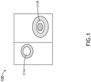
- FIG. 1 an exemplary embodiment of an overhead view of a horizontal two-dimensional threat image 100 depicting threats 213A, 213B is shown.
- the threats 213A, 213B may be weather threats, such as storm cells; however, in some embodiments, the horizontal two-dimensional threat image 100 may depict any type of threats, such as air traffic or other objects detectable by radar.
- the horizontal two-dimensional threat image 100 may be generated by at least one processor 602 of a radar computing device 308, as shown in FIG. 6 .
- the threats 213A, 213B may be weather threats, such as storm cells; however, in some embodiments, the three-dimensional threat image 200 may depict any type of threats, such as air traffic or other objects detectable by radar.
- the at least one threat 213A, 213B may be at least one storm threat
- the radar data may be weather radar data
- the three-dimensional threat image 200 may be a three-dimensional storm threat image, as shown in FIG. 2 .
- the three-dimensional threat image 200 may be generated by at least one processor 602 of a radar computing device 308, as shown in FIG. 6 .
- the three-dimensional threat image 200 may be generated based at least in part on the horizontal two-dimensional threat image 100 and/or radar data.
- the three-dimensional threat image 200 may be displayed by a display 402, as shown in FIG. 4 .
- the three-dimensional threat image 200 may depict a three-dimensional relationship between an aircraft 302 and the at least one threat 213A, 213B.
- the three-dimensional threat image 200 may convey a range dimension, a lateral dimension extended perpendicularly from an azimuth 204 (e.g., from both sides of the azimuth 204), and a height dimension.
- the three-dimensional threat image 200 may include: a graphical depiction of a height and width of each of the at least one threat 213A, 213B; a graphical depiction of an aircraft intercept altitude 210 for the aircraft 302 at each of the at least one threat 213A, 213B; a textual depiction of a threat height 208 (e.g., a storm top height) for each of the at least one threat 213A, 213B; a growth or decay indicator 212 (e.g., an upward pointing arrow for a growth indicator or a downward pointing arrow for a decay indicator) for each of the at least one threat 213A, 213B to indicate whether the threat 213A, 213B is growing or decaying; a graphical depiction of severity regions (e.g., a first severity region 214, a second severity region 216, and/or a third severity region 218) for each of the at least one threat 213A, 213B, each severity region associated with a
- a graphical depiction of each of the at least one threat 213A, 213B may include a horizontal two-dimensional planar portion and a vertical two-dimensional planar portion extending perpendicularly from the horizontal two-dimensional planar portion so as to reduce processing requirements as compared to a three-dimensionally rendered representation of surface contours for each of the at least one threat 213A, 213B.
- the three-dimensional threat image 200 has a lateral dimension of 40 nautical miles (nm) (e.g., 20 nm from each side of the aircraft 302) with a range of 100 nm and with a height of at least 33,000 feet; however, any suitable dimensions may be used.
- nm nautical miles
- a user and/or at least one processor of the system may be configured to set and/or adjust the dimensions.
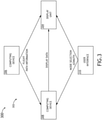
- the system may include an aircraft 302, which may include at least one user (e.g., flight crew and/or pilot(s)), at least one display unit computing device 304, at least one aircraft computing device 306, at least one radar computing device 308, and/or at least one user interface 310, some or all of which may be communicatively coupled at any given time.
- at least one user e.g., flight crew and/or pilot(s)
- at least one display unit computing device 304 e.g., at least one aircraft computing device 306, at least one radar computing device 308, and/or at least one user interface 310, some or all of which may be communicatively coupled at any given time.
- the at least one display unit computing device 304, the at least one aircraft computing device 306, the at least one radar computing device 308, and/or the at least one user interface 310 may be implemented as a single computing device or any number of computing devices configured to perform (e.g., collectively perform if more than one computing device) any or all of the operations disclosed throughout.
- the at least one display unit computing device 304, the at least one aircraft computing device 306, the at least one radar computing device 308, and/or the at least one user interface 310 may be installed in the aircraft 302.
- the user may be a pilot or crew member.
- the user may interface with the system 300 via the at least one user interface 310.
- the at least one user interface 310 may be implemented as any suitable user interface, such as a touchscreen (e.g., of the display unit computing device 304 and/or another display unit), a multipurpose control panel, a control panel integrated into a flight deck, a cursor control panel (CCP) (sometimes referred to as a display control panel (DCP)), a keyboard, a mouse, a trackpad, at least one hardware button, a switch, an eye tracking system, and/or a voice recognition system.
- a touchscreen e.g., of the display unit computing device 304 and/or another display unit
- CCP cursor control panel
- DCP display control panel
- the user interface 310 may be configured to receive at least one user input and to output the at least one user input to a computing device (e.g., 304, 306, and/or 308).
- a pilot of the aircraft 104 may be able to interface with the user interface 310 to: select an azimuth to be used for an azimuth value; engage (or disengage) a mode (e.g., a "comprehensive display mode") to cause the three-dimensional threat image 200 to be displayed; command an azimuth mode to be based on at least one of a track of the aircraft 302, a pilot selected azimuth, and/or aircraft information from the aircraft computing device 306 (e.g., a flight management system (FMS) or flight data computer).
- FMS flight management system
- such user inputs may be output to the radar computing device 308 and/or the display unit computing device 304.
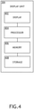
- the display unit computing device 304 may be implemented as any suitable computing device, such as a primary flight display (PFD) computing device and/or a multi-function window (MFW) display computing device. As shown in FIG. 4 , the display unit computing device 304 may include at least one display 402, at least one processor 404, at least one memory 406, and/or at least one storage 410, some or all of which may be communicatively coupled at any given time.
- PFD primary flight display
- MMW multi-function window
- the at least one processor 404 may include at least one central processing unit (CPU), at least one graphics processing unit (GPU), at least one field-programmable gate array (FPGA), at least one application specific integrated circuit (ASIC), at least one digital signal processor, at least one virtual machine (VM) running on at least one processor, and/or the like configured to perform (e.g., collectively perform) any of the operations disclosed throughout.
- the at least one processor 404 may include a CPU and a GPU configured to perform (e.g., collectively perform) any of the operations disclosed throughout.
- the processor 404 may be configured to run various software applications (e.g., a PFD application and/or an MFW application) or computer code stored (e.g., maintained) in a non-transitory computer-readable medium (e.g., memory 406 and/or storage 410) and configured to execute various instructions or operations.
- the processor 404 may be configured to perform any or all of the operations disclosed throughout.
- the processor 404 may be configured to: receive the aircraft data from the at least one aircraft computing device processor 502; and/or overlay the three-dimensional threat image 200 over other information from the aircraft data or to overlay the other information from the aircraft data over the three-dimensional threat image 200.
- the display 402 may be configured to display the three-dimensional threat image 200 to a user.
- the at least one aircraft computing device 306 may be implemented as any suitable computing device, such as an FMS computing device or a flight data computer.
- the at least one aircraft computing device 306 may include any or all of the elements, as shown in FIG. 5 .
- the aircraft computing device 306 may include at least one processor 502, at least one memory 504, and/or at least one storage 506, some or all of which may be communicatively coupled at any given time.
- the at least one processor 502 may include at least one central processing unit (CPU), at least one graphics processing unit (GPU), at least one field-programmable gate array (FPGA), at least one application specific integrated circuit (ASIC), at least one digital signal processor, at least one virtual machine (VM) running on at least one processor, and/or the like configured to perform (e.g., collectively perform) any of the operations disclosed throughout.
- the at least one processor 502 may include a CPU and a GPU configured to perform (e.g., collectively perform) any of the operations disclosed throughout.
- the processor 502 may be configured to run various software applications (e.g., an FMS application) or computer code stored (e.g., maintained) in a non-transitory computer-readable medium (e.g., memory 504 and/or storage 506) and configured to execute various instructions or operations.
- the processor 502 of the aircraft computing device 306 may be configured to perform any or all of the operations disclosed throughout.
- the processor 502 of the computing device 210A may be configured to: output aircraft data (e.g., FMS data, flight path data, inertial reference unit (IRU) data, flight data, and/or flight computer data) to the display unit computing device 304 and/or the radar computing device 308.
- aircraft data e.g., FMS data, flight path data, inertial reference unit (IRU) data, flight data, and/or flight computer data
- the at least one radar computing device 308 may be implemented as any suitable computing device, such as a weather radar computing device.
- the at least one radar computing device 308 may include any or all of the elements shown in FIG. 6 .
- the radar computing device 308 may include at least one radar antenna 601, at least one processor 602, at least one memory 604, and/or at least one storage 606, some or all of which may be communicatively coupled at any given time.
- the at least one processor 602 may include at least one central processing unit (CPU), at least one graphics processing unit (GPU), at least one field-programmable gate array (FPGA), at least one application specific integrated circuit (ASIC), at least one digital signal processor, at least one virtual machine (VM) running on at least one processor, and/or the like configured to perform (e.g., collectively perform) any of the operations disclosed throughout.
- the at least one processor 602 may include a CPU and a GPU configured to perform (e.g., collectively perform) any of the operations disclosed throughout.
- the processor 602 may be configured to run various software applications (e.g., a radar application) or computer code stored (e.g., maintained) in a non-transitory computer-readable medium (e.g., memory 604 and/or storage 606) and configured to execute various instructions or operations.
- the processor 602 of the radar computing device 308 may be configured to perform any or all of the operations disclosed throughout.
- the processor 602 may be configured to: obtain the aircraft data from the at least one aircraft computing device processor 502; obtain the azimuth value associated with the azimuth 204; obtain the radar data associated with the at least one threat 213A, 213B; generate the three-dimensional threat image 200 based at least on the aircraft data, the azimuth value, and the radar data; output the three-dimensional threat image 200 as the graphical data to the at least one display unit computing device processor 404; use the aircraft data to accurately compute weather information to be displayed; and/or based at least on a mode and/or azimuth user input
- At least one processor may be configured to (e.g., collectively configured to, if more than one processor): obtain aircraft data associated with the aircraft 302; obtain an azimuth value associated with an azimuth 204; obtain radar data associated with at least one threat 213A, 213B; generate a three-dimensional threat image 200 based at least on the aircraft data, the azimuth value, and/or the radar data; and/or output the three-dimensional threat image 200 as graphical data.
- At least one processor e.g., the at least one processor 404, the at least one processor 502, and/or the at least one processor 602 of the aircraft 302 may be configured to perform (e.g., collectively perform) any or all of the operations disclosed throughout.
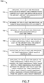
- an exemplary embodiment of a method 700 may include one or more of the following steps. Additionally, for example, some embodiments may include performing one or more instances of the method 700 iteratively, concurrently, and/or sequentially. Additionally, for example, at least some of the steps of the method 700 may be performed in parallel and/or concurrently. Additionally, in some embodiments, at least some of the steps of the method 700 may be performed non-sequentially.
- a step 702 may include obtaining, by at least one processor installed in an aircraft and communicatively coupled to at least one display installed in the aircraft, aircraft data associated with the aircraft.
- a step 704 may include obtaining, by the at least one processor, an azimuth value associated with an azimuth.
- a step 706 may include obtaining, by the at least one processor, radar data associated with at least one threat.
- a step 708 may include generating, by the at least one processor, a three-dimensional threat image based at least on the aircraft data, the azimuth value, and the radar data.
- a step 710 may include outputting, by the at least one processor, the three-dimensional threat image as graphical data.
- a step 712 may include displaying, by the at least one display, the three-dimensional threat image to a user, wherein the three-dimensional threat image depicts a three-dimensional relationship between the aircraft and the at least one threat, wherein the three-dimensional threat image conveys a range dimension, a lateral dimension extended perpendicularly from the azimuth, and a height dimension.
- method 700 may include any of the operations disclosed throughout.
- embodiments of the inventive concepts disclosed herein may be directed to a system (e.g., an aircraft system) and a method configured to display at least one three-dimensional threat image.
- a system e.g., an aircraft system
- a method configured to display at least one three-dimensional threat image.
- At least one non-transitory computer-readable medium may refer to as at least one non-transitory computer-readable medium (e.g., at least one computer-readable medium implemented as hardware; e.g., at least one non-transitory processor-readable medium, at least one memory (e.g., at least one nonvolatile memory, at least one volatile memory, or a combination thereof; e.g., at least one random-access memory, at least one flash memory, at least one read-only memory (ROM) (e.g., at least one electrically erasable programmable read-only memory (EEPROM)), at least one on-processor memory (e.g., at least one on-processor cache, at least one on-processor buffer, at least one on-processor flash memory, at least one on-processor EEPROM, or a combination thereof), or a combination thereof), at least one storage device (e.g., at least one hard-disk drive, at
- At least one means one or a plurality of; for example, “at least one” may comprise one, two, three, ..., one hundred, or more.
- one or more means one or a plurality of; for example, “one or more” may comprise one, two, three, ..., one hundred, or more.
- zero or more means zero, one, or a plurality of; for example, “zero or more” may comprise zero, one, two, three, ..., one hundred, or more.
- the methods, operations, and/or functionality disclosed may be implemented as sets of instructions or software readable by a device. Further, it is understood that the specific order or hierarchy of steps in the methods, operations, and/or functionality disclosed are examples of exemplary approaches. Based upon design preferences, it is understood that the specific order or hierarchy of steps in the methods, operations, and/or functionality can be rearranged while remaining within the scope of the inventive concepts disclosed herein.
- the accompanying claims may present elements of the various steps in a sample order, and are not necessarily meant to be limited to the specific order or hierarchy presented.
- embodiments of the methods according to the inventive concepts disclosed herein may include one or more of the steps described herein. Further, such steps may be carried out in any desired order and two or more of the steps may be carried out simultaneously with one another. Two or more of the steps disclosed herein may be combined in a single step, and in some embodiments, one or more of the steps may be carried out as two or more sub-steps. Further, other steps or sub-steps may be carried in addition to, or as substitutes to one or more of the steps disclosed herein.
Landscapes
- Engineering & Computer Science (AREA)
- Remote Sensing (AREA)
- Radar, Positioning & Navigation (AREA)
- Physics & Mathematics (AREA)
- General Physics & Mathematics (AREA)
- Computer Networks & Wireless Communication (AREA)
- Theoretical Computer Science (AREA)
- Electromagnetism (AREA)
- Aviation & Aerospace Engineering (AREA)
- Computer Graphics (AREA)
- Human Computer Interaction (AREA)
- General Engineering & Computer Science (AREA)
- Traffic Control Systems (AREA)
- Radar Systems Or Details Thereof (AREA)
Applications Claiming Priority (1)
| Application Number | Priority Date | Filing Date | Title |
|---|---|---|---|
| US16/943,847 US11543520B2 (en) | 2020-07-30 | 2020-07-30 | Aircraft system and method to display three-dimensional threat image |
Publications (1)
| Publication Number | Publication Date |
|---|---|
| EP3945346A1 true EP3945346A1 (de) | 2022-02-02 |
Family
ID=77155645
Family Applications (1)
| Application Number | Title | Priority Date | Filing Date |
|---|---|---|---|
| EP21188737.7A Pending EP3945346A1 (de) | 2020-07-30 | 2021-07-30 | Luftfahrzeugsystem und verfahren zur anzeige eines dreidimensionalen bedrohungsbilds |
Country Status (2)
| Country | Link |
|---|---|
| US (1) | US11543520B2 (de) |
| EP (1) | EP3945346A1 (de) |
Citations (1)
| Publication number | Priority date | Publication date | Assignee | Title |
|---|---|---|---|---|
| US9057773B1 (en) * | 2012-12-06 | 2015-06-16 | Rockwell Collins, Inc. | Weather information display system and method |
Family Cites Families (21)
| Publication number | Priority date | Publication date | Assignee | Title |
|---|---|---|---|---|
| US5198819A (en) | 1992-03-02 | 1993-03-30 | Thermwood Corporation | Weather radar display system |
| US7205928B1 (en) | 2006-05-31 | 2007-04-17 | Honeywell International Inc. | Automatic weather radar system and method |
| US8095314B2 (en) | 2006-10-04 | 2012-01-10 | Embry-Riddle Aeronautical University, Inc. | Generation of four dimensional grid of probabilistic hazards for use by decision support tools |
| US7688254B2 (en) | 2008-06-27 | 2010-03-30 | Honeywell International, Inc. | Display of high-cruise-altitude weather |
| FR2944596B1 (fr) | 2009-04-21 | 2011-06-03 | Thales Sa | Dispositif de visualisation pour aeronef comprenant des moyens d'affichage des tendances d'evolution meteorologique |
| US8111186B2 (en) | 2009-12-17 | 2012-02-07 | Honeywell International Inc. | Systems and methods for infering hail and lightning using an airborne weather radar volumetric buffer |
| US9823347B1 (en) | 2014-03-12 | 2017-11-21 | Rockwell Collins, Inc. | Weather radar system and method for high altitude crystal warning interface |
| US8681021B1 (en) | 2011-09-29 | 2014-03-25 | Rockwell Collins, Inc. | System, apparatus, and method for generating a lateral meteorological profile on an aircraft display unit |
| US10037124B2 (en) | 2014-07-08 | 2018-07-31 | Honeywell International Inc. | Vertical profile display including weather icons |
| US9710218B2 (en) | 2014-07-08 | 2017-07-18 | Honeywell International Inc. | Vertical profile display including hazard band indication |
| US10495783B2 (en) | 2014-07-08 | 2019-12-03 | Honeywell International Inc. | Vertical profile display including weather blocks |
| US9958573B2 (en) | 2014-08-11 | 2018-05-01 | The Boeing Company | 4D volumetric weather data processing and display |
| US10580312B2 (en) | 2015-07-24 | 2020-03-03 | Yamasee Ltd. | Method and system for obtaining and presenting turbulence data via communication devices located on airplanes |
| US10605912B1 (en) | 2015-09-30 | 2020-03-31 | Rockwell Collins, Inc. | Storm top adaptive beam scan |
| US10302815B1 (en) | 2015-10-01 | 2019-05-28 | Rockwell Collins, Inc. | System and method of integrating global convective weather |
| EP3296697B1 (de) | 2016-09-14 | 2020-08-26 | Honeywell International Inc. | Anzeigevorrichtung zur vertikale darstellung von vorhergesagtem wetter |
| US10453351B2 (en) * | 2017-07-17 | 2019-10-22 | Aurora Flight Sciences Corporation | System and method for detecting obstacles in aerial systems |
| US10247821B1 (en) | 2017-08-04 | 2019-04-02 | Rockwell Collins, Inc. | Panoramic weather radar display system for aircraft |
| US10930165B2 (en) | 2017-10-16 | 2021-02-23 | Honeywell International Inc. | Enhanced flight efficiency through smart automation for on-board weather update |
| US10209122B1 (en) | 2017-10-31 | 2019-02-19 | Honeywell International Inc. | Systems and methods for generating avionic displays including forecast overpressure event symbology |
| US11054280B2 (en) | 2018-11-30 | 2021-07-06 | International Business Machines Corporation | Displaying weather-based flight information in vertical profile |
-
2020
- 2020-07-30 US US16/943,847 patent/US11543520B2/en active Active
-
2021
- 2021-07-30 EP EP21188737.7A patent/EP3945346A1/de active Pending
Patent Citations (1)
| Publication number | Priority date | Publication date | Assignee | Title |
|---|---|---|---|---|
| US9057773B1 (en) * | 2012-12-06 | 2015-06-16 | Rockwell Collins, Inc. | Weather information display system and method |
Also Published As
| Publication number | Publication date |
|---|---|
| US20220035025A1 (en) | 2022-02-03 |
| US11543520B2 (en) | 2023-01-03 |
Similar Documents
| Publication | Publication Date | Title |
|---|---|---|
| US9501936B2 (en) | Aircraft systems and methods for displaying spacing information | |
| EP2884478B1 (de) | System und Verfahren zur textuellen und grafischen Darstellung von Flugverkehrskontroll-Sprachinformationen | |
| US9752893B2 (en) | Onboard aircraft systems and methods to identify moving landing platforms | |
| US20250054399A1 (en) | System and method to display view of airport moving map depicting runway overrun awareness and alerting system (roaas)-based indicators | |
| US9558674B2 (en) | Aircraft systems and methods to display enhanced runway lighting | |
| US10170010B1 (en) | Display of traffic overlaid on aeronautical chart | |
| CN106477057B (zh) | 用于改善关于旋翼机系统的意料之外的偏航的态势感知的方法和系统 | |
| US12091189B2 (en) | Systems and methods for enabling user control over use of aircraft sensors located onboard an aircraft | |
| US11501647B2 (en) | Estimated wake turbulence trail for aircraft system | |
| US10971020B1 (en) | Aircraft system and method to provide linear map of traffic | |
| EP3696512B1 (de) | Korrelatives anzeigesystem mit entstörten anzeigen für flugzeuge | |
| EP3734573B1 (de) | Grafischer geschwindigkeitsleistungsmonitor mit flugintervallverwaltung | |
| US11543520B2 (en) | Aircraft system and method to display three-dimensional threat image | |
| EP3971868B1 (de) | Flugzeugsystem und verfahren zur anzeige von luftverkehrsindikatoren | |
| US11081011B1 (en) | Aircraft system and method to provide graphical threshold range indicator | |
| EP4155772A1 (de) | System und verfahren zur auswahl und anzeige eines priorisierten vertikalen azimutscheibenradarbildes | |
| US9454800B2 (en) | System for representing cartographic indications at multiple scales | |
| US20250044810A1 (en) | Runtime assurance system for manual and automated landings | |
| EP4134706A1 (de) | System und verfahren zur anzeige eines flugzeugs mit relativem sturmbild von oben | |
| EP3901757A1 (de) | Flugzeugsystem und verfahren zum bewegen eines cursors in eine standardposition mit hardware-taste | |
| EP4210024A1 (de) | Systeme und verfahren zur ermöglichung der benutzersteuerung über die verwendung von flugzeugsensoren an bord eines flugzeugs | |
| US20200342773A1 (en) | Method and electronic device for managing the display of an aircraft flight profile with selection of suitable resolution(s) of field data base(s), related computer program and electronic display system | |
| EP4166985A1 (de) | System und verfahren zur anpassung oder unterdrückung der windscheralarmschwelle für wetterradar | |
| Anttila et al. | Cockpit and mission system modernization | |
| Terry et al. | Multimission helicopter cockpit displays |
Legal Events
| Date | Code | Title | Description |
|---|---|---|---|
| PUAI | Public reference made under article 153(3) epc to a published international application that has entered the european phase |
Free format text: ORIGINAL CODE: 0009012 |
|
| STAA | Information on the status of an ep patent application or granted ep patent |
Free format text: STATUS: THE APPLICATION HAS BEEN PUBLISHED |
|
| AK | Designated contracting states |
Kind code of ref document: A1 Designated state(s): AL AT BE BG CH CY CZ DE DK EE ES FI FR GB GR HR HU IE IS IT LI LT LU LV MC MK MT NL NO PL PT RO RS SE SI SK SM TR |
|
| STAA | Information on the status of an ep patent application or granted ep patent |
Free format text: STATUS: REQUEST FOR EXAMINATION WAS MADE |
|
| 17P | Request for examination filed |
Effective date: 20220728 |
|
| RBV | Designated contracting states (corrected) |
Designated state(s): AL AT BE BG CH CY CZ DE DK EE ES FI FR GB GR HR HU IE IS IT LI LT LU LV MC MK MT NL NO PL PT RO RS SE SI SK SM TR |
|
| STAA | Information on the status of an ep patent application or granted ep patent |
Free format text: STATUS: EXAMINATION IS IN PROGRESS |
|
| 17Q | First examination report despatched |
Effective date: 20241211 |