EP3945306A1 - Gas analysis system and gas analysis method - Google Patents
Gas analysis system and gas analysis method Download PDFInfo
- Publication number
- EP3945306A1 EP3945306A1 EP21188337.6A EP21188337A EP3945306A1 EP 3945306 A1 EP3945306 A1 EP 3945306A1 EP 21188337 A EP21188337 A EP 21188337A EP 3945306 A1 EP3945306 A1 EP 3945306A1
- Authority
- EP
- European Patent Office
- Prior art keywords
- component
- laser light
- phase
- amplitude
- measurement target
- Prior art date
- Legal status (The legal status is an assumption and is not a legal conclusion. Google has not performed a legal analysis and makes no representation as to the accuracy of the status listed.)
- Granted
Links
Images



Classifications
-
- G—PHYSICS
- G01—MEASURING; TESTING
- G01N—INVESTIGATING OR ANALYSING MATERIALS BY DETERMINING THEIR CHEMICAL OR PHYSICAL PROPERTIES
- G01N21/00—Investigating or analysing materials by the use of optical means, i.e. using sub-millimetre waves, infrared, visible or ultraviolet light
- G01N21/17—Systems in which incident light is modified in accordance with the properties of the material investigated
- G01N21/25—Colour; Spectral properties, i.e. comparison of effect of material on the light at two or more different wavelengths or wavelength bands
- G01N21/31—Investigating relative effect of material at wavelengths characteristic of specific elements or molecules, e.g. atomic absorption spectrometry
- G01N21/39—Investigating relative effect of material at wavelengths characteristic of specific elements or molecules, e.g. atomic absorption spectrometry using tunable lasers
-
- G—PHYSICS
- G01—MEASURING; TESTING
- G01N—INVESTIGATING OR ANALYSING MATERIALS BY DETERMINING THEIR CHEMICAL OR PHYSICAL PROPERTIES
- G01N21/00—Investigating or analysing materials by the use of optical means, i.e. using sub-millimetre waves, infrared, visible or ultraviolet light
- G01N21/17—Systems in which incident light is modified in accordance with the properties of the material investigated
- G01N21/59—Transmissivity
- G01N21/61—Non-dispersive gas analysers
-
- G—PHYSICS
- G01—MEASURING; TESTING
- G01N—INVESTIGATING OR ANALYSING MATERIALS BY DETERMINING THEIR CHEMICAL OR PHYSICAL PROPERTIES
- G01N21/00—Investigating or analysing materials by the use of optical means, i.e. using sub-millimetre waves, infrared, visible or ultraviolet light
- G01N21/17—Systems in which incident light is modified in accordance with the properties of the material investigated
- G01N21/25—Colour; Spectral properties, i.e. comparison of effect of material on the light at two or more different wavelengths or wavelength bands
- G01N21/31—Investigating relative effect of material at wavelengths characteristic of specific elements or molecules, e.g. atomic absorption spectrometry
-
- G—PHYSICS
- G01—MEASURING; TESTING
- G01J—MEASUREMENT OF INTENSITY, VELOCITY, SPECTRAL CONTENT, POLARISATION, PHASE OR PULSE CHARACTERISTICS OF INFRARED, VISIBLE OR ULTRAVIOLET LIGHT; COLORIMETRY; RADIATION PYROMETRY
- G01J3/00—Spectrometry; Spectrophotometry; Monochromators; Measuring colours
- G01J3/28—Investigating the spectrum
- G01J3/42—Absorption spectrometry; Double beam spectrometry; Flicker spectrometry; Reflection spectrometry
- G01J3/433—Modulation spectrometry; Derivative spectrometry
-
- G—PHYSICS
- G01—MEASURING; TESTING
- G01N—INVESTIGATING OR ANALYSING MATERIALS BY DETERMINING THEIR CHEMICAL OR PHYSICAL PROPERTIES
- G01N21/00—Investigating or analysing materials by the use of optical means, i.e. using sub-millimetre waves, infrared, visible or ultraviolet light
- G01N21/17—Systems in which incident light is modified in accordance with the properties of the material investigated
- G01N21/25—Colour; Spectral properties, i.e. comparison of effect of material on the light at two or more different wavelengths or wavelength bands
- G01N21/31—Investigating relative effect of material at wavelengths characteristic of specific elements or molecules, e.g. atomic absorption spectrometry
- G01N21/39—Investigating relative effect of material at wavelengths characteristic of specific elements or molecules, e.g. atomic absorption spectrometry using tunable lasers
- G01N2021/396—Type of laser source
- G01N2021/399—Diode laser
-
- G—PHYSICS
- G01—MEASURING; TESTING
- G01N—INVESTIGATING OR ANALYSING MATERIALS BY DETERMINING THEIR CHEMICAL OR PHYSICAL PROPERTIES
- G01N2201/00—Features of devices classified in G01N21/00
- G01N2201/06—Illumination; Optics
- G01N2201/061—Sources
- G01N2201/06113—Coherent sources; lasers
- G01N2201/0612—Laser diodes
-
- G—PHYSICS
- G01—MEASURING; TESTING
- G01N—INVESTIGATING OR ANALYSING MATERIALS BY DETERMINING THEIR CHEMICAL OR PHYSICAL PROPERTIES
- G01N2201/00—Features of devices classified in G01N21/00
- G01N2201/06—Illumination; Optics
- G01N2201/068—Optics, miscellaneous
-
- G—PHYSICS
- G01—MEASURING; TESTING
- G01N—INVESTIGATING OR ANALYSING MATERIALS BY DETERMINING THEIR CHEMICAL OR PHYSICAL PROPERTIES
- G01N2201/00—Features of devices classified in G01N21/00
- G01N2201/06—Illumination; Optics
- G01N2201/069—Supply of sources
- G01N2201/0691—Modulated (not pulsed supply)
-
- G—PHYSICS
- G01—MEASURING; TESTING
- G01N—INVESTIGATING OR ANALYSING MATERIALS BY DETERMINING THEIR CHEMICAL OR PHYSICAL PROPERTIES
- G01N2201/00—Features of devices classified in G01N21/00
- G01N2201/12—Circuits of general importance; Signal processing
- G01N2201/121—Correction signals
Definitions
- the present invention generally relates to a gas analysis system and a gas analysis method.
- Wavelength-modulation spectroscopy is a technique of irradiating a laser light modulated by a modulation frequency f to a measurement target gas and measuring a concentration of the measurement target gas based on a second-order harmonic component (2f component) obtained by detecting the laser light upon its transmission through the measurement target gas.
- wavelength-modulation spectroscopy the concentration of the measurement target gas is often measured upon calculating a ratio of the 2f component to a component (1f component) of the modulation frequency f that is detected and standardizing a light reception amount. This is to reduce an effect of fluctuations in the light reception amount of the laser light due to factors other than the measurement target gas.
- wavelength-modulation spectroscopy is also sometimes referred to as 2f detection.
- Patent literature 1 below discloses one example of a conventional gas analysis system that uses wavelength-modulation spectroscopy to measure a gas concentration.
- Patent Literature 1 WO 2017/014097 A1
- optical interference noise may be generated when the laser light passes through a lens or other optical element, a window, a thin film, or the like.
- This optical interference noise arises due to, for example, interference caused by the laser light upon undergoing multiple reflection inside an optical element or the like, and a magnitude thereof changes periodically depending on a wavelength of the laser light. For example, just as a transmittance of a Fabry-Pérot etalon becomes periodic relative to wavelength, the magnitude of the optical interference noise also becomes periodic relative to the wavelength.
- optical interference noise there is a problem of a worsened detection limit of the concentration of the measurement target gas.
- One or more embodiments provide a gas analysis system and a gas analysis method that can improve a detection limit of a concentration of a measurement target gas.
- a gas analysis system (1) includes: a light-emitting element (13) that emits a laser light modulated by a predetermined modulation frequency (f); a light-receiving element (17) that receives the laser light upon the laser light passing through a measurement target gas (GS); and a signal processing device (20) that calculates a concentration of the measurement target gas based on a magnitude of a third component obtained by removing, from a first component that is a component having an N-frequency, meaning a frequency n times (n being an integer no less than 2) the modulation frequency included in a received signal output from the light-receiving element, a second component that is a component, of the same frequency as the first component, of optical interference noise arising on an optical path of the laser light from the light-emitting element to the light-receiving element.
- the gas analysis system is provided with a detector (19) that detects an amplitude (R 2f ) and a phase ( ⁇ 2f ) of the first component included in the received signal
- the signal processing device is provided with a storage (21) that stores an amplitude (R 0 , R 02f ) and a phase ( ⁇ 0 , ⁇ 02f ) of the second component and a processor that calculates the third component by using the amplitude and the phase of the first component detected by the detector and the amplitude and the phase of the second component stored in the storage to perform a computation of removing the second component from the first component.
- the detector detects, in addition to the first component, a fundamental component that is a component having the same frequency as the modulation frequency included in the received signal, and the processor calculates the concentration of the measurement target gas based on a ratio (R' 2f /R 1f ) of an amplitude (R' 2f ) of the third component to an amplitude (Rif) of the fundamental component.
- the amplitude and the phase of the second component stored in the storage are an amplitude and a phase of the first component detected by the detector at a time when the measurement target gas is not present on the optical path of the laser light or a state where the concentration of the measurement target gas on the optical path of the laser light is sufficiently low, for example lower than a predetermined value.
- the amplitude and the phase of the second component stored in the storage are an amplitude and a phase obtained by performing a predetermined computation using an amplitude and a phase of the first component detected by the detector at a time when the measurement target gas is present on the optical path of the laser light at a known first concentration and an amplitude and a phase of the first component detected by the detector at a time when the measurement target gas is present on the optical path of the laser light at a known second concentration.
- the amplitude and the phase of the second component stored in the storage are an amplitude and a phase of the first component detected by the detector at a time when an optical path length of the laser light is set to a reference length prescribed in advance
- the processor calculates the third component by performing a computation of removing the second component from the first component upon correcting, based on a difference between a phase of the fundamental component detected by the detector at a time when the optical path length of the laser light is not set to the reference length and a phase of the fundamental component detected by the detector at the time when the optical path length of the laser light is set to the reference length, a phase of the first component detected by the detector at the time when the optical path length of the laser light is not set to the reference length.
- a gas analysis method has: a first step of emitting a laser light modulated by a predetermined modulation frequency (f); a second step of obtaining a received signal by receiving the laser light upon the laser light passing through a measurement target gas (GS); a third step (S14, S25) of obtaining a third component by removing, from a first component that is a component having an N-frequency that is n times (n being an integer no less than 2) the modulation frequency included in the received signal, a second component that is a component, of the same frequency as the first component, of optical interference noise arising on an optical path of the laser light; and a fourth step (S15, S26) of calculating a concentration of the measurement target gas based on a magnitude of the third component.
- the gas analysis method further includes: a step (S11, S12, S21, S22) of calculating the second component in advance, prior to measuring the measurement target gas.
- One or more embodiments can improve a detection limit of a concentration of a measurement target gas.
- One or more embodiments enable an improvement of a detection limit of a concentration of a measurement target gas. For example, they enable high-precision measurement of a concentration of a measurement target gas even when the concentration of the measurement target gas is low. That is, they enable high-precision measurement of the concentration of the measurement target gas even near a detection limit that is found theoretically.
- Is is the magnitude (RMS: root mean square) of the amplitude of the 2f component.
- s is a coefficient indicating a sensitivity of a light-receiving element
- P dc is a received power of a laser light
- k 2 is a constant determined by a modulation frequency of the laser light.
- ⁇ 0 is an absorbance at a center wavelength of a measurement target gas
- C R is a gas concentration of the measurement target gas.
- noise I N of the 2f component that is detected is represented by formula (2) below.
- I N s 2 RIN P dc 2 + 2 e sP dc + I dark + 4 k B T / R sh 2 ⁇ t 1 / 2
- RIN relative intensity noise of a laser light source
- I dark is a dark current of the light-receiving element
- e is the elementary charge
- k B is the Boltzmann constant
- T is a temperature of the light-receiving element
- R sh is a shunt resistance of the light-receiving element
- ⁇ t is a time constant of a lock-in amplifier used to detect the 2f component.
- a detection limit C R limit of the concentration of the measurement target gas when a signalto-noise ratio (SN ratio: signal-noise ratio) is "1" is indicated by formula (3) below.
- C R limit 1 k 2 ⁇ 0 RIN 2 + e sP dc + eI dark + 2 k B T / R sh sP dc 2 1 2 ⁇ t 1 / 2
- optical interference noise is generated when the laser light passes through a lens or other optical element, a window, a thin film, or the like.
- optical interference noise arises due to interference caused by the laser light upon undergoing multiple reflection inside an optical element or the like, and a magnitude thereof changes periodically depending on a wavelength of the laser light or a thickness of the optical element or the like.
- optical interference noise can be removed (or reduced) by, for example, applying the following measures (optical measures).
- a laser light modulated by a predetermined modulation frequency is emitted, and a received signal is obtained by receiving the laser light upon its passing through a measurement target gas.
- a first component which is a component having an N-frequency that is n times (n being an integer no less than 2) the modulation frequency included in the received signal
- a second component which is a component of the same frequency as the first component of optical interference noise arising on an optical path of the laser light, is removed to obtain a third component.
- a concentration of the measurement target gas is found based on a magnitude of the third component. This enables improvement of a detection limit of the concentration of the measurement target gas without giving rise to demerits such as increased costs, a complicated configuration, reduced freedom in design, and cumbersome adjustment.
- FIG. 1 is a block diagram illustrating a configuration of main parts of a gas analysis system according to a first embodiment.
- a gas analysis system 1 of the present embodiment is provided with a gas analysis device 10 and a signal processing device 20, which is referred to as a processing unit, and uses wavelength-modulation spectroscopy to measure a concentration of a measurement target gas GS.
- the gas analysis system 1 of the present embodiment irradiates a laser light modulated by a modulation frequency f to the measurement target gas GS and measures the concentration of the measurement target gas GS based on a second-order harmonic component (2f component) that is detected.
- a modulation frequency f a modulation frequency
- the gas analysis device 10 is provided with a signal generator 11, a drive circuit 12, a semiconductor laser 13 (light-emitting element), an optical amplifier 14, a lens 15, a lens 16, a photodetector 17 (light-receiving element), an amplifier 18, and a lock-in amplifier 19 (detector).
- a gas analysis device 10 performs emission of the laser light irradiated to the measurement target gas GS, reception of the laser light via the measurement target gas GS, detection of a component of the modulation frequency f (1f component) and the 2f component included in a received signal, and the like.
- the signal generator 11 As controlled by the signal processing device 20, the signal generator 11 outputs a control signal CS for controlling the drive circuit 12 and a reference signal RS used in the lock-in amplifier 19.
- the reference signal RS output from the signal generator 11 is synchronized with the control signal CS output from the signal generator 11.
- this signal generator 11 for example, an arbitrary waveform generator or a function generator can be used.
- the drive circuit 12 Based on the control signal CS output from the signal generator 11, the drive circuit 12 outputs a drive signal for driving the semiconductor laser 13.
- the drive signal output from the drive circuit 12 is, for example, a signal wherein an alternating current of the modulation frequency f is superimposed on a direct current having a certain magnitude (amplitude).
- the alternating current of the modulation frequency f may be, for example, sinusoidal or non-sinusoidal.
- the semiconductor laser 13 is driven by the drive signal output from the drive circuit 12 and emits the laser light irradiated to the measurement target gas GS.
- the laser light emitted from the semiconductor laser 13 is, for example, a laser light wherein a center wavelength of modulation is a center wavelength of an absorption spectrum of the measurement target gas GS and a wavelength modulation width (modulation frequency f) is 2.2 times a FWHM of the absorption spectrum of the measurement target gas GS.
- the wavelength modulation width (modulation frequency f) of the laser light emitted from the semiconductor laser 13 may be no less than 1 time, no less than 2 times, or no less than 10 times the FWHM of the absorption spectrum of the measurement target gas GS.
- a QCL quantum cascade laser
- ICL interband cascade laser
- the optical amplifier 14 amplifies the laser light emitted from the semiconductor laser 13.
- This optical amplifier 14 for example, an optical fiber amplifier or a semiconductor optical amplifier can be used.
- the lens 15 converts the laser light passed through the optical amplifier 14 into parallel light.
- a collimating lens can be used.
- another optical element for example, a parabolic mirror
- the laser light collimated by the lens 15 is irradiated to the measurement target gas GS.
- a portion that is transmitted through the measurement target gas GS is reflected by a scatterer SM such as a wall. Afterward, it is again transmitted through the measurement target gas GS and becomes incident on the lens 16.
- a distance between the gas analysis device 10 and the scatterer SM may be any distance but is set to, for example, no greater than about 100 [m].
- the lens 16 condenses the laser light passed through the measurement target gas GS onto the photodetector 17.
- a condensing lens can be used.
- another optical element for example, a parabolic mirror
- the photodetector 17 converts the laser light condensed by the lens 16 into an electrical signal and outputs this as the received signal.
- a PD photodiode
- the amplifier 18 amplifies the received signal output from the photodetector 17.
- An amplification rate of the amplifier 18 is set to an appropriate amplification rate in response to, for example, an intensity of the laser light incident on the photodetector 17.
- the photodetector 17 is a PD
- an IV conversion circuit that converts a photocurrent output as the received signal from the photodetector 17 into a voltage can be used.
- the lock-in amplifier 19 uses the reference signal RS output from the signal generator 11 to detect a specific frequency component from the received signal amplified by the amplifier 18.
- the lock-in amplifier 19 uses the reference signal RS output from the signal generator 11 to perform phase-sensitive detection and detects the 1f component (fundamental component) and the 2f component (first component) from the received signal amplified by the amplifier 18.
- the signal processing device 20 is provided with a storage 21, a processor 22, and an output unit 23. It controls operations of the gas analysis device 10 and uses a detection result of the gas analysis device 10 (detection result of the lock-in amplifier 19) to measure the concentration of the measurement target gas GS.
- the signal processing device 20 is realized by, for example, a computer such as a personal computer.
- the storage 21 stores a predetermined component (second component) of optical interference noise arising on an optical path of the laser light from the semiconductor laser 13 to the photodetector 17.
- the storage 21 stores an amplitude Ro and a phase ⁇ 0 of a component, among components of the optical interference noise, of the same frequency as the 2f component (referred to as a "2f noise component” hereinbelow).
- the phase ⁇ 0 is a phase whose basis is a phase of the reference signal RS output from the signal generator 11.
- the amplitude Ro and the phase ⁇ 0 stored in the storage 21 is, for example, an amplitude and a phase of the 2f component detected by the lock-in amplifier 19 at a time when the measurement target gas GS is not present on the optical path of the laser light emitted from the gas analysis device 10 (or a concentration of the measurement target gas GS on the optical path of the laser light is sufficiently low).
- a concentration of the measurement target gas GS [being] sufficiently low refers to a concentration of the measurement target gas GS on the optical path of the laser light being sufficiently lower than a concentration of the measurement target gas GS on the optical path of the laser light at a time of concentration measurement; this concentration may be lower than a detection limit of the gas analysis system 1.
- the processor 22 uses the detection result of the gas analysis device 10 (detection result of the lock-in amplifier 19) and the amplitude Ro and the phase ⁇ 0 of the 2f noise component stored in the storage 21 to calculate the concentration of the measurement target gas GS. For example, the processor 22 performs a computation of removing the amplitude Ro and the phase ⁇ 0 of the 2f noise component stored in the storage 21 from an amplitude R 2f and a phase ⁇ 2f of the 2f component detected by the lock-in amplifier 19. The processor 22 thereby calculates an amplitude R' 2f of a component wherein the 2f noise component is removed from the 2f component (referred to as a "noise-removed 2f component" hereinbelow; third component).
- the processor 22 performs the computation indicated in formula (4) below to calculate the amplitude R' 2f of the noise-removed 2f component.
- R 2 f ⁇ R 2 f cos ⁇ ⁇ R 0 cos ⁇ 0 2 + R 2 f sin ⁇ ⁇ R 0 sin ⁇ 0 2
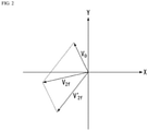
- FIG. 2 is a diagram for describing a process performed in the processor in the first embodiment.
- the graph illustrated in FIG. 2 is a graph wherein a horizontal axis is an X output of the lock-in amplifier 19 and a vertical axis is a Y output thereof. Note that the graph illustrated in FIG. 2 can also be seen as a graph of a complex plane wherein the horizontal axis is a real axis and the vertical axis is an imaginary axis.
- the 2f component is represented as vector V 2f
- the 2f noise component is represented as vector Vo.
- the noise-removed 2f component is represented as vector V' 2f .
- a length of vector V 2f indicates an amplitude R of the 2f component and that a counterclockwise rotation angle of vector V 2f relative to the positive real axis indicates a phase ⁇ of the 2f component.
- a length of vector Vo indicates the amplitude Ro of the 2f noise component, and a counterclockwise rotation angle of vector Vo relative to the positive real axis indicates the phase ⁇ 0 of the 2f component.
- a length of vector V' 2f indicates the amplitude R' 2f of the noise-removed 2f component, and a counterclockwise rotation angle of vector V' 2f relative to the positive real axis indicates a phase of the noise-removed 2f component.
- the 2f component detected by the lock-in amplifier 19 (vector V 2f in FIG. 2 ) is represented as a sum of the noise-removed 2f component (vector V' 2f in FIG. 2 ) and the 2f noise component (vector Vo).
- the noise-removed 2f component (vector V' 2f in FIG. 2 ) is the original 2f component unaffected by the 2f noise component.
- the processor 22 uses formula (4) above to subtract vector Vo from the 2f component detected by the lock-in amplifier 19 (vector V 2f in FIG. 2 ) to calculate a length (amplitude R' 2f of the noise-removed 2f component) of the original 2f component (vector V' 2f in FIG. 2 ).
- the processor 22 measures the concentration of the measurement target gas GS based on a ratio of the amplitude R' 2f of the noise-removed 2f component relative to an amplitude R 1f of the 1f component detected by the lock-in amplifier 19 (R' 2f /R 1f ).
- the concentration of the measurement target gas GS is measured based on the above ratio in order to reduce an effect of fluctuations in a light reception amount of the laser light due to factors other than the measurement target gas.
- the output unit 23 outputs a computation result of the processor 22 to the outside.
- the output unit 23 outputs information indicating the concentration of the measurement target gas GS measured by the processor 22.
- the output unit 23 may output, other than the information indicating the concentration of the measurement target gas GS, information indicating the 2f component, information indicating the 1f component, information indicating the 2f noise component, and other various information.
- the output unit 23 may output to the outside a signal indicating the above information or perform output to the outside by displaying the above information.
- FIG. 3 is a flowchart illustrating a gas analysis method according to the first embodiment. First, prior to measuring the measurement target gas GS, a process of acquiring the amplitude Ro and the phase ⁇ 0 of the 2f noise component is performed.
- a process of emitting the laser light modulated by the modulation frequency f, detecting the laser light reflected by the scatterer SM by the photodetector 17, and detecting the received signal output from the photodetector 17 by the lock-in amplifier 19 is performed in the gas analysis device 10. Then, a process of acquiring an amplitude and a phase of the 2f component detected by the lock-in amplifier 19 (step S11) and storing the acquired amplitude and phase of the 2f component as the amplitude Ro and the phase ⁇ 0 in the storage 21 is performed in the signal processing device 20 (step S12).
- the measurement target gas GS is measured.
- a process of emitting the laser light modulated by the modulation frequency f (first step), obtaining the received signal by detecting the laser light passed through the measurement target gas GS by the photodetector 17 (second step), and detecting the received signal by the lock-in amplifier 19 is performed in the gas analysis device 10.
- a process of acquiring the amplitude R 1f of the 1f component and the amplitude R 2f and phase ⁇ 2f of the 2f component of the measurement target gas detected by the lock-in amplifier 19 is performed in the signal processing device 20 (step S13).
- a process of performing the computation indicated by formula (4) above to calculate the amplitude R' 2f of the noise-removed 2f component is performed in the processor 22 (step S14; third step). For example, a process of calculating the amplitude R' 2f of the noise-removed 2f component by substituting the amplitude Ro and the phase ⁇ 0 stored in the storage 21 at step S12 and the amplitude R 2f and the phase ⁇ 2f of the 2f component acquired at step S13 into formula (4) above is performed in the processor 22.
- step S15 a process of calculating the concentration of the measurement target gas GS by calculating the ratio of the amplitude R' 2f of the noise-removed 2f component relative to the amplitude R 1f of the 1f component obtained at step S13 (R' 2f /R 1f ) is performed in the processor 22 (step S15; fourth step). Then, the information indicating the concentration of the measurement target gas GS measured by the processor 22 is output from the output unit 23. Subsequently, the processes of steps S13 to S15 are repeatedly performed at certain time intervals prescribed in advance.
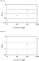
- FIG. 4 is a diagram illustrating a measurement result of the gas analysis system according to the first embodiment.
- the measurement results illustrated in FIG. 4 are results of measuring methane (CH 4 ) gas as the measurement target gas;
- (a) in FIG. 4 is a diagram illustrating the measurement result of the gas analysis system 1 of the present embodiment, and
- (b) in FIG. 4 is a diagram illustrating a measurement result of a conventional gas analysis system.
- the measurement result illustrated in (a) in FIG. 4 indicates a relationship between, on one hand, the amplitude ratio between the noise-removed 2f component and the 1f component (R' 2f /R 1f ) and, on the other, a concentration of the methane gas
- the measurement result illustrated in (b) in FIG. 4 indicates a relationship between, on one hand, an amplitude ratio between the 2f component and the 1f component (R 2f /R 1f ) and, on the other, the concentration of the methane gas.
- the linearity of the graph illustrating the relationship between, on one hand, the amplitude ratio between the noise-removed 2f component and the 1f component (R' 2f /R 1f ) and, on the other, the concentration of the methane gas is maintained even if the concentration is no greater than 100 [ppmm]. It is thereby understood that in the present embodiment, the concentration of the measurement target gas is being able to be precisely measured even if the concentration of the measurement target gas is low.
- the laser light modulated by the predetermined modulation frequency f is emitted, and the received signal is obtained by receiving the laser light passed through the measurement target gas GS.
- the 2f noise component arising on the optical path of the laser light is removed from the 2f component included in the received signal to obtain the noise-removed 2f component.
- the concentration of the measurement target gas GS is found based on a magnitude of the noise-removed 2f component.
- the present embodiment can remove a component having a set phase, such as optical interference noise. This enables precise measurement of the concentration of the measurement target gas GS up to a detection-limit level determined by RIN (relative intensity noise) of the semiconductor laser 13 and white noise of circuits such as the amplifier 18.
- RIN relative intensity noise
- the gas analysis system in the present embodiment has a configuration similar to the gas analysis system 1 illustrated in FIG. 1 .
- the present embodiment and the first embodiment above differ in an acquisition method of the amplitude Ro and the phase ⁇ 0 of the 2f noise component. That is, the present embodiment and the first embodiment differ in processes of steps S11, S12 illustrated in FIG. 3 .
- the amplitude and the phase of the 2f component detected by the lock-in amplifier 19 are acquired at the time when the measurement target gas GS is not present on the optical path of the laser light emitted from the gas analysis device 10. Then, in the process of step S11 illustrated in FIG. 3 , the acquired amplitude and phase of the 2f component are stored in the storage 21 as the amplitude Ro and the phase ⁇ 0 of the 2f noise component.
- the present embodiment acquires an amplitude and a phase of the 2f component detected by the lock-in amplifier 19 at a time when the measurement target gas GS is present on the optical path of the laser light at a known first concentration. It also acquires an amplitude and a phase of the 2f component detected by the lock-in amplifier 19 at a time when the measurement target gas GS is present on the optical path of the laser light at a known second concentration. Then, using the two amplitudes and phases that are acquired and the concentrations of the measurement target gas GS (first concentration, second concentration), the amplitude Ro and the phase ⁇ 0 of the 2f noise component are found by computation.
- two types of gas cells where the measurement target gas GS is enclosed on the optical path of the laser light may be disposed.
- the amplitudes and the phases of the 2f component detected by the lock-in amplifier 19 may be acquired by alternatingly disposing on the optical path of the laser light a gas cell wherein the measurement target gas GS is enclosed at the first concentration above and a gas cell wherein the measurement target gas GS is enclosed at the second concentration above.
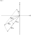
- FIG. 5 is a diagram for describing the method of calculating the 2f noise component in the second embodiment.
- the horizontal axis is the X output of the lock-in amplifier 19, and the vertical axis is the Y output thereof.
- the graph illustrated in FIG. 5 can also be seen as a graph of a complex plane wherein the horizontal axis is a real axis and the vertical axis is an imaginary axis.
- the 2f component detected by the lock-in amplifier 19 at the time when the measurement target gas GS is present on the optical path of the laser light at the known first concentration is represented as vector V1 2f .
- the 2f component detected by the lock-in amplifier 19 at the time when the measurement target gas GS is present on the optical path of the laser light at the known second concentration is represented as vector V2 2f .
- the 2f noise component is represented as vector V 0 .
- vector V1' 2f in FIG. 5 indicates the original 2f component unaffected by the 2f noise component at the time when the measurement target gas GS is present at the first concentration.
- vector V2' 2f indicates the original 2f component unaffected by the 2f noise component at the time when the measurement target gas GS is present at the second concentration.
- a length (amplitude) of vector V1' 2f is a length according to the first concentration of the measurement target gas GS.
- a length (amplitude) of vector V2' 2f is a length according to the second concentration of the measurement target gas GS.
- the first concentration of the measurement target gas GS is referred to as d1
- the second concentration of the measurement target gas GS is referred to as d2.
- the signal processing device 20 calculates the 2f noise component (vector Vo) by performing the computation indicated in formula (5) below.
- V 0 d 2 d 2 ⁇ d 1 V 1 2 f ⁇ d 1 d 2 ⁇ d 1 V 2 2 f
- the length of vector Vo is the amplitude Ro of the 2f noise component
- the counterclockwise rotation angle of vector Vo relative to the positive real axis is the phase ⁇ 0 of the 2f noise component.
- the amplitude Ro and the phase ⁇ 0 of the 2f noise component found in this manner are stored in the storage 21.
- the present embodiment and the first embodiment above only differ in the acquisition method of the amplitude Ro and the phase ⁇ 0 of the 2f noise component.
- the 2f noise component arising on the optical path of the laser light is removed from the 2f component included in the received signal to obtain the noise-removed 2f component, and the concentration of the measurement target gas GS is found based on the magnitude of the noise-removed 2f component. This enables improvement of a detection limit of the concentration of the measurement target gas GS without giving rise to demerits such as increased costs, a complicated configuration, reduced freedom in design, and cumbersome adjustment.
- the gas analysis system in the present embodiment has a configuration similar to the gas analysis system 1 illustrated in FIG. 1 .
- the present embodiment and the first embodiment above differ in an acquisition method of the amplitude Ro and the phase ⁇ 0 of the 2f noise component and a process of calculating the amplitude R' 2f of the noise-removed 2f component performed by the processor 22.
- the present embodiment is for a situation wherein a modulation frequency is high and a measurement distance (optical path length of the laser light) changes variously.
- the phase of the laser light (laser light detected by the photodetector 17) relative to the reference signal RS used in the lock-in amplifier 19 changes.
- the present embodiment enables an improved detection limit of the concentration of the measurement target gas GS by correcting such a phase change.
- the storage 21 stores a phase ⁇ 01f of the 1f component and an amplitude R 02f and phase ⁇ 02f of the 2f noise component from when the optical path length of the laser light is set to a reference length prescribed in advance (for example, 0 [m]).
- the amplitude and the phase of the 2f noise component are written as "amplitude R 02f " and "phase ⁇ 02f " so as to be differentiated from the amplitude Ro and the phase ⁇ 0 of the 2f noise component in the first and second embodiments.
- the phases ⁇ 01f , ⁇ 02f are phases whose basis is the phase of the reference signal RS output from the signal generator 11.
- the processor 22 calculates a phase difference ⁇ between the phase ⁇ 1f of the 1f component obtained when the optical path length of the laser light is not set to the reference length and the phase ⁇ 01f of the 1f component obtained when the optical path length of the laser light is set to the reference length. Moreover, the processor 22 uses the detection result of the gas analysis device 10 (detection result of the lock-in amplifier 19) and the amplitude R 02f and the phase ⁇ 02f of the 2f noise component stored in the storage 21 to calculate the concentration of the measurement target gas GS.
- the processor 22 performs a computation of removing the amplitude R 02f and the phase ⁇ 02f of the 2f noise component stored in the storage 21 from the amplitude R 2f and the phase ⁇ 2f of the 2f component detected by the lock-in amplifier 19. At this time, the processor 22 corrects the phase ⁇ 2f of the 2f component in consideration of the above phase difference ⁇ of the 1f component.
- the processor 22 performs the computation indicated in formula (6) below to calculate the amplitude R' 2f of the noise-removed 2f component.
- R 2 f ⁇ R 2 f cos ⁇ 2 f ⁇ ⁇ ⁇ R 02 f cos ⁇ 02 f 2 + R 2 f sin ⁇ 2 f ⁇ ⁇ ⁇ R 02 f sin ⁇ 02 f 2
- FIG. 6 is a flowchart illustrating the gas analysis method according to the third embodiment.
- a process of acquiring the phase ⁇ 01f of the 1f component and the amplitude R 02f and phase ⁇ 02f of the 2f noise component from when the optical path length of the laser light is set to the reference length is performed prior to measuring the measurement target gas GS.
- a process of acquiring the phase ⁇ 01f of the 1f component and the amplitude R 02f and phase ⁇ 02f of the 2f noise component from when the optical path length of the laser light is set to the reference length is performed prior to measuring the measurement target gas GS.
- a process of acquiring the phase ⁇ 01f of the 1f component and the amplitude R 02f and phase ⁇ 02f of the 2f noise component from when the optical path length of the laser light is set to the reference length is performed prior to measuring the measurement target gas GS.
- a process of storing the acquired phase of the 1f component as the phase ⁇ 01f in the storage 21 and storing the acquired amplitude and phase of the 2f component as the amplitude R 02f and the phase ⁇ 02f in the storage 21 is performed in the signal processing device 20 (step S22).
- the measurement target gas GS is measured. For example, in a state where the above jig is removed from the optical path of the laser light and the measurement target gas GS is present on the optical path of the laser light, a process of emitting the laser light modulated by the modulation frequency f (first step), obtaining the received signal by detecting the laser light passed through the measurement target gas GS by the photodetector 17 (second step), and detecting the received signal by the lock-in amplifier 19 is performed in the gas analysis device 10.
- step S23 a process of acquiring the amplitude R 1f and the phase ⁇ 1f of the 1f component and the amplitude R 2f and the phase ⁇ 2f of the 2f component of the measurement target gas detected by the lock-in amplifier 19 is performed in the signal processing device 20 (step S23).
- step S24 a process of calculating the phase difference ⁇ between the phase ⁇ 1f of the 1f component acquired at step S23 and the phase ⁇ 01f of the 1f component stored in the storage 21 is performed in the processor 22 (step S24).
- step S25 a process of performing the computation indicated by formula (6) above to calculate the amplitude R' 2f of the noise-removed 2f component in consideration of the phase difference ⁇ of the 1f component is performed in the processor 22 (step S25; third step).
- a process of calculating the amplitude R' 2f of the noise-removed 2f component by substituting the amplitude R 02f and the phase ⁇ 02f stored in the storage 21 at step S22, the amplitude R 2f and the phase ⁇ 2f of the 2f component acquired at step S23, and the phase difference ⁇ calculated at step S14 into formula (6) above is performed in the processor 22.
- step S26 a process of calculating the concentration of the measurement target gas GS by calculating the ratio of the amplitude R' 2f of the noise-removed 2f component relative to the amplitude R 1f of the 1f component obtained at step S23 (R' 2f /R 1f ) is performed in the processor 22 (step S26; fourth step). Then, the information indicating the concentration of the measurement target gas GS measured by the processor 22 is output from the output unit 23. Subsequently, the processes of steps S23 to S26 are repeatedly performed at certain time intervals prescribed in advance.
- the present embodiment and the first embodiment above only differ in the acquisition method of the amplitude R 02f and the phase ⁇ 02f of the 2f noise component and the process of calculating the amplitude R' 2f of the noise-removed 2f component performed by the processor 22.
- the 2f noise component arising on the optical path of the laser light is removed from the 2f component included in the received signal to obtain the noise-removed 2f component, and the concentration of the measurement target gas GS is found based on the magnitude of the noise-removed 2f component. This enables improvement of a detection limit of the concentration of the measurement target gas GS without giving rise to demerits such as increased costs, a complicated configuration, reduced freedom in design, and cumbersome adjustment.
- the present embodiment calculates the phase difference ⁇ between the phase ⁇ 1f of the 1f component obtained when the optical path length of the laser light is not set to the reference length and the phase ⁇ 01f of the 1f component obtained when the optical path length of the laser light is set to the reference length and corrects the phase ⁇ 2f of the 2f component. This enables improvement of the detection limit of the concentration of the measurement target gas GS even when the modulation frequency is high and the measurement distance (optical path length of the laser light) changes variously.
- the present invention is not limited to the above embodiments and can be freely modified within the scope of the present invention.
- the above embodiments describe a situation of measuring the concentration of the measurement target gas GS based on the second-order harmonic component (2f component) of the modulation frequency f of the laser light.
- the concentration of the measurement target gas GS may be measured based on an nth-order harmonic component (n being an integer no less than 3) of the modulation frequency f of the laser light.
- the above embodiments describe an example of detecting the 1f component and the 2f component included in the received signal output from the photodetector 17 by the lock-in amplifier 19.
- the lock-in amplifier 19 may be omitted, and the signal processing device 20 may be equipped with the functions of the lock-in amplifier 19 so a signal processing unit detects the 1f component and the 2f component included in the received signal.
- the signal processing device 20 may be equipped with an FFT (fast Fourier transform) function instead of the functions of the lock-in amplifier 19 so a signal processing unit detects the 1f component and the 2f component included in the received signal.
- FFT fast Fourier transform
- the functions of the signal processing device 20 provided in the gas analysis systems of the above embodiments may be realized as software by installing a program that realizes these functions on a computer. That is, the functions of the signal processing device 20 may be realized by cooperation between software and hardware resources. Note that the functions of the signal processing device 20 may be realized using hardware such as an FPGA(fieldprogrammable gate array), LSI(large-scale integration), or an ASIC(application-specific integrated circuit).
Landscapes
- Physics & Mathematics (AREA)
- Spectroscopy & Molecular Physics (AREA)
- General Physics & Mathematics (AREA)
- Biochemistry (AREA)
- Chemical & Material Sciences (AREA)
- Analytical Chemistry (AREA)
- Life Sciences & Earth Sciences (AREA)
- General Health & Medical Sciences (AREA)
- Health & Medical Sciences (AREA)
- Immunology (AREA)
- Pathology (AREA)
- Optics & Photonics (AREA)
- Investigating Or Analysing Materials By Optical Means (AREA)
Abstract
Description
- The present invention generally relates to a gas analysis system and a gas analysis method.
- Among gas analysis systems that analyze a measurement target gas, there is one that measures a concentration of a measurement target gas based on an absorbance of light irradiated to the measurement target gas. In such a gas analysis system, to increase measurement precision (sensitivity), wavelength-modulation spectroscopy is sometimes used. Wavelength-modulation spectroscopy is a technique of irradiating a laser light modulated by a modulation frequency f to a measurement target gas and measuring a concentration of the measurement target gas based on a second-order harmonic component (2f component) obtained by detecting the laser light upon its transmission through the measurement target gas.
- In wavelength-modulation spectroscopy, the concentration of the measurement target gas is often measured upon calculating a ratio of the 2f component to a component (1f component) of the modulation frequency f that is detected and standardizing a light reception amount. This is to reduce an effect of fluctuations in the light reception amount of the laser light due to factors other than the measurement target gas. Note that wavelength-modulation spectroscopy is also sometimes referred to as 2f detection.
Patent literature 1 below discloses one example of a conventional gas analysis system that uses wavelength-modulation spectroscopy to measure a gas concentration. - Patent Literature 1:
WO 2017/014097 A1 - Now, in the above gas analysis system, optical interference noise may be generated when the laser light passes through a lens or other optical element, a window, a thin film, or the like. This optical interference noise arises due to, for example, interference caused by the laser light upon undergoing multiple reflection inside an optical element or the like, and a magnitude thereof changes periodically depending on a wavelength of the laser light. For example, just as a transmittance of a Fabry-Pérot etalon becomes periodic relative to wavelength, the magnitude of the optical interference noise also becomes periodic relative to the wavelength. When there is such optical interference noise, there is a problem of a worsened detection limit of the concentration of the measurement target gas.
- One or more embodiments provide a gas analysis system and a gas analysis method that can improve a detection limit of a concentration of a measurement target gas.
- According to one or more embodiments, a gas analysis system (1) includes: a light-emitting element (13) that emits a laser light modulated by a predetermined modulation frequency (f); a light-receiving element (17) that receives the laser light upon the laser light passing through a measurement target gas (GS); and a signal processing device (20) that calculates a concentration of the measurement target gas based on a magnitude of a third component obtained by removing, from a first component that is a component having an N-frequency, meaning a frequency n times (n being an integer no less than 2) the modulation frequency included in a received signal output from the light-receiving element, a second component that is a component, of the same frequency as the first component, of optical interference noise arising on an optical path of the laser light from the light-emitting element to the light-receiving element.
- Furthermore, the gas analysis system according to one or more embodiments is provided with a detector (19) that detects an amplitude (R2f) and a phase (θ2f) of the first component included in the received signal, and the signal processing device is provided with a storage (21) that stores an amplitude (R0, R02f) and a phase (θ0, θ02f) of the second component and a processor that calculates the third component by using the amplitude and the phase of the first component detected by the detector and the amplitude and the phase of the second component stored in the storage to perform a computation of removing the second component from the first component.
- Furthermore, in the gas analysis system according to one or more embodiments, the detector detects, in addition to the first component, a fundamental component that is a component having the same frequency as the modulation frequency included in the received signal, and the processor calculates the concentration of the measurement target gas based on a ratio (R'2f/R1f) of an amplitude (R'2f) of the third component to an amplitude (Rif) of the fundamental component.
- Furthermore, in the gas analysis system according to one or more embodiments, the amplitude and the phase of the second component stored in the storage are an amplitude and a phase of the first component detected by the detector at a time when the measurement target gas is not present on the optical path of the laser light or a state where the concentration of the measurement target gas on the optical path of the laser light is sufficiently low, for example lower than a predetermined value.
- Alternatively, in the gas analysis system according to one or more embodiments, the amplitude and the phase of the second component stored in the storage are an amplitude and a phase obtained by performing a predetermined computation using an amplitude and a phase of the first component detected by the detector at a time when the measurement target gas is present on the optical path of the laser light at a known first concentration and an amplitude and a phase of the first component detected by the detector at a time when the measurement target gas is present on the optical path of the laser light at a known second concentration.
- Alternatively, in the gas analysis system according to one or more embodiments, the amplitude and the phase of the second component stored in the storage are an amplitude and a phase of the first component detected by the detector at a time when an optical path length of the laser light is set to a reference length prescribed in advance, and the processor calculates the third component by performing a computation of removing the second component from the first component upon correcting, based on a difference between a phase of the fundamental component detected by the detector at a time when the optical path length of the laser light is not set to the reference length and a phase of the fundamental component detected by the detector at the time when the optical path length of the laser light is set to the reference length, a phase of the first component detected by the detector at the time when the optical path length of the laser light is not set to the reference length.
- A gas analysis method according to one or more embodiments has: a first step of emitting a laser light modulated by a predetermined modulation frequency (f); a second step of obtaining a received signal by receiving the laser light upon the laser light passing through a measurement target gas (GS); a third step (S14, S25) of obtaining a third component by removing, from a first component that is a component having an N-frequency that is n times (n being an integer no less than 2) the modulation frequency included in the received signal, a second component that is a component, of the same frequency as the first component, of optical interference noise arising on an optical path of the laser light; and a fourth step (S15, S26) of calculating a concentration of the measurement target gas based on a magnitude of the third component.
- Furthermore, the gas analysis method according to one or more embodiments further includes: a step (S11, S12, S21, S22) of calculating the second component in advance, prior to measuring the measurement target gas.
- Further embodiments are defined in the dependent claims. One or more embodiments can improve a detection limit of a concentration of a measurement target gas.
-
-
FIG. 1 is a block diagram illustrating a configuration of main parts of a gas analysis system according to a first embodiment. -
FIG. 2 is a diagram for describing a process performed in a processor of a gas analysis system according to the first embodiment. -
FIG. 3 is a flowchart illustrating a gas analysis method according to the first embodiment. -
FIGS. 4A and 4B are diagrams illustrating measurement results of the gas analysis system according to the first embodiment. -
FIG. 5 is a diagram for describing a method of calculating a 2f noise component according to a second embodiment. -
FIG. 6 is a flowchart illustrating a gas analysis method according to a third embodiment. - Gas analysis systems and gas analysis methods according to one or more embodiments of the present invention are described in detail below with reference to the drawings. In the following, first, an overview of the present embodiments is described. Afterward, details of each embodiment are described.
- One or more embodiments enable an improvement of a detection limit of a concentration of a measurement target gas. For example, they enable high-precision measurement of a concentration of a measurement target gas even when the concentration of the measurement target gas is low. That is, they enable high-precision measurement of the concentration of the measurement target gas even near a detection limit that is found theoretically.
- In wavelength-modulation spectroscopy, a magnitude of an amplitude of a second-order harmonic component (2f component) that is detected is represented by formula (1) below.
[Math. 1]
- In formula (1) above, Is is the magnitude (RMS: root mean square) of the amplitude of the 2f component. Moreover, s is a coefficient indicating a sensitivity of a light-receiving element, Pdc is a received power of a laser light, and k2 is a constant determined by a modulation frequency of the laser light. Moreover, α0 is an absorbance at a center wavelength of a measurement target gas, and CR is a gas concentration of the measurement target gas.
- Furthermore, noise IN of the 2f component that is detected is represented by formula (2) below.
[Math. 2]
- In formula (2) above, RIN is relative intensity noise of a laser light source, and Idark is a dark current of the light-receiving element. Moreover, e is the elementary charge, kB is the Boltzmann constant, T is a temperature of the light-receiving element, Rsh is a shunt resistance of the light-receiving element, and Δt is a time constant of a lock-in amplifier used to detect the 2f component.
- A detection limit CR limit of the concentration of the measurement target gas when a signalto-noise ratio (SN ratio: signal-noise ratio) is "1" is indicated by formula (3) below.
[Math. 2]
- Here, in formula (2) above indicating the noise IN of the 2f component and formula (3) above indicating the detection limit CR limit of the concentration of the measurement target gas, optical interference noise is not taken into consideration. Optical interference noise is generated when the laser light passes through a lens or other optical element, a window, a thin film, or the like. For example, optical interference noise arises due to interference caused by the laser light upon undergoing multiple reflection inside an optical element or the like, and a magnitude thereof changes periodically depending on a wavelength of the laser light or a thickness of the optical element or the like. As such, for example, when a full width at half maximum of the optical interference noise and a full width at half maximum of an absorption spectrum of the measurement target gas are at the same level due to the thickness of the optical element or the like, it is difficult to separate the optical interference noise and the absorption spectrum of the measurement target gas.
- Such optical interference noise can be removed (or reduced) by, for example, applying the following measures (optical measures).
- Forming an antireflective film (AR film) on an incidence face and an emission face of the optical element or the like that is the cause
- Inclining the incidence face and the emission face of the optical element or the like that is the cause relative to an optical path of the laser light
- Designing the FWHM (full width at half maximum) of the absorption spectrum and a period of optical interference to not be the same level
- In one or more embodiments, first, a laser light modulated by a predetermined modulation frequency is emitted, and a received signal is obtained by receiving the laser light upon its passing through a measurement target gas. Next, from a first component, which is a component having an N-frequency that is n times (n being an integer no less than 2) the modulation frequency included in the received signal, a second component, which is a component of the same frequency as the first component of optical interference noise arising on an optical path of the laser light, is removed to obtain a third component. Then, a concentration of the measurement target gas is found based on a magnitude of the third component. This enables improvement of a detection limit of the concentration of the measurement target gas without giving rise to demerits such as increased costs, a complicated configuration, reduced freedom in design, and cumbersome adjustment.
-
FIG. 1 is a block diagram illustrating a configuration of main parts of a gas analysis system according to a first embodiment. As illustrated inFIG. 1 , agas analysis system 1 of the present embodiment is provided with agas analysis device 10 and asignal processing device 20, which is referred to as a processing unit, and uses wavelength-modulation spectroscopy to measure a concentration of a measurement target gas GS. For example, thegas analysis system 1 of the present embodiment irradiates a laser light modulated by a modulation frequency f to the measurement target gas GS and measures the concentration of the measurement target gas GS based on a second-order harmonic component (2f component) that is detected. - The
gas analysis device 10 is provided with asignal generator 11, adrive circuit 12, a semiconductor laser 13 (light-emitting element), anoptical amplifier 14, alens 15, alens 16, a photodetector 17 (light-receiving element), anamplifier 18, and a lock-in amplifier 19 (detector). Such agas analysis device 10 performs emission of the laser light irradiated to the measurement target gas GS, reception of the laser light via the measurement target gas GS, detection of a component of the modulation frequency f (1f component) and the 2f component included in a received signal, and the like. - As controlled by the
signal processing device 20, thesignal generator 11 outputs a control signal CS for controlling thedrive circuit 12 and a reference signal RS used in the lock-inamplifier 19. The reference signal RS output from thesignal generator 11 is synchronized with the control signal CS output from thesignal generator 11. As thissignal generator 11, for example, an arbitrary waveform generator or a function generator can be used. - Based on the control signal CS output from the
signal generator 11, thedrive circuit 12 outputs a drive signal for driving thesemiconductor laser 13. The drive signal output from thedrive circuit 12 is, for example, a signal wherein an alternating current of the modulation frequency f is superimposed on a direct current having a certain magnitude (amplitude). Note that the alternating current of the modulation frequency f may be, for example, sinusoidal or non-sinusoidal. - The
semiconductor laser 13 is driven by the drive signal output from thedrive circuit 12 and emits the laser light irradiated to the measurement target gas GS. The laser light emitted from thesemiconductor laser 13 is, for example, a laser light wherein a center wavelength of modulation is a center wavelength of an absorption spectrum of the measurement target gas GS and a wavelength modulation width (modulation frequency f) is 2.2 times a FWHM of the absorption spectrum of the measurement target gas GS. The wavelength modulation width (modulation frequency f) of the laser light emitted from thesemiconductor laser 13 may be no less than 1 time, no less than 2 times, or no less than 10 times the FWHM of the absorption spectrum of the measurement target gas GS. Note that as thesemiconductor laser 13, for example, a QCL (quantum cascade laser) or an ICL (interband cascade laser) can be used. - The
optical amplifier 14 amplifies the laser light emitted from thesemiconductor laser 13. As thisoptical amplifier 14, for example, an optical fiber amplifier or a semiconductor optical amplifier can be used. Thelens 15 converts the laser light passed through theoptical amplifier 14 into parallel light. As such alens 15, a collimating lens can be used. Note that another optical element (for example, a parabolic mirror) can also be used instead of thelens 15 as long as it can convert the laser light passed through theoptical amplifier 14 into parallel light. - The laser light collimated by the
lens 15 is irradiated to the measurement target gas GS. Of the laser light irradiated to the measurement target gas GS, a portion that is transmitted through the measurement target gas GS is reflected by a scatterer SM such as a wall. Afterward, it is again transmitted through the measurement target gas GS and becomes incident on thelens 16. Note that a distance between thegas analysis device 10 and the scatterer SM may be any distance but is set to, for example, no greater than about 100 [m]. - The
lens 16 condenses the laser light passed through the measurement target gas GS onto thephotodetector 17. As such alens 16, a condensing lens can be used. Note that another optical element (for example, a parabolic mirror) can also be used instead of thelens 16 as long as it can condense the laser light passed through the measurement target gas GS onto thephotodetector 17. Thephotodetector 17 converts the laser light condensed by thelens 16 into an electrical signal and outputs this as the received signal. As thisphotodetector 17, for example, a PD (photodiode) can be used. - The
amplifier 18 amplifies the received signal output from thephotodetector 17. An amplification rate of theamplifier 18 is set to an appropriate amplification rate in response to, for example, an intensity of the laser light incident on thephotodetector 17. When thephotodetector 17 is a PD, as theamplifier 18, an IV conversion circuit that converts a photocurrent output as the received signal from thephotodetector 17 into a voltage can be used. - The lock-in
amplifier 19 uses the reference signal RS output from thesignal generator 11 to detect a specific frequency component from the received signal amplified by theamplifier 18. For example, the lock-inamplifier 19 uses the reference signal RS output from thesignal generator 11 to perform phase-sensitive detection and detects the 1f component (fundamental component) and the 2f component (first component) from the received signal amplified by theamplifier 18. - The
signal processing device 20 is provided with astorage 21, aprocessor 22, and anoutput unit 23. It controls operations of thegas analysis device 10 and uses a detection result of the gas analysis device 10 (detection result of the lock-in amplifier 19) to measure the concentration of the measurement target gas GS. Thesignal processing device 20 is realized by, for example, a computer such as a personal computer. - The
storage 21 stores a predetermined component (second component) of optical interference noise arising on an optical path of the laser light from thesemiconductor laser 13 to thephotodetector 17. For example, thestorage 21 stores an amplitude Ro and a phase θ0 of a component, among components of the optical interference noise, of the same frequency as the 2f component (referred to as a "2f noise component" hereinbelow). Note that the phase θ0 is a phase whose basis is a phase of the reference signal RS output from thesignal generator 11. Here, the amplitude Ro and the phase θ0 stored in thestorage 21 is, for example, an amplitude and a phase of the 2f component detected by the lock-inamplifier 19 at a time when the measurement target gas GS is not present on the optical path of the laser light emitted from the gas analysis device 10 (or a concentration of the measurement target gas GS on the optical path of the laser light is sufficiently low). Here, "a concentration of the measurement target gas GS [being] sufficiently low" refers to a concentration of the measurement target gas GS on the optical path of the laser light being sufficiently lower than a concentration of the measurement target gas GS on the optical path of the laser light at a time of concentration measurement; this concentration may be lower than a detection limit of thegas analysis system 1. - The
processor 22 uses the detection result of the gas analysis device 10 (detection result of the lock-in amplifier 19) and the amplitude Ro and the phase θ0 of the 2f noise component stored in thestorage 21 to calculate the concentration of the measurement target gas GS. For example, theprocessor 22 performs a computation of removing the amplitude Ro and the phase θ0 of the 2f noise component stored in thestorage 21 from an amplitude R2f and a phase θ2f of the 2f component detected by the lock-inamplifier 19. Theprocessor 22 thereby calculates an amplitude R'2f of a component wherein the 2f noise component is removed from the 2f component (referred to as a "noise-removed 2f component" hereinbelow; third component). - For example, the
processor 22 performs the computation indicated in formula (4) below to calculate the amplitude R'2f of the noise-removed 2f component.
[Math. 4]
-
FIG. 2 is a diagram for describing a process performed in the processor in the first embodiment. The graph illustrated inFIG. 2 is a graph wherein a horizontal axis is an X output of the lock-inamplifier 19 and a vertical axis is a Y output thereof. Note that the graph illustrated inFIG. 2 can also be seen as a graph of a complex plane wherein the horizontal axis is a real axis and the vertical axis is an imaginary axis. InFIG. 2 , the 2f component is represented as vector V2f, and the 2f noise component is represented as vector Vo. Moreover, the noise-removed 2f component is represented as vector V'2f. - Note that a length of vector V2f indicates an amplitude R of the 2f component and that a counterclockwise rotation angle of vector V2f relative to the positive real axis indicates a phase θ of the 2f component. Moreover, a length of vector Vo indicates the amplitude Ro of the 2f noise component, and a counterclockwise rotation angle of vector Vo relative to the positive real axis indicates the phase θ0 of the 2f component. Likewise, a length of vector V'2f indicates the amplitude R'2f of the noise-removed 2f component, and a counterclockwise rotation angle of vector V'2f relative to the positive real axis indicates a phase of the noise-removed 2f component.
- As illustrated in
FIG. 2 , the 2f component detected by the lock-in amplifier 19 (vector V2f inFIG. 2 ) is represented as a sum of the noise-removed 2f component (vector V'2f inFIG. 2 ) and the 2f noise component (vector Vo). Note that the noise-removed 2f component (vector V'2f inFIG. 2 ) is the original 2f component unaffected by the 2f noise component. Theprocessor 22 uses formula (4) above to subtract vector Vo from the 2f component detected by the lock-in amplifier 19 (vector V2f inFIG. 2 ) to calculate a length (amplitude R'2f of the noise-removed 2f component) of the original 2f component (vector V'2f inFIG. 2 ). - Furthermore, the
processor 22 measures the concentration of the measurement target gas GS based on a ratio of the amplitude R'2f of the noise-removed 2f component relative to an amplitude R1f of the 1f component detected by the lock-in amplifier 19 (R'2f/R1f). Here, the concentration of the measurement target gas GS is measured based on the above ratio in order to reduce an effect of fluctuations in a light reception amount of the laser light due to factors other than the measurement target gas. - The
output unit 23 outputs a computation result of theprocessor 22 to the outside. For example, theoutput unit 23 outputs information indicating the concentration of the measurement target gas GS measured by theprocessor 22. Note that theoutput unit 23 may output, other than the information indicating the concentration of the measurement target gas GS, information indicating the 2f component, information indicating the 1f component, information indicating the 2f noise component, and other various information. Theoutput unit 23 may output to the outside a signal indicating the above information or perform output to the outside by displaying the above information. -
FIG. 3 is a flowchart illustrating a gas analysis method according to the first embodiment. First, prior to measuring the measurement target gas GS, a process of acquiring the amplitude Ro and the phase θ0 of the 2f noise component is performed. - For example, at the time when the measurement target gas GS is not present, a process of emitting the laser light modulated by the modulation frequency f, detecting the laser light reflected by the scatterer SM by the
photodetector 17, and detecting the received signal output from thephotodetector 17 by the lock-inamplifier 19 is performed in thegas analysis device 10. Then, a process of acquiring an amplitude and a phase of the 2f component detected by the lock-in amplifier 19 (step S11) and storing the acquired amplitude and phase of the 2f component as the amplitude Ro and the phase θ0 in thestorage 21 is performed in the signal processing device 20 (step S12). - Next, the measurement target gas GS is measured. For example, in a state where the measurement target gas GS is present, a process of emitting the laser light modulated by the modulation frequency f (first step), obtaining the received signal by detecting the laser light passed through the measurement target gas GS by the photodetector 17 (second step), and detecting the received signal by the lock-in
amplifier 19 is performed in thegas analysis device 10. Then, a process of acquiring the amplitude R1f of the 1f component and the amplitude R2f and phase θ2f of the 2f component of the measurement target gas detected by the lock-inamplifier 19 is performed in the signal processing device 20 (step S13). - Next, a process of performing the computation indicated by formula (4) above to calculate the amplitude R'2f of the noise-removed 2f component is performed in the processor 22 (step S14; third step). For example, a process of calculating the amplitude R'2f of the noise-removed 2f component by substituting the amplitude Ro and the phase θ0 stored in the
storage 21 at step S12 and the amplitude R2f and the phase θ2f of the 2f component acquired at step S13 into formula (4) above is performed in theprocessor 22. - Next, a process of calculating the concentration of the measurement target gas GS by calculating the ratio of the amplitude R'2f of the noise-removed 2f component relative to the amplitude R1f of the 1f component obtained at step S13 (R'2f/R1f) is performed in the processor 22 (step S15; fourth step). Then, the information indicating the concentration of the measurement target gas GS measured by the
processor 22 is output from theoutput unit 23. Subsequently, the processes of steps S13 to S15 are repeatedly performed at certain time intervals prescribed in advance. -
FIG. 4 is a diagram illustrating a measurement result of the gas analysis system according to the first embodiment. The measurement results illustrated inFIG. 4 are results of measuring methane (CH4) gas as the measurement target gas; (a) inFIG. 4 is a diagram illustrating the measurement result of thegas analysis system 1 of the present embodiment, and (b) inFIG. 4 is a diagram illustrating a measurement result of a conventional gas analysis system. Note that the measurement result illustrated in (a) inFIG. 4 indicates a relationship between, on one hand, the amplitude ratio between the noise-removed 2f component and the 1f component (R'2f/R1f) and, on the other, a concentration of the methane gas, and the measurement result illustrated in (b) inFIG. 4 indicates a relationship between, on one hand, an amplitude ratio between the 2f component and the 1f component (R2f/R1f) and, on the other, the concentration of the methane gas. - Referring to the measurement result illustrated in (b) in
FIG. 4 , when the concentration is no greater than 100 [ppmm], the linearity of the graph illustrating the relationship between, on one hand, the amplitude ratio between the 2f component and the 1f component (R2f/R1f) and, on the other, the concentration of the methane gas is disrupted. It is thereby understood that conventionally, the concentration of the measurement target gas is not being able to be precisely measured when the concentration is no greater than 100 [ppmm]. In contrast, referring to the measurement result illustrated in (a) inFIG. 4 , the linearity of the graph illustrating the relationship between, on one hand, the amplitude ratio between the noise-removed 2f component and the 1f component (R'2f/R1f) and, on the other, the concentration of the methane gas is maintained even if the concentration is no greater than 100 [ppmm]. It is thereby understood that in the present embodiment, the concentration of the measurement target gas is being able to be precisely measured even if the concentration of the measurement target gas is low. - As above, in the present embodiment, first, the laser light modulated by the predetermined modulation frequency f is emitted, and the received signal is obtained by receiving the laser light passed through the measurement target gas GS. Next, the 2f noise component arising on the optical path of the laser light is removed from the 2f component included in the received signal to obtain the noise-removed 2f component. Then, the concentration of the measurement target gas GS is found based on a magnitude of the noise-removed 2f component. This enables improvement of a detection limit of the concentration of the measurement target gas GS without giving rise to demerits such as increased costs, a complicated configuration, reduced freedom in design, and cumbersome adjustment.
- In this manner, by using not only amplitude information but also phase information, the present embodiment can remove a component having a set phase, such as optical interference noise. This enables precise measurement of the concentration of the measurement target gas GS up to a detection-limit level determined by RIN (relative intensity noise) of the
semiconductor laser 13 and white noise of circuits such as theamplifier 18. - Next, a second embodiment is described. The gas analysis system in the present embodiment has a configuration similar to the
gas analysis system 1 illustrated inFIG. 1 . The present embodiment and the first embodiment above differ in an acquisition method of the amplitude Ro and the phase θ0 of the 2f noise component. That is, the present embodiment and the first embodiment differ in processes of steps S11, S12 illustrated inFIG. 3 . - In the first embodiment above, in the process of step S11 illustrated in
FIG. 3 , the amplitude and the phase of the 2f component detected by the lock-inamplifier 19 are acquired at the time when the measurement target gas GS is not present on the optical path of the laser light emitted from thegas analysis device 10. Then, in the process of step S11 illustrated inFIG. 3 , the acquired amplitude and phase of the 2f component are stored in thestorage 21 as the amplitude Ro and the phase θ0 of the 2f noise component. - In contrast, the present embodiment acquires an amplitude and a phase of the 2f component detected by the lock-in
amplifier 19 at a time when the measurement target gas GS is present on the optical path of the laser light at a known first concentration. It also acquires an amplitude and a phase of the 2f component detected by the lock-inamplifier 19 at a time when the measurement target gas GS is present on the optical path of the laser light at a known second concentration. Then, using the two amplitudes and phases that are acquired and the concentrations of the measurement target gas GS (first concentration, second concentration), the amplitude Ro and the phase θ0 of the 2f noise component are found by computation. - When calculating the amplitude R0 and the phase θ0 of the 2f noise component, two types of gas cells where the measurement target gas GS is enclosed on the optical path of the laser light may be disposed. For example, the amplitudes and the phases of the 2f component detected by the lock-in
amplifier 19 may be acquired by alternatingly disposing on the optical path of the laser light a gas cell wherein the measurement target gas GS is enclosed at the first concentration above and a gas cell wherein the measurement target gas GS is enclosed at the second concentration above. -
FIG. 5 is a diagram for describing the method of calculating the 2f noise component in the second embodiment. Note that inFIG. 5 , likeFIG. 2 , the horizontal axis is the X output of the lock-inamplifier 19, and the vertical axis is the Y output thereof. Note that likeFIG. 2 , the graph illustrated inFIG. 5 can also be seen as a graph of a complex plane wherein the horizontal axis is a real axis and the vertical axis is an imaginary axis. - In
FIG. 5 , the 2f component detected by the lock-inamplifier 19 at the time when the measurement target gas GS is present on the optical path of the laser light at the known first concentration is represented as vector V12f. Moreover, the 2f component detected by the lock-inamplifier 19 at the time when the measurement target gas GS is present on the optical path of the laser light at the known second concentration is represented as vector V22f. Moreover, the 2f noise component is represented as vector V0. - Note that vector V1'2f in
FIG. 5 indicates the original 2f component unaffected by the 2f noise component at the time when the measurement target gas GS is present at the first concentration. Moreover, vector V2'2f indicates the original 2f component unaffected by the 2f noise component at the time when the measurement target gas GS is present at the second concentration. A length (amplitude) of vector V1'2f is a length according to the first concentration of the measurement target gas GS. Likewise, a length (amplitude) of vector V2'2f is a length according to the second concentration of the measurement target gas GS. The first concentration of the measurement target gas GS is referred to as d1, and the second concentration of the measurement target gas GS is referred to as d2. - The
signal processing device 20 calculates the 2f noise component (vector Vo) by performing the computation indicated in formula (5) below.
[Math. 5]
- Note that the length of vector Vo is the amplitude Ro of the 2f noise component, and the counterclockwise rotation angle of vector Vo relative to the positive real axis is the phase θ0 of the 2f noise component. The amplitude Ro and the phase θ0 of the 2f noise component found in this manner are stored in the
storage 21. - As above, the present embodiment and the first embodiment above only differ in the acquisition method of the amplitude Ro and the phase θ0 of the 2f noise component. In the present embodiment as well, like the first embodiment, the 2f noise component arising on the optical path of the laser light is removed from the 2f component included in the received signal to obtain the noise-removed 2f component, and the concentration of the measurement target gas GS is found based on the magnitude of the noise-removed 2f component. This enables improvement of a detection limit of the concentration of the measurement target gas GS without giving rise to demerits such as increased costs, a complicated configuration, reduced freedom in design, and cumbersome adjustment.
- Next, a third embodiment is described. The gas analysis system in the present embodiment has a configuration similar to the
gas analysis system 1 illustrated inFIG. 1 . The present embodiment and the first embodiment above differ in an acquisition method of the amplitude Ro and the phase θ0 of the 2f noise component and a process of calculating the amplitude R'2f of the noise-removed 2f component performed by theprocessor 22. The present embodiment is for a situation wherein a modulation frequency is high and a measurement distance (optical path length of the laser light) changes variously. - When the modulation frequency is high and the measurement distance (optical path length of the laser light) changes variously, the phase of the laser light (laser light detected by the photodetector 17) relative to the reference signal RS used in the lock-in
amplifier 19 changes. The present embodiment enables an improved detection limit of the concentration of the measurement target gas GS by correcting such a phase change. - In the present embodiment, the
storage 21 stores a phase θ01f of the 1f component and an amplitude R02f and phase θ02f of the 2f noise component from when the optical path length of the laser light is set to a reference length prescribed in advance (for example, 0 [m]). Note that in the present embodiment, the amplitude and the phase of the 2f noise component are written as "amplitude R02f" and "phase θ02f" so as to be differentiated from the amplitude Ro and the phase θ0 of the 2f noise component in the first and second embodiments. The phases θ01f, θ02f are phases whose basis is the phase of the reference signal RS output from thesignal generator 11. - In the present embodiment, the
processor 22 calculates a phase difference ϕ between the phase θ1f of the 1f component obtained when the optical path length of the laser light is not set to the reference length and the phase θ01f of the 1f component obtained when the optical path length of the laser light is set to the reference length. Moreover, theprocessor 22 uses the detection result of the gas analysis device 10 (detection result of the lock-in amplifier 19) and the amplitude R02f and the phase θ02f of the 2f noise component stored in thestorage 21 to calculate the concentration of the measurement target gas GS. - For example, the
processor 22 performs a computation of removing the amplitude R02f and the phase θ02f of the 2f noise component stored in thestorage 21 from the amplitude R2f and the phase θ2f of the 2f component detected by the lock-inamplifier 19. At this time, theprocessor 22 corrects the phase θ2f of the 2f component in consideration of the above phase difference ϕ of the 1f component. - For example, the
processor 22 performs the computation indicated in formula (6) below to calculate the amplitude R'2f of the noise-removed 2f component.
[Math. 6]
-
FIG. 6 is a flowchart illustrating the gas analysis method according to the third embodiment. First, prior to measuring the measurement target gas GS, a process of acquiring the phase θ01f of the 1f component and the amplitude R02f and phase θ02f of the 2f noise component from when the optical path length of the laser light is set to the reference length is performed. Note that as a method of setting the optical path length of the laser light to the reference length, for example, a method of disposing a jig on the optical path of the laser light can be mentioned. - A process of emitting the laser light modulated by the modulation frequency f in a state where the optical path length of the laser light is set to the reference length; detecting the laser light, upon its being reflected by, for example, the jig, by the
photodetector 17; and detecting the received signal output from thephotodetector 17 by the lock-inamplifier 19 is performed in thegas analysis device 10. Then, a process of acquiring a phase of the 1f component and an amplitude and phase of the 2f component detected by the lock-inamplifier 19 is performed in the signal processing device 20 (step S21). Moreover, a process of storing the acquired phase of the 1f component as the phase θ01f in thestorage 21 and storing the acquired amplitude and phase of the 2f component as the amplitude R02f and the phase θ02f in thestorage 21 is performed in the signal processing device 20 (step S22). - Next, the measurement target gas GS is measured. For example, in a state where the above jig is removed from the optical path of the laser light and the measurement target gas GS is present on the optical path of the laser light, a process of emitting the laser light modulated by the modulation frequency f (first step), obtaining the received signal by detecting the laser light passed through the measurement target gas GS by the photodetector 17 (second step), and detecting the received signal by the lock-in
amplifier 19 is performed in thegas analysis device 10. Then, a process of acquiring the amplitude R1f and the phase θ1f of the 1f component and the amplitude R2f and the phase θ2f of the 2f component of the measurement target gas detected by the lock-inamplifier 19 is performed in the signal processing device 20 (step S23). - Next, a process of calculating the phase difference ϕ between the phase θ1f of the 1f component acquired at step S23 and the phase θ01f of the 1f component stored in the
storage 21 is performed in the processor 22 (step S24). Next, a process of performing the computation indicated by formula (6) above to calculate the amplitude R'2f of the noise-removed 2f component in consideration of the phase difference ϕ of the 1f component is performed in the processor 22 (step S25; third step). For example, a process of calculating the amplitude R'2f of the noise-removed 2f component by substituting the amplitude R02f and the phase θ02f stored in thestorage 21 at step S22, the amplitude R2f and the phase θ2f of the 2f component acquired at step S23, and the phase difference ϕ calculated at step S14 into formula (6) above is performed in theprocessor 22. - Next, a process of calculating the concentration of the measurement target gas GS by calculating the ratio of the amplitude R'2f of the noise-removed 2f component relative to the amplitude R1f of the 1f component obtained at step S23 (R'2f/R1f) is performed in the processor 22 (step S26; fourth step). Then, the information indicating the concentration of the measurement target gas GS measured by the
processor 22 is output from theoutput unit 23. Subsequently, the processes of steps S23 to S26 are repeatedly performed at certain time intervals prescribed in advance. - As above, the present embodiment and the first embodiment above only differ in the acquisition method of the amplitude R02f and the phase θ02f of the 2f noise component and the process of calculating the amplitude R'2f of the noise-removed 2f component performed by the
processor 22. In the present embodiment as well, like the first embodiment, the 2f noise component arising on the optical path of the laser light is removed from the 2f component included in the received signal to obtain the noise-removed 2f component, and the concentration of the measurement target gas GS is found based on the magnitude of the noise-removed 2f component. This enables improvement of a detection limit of the concentration of the measurement target gas GS without giving rise to demerits such as increased costs, a complicated configuration, reduced freedom in design, and cumbersome adjustment. - Furthermore, the present embodiment calculates the phase difference ϕ between the phase θ1f of the 1f component obtained when the optical path length of the laser light is not set to the reference length and the phase θ01f of the 1f component obtained when the optical path length of the laser light is set to the reference length and corrects the phase θ2f of the 2f component. This enables improvement of the detection limit of the concentration of the measurement target gas GS even when the modulation frequency is high and the measurement distance (optical path length of the laser light) changes variously.
- The gas analysis systems and the gas analysis methods according to one or more embodiments are described above. However, the present invention is not limited to the above embodiments and can be freely modified within the scope of the present invention. For example, the above embodiments describe a situation of measuring the concentration of the measurement target gas GS based on the second-order harmonic component (2f component) of the modulation frequency f of the laser light. However, the concentration of the measurement target gas GS may be measured based on an nth-order harmonic component (n being an integer no less than 3) of the modulation frequency f of the laser light.
- Furthermore, the above embodiments describe an example of detecting the 1f component and the 2f component included in the received signal output from the
photodetector 17 by the lock-inamplifier 19. However, the lock-inamplifier 19 may be omitted, and thesignal processing device 20 may be equipped with the functions of the lock-inamplifier 19 so a signal processing unit detects the 1f component and the 2f component included in the received signal. Alternatively, thesignal processing device 20 may be equipped with an FFT (fast Fourier transform) function instead of the functions of the lock-inamplifier 19 so a signal processing unit detects the 1f component and the 2f component included in the received signal. - Note that the functions of the
signal processing device 20 provided in the gas analysis systems of the above embodiments may be realized as software by installing a program that realizes these functions on a computer. That is, the functions of thesignal processing device 20 may be realized by cooperation between software and hardware resources. Note that the functions of thesignal processing device 20 may be realized using hardware such as an FPGA(fieldprogrammable gate array), LSI(large-scale integration), or an ASIC(application-specific integrated circuit). - Although the disclosure has been described with respect to only a limited number of embodiments, those skilled in the art, having benefit of this disclosure, will appreciate that various other embodiments may be devised without departing from the scope of the present invention. Accordingly, the scope of the invention should be limited only by the attached claims.
- 1
- Gas analysis system
- 13
- Semiconductor laser
- 17
- Photodetector
- 19
- Lock-in amplifier
- 20
- Signal processing device
- 21
- Storage
- 22
- Processor
- f
- Modulation frequency
- GS
- Measurement target gas
Claims (10)
- A gas analysis system (1), comprising:a light-emitting element (13) configured to emit a laser light modulated by a predetermined modulation frequency;a light-receiving element (17) configured to:receive the laser light that has passed through a measurement target gas; andupon receiving the laser light, output a received signal having an N-frequency that is n times the predetermined modulation frequency, wherein n is an integer no less than 2; anda signal processing device (20) configured to:calculate a third component by removing, from a first component having the N-frequency, a second component, wherein the second component is a component of optical interference noise arising on an optical path of the laser light from the light-emitting element (13) to the light-receiving element (17) and has the same frequency as the first component; andcalculate, based on a magnitude of the third component, a concentration of the measurement target gas.
- The gas analysis system (1) according to claim 1, further comprising:a detector (19) configured to detect an amplitude and a phase of the first component included in the received signal.
- The gas analysis system (1) according to claim 2,
wherein
the signal processing device (20) comprises:a storage (21) configured to store an amplitude and a phase of the second component, anda processor (22) configured to calculate the third component using the amplitude and the phase of the first component detected by the detector (19) and the amplitude and the phase of the second component stored in the storage (21) to perform a computation of removing the second component from the first component. - The gas analysis system (1) according to claim 2 or claim 3, wherein the detector (19) is further configured to detect, in addition to the first component, a fundamental component that is a component having the same frequency as the modulation frequency included in the received signal.
- The gas analysis system (1) according to claim 4, wherein
the processor (22) is further configured to calculate the concentration of the measurement
target gas based on a ratio of an amplitude of the third component to an amplitude of the fundamental component. - The gas analysis system (1) according to claim 3 or claim 5, wherein the amplitude and the phase of the second component stored in the storage (21) are an amplitude and a phase of the first component detected by the detector (19) at a time when the measurement target gas is not present on the optical path of the laser light or a state where the concentration of the measurement target gas on the optical path of the laser light is sufficiently low.
- The gas analysis system according (1) to claim 3 or claim 5, wherein the amplitude and the phase of the second component stored in the storage (21) are an amplitude and a phase obtained by performing a predetermined computation using an amplitude and a phase of the first component detected by the detector (19) at a time when the measurement target gas is present on the optical path of the laser light at a known first concentration and an amplitude and a phase of the first component detected by the detector (19) at a time when the measurement target gas is present on the optical path of the laser light at a known second concentration.
- The gas analysis system (1) according to claim 5, whereinthe amplitude and the phase of the second component stored in the storage (21) are an amplitude and a phase of the first component detected by the detector (19) at a time when an optical path length of the laser light is set to a reference length prescribed in advance, andthe processor (22) is further configured to calculate the third component by performing a computation of removing the second component from the first component upon correcting, based on a difference between a phase of the fundamental component detected by the detector (19) at a time when the optical path length of the laser light is not set to the reference length and a phase of the fundamental component detected by the detector (19) at the time when the optical path length of the laser light is set to the reference length, a phase of the first component detected by the detector (19) at the time when the optical path length of the laser light is not set to the reference length.
- A gas analysis method, comprising:emitting a laser light modulated by a predetermined modulation frequency;receiving the laser light that has passed through a measurement target gas;upon receiving the laser light, obtaining a received signal having an N-frequency that is n times the predetermined modulation frequency, wherein n is an integer no less than 2;calculating a third component by removing, from a first component having the N-frequency, a second component, wherein the second component is a component of optical interference noise arising on an optical path of the laser light and has the same frequency as the first component; andcalculating, based on a magnitude of the third component, a concentration of the measurement target gas.
- The gas analysis method according to claim 9, further comprising: calculating the second component before measuring the measurement target gas.
Applications Claiming Priority (1)
| Application Number | Priority Date | Filing Date | Title |
|---|---|---|---|
| JP2020130550A JP7259813B2 (en) | 2020-07-31 | 2020-07-31 | Gas analysis system and gas analysis method |
Publications (2)
| Publication Number | Publication Date |
|---|---|
| EP3945306A1 true EP3945306A1 (en) | 2022-02-02 |
| EP3945306B1 EP3945306B1 (en) | 2024-05-29 |
Family
ID=77126575
Family Applications (1)
| Application Number | Title | Priority Date | Filing Date |
|---|---|---|---|
| EP21188337.6A Active EP3945306B1 (en) | 2020-07-31 | 2021-07-28 | Gas analysis system and gas analysis method |
Country Status (4)
| Country | Link |
|---|---|
| US (1) | US11650155B2 (en) |
| EP (1) | EP3945306B1 (en) |
| JP (1) | JP7259813B2 (en) |
| CN (1) | CN114062286B (en) |
Families Citing this family (5)
| Publication number | Priority date | Publication date | Assignee | Title |
|---|---|---|---|---|
| JP7845011B2 (en) * | 2022-04-14 | 2026-04-14 | 富士電機株式会社 | Laser gas analyzer |
| EP4343310B1 (en) * | 2022-09-20 | 2024-11-06 | Sick Ag | Method for measuring a concentration of a gas and associated device |
| JP2024095248A (en) * | 2022-12-28 | 2024-07-10 | 東京ガスエンジニアリングソリューションズ株式会社 | Gas detection equipment |
| CN117405627B (en) * | 2023-12-14 | 2024-02-20 | 北京中科智易科技股份有限公司 | A gas quality laser analysis system and analysis method |
| JP2025152548A (en) * | 2024-03-28 | 2025-10-10 | 横河電機株式会社 | Measurement device, measurement method, and program |
Citations (1)
| Publication number | Priority date | Publication date | Assignee | Title |
|---|---|---|---|---|
| JPH07151683A (en) * | 1993-11-30 | 1995-06-16 | Anritsu Corp | Gas density measuring processor |
Family Cites Families (13)
| Publication number | Priority date | Publication date | Assignee | Title |
|---|---|---|---|---|
| CA2183502C (en) * | 1995-08-24 | 2008-10-14 | John Tulip | Gas detector |
| JP2009014661A (en) * | 2007-07-09 | 2009-01-22 | Fuji Electric Systems Co Ltd | Gas concentration measuring device |
| EP2455733A1 (en) * | 2010-11-18 | 2012-05-23 | Leister Process Technologies | Method and measuring assembly for wavelength modulation spectroscopy |
| EP2610608B1 (en) * | 2011-12-27 | 2016-07-20 | HORIBA, Ltd. | Gas measurement apparatus and method for setting the width of wavelength modulation in a gas measurement apparatus |
| WO2014162536A1 (en) * | 2013-04-03 | 2014-10-09 | 富士電機株式会社 | Multicomponent laser gas analyzer |
| US20180202923A1 (en) * | 2015-07-17 | 2018-07-19 | Konica Minolta, Inc. | Gas Detection Device and Gas Detection Method |
| CN105277503B (en) * | 2015-08-20 | 2017-11-17 | 安徽大学 | Multi-component gas simultaneous detection device and method based on two quantum cascade laser spectrums |
| JP6668841B2 (en) * | 2016-03-14 | 2020-03-18 | 富士電機株式会社 | Laser gas analyzer |
| CN107328738B (en) * | 2017-06-28 | 2019-05-28 | 武汉米字能源科技有限公司 | A kind of double gas chamber trace gas analysis systems and gas concentration calculating method of connecting |
| JP7135313B2 (en) * | 2017-12-13 | 2022-09-13 | 富士電機株式会社 | laser gas analyzer |
| JP7081146B2 (en) * | 2017-12-27 | 2022-06-07 | 富士電機株式会社 | Gas analyzer |
| JP7334502B2 (en) * | 2018-09-19 | 2023-08-29 | 富士電機株式会社 | laser gas analyzer |
| JP7395846B2 (en) * | 2019-01-17 | 2023-12-12 | 富士電機株式会社 | Laser gas analyzer |
-
2020
- 2020-07-31 JP JP2020130550A patent/JP7259813B2/en active Active
-
2021
- 2021-07-28 EP EP21188337.6A patent/EP3945306B1/en active Active
- 2021-07-30 US US17/390,074 patent/US11650155B2/en active Active
- 2021-08-02 CN CN202110882296.4A patent/CN114062286B/en active Active
Patent Citations (1)
| Publication number | Priority date | Publication date | Assignee | Title |
|---|---|---|---|---|
| JPH07151683A (en) * | 1993-11-30 | 1995-06-16 | Anritsu Corp | Gas density measuring processor |
Non-Patent Citations (2)
| Title |
|---|
| ZHANG YUJUN ET AL: "Remote sensing system of monitoring on-road vehicle emissions based on a tunable infrared differential absorption spectrometer and the UV DOAS", SPIE, PO BOX 10 BELLINGHAM WA 98227-0010 USA, vol. 5832, 2005, pages 636 - 643, XP040205694 * |
| ZHENHUI DU ET AL: "Mid-Infrared Tunable Laser-Based Broadband Fingerprint Absorption Spectroscopy for Trace Gas Sensing: A Review", APPLIED SCIENCES, vol. 9, no. 2, 18 January 2019 (2019-01-18), pages 338, XP055708447, DOI: 10.3390/app9020338 * |
Also Published As
| Publication number | Publication date |
|---|---|
| JP2022026879A (en) | 2022-02-10 |
| CN114062286A (en) | 2022-02-18 |
| JP7259813B2 (en) | 2023-04-18 |
| US20220034807A1 (en) | 2022-02-03 |
| EP3945306B1 (en) | 2024-05-29 |
| US11650155B2 (en) | 2023-05-16 |
| CN114062286B (en) | 2024-04-02 |
Similar Documents
| Publication | Publication Date | Title |
|---|---|---|
| EP3945306B1 (en) | Gas analysis system and gas analysis method | |
| JP5983779B2 (en) | Gas absorption spectroscopy apparatus and gas absorption spectroscopy method | |
| US7903252B2 (en) | Noise cancellation in fourier transform spectrophotometry | |
| CN103115894B (en) | Stable isotopic abundance ratio real-time online monitoring device and method | |
| US20140340684A1 (en) | Method for the laser spectroscopy of gases | |
| EP3336522B1 (en) | Analysis apparatus, non-transitory computer readable medium for analysis apparatus, and analysis method | |
| CN109596538B (en) | Analysis device and analysis method | |
| CN105277503A (en) | Multi-component gas simultaneous detection device and method based on two quantum cascade laser spectrums | |
| CN106569227A (en) | Atmospheric aerosol particulate matter detection laser radar and retrieval method | |
| CN114384045A (en) | System and method for detecting trace gas concentration and path length in real time | |
| CN115825004A (en) | Wavelength locking device and method for gas detection tunable semiconductor laser | |
| US20050099632A1 (en) | Laser-based spectroscopic detection techniques | |
| EP4160189B1 (en) | Analysis device, program for analysis device, and analysis method | |
| CN118896932A (en) | A gas concentration measurement method for TDLAS system in remote sensing scenarios | |
| US11879833B2 (en) | Circular dichroism measurement device and circular dichroism measurement method | |
| JP5170034B2 (en) | Gas analyzer | |
| JP7647528B2 (en) | Gas analysis system and gas analysis method | |
| JP4116979B2 (en) | Photothermal conversion measuring apparatus and method | |
| JPH0616012B2 (en) | Gas concentration measurement method | |
| WO2015097540A1 (en) | Method and apparatus of reflectance anisotropy spectroscopy | |
| CN114295581B (en) | Method and device for detecting gas concentration insensitive to DFB laser wavelength characteristics | |
| JP6028889B2 (en) | Laser gas analyzer | |
| JP2002116140A (en) | Spectroscopic analysis method and spectrometer | |
| Baranov et al. | Data processing technique for the all-fiber wind profiler | |
| WO2004053466A1 (en) | Spectrochemical analysis method and spectrochemical analysis instrument |
Legal Events
| Date | Code | Title | Description |
|---|---|---|---|
| PUAI | Public reference made under article 153(3) epc to a published international application that has entered the european phase |
Free format text: ORIGINAL CODE: 0009012 |
|
| STAA | Information on the status of an ep patent application or granted ep patent |
Free format text: STATUS: THE APPLICATION HAS BEEN PUBLISHED |
|
| AK | Designated contracting states |
Kind code of ref document: A1 Designated state(s): AL AT BE BG CH CY CZ DE DK EE ES FI FR GB GR HR HU IE IS IT LI LT LU LV MC MK MT NL NO PL PT RO RS SE SI SK SM TR |
|
| STAA | Information on the status of an ep patent application or granted ep patent |
Free format text: STATUS: REQUEST FOR EXAMINATION WAS MADE |
|
| 17P | Request for examination filed |
Effective date: 20220801 |
|
| RBV | Designated contracting states (corrected) |
Designated state(s): AL AT BE BG CH CY CZ DE DK EE ES FI FR GB GR HR HU IE IS IT LI LT LU LV MC MK MT NL NO PL PT RO RS SE SI SK SM TR |
|
| P01 | Opt-out of the competence of the unified patent court (upc) registered |
Effective date: 20230603 |
|
| GRAP | Despatch of communication of intention to grant a patent |
Free format text: ORIGINAL CODE: EPIDOSNIGR1 |
|
| STAA | Information on the status of an ep patent application or granted ep patent |
Free format text: STATUS: GRANT OF PATENT IS INTENDED |
|
| INTG | Intention to grant announced |
Effective date: 20240102 |
|
| GRAS | Grant fee paid |
Free format text: ORIGINAL CODE: EPIDOSNIGR3 |
|
| GRAA | (expected) grant |
Free format text: ORIGINAL CODE: 0009210 |
|
| STAA | Information on the status of an ep patent application or granted ep patent |
Free format text: STATUS: THE PATENT HAS BEEN GRANTED |
|
| AK | Designated contracting states |
Kind code of ref document: B1 Designated state(s): AL AT BE BG CH CY CZ DE DK EE ES FI FR GB GR HR HU IE IS IT LI LT LU LV MC MK MT NL NO PL PT RO RS SE SI SK SM TR |
|
| REG | Reference to a national code |
Ref country code: CH Ref legal event code: EP |
|
| REG | Reference to a national code |
Ref country code: IE Ref legal event code: FG4D |
|
| REG | Reference to a national code |
Ref country code: DE Ref legal event code: R096 Ref document number: 602021013744 Country of ref document: DE |
|
| REG | Reference to a national code |
Ref country code: LT Ref legal event code: MG9D |
|
| REG | Reference to a national code |
Ref country code: NL Ref legal event code: MP Effective date: 20240529 |
|
| PG25 | Lapsed in a contracting state [announced via postgrant information from national office to epo] |
Ref country code: IS Free format text: LAPSE BECAUSE OF FAILURE TO SUBMIT A TRANSLATION OF THE DESCRIPTION OR TO PAY THE FEE WITHIN THE PRESCRIBED TIME-LIMIT Effective date: 20240929 |
|
| PG25 | Lapsed in a contracting state [announced via postgrant information from national office to epo] |
Ref country code: BG Free format text: LAPSE BECAUSE OF FAILURE TO SUBMIT A TRANSLATION OF THE DESCRIPTION OR TO PAY THE FEE WITHIN THE PRESCRIBED TIME-LIMIT Effective date: 20240529 |
|
| PG25 | Lapsed in a contracting state [announced via postgrant information from national office to epo] |
Ref country code: FI Free format text: LAPSE BECAUSE OF FAILURE TO SUBMIT A TRANSLATION OF THE DESCRIPTION OR TO PAY THE FEE WITHIN THE PRESCRIBED TIME-LIMIT Effective date: 20240529 Ref country code: HR Free format text: LAPSE BECAUSE OF FAILURE TO SUBMIT A TRANSLATION OF THE DESCRIPTION OR TO PAY THE FEE WITHIN THE PRESCRIBED TIME-LIMIT Effective date: 20240529 |
|
| PG25 | Lapsed in a contracting state [announced via postgrant information from national office to epo] |
Ref country code: GR Free format text: LAPSE BECAUSE OF FAILURE TO SUBMIT A TRANSLATION OF THE DESCRIPTION OR TO PAY THE FEE WITHIN THE PRESCRIBED TIME-LIMIT Effective date: 20240830 |
|
| REG | Reference to a national code |
Ref country code: AT Ref legal event code: MK05 Ref document number: 1691035 Country of ref document: AT Kind code of ref document: T Effective date: 20240529 |
|
| PG25 | Lapsed in a contracting state [announced via postgrant information from national office to epo] |
Ref country code: ES Free format text: LAPSE BECAUSE OF FAILURE TO SUBMIT A TRANSLATION OF THE DESCRIPTION OR TO PAY THE FEE WITHIN THE PRESCRIBED TIME-LIMIT Effective date: 20240529 |
|
| PG25 | Lapsed in a contracting state [announced via postgrant information from national office to epo] |
Ref country code: AT Free format text: LAPSE BECAUSE OF FAILURE TO SUBMIT A TRANSLATION OF THE DESCRIPTION OR TO PAY THE FEE WITHIN THE PRESCRIBED TIME-LIMIT Effective date: 20240529 |
|
| PG25 | Lapsed in a contracting state [announced via postgrant information from national office to epo] |
Ref country code: PL Free format text: LAPSE BECAUSE OF FAILURE TO SUBMIT A TRANSLATION OF THE DESCRIPTION OR TO PAY THE FEE WITHIN THE PRESCRIBED TIME-LIMIT Effective date: 20240529 |
|
| PG25 | Lapsed in a contracting state [announced via postgrant information from national office to epo] |
Ref country code: LV Free format text: LAPSE BECAUSE OF FAILURE TO SUBMIT A TRANSLATION OF THE DESCRIPTION OR TO PAY THE FEE WITHIN THE PRESCRIBED TIME-LIMIT Effective date: 20240529 |
|
| PG25 | Lapsed in a contracting state [announced via postgrant information from national office to epo] |
Ref country code: PL Free format text: LAPSE BECAUSE OF FAILURE TO SUBMIT A TRANSLATION OF THE DESCRIPTION OR TO PAY THE FEE WITHIN THE PRESCRIBED TIME-LIMIT Effective date: 20240529 Ref country code: NO Free format text: LAPSE BECAUSE OF FAILURE TO SUBMIT A TRANSLATION OF THE DESCRIPTION OR TO PAY THE FEE WITHIN THE PRESCRIBED TIME-LIMIT Effective date: 20240829 Ref country code: LV Free format text: LAPSE BECAUSE OF FAILURE TO SUBMIT A TRANSLATION OF THE DESCRIPTION OR TO PAY THE FEE WITHIN THE PRESCRIBED TIME-LIMIT Effective date: 20240529 Ref country code: IS Free format text: LAPSE BECAUSE OF FAILURE TO SUBMIT A TRANSLATION OF THE DESCRIPTION OR TO PAY THE FEE WITHIN THE PRESCRIBED TIME-LIMIT Effective date: 20240929 Ref country code: HR Free format text: LAPSE BECAUSE OF FAILURE TO SUBMIT A TRANSLATION OF THE DESCRIPTION OR TO PAY THE FEE WITHIN THE PRESCRIBED TIME-LIMIT Effective date: 20240529 Ref country code: GR Free format text: LAPSE BECAUSE OF FAILURE TO SUBMIT A TRANSLATION OF THE DESCRIPTION OR TO PAY THE FEE WITHIN THE PRESCRIBED TIME-LIMIT Effective date: 20240830 Ref country code: FI Free format text: LAPSE BECAUSE OF FAILURE TO SUBMIT A TRANSLATION OF THE DESCRIPTION OR TO PAY THE FEE WITHIN THE PRESCRIBED TIME-LIMIT Effective date: 20240529 Ref country code: ES Free format text: LAPSE BECAUSE OF FAILURE TO SUBMIT A TRANSLATION OF THE DESCRIPTION OR TO PAY THE FEE WITHIN THE PRESCRIBED TIME-LIMIT Effective date: 20240529 Ref country code: BG Free format text: LAPSE BECAUSE OF FAILURE TO SUBMIT A TRANSLATION OF THE DESCRIPTION OR TO PAY THE FEE WITHIN THE PRESCRIBED TIME-LIMIT Effective date: 20240529 Ref country code: AT Free format text: LAPSE BECAUSE OF FAILURE TO SUBMIT A TRANSLATION OF THE DESCRIPTION OR TO PAY THE FEE WITHIN THE PRESCRIBED TIME-LIMIT Effective date: 20240529 Ref country code: RS Free format text: LAPSE BECAUSE OF FAILURE TO SUBMIT A TRANSLATION OF THE DESCRIPTION OR TO PAY THE FEE WITHIN THE PRESCRIBED TIME-LIMIT Effective date: 20240829 |
|
| PG25 | Lapsed in a contracting state [announced via postgrant information from national office to epo] |
Ref country code: NL Free format text: LAPSE BECAUSE OF FAILURE TO SUBMIT A TRANSLATION OF THE DESCRIPTION OR TO PAY THE FEE WITHIN THE PRESCRIBED TIME-LIMIT Effective date: 20240529 |
|
| PG25 | Lapsed in a contracting state [announced via postgrant information from national office to epo] |
Ref country code: NL Free format text: LAPSE BECAUSE OF FAILURE TO SUBMIT A TRANSLATION OF THE DESCRIPTION OR TO PAY THE FEE WITHIN THE PRESCRIBED TIME-LIMIT Effective date: 20240529 |
|
| PG25 | Lapsed in a contracting state [announced via postgrant information from national office to epo] |
Ref country code: DK Free format text: LAPSE BECAUSE OF FAILURE TO SUBMIT A TRANSLATION OF THE DESCRIPTION OR TO PAY THE FEE WITHIN THE PRESCRIBED TIME-LIMIT Effective date: 20240529 |
|
| PG25 | Lapsed in a contracting state [announced via postgrant information from national office to epo] |
Ref country code: EE Free format text: LAPSE BECAUSE OF FAILURE TO SUBMIT A TRANSLATION OF THE DESCRIPTION OR TO PAY THE FEE WITHIN THE PRESCRIBED TIME-LIMIT Effective date: 20240529 |
|
| PG25 | Lapsed in a contracting state [announced via postgrant information from national office to epo] |
Ref country code: CZ Free format text: LAPSE BECAUSE OF FAILURE TO SUBMIT A TRANSLATION OF THE DESCRIPTION OR TO PAY THE FEE WITHIN THE PRESCRIBED TIME-LIMIT Effective date: 20240529 |
|
| PG25 | Lapsed in a contracting state [announced via postgrant information from national office to epo] |
Ref country code: SK Free format text: LAPSE BECAUSE OF FAILURE TO SUBMIT A TRANSLATION OF THE DESCRIPTION OR TO PAY THE FEE WITHIN THE PRESCRIBED TIME-LIMIT Effective date: 20240529 Ref country code: RO Free format text: LAPSE BECAUSE OF FAILURE TO SUBMIT A TRANSLATION OF THE DESCRIPTION OR TO PAY THE FEE WITHIN THE PRESCRIBED TIME-LIMIT Effective date: 20240529 |
|
| PG25 | Lapsed in a contracting state [announced via postgrant information from national office to epo] |
Ref country code: SM Free format text: LAPSE BECAUSE OF FAILURE TO SUBMIT A TRANSLATION OF THE DESCRIPTION OR TO PAY THE FEE WITHIN THE PRESCRIBED TIME-LIMIT Effective date: 20240529 |
|
| PG25 | Lapsed in a contracting state [announced via postgrant information from national office to epo] |
Ref country code: SM Free format text: LAPSE BECAUSE OF FAILURE TO SUBMIT A TRANSLATION OF THE DESCRIPTION OR TO PAY THE FEE WITHIN THE PRESCRIBED TIME-LIMIT Effective date: 20240529 Ref country code: SK Free format text: LAPSE BECAUSE OF FAILURE TO SUBMIT A TRANSLATION OF THE DESCRIPTION OR TO PAY THE FEE WITHIN THE PRESCRIBED TIME-LIMIT Effective date: 20240529 Ref country code: RO Free format text: LAPSE BECAUSE OF FAILURE TO SUBMIT A TRANSLATION OF THE DESCRIPTION OR TO PAY THE FEE WITHIN THE PRESCRIBED TIME-LIMIT Effective date: 20240529 Ref country code: EE Free format text: LAPSE BECAUSE OF FAILURE TO SUBMIT A TRANSLATION OF THE DESCRIPTION OR TO PAY THE FEE WITHIN THE PRESCRIBED TIME-LIMIT Effective date: 20240529 Ref country code: DK Free format text: LAPSE BECAUSE OF FAILURE TO SUBMIT A TRANSLATION OF THE DESCRIPTION OR TO PAY THE FEE WITHIN THE PRESCRIBED TIME-LIMIT Effective date: 20240529 Ref country code: CZ Free format text: LAPSE BECAUSE OF FAILURE TO SUBMIT A TRANSLATION OF THE DESCRIPTION OR TO PAY THE FEE WITHIN THE PRESCRIBED TIME-LIMIT Effective date: 20240529 |
|
| PG25 | Lapsed in a contracting state [announced via postgrant information from national office to epo] |
Ref country code: IT Free format text: LAPSE BECAUSE OF FAILURE TO SUBMIT A TRANSLATION OF THE DESCRIPTION OR TO PAY THE FEE WITHIN THE PRESCRIBED TIME-LIMIT Effective date: 20240529 Ref country code: MC Free format text: LAPSE BECAUSE OF FAILURE TO SUBMIT A TRANSLATION OF THE DESCRIPTION OR TO PAY THE FEE WITHIN THE PRESCRIBED TIME-LIMIT Effective date: 20240529 |
|
| REG | Reference to a national code |
Ref country code: CH Ref legal event code: PL |
|
| REG | Reference to a national code |
Ref country code: DE Ref legal event code: R097 Ref document number: 602021013744 Country of ref document: DE |
|
| PG25 | Lapsed in a contracting state [announced via postgrant information from national office to epo] |
Ref country code: LU Free format text: LAPSE BECAUSE OF NON-PAYMENT OF DUE FEES Effective date: 20240728 |
|
| PG25 | Lapsed in a contracting state [announced via postgrant information from national office to epo] |
Ref country code: LU Free format text: LAPSE BECAUSE OF NON-PAYMENT OF DUE FEES Effective date: 20240728 |
|
| PLBE | No opposition filed within time limit |
Free format text: ORIGINAL CODE: 0009261 |
|
| STAA | Information on the status of an ep patent application or granted ep patent |
Free format text: STATUS: NO OPPOSITION FILED WITHIN TIME LIMIT |
|
| PG25 | Lapsed in a contracting state [announced via postgrant information from national office to epo] |
Ref country code: SI Free format text: LAPSE BECAUSE OF FAILURE TO SUBMIT A TRANSLATION OF THE DESCRIPTION OR TO PAY THE FEE WITHIN THE PRESCRIBED TIME-LIMIT Effective date: 20240529 Ref country code: BE Free format text: LAPSE BECAUSE OF NON-PAYMENT OF DUE FEES Effective date: 20240731 Ref country code: CH Free format text: LAPSE BECAUSE OF NON-PAYMENT OF DUE FEES Effective date: 20240731 |
|
| 26N | No opposition filed |
Effective date: 20250303 |
|
| REG | Reference to a national code |
Ref country code: BE Ref legal event code: MM Effective date: 20240731 |
|
| PGFP | Annual fee paid to national office [announced via postgrant information from national office to epo] |
Ref country code: GB Payment date: 20250619 Year of fee payment: 5 |
|
| PGFP | Annual fee paid to national office [announced via postgrant information from national office to epo] |
Ref country code: FR Payment date: 20250620 Year of fee payment: 5 |
|
| PG25 | Lapsed in a contracting state [announced via postgrant information from national office to epo] |
Ref country code: IE Free format text: LAPSE BECAUSE OF NON-PAYMENT OF DUE FEES Effective date: 20240728 |
|
| PG25 | Lapsed in a contracting state [announced via postgrant information from national office to epo] |
Ref country code: SE Free format text: LAPSE BECAUSE OF FAILURE TO SUBMIT A TRANSLATION OF THE DESCRIPTION OR TO PAY THE FEE WITHIN THE PRESCRIBED TIME-LIMIT Effective date: 20240529 |
|
| PGFP | Annual fee paid to national office [announced via postgrant information from national office to epo] |
Ref country code: DE Payment date: 20250620 Year of fee payment: 5 |
|
| PG25 | Lapsed in a contracting state [announced via postgrant information from national office to epo] |
Ref country code: CY Free format text: LAPSE BECAUSE OF FAILURE TO SUBMIT A TRANSLATION OF THE DESCRIPTION OR TO PAY THE FEE WITHIN THE PRESCRIBED TIME-LIMIT; INVALID AB INITIO Effective date: 20210728 |
|
| PG25 | Lapsed in a contracting state [announced via postgrant information from national office to epo] |
Ref country code: HU Free format text: LAPSE BECAUSE OF FAILURE TO SUBMIT A TRANSLATION OF THE DESCRIPTION OR TO PAY THE FEE WITHIN THE PRESCRIBED TIME-LIMIT; INVALID AB INITIO Effective date: 20210728 |