EP3945251B1 - Heat exchange system comprising an outdoor unit and an air conditioner indoor unit - Google Patents
Heat exchange system comprising an outdoor unit and an air conditioner indoor unit Download PDFInfo
- Publication number
- EP3945251B1 EP3945251B1 EP21188041.4A EP21188041A EP3945251B1 EP 3945251 B1 EP3945251 B1 EP 3945251B1 EP 21188041 A EP21188041 A EP 21188041A EP 3945251 B1 EP3945251 B1 EP 3945251B1
- Authority
- EP
- European Patent Office
- Prior art keywords
- pipeline
- heating
- valve
- fins
- communicates
- Prior art date
- Legal status (The legal status is an assumption and is not a legal conclusion. Google has not performed a legal analysis and makes no representation as to the accuracy of the status listed.)
- Active
Links
Images

Classifications
-
- F—MECHANICAL ENGINEERING; LIGHTING; HEATING; WEAPONS; BLASTING
- F24—HEATING; RANGES; VENTILATING
- F24F—AIR-CONDITIONING; AIR-HUMIDIFICATION; VENTILATION; USE OF AIR CURRENTS FOR SCREENING
- F24F11/00—Control or safety arrangements
- F24F11/70—Control systems characterised by their outputs; Constructional details thereof
- F24F11/80—Control systems characterised by their outputs; Constructional details thereof for controlling the temperature of the supplied air
- F24F11/83—Control systems characterised by their outputs; Constructional details thereof for controlling the temperature of the supplied air by controlling the supply of heat-exchange fluids to heat-exchangers
- F24F11/84—Control systems characterised by their outputs; Constructional details thereof for controlling the temperature of the supplied air by controlling the supply of heat-exchange fluids to heat-exchangers using valves
-
- F—MECHANICAL ENGINEERING; LIGHTING; HEATING; WEAPONS; BLASTING
- F24—HEATING; RANGES; VENTILATING
- F24F—AIR-CONDITIONING; AIR-HUMIDIFICATION; VENTILATION; USE OF AIR CURRENTS FOR SCREENING
- F24F11/00—Control or safety arrangements
- F24F11/30—Control or safety arrangements for purposes related to the operation of the system, e.g. for safety or monitoring
- F24F11/41—Defrosting; Preventing freezing
- F24F11/42—Defrosting; Preventing freezing of outdoor units
-
- F—MECHANICAL ENGINEERING; LIGHTING; HEATING; WEAPONS; BLASTING
- F24—HEATING; RANGES; VENTILATING
- F24F—AIR-CONDITIONING; AIR-HUMIDIFICATION; VENTILATION; USE OF AIR CURRENTS FOR SCREENING
- F24F1/00—Room units for air-conditioning, e.g. separate or self-contained units or units receiving primary air from a central station
- F24F1/06—Separate outdoor units, e.g. outdoor unit to be linked to a separate room comprising a compressor and a heat exchanger
- F24F1/14—Heat exchangers specially adapted for separate outdoor units
- F24F1/16—Arrangement or mounting thereof
-
- F—MECHANICAL ENGINEERING; LIGHTING; HEATING; WEAPONS; BLASTING
- F24—HEATING; RANGES; VENTILATING
- F24F—AIR-CONDITIONING; AIR-HUMIDIFICATION; VENTILATION; USE OF AIR CURRENTS FOR SCREENING
- F24F1/00—Room units for air-conditioning, e.g. separate or self-contained units or units receiving primary air from a central station
- F24F1/06—Separate outdoor units, e.g. outdoor unit to be linked to a separate room comprising a compressor and a heat exchanger
- F24F1/26—Refrigerant piping
- F24F1/32—Refrigerant piping for connecting the separate outdoor units to indoor units
-
- F—MECHANICAL ENGINEERING; LIGHTING; HEATING; WEAPONS; BLASTING
- F24—HEATING; RANGES; VENTILATING
- F24F—AIR-CONDITIONING; AIR-HUMIDIFICATION; VENTILATION; USE OF AIR CURRENTS FOR SCREENING
- F24F11/00—Control or safety arrangements
- F24F11/62—Control or safety arrangements characterised by the type of control or by internal processing, e.g. using fuzzy logic, adaptive control or estimation of values
- F24F11/63—Electronic processing
- F24F11/64—Electronic processing using pre-stored data
-
- F—MECHANICAL ENGINEERING; LIGHTING; HEATING; WEAPONS; BLASTING
- F24—HEATING; RANGES; VENTILATING
- F24F—AIR-CONDITIONING; AIR-HUMIDIFICATION; VENTILATION; USE OF AIR CURRENTS FOR SCREENING
- F24F11/00—Control or safety arrangements
- F24F11/70—Control systems characterised by their outputs; Constructional details thereof
- F24F11/80—Control systems characterised by their outputs; Constructional details thereof for controlling the temperature of the supplied air
- F24F11/873—Control systems characterised by their outputs; Constructional details thereof for controlling the temperature of the supplied air by controlling refrigerant heaters
-
- F—MECHANICAL ENGINEERING; LIGHTING; HEATING; WEAPONS; BLASTING
- F24—HEATING; RANGES; VENTILATING
- F24F—AIR-CONDITIONING; AIR-HUMIDIFICATION; VENTILATION; USE OF AIR CURRENTS FOR SCREENING
- F24F11/00—Control or safety arrangements
- F24F11/88—Electrical aspects, e.g. circuits
-
- F—MECHANICAL ENGINEERING; LIGHTING; HEATING; WEAPONS; BLASTING
- F25—REFRIGERATION OR COOLING; COMBINED HEATING AND REFRIGERATION SYSTEMS; HEAT PUMP SYSTEMS; MANUFACTURE OR STORAGE OF ICE; LIQUEFACTION SOLIDIFICATION OF GASES
- F25B—REFRIGERATION MACHINES, PLANTS OR SYSTEMS; COMBINED HEATING AND REFRIGERATION SYSTEMS; HEAT PUMP SYSTEMS
- F25B47/00—Arrangements for preventing or removing deposits or corrosion, not provided for in another subclass
- F25B47/02—Defrosting cycles
- F25B47/022—Defrosting cycles hot gas defrosting
-
- F—MECHANICAL ENGINEERING; LIGHTING; HEATING; WEAPONS; BLASTING
- F24—HEATING; RANGES; VENTILATING
- F24F—AIR-CONDITIONING; AIR-HUMIDIFICATION; VENTILATION; USE OF AIR CURRENTS FOR SCREENING
- F24F11/00—Control or safety arrangements
- F24F11/89—Arrangement or mounting of control or safety devices
-
- F—MECHANICAL ENGINEERING; LIGHTING; HEATING; WEAPONS; BLASTING
- F24—HEATING; RANGES; VENTILATING
- F24F—AIR-CONDITIONING; AIR-HUMIDIFICATION; VENTILATION; USE OF AIR CURRENTS FOR SCREENING
- F24F2140/00—Control inputs relating to system states
- F24F2140/20—Heat-exchange fluid temperature
Definitions
- the present invention relates to a heat exchange system for an outdoor unit of an air conditioner and an air conditioner.
- JP 2010 121847 A discloses a system and method of defrosting outdoor heat exchanger fins by providing hot refrigerant from a compressor to the fins via a series of valves, or activating induction heater loops attached to the fins which cause the fins to increase in temperature.
- CN 103 383 157 A discloses a system for heating refrigerant fluid with a heater, by directing refrigerant from the outdoor heat exchanger to the heater and providing this hot refrigerant to the indoor heat exchanger for heating up a room.
- the present invention provides a heat exchange system including an outdoor unit and an air conditioner indoor unit including:
- the outdoor unit heat exchange assembly of the above aspect may help in avoiding a damaging user experience and reduced service life of an air conditioner due to frequent reversing of a compressor in a defrosting process.
- the inventors have realised that this can be a problem in the prior art outdoor unit heat exchange assemblies.
- the first circulation pipeline is opened through, and in the defrosting process, the first circulation pipeline and the heating pipeline are both opened through, and the heating assembly is started.
- control valve assembly includes:
- one end of the connecting pipe is connected with the coolant heat radiation module, the other end of the connecting pipe is connected with the heating pipeline, the connecting pipe communicates with the fins through the heating pipeline, and the heating pipeline communicates with the return pipe through the fins.
- the heating assembly is connected between the second valve and the fins.
- the first valve and the second valve are stop valves.
- control valve assembly includes: a third valve connected with the output pipe and the heating pipeline at the same time and configured to respectively control opened-closed states of the output pipe and the heating pipeline.
- the heating pipeline includes a first heating pipeline, a cooling connecting pipeline and a cooling refluxing pipeline.
- the first heating pipeline communicates with the third valve and the fins; the first heating pipeline communicates with the cooling connecting pipeline through the fins; the cooling connecting pipeline communicates with the fins and the coolant heat radiation module; the cooling connecting pipeline communicates with the cooling refluxing pipeline through the coolant heat radiation module; and the cooling refluxing pipeline communicates with the coolant heat radiation module and the return pipe.
- the exchange system for the outdoor unit of the air conditioner further includes a fourth valve, wherein the cooling refluxing pipeline communicates with the return pipe through the fourth valve, and the fourth valve controls an opened-closed state of the cooling refluxing pipeline.
- the fourth valve is a reversing valve.
- the third valve is a reversing valve.
- the invention further extends, in another aspect, to an air conditioner including a controller, and the exchange system for the outdoor unit of the air conditioner.
- the controller is in communication connection and controls the control valve assembly.
- the outdoor unit heat exchange assembly is included in the outdoor unit.
- the indoor unit includes a pressure pump, an output end of the pressure pump communicates with the output pipe, and an input end of the pressure pump communicates with the return pipe.
- the present invention has the beneficial effects that the exchange system for the outdoor unit of the air conditioner controls opened-closed states of the first circulation pipeline and the heating pipeline through the control valve assembly.
- the heating assembly By cooperating with the heating assembly, it can provide a high-temperature coolant for the fins in the heating process, can achieve a better defrosting effect while ensuring a heating effect, and can eliminate the need for frequently reversing the compressor.
- the technical problem of damaging user experience and shortening service life of the air conditioner due to frequent reversing of the compressor in the prior art can be solved.
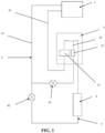
- FIG. 1 and FIG. 2 show a heat exchange system for an outdoor unit of an air conditioner including an outdoor unit heat exchange assembly 3, a first circulation pipeline 2, a control valve assembly, a heating pipeline 5 and a heating assembly 4.
- the outdoor unit heat exchange assembly 3 is disposed at an air conditioner outdoor unit 7.
- the outdoor unit heat exchange assembly 3 includes a coolant heat radiation module 31 and fins 32.
- the first circulation pipeline 2 includes an output pipe 21, a connecting pipe 22 and a return pipe 23.
- the output pipe 21 communicates with an air conditioner indoor unit 1 and the coolant heat radiation module 31, the connecting pipe 22 communicates with the coolant heat radiation module 31 and the fins 32, and the return pipe 23 communicates with the fins 32 and the air conditioner indoor unit 1.
- the control valve assembly is connected with the output pipe 21, and controls an opened-closed state of the first circulation pipeline 2.
- the heating pipeline 5 communicates with the output pipe 21 and the fins 32, communicates with the return pipe 23, and is also connected with the control valve assembly.
- the control valve assembly controls an opened-closed state of the heating pipeline 5.
- the heating assembly 4 is connected with the heating pipeline 5, and is configured to heat a coolant in the heating pipeline 5 before entering the fins 32. In the heating process, the first circulation pipeline 2 is opened through, and in the defrosting process, the first circulation pipeline 2 and the heating pipeline 5 are both opened through, and the heating assembly 4 is started.
- the control valve assembly controls the heating pipeline 5 to be closed off, so that the coolant is prevented from flowing through the heating pipeline 5.
- the first circulation pipeline 2 is opened through, and the coolant normally starts from the air conditioner indoor unit 1, flows through the coolant heat radiation module 31 and the fins 32 to perform heat exchange, and then flows back into the air conditioner indoor unit 1.
- the control valve assembly controls the heating pipeline 5 to be closed off to make a part of coolant to flow through the heating pipeline 5.
- control valve assembly controls the first circulation pipeline 2 to reduce the flow rate flowing through, a part of coolant normally starts from the air conditioner indoor unit 1 through the first circulation pipeline 2, flows through the coolant heat radiation module 31 and the fins 32 to perform heat exchange, and then flows back into the air conditioner indoor unit 1, the other part of coolant passes through the heating pipeline 5, and is heated by the heating assembly 4 in the heating pipeline 5 to form a high-temperature coolant, the high-temperature coolant flows into the fins 32 for heat radiation, to achieve a fast defrosting effect.
- the coolant after heat radiation and the coolant in the first circulation pipeline 2 return to the air conditioner indoor unit 1 through the return pipe 23.
- the high-temperature coolant flows into the outdoor unit after heating and thus avoids a module which may most easily trigger a high-temperature warning, so that a machine halt risk due to triggering a high-temperature warning can be reduced.
- a highest temperature of the coolant at an outlet of the heating assembly 4 does not need to be limited, and heat in the heating assembly 4 can be sufficiently utilized.
- the coolant flowing into the air conditioner outdoor unit does not need to be limited to a highest temperature, the defrosting effect can be well improved, and the time for defrosting can be reduced.
- the control on the coolant can be eliminated, the coolant after defrosting can remain sufficient heat for indoor unit heat exchange, and the system stability during heating can be improved.
- the heating assembly 4 is a phase-change heat storage box, which has an advantage of constant temperature and great heat storage density.
- control valve assembly is controlled by the controller, the controller sends a control signal, and the control valve assembly can be controlled to realize the control on the opened-closed state of the first circulation pipeline 2 and the heating pipeline 5.
- a diameter of the output pipe 21 is greater than a diameter of the heating pipeline 5, which is favorable to ensure sufficient coolant in the first circulation pipeline 2 in the defrosting process, and ensure the heating effect.
- the control valve assembly may include a first valve 61 and a second valve 62.
- the first valve 61 is connected with the output pipe 21 and is configured to control an opened-closed state of the output pipe 21.
- the second valve 62 is connected with the heating pipeline 5 and is configured to control an opened-closed state of the heating pipeline 5.
- One end of the connecting pipe 22 is connected with the coolant heat radiation module 31, the other end of the connecting pipe 22 is connected with the heating pipeline 5, the connecting pipe 22 communicates with the fins 32 through the heating pipeline 5, and the heating pipeline 5 communicates with the return pipe 23 through the fins 32.
- the first valve 61 is completely opened, the second valve 62 is closed, the coolant normally starts from the air conditioner indoor unit 1, flows through the coolant heat radiation module 31 and the fins 32 to perform heat exchange, and then flows back into the air conditioner indoor unit 1.
- the first valve 61 is properly and partially opened, the second valve 62 is opened, a part of coolant normally starts from the air conditioner indoor unit 1 through the circulation pipeline 2, flows through the coolant heat radiation module 31 and the fins 32 to perform heat exchange, and then flows back into the air conditioner indoor unit 1, the other part of coolant passes through the heating pipeline 5 to form a high-temperature coolant after being heated by the heating assembly 4 in the heating pipeline 5, the high-temperature coolant flows into the fins 32 for heat radiation, to achieve a fast defrosting effect.
- the coolant after heat radiation and the coolant in the first circulation pipeline 2 return to the air conditioner indoor unit 1 through the return pipe 23.
- the heating assembly 4 is connected between the second valve 62 and the fins 32.
- the coolant forms the high-temperature coolant after being heated while flowing through the heating assembly 4.
- the first valve 61 and the second valve 62 are stop valves.
- the valves have an excellent sealing effect when being closed.
- the control valve assembly includes a third valve 63.
- the third valve 63 is connected with the output pipe 21 and the heating pipeline 5 at the same time, and the third valve 63 respectively controls opened-closed states of the output pipe 21 and the heating pipeline 5.
- the third valve 63 controls the output pipe 21 to be opened through, and the heating pipeline 5 is blocked.
- the coolant normally starts from the air conditioner indoor unit 1, flows through the coolant heat radiation module 31 and the fins 32 to perform heat exchange, and then flows back into the air conditioner indoor unit 1.
- an outlet portion of the third valve 63 communicating with the output pipe 21 is opened, the output pipe 21 is opened through, the heating pipeline 5 is controlled to be opened through, a part of coolant normally starts from the air conditioner indoor unit 1 through the first circulation pipeline 2, flows through the coolant heat radiation module 31 and the fins 32 to perform heat exchange, and then flows back into the air conditioner indoor unit 1, the other part of coolant passes through the heating pipeline 5 to form a high-temperature coolant after being heated by the heating assembly 4 in the heating pipeline 5, the high-temperature coolant flows into the fins 32 for heat radiation, to achieve a fast defrosting effect.
- the coolant after heat radiation and the coolant in the first circulation pipeline 2 return to the air conditioner indoor unit 1 through the return pipe 23.
- the heating pipeline 5 includes a first heating pipeline 51, a cooling connecting pipeline 52 and a cooling refluxing pipeline 53.
- the first heating pipeline 51 communicates with the third valve 63 and the fins 32.
- the first heating pipeline 51 communicates with the cooling connecting pipeline 52 through the fins 32.
- the cooling connecting pipeline 52 communicates with the fins 32 and the coolant heat radiation module 31.
- the cooling connecting pipeline 52 communicates with the cooling refluxing pipeline 53 through the coolant heat radiation module 31.
- the cooling refluxing pipeline 53 communicates with the coolant heat radiation module 31 and the return pipe 23.
- a part of coolant normally starts from the air conditioner indoor unit 1 through the first circulation pipeline 2, flows through the coolant heat radiation module 31 and the fins 32 to perform heat exchange, and then flows back into the air conditioner indoor unit 1, the other part of coolant passes through the first heating pipeline 51 to flow into the fins 32, and is heated by the heating assembly 4 in the first heating pipeline 51 before flowing into the fins 32 to form a high-temperature coolant, the high-temperature coolant flows into the fins 32 for heat radiation, to achieve a fast defrosting effect. Then, the coolant after heat radiation enters the coolant heat radiation module 31 through the cooling connecting pipeline 52 to perform heat exchange, and then flows into the return pipe 23 through the cooling refluxing pipeline 53.
- the heating pipeline 5 and the first heating pipeline 51 are independent from each other at the coolant heat radiation module 31 and the fins 32, the mutual interference of the coolant in the heating pipeline 5 and the first heating pipeline 51 at the coolant heat radiation module 31 and the fins 32 is small, and the heating function stability can be ensured.
- the exchange system for the outdoor unit of the air conditioner further includes a fourth valve 8.
- the cooling refluxing pipeline 53 communicates with the return pipe 23 through the fourth valve 8, and the fourth valve 8 controls an opened-closed state of the cooling refluxing pipeline 53.
- the fourth valve 8 controls an opened-closed state of the cooling refluxing pipeline 53.
- the cooling refluxing pipeline 53 can be closed off to prevent the coolant in the return pipe 23 from refluxing.
- the fourth valve 8 is a reversing valve.
- the third valve 63 is a reversing valve.
- the reversing valve has the advantages of accurate action, high automation degree, and high work stability and reliability, and is applicable to the exchange system for the outdoor unit of the air conditioner.
- An air conditioner can include a controller, an air conditioner indoor unit 1, an air conditioner outdoor unit 7 and the exchange system for the outdoor unit of the air conditioner.
- the controller is in communicative connection with and controls the control valve assembly;
- the outdoor unit heat exchange assembly 3 is included in the outdoor unit;
- the indoor unit includes a pressure pump, an output end of the pressure pump communicates with the output pipe 21, and an input end of the pressure pump communicates with the return pipe 23. Therefore, the air conditioner also achieves the better defrosting effect while ensuring the heating effect. It can eliminate the need for frequently reversing the compressor.
- the technical problem of damaging user experience and shortening service life of the air conditioner due to frequent reversing of the compressor in the prior art can be solved.
- the present invention has the beneficial effects that the exchange system including an outdoor unit and an air conditioner indoor unit controls the opened-closed states of the first circulation pipeline 2 and the heating pipeline 5 through the control valve assembly, by cooperating with the heating assembly 4, it is possible to provide a high-temperature coolant for the fins 32 in the heating process, and it can achieve a better defrosting effect while ensuring a heating effect, and can eliminate the need for frequently reversing the compressor.
- the technical problem of damaging user experience and shortening service life of the air conditioner due to frequent reversing of the compressor in the prior art can be solved.
Landscapes
- Engineering & Computer Science (AREA)
- Mechanical Engineering (AREA)
- General Engineering & Computer Science (AREA)
- Chemical & Material Sciences (AREA)
- Combustion & Propulsion (AREA)
- Physics & Mathematics (AREA)
- Signal Processing (AREA)
- Thermal Sciences (AREA)
- Fuzzy Systems (AREA)
- Mathematical Physics (AREA)
- Air Conditioning Control Device (AREA)
- Compression-Type Refrigeration Machines With Reversible Cycles (AREA)
Description
- The present invention relates to a heat exchange system for an outdoor unit of an air conditioner and an air conditioner.
- In some areas, when an air conditioner operates to generate heat in winter, the heat absorption temperature of a heat exchanger for an outdoor unit of an air conditioner is reduced, and fins of the heat exchanger for the outdoor unit of the air conditioner are frosted, so that the heat exchange efficiency of the heat exchanger is lowered, and the performance of the air conditioner is reduced. Therefore, when an outdoor unit of an air conditioner is frosted, defrosting is required. Most outdoor units adopt a method of reversing a compressor to enable a heat exchange system to refrigerate, so that high-temperature coolant flows through the heat exchanger of the outdoor unit, but frequent reversing the compressor may damage user experience and shorten the service life of the air conditioner, and a heating effect is easily influenced in the defrosting process.
-
JP 2010 121847 A -
CN 103 383 157 A discloses a system for heating refrigerant fluid with a heater, by directing refrigerant from the outdoor heat exchanger to the heater and providing this hot refrigerant to the indoor heat exchanger for heating up a room. - Viewed from a first aspect, the present invention provides a heat exchange system including an outdoor unit and an air conditioner indoor unit including:
- an outdoor unit heat exchange assembly including a coolant heat radiation module and fins;
- a first circulation pipeline including an output pipe, a connecting pipe and a return pipe, wherein the output pipe communicates with the air conditioner indoor unit and the coolant heat radiation module, the connecting pipe communicates with the coolant heat radiation module and the fins, and the return pipe communicates with the fins and the air conditioner indoor unit;
- a control valve assembly connected with the output pipe and controlling an opened-closed state of the first circulation pipeline;
- a heating pipeline communicating with the output pipe and the fins, and further connected with the control valve assembly, wherein the control valve assembly controls an opened-closed state of the heating pipeline; and
- a heating assembly connected with the heating pipeline and configured to heat a coolant in the heating pipeline before entering the fins.
- The outdoor unit heat exchange assembly of the above aspect may help in avoiding a damaging user experience and reduced service life of an air conditioner due to frequent reversing of a compressor in a defrosting process. The inventors have realised that this can be a problem in the prior art outdoor unit heat exchange assemblies.
- In the heating process, the first circulation pipeline is opened through, and in the defrosting process, the first circulation pipeline and the heating pipeline are both opened through, and the heating assembly is started.
- Optionally, the control valve assembly includes:
- a first valve connected with the output pipe and configured to control an opened-closed state of the output pipe; and
- a second valve connected with the heating pipeline and configured to control an opened-closed state of the heating pipeline.
- Optionally, one end of the connecting pipe is connected with the coolant heat radiation module, the other end of the connecting pipe is connected with the heating pipeline, the connecting pipe communicates with the fins through the heating pipeline, and the heating pipeline communicates with the return pipe through the fins.
- Optionally, the heating assembly is connected between the second valve and the fins.
- Optionally, the first valve and the second valve are stop valves.
- Optionally, the control valve assembly includes:
a third valve connected with the output pipe and the heating pipeline at the same time and configured to respectively control opened-closed states of the output pipe and the heating pipeline. - Optionally, the heating pipeline includes a first heating pipeline, a cooling connecting pipeline and a cooling refluxing pipeline.
- Optionally, the first heating pipeline communicates with the third valve and the fins; the first heating pipeline communicates with the cooling connecting pipeline through the fins; the cooling connecting pipeline communicates with the fins and the coolant heat radiation module; the cooling connecting pipeline communicates with the cooling refluxing pipeline through the coolant heat radiation module; and the cooling refluxing pipeline communicates with the coolant heat radiation module and the return pipe.
- Optionally, the exchange system for the outdoor unit of the air conditioner further includes a fourth valve, wherein the cooling refluxing pipeline communicates with the return pipe through the fourth valve, and the fourth valve controls an opened-closed state of the cooling refluxing pipeline.
- Optionally, the fourth valve is a reversing valve.
- Optionally, the third valve is a reversing valve.
- The invention further extends, in another aspect, to an air conditioner including a controller, and the exchange system for the outdoor unit of the air conditioner.
- Optionally, the controller is in communication connection and controls the control valve assembly.
- Optionally, the outdoor unit heat exchange assembly is included in the outdoor unit.
- Optionally, the indoor unit includes a pressure pump, an output end of the pressure pump communicates with the output pipe, and an input end of the pressure pump communicates with the return pipe.
- The present invention, at least in a preferred embodiment, has the beneficial effects that the exchange system for the outdoor unit of the air conditioner controls opened-closed states of the first circulation pipeline and the heating pipeline through the control valve assembly. By cooperating with the heating assembly, it can provide a high-temperature coolant for the fins in the heating process, can achieve a better defrosting effect while ensuring a heating effect, and can eliminate the need for frequently reversing the compressor. The technical problem of damaging user experience and shortening service life of the air conditioner due to frequent reversing of the compressor in the prior art can be solved.
-
FIG. 1 is a schematic structure diagram of a heat exchange system for an outdoor unit of an air conditioner. -
FIG. 2 is a schematic structure diagram of another heat exchange system for an outdoor unit of an air conditioner. - The implementation of the objectives, the functional features and the advantages of the present invention will be further explained with reference to the accompanying drawings.
- It shall be understood that specific embodiments described herein are merely used to illustrate the present invention, and are not intended to limit the present invention.
-
FIG. 1 andFIG. 2 show a heat exchange system for an outdoor unit of an air conditioner including an outdoor unitheat exchange assembly 3, afirst circulation pipeline 2, a control valve assembly, a heating pipeline 5 and a heating assembly 4. The outdoor unitheat exchange assembly 3 is disposed at an air conditioneroutdoor unit 7. The outdoor unitheat exchange assembly 3 includes a coolantheat radiation module 31 andfins 32. Thefirst circulation pipeline 2 includes anoutput pipe 21, a connectingpipe 22 and areturn pipe 23. Theoutput pipe 21 communicates with an air conditionerindoor unit 1 and the coolantheat radiation module 31, the connectingpipe 22 communicates with the coolantheat radiation module 31 and thefins 32, and thereturn pipe 23 communicates with thefins 32 and the air conditionerindoor unit 1. The control valve assembly is connected with theoutput pipe 21, and controls an opened-closed state of thefirst circulation pipeline 2. The heating pipeline 5 communicates with theoutput pipe 21 and thefins 32, communicates with thereturn pipe 23, and is also connected with the control valve assembly. The control valve assembly controls an opened-closed state of the heating pipeline 5. The heating assembly 4 is connected with the heating pipeline 5, and is configured to heat a coolant in the heating pipeline 5 before entering thefins 32. In the heating process, thefirst circulation pipeline 2 is opened through, and in the defrosting process, thefirst circulation pipeline 2 and the heating pipeline 5 are both opened through, and the heating assembly 4 is started. - Specifically, during normal heating, the control valve assembly controls the heating pipeline 5 to be closed off, so that the coolant is prevented from flowing through the heating pipeline 5. Additionally, the
first circulation pipeline 2 is opened through, and the coolant normally starts from the air conditionerindoor unit 1, flows through the coolantheat radiation module 31 and thefins 32 to perform heat exchange, and then flows back into the air conditionerindoor unit 1. During defrosting, the control valve assembly controls the heating pipeline 5 to be closed off to make a part of coolant to flow through the heating pipeline 5. Additionally, the control valve assembly controls thefirst circulation pipeline 2 to reduce the flow rate flowing through, a part of coolant normally starts from the air conditionerindoor unit 1 through thefirst circulation pipeline 2, flows through the coolantheat radiation module 31 and thefins 32 to perform heat exchange, and then flows back into the air conditionerindoor unit 1, the other part of coolant passes through the heating pipeline 5, and is heated by the heating assembly 4 in the heating pipeline 5 to form a high-temperature coolant, the high-temperature coolant flows into thefins 32 for heat radiation, to achieve a fast defrosting effect. The coolant after heat radiation and the coolant in thefirst circulation pipeline 2 return to the air conditionerindoor unit 1 through thereturn pipe 23. - This advantageously provides the beneficial effects that the exchange system for the outdoor unit of the air conditioner controls the opened-closed states of the
first circulation pipeline 2 and the heating pipeline 5 through the control valve assembly, by cooperating with the heating assembly 4, it is possible to provide high-temperature coolant for thefins 32 in the heating process. A better defrosting effect can be achieved while ensuring the heating effect. It can eliminate the need for frequently reversing the compressor. The technical problem of damaging user experience and shortening service life of the air conditioner due to frequent reversing the compressor in the prior art can be solved. The high-temperature coolant flows into the outdoor unit after heating and thus avoids a module which may most easily trigger a high-temperature warning, so that a machine halt risk due to triggering a high-temperature warning can be reduced. A highest temperature of the coolant at an outlet of the heating assembly 4 does not need to be limited, and heat in the heating assembly 4 can be sufficiently utilized. The coolant flowing into the air conditioner outdoor unit does not need to be limited to a highest temperature, the defrosting effect can be well improved, and the time for defrosting can be reduced. The control on the coolant can be eliminated, the coolant after defrosting can remain sufficient heat for indoor unit heat exchange, and the system stability during heating can be improved. - It shall be noted that the heating assembly 4 is a phase-change heat storage box, which has an advantage of constant temperature and great heat storage density.
- Optionally, the control valve assembly is controlled by the controller, the controller sends a control signal, and the control valve assembly can be controlled to realize the control on the opened-closed state of the
first circulation pipeline 2 and the heating pipeline 5. - Optionally, in a communication position of the heating pipeline 5 and the
output pipe 21, a diameter of theoutput pipe 21 is greater than a diameter of the heating pipeline 5, which is favorable to ensure sufficient coolant in thefirst circulation pipeline 2 in the defrosting process, and ensure the heating effect. - Further, referring to
FIG. 1 , the control valve assembly may include afirst valve 61 and asecond valve 62. Thefirst valve 61 is connected with theoutput pipe 21 and is configured to control an opened-closed state of theoutput pipe 21. Thesecond valve 62 is connected with the heating pipeline 5 and is configured to control an opened-closed state of the heating pipeline 5. One end of the connectingpipe 22 is connected with the coolantheat radiation module 31, the other end of the connectingpipe 22 is connected with the heating pipeline 5, the connectingpipe 22 communicates with thefins 32 through the heating pipeline 5, and the heating pipeline 5 communicates with thereturn pipe 23 through thefins 32. - Specifically, during normal heating, the
first valve 61 is completely opened, thesecond valve 62 is closed, the coolant normally starts from the air conditionerindoor unit 1, flows through the coolantheat radiation module 31 and thefins 32 to perform heat exchange, and then flows back into the air conditionerindoor unit 1. During defrosting, thefirst valve 61 is properly and partially opened, thesecond valve 62 is opened, a part of coolant normally starts from the air conditionerindoor unit 1 through thecirculation pipeline 2, flows through the coolantheat radiation module 31 and thefins 32 to perform heat exchange, and then flows back into the air conditionerindoor unit 1, the other part of coolant passes through the heating pipeline 5 to form a high-temperature coolant after being heated by the heating assembly 4 in the heating pipeline 5, the high-temperature coolant flows into thefins 32 for heat radiation, to achieve a fast defrosting effect. The coolant after heat radiation and the coolant in thefirst circulation pipeline 2 return to the air conditionerindoor unit 1 through thereturn pipe 23. - Optionally, the heating assembly 4 is connected between the
second valve 62 and thefins 32. The coolant forms the high-temperature coolant after being heated while flowing through the heating assembly 4. - Optionally, the
first valve 61 and thesecond valve 62 are stop valves. The valves have an excellent sealing effect when being closed. - Optionally, referring to
FIG. 2 , the control valve assembly includes athird valve 63. Thethird valve 63 is connected with theoutput pipe 21 and the heating pipeline 5 at the same time, and thethird valve 63 respectively controls opened-closed states of theoutput pipe 21 and the heating pipeline 5. - Specifically, during normal heating, the
third valve 63 controls theoutput pipe 21 to be opened through, and the heating pipeline 5 is blocked. The coolant normally starts from the air conditionerindoor unit 1, flows through the coolantheat radiation module 31 and thefins 32 to perform heat exchange, and then flows back into the air conditionerindoor unit 1. During defrosting, an outlet portion of thethird valve 63 communicating with theoutput pipe 21 is opened, theoutput pipe 21 is opened through, the heating pipeline 5 is controlled to be opened through, a part of coolant normally starts from the air conditionerindoor unit 1 through thefirst circulation pipeline 2, flows through the coolantheat radiation module 31 and thefins 32 to perform heat exchange, and then flows back into the air conditionerindoor unit 1, the other part of coolant passes through the heating pipeline 5 to form a high-temperature coolant after being heated by the heating assembly 4 in the heating pipeline 5, the high-temperature coolant flows into thefins 32 for heat radiation, to achieve a fast defrosting effect. The coolant after heat radiation and the coolant in thefirst circulation pipeline 2 return to the air conditionerindoor unit 1 through thereturn pipe 23. - Optionally, the heating pipeline 5 includes a first heating pipeline 51, a
cooling connecting pipeline 52 and a coolingrefluxing pipeline 53. The first heating pipeline 51 communicates with thethird valve 63 and thefins 32. The first heating pipeline 51 communicates with thecooling connecting pipeline 52 through thefins 32. The cooling connectingpipeline 52 communicates with thefins 32 and the coolantheat radiation module 31. The cooling connectingpipeline 52 communicates with the coolingrefluxing pipeline 53 through the coolantheat radiation module 31. The coolingrefluxing pipeline 53 communicates with the coolantheat radiation module 31 and thereturn pipe 23. - Specifically, during defrosting, a part of coolant normally starts from the air conditioner
indoor unit 1 through thefirst circulation pipeline 2, flows through the coolantheat radiation module 31 and thefins 32 to perform heat exchange, and then flows back into the air conditionerindoor unit 1, the other part of coolant passes through the first heating pipeline 51 to flow into thefins 32, and is heated by the heating assembly 4 in the first heating pipeline 51 before flowing into thefins 32 to form a high-temperature coolant, the high-temperature coolant flows into thefins 32 for heat radiation, to achieve a fast defrosting effect. Then, the coolant after heat radiation enters the coolantheat radiation module 31 through thecooling connecting pipeline 52 to perform heat exchange, and then flows into thereturn pipe 23 through the coolingrefluxing pipeline 53. The heating pipeline 5 and the first heating pipeline 51 are independent from each other at the coolantheat radiation module 31 and thefins 32, the mutual interference of the coolant in the heating pipeline 5 and the first heating pipeline 51 at the coolantheat radiation module 31 and thefins 32 is small, and the heating function stability can be ensured. - Optionally, the exchange system for the outdoor unit of the air conditioner further includes a fourth valve 8. The cooling
refluxing pipeline 53 communicates with thereturn pipe 23 through the fourth valve 8, and the fourth valve 8 controls an opened-closed state of the coolingrefluxing pipeline 53. Through the fourth valve 8, during normal heating, the coolingrefluxing pipeline 53 can be closed off to prevent the coolant in thereturn pipe 23 from refluxing. - Optionally, the fourth valve 8 is a reversing valve.
- Optionally, the
third valve 63 is a reversing valve. The reversing valve has the advantages of accurate action, high automation degree, and high work stability and reliability, and is applicable to the exchange system for the outdoor unit of the air conditioner. - An air conditioner can include a controller, an air conditioner
indoor unit 1, an air conditioneroutdoor unit 7 and the exchange system for the outdoor unit of the air conditioner. The controller is in communicative connection with and controls the control valve assembly; the outdoor unitheat exchange assembly 3 is included in the outdoor unit; and the indoor unit includes a pressure pump, an output end of the pressure pump communicates with theoutput pipe 21, and an input end of the pressure pump communicates with thereturn pipe 23. Therefore, the air conditioner also achieves the better defrosting effect while ensuring the heating effect. It can eliminate the need for frequently reversing the compressor. The technical problem of damaging user experience and shortening service life of the air conditioner due to frequent reversing of the compressor in the prior art can be solved. - The present invention, at least in the embodiments above, has the beneficial effects that the exchange system including an outdoor unit and an air conditioner indoor unit controls the opened-closed states of the
first circulation pipeline 2 and the heating pipeline 5 through the control valve assembly, by cooperating with the heating assembly 4, it is possible to provide a high-temperature coolant for thefins 32 in the heating process, and it can achieve a better defrosting effect while ensuring a heating effect, and can eliminate the need for frequently reversing the compressor. The technical problem of damaging user experience and shortening service life of the air conditioner due to frequent reversing of the compressor in the prior art can be solved. - The above descriptions are only exemplary embodiments of the present invention, and thus do not limit the scope of the present invention, which is defined by the claims.
Claims (11)
- A heat exchange system including an outdoor unit and an air conditioner indoor unit (1), comprising:an outdoor unit heat exchange assembly (3) comprising a coolant heat radiation module (31) and fins (32);a first circulation pipeline (2) comprising an output pipe (21), a connecting pipe (22) and a return pipe (23), wherein the output pipe (21) communicates with an air conditioner indoor unit (1) and the coolant heat radiation module (31), the connecting pipe (22) communicates with the coolant heat radiation module (31) and the fins (32), and the return pipe (23) communicates with the fins (32) and the air conditioner indoor unit (1);a control valve assembly (61, 62) connected with the output pipe (21) and controlling an opened-closed state of the first circulation pipeline (2);a heating pipeline (5) communicating with the output pipe (21) and the fins (32), and further connected with the control valve assembly (61, 62), wherein the control valve assembly (61, 62) controls an opened-closed state of the heating pipeline (5); anda heating assembly (4) connected with the heating pipeline (5) and configured to heat a coolant in the heating pipeline (5) before entering the fins (32), whereinin the heating process, the first circulation pipeline (2) is opened through, and in the defrosting process, the first circulation pipeline (2) and the heating pipeline (5) are both opened through, and the heating assembly (4) is started.
- The heat exchange system according to claim 1, wherein the control valve assembly (61, 62) comprises:a first valve (61) connected with the output pipe (21) and configured to control an opened-closed state of the output pipe (21); anda second valve (62) connected with the heating pipeline (5) and configured to control an opened-closed state of the heating pipeline (5); andone end of the connecting pipe (22) is connected with the coolant heat radiation module (31), the other end of the connecting pipe (22) is connected with the heating pipeline (5), the connecting pipe (22) communicates with the fins (32) through the heating pipeline (5), and the heating pipeline (5) communicates with the return pipe (23) through the fins (32).
- The heat exchange system according to claim 2, wherein the heating assembly (4) is connected between the second valve (62) and the fins (32).
- The heat exchange system according to claim 2, wherein the first valve (61) and the second valve (62) are stop valves.
- The heat exchange system according to any preceding claim, wherein the control valve assembly comprises:
a third valve (63) connected with the output pipe (21) and the heating pipeline (5) at the same time and configured to respectively control opened-closed states of the output pipe (21) and the heating pipeline (5). - The heat exchange system according to claim 5, wherein the heating pipeline (5) comprises a first heating pipeline (51), a cooling connecting pipeline (52) and a cooling refluxing pipeline (53);
the first heating pipeline (51) communicates with the third valve (63) and the fins (32); the first heating pipeline (51) communicates with the cooling connecting pipeline (52) through the fins (32); the cooling connecting pipeline (52) communicates with the fins (32) and the coolant heat radiation module (31); the cooling connecting pipeline (52) communicates with the cooling refluxing pipeline (53) through the coolant heat radiation module (31); and the cooling refluxing pipeline (53) communicates with the coolant heat radiation module (31) and the return pipe (23). - The heat exchange system according to claim 6, further comprising a fourth valve (8), wherein the cooling refluxing pipeline (53) communicates with the return pipe (23) through the fourth valve (8), and the fourth valve (8) controls an opened-closed state of the cooling refluxing pipeline (53).
- The heat exchange system according to claim 7, wherein the fourth valve (8) is a reversing valve.
- The heat exchange system according to any of claims 5 to 8, wherein the third valve (63) is a reversing valve.
- An air conditioner, comprising a controller and the heat exchange system according to any preceding claim.
- The air conditioner of claim 10, wherein:the controller is in communicative connection with and controls the control valve assembly;the outdoor unit heat exchange assembly (3) is comprised in the outdoor unit (7); andthe indoor unit (1) comprises a pressure pump, an output end of the pressure pump communicates with the output pipe (21), and an input end of the pressure pump communicates with the return pipe (23).
Applications Claiming Priority (1)
| Application Number | Priority Date | Filing Date | Title |
|---|---|---|---|
| CN202010752843.2A CN112032854A (en) | 2020-07-30 | 2020-07-30 | Outer quick-witted heat transfer system of air conditioner and air conditioner |
Publications (2)
| Publication Number | Publication Date |
|---|---|
| EP3945251A1 EP3945251A1 (en) | 2022-02-02 |
| EP3945251B1 true EP3945251B1 (en) | 2023-08-30 |
Family
ID=73583596
Family Applications (1)
| Application Number | Title | Priority Date | Filing Date |
|---|---|---|---|
| EP21188041.4A Active EP3945251B1 (en) | 2020-07-30 | 2021-07-27 | Heat exchange system comprising an outdoor unit and an air conditioner indoor unit |
Country Status (3)
| Country | Link |
|---|---|
| US (1) | US11774131B2 (en) |
| EP (1) | EP3945251B1 (en) |
| CN (1) | CN112032854A (en) |
Family Cites Families (12)
| Publication number | Priority date | Publication date | Assignee | Title |
|---|---|---|---|---|
| JPS5895140A (en) * | 1981-11-30 | 1983-06-06 | Toho Gas Kk | air conditioning system |
| JPH01172277A (en) * | 1987-12-26 | 1989-07-07 | Toko Inc | Production of ceramic substrate |
| JPH1172277A (en) | 1997-08-29 | 1999-03-16 | Daikin Ind Ltd | Storage type air conditioner |
| JP5478055B2 (en) * | 2008-11-19 | 2014-04-23 | 日立アプライアンス株式会社 | Air conditioner |
| CN201662273U (en) * | 2010-04-07 | 2010-12-01 | 宁波奥克斯空调有限公司 | Unremittingly heating and defrosting heat pump type air conditioner |
| CN103383157B (en) * | 2013-06-28 | 2016-01-13 | 美的集团股份有限公司 | Heat pump type air conditioning system and control method thereof |
| CN104697251B (en) * | 2013-12-10 | 2018-04-27 | 苏州三星电子有限公司 | A kind of refrigerator refrigeration system and refrigerator |
| WO2016046927A1 (en) | 2014-09-25 | 2016-03-31 | 三菱電機株式会社 | Refrigeration cycle device and air-conditioning device |
| CN104764112B (en) * | 2015-04-19 | 2018-04-03 | 上海交通大学 | The air-conditioning system of indoor continuously heating during a kind of defrosting |
| CN105485988A (en) * | 2016-01-14 | 2016-04-13 | 广东美的制冷设备有限公司 | Air conditioner system and defrosting control method thereof |
| CN110469969B (en) * | 2019-07-25 | 2022-09-06 | 青岛海尔空调器有限总公司 | Control method and device for defrosting of air conditioner and air conditioner |
| CN111076446A (en) * | 2019-12-02 | 2020-04-28 | 珠海格力电器股份有限公司 | Heat pump air conditioning system and control method thereof |
-
2020
- 2020-07-30 CN CN202010752843.2A patent/CN112032854A/en active Pending
-
2021
- 2021-07-20 US US17/380,651 patent/US11774131B2/en active Active
- 2021-07-27 EP EP21188041.4A patent/EP3945251B1/en active Active
Also Published As
| Publication number | Publication date |
|---|---|
| US20220034545A1 (en) | 2022-02-03 |
| CN112032854A (en) | 2020-12-04 |
| US11774131B2 (en) | 2023-10-03 |
| EP3945251A1 (en) | 2022-02-02 |
Similar Documents
| Publication | Publication Date | Title |
|---|---|---|
| KR101548416B1 (en) | Heat pump type hot water supply heater | |
| CN102116515A (en) | Intelligent control method for cooling and heating recovery mode of air conditioning unit | |
| JP2013221650A (en) | Refrigeration cycle device | |
| CN114909699B (en) | Defrosting control method, central controller and heating system | |
| EP4130599B1 (en) | Heat pump hot water supply device | |
| CN112984799A (en) | Air energy water heater and control method thereof | |
| CN210197765U (en) | Machine tool cooling unit | |
| CN113864925B (en) | Air conditioner | |
| EP3945251A1 (en) | Heat exchange system for outdoor unit of air conditioner and air conditioner | |
| CN104075421A (en) | Hot-water device for air conditioner | |
| CN120194355A (en) | Hybrid systems for room heating and/or domestic water production and related management methods | |
| KR101533112B1 (en) | Heat pump system and method for controlling the same | |
| CN218600034U (en) | Air source heat pump water chiller-heater unit | |
| CN113978734B (en) | Comprehensive heat pump type air conditioning system | |
| CN216481605U (en) | Heat pump hot water system | |
| CN214746484U (en) | Air energy water heater | |
| CN213020401U (en) | Heating defrosting air source hot water pump | |
| CN216307942U (en) | Electromagnetic valve assembly device for improving heat efficiency of heat pump heating system | |
| KR102172647B1 (en) | Energy Saving Fan Coil Unit | |
| CN211451471U (en) | Bypass throttling component for air source heat pump system | |
| JP2006090620A (en) | Heat medium piping system | |
| JP3175080B2 (en) | Hot water supply system | |
| CN218937149U (en) | Automatic control device of cooling tower | |
| CN119713437B (en) | Air conditioning systems and their control methods | |
| CN222634838U (en) | Heat exchange system and heating ventilation equipment |
Legal Events
| Date | Code | Title | Description |
|---|---|---|---|
| PUAI | Public reference made under article 153(3) epc to a published international application that has entered the european phase |
Free format text: ORIGINAL CODE: 0009012 |
|
| STAA | Information on the status of an ep patent application or granted ep patent |
Free format text: STATUS: THE APPLICATION HAS BEEN PUBLISHED |
|
| AK | Designated contracting states |
Kind code of ref document: A1 Designated state(s): AL AT BE BG CH CY CZ DE DK EE ES FI FR GB GR HR HU IE IS IT LI LT LU LV MC MK MT NL NO PL PT RO RS SE SI SK SM TR |
|
| STAA | Information on the status of an ep patent application or granted ep patent |
Free format text: STATUS: REQUEST FOR EXAMINATION WAS MADE |
|
| 17P | Request for examination filed |
Effective date: 20220302 |
|
| RBV | Designated contracting states (corrected) |
Designated state(s): AL AT BE BG CH CY CZ DE DK EE ES FI FR GB GR HR HU IE IS IT LI LT LU LV MC MK MT NL NO PL PT RO RS SE SI SK SM TR |
|
| GRAP | Despatch of communication of intention to grant a patent |
Free format text: ORIGINAL CODE: EPIDOSNIGR1 |
|
| STAA | Information on the status of an ep patent application or granted ep patent |
Free format text: STATUS: GRANT OF PATENT IS INTENDED |
|
| RIC1 | Information provided on ipc code assigned before grant |
Ipc: F25B 47/02 20060101ALI20230214BHEP Ipc: F24F 11/873 20180101ALI20230214BHEP Ipc: F24F 11/84 20180101ALI20230214BHEP Ipc: F24F 11/42 20180101ALI20230214BHEP Ipc: F24F 1/16 20110101AFI20230214BHEP |
|
| INTG | Intention to grant announced |
Effective date: 20230315 |
|
| GRAS | Grant fee paid |
Free format text: ORIGINAL CODE: EPIDOSNIGR3 |
|
| GRAA | (expected) grant |
Free format text: ORIGINAL CODE: 0009210 |
|
| STAA | Information on the status of an ep patent application or granted ep patent |
Free format text: STATUS: THE PATENT HAS BEEN GRANTED |
|
| AK | Designated contracting states |
Kind code of ref document: B1 Designated state(s): AL AT BE BG CH CY CZ DE DK EE ES FI FR GB GR HR HU IE IS IT LI LT LU LV MC MK MT NL NO PL PT RO RS SE SI SK SM TR |
|
| REG | Reference to a national code |
Ref country code: GB Ref legal event code: FG4D |
|
| REG | Reference to a national code |
Ref country code: CH Ref legal event code: EP |
|
| REG | Reference to a national code |
Ref country code: DE Ref legal event code: R096 Ref document number: 602021004670 Country of ref document: DE |
|
| REG | Reference to a national code |
Ref country code: IE Ref legal event code: FG4D |
|
| REG | Reference to a national code |
Ref country code: NL Ref legal event code: FP |
|
| REG | Reference to a national code |
Ref country code: LT Ref legal event code: MG9D |
|
| REG | Reference to a national code |
Ref country code: AT Ref legal event code: MK05 Ref document number: 1605899 Country of ref document: AT Kind code of ref document: T Effective date: 20230830 |
|
| PG25 | Lapsed in a contracting state [announced via postgrant information from national office to epo] |
Ref country code: GR Free format text: LAPSE BECAUSE OF FAILURE TO SUBMIT A TRANSLATION OF THE DESCRIPTION OR TO PAY THE FEE WITHIN THE PRESCRIBED TIME-LIMIT Effective date: 20231201 |
|
| PG25 | Lapsed in a contracting state [announced via postgrant information from national office to epo] |
Ref country code: IS Free format text: LAPSE BECAUSE OF FAILURE TO SUBMIT A TRANSLATION OF THE DESCRIPTION OR TO PAY THE FEE WITHIN THE PRESCRIBED TIME-LIMIT Effective date: 20231230 |
|
| PG25 | Lapsed in a contracting state [announced via postgrant information from national office to epo] |
Ref country code: SE Free format text: LAPSE BECAUSE OF FAILURE TO SUBMIT A TRANSLATION OF THE DESCRIPTION OR TO PAY THE FEE WITHIN THE PRESCRIBED TIME-LIMIT Effective date: 20230830 Ref country code: RS Free format text: LAPSE BECAUSE OF FAILURE TO SUBMIT A TRANSLATION OF THE DESCRIPTION OR TO PAY THE FEE WITHIN THE PRESCRIBED TIME-LIMIT Effective date: 20230830 Ref country code: NO Free format text: LAPSE BECAUSE OF FAILURE TO SUBMIT A TRANSLATION OF THE DESCRIPTION OR TO PAY THE FEE WITHIN THE PRESCRIBED TIME-LIMIT Effective date: 20231130 Ref country code: LV Free format text: LAPSE BECAUSE OF FAILURE TO SUBMIT A TRANSLATION OF THE DESCRIPTION OR TO PAY THE FEE WITHIN THE PRESCRIBED TIME-LIMIT Effective date: 20230830 Ref country code: LT Free format text: LAPSE BECAUSE OF FAILURE TO SUBMIT A TRANSLATION OF THE DESCRIPTION OR TO PAY THE FEE WITHIN THE PRESCRIBED TIME-LIMIT Effective date: 20230830 Ref country code: IS Free format text: LAPSE BECAUSE OF FAILURE TO SUBMIT A TRANSLATION OF THE DESCRIPTION OR TO PAY THE FEE WITHIN THE PRESCRIBED TIME-LIMIT Effective date: 20231230 Ref country code: HR Free format text: LAPSE BECAUSE OF FAILURE TO SUBMIT A TRANSLATION OF THE DESCRIPTION OR TO PAY THE FEE WITHIN THE PRESCRIBED TIME-LIMIT Effective date: 20230830 Ref country code: GR Free format text: LAPSE BECAUSE OF FAILURE TO SUBMIT A TRANSLATION OF THE DESCRIPTION OR TO PAY THE FEE WITHIN THE PRESCRIBED TIME-LIMIT Effective date: 20231201 Ref country code: FI Free format text: LAPSE BECAUSE OF FAILURE TO SUBMIT A TRANSLATION OF THE DESCRIPTION OR TO PAY THE FEE WITHIN THE PRESCRIBED TIME-LIMIT Effective date: 20230830 Ref country code: AT Free format text: LAPSE BECAUSE OF FAILURE TO SUBMIT A TRANSLATION OF THE DESCRIPTION OR TO PAY THE FEE WITHIN THE PRESCRIBED TIME-LIMIT Effective date: 20230830 |
|
| PG25 | Lapsed in a contracting state [announced via postgrant information from national office to epo] |
Ref country code: PL Free format text: LAPSE BECAUSE OF FAILURE TO SUBMIT A TRANSLATION OF THE DESCRIPTION OR TO PAY THE FEE WITHIN THE PRESCRIBED TIME-LIMIT Effective date: 20230830 |
|
| PG25 | Lapsed in a contracting state [announced via postgrant information from national office to epo] |
Ref country code: ES Free format text: LAPSE BECAUSE OF FAILURE TO SUBMIT A TRANSLATION OF THE DESCRIPTION OR TO PAY THE FEE WITHIN THE PRESCRIBED TIME-LIMIT Effective date: 20230830 |
|
| PG25 | Lapsed in a contracting state [announced via postgrant information from national office to epo] |
Ref country code: SM Free format text: LAPSE BECAUSE OF FAILURE TO SUBMIT A TRANSLATION OF THE DESCRIPTION OR TO PAY THE FEE WITHIN THE PRESCRIBED TIME-LIMIT Effective date: 20230830 Ref country code: RO Free format text: LAPSE BECAUSE OF FAILURE TO SUBMIT A TRANSLATION OF THE DESCRIPTION OR TO PAY THE FEE WITHIN THE PRESCRIBED TIME-LIMIT Effective date: 20230830 Ref country code: ES Free format text: LAPSE BECAUSE OF FAILURE TO SUBMIT A TRANSLATION OF THE DESCRIPTION OR TO PAY THE FEE WITHIN THE PRESCRIBED TIME-LIMIT Effective date: 20230830 Ref country code: EE Free format text: LAPSE BECAUSE OF FAILURE TO SUBMIT A TRANSLATION OF THE DESCRIPTION OR TO PAY THE FEE WITHIN THE PRESCRIBED TIME-LIMIT Effective date: 20230830 Ref country code: DK Free format text: LAPSE BECAUSE OF FAILURE TO SUBMIT A TRANSLATION OF THE DESCRIPTION OR TO PAY THE FEE WITHIN THE PRESCRIBED TIME-LIMIT Effective date: 20230830 Ref country code: CZ Free format text: LAPSE BECAUSE OF FAILURE TO SUBMIT A TRANSLATION OF THE DESCRIPTION OR TO PAY THE FEE WITHIN THE PRESCRIBED TIME-LIMIT Effective date: 20230830 Ref country code: SK Free format text: LAPSE BECAUSE OF FAILURE TO SUBMIT A TRANSLATION OF THE DESCRIPTION OR TO PAY THE FEE WITHIN THE PRESCRIBED TIME-LIMIT Effective date: 20230830 Ref country code: PT Free format text: LAPSE BECAUSE OF FAILURE TO SUBMIT A TRANSLATION OF THE DESCRIPTION OR TO PAY THE FEE WITHIN THE PRESCRIBED TIME-LIMIT Effective date: 20240102 |
|
| REG | Reference to a national code |
Ref country code: DE Ref legal event code: R097 Ref document number: 602021004670 Country of ref document: DE |
|
| PLBE | No opposition filed within time limit |
Free format text: ORIGINAL CODE: 0009261 |
|
| STAA | Information on the status of an ep patent application or granted ep patent |
Free format text: STATUS: NO OPPOSITION FILED WITHIN TIME LIMIT |
|
| PG25 | Lapsed in a contracting state [announced via postgrant information from national office to epo] |
Ref country code: SI Free format text: LAPSE BECAUSE OF FAILURE TO SUBMIT A TRANSLATION OF THE DESCRIPTION OR TO PAY THE FEE WITHIN THE PRESCRIBED TIME-LIMIT Effective date: 20230830 |
|
| 26N | No opposition filed |
Effective date: 20240603 |
|
| PG25 | Lapsed in a contracting state [announced via postgrant information from national office to epo] |
Ref country code: BG Free format text: LAPSE BECAUSE OF FAILURE TO SUBMIT A TRANSLATION OF THE DESCRIPTION OR TO PAY THE FEE WITHIN THE PRESCRIBED TIME-LIMIT Effective date: 20230830 |
|
| PG25 | Lapsed in a contracting state [announced via postgrant information from national office to epo] |
Ref country code: BG Free format text: LAPSE BECAUSE OF FAILURE TO SUBMIT A TRANSLATION OF THE DESCRIPTION OR TO PAY THE FEE WITHIN THE PRESCRIBED TIME-LIMIT Effective date: 20230830 |
|
| PG25 | Lapsed in a contracting state [announced via postgrant information from national office to epo] |
Ref country code: MC Free format text: LAPSE BECAUSE OF FAILURE TO SUBMIT A TRANSLATION OF THE DESCRIPTION OR TO PAY THE FEE WITHIN THE PRESCRIBED TIME-LIMIT Effective date: 20230830 |
|
| REG | Reference to a national code |
Ref country code: CH Ref legal event code: PL |
|
| REG | Reference to a national code |
Ref country code: NL Ref legal event code: MM Effective date: 20240801 |
|
| PG25 | Lapsed in a contracting state [announced via postgrant information from national office to epo] |
Ref country code: LU Free format text: LAPSE BECAUSE OF NON-PAYMENT OF DUE FEES Effective date: 20240727 |
|
| PG25 | Lapsed in a contracting state [announced via postgrant information from national office to epo] |
Ref country code: LU Free format text: LAPSE BECAUSE OF NON-PAYMENT OF DUE FEES Effective date: 20240727 |
|
| PG25 | Lapsed in a contracting state [announced via postgrant information from national office to epo] |
Ref country code: NL Free format text: LAPSE BECAUSE OF NON-PAYMENT OF DUE FEES Effective date: 20240801 |
|
| PG25 | Lapsed in a contracting state [announced via postgrant information from national office to epo] |
Ref country code: CH Free format text: LAPSE BECAUSE OF NON-PAYMENT OF DUE FEES Effective date: 20240731 Ref country code: BE Free format text: LAPSE BECAUSE OF NON-PAYMENT OF DUE FEES Effective date: 20240731 |
|
| REG | Reference to a national code |
Ref country code: BE Ref legal event code: MM Effective date: 20240731 |
|
| PGFP | Annual fee paid to national office [announced via postgrant information from national office to epo] |
Ref country code: FR Payment date: 20250620 Year of fee payment: 5 |
|
| PG25 | Lapsed in a contracting state [announced via postgrant information from national office to epo] |
Ref country code: IE Free format text: LAPSE BECAUSE OF NON-PAYMENT OF DUE FEES Effective date: 20240727 |
|
| PGFP | Annual fee paid to national office [announced via postgrant information from national office to epo] |
Ref country code: DE Payment date: 20250620 Year of fee payment: 5 |
|
| PGFP | Annual fee paid to national office [announced via postgrant information from national office to epo] |
Ref country code: IT Payment date: 20250619 Year of fee payment: 5 |
|
| PG25 | Lapsed in a contracting state [announced via postgrant information from national office to epo] |
Ref country code: CY Free format text: LAPSE BECAUSE OF FAILURE TO SUBMIT A TRANSLATION OF THE DESCRIPTION OR TO PAY THE FEE WITHIN THE PRESCRIBED TIME-LIMIT; INVALID AB INITIO Effective date: 20210727 |
|
| PG25 | Lapsed in a contracting state [announced via postgrant information from national office to epo] |
Ref country code: HU Free format text: LAPSE BECAUSE OF FAILURE TO SUBMIT A TRANSLATION OF THE DESCRIPTION OR TO PAY THE FEE WITHIN THE PRESCRIBED TIME-LIMIT; INVALID AB INITIO Effective date: 20210727 |
|
| GBPC | Gb: european patent ceased through non-payment of renewal fee |
Effective date: 20250727 |
|
| PG25 | Lapsed in a contracting state [announced via postgrant information from national office to epo] |
Ref country code: GB Free format text: LAPSE BECAUSE OF NON-PAYMENT OF DUE FEES Effective date: 20250727 |