EP3945242A1 - Head lamp for vehicle - Google Patents
Head lamp for vehicle Download PDFInfo
- Publication number
- EP3945242A1 EP3945242A1 EP21188160.2A EP21188160A EP3945242A1 EP 3945242 A1 EP3945242 A1 EP 3945242A1 EP 21188160 A EP21188160 A EP 21188160A EP 3945242 A1 EP3945242 A1 EP 3945242A1
- Authority
- EP
- European Patent Office
- Prior art keywords
- flip
- vehicle
- head lamp
- lamp
- housing
- Prior art date
- Legal status (The legal status is an assumption and is not a legal conclusion. Google has not performed a legal analysis and makes no representation as to the accuracy of the status listed.)
- Granted
Links
Images



Classifications
-
- F—MECHANICAL ENGINEERING; LIGHTING; HEATING; WEAPONS; BLASTING
- F21—LIGHTING
- F21S—NON-PORTABLE LIGHTING DEVICES; SYSTEMS THEREOF; VEHICLE LIGHTING DEVICES SPECIALLY ADAPTED FOR VEHICLE EXTERIORS
- F21S41/00—Illuminating devices specially adapted for vehicle exteriors, e.g. headlamps
- F21S41/50—Illuminating devices specially adapted for vehicle exteriors, e.g. headlamps characterised by aesthetic components not otherwise provided for, e.g. decorative trim, partition walls or covers
-
- F—MECHANICAL ENGINEERING; LIGHTING; HEATING; WEAPONS; BLASTING
- F21—LIGHTING
- F21S—NON-PORTABLE LIGHTING DEVICES; SYSTEMS THEREOF; VEHICLE LIGHTING DEVICES SPECIALLY ADAPTED FOR VEHICLE EXTERIORS
- F21S45/00—Arrangements within vehicle lighting devices specially adapted for vehicle exteriors, for purposes other than emission or distribution of light
- F21S45/20—Promoting gas flow in lighting devices, e.g. directing flow toward the cover glass for demisting
-
- F—MECHANICAL ENGINEERING; LIGHTING; HEATING; WEAPONS; BLASTING
- F21—LIGHTING
- F21S—NON-PORTABLE LIGHTING DEVICES; SYSTEMS THEREOF; VEHICLE LIGHTING DEVICES SPECIALLY ADAPTED FOR VEHICLE EXTERIORS
- F21S41/00—Illuminating devices specially adapted for vehicle exteriors, e.g. headlamps
- F21S41/40—Illuminating devices specially adapted for vehicle exteriors, e.g. headlamps characterised by screens, non-reflecting members, light-shielding members or fixed shades
-
- F—MECHANICAL ENGINEERING; LIGHTING; HEATING; WEAPONS; BLASTING
- F21—LIGHTING
- F21S—NON-PORTABLE LIGHTING DEVICES; SYSTEMS THEREOF; VEHICLE LIGHTING DEVICES SPECIALLY ADAPTED FOR VEHICLE EXTERIORS
- F21S45/00—Arrangements within vehicle lighting devices specially adapted for vehicle exteriors, for purposes other than emission or distribution of light
- F21S45/30—Ventilation or drainage of lighting devices
- F21S45/33—Ventilation or drainage of lighting devices specially adapted for headlamps
-
- F—MECHANICAL ENGINEERING; LIGHTING; HEATING; WEAPONS; BLASTING
- F21—LIGHTING
- F21S—NON-PORTABLE LIGHTING DEVICES; SYSTEMS THEREOF; VEHICLE LIGHTING DEVICES SPECIALLY ADAPTED FOR VEHICLE EXTERIORS
- F21S45/00—Arrangements within vehicle lighting devices specially adapted for vehicle exteriors, for purposes other than emission or distribution of light
- F21S45/40—Cooling of lighting devices
-
- F—MECHANICAL ENGINEERING; LIGHTING; HEATING; WEAPONS; BLASTING
- F21—LIGHTING
- F21S—NON-PORTABLE LIGHTING DEVICES; SYSTEMS THEREOF; VEHICLE LIGHTING DEVICES SPECIALLY ADAPTED FOR VEHICLE EXTERIORS
- F21S45/00—Arrangements within vehicle lighting devices specially adapted for vehicle exteriors, for purposes other than emission or distribution of light
- F21S45/50—Waterproofing
-
- G—PHYSICS
- G09—EDUCATION; CRYPTOGRAPHY; DISPLAY; ADVERTISING; SEALS
- G09F—DISPLAYING; ADVERTISING; SIGNS; LABELS OR NAME-PLATES; SEALS
- G09F21/00—Mobile visual advertising
- G09F21/04—Mobile visual advertising by land vehicles
-
- G—PHYSICS
- G09—EDUCATION; CRYPTOGRAPHY; DISPLAY; ADVERTISING; SEALS
- G09F—DISPLAYING; ADVERTISING; SIGNS; LABELS OR NAME-PLATES; SEALS
- G09F9/00—Indicating arrangements for variable information in which the information is built-up on a support by selection or combination of individual elements
- G09F9/30—Indicating arrangements for variable information in which the information is built-up on a support by selection or combination of individual elements in which the desired character or characters are formed by combining individual elements
- G09F9/37—Indicating arrangements for variable information in which the information is built-up on a support by selection or combination of individual elements in which the desired character or characters are formed by combining individual elements being movable elements
- G09F9/375—Indicating arrangements for variable information in which the information is built-up on a support by selection or combination of individual elements in which the desired character or characters are formed by combining individual elements being movable elements the position of the elements being controlled by the application of a magnetic field
-
- F—MECHANICAL ENGINEERING; LIGHTING; HEATING; WEAPONS; BLASTING
- F21—LIGHTING
- F21W—INDEXING SCHEME ASSOCIATED WITH SUBCLASSES F21K, F21L, F21S and F21V, RELATING TO USES OR APPLICATIONS OF LIGHTING DEVICES OR SYSTEMS
- F21W2102/00—Exterior vehicle lighting devices for illuminating purposes
-
- F—MECHANICAL ENGINEERING; LIGHTING; HEATING; WEAPONS; BLASTING
- F21—LIGHTING
- F21W—INDEXING SCHEME ASSOCIATED WITH SUBCLASSES F21K, F21L, F21S and F21V, RELATING TO USES OR APPLICATIONS OF LIGHTING DEVICES OR SYSTEMS
- F21W2107/00—Use or application of lighting devices on or in particular types of vehicles
- F21W2107/10—Use or application of lighting devices on or in particular types of vehicles for land vehicles
Definitions
- Exemplary embodiments of the present disclosure relate to a head lamp for a vehicle, and more particularly, to a head lamp for a vehicle, which includes a flip-dot unit installed in a lamp housing in order to prevent overheat and moisture in the lamp housing and to effectively inform an oncoming vehicle or pedestrian of notice information on the state of a vehicle or notice information related to the driving of the vehicle.
- a head lamp of the vehicle emits light to the forward area of the vehicle such that a driver can easily check and identify an object ahead of vehicle.
- the head lamp is typically installed on either side of the front of the vehicle.
- the head lamp of the vehicle uses two light sources to adjust the brightness of light, when illuminating the forward area of the vehicle. Any one of the light sources is used as a low beam capable of illuminating an area at a relatively small distance, and the other of the light sources is used as a high beam capable of illustrating an area at a relatively large distance.
- an incandescent lamp or halogen lamp is typically used as the light source for emitting light.
- an LED having low power consumption and excellent light straightness is used as a light source is increasing.
- a lamp housing may lack in an air flow space.
- the humidity inside the lamp housing may be increased to cause condensation.
- the surface of a bezel part of the lamp housing may be corrupted or deformed as the temperature of the bezel part increases.
- Various embodiments are directed to a head lamp for a vehicle, which includes a flip-dot unit installed in a lamp housing in order to prevent overheat and moisture in the lamp housing and to effectively inform an oncoming vehicle or pedestrian of notice information on the state of a vehicle or notice information related to the driving of the vehicle.
- a head lamp for a vehicle may include: a lamp housing having a light source installed therein, the light source serving to emit light to a forward area of a vehicle; a bezel installed on the lamp housing, spaced by a predetermined distance apart from the light source, and disposed in a shape to cover the light source; and a plurality of flip-dot units installed in the bezel.
- Each of the flip dot units may include: a housing having an opening formed on one side thereof and a space formed therein; and a flip disk rotatably installed in the housing so as to open or close the opening.
- the housing may include: a first side portion formed in a plate shape, and having an air flow hole to communicate with the opening; a second side portion bent and extended from the first side portion, and configured to form the space with the first side portion; and a third side portion bent and extended from the second side portion, disposed to face the first side portion, and having the flip disk installed thereon.
- the flip disk may be installed to rotate about a rotation axis passing through a center of the third side portion.
- the flip disk may have a symmetrical shape with respect to a center axis.
- the head lamp may further include: a sensor unit installed in the bezel and configured to measure an internal temperature and humidity of the lamp housing; and a control unit configured to transmit a flip disk operation signal to the flip-dot unit to rotate the flip disk.
- the control unit may transmit a flip disk operation signal to the flip-dot unit to rotate and invert the flip disk according to the internal temperature of the lamp housing, measured by the sensor unit.
- the control unit may transmit a flip disk operation signal to the flip-dot unit to repeatedly rotate the flip disk according to the internal humidity of the lamp housing, measured by the sensor unit.
- the control unit may transmit a flip disk operation signal to the flip-dot unit to display a character or sign for warning an oncoming vehicle or pedestrian.
- the flip-dot unit may be installed in the lamp housing to prevent overheat and moisture in the lamp housing.
- the flip-dot unit may be installed in the lamp housing to effectively transfer the notice information on the state of the vehicle or the notice information related to the driving of the vehicle to an oncoming vehicle or pedestrian.
- FIG. 1 is a diagram schematically illustrating a head lamp for a vehicle in accordance with an embodiment of the present disclosure
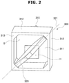
- FIG. 2 is a diagram schematically illustrating a flip-dot unit applied to the head lamp for a vehicle in accordance with the embodiment of the present disclosure
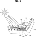
- FIG. 3 is a diagram illustrating an example of the case in which the temperature of a lamp housing applied to the head lamp for a vehicle in accordance with the embodiment of the present disclosure rises
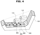
- FIG. 4 is a diagram illustrating an operation state of the flip-dot unit to lower the temperature of the lamp housing applied to the head lamp for a vehicle in accordance with the embodiment of the present disclosure
- FIG. 1 is a diagram schematically illustrating a head lamp for a vehicle in accordance with an embodiment of the present disclosure
- FIG. 2 is a diagram schematically illustrating a flip-dot unit applied to the head lamp for a vehicle in accordance with the embodiment of the present disclosure
- FIG. 3 is a diagram illustrating an example of the case in which the
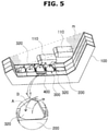
- FIG. 5 is a diagram illustrating an operation state of the flip-dot unit to lower the humidity of the lamp housing applied to the head lamp for a vehicle in accordance with the embodiment of the present disclosure
- FIG. 6 is a diagram illustrating the state in which the air of the lamp housing is circulated to remove humidity through an operation of the flip-dot unit applied to the head lamp for a vehicle in accordance with the embodiment of the present disclosure
- FIG. 7 is a diagram schematically illustrating the head lamp for a vehicle in accordance with the embodiment of the present disclosure, showing an example of the case in which the lamp housing is formed in a hemispherical shape
- FIG. 8 is a diagram illustrating an example of the case in which notice information on the state of the vehicle is displayed through the operation of the flip-dot unit applied to the head lamp for a vehicle in accordance with the embodiment of the present disclosure
- FIG. 9 is a diagram illustrating an example of the case in which notice information on the driving of a vehicle is displayed through the operation of the flip-dot unit applied to the head lamp for a vehicle in accordance with the embodiment of the present disclosure
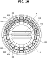
- FIG. 10 is a diagram illustrating another example of the case in which notice information on the driving of the vehicle is displayed through the operation of the flip-dot unit applied to the head lamp for a vehicle in accordance with the embodiment of the present disclosure.
- the head lamp for a vehicle in accordance with the embodiment of the present disclosure includes a lamp housing 100, a bezel 200 and a plurality of flip-dot units 300.
- the lamp housing 100 has a light source 110 installed therein, the light source 110 serving to emit light to a forward area of the vehicle.
- the bezel 200 is installed on the lamp housing 100, spaced by a predetermined distance apart from the light source 110, and disposed in a shape to cover the light source 110.
- the plurality of flip-dot units 300 are installed in the bezel 200.
- the flip-dot unit 300 includes a housing 310 and a flip disk 320.
- the housing 310 has an opening S formed on one side thereof and a space formed therein, and the flip disk 320 is rotatably installed in the housing 310 so as to open or close the opening S.
- the housing 310 of the flip-dot unit 300 is formed in an approximately rectangular parallelepiped shape as a whole, and has the opening S formed on one side thereof and the space formed therein. When the opening S is closed by the flip disk 320, the housing 310 has a rectangular parallelepiped shape.
- the housing 310 of the flip-dot unit 300 includes a first side portion 311, a second side portion 312 and a third side portion 313.
- the first side portion 311 is formed in a plate shape with an air flow hole H which communicates with the opening S, the second side portion 312 is bent and extended from the first side portion 311 so as to form the space with the first side portion 311, and the third side portion 313 is bent and extended from the second side portion 312, disposed to face the first side portion 311, and having the flip disk 320 installed thereon.
- an air flow duct (not illustrated) may be installed to communicate with the air flow hole H formed in the first side portion 311.
- the air flow duct may have an opening/closing member (not illustrated) installed to open/close the air flow duct.
- the opening/closing member may be operated to close or open the air flow duct according to the operation of the flip disk 320 to close or open the opening S.
- the plurality of flip-dot units 300 may be installed in the bezel 200 of the head lamp for a vehicle in accordance with the embodiment of the present disclosure. Furthermore, a sensor unit 400 for measuring the internal temperature and humidity of the lamp housing 100 may be installed in the bezel 200.
- the head lamp for a vehicle in accordance with the embodiment of the present disclosure may further include a control unit 500 configured to transmit a flip disk operation signal to the flip-dot unit 300 to rotate the flip disk 320.
- the flip-dot unit 300 may rotate the flip disk 320 installed therein, in order to prevent overheat and humidity in the lamp housing 100.
- each of the flip-dot units 300 may serve as a pixel of a general display device, and visualize and display notice information on the state of the vehicle or notice information related to the driving of the vehicle as figures, characters or signs, thereby calling an oncoming vehicle or pedestrian's attention.
- the notice information on the state of the vehicle is information displayed by visualizing information on whether the vehicle is turned on/off, whether the vehicle is being stopped or traveling, or whether the vehicle is in an autonomous driving mode, and the notice information related to the driving of the vehicle is information displayed by visualizing the acceleration, deceleration or turn of the vehicle.
- the flip disk 320 is referred to as a flip dot, formed in a polygonal or circular plate shape, and rotatably installed in the third side portion 313 of the housing 310 to open or close the opening S formed in the third side portion 313 of the housing 310.
- the flip disk 320 has one surface and the other surface which have different colors, and is rotated to invert the color of the flip disk 320 which appears through the bezel 200.
- the flip disk 320 may be rotated by an electromagnetic actuator (not illustrated), and the opening degree of the opening S may be changed according to the rotation angle of the flip disk 320, such that the amount of air circulated through the opening S is changed.
- the flip disk 320 is installed to rotate about a rotation axis 321 passing through the center of the third side portion, and has a symmetrical shape with respect to the rotation axis 321. Therefore, the flip disk 320 is configured in such a manner that portions disposed on both sides of the rotation axis 321 have the same shape and cross-sectional area.
- the control unit 500 may transmit a flip disk operation signal to the flip-dot unit 300 to rotate and invert the flip disk 320. This process may lower the internal temperature of the lamp housing 100 overheated by direct sunlight or the like.
- control unit 500 may transmit the flip disk operation signal to the flip-dot unit 300 to repeatedly rotate the flip disk 320. This process may circulate the air inside the lamp housing 100, thereby removing the humidity of the lamp housing 100.
- control unit 500 may transmit the flip disk operation signal to the flip-dot unit 300 to display a character or sign which can warn an oncoming vehicle or pedestrian.
- the notice information on the state of the vehicle or the notice information related to the driving of the vehicle may be effectively transferred to an oncoming vehicle or pedestrian, which makes it possible to improve a traffic flow and to prevent an accident.
- FIG. 3 is a diagram illustrating an example of the case in which the temperature of the lamp housing applied to the head lamp for a vehicle in accordance with the embodiment of the present disclosure rises
- FIG. 4 is a diagram illustrating an operation state of the flip-dot unit to lower the temperature of the lamp housing applied to the head lamp for a vehicle in accordance with the embodiment of the present disclosure.
- the internal temperature of the lamp housing 100 may be excessively raised by direct sunlight.
- the temperature of the bezel 200 inside the lamp housing 100 which is directly exposed to direct sunlight, may rapidly rise.
- control unit 500 may control the operation of the flip-dot unit 300 according to the temperature information measured by the sensor unit 400 installed in the bezel 200.
- the control unit 500 may rotate the flip disks 320 in the state illustrated in FIG. 3 , such that the heated surfaces of the flip disks 320 are turned to face the inside of the bezel 200, and the opposite surfaces of the flip disks 320, which are not heated, are turned to appear through the bezel 200, as illustrated in FIG. 4 . Then, the internal temperature of the lamp housing 100 may be lowered.
- FIG. 5 is a diagram illustrating an operation state of the flip-dot unit to lower the humidity of the lamp housing applied to the head lamp for a vehicle in accordance with the embodiment of the present disclosure
- FIG. 6 is a diagram illustrating that the air of the lamp housing is circulated to remove humidity according to the operation of the flip-dot unit applied to the head lamp for a vehicle in accordance with the embodiment of the present disclosure.
- moisture m may be generated in the lamp housing 100 by a temperature difference between the outside and the inside of the lamp housing 100.
- control unit 500 may control the operation of the flip-dot unit 300 according to the humidity measured by the sensor unit 400 installed in the bezel 200.
- the control unit 500 may operate the flip disk 320 to repeatedly rotate as illustrated in FIG. 5 . Then, as illustrated in FIG. 6 , the air inside the lamp housing 100 may be circulated (e.g. circulation indicated by an arrow C), thereby removing the moisture generated in the lamp housing 100.
- the air inside the lamp housing 100 is circulated, the air inside the lamp housing 100 and the air outside the lamp housing 100 may be exchanged.
- the air inside the lamp housing 100 and the air outside the lamp housing 100 may be exchanged through the opening S and the air flow hole H which are formed in the housing 310 of the flip-dot unit 300.
- FIG. 7 is a diagram schematically illustrating the head lamp for a vehicle in accordance with the embodiment of the present disclosure, showing an example of the case in which the lamp housing is formed in a semispherical shape.
- the function of displaying the notice information on the state of the vehicle or the notice information related to the driving of the vehicle may be exhibited more effectively than when the lamp housing 100 has the shape illustrated in FIG. 1 .
- the flip-dot units 300 may be arranged in a circular shape along the bezel 200.
- the flip-dot units 300 may be arranged in two or more lines in order to display various pieces of notice information.
- the flip disks 320 of the flip-dot units 300 may be rotated to prevent overheat and moisture in the lamp housing 100, as described above.
- FIG. 8 is a diagram illustrating an example of how the notice information on the state of the vehicle may be displayed through the head lamp for a vehicle in accordance with the embodiment of the present disclosure.
- the flip disks 320 of the flip-dot units 300 may be operated to generate a flow (i.e. a flow indicated by an arrow D) from the edge of the lamp housing 10 to the center of the lamp housing 100 where the light source 110 is located, as illustrated in FIG. 8 .
- the flip-dot unit 300 may inform an oncoming vehicle or pedestrian that the vehicle is turned on.
- FIG. 9 is a diagram illustrating an example of how the notice information related to the driving of the vehicle may be displayed through the head lamp for a vehicle in accordance with the embodiment of the present disclosure.
- the entire flip disks 320 of the flip-dot units 300 may be repeatedly operated so that the surfaces of the flip disks 320 having the same color appear, thereby informing an oncoming vehicle or pedestrian that the vehicle is in the autonomous driving mode, as illustrated in FIG. 9 .
- FIG. 10 is a diagram illustrating another example of how the notice information related to the driving of the vehicle may be displayed through the head lamp for a vehicle in accordance with the embodiment of the present disclosure.
- the flip disks 320 of the flip-dot units 300 may be operated to generate a flow in which the flip disks 320 are sequentially rotated along an arrow E, as illustrated in FIG, 10 , thereby informing an oncoming vehicle or pedestrian of the vehicle's turn.
- the flip-dot unit may be installed in the lamp housing to prevent overheat and moisture in the lamp housing, and effectively transfer the notice information on the state of the vehicle or the notice information related to the driving of the vehicle to an oncoming vehicle or pedestrian.
Landscapes
- Engineering & Computer Science (AREA)
- General Engineering & Computer Science (AREA)
- Physics & Mathematics (AREA)
- General Physics & Mathematics (AREA)
- Theoretical Computer Science (AREA)
- Business, Economics & Management (AREA)
- Accounting & Taxation (AREA)
- Marketing (AREA)
- Lighting Device Outwards From Vehicle And Optical Signal (AREA)
- Mechanical Engineering (AREA)
Abstract
Description
- Exemplary embodiments of the present disclosure relate to a head lamp for a vehicle, and more particularly, to a head lamp for a vehicle, which includes a flip-dot unit installed in a lamp housing in order to prevent overheat and moisture in the lamp housing and to effectively inform an oncoming vehicle or pedestrian of notice information on the state of a vehicle or notice information related to the driving of the vehicle.
- In general, when a vehicle travels on the road through a tunnel or in the nighttime, a head lamp of the vehicle emits light to the forward area of the vehicle such that a driver can easily check and identify an object ahead of vehicle. The head lamp is typically installed on either side of the front of the vehicle.
- The head lamp of the vehicle uses two light sources to adjust the brightness of light, when illuminating the forward area of the vehicle. Any one of the light sources is used as a low beam capable of illuminating an area at a relatively small distance, and the other of the light sources is used as a high beam capable of illustrating an area at a relatively large distance.
- In such a head lamp for a vehicle, an incandescent lamp or halogen lamp is typically used as the light source for emitting light. Recently, the case in which an LED having low power consumption and excellent light straightness is used as a light source is increasing.
- According to the recent trend in which a head lamp for a vehicle is designed to have a small size, a lamp housing may lack in an air flow space. In this case, the humidity inside the lamp housing may be increased to cause condensation.
- Furthermore, when the head lamp for a vehicle is exposed to sunlight for a long time, the surface of a bezel part of the lamp housing may be corrupted or deformed as the temperature of the bezel part increases.
- With the recent development of autonomous driving technology, technologies related to full-scale driving of autonomous vehicles are being developed. Furthermore, research is being conducted on an apparatus and method capable of effectively transferring notice information on the state of an autonomous vehicle or notice information related to the driving of the autonomous vehicle to an oncoming vehicle or pedestrian, among the technologies related to autonomous vehicles. Besides, there is a need for developing an apparatus and method which can display notice information related to an autonomous vehicle to the outside of the vehicle more effectively with lower power consumption, and minimize damage to a pedestrian.
- The related art of the present disclosure is disclosed in
Korean Patent No. 10-1487904 registered on January 23, 2015 - Various embodiments are directed to a head lamp for a vehicle, which includes a flip-dot unit installed in a lamp housing in order to prevent overheat and moisture in the lamp housing and to effectively inform an oncoming vehicle or pedestrian of notice information on the state of a vehicle or notice information related to the driving of the vehicle.
- In an embodiment, a head lamp for a vehicle may include: a lamp housing having a light source installed therein, the light source serving to emit light to a forward area of a vehicle; a bezel installed on the lamp housing, spaced by a predetermined distance apart from the light source, and disposed in a shape to cover the light source; and a plurality of flip-dot units installed in the bezel. Each of the flip dot units may include: a housing having an opening formed on one side thereof and a space formed therein; and a flip disk rotatably installed in the housing so as to open or close the opening.
- The housing may include: a first side portion formed in a plate shape, and having an air flow hole to communicate with the opening; a second side portion bent and extended from the first side portion, and configured to form the space with the first side portion; and a third side portion bent and extended from the second side portion, disposed to face the first side portion, and having the flip disk installed thereon.
- The flip disk may be installed to rotate about a rotation axis passing through a center of the third side portion.
- The flip disk may have a symmetrical shape with respect to a center axis.
- The head lamp may further include: a sensor unit installed in the bezel and configured to measure an internal temperature and humidity of the lamp housing; and a control unit configured to transmit a flip disk operation signal to the flip-dot unit to rotate the flip disk.
- The control unit may transmit a flip disk operation signal to the flip-dot unit to rotate and invert the flip disk according to the internal temperature of the lamp housing, measured by the sensor unit.
- The control unit may transmit a flip disk operation signal to the flip-dot unit to repeatedly rotate the flip disk according to the internal humidity of the lamp housing, measured by the sensor unit.
- The control unit may transmit a flip disk operation signal to the flip-dot unit to display a character or sign for warning an oncoming vehicle or pedestrian.
- In the head lamp for a vehicle in accordance with the embodiment of the present disclosure, the flip-dot unit may be installed in the lamp housing to prevent overheat and moisture in the lamp housing.
- In the head lamp for a vehicle in accordance with the embodiment of the present disclosure, the flip-dot unit may be installed in the lamp housing to effectively transfer the notice information on the state of the vehicle or the notice information related to the driving of the vehicle to an oncoming vehicle or pedestrian.
-
-
FIG. 1 is a diagram schematically illustrating a head lamp for a vehicle in accordance with an embodiment of the present disclosure. -
FIG. 2 is a diagram schematically illustrating a flip-dot unit applied to the head lamp for a vehicle in accordance with the embodiment of the present disclosure. -
FIG. 3 is a diagram illustrating an example of the case in which the temperature of a lamp housing applied to the head lamp for a vehicle in accordance with the embodiment of the present disclosure rises. -
FIG. 4 is a diagram illustrating an operation state of the flip-dot unit to lower the temperature of the lamp housing applied to the head lamp for a vehicle in accordance with the embodiment of the present disclosure. -
FIG. 5 is a diagram illustrating an operation state of the flip-dot unit to lower the humidity of the lamp housing applied to the head lamp for a vehicle in accordance with the embodiment of the present disclosure. -
FIG. 6 is a diagram illustrating the state in which the air of the lamp housing is circulated to remove humidity through an operation of the flip-dot unit applied to the head lamp for a vehicle in accordance with the embodiment of the present disclosure. -
FIG. 7 is a diagram schematically illustrating the head lamp for a vehicle in accordance with the embodiment of the present disclosure, showing an example of the case in which the lamp housing is formed in a hemispherical shape. -
FIG. 8 is a diagram illustrating an example of the case in which notice information on the state of the vehicle is displayed through the operation of the flip-dot unit applied to the head lamp for a vehicle in accordance with the embodiment of the present disclosure. -
FIG. 9 is a diagram illustrating an example of the case in which notice information on the driving of a vehicle is displayed through the operation of the flip-dot unit applied to the head lamp for a vehicle in accordance with the embodiment of the present disclosure. -
FIG. 10 is a diagram illustrating another example of the case in which notice information on the driving of the vehicle is displayed through the operation of the flip-dot unit applied to the head lamp for a vehicle in accordance with the embodiment of the present disclosure. - Hereinafter, a head lamp for a vehicle will be described below with reference to the accompanying drawings through various exemplary embodiments. It should be noted that the drawings are not to precise scale and may be exaggerated in thickness of lines or sizes of components for descriptive convenience and clarity only. Furthermore, the terms as used herein are defined by taking functions of the invention into account and can be changed according to the custom or intention of users or operators. Therefore, definition of the terms should be made according to the overall disclosures set forth herein.
-
FIG. 1 is a diagram schematically illustrating a head lamp for a vehicle in accordance with an embodiment of the present disclosure,FIG. 2 is a diagram schematically illustrating a flip-dot unit applied to the head lamp for a vehicle in accordance with the embodiment of the present disclosure,FIG. 3 is a diagram illustrating an example of the case in which the temperature of a lamp housing applied to the head lamp for a vehicle in accordance with the embodiment of the present disclosure rises,FIG. 4 is a diagram illustrating an operation state of the flip-dot unit to lower the temperature of the lamp housing applied to the head lamp for a vehicle in accordance with the embodiment of the present disclosure,FIG. 5 is a diagram illustrating an operation state of the flip-dot unit to lower the humidity of the lamp housing applied to the head lamp for a vehicle in accordance with the embodiment of the present disclosure,FIG. 6 is a diagram illustrating the state in which the air of the lamp housing is circulated to remove humidity through an operation of the flip-dot unit applied to the head lamp for a vehicle in accordance with the embodiment of the present disclosure,FIG. 7 is a diagram schematically illustrating the head lamp for a vehicle in accordance with the embodiment of the present disclosure, showing an example of the case in which the lamp housing is formed in a hemispherical shape,FIG. 8 is a diagram illustrating an example of the case in which notice information on the state of the vehicle is displayed through the operation of the flip-dot unit applied to the head lamp for a vehicle in accordance with the embodiment of the present disclosure,FIG. 9 is a diagram illustrating an example of the case in which notice information on the driving of a vehicle is displayed through the operation of the flip-dot unit applied to the head lamp for a vehicle in accordance with the embodiment of the present disclosure, andFIG. 10 is a diagram illustrating another example of the case in which notice information on the driving of the vehicle is displayed through the operation of the flip-dot unit applied to the head lamp for a vehicle in accordance with the embodiment of the present disclosure. - Referring to
FIGS. 1 to 10 , the head lamp for a vehicle in accordance with the embodiment of the present disclosure includes alamp housing 100, abezel 200 and a plurality of flip-dot units 300. Thelamp housing 100 has alight source 110 installed therein, thelight source 110 serving to emit light to a forward area of the vehicle. Thebezel 200 is installed on thelamp housing 100, spaced by a predetermined distance apart from thelight source 110, and disposed in a shape to cover thelight source 110. The plurality of flip-dot units 300 are installed in thebezel 200. - As illustrated in
FIG. 2 , the flip-dot unit 300 includes ahousing 310 and aflip disk 320. Thehousing 310 has an opening S formed on one side thereof and a space formed therein, and theflip disk 320 is rotatably installed in thehousing 310 so as to open or close the opening S. - The
housing 310 of the flip-dot unit 300 is formed in an approximately rectangular parallelepiped shape as a whole, and has the opening S formed on one side thereof and the space formed therein. When the opening S is closed by theflip disk 320, thehousing 310 has a rectangular parallelepiped shape. - The
housing 310 of the flip-dot unit 300 includes afirst side portion 311, asecond side portion 312 and athird side portion 313. Thefirst side portion 311 is formed in a plate shape with an air flow hole H which communicates with the opening S, thesecond side portion 312 is bent and extended from thefirst side portion 311 so as to form the space with thefirst side portion 311, and thethird side portion 313 is bent and extended from thesecond side portion 312, disposed to face thefirst side portion 311, and having theflip disk 320 installed thereon. - Outside the
housing 310, an air flow duct (not illustrated) may be installed to communicate with the air flow hole H formed in thefirst side portion 311. The air flow duct may have an opening/closing member (not illustrated) installed to open/close the air flow duct. The opening/closing member may be operated to close or open the air flow duct according to the operation of theflip disk 320 to close or open the opening S. - The plurality of flip-
dot units 300 may be installed in thebezel 200 of the head lamp for a vehicle in accordance with the embodiment of the present disclosure. Furthermore, asensor unit 400 for measuring the internal temperature and humidity of thelamp housing 100 may be installed in thebezel 200. - Furthermore, the head lamp for a vehicle in accordance with the embodiment of the present disclosure may further include a
control unit 500 configured to transmit a flip disk operation signal to the flip-dot unit 300 to rotate theflip disk 320. - The flip-
dot unit 300 may rotate theflip disk 320 installed therein, in order to prevent overheat and humidity in thelamp housing 100. - Furthermore, each of the flip-
dot units 300 may serve as a pixel of a general display device, and visualize and display notice information on the state of the vehicle or notice information related to the driving of the vehicle as figures, characters or signs, thereby calling an oncoming vehicle or pedestrian's attention. - The notice information on the state of the vehicle is information displayed by visualizing information on whether the vehicle is turned on/off, whether the vehicle is being stopped or traveling, or whether the vehicle is in an autonomous driving mode, and the notice information related to the driving of the vehicle is information displayed by visualizing the acceleration, deceleration or turn of the vehicle.
- The
flip disk 320 is referred to as a flip dot, formed in a polygonal or circular plate shape, and rotatably installed in thethird side portion 313 of thehousing 310 to open or close the opening S formed in thethird side portion 313 of thehousing 310. - The
flip disk 320 has one surface and the other surface which have different colors, and is rotated to invert the color of theflip disk 320 which appears through thebezel 200. - The
flip disk 320 may be rotated by an electromagnetic actuator (not illustrated), and the opening degree of the opening S may be changed according to the rotation angle of theflip disk 320, such that the amount of air circulated through the opening S is changed. - The
flip disk 320 is installed to rotate about arotation axis 321 passing through the center of the third side portion, and has a symmetrical shape with respect to therotation axis 321. Therefore, theflip disk 320 is configured in such a manner that portions disposed on both sides of therotation axis 321 have the same shape and cross-sectional area. - When the internal temperature of the
lamp housing 100, measured by thesensor unit 400, is equal to or higher than a preset value, thecontrol unit 500 may transmit a flip disk operation signal to the flip-dot unit 300 to rotate and invert theflip disk 320. This process may lower the internal temperature of thelamp housing 100 overheated by direct sunlight or the like. - Furthermore, when the internal humidity of the
lamp housing 100, measured by thesensor unit 400, is equal to or higher than a preset value, thecontrol unit 500 may transmit the flip disk operation signal to the flip-dot unit 300 to repeatedly rotate theflip disk 320. This process may circulate the air inside thelamp housing 100, thereby removing the humidity of thelamp housing 100. - Furthermore, the
control unit 500 may transmit the flip disk operation signal to the flip-dot unit 300 to display a character or sign which can warn an oncoming vehicle or pedestrian. Through this process, the notice information on the state of the vehicle or the notice information related to the driving of the vehicle may be effectively transferred to an oncoming vehicle or pedestrian, which makes it possible to improve a traffic flow and to prevent an accident. - Hereafter, the operation of the head lamp for a vehicle in accordance with the embodiment of the present disclosure will be described in detail.
- Referring to
FIGS. 3 to 4 , an overheat prevention function of the head lamp for a vehicle in accordance with the embodiment of the present disclosure will be described as follows. -
FIG. 3 is a diagram illustrating an example of the case in which the temperature of the lamp housing applied to the head lamp for a vehicle in accordance with the embodiment of the present disclosure rises, andFIG. 4 is a diagram illustrating an operation state of the flip-dot unit to lower the temperature of the lamp housing applied to the head lamp for a vehicle in accordance with the embodiment of the present disclosure. - As illustrated in
FIG. 3 , the internal temperature of thelamp housing 100 may be excessively raised by direct sunlight. In particular, the temperature of thebezel 200 inside thelamp housing 100, which is directly exposed to direct sunlight, may rapidly rise. - When the internal temperature of the
lamp housing 100 excessively rises, thecontrol unit 500 may control the operation of the flip-dot unit 300 according to the temperature information measured by thesensor unit 400 installed in thebezel 200. - That is, when the internal temperature of the
lamp housing 100 is equal to or higher than the preset value, thecontrol unit 500 may rotate theflip disks 320 in the state illustrated inFIG. 3 , such that the heated surfaces of theflip disks 320 are turned to face the inside of thebezel 200, and the opposite surfaces of theflip disks 320, which are not heated, are turned to appear through thebezel 200, as illustrated inFIG. 4 . Then, the internal temperature of thelamp housing 100 may be lowered. - Referring to
FIGS. 5 to 6 , a humidity prevention function of the head lamp for a vehicle in accordance with the embodiment of the present disclosure will be described as follows. -
FIG. 5 is a diagram illustrating an operation state of the flip-dot unit to lower the humidity of the lamp housing applied to the head lamp for a vehicle in accordance with the embodiment of the present disclosure, andFIG. 6 is a diagram illustrating that the air of the lamp housing is circulated to remove humidity according to the operation of the flip-dot unit applied to the head lamp for a vehicle in accordance with the embodiment of the present disclosure. - As illustrated in
FIG. 5 , moisture m may be generated in thelamp housing 100 by a temperature difference between the outside and the inside of thelamp housing 100. - When the moisture m is generated in the
lamp housing 100, thecontrol unit 500 may control the operation of the flip-dot unit 300 according to the humidity measured by thesensor unit 400 installed in thebezel 200. - That is, when the internal humidity of the
lamp housing 100 is equal to or higher than a preset value, thecontrol unit 500 may operate theflip disk 320 to repeatedly rotate as illustrated inFIG. 5 . Then, as illustrated inFIG. 6 , the air inside thelamp housing 100 may be circulated (e.g. circulation indicated by an arrow C), thereby removing the moisture generated in thelamp housing 100. - Furthermore, while the air inside the
lamp housing 100 is circulated, the air inside thelamp housing 100 and the air outside thelamp housing 100 may be exchanged. In this case, the air inside thelamp housing 100 and the air outside thelamp housing 100 may be exchanged through the opening S and the air flow hole H which are formed in thehousing 310 of the flip-dot unit 300. - Referring to
FIGS. 7 to 10 , the function of displaying the notice information on the state of the vehicle and the notice information related to the driving of the vehicle through the head lamp for a vehicle in accordance with the embodiment of the present disclosure will be described as follows. -
FIG. 7 is a diagram schematically illustrating the head lamp for a vehicle in accordance with the embodiment of the present disclosure, showing an example of the case in which the lamp housing is formed in a semispherical shape. - When the
lamp housing 100 has a hemispherical shape illustrated inFIG. 7 , the function of displaying the notice information on the state of the vehicle or the notice information related to the driving of the vehicle may be exhibited more effectively than when thelamp housing 100 has the shape illustrated inFIG. 1 . - When the
hemispherical lamp housing 100 is applied as illustrated inFIG. 7 , the flip-dot units 300 may be arranged in a circular shape along thebezel 200. In this case, the flip-dot units 300 may be arranged in two or more lines in order to display various pieces of notice information. - Even when the
hemispherical lamp housing 100 is applied, theflip disks 320 of the flip-dot units 300 may be rotated to prevent overheat and moisture in thelamp housing 100, as described above. -
FIG. 8 is a diagram illustrating an example of how the notice information on the state of the vehicle may be displayed through the head lamp for a vehicle in accordance with the embodiment of the present disclosure. - For example, when the vehicle is turned on, the
flip disks 320 of the flip-dot units 300 may be operated to generate a flow (i.e. a flow indicated by an arrow D) from the edge of the lamp housing 10 to the center of thelamp housing 100 where thelight source 110 is located, as illustrated inFIG. 8 . In this way, the flip-dot unit 300 may inform an oncoming vehicle or pedestrian that the vehicle is turned on. -
FIG. 9 is a diagram illustrating an example of how the notice information related to the driving of the vehicle may be displayed through the head lamp for a vehicle in accordance with the embodiment of the present disclosure. - For example, when the vehicle enters the autonomous driving mode, the
entire flip disks 320 of the flip-dot units 300 may be repeatedly operated so that the surfaces of theflip disks 320 having the same color appear, thereby informing an oncoming vehicle or pedestrian that the vehicle is in the autonomous driving mode, as illustrated inFIG. 9 . -
FIG. 10 is a diagram illustrating another example of how the notice information related to the driving of the vehicle may be displayed through the head lamp for a vehicle in accordance with the embodiment of the present disclosure. - For example, when the vehicle makes a turn, the
flip disks 320 of the flip-dot units 300 may be operated to generate a flow in which theflip disks 320 are sequentially rotated along an arrow E, as illustrated inFIG, 10 , thereby informing an oncoming vehicle or pedestrian of the vehicle's turn. - In the head lamp for a vehicle in accordance with the embodiment of the present disclosure, the flip-dot unit may be installed in the lamp housing to prevent overheat and moisture in the lamp housing, and effectively transfer the notice information on the state of the vehicle or the notice information related to the driving of the vehicle to an oncoming vehicle or pedestrian.
- Although exemplary embodiments of the disclosure have been disclosed for illustrative purposes, those skilled in the art will appreciate that various modifications, additions and substitutions are possible, without departing from the scope and spirit of the disclosure as defined in the accompanying claims. Thus, the true technical scope of the disclosure should be defined by the following claims.
Claims (8)
- A head lamp for a vehicle, comprising:a lamp housing having a light source installed therein, the light source serving to emit light to a forward area of a vehicle;a bezel installed on the lamp housing, spaced by a predetermined distance apart from the light source, and disposed in a shape to cover the light source; anda plurality of flip-dot units installed in the bezel,wherein each of the flip dot units comprises:a housing having an opening formed on one side thereof and a space formed therein; anda flip disk rotatably installed in the housing so as to open or close the opening.
- The head lamp for the vehicle of claim 1, wherein the housing comprises:a first side portion formed in a plate shape, and having an air flow hole to communicate with the opening;a second side portion bent and extended from the first side portion, and configured to form the space with the first side portion; anda third side portion bent and extended from the second side portion, disposed to face the first side portion, and having the flip disk installed thereon.
- The head lamp for the vehicle of claim 2, wherein the flip disk is installed to rotate about a rotation axis passing through a center of the third side portion.
- The head lamp for the vehicle of claim 3, wherein the flip disk has a symmetrical shape with respect to a center axis.
- The head lamp for the vehicle of claim 1, further comprising:a sensor unit installed in the bezel and configured to measure an internal temperature and humidity of the lamp housing; anda control unit configured to transmit a flip disk operation signal to the flip-dot unit to rotate the flip disk.
- The head lamp for the vehicle of claim 5, wherein the control unit transmits a flip disk operation signal to the flip-dot unit to rotate and invert the flip disk according to the internal temperature of the lamp housing, measured by the sensor unit.
- The head lamp for the vehicle of claim 5, wherein the control unit transmits a flip disk operation signal to the flip-dot unit to repeatedly rotate the flip disk according to the internal humidity of the lamp housing, measured by the sensor unit.
- The head lamp for the vehicle of claim 5, wherein the control unit transmits a flip disk operation signal to the flip-dot unit to display a character or sign for warning an oncoming vehicle or pedestrian.
Applications Claiming Priority (1)
| Application Number | Priority Date | Filing Date | Title |
|---|---|---|---|
| KR1020200094298A KR102795244B1 (en) | 2020-07-29 | 2020-07-29 | Head lamp for vehicle |
Publications (2)
| Publication Number | Publication Date |
|---|---|
| EP3945242A1 true EP3945242A1 (en) | 2022-02-02 |
| EP3945242B1 EP3945242B1 (en) | 2024-10-23 |
Family
ID=77103956
Family Applications (1)
| Application Number | Title | Priority Date | Filing Date |
|---|---|---|---|
| EP21188160.2A Active EP3945242B1 (en) | 2020-07-29 | 2021-07-28 | Head lamp for vehicle |
Country Status (4)
| Country | Link |
|---|---|
| US (1) | US11378249B2 (en) |
| EP (1) | EP3945242B1 (en) |
| KR (1) | KR102795244B1 (en) |
| CN (1) | CN114060766B (en) |
Citations (6)
| Publication number | Priority date | Publication date | Assignee | Title |
|---|---|---|---|---|
| DE202004019133U1 (en) * | 2004-10-07 | 2005-05-12 | Brunner, Armin, Ing. | Element for display panel has frame with small plates with colored fronts and black backs pivotable when activated by magnets to present either their fronts or backs, light source for illuminating plates whose fronts are visible |
| DE102012004759A1 (en) * | 2012-03-08 | 2013-09-12 | GM Global Technology Operations LLC (n.d. Ges. d. Staates Delaware) | Tail lamp arrangement of motor car, has display surface portion that is arranged with several distributed luminous elements for forming and independently controlling different light patterns |
| KR101487904B1 (en) | 2014-10-20 | 2015-02-04 | 코이안(주) | Flip Dot Display Element using Electromagnet and Assembly Module thereof |
| WO2016089926A1 (en) * | 2014-12-01 | 2016-06-09 | Ihedinmah Chukwudi | Vehicle digital message display |
| DE102016013510A1 (en) * | 2016-04-18 | 2017-10-19 | Kastriot Merlaku | Headlight system for vehicles of all kinds, with at least one light source and a camera for the road detection |
| EP3597991A1 (en) * | 2018-06-21 | 2020-01-22 | Automotive Lighting Italia S.p.A. | Automotive light |
Family Cites Families (13)
| Publication number | Priority date | Publication date | Assignee | Title |
|---|---|---|---|---|
| KR0124888Y1 (en) * | 1994-12-30 | 1998-08-17 | 전성원 | Cooler for a headlight |
| US6278431B1 (en) * | 1996-11-18 | 2001-08-21 | Lite Vision Corporation | Magnetically operated display |
| US6033099A (en) * | 1998-03-25 | 2000-03-07 | Kulis; Philip | Add-on-flip-up headlight winking system and method of winking headlights |
| US6739969B2 (en) * | 2002-07-02 | 2004-05-25 | Yundai Mobis, Co., Ltd. | Air vent provided with a cover |
| DE102007004702A1 (en) * | 2007-01-31 | 2008-08-07 | Volkswagen Ag | Vehicle light i.e. headlight, has condensation protection device, light emitting unit arranged in light housing, and electrical heating device arranged in gap formed on bottom side of light housing, where device heats air in gap |
| US7789541B2 (en) * | 2008-03-31 | 2010-09-07 | Tokyo Electron Limited | Method and system for lamp temperature control in optical metrology |
| KR20150059497A (en) * | 2013-11-22 | 2015-06-01 | 현대모비스 주식회사 | Head lamp for vehicle |
| KR101728997B1 (en) * | 2015-10-07 | 2017-04-21 | 현대모비스 주식회사 | Ventilation of lamp module for vehicles |
| KR20170070704A (en) * | 2015-12-14 | 2017-06-22 | 르노삼성자동차 주식회사 | Headlamp for vehicle |
| JP6823371B2 (en) * | 2015-12-17 | 2021-02-03 | 日東電工株式会社 | Ventilation and humidity control unit and equipment |
| KR20170101593A (en) * | 2016-02-29 | 2017-09-06 | 엘지전자 주식회사 | Apparatus for driving headlamp of vehicle and vehicle including the same |
| US10730427B2 (en) * | 2016-12-28 | 2020-08-04 | Koito Manufacturing Co., Ltd. | Lighting device |
| JP7233187B2 (en) * | 2018-09-19 | 2023-03-06 | 株式会社小糸製作所 | vehicle lamp |
-
2020
- 2020-07-29 KR KR1020200094298A patent/KR102795244B1/en active Active
-
2021
- 2021-07-28 US US17/386,926 patent/US11378249B2/en active Active
- 2021-07-28 EP EP21188160.2A patent/EP3945242B1/en active Active
- 2021-07-29 CN CN202110863462.6A patent/CN114060766B/en active Active
Patent Citations (6)
| Publication number | Priority date | Publication date | Assignee | Title |
|---|---|---|---|---|
| DE202004019133U1 (en) * | 2004-10-07 | 2005-05-12 | Brunner, Armin, Ing. | Element for display panel has frame with small plates with colored fronts and black backs pivotable when activated by magnets to present either their fronts or backs, light source for illuminating plates whose fronts are visible |
| DE102012004759A1 (en) * | 2012-03-08 | 2013-09-12 | GM Global Technology Operations LLC (n.d. Ges. d. Staates Delaware) | Tail lamp arrangement of motor car, has display surface portion that is arranged with several distributed luminous elements for forming and independently controlling different light patterns |
| KR101487904B1 (en) | 2014-10-20 | 2015-02-04 | 코이안(주) | Flip Dot Display Element using Electromagnet and Assembly Module thereof |
| WO2016089926A1 (en) * | 2014-12-01 | 2016-06-09 | Ihedinmah Chukwudi | Vehicle digital message display |
| DE102016013510A1 (en) * | 2016-04-18 | 2017-10-19 | Kastriot Merlaku | Headlight system for vehicles of all kinds, with at least one light source and a camera for the road detection |
| EP3597991A1 (en) * | 2018-06-21 | 2020-01-22 | Automotive Lighting Italia S.p.A. | Automotive light |
Also Published As
| Publication number | Publication date |
|---|---|
| KR102795244B1 (en) | 2025-04-15 |
| EP3945242B1 (en) | 2024-10-23 |
| US11378249B2 (en) | 2022-07-05 |
| US20220034474A1 (en) | 2022-02-03 |
| CN114060766B (en) | 2024-05-31 |
| CN114060766A (en) | 2022-02-18 |
| KR20220014558A (en) | 2022-02-07 |
Similar Documents
| Publication | Publication Date | Title |
|---|---|---|
| US11651713B2 (en) | Flip dot display apparatus for vehicle | |
| US6646810B2 (en) | Display backlighting apparatus | |
| CN115371016A (en) | Lighting device for vehicle | |
| KR20170133331A (en) | Optical Sensing Head Up Display with Reflective Mode and Radial Mode | |
| CN103207453A (en) | Head-up display, vehicle and control method for head-up display | |
| US5917666A (en) | Rear view mirror having trailing distance indicia | |
| CN110121444B (en) | Lighting device | |
| CN114056228A (en) | Vehicle information display device and control method thereof | |
| KR101446063B1 (en) | Variable information Sign | |
| US11378249B2 (en) | Head lamp for vehicle | |
| US11772543B2 (en) | Lighting apparatus for vehicle and control method thereof | |
| JP7658387B2 (en) | Notification Device | |
| KR102196308B1 (en) | School-zone light panel device and system | |
| JP2019059387A (en) | Lighting system and moving body | |
| US5500652A (en) | Display element with reflective lens | |
| JP6597230B2 (en) | Display device | |
| KR20230155229A (en) | Variable frort display grill for vehicle | |
| JP5728698B2 (en) | Automotive electronics | |
| JP2004226364A (en) | Display device for vehicles | |
| KR101753122B1 (en) | Variable information Sign | |
| KR102616507B1 (en) | Inner bumper projection system for automabiles using unit solid state surface light source and meta-mirror(multi-mirror cells) | |
| US12203641B2 (en) | Vehicle interior panel | |
| KR200353973Y1 (en) | The side-mirror which has a luminous function | |
| CN121206410A (en) | Lighting fixtures for door entrances and related vehicle bodies. | |
| JPH08221692A (en) | Signal light |
Legal Events
| Date | Code | Title | Description |
|---|---|---|---|
| PUAI | Public reference made under article 153(3) epc to a published international application that has entered the european phase |
Free format text: ORIGINAL CODE: 0009012 |
|
| STAA | Information on the status of an ep patent application or granted ep patent |
Free format text: STATUS: REQUEST FOR EXAMINATION WAS MADE |
|
| 17P | Request for examination filed |
Effective date: 20210728 |
|
| AK | Designated contracting states |
Kind code of ref document: A1 Designated state(s): AL AT BE BG CH CY CZ DE DK EE ES FI FR GB GR HR HU IE IS IT LI LT LU LV MC MK MT NL NO PL PT RO RS SE SI SK SM TR |
|
| RBV | Designated contracting states (corrected) |
Designated state(s): AL AT BE BG CH CY CZ DE DK EE ES FI FR GB GR HR HU IE IS IT LI LT LU LV MC MK MT NL NO PL PT RO RS SE SI SK SM TR |
|
| GRAP | Despatch of communication of intention to grant a patent |
Free format text: ORIGINAL CODE: EPIDOSNIGR1 |
|
| STAA | Information on the status of an ep patent application or granted ep patent |
Free format text: STATUS: GRANT OF PATENT IS INTENDED |
|
| RIC1 | Information provided on ipc code assigned before grant |
Ipc: G09F 21/04 20060101ALI20240621BHEP Ipc: G09F 9/37 20060101ALI20240621BHEP Ipc: F21S 45/33 20180101ALI20240621BHEP Ipc: F21S 41/50 20180101ALI20240621BHEP Ipc: F21S 45/20 20180101ALI20240621BHEP Ipc: F21S 45/10 20180101AFI20240621BHEP |
|
| INTG | Intention to grant announced |
Effective date: 20240708 |
|
| GRAS | Grant fee paid |
Free format text: ORIGINAL CODE: EPIDOSNIGR3 |
|
| P01 | Opt-out of the competence of the unified patent court (upc) registered |
Free format text: CASE NUMBER: APP_46685/2024 Effective date: 20240812 |
|
| GRAA | (expected) grant |
Free format text: ORIGINAL CODE: 0009210 |
|
| STAA | Information on the status of an ep patent application or granted ep patent |
Free format text: STATUS: THE PATENT HAS BEEN GRANTED |
|
| AK | Designated contracting states |
Kind code of ref document: B1 Designated state(s): AL AT BE BG CH CY CZ DE DK EE ES FI FR GB GR HR HU IE IS IT LI LT LU LV MC MK MT NL NO PL PT RO RS SE SI SK SM TR |
|
| REG | Reference to a national code |
Ref country code: GB Ref legal event code: FG4D |
|
| REG | Reference to a national code |
Ref country code: CH Ref legal event code: EP |
|
| REG | Reference to a national code |
Ref country code: DE Ref legal event code: R096 Ref document number: 602021020560 Country of ref document: DE |
|
| REG | Reference to a national code |
Ref country code: IE Ref legal event code: FG4D |
|
| REG | Reference to a national code |
Ref country code: LT Ref legal event code: MG9D |
|
| REG | Reference to a national code |
Ref country code: NL Ref legal event code: MP Effective date: 20241023 |
|
| REG | Reference to a national code |
Ref country code: AT Ref legal event code: MK05 Ref document number: 1735105 Country of ref document: AT Kind code of ref document: T Effective date: 20241023 |
|
| PG25 | Lapsed in a contracting state [announced via postgrant information from national office to epo] |
Ref country code: NL Free format text: LAPSE BECAUSE OF FAILURE TO SUBMIT A TRANSLATION OF THE DESCRIPTION OR TO PAY THE FEE WITHIN THE PRESCRIBED TIME-LIMIT Effective date: 20241023 |
|
| PG25 | Lapsed in a contracting state [announced via postgrant information from national office to epo] |
Ref country code: NL Free format text: LAPSE BECAUSE OF FAILURE TO SUBMIT A TRANSLATION OF THE DESCRIPTION OR TO PAY THE FEE WITHIN THE PRESCRIBED TIME-LIMIT Effective date: 20241023 |
|
| PG25 | Lapsed in a contracting state [announced via postgrant information from national office to epo] |
Ref country code: PT Free format text: LAPSE BECAUSE OF FAILURE TO SUBMIT A TRANSLATION OF THE DESCRIPTION OR TO PAY THE FEE WITHIN THE PRESCRIBED TIME-LIMIT Effective date: 20250224 Ref country code: IS Free format text: LAPSE BECAUSE OF FAILURE TO SUBMIT A TRANSLATION OF THE DESCRIPTION OR TO PAY THE FEE WITHIN THE PRESCRIBED TIME-LIMIT Effective date: 20250223 Ref country code: HR Free format text: LAPSE BECAUSE OF FAILURE TO SUBMIT A TRANSLATION OF THE DESCRIPTION OR TO PAY THE FEE WITHIN THE PRESCRIBED TIME-LIMIT Effective date: 20241023 |
|
| PG25 | Lapsed in a contracting state [announced via postgrant information from national office to epo] |
Ref country code: FI Free format text: LAPSE BECAUSE OF FAILURE TO SUBMIT A TRANSLATION OF THE DESCRIPTION OR TO PAY THE FEE WITHIN THE PRESCRIBED TIME-LIMIT Effective date: 20241023 |
|
| PG25 | Lapsed in a contracting state [announced via postgrant information from national office to epo] |
Ref country code: BG Free format text: LAPSE BECAUSE OF FAILURE TO SUBMIT A TRANSLATION OF THE DESCRIPTION OR TO PAY THE FEE WITHIN THE PRESCRIBED TIME-LIMIT Effective date: 20241023 |
|
| PG25 | Lapsed in a contracting state [announced via postgrant information from national office to epo] |
Ref country code: ES Free format text: LAPSE BECAUSE OF FAILURE TO SUBMIT A TRANSLATION OF THE DESCRIPTION OR TO PAY THE FEE WITHIN THE PRESCRIBED TIME-LIMIT Effective date: 20241023 |
|
| PG25 | Lapsed in a contracting state [announced via postgrant information from national office to epo] |
Ref country code: NO Free format text: LAPSE BECAUSE OF FAILURE TO SUBMIT A TRANSLATION OF THE DESCRIPTION OR TO PAY THE FEE WITHIN THE PRESCRIBED TIME-LIMIT Effective date: 20250123 |
|
| PG25 | Lapsed in a contracting state [announced via postgrant information from national office to epo] |
Ref country code: LV Free format text: LAPSE BECAUSE OF FAILURE TO SUBMIT A TRANSLATION OF THE DESCRIPTION OR TO PAY THE FEE WITHIN THE PRESCRIBED TIME-LIMIT Effective date: 20241023 Ref country code: GR Free format text: LAPSE BECAUSE OF FAILURE TO SUBMIT A TRANSLATION OF THE DESCRIPTION OR TO PAY THE FEE WITHIN THE PRESCRIBED TIME-LIMIT Effective date: 20250124 Ref country code: AT Free format text: LAPSE BECAUSE OF FAILURE TO SUBMIT A TRANSLATION OF THE DESCRIPTION OR TO PAY THE FEE WITHIN THE PRESCRIBED TIME-LIMIT Effective date: 20241023 |
|
| PG25 | Lapsed in a contracting state [announced via postgrant information from national office to epo] |
Ref country code: PL Free format text: LAPSE BECAUSE OF FAILURE TO SUBMIT A TRANSLATION OF THE DESCRIPTION OR TO PAY THE FEE WITHIN THE PRESCRIBED TIME-LIMIT Effective date: 20241023 |
|
| PG25 | Lapsed in a contracting state [announced via postgrant information from national office to epo] |
Ref country code: RS Free format text: LAPSE BECAUSE OF FAILURE TO SUBMIT A TRANSLATION OF THE DESCRIPTION OR TO PAY THE FEE WITHIN THE PRESCRIBED TIME-LIMIT Effective date: 20250123 |
|
| PG25 | Lapsed in a contracting state [announced via postgrant information from national office to epo] |
Ref country code: SM Free format text: LAPSE BECAUSE OF FAILURE TO SUBMIT A TRANSLATION OF THE DESCRIPTION OR TO PAY THE FEE WITHIN THE PRESCRIBED TIME-LIMIT Effective date: 20241023 |
|
| PG25 | Lapsed in a contracting state [announced via postgrant information from national office to epo] |
Ref country code: DK Free format text: LAPSE BECAUSE OF FAILURE TO SUBMIT A TRANSLATION OF THE DESCRIPTION OR TO PAY THE FEE WITHIN THE PRESCRIBED TIME-LIMIT Effective date: 20241023 |
|
| PG25 | Lapsed in a contracting state [announced via postgrant information from national office to epo] |
Ref country code: EE Free format text: LAPSE BECAUSE OF FAILURE TO SUBMIT A TRANSLATION OF THE DESCRIPTION OR TO PAY THE FEE WITHIN THE PRESCRIBED TIME-LIMIT Effective date: 20241023 |
|
| PG25 | Lapsed in a contracting state [announced via postgrant information from national office to epo] |
Ref country code: RO Free format text: LAPSE BECAUSE OF FAILURE TO SUBMIT A TRANSLATION OF THE DESCRIPTION OR TO PAY THE FEE WITHIN THE PRESCRIBED TIME-LIMIT Effective date: 20241023 |
|
| REG | Reference to a national code |
Ref country code: DE Ref legal event code: R097 Ref document number: 602021020560 Country of ref document: DE |
|
| PG25 | Lapsed in a contracting state [announced via postgrant information from national office to epo] |
Ref country code: SK Free format text: LAPSE BECAUSE OF FAILURE TO SUBMIT A TRANSLATION OF THE DESCRIPTION OR TO PAY THE FEE WITHIN THE PRESCRIBED TIME-LIMIT Effective date: 20241023 |
|
| PG25 | Lapsed in a contracting state [announced via postgrant information from national office to epo] |
Ref country code: CZ Free format text: LAPSE BECAUSE OF FAILURE TO SUBMIT A TRANSLATION OF THE DESCRIPTION OR TO PAY THE FEE WITHIN THE PRESCRIBED TIME-LIMIT Effective date: 20241023 |
|
| PG25 | Lapsed in a contracting state [announced via postgrant information from national office to epo] |
Ref country code: IT Free format text: LAPSE BECAUSE OF FAILURE TO SUBMIT A TRANSLATION OF THE DESCRIPTION OR TO PAY THE FEE WITHIN THE PRESCRIBED TIME-LIMIT Effective date: 20241023 |
|
| PLBE | No opposition filed within time limit |
Free format text: ORIGINAL CODE: 0009261 |
|
| STAA | Information on the status of an ep patent application or granted ep patent |
Free format text: STATUS: NO OPPOSITION FILED WITHIN TIME LIMIT |
|
| PG25 | Lapsed in a contracting state [announced via postgrant information from national office to epo] |
Ref country code: SE Free format text: LAPSE BECAUSE OF FAILURE TO SUBMIT A TRANSLATION OF THE DESCRIPTION OR TO PAY THE FEE WITHIN THE PRESCRIBED TIME-LIMIT Effective date: 20241023 |
|
| 26N | No opposition filed |
Effective date: 20250724 |
|
| PGFP | Annual fee paid to national office [announced via postgrant information from national office to epo] |
Ref country code: DE Payment date: 20250609 Year of fee payment: 5 |
|
| REG | Reference to a national code |
Ref country code: CH Ref legal event code: H13 Free format text: ST27 STATUS EVENT CODE: U-0-0-H10-H13 (AS PROVIDED BY THE NATIONAL OFFICE) Effective date: 20260224 |
|
| PG25 | Lapsed in a contracting state [announced via postgrant information from national office to epo] |
Ref country code: LU Free format text: LAPSE BECAUSE OF NON-PAYMENT OF DUE FEES Effective date: 20250728 |
|
| REG | Reference to a national code |
Ref country code: BE Ref legal event code: MM Effective date: 20250731 |
|
| PG25 | Lapsed in a contracting state [announced via postgrant information from national office to epo] |
Ref country code: BE Free format text: LAPSE BECAUSE OF NON-PAYMENT OF DUE FEES Effective date: 20250731 |
|
| PG25 | Lapsed in a contracting state [announced via postgrant information from national office to epo] |
Ref country code: CH Free format text: LAPSE BECAUSE OF NON-PAYMENT OF DUE FEES Effective date: 20250731 |
|
| PG25 | Lapsed in a contracting state [announced via postgrant information from national office to epo] |
Ref country code: LT Free format text: LAPSE BECAUSE OF FAILURE TO SUBMIT A TRANSLATION OF THE DESCRIPTION OR TO PAY THE FEE WITHIN THE PRESCRIBED TIME-LIMIT Effective date: 20241023 |
|
| PGFP | Annual fee paid to national office [announced via postgrant information from national office to epo] |
Ref country code: GB Payment date: 20260526 Year of fee payment: 6 |
|
| PG25 | Lapsed in a contracting state [announced via postgrant information from national office to epo] |
Ref country code: IE Free format text: LAPSE BECAUSE OF NON-PAYMENT OF DUE FEES Effective date: 20250728 |
|
| PG25 | Lapsed in a contracting state [announced via postgrant information from national office to epo] |
Ref country code: MC Free format text: LAPSE BECAUSE OF FAILURE TO SUBMIT A TRANSLATION OF THE DESCRIPTION OR TO PAY THE FEE WITHIN THE PRESCRIBED TIME-LIMIT Effective date: 20241023 |
|
| PGFP | Annual fee paid to national office [announced via postgrant information from national office to epo] |
Ref country code: FR Payment date: 20260527 Year of fee payment: 6 |
|
| PG25 | Lapsed in a contracting state [announced via postgrant information from national office to epo] |
Ref country code: CY Free format text: LAPSE BECAUSE OF FAILURE TO SUBMIT A TRANSLATION OF THE DESCRIPTION OR TO PAY THE FEE WITHIN THE PRESCRIBED TIME-LIMIT Effective date: 20241023 |