EP3945077A1 - Biosolid treatment process and system - Google Patents
Biosolid treatment process and system Download PDFInfo
- Publication number
- EP3945077A1 EP3945077A1 EP20191836.4A EP20191836A EP3945077A1 EP 3945077 A1 EP3945077 A1 EP 3945077A1 EP 20191836 A EP20191836 A EP 20191836A EP 3945077 A1 EP3945077 A1 EP 3945077A1
- Authority
- EP
- European Patent Office
- Prior art keywords
- biosolids
- dryer
- gasifier
- treatment system
- biochar
- Prior art date
- Legal status (The legal status is an assumption and is not a legal conclusion. Google has not performed a legal analysis and makes no representation as to the accuracy of the status listed.)
- Granted
Links
Images



Classifications
-
- C—CHEMISTRY; METALLURGY
- C02—TREATMENT OF WATER, WASTE WATER, SEWAGE, OR SLUDGE
- C02F—TREATMENT OF WATER, WASTE WATER, SEWAGE, OR SLUDGE
- C02F11/00—Treatment of sludge; Devices therefor
- C02F11/12—Treatment of sludge; Devices therefor by de-watering, drying or thickening
- C02F11/13—Treatment of sludge; Devices therefor by de-watering, drying or thickening by heating
-
- C—CHEMISTRY; METALLURGY
- C10—PETROLEUM, GAS OR COKE INDUSTRIES; TECHNICAL GASES CONTAINING CARBON MONOXIDE; FUELS; LUBRICANTS; PEAT
- C10J—PRODUCTION OF PRODUCER GAS, WATER-GAS, SYNTHESIS GAS FROM SOLID CARBONACEOUS MATERIAL, OR MIXTURES CONTAINING THESE GASES; CARBURETTING AIR OR OTHER GASES
- C10J3/00—Production of combustible gases containing carbon monoxide from solid carbonaceous fuels
- C10J3/46—Gasification of granular or pulverulent flues in suspension
- C10J3/48—Apparatus; Plants
-
- C—CHEMISTRY; METALLURGY
- C02—TREATMENT OF WATER, WASTE WATER, SEWAGE, OR SLUDGE
- C02F—TREATMENT OF WATER, WASTE WATER, SEWAGE, OR SLUDGE
- C02F11/00—Treatment of sludge; Devices therefor
- C02F11/02—Biological treatment
- C02F11/04—Anaerobic treatment; Production of methane by such processes
-
- C—CHEMISTRY; METALLURGY
- C02—TREATMENT OF WATER, WASTE WATER, SEWAGE, OR SLUDGE
- C02F—TREATMENT OF WATER, WASTE WATER, SEWAGE, OR SLUDGE
- C02F11/00—Treatment of sludge; Devices therefor
- C02F11/10—Treatment of sludge; Devices therefor by pyrolysis
-
- C—CHEMISTRY; METALLURGY
- C05—FERTILISERS; MANUFACTURE THEREOF
- C05F—ORGANIC FERTILISERS NOT COVERED BY SUBCLASSES C05B, C05C, e.g. FERTILISERS FROM WASTE OR REFUSE
- C05F3/00—Fertilisers from human or animal excrements, e.g. manure
- C05F3/04—Fertilisers from human or animal excrements, e.g. manure from human faecal masses
-
- C—CHEMISTRY; METALLURGY
- C05—FERTILISERS; MANUFACTURE THEREOF
- C05F—ORGANIC FERTILISERS NOT COVERED BY SUBCLASSES C05B, C05C, e.g. FERTILISERS FROM WASTE OR REFUSE
- C05F7/00—Fertilisers from waste water, sewage sludge, sea slime, ooze or similar masses
-
- C—CHEMISTRY; METALLURGY
- C10—PETROLEUM, GAS OR COKE INDUSTRIES; TECHNICAL GASES CONTAINING CARBON MONOXIDE; FUELS; LUBRICANTS; PEAT
- C10J—PRODUCTION OF PRODUCER GAS, WATER-GAS, SYNTHESIS GAS FROM SOLID CARBONACEOUS MATERIAL, OR MIXTURES CONTAINING THESE GASES; CARBURETTING AIR OR OTHER GASES
- C10J3/00—Production of combustible gases containing carbon monoxide from solid carbonaceous fuels
-
- C—CHEMISTRY; METALLURGY
- C10—PETROLEUM, GAS OR COKE INDUSTRIES; TECHNICAL GASES CONTAINING CARBON MONOXIDE; FUELS; LUBRICANTS; PEAT
- C10J—PRODUCTION OF PRODUCER GAS, WATER-GAS, SYNTHESIS GAS FROM SOLID CARBONACEOUS MATERIAL, OR MIXTURES CONTAINING THESE GASES; CARBURETTING AIR OR OTHER GASES
- C10J3/00—Production of combustible gases containing carbon monoxide from solid carbonaceous fuels
- C10J3/46—Gasification of granular or pulverulent flues in suspension
-
- C—CHEMISTRY; METALLURGY
- C10—PETROLEUM, GAS OR COKE INDUSTRIES; TECHNICAL GASES CONTAINING CARBON MONOXIDE; FUELS; LUBRICANTS; PEAT
- C10J—PRODUCTION OF PRODUCER GAS, WATER-GAS, SYNTHESIS GAS FROM SOLID CARBONACEOUS MATERIAL, OR MIXTURES CONTAINING THESE GASES; CARBURETTING AIR OR OTHER GASES
- C10J3/00—Production of combustible gases containing carbon monoxide from solid carbonaceous fuels
- C10J3/72—Other features
- C10J3/723—Controlling or regulating the gasification process
-
- F—MECHANICAL ENGINEERING; LIGHTING; HEATING; WEAPONS; BLASTING
- F26—DRYING
- F26B—DRYING SOLID MATERIALS OR OBJECTS BY REMOVING LIQUID THEREFROM
- F26B11/00—Machines or apparatus for drying solid materials or objects with movement which is non-progressive
- F26B11/02—Machines or apparatus for drying solid materials or objects with movement which is non-progressive in moving drums or other mainly-closed receptacles
- F26B11/04—Machines or apparatus for drying solid materials or objects with movement which is non-progressive in moving drums or other mainly-closed receptacles rotating about a horizontal or slightly-inclined axis
-
- F—MECHANICAL ENGINEERING; LIGHTING; HEATING; WEAPONS; BLASTING
- F26—DRYING
- F26B—DRYING SOLID MATERIALS OR OBJECTS BY REMOVING LIQUID THEREFROM
- F26B25/00—Details of general application not covered by group F26B21/00 or F26B23/00
- F26B25/22—Controlling the drying process in dependence on liquid content of solid materials or objects
-
- C—CHEMISTRY; METALLURGY
- C02—TREATMENT OF WATER, WASTE WATER, SEWAGE, OR SLUDGE
- C02F—TREATMENT OF WATER, WASTE WATER, SEWAGE, OR SLUDGE
- C02F11/00—Treatment of sludge; Devices therefor
- C02F11/18—Treatment of sludge; Devices therefor by thermal conditioning
-
- C—CHEMISTRY; METALLURGY
- C02—TREATMENT OF WATER, WASTE WATER, SEWAGE, OR SLUDGE
- C02F—TREATMENT OF WATER, WASTE WATER, SEWAGE, OR SLUDGE
- C02F2209/00—Controlling or monitoring parameters in water treatment
- C02F2209/02—Temperature
-
- C—CHEMISTRY; METALLURGY
- C02—TREATMENT OF WATER, WASTE WATER, SEWAGE, OR SLUDGE
- C02F—TREATMENT OF WATER, WASTE WATER, SEWAGE, OR SLUDGE
- C02F2303/00—Specific treatment goals
- C02F2303/02—Odour removal or prevention of malodour
-
- C—CHEMISTRY; METALLURGY
- C02—TREATMENT OF WATER, WASTE WATER, SEWAGE, OR SLUDGE
- C02F—TREATMENT OF WATER, WASTE WATER, SEWAGE, OR SLUDGE
- C02F2303/00—Specific treatment goals
- C02F2303/04—Disinfection
-
- C—CHEMISTRY; METALLURGY
- C02—TREATMENT OF WATER, WASTE WATER, SEWAGE, OR SLUDGE
- C02F—TREATMENT OF WATER, WASTE WATER, SEWAGE, OR SLUDGE
- C02F2303/00—Specific treatment goals
- C02F2303/10—Energy recovery
-
- C—CHEMISTRY; METALLURGY
- C10—PETROLEUM, GAS OR COKE INDUSTRIES; TECHNICAL GASES CONTAINING CARBON MONOXIDE; FUELS; LUBRICANTS; PEAT
- C10J—PRODUCTION OF PRODUCER GAS, WATER-GAS, SYNTHESIS GAS FROM SOLID CARBONACEOUS MATERIAL, OR MIXTURES CONTAINING THESE GASES; CARBURETTING AIR OR OTHER GASES
- C10J2200/00—Details of gasification apparatus
- C10J2200/15—Details of feeding means
-
- C—CHEMISTRY; METALLURGY
- C10—PETROLEUM, GAS OR COKE INDUSTRIES; TECHNICAL GASES CONTAINING CARBON MONOXIDE; FUELS; LUBRICANTS; PEAT
- C10J—PRODUCTION OF PRODUCER GAS, WATER-GAS, SYNTHESIS GAS FROM SOLID CARBONACEOUS MATERIAL, OR MIXTURES CONTAINING THESE GASES; CARBURETTING AIR OR OTHER GASES
- C10J2300/00—Details of gasification processes
- C10J2300/09—Details of the feed, e.g. feeding of spent catalyst, inert gas or halogens
- C10J2300/0903—Feed preparation
- C10J2300/0909—Drying
-
- C—CHEMISTRY; METALLURGY
- C10—PETROLEUM, GAS OR COKE INDUSTRIES; TECHNICAL GASES CONTAINING CARBON MONOXIDE; FUELS; LUBRICANTS; PEAT
- C10J—PRODUCTION OF PRODUCER GAS, WATER-GAS, SYNTHESIS GAS FROM SOLID CARBONACEOUS MATERIAL, OR MIXTURES CONTAINING THESE GASES; CARBURETTING AIR OR OTHER GASES
- C10J2300/00—Details of gasification processes
- C10J2300/09—Details of the feed, e.g. feeding of spent catalyst, inert gas or halogens
- C10J2300/0913—Carbonaceous raw material
- C10J2300/0916—Biomass
- C10J2300/0923—Sludge, e.g. from water treatment plant
-
- C—CHEMISTRY; METALLURGY
- C10—PETROLEUM, GAS OR COKE INDUSTRIES; TECHNICAL GASES CONTAINING CARBON MONOXIDE; FUELS; LUBRICANTS; PEAT
- C10J—PRODUCTION OF PRODUCER GAS, WATER-GAS, SYNTHESIS GAS FROM SOLID CARBONACEOUS MATERIAL, OR MIXTURES CONTAINING THESE GASES; CARBURETTING AIR OR OTHER GASES
- C10J2300/00—Details of gasification processes
- C10J2300/12—Heating the gasifier
-
- C—CHEMISTRY; METALLURGY
- C10—PETROLEUM, GAS OR COKE INDUSTRIES; TECHNICAL GASES CONTAINING CARBON MONOXIDE; FUELS; LUBRICANTS; PEAT
- C10J—PRODUCTION OF PRODUCER GAS, WATER-GAS, SYNTHESIS GAS FROM SOLID CARBONACEOUS MATERIAL, OR MIXTURES CONTAINING THESE GASES; CARBURETTING AIR OR OTHER GASES
- C10J2300/00—Details of gasification processes
- C10J2300/16—Integration of gasification processes with another plant or parts within the plant
- C10J2300/1603—Integration of gasification processes with another plant or parts within the plant with gas treatment
- C10J2300/1606—Combustion processes
-
- C—CHEMISTRY; METALLURGY
- C10—PETROLEUM, GAS OR COKE INDUSTRIES; TECHNICAL GASES CONTAINING CARBON MONOXIDE; FUELS; LUBRICANTS; PEAT
- C10J—PRODUCTION OF PRODUCER GAS, WATER-GAS, SYNTHESIS GAS FROM SOLID CARBONACEOUS MATERIAL, OR MIXTURES CONTAINING THESE GASES; CARBURETTING AIR OR OTHER GASES
- C10J2300/00—Details of gasification processes
- C10J2300/16—Integration of gasification processes with another plant or parts within the plant
- C10J2300/164—Integration of gasification processes with another plant or parts within the plant with conversion of synthesis gas
- C10J2300/1643—Conversion of synthesis gas to energy
-
- C—CHEMISTRY; METALLURGY
- C10—PETROLEUM, GAS OR COKE INDUSTRIES; TECHNICAL GASES CONTAINING CARBON MONOXIDE; FUELS; LUBRICANTS; PEAT
- C10J—PRODUCTION OF PRODUCER GAS, WATER-GAS, SYNTHESIS GAS FROM SOLID CARBONACEOUS MATERIAL, OR MIXTURES CONTAINING THESE GASES; CARBURETTING AIR OR OTHER GASES
- C10J2300/00—Details of gasification processes
- C10J2300/16—Integration of gasification processes with another plant or parts within the plant
- C10J2300/169—Integration of gasification processes with another plant or parts within the plant with water treatments
-
- C—CHEMISTRY; METALLURGY
- C10—PETROLEUM, GAS OR COKE INDUSTRIES; TECHNICAL GASES CONTAINING CARBON MONOXIDE; FUELS; LUBRICANTS; PEAT
- C10J—PRODUCTION OF PRODUCER GAS, WATER-GAS, SYNTHESIS GAS FROM SOLID CARBONACEOUS MATERIAL, OR MIXTURES CONTAINING THESE GASES; CARBURETTING AIR OR OTHER GASES
- C10J2300/00—Details of gasification processes
- C10J2300/18—Details of the gasification process, e.g. loops, autothermal operation
- C10J2300/1807—Recycle loops, e.g. gas, solids, heating medium, water
- C10J2300/1815—Recycle loops, e.g. gas, solids, heating medium, water for carbon dioxide
-
- C—CHEMISTRY; METALLURGY
- C10—PETROLEUM, GAS OR COKE INDUSTRIES; TECHNICAL GASES CONTAINING CARBON MONOXIDE; FUELS; LUBRICANTS; PEAT
- C10J—PRODUCTION OF PRODUCER GAS, WATER-GAS, SYNTHESIS GAS FROM SOLID CARBONACEOUS MATERIAL, OR MIXTURES CONTAINING THESE GASES; CARBURETTING AIR OR OTHER GASES
- C10J2300/00—Details of gasification processes
- C10J2300/18—Details of the gasification process, e.g. loops, autothermal operation
- C10J2300/1861—Heat exchange between at least two process streams
-
- C—CHEMISTRY; METALLURGY
- C10—PETROLEUM, GAS OR COKE INDUSTRIES; TECHNICAL GASES CONTAINING CARBON MONOXIDE; FUELS; LUBRICANTS; PEAT
- C10J—PRODUCTION OF PRODUCER GAS, WATER-GAS, SYNTHESIS GAS FROM SOLID CARBONACEOUS MATERIAL, OR MIXTURES CONTAINING THESE GASES; CARBURETTING AIR OR OTHER GASES
- C10J2300/00—Details of gasification processes
- C10J2300/18—Details of the gasification process, e.g. loops, autothermal operation
- C10J2300/1861—Heat exchange between at least two process streams
- C10J2300/1876—Heat exchange between at least two process streams with one stream being combustion gas
-
- F—MECHANICAL ENGINEERING; LIGHTING; HEATING; WEAPONS; BLASTING
- F26—DRYING
- F26B—DRYING SOLID MATERIALS OR OBJECTS BY REMOVING LIQUID THEREFROM
- F26B2200/00—Drying processes and machines for solid materials characterised by the specific requirements of the drying goods
- F26B2200/02—Biomass, e.g. waste vegetative matter, straw
-
- Y—GENERAL TAGGING OF NEW TECHNOLOGICAL DEVELOPMENTS; GENERAL TAGGING OF CROSS-SECTIONAL TECHNOLOGIES SPANNING OVER SEVERAL SECTIONS OF THE IPC; TECHNICAL SUBJECTS COVERED BY FORMER USPC CROSS-REFERENCE ART COLLECTIONS [XRACs] AND DIGESTS
- Y02—TECHNOLOGIES OR APPLICATIONS FOR MITIGATION OR ADAPTATION AGAINST CLIMATE CHANGE
- Y02A—TECHNOLOGIES FOR ADAPTATION TO CLIMATE CHANGE
- Y02A40/00—Adaptation technologies in agriculture, forestry, livestock or agroalimentary production
- Y02A40/10—Adaptation technologies in agriculture, forestry, livestock or agroalimentary production in agriculture
- Y02A40/20—Fertilizers of biological origin, e.g. guano or fertilizers made from animal corpses
-
- Y—GENERAL TAGGING OF NEW TECHNOLOGICAL DEVELOPMENTS; GENERAL TAGGING OF CROSS-SECTIONAL TECHNOLOGIES SPANNING OVER SEVERAL SECTIONS OF THE IPC; TECHNICAL SUBJECTS COVERED BY FORMER USPC CROSS-REFERENCE ART COLLECTIONS [XRACs] AND DIGESTS
- Y02—TECHNOLOGIES OR APPLICATIONS FOR MITIGATION OR ADAPTATION AGAINST CLIMATE CHANGE
- Y02P—CLIMATE CHANGE MITIGATION TECHNOLOGIES IN THE PRODUCTION OR PROCESSING OF GOODS
- Y02P20/00—Technologies relating to chemical industry
- Y02P20/141—Feedstock
- Y02P20/145—Feedstock the feedstock being materials of biological origin
-
- Y—GENERAL TAGGING OF NEW TECHNOLOGICAL DEVELOPMENTS; GENERAL TAGGING OF CROSS-SECTIONAL TECHNOLOGIES SPANNING OVER SEVERAL SECTIONS OF THE IPC; TECHNICAL SUBJECTS COVERED BY FORMER USPC CROSS-REFERENCE ART COLLECTIONS [XRACs] AND DIGESTS
- Y02—TECHNOLOGIES OR APPLICATIONS FOR MITIGATION OR ADAPTATION AGAINST CLIMATE CHANGE
- Y02W—CLIMATE CHANGE MITIGATION TECHNOLOGIES RELATED TO WASTEWATER TREATMENT OR WASTE MANAGEMENT
- Y02W10/00—Technologies for wastewater treatment
- Y02W10/30—Wastewater or sewage treatment systems using renewable energies
-
- Y—GENERAL TAGGING OF NEW TECHNOLOGICAL DEVELOPMENTS; GENERAL TAGGING OF CROSS-SECTIONAL TECHNOLOGIES SPANNING OVER SEVERAL SECTIONS OF THE IPC; TECHNICAL SUBJECTS COVERED BY FORMER USPC CROSS-REFERENCE ART COLLECTIONS [XRACs] AND DIGESTS
- Y02—TECHNOLOGIES OR APPLICATIONS FOR MITIGATION OR ADAPTATION AGAINST CLIMATE CHANGE
- Y02W—CLIMATE CHANGE MITIGATION TECHNOLOGIES RELATED TO WASTEWATER TREATMENT OR WASTE MANAGEMENT
- Y02W10/00—Technologies for wastewater treatment
- Y02W10/40—Valorisation of by-products of wastewater, sewage or sludge processing
-
- Y—GENERAL TAGGING OF NEW TECHNOLOGICAL DEVELOPMENTS; GENERAL TAGGING OF CROSS-SECTIONAL TECHNOLOGIES SPANNING OVER SEVERAL SECTIONS OF THE IPC; TECHNICAL SUBJECTS COVERED BY FORMER USPC CROSS-REFERENCE ART COLLECTIONS [XRACs] AND DIGESTS
- Y02—TECHNOLOGIES OR APPLICATIONS FOR MITIGATION OR ADAPTATION AGAINST CLIMATE CHANGE
- Y02W—CLIMATE CHANGE MITIGATION TECHNOLOGIES RELATED TO WASTEWATER TREATMENT OR WASTE MANAGEMENT
- Y02W30/00—Technologies for solid waste management
- Y02W30/40—Bio-organic fraction processing; Production of fertilisers from the organic fraction of waste or refuse
Definitions
- disposal companies or governmental agencies dry the waste (in particular the fecal sludge/biosolids) using fossil fuel and land apply it as "natural fertilizer” or dispose of it in landfills. Some countries dispose of it in the oceans as well, though this practice is prohibited in most countries. Other countries incinerate the biosolids which generates threatened air quality concerns.
- a biosolids treatment facility that treats human biosolids to produce a low carbon ash (LCA), dried Class A biosolids, and/or carbon rich biochar products (HCAB), where the feed rate into a dryer is modulated in response to a measured moisture content of blended human biosolids and recirculated dried Class A product.
- LCA low carbon ash
- HCAB carbon rich biochar products
- a gasifier may produce LCA and HCAB, while the dryer produces the Class A biosolids.
- the dryer's Class A biosolid may be conveyed back to the gasifier, which converts all carbon in the overall system to energy, with LCA as the only byproduct. This is made possible using the plume abatement heater, the absence of which leaves a functioning system where excess energy is recovered in solid form with the gasifier producing LCA and the dryer produces Class A biosolids OR the gasifier produces only HCAB and no Class A product.
- the treatment system is configured to use comingled materials generated by a wastewater treatment facility (WWTF) as well, including grit and screenings, fats/oils/grease (FOG), anaerobically digested biosolids, biosolids post thermal hydrolysis treatment, primary/secondary waste activate sludge, non-activated sludge in varying percent of composition as fuel sources for the gasifier without need for supplemental fuel.
- WWTF wastewater treatment facility
- the novel biosolids treatment process and combination of equipment presents an alternative to the land application, incineration, composting, or landfilling of biosolids, all of which are increasingly problematic in biosolids management.
- the process using the facility, converts dewatered municipal biosolids ("sludge cake”) generated at wastewater treatment plants (WWTPs) to renewable energy and three value added products (low carbon ash, high carbon biochar, and Class A dried biosolids) preferably without the use of supplemental fuels (natural gas, oil, biomass, etc.), which are not required.
- a first treatment facility's footprint was approximately 0.25 acres with site disturbance limited to the foundation footers and slab required for the storage and process buildings.
- a negative pressure one-story building houses the biosolids gasification and drying sections.
- the enclosed facility is not subject to leaching, runoff, or wind. There are no outfall pipes that discharge to surface streams or drainage channels and wastewater discharge from the facility may be routed to a wastewater treatment plant.
- Ancillary equipment and structures located adjacent to the gasifying and drying process building may include mechanical equipment for receiving, storing, and conveying biosolids into the building. Conveyance and storage equipment for the Class A products may also be housed in the ancillary building.
- Air emissions from the facility are very low to begin with and are further controlled by a wet scrubber and activated carbon filter. Air emissions from the facility are similar in content to combustion of natural gas.
- the waste treatment process involves the thermal drying of dewatered biosolid to produce a Class A biosolid that can be used as a fertilizer, soil conditioner, and/or a renewable fuel product.
- Class A biosolids meet the requirements established under 25 Pa. Code ⁇ 271.932(a) in regard to pathogens and 25 Pa. Code ⁇ 271.933(b)(1)-(8) relating to vector attraction reduction, (also found in US EPA Part 503 Biosolids Rule, Chapters 2, 5, and 6), are nonliquid, and are unrecognizable as human waste.
- the process may also produce a renewable fuel coproduct with as-is energy value ⁇ 5,000 Btu/lb as defined in 25 Pa. Code ⁇ 287.1 as a beneficial use product. Further, the biosolids gasifying drying facility satisfies the time-temperature requirement of Regime B as identified in Table 5-3 of US EPA Part 503 Biosolids Rule, Chapter 5 for Class A pathogen reduction.
- the facility reduces the attractiveness of biosolids to vectors by drying the biosolids to > 90% solids content as identified in Table 5-8, Option #8 of US EPA Part 503 Biosolids Rule, Chapter 5 for Class A vector attraction reduction.
- the system can process dewatered biosolids cake as wet as 15% total solids content.
- the unloading process and storage may be maintained at a negative pressure and minimal onsite storage in a building maintained at a negative pressure may ensure all odors are contained inside the building thereby minimizing nuisance complaints.
- FIG. 1 illustrates an overview of the sludge receiving and metering facility 100, which includes the sludge receiving building 110 (that receives the trucks) and sludge metering building 120 (where certain measurements are taken the sludge is prepared before treatment).
- the sludge receiving building includes the rollup door 112 that allows trucks to access the sludge receiving building 110 and in particular the building's interior unloading bay 114.
- the sludge receiving and metering facility 100 includes an elevating conveyor 116 that conveys sludge received from the trucks upwards to a metering building conveyor 118 that spans the buildings 110, 120 via a port 115 into the sludge metering bins 122 located in the sludge metering building 120.
- sludge may be tested and stored before final transfer (which could be done via a treatment facility conveyor 124 (which may be a screw conveyor) that exits through a treatment port 125 between the metering building 120 and the treatment facility/building 200. Arrows indicate the direction of material flow. Within the metering building 120, technicians may test the sludge for chemical composition, moisture content, weight, volume.
- the metering bins 122 may be graduated indicating the volume at different levels. A technician may record the sludge level before and after filling each metering bin 120, calculating the displaced sludge volume, and thus the mass flow rate entering the treatment building 200 can be calculated with the bulk density of the material.
- treatment facility conveyors 124 deliver the sludge to the treatment building 200, and in particular a conventional biosolids mixer 210 (paddle, pug mill, pin mixer, or other) within a treatment building 200 where wet biosolids cake (average of 20% solids, ranging from 15% to 30% solids) is mixed with recirculated dried Class A product (average of 93% solids) from an output 222 of the dryer 220, to create a blended feed mixture (mixed biosolids) ranging between 50% to 75% total solids.
- a conventional biosolids mixer 210 paddle, pug mill, pin mixer, or other
- the mixed biosolids are conveyed (via conveyor 222a and vertical lift conveyor 222b) to the direct contact, rotary drum dryer 220 for heat treatment that yields Class A product and also sent to the gasifier 240 via conveyors 222c and mixers to the gasifier metering bin 2030 as the exclusive fuel source for generating the thermal energy needed to dry the mixed biosolids to >90% total solids.
- the mixed biosolids are the sole energy source for the evaporation of water from the mixture.
- the gasifier 240 described herein may be of the type described in US Patent No. 6,948,436 , the contents of which are incorporated by reference as if fully set forth herein.
- the biosolids gasifier 240 heats the wet mixed biosolids using self-sustaining heat recovery from the system in an oxygen deficient chamber where the biosolids are converted to volatile gases (syngas) and low carbon ash or high carbon biochar, depending upon process purpose.
- the ash/biochar is automatically conveyed from the system as a beneficial byproduct for use as a soil amendment, fertilizer, or activated carbon filter media (as described below).
- the volatile syngas is channeled into a separate chamber downstream from the gasifier 240 to an oxidizer 230 where controlled combustion is achieved. Combustion occurs when adequate air is introduced to the syngas in the oxidizer balancing the combustion equation resulting in exothermic energy release achieving temperatures ranging between 1800F-2200F.
- the hot flue gases leave the oxidizer 230 and enter a flue gas tempering chamber (blend box) 235 where ambient air and moist recirculated dryer exhaust are mixed with the hot flue gas to achieve a controlled "tempered" flue gas temperature in the range of 700F - 1400F, depending on biosolids characteristics and process purpose.
- a flue gas tempering chamber blend box 235 where ambient air and moist recirculated dryer exhaust are mixed with the hot flue gas to achieve a controlled "tempered" flue gas temperature in the range of 700F - 1400F, depending on biosolids characteristics and process purpose.
- the blend box 235 is designed to mix the hot oxidizer flue gas (>2000F) with ambient air (+/- 70F) and moist recirculated dryer (dryer 220) exhaust (+/- 240F) to a set target temperature (700F - 1400F).
- the target temperature is achieved by controlling the induced ambient air with a temperature-controlled damper operating from a thermocouple placed in a strategic location within the blend box 235 and the recirculated dryer exhaust with a variable frequency drive (VFD) on a recirculation fan motor that allows the operator to vary the flow rate of the recirculated dryer exhaust.
- VFD variable frequency drive
- a shell and tube air-to-air heat exchanger designed to preheat ambient air for use in the gasification process (this gasifier air preheater is within the blend box 235, with visible inlet/outlets 237in FIG. 2C )) and further lower the flue gas temperature to a "target" temperature. Furthermore, the tubes of the gasifier air preheater cause flue gas turbulence ensuring complete blending of gases for a uniform gas temperature exiting the blend box 235.
- a customized two-pass, crossflow, plume abatement heat exchanger 280 (plume abatement HX) is installed between the gasifier air preheater and the dryer inlet.
- the tempered flue gas exiting the blend box 235 is used to heat the dryer exhaust in two steps.
- the saturated exhaust from the wet scrubber 2070 is routed through piping 281a to the plume abatement HX 280 where excess energy, not needed for the evaporation of moisture from the mixed biosolids, is used to heat the exhaust gases to a controlled temperature thereby dropping the relative humidity of the flue gas stream prior to entering, through additional piping 281b, a activated carbon filter (ACF) 282.
- ACF activated carbon filter
- the flue gas passes through the piping 281c in a second pass of the plume abatement HX 280 to superheat the exhaust to minimize plume before routing the exhaust through piping 281d to the final discharge point 284 to atmosphere.
- the heat source for the plume abatement HX 28 is the tempered flue gas exiting the blend box 235.
- control of the temperature of the hot flue gas may be maintained while entering the dryer 220.
- the dryer inlet temperature may be controlled using a system of dampers in the flue gas stream that direct flow through the plume abatement HX 280.
- accurate control of both gas streams entering the ACF 282 and entering the dryer 220
- target temperatures entering the dryer 220 may range between 600F - 1100F.
- the direct contact dryer 220 may be conventional to industry.
- a portion of the dried Class A product (average of 93% solids) may be recirculated from the dryer outlet 222 as discussed above for blending with the inbound wet biosolids cake.
- the ratio of dry to wet biosolids for the mixer is determined by an inline moisture sensor 212 on the discharge of the mixer 210 and manually checked by periodic operator testing.
- Target temperature flue gas exits the blend box 235 and plume abatement HX 280 before entering a direct contact dryer 220 where it is the heat source for evaporating the water from dewatered mixed biosolids ranging between 35% to 75% solid content (same blended biosolids used for the gasifier fuel).
- the dried product may be conventionally sold as Class A product that is ⁇ 10% MC (90% DM).
- the system may recycle the dried Class A product for mixing with incoming dewatered biosolids cake at ranging from 15% solids to >30% solids content.
- blended biosolids may be used as the exclusive fuel for the gasifier 240 and the input biosolids to the direct contact dryer 220.
- the closed-loop system is estimated to be +/- 94% efficient for energy repurposing.
- the evaporated water from the biosolids pass from the dryer 220, through a high efficiency cyclone collectors 2050a, 2050b (260, 270 in FIG. 2A ) to capture 99% of particulate matter larger than 10 micron (PM10), then through a three-stage wet scrubber system 2070 equipped with alkaline treatment to ensure the capture of the majority of the remaining PM and treat for residual odors and SO2 prior to emitting to the atmosphere.
- the clean water vapor plume is drawn from the system using an induced draft fan 2010 that blows the moist exhaust through an activated carbon filter 2060 to perform final pollutant polishing prior to exiting the facility stack 2020.
- the treatment process produces three types of beneficial coproducts.
- the process begins by mixing dewatered biosolids cake (ranging from 82% water content to 70% water content) with recirculated dried Class A biosolids (+/- 7% water content) to create a resulting mixed biosolids (ranging between 50% water content to 25% water content) for use as the exclusive gasifier fuel and the inlet material to the dryer.
- the three coproducts generated from the system are:
- the gasifier 240 may produce LCA and HCAB, while the dryer 220 produces the Class A biosolids.
- the dryer's Class A biosolid may be conveyed back to the gasifier 240, which converts all carbon in the overall system to energy, with LCA as the only byproduct. This is made possible using the plume abatement heater, the absence of which leaves a functioning system where excess energy is recovered in solid form with the gasifier producing LCA and the dryer produces Class A biosolids OR the gasifier produces only HCAB and no Class A product.
- the treatment system gasifier/oxidizer arrangement 240, 230 uses mixed biosolids as the exclusive fuel source for the treatment process.
- Volatile syngas predominantly hydrogen and carbon monoxide, is produced in the gasifier 240 and pulled into the oxidizer 230 by the draft that is established and maintained by an induced draft (ID) fan 2010 located at the end of the process following the wet scrubber and before the activated carbon filter.
- ID induced draft
- the production of syngas is an exothermic reaction resulting in temperatures (>900 F) adequate to sustain the carbon conversion operation and kill all pathogens.
- the mixed biosolids fuel may remain in the gasifier 240 at temperature > 900 F for 30 - 90 minutes.
- the gasifier 240 operates under a controlled draft.
- the resulting ash from the gasifier 240 is one of the stated beneficial use products of the process.
- the ash may be stored in a covered 30-yard roll-off container providing weeks of storage. Once full, the roll-off container may be replaced with an empty 30-yard roll-off without stopping the process.
- the duration of product exposure to elevated temperatures within the gasifier 240 kills all pathogens for Class A product and may thermally destroy Per- and polyfluoroalkyl (PFAS) compounds that are extremely harmful to human health to trace limits.
- PFAS Per- and polyfluoroalkyl
- the solids content of >90% satisfies the VAR requirement for Class A product.
- the gasifier ash may be tested for metals content to prove their qualification as Class A land application product.
- the volatile syngas is mixed with ambient air to balance the combustion equation and oxidation occurs, reaching temperatures in excess of 2000 F, which may thermally destroy vapor phase PFAS compounds to trace limits.
- a controlled and consistent temperature entering the dryer 220 is achieved by mixing the hot flue gas from the oxidizer (>2000F) with ambient air and recirculated moist flue gas from the dryer 220 exhaust in a tempering chamber called the blend box.
- Target dryer inlet temperature may be achieved with a temperature-controlled damper on the ambient air inlet.
- Ambient air supply for the blend box comes from the sludge receiving and storage and metering buildings 110, 120 thereby establishing the negative pressure to achieve odor control.
- the tempering air flow into the blend box may result in air changes every hour in the sludge storage rooms that exceed limits imposed for office space and hospitals.
- recirculated flue gas is conventional practice for reducing NOx emissions.
- the tempered flue gas comes in direct contact with the mixed biosolids evaporating the moisture to a dried solids condition of > 90% satisfying Class A requirements.
- the dried biosolids product is one of the stated beneficial use products of the process described herein.
- the Class A dried biosolids product may be stored in a 40-yard roll-off container providing 10 days of storage. Once full, the roll-off container is replaced with an empty 40-yard roll-off without stopping the process.
- the duration of product exposure to elevated temperatures (mean temperature is > 450 F) within the dryer is 12 minutes satisfying the pathogen kill requirements for time and temperature for Class A product.
- the solids content of >90% satisfies a VAR requirement for Class A product.
- Dried biosolids may be tested for metals content to prove their qualification as Class A product.
- a proximate analysis may be performed on the dried solids to confirm the energy content is ⁇ 5000 Btu/pound satisfying the requirement to sell the product as a renewable fuel.
- Air emissions are controlled with a high efficiency mechanical cyclone collector to capture >99% of particles larger than 10 microns.
- the flue gas stream exits the cyclone to a 3-stage wet scrubber where the final particulate matter may be captured prior to passing through an activated carbon filter prior to emitting to the atmosphere.
- the 3-stage wet scrubber is equipped with bleach and caustic soda to scrub odors and sulfur emissions, if necessary.
- the total wastewater from the process is scrubber blowdown which is routed to the headworks of the WWTP for processing.
- the treatment process satisfies the time-temperature requirement of Regime B as identified in Table 5-3 of USEPA Part 503 Biosolids Rule, Chapter 5 for Class A pathogen reduction and reduces the attractiveness of biosolids to vectors by drying the biosolids to > 90% solids content as identified in Table 5-8, Option #8 of USEPA Part 503 Biosolids Rule, Chapter 5 for Class A vector attraction reduction.
- Beneficial products produced from the treatment facility are Class A products for land application and renewable fuel coproducts.
- One tank may contain 12.5% concentrated solution of sodium hypochlorite (NaOCL, bleach) and the other may contain a 25% concentrated solution of caustic soda (NaOH, sodium hydroxide).
- NaOCL sodium hypochlorite
- CaOH caustic soda
- the sodium hypochlorite and caustic soda storage containers may be mounted above a containment basin.
- This basin nay be sized for full leakage potential and contain the material from both tanks if they both emptied at the same time.
- the contents within the containment basin may be pumped into a secure container and properly disposed in an approved landfill.
- Operator protection is provided with a pull chain activated, heated shower with integral eye wash station located immediately adjacent to the chemical containment basin. The shower may drain to the headworks of WWTP.
- WWTP wastewater treatment facility
- a facility such as the one proposed may be chosen based on a desire to harness the currently land applied or landfilled dewatered sludge cake produced by a WWTP. There are more than 16,000 WWTP in the United States and all have a sludge disposal problem.
- FIG. 3 shows a process overview in which inputs are shown in black boxes, processing steps are in a light grey, and outputs are in a darker grey.
- the dewatered cake 302 (which may include 20% solids not digested) is fed into the mixer 304, which combines the sludge and cake.
- the output from the mixer 304 is fed to a fluid lift gasifier 306 operating at 1400-1700 degrees F and the dryer 310.
- the fluid lift gasifier output 306 is then fed to the syngas oxidizer 308 burning CO and H2 operating at a temperature of 2,000-2,200 degrees F, which produces three outputs including continued process output of that is transported to the dryer 310.
- the dryer 310 using both the feeds directed to it, produces a vapor fed to the scrubber 312 that produces water vapor 314 as output.
- the dryer also produces Class A/EQ biosolids 316 that may be used as renewable solid fuel for land applications.
- the oxidizer 306 may have two other outputs, which include concentrated minerals 320 and custom biochars 322, the former of which may be used for phosphorous alkaline stabilization and the later of which may be used for adsorption/filtration soil amendment.
- the process shown figuratively in FIG. 3 produces three types of beneficial use products from different process apparatuses.
- the project may not generate a waste other than blowdown from the three-stage wet scrubber that may be discharged to the headworks of the WWTP for treatment. Said another way, the process may produce beneficial use products (BUPs), not wastes.
- BUPs beneficial use products
- Dewatered biosolids cake ranging between 82% water content to 70% water content may be mixed with self-generated dried Class A biosolids at ⁇ 10% water content to create a resulting mixed sludge for the gasifier and the dryer.
- This mixed sludge may be introduced into the gasifier at high temperatures (900F - 1600F) where pyrolysis occurs, and volatile gases are removed and oxidized.
- two BUPs can result depending on the energy content of the biosolids cake:
- Water blowdown from the wet scrubber may be sent directly back to the headworks of the WWTP to be treated. Water vapor from the drying process may exit the system via the exhaust stack and be sent to atmosphere.
- the induced draft (ID) fan 2010 is variable frequency driven (VFD) to control draft in the gasifier.
- VFD variable frequency driven
- the ID fan increases and decreases speed to maintain a constant draft in the gasifier when flue gas temperature controllers (induction air damper in blend box 235 and dryer exhaust recirculation fan in blend box) change the total system flue gas flow.
- flue gas temperature controllers induction air damper in blend box 235 and dryer exhaust recirculation fan in blend box
- a VFD ID fan is critical to maintain desired gasification performance whereas conventional biosolids drying systems have a fixed speed ID fan 2010 because a controlled draft is not important with fossil fuel burners.
- the placement of the oxidizer is before the dryer rather than industry convention being the last piece of equipment prior to atmospheric discharge.
Landscapes
- Chemical & Material Sciences (AREA)
- Engineering & Computer Science (AREA)
- Organic Chemistry (AREA)
- Environmental & Geological Engineering (AREA)
- Life Sciences & Earth Sciences (AREA)
- Oil, Petroleum & Natural Gas (AREA)
- Water Supply & Treatment (AREA)
- Hydrology & Water Resources (AREA)
- Combustion & Propulsion (AREA)
- Mechanical Engineering (AREA)
- General Engineering & Computer Science (AREA)
- General Chemical & Material Sciences (AREA)
- Health & Medical Sciences (AREA)
- Chemical Kinetics & Catalysis (AREA)
- Molecular Biology (AREA)
- Treatment Of Sludge (AREA)
- Solid Fuels And Fuel-Associated Substances (AREA)
- Processing Of Solid Wastes (AREA)
Abstract
Description
- There's a saying that "You can't avoid death and taxes." You could add to that: human biosolids. Humans produce about 640 billion pounds of feces and 3.5 billion gallons of urine each year. If you think generating that amount of waste is unavoidable, consider the issue of disposing of it: Just as unavoidable.
- In wealthier countries, disposal companies or governmental agencies dry the waste (in particular the fecal sludge/biosolids) using fossil fuel and land apply it as "natural fertilizer" or dispose of it in landfills. Some countries dispose of it in the oceans as well, though this practice is prohibited in most countries. Other countries incinerate the biosolids which generates horrible air quality concerns.
- Since the US Clean Air Act of 1963, incineration of biosolids in the United States has been phased out due to air emission rates well in excess of permittable limits. Nearly no new incinerators have been permitted in the last two decades. In 2019, approximately 67% of all biosolids produced are land applied and 33% of all biosolids are landfilled. On November 15, 2019, the U. S. EPA's Office of Inspector General (OIG), an independent review branch of the EPA, released a report reviewing EPA's biosolids regulatory program. The report identified 352 pollutants that cause severe environmental and human health concerns when leached into the ground and waterways that the EPA is not sufficiently monitoring. Upon reading the report, states independently placed moratoriums on land application of biosolids and landfills are no longer accepting biosolids for disposal creating the impossible situation of unstoppable biosolids production with no disposal options.
- Thus, there exists a need for a human biosolids treatment solution that can handle human biosolids, remove its moisture, break down harmful chemicals, produce a biochar with desirable properties, with a minimal environmental footprint.
- A biosolids treatment facility that treats human biosolids to produce a low carbon ash (LCA), dried Class A biosolids, and/or carbon rich biochar products (HCAB), where the feed rate into a dryer is modulated in response to a measured moisture content of blended human biosolids and recirculated dried Class A product.
- As described herein, a gasifier may produce LCA and HCAB, while the dryer produces the Class A biosolids. As mentioned, discussed herein, the dryer's Class A biosolid may be conveyed back to the gasifier, which converts all carbon in the overall system to energy, with LCA as the only byproduct. This is made possible using the plume abatement heater, the absence of which leaves a functioning system where excess energy is recovered in solid form with the gasifier producing LCA and the dryer produces Class A biosolids OR the gasifier produces only HCAB and no Class A product.
- While biosolids are mostly discussed herein, the treatment system is configured to use comingled materials generated by a wastewater treatment facility (WWTF) as well, including grit and screenings, fats/oils/grease (FOG), anaerobically digested biosolids, biosolids post thermal hydrolysis treatment, primary/secondary waste activate sludge, non-activated sludge in varying percent of composition as fuel sources for the gasifier without need for supplemental fuel.
-
-
FIG. 1 shows a figurative overview of the receiving and metering buildings. -
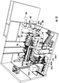
FIGS. 2A-2C show a multiple embodiment overviews of the treatment equipment. -
FIG. 3 shows an overview of the process described herein. - The novel biosolids treatment process and combination of equipment presents an alternative to the land application, incineration, composting, or landfilling of biosolids, all of which are increasingly problematic in biosolids management. The process, using the facility, converts dewatered municipal biosolids ("sludge cake") generated at wastewater treatment plants (WWTPs) to renewable energy and three value added products (low carbon ash, high carbon biochar, and Class A dried biosolids) preferably without the use of supplemental fuels (natural gas, oil, biomass, etc.), which are not required.
- An initial design of a first treatment facility's footprint was approximately 0.25 acres with site disturbance limited to the foundation footers and slab required for the storage and process buildings. A negative pressure one-story building houses the biosolids gasification and drying sections. The enclosed facility is not subject to leaching, runoff, or wind. There are no outfall pipes that discharge to surface streams or drainage channels and wastewater discharge from the facility may be routed to a wastewater treatment plant.
- Ancillary equipment and structures located adjacent to the gasifying and drying process building may include mechanical equipment for receiving, storing, and conveying biosolids into the building. Conveyance and storage equipment for the Class A products may also be housed in the ancillary building.
- Air emissions from the facility are very low to begin with and are further controlled by a wet scrubber and activated carbon filter. Air emissions from the facility are similar in content to combustion of natural gas.
- The waste treatment process involves the thermal drying of dewatered biosolid to produce a Class A biosolid that can be used as a fertilizer, soil conditioner, and/or a renewable fuel product. Class A biosolids meet the requirements established under 25 Pa. Code §271.932(a) in regard to pathogens and 25 Pa. Code §271.933(b)(1)-(8) relating to vector attraction reduction, (also found in US EPA Part 503 Biosolids Rule,
Chapters 2, 5, and 6), are nonliquid, and are unrecognizable as human waste. - The process may also produce a renewable fuel coproduct with as-is energy value ≥ 5,000 Btu/lb as defined in 25 Pa. Code §287.1 as a beneficial use product. Further, the biosolids gasifying drying facility satisfies the time-temperature requirement of Regime B as identified in Table 5-3 of US EPA Part 503 Biosolids Rule, Chapter 5 for Class A pathogen reduction.
- The facility reduces the attractiveness of biosolids to vectors by drying the biosolids to > 90% solids content as identified in Table 5-8, Option #8 of US EPA Part 503 Biosolids Rule, Chapter 5 for Class A vector attraction reduction. The system can process dewatered biosolids cake as wet as 15% total solids content.
- The unloading process and storage may be maintained at a negative pressure and minimal onsite storage in a building maintained at a negative pressure may ensure all odors are contained inside the building thereby minimizing nuisance complaints.
- To put the system in context, it may be helpful to review the process from the step of biosolids sludge delivery to the treatment system, it being understood that the delivery steps may be performed in many other ways.
-
FIG. 1 illustrates an overview of the sludge receiving andmetering facility 100, which includes the sludge receiving building 110 (that receives the trucks) and sludge metering building 120 (where certain measurements are taken the sludge is prepared before treatment). The sludge receiving building includes therollup door 112 that allows trucks to access thesludge receiving building 110 and in particular the building'sinterior unloading bay 114. The sludge receiving andmetering facility 100 includes anelevating conveyor 116 that conveys sludge received from the trucks upwards to ametering building conveyor 118 that spans thebuildings port 115 into thesludge metering bins 122 located in thesludge metering building 120. - Within the
metering building 120, sludge may be tested and stored before final transfer (which could be done via a treatment facility conveyor 124 (which may be a screw conveyor) that exits through atreatment port 125 between themetering building 120 and the treatment facility/building 200. Arrows indicate the direction of material flow. Within themetering building 120, technicians may test the sludge for chemical composition, moisture content, weight, volume. - The
metering bins 122 may be graduated indicating the volume at different levels. A technician may record the sludge level before and after filling eachmetering bin 120, calculating the displaced sludge volume, and thus the mass flow rate entering thetreatment building 200 can be calculated with the bulk density of the material. - As shown in
FIGS. 2A (a simple overview) and 2B/2C (a more detailed and thorough view)treatment facility conveyors 124 deliver the sludge to thetreatment building 200, and in particular a conventional biosolids mixer 210 (paddle, pug mill, pin mixer, or other) within atreatment building 200 where wet biosolids cake (average of 20% solids, ranging from 15% to 30% solids) is mixed with recirculated dried Class A product (average of 93% solids) from anoutput 222 of thedryer 220, to create a blended feed mixture (mixed biosolids) ranging between 50% to 75% total solids. The mixed biosolids are conveyed (viaconveyor 222a andvertical lift conveyor 222b) to the direct contact,rotary drum dryer 220 for heat treatment that yields Class A product and also sent to thegasifier 240 viaconveyors 222c and mixers to thegasifier metering bin 2030 as the exclusive fuel source for generating the thermal energy needed to dry the mixed biosolids to >90% total solids. The mixed biosolids are the sole energy source for the evaporation of water from the mixture. Thegasifier 240 described herein may be of the type described inUS Patent No. 6,948,436 , the contents of which are incorporated by reference as if fully set forth herein. - The biosolids gasifier 240 heats the wet mixed biosolids using self-sustaining heat recovery from the system in an oxygen deficient chamber where the biosolids are converted to volatile gases (syngas) and low carbon ash or high carbon biochar, depending upon process purpose. The ash/biochar is automatically conveyed from the system as a beneficial byproduct for use as a soil amendment, fertilizer, or activated carbon filter media (as described below).
- The volatile syngas is channeled into a separate chamber downstream from the
gasifier 240 to anoxidizer 230 where controlled combustion is achieved. Combustion occurs when adequate air is introduced to the syngas in the oxidizer balancing the combustion equation resulting in exothermic energy release achieving temperatures ranging between 1800F-2200F. - The hot flue gases leave the
oxidizer 230 and enter a flue gas tempering chamber (blend box) 235 where ambient air and moist recirculated dryer exhaust are mixed with the hot flue gas to achieve a controlled "tempered" flue gas temperature in the range of 700F - 1400F, depending on biosolids characteristics and process purpose. - The
blend box 235 is designed to mix the hot oxidizer flue gas (>2000F) with ambient air (+/- 70F) and moist recirculated dryer (dryer 220) exhaust (+/- 240F) to a set target temperature (700F - 1400F). The target temperature is achieved by controlling the induced ambient air with a temperature-controlled damper operating from a thermocouple placed in a strategic location within theblend box 235 and the recirculated dryer exhaust with a variable frequency drive (VFD) on a recirculation fan motor that allows the operator to vary the flow rate of the recirculated dryer exhaust. Together, these two control points enable an operator (or automated operating controls but discussed herein as operator) to achieve accurate and stable temperature control exiting theblend box 235. - Contained within the
blend box 235 is a shell and tube air-to-air heat exchanger designed to preheat ambient air for use in the gasification process (this gasifier air preheater is within theblend box 235, with visible inlet/outlets 237inFIG. 2C )) and further lower the flue gas temperature to a "target" temperature. Furthermore, the tubes of the gasifier air preheater cause flue gas turbulence ensuring complete blending of gases for a uniform gas temperature exiting theblend box 235. - When sludge characteristics and process purpose allow, a customized two-pass, crossflow, plume abatement heat exchanger 280 (plume abatement HX) is installed between the gasifier air preheater and the dryer inlet. The tempered flue gas exiting the
blend box 235 is used to heat the dryer exhaust in two steps. First, after passing through the mechanical cyclone (2050a, 2050b) and then thewet scrubber 2070 of the emission train (each removing further particulate, following the arrows and piping as shown), the saturated exhaust from thewet scrubber 2070 is routed throughpiping 281a to theplume abatement HX 280 where excess energy, not needed for the evaporation of moisture from the mixed biosolids, is used to heat the exhaust gases to a controlled temperature thereby dropping the relative humidity of the flue gas stream prior to entering, throughadditional piping 281b, a activated carbon filter (ACF) 282. Low relative humidity gas flow maximizes the performance of activated carbon. High temperature flue gas minimizes ACF performance so accurate temperature control of the heated gas may be a design consideration - After the
ACF 282, the flue gas passes through thepiping 281c in a second pass of theplume abatement HX 280 to superheat the exhaust to minimize plume before routing the exhaust throughpiping 281d to thefinal discharge point 284 to atmosphere. - The heat source for the plume abatement HX 28 is the tempered flue gas exiting the
blend box 235. In the same manner that it is important to control temperature entering theACF 282, control of the temperature of the hot flue gas may be maintained while entering thedryer 220. The dryer inlet temperature may be controlled using a system of dampers in the flue gas stream that direct flow through theplume abatement HX 280. In this manner, accurate control of both gas streams (entering theACF 282 and entering the dryer 220) may be controlled to target temperatures set by the operator. Target temperatures entering thedryer 220 may range between 600F - 1100F. Thedirect contact dryer 220 may be conventional to industry. - A portion of the dried Class A product (average of 93% solids) may be recirculated from the
dryer outlet 222 as discussed above for blending with the inbound wet biosolids cake. The ratio of dry to wet biosolids for the mixer is determined by aninline moisture sensor 212 on the discharge of themixer 210 and manually checked by periodic operator testing. - After much testing, the inventors found that flexibility to accurately control the mixer output to a range between 35% to 75% solids content is necessary to treat all varieties of municipal sludge with keeping below the sticky phase of the sludge, a phase that makes the operation challenging to manage. This mixed sludge quality is determined by the target fuel specifications for the
gasifier 240. - Target temperature flue gas exits the
blend box 235 andplume abatement HX 280 before entering adirect contact dryer 220 where it is the heat source for evaporating the water from dewatered mixed biosolids ranging between 35% to 75% solid content (same blended biosolids used for the gasifier fuel). The dried product may be conventionally sold as Class A product that is ≤ 10% MC (90% DM). The system may recycle the dried Class A product for mixing with incoming dewatered biosolids cake at ranging from 15% solids to >30% solids content. - The blended biosolid mixture ("mixed biosolids") may be used as the exclusive fuel for the
gasifier 240 and the input biosolids to thedirect contact dryer 220. With theplume abatement HX 280 installed, the closed-loop system is estimated to be +/- 94% efficient for energy repurposing. - The evaporated water from the biosolids pass from the
dryer 220, through a highefficiency cyclone collectors FIG. 2A ) to capture 99% of particulate matter larger than 10 micron (PM10), then through a three-stagewet scrubber system 2070 equipped with alkaline treatment to ensure the capture of the majority of the remaining PM and treat for residual odors and SO2 prior to emitting to the atmosphere. The clean water vapor plume is drawn from the system using an induceddraft fan 2010 that blows the moist exhaust through an activatedcarbon filter 2060 to perform final pollutant polishing prior to exiting thefacility stack 2020. - The treatment process produces three types of beneficial coproducts. The process begins by mixing dewatered biosolids cake (ranging from 82% water content to 70% water content) with recirculated dried Class A biosolids (+/- 7% water content) to create a resulting mixed biosolids (ranging between 50% water content to 25% water content) for use as the exclusive gasifier fuel and the inlet material to the dryer. The three coproducts generated from the system are:
- 1. Low carbon ash (LCA) - This coproduct has beneficial use as a fertilizer, alternative liming material for alkaline stabilization, and/or ingredient for improving the strength and porosity characteristics of building materials. The LCA is automatically conveyed out of the gasifier to an ash collection bin where it may be periodically hauled offsite.
- 2. High carbon activated biochar (HCAB) - This coproduct has beneficial use as a soil amendment, activated carbon filter media, and/or ingredient for improving the strength and porosity characteristics of building materials. The HCAB is automatically conveyed out of the gasifier to a collection bin where it may be periodically hauled offsite.
- 3. Excess dried Class A biosolids (7% water content) can be collected for use as a Class A fertilizer and/or alternative renewable fuel source. Class A Biosolids is conveyed to a collection bin where it may be periodically hauled offsite.
- As described herein, the
gasifier 240 may produce LCA and HCAB, while thedryer 220 produces the Class A biosolids. The dryer's Class A biosolid may be conveyed back to thegasifier 240, which converts all carbon in the overall system to energy, with LCA as the only byproduct. This is made possible using the plume abatement heater, the absence of which leaves a functioning system where excess energy is recovered in solid form with the gasifier producing LCA and the dryer produces Class A biosolids OR the gasifier produces only HCAB and no Class A product. - The treatment system gasifier/
oxidizer arrangement gasifier 240 and pulled into theoxidizer 230 by the draft that is established and maintained by an induced draft (ID)fan 2010 located at the end of the process following the wet scrubber and before the activated carbon filter. The production of syngas is an exothermic reaction resulting in temperatures (>900 F) adequate to sustain the carbon conversion operation and kill all pathogens. - In operation, the mixed biosolids fuel may remain in the
gasifier 240 at temperature > 900 F for 30 - 90 minutes. Thegasifier 240 operates under a controlled draft. - The resulting ash from the
gasifier 240 is one of the stated beneficial use products of the process. The ash may be stored in a covered 30-yard roll-off container providing weeks of storage. Once full, the roll-off container may be replaced with an empty 30-yard roll-off without stopping the process. - The duration of product exposure to elevated temperatures within the
gasifier 240 kills all pathogens for Class A product and may thermally destroy Per- and polyfluoroalkyl (PFAS) compounds that are extremely harmful to human health to trace limits. The solids content of >90% satisfies the VAR requirement for Class A product. The gasifier ash may be tested for metals content to prove their qualification as Class A land application product. In theoxidizer 230, the volatile syngas is mixed with ambient air to balance the combustion equation and oxidation occurs, reaching temperatures in excess of 2000 F, which may thermally destroy vapor phase PFAS compounds to trace limits. - A controlled and consistent temperature entering the
dryer 220 is achieved by mixing the hot flue gas from the oxidizer (>2000F) with ambient air and recirculated moist flue gas from thedryer 220 exhaust in a tempering chamber called the blend box. - Target dryer inlet temperature may be achieved with a temperature-controlled damper on the ambient air inlet. Ambient air supply for the blend box comes from the sludge receiving and storage and
metering buildings - The tempering air flow into the blend box may result in air changes every hour in the sludge storage rooms that exceed limits imposed for office space and hospitals.
- In addition to benefiting from its temperature cooling properties, recirculated flue gas is conventional practice for reducing NOx emissions. Once in the
dryer 220, the tempered flue gas comes in direct contact with the mixed biosolids evaporating the moisture to a dried solids condition of > 90% satisfying Class A requirements. - The dried biosolids product is one of the stated beneficial use products of the process described herein. The Class A dried biosolids product may be stored in a 40-yard roll-off container providing 10 days of storage. Once full, the roll-off container is replaced with an empty 40-yard roll-off without stopping the process.
- The duration of product exposure to elevated temperatures (mean temperature is > 450 F) within the dryer is 12 minutes satisfying the pathogen kill requirements for time and temperature for Class A product. The solids content of >90% satisfies a VAR requirement for Class A product. Dried biosolids may be tested for metals content to prove their qualification as Class A product. Furthermore, a proximate analysis may be performed on the dried solids to confirm the energy content is ≥ 5000 Btu/pound satisfying the requirement to sell the product as a renewable fuel.
- Air emissions are controlled with a high efficiency mechanical cyclone collector to capture >99% of particles larger than 10 microns. The flue gas stream exits the cyclone to a 3-stage wet scrubber where the final particulate matter may be captured prior to passing through an activated carbon filter prior to emitting to the atmosphere. The 3-stage wet scrubber is equipped with bleach and caustic soda to scrub odors and sulfur emissions, if necessary. The total wastewater from the process is scrubber blowdown which is routed to the headworks of the WWTP for processing.
- The treatment process satisfies the time-temperature requirement of Regime B as identified in Table 5-3 of USEPA Part 503 Biosolids Rule, Chapter 5 for Class A pathogen reduction and reduces the attractiveness of biosolids to vectors by drying the biosolids to > 90% solids content as identified in Table 5-8, Option #8 of USEPA Part 503 Biosolids Rule, Chapter 5 for Class A vector attraction reduction.
- Beneficial products produced from the treatment facility are Class A products for land application and renewable fuel coproducts.
- There may be two chemical storage tanks for the operation of a wet scrubber, which may not exceed 50 gallons each. One tank may contain 12.5% concentrated solution of sodium hypochlorite (NaOCL, bleach) and the other may contain a 25% concentrated solution of caustic soda (NaOH, sodium hydroxide).
- The sodium hypochlorite and caustic soda storage containers may be mounted above a containment basin. This basin nay be sized for full leakage potential and contain the material from both tanks if they both emptied at the same time.
- In the event of a spill, the contents within the containment basin may be pumped into a secure container and properly disposed in an approved landfill. Operator protection is provided with a pull chain activated, heated shower with integral eye wash station located immediately adjacent to the chemical containment basin. The shower may drain to the headworks of WWTP.
- There may be discharge water produced from the wet scrubber, which may be routed directly to a wastewater treatment facility (WWTP).
- A facility such as the one proposed may be chosen based on a desire to harness the currently land applied or landfilled dewatered sludge cake produced by a WWTP. There are more than 16,000 WWTP in the United States and all have a sludge disposal problem.
-
FIG. 3 shows a process overview in which inputs are shown in black boxes, processing steps are in a light grey, and outputs are in a darker grey. The dewatered cake 302 (which may include 20% solids not digested) is fed into themixer 304, which combines the sludge and cake. The output from themixer 304 is fed to afluid lift gasifier 306 operating at 1400-1700 degrees F and thedryer 310. The fluidlift gasifier output 306 is then fed to thesyngas oxidizer 308 burning CO and H2 operating at a temperature of 2,000-2,200 degrees F, which produces three outputs including continued process output of that is transported to thedryer 310. - The
dryer 310, using both the feeds directed to it, produces a vapor fed to thescrubber 312 that produceswater vapor 314 as output. The dryer also produces Class A/EQ biosolids 316 that may be used as renewable solid fuel for land applications. - As mentioned, the
oxidizer 306 may have two other outputs, which includeconcentrated minerals 320 andcustom biochars 322, the former of which may be used for phosphorous alkaline stabilization and the later of which may be used for adsorption/filtration soil amendment. - The process shown figuratively in
FIG. 3 produces three types of beneficial use products from different process apparatuses. The project may not generate a waste other than blowdown from the three-stage wet scrubber that may be discharged to the headworks of the WWTP for treatment. Said another way, the process may produce beneficial use products (BUPs), not wastes. - Dewatered biosolids cake ranging between 82% water content to 70% water content may be mixed with self-generated dried Class A biosolids at < 10% water content to create a resulting mixed sludge for the gasifier and the dryer. This mixed sludge may be introduced into the gasifier at high temperatures (900F - 1600F) where pyrolysis occurs, and volatile gases are removed and oxidized. After moving through the gasifier, two BUPs can result depending on the energy content of the biosolids cake:
- 1) Low carbon ash- This product is conveyed out of the gasifier to an ash trailer where it may be periodically sold for use as an all-natural fertilizer or a strength and hydroscopic enhancement ingredient for construction materials. If no market is available, the low carbon ash is benign and can be disposed in a landfill.
- 2) High carbon activated biochar- This product is conveyed out of the gasifier to an ash trailer where it may be periodically sold for use as an all-natural soil amendment, alternative to activated carbon filtration and adsorption media, or a strength and hydroscopic enhancement ingredient for construction materials. If no market is available, the biochar is benign and can be disposed in a landfill.
The thermal drying process may include of a direct contact rotary drum dryer with all associated product collection equipment. The mixed sludge that is sent to the dryer exits the dryer at 7% water content which may then be recycled back to the process to be incorporated with the dewatered biosolids cake via a mixer. A volume of recycled dried product can be adjusted for processing efficiencies. In this event, the non-recycled portion of the dried Class A biosolids is collected for sale as fertilizer or as a renewable energy fuel in the form of alternative coal. If no market is available, the Class A product can be used as landfill cover. - 3) Class A Biosolids- This product is conveyed from the dryer outlet to Class A Biosolids bin where it may be temporarily stored before sold for beneficial uses.
- Water blowdown from the wet scrubber may be sent directly back to the headworks of the WWTP to be treated. Water vapor from the drying process may exit the system via the exhaust stack and be sent to atmosphere.
- One point worth noting is that the prior art systems have fed the dryer with a fixed flow rate of sludge and changed the firing rate of fossil fuel burners to react to the evaporation rate needed in the dryer. The system here can work differently than this by fixing the firing rate of the gasifier since the energy conversion through gasification must be controlled and then vary the feed rate to the dryer based on the available energy from the gasifier. This one control change is not done in the drying industry.
- Another notable unconventional control logic difference is that the induced draft (ID)
fan 2010 is variable frequency driven (VFD) to control draft in the gasifier. The ID fan increases and decreases speed to maintain a constant draft in the gasifier when flue gas temperature controllers (induction air damper inblend box 235 and dryer exhaust recirculation fan in blend box) change the total system flue gas flow. A VFD ID fan is critical to maintain desired gasification performance whereas conventional biosolids drying systems have a fixedspeed ID fan 2010 because a controlled draft is not important with fossil fuel burners. - In the process, as can be seen, the placement of the oxidizer is before the dryer rather than industry convention being the last piece of equipment prior to atmospheric discharge.
- While the invention has been described as shown and described herein, a person of ordinary skill in the art would understand that various changes or modifications may be made thereto without departing from the scope of the claims.
Claims (15)
- A biosolids treatment system that treats human biosolids to produce beneficial use products including low carbon ash, high carbon activated biochar, and Class A biosolids, the system comprising:a variable feed conveyor that conveys a biosolid feed into a dryer;a dryer that dries the biosolid feed to a predetermined moisture content to create at least one beneficial use products, wherein the predetermined moisture content is controlled by varying a speed of the variable feed conveyor; anda gasifier that converts the biosolid feed into usable thermal energy for system use and at least one of the beneficial use products.
- The biosolids treatment system of claim 1, wherein the dryer is adapted to be able to create low carbon ash and the gasifier is adapted to be able to create high carbon activated biochar and Class A biosolids.
- The biosolids treatment system of claim 1 or claim 2, wherein the treatment system includes a blended air intake for tempering flue gas entering a dryer to form blended air for controlling a target temperature in the dryer.
- The biosolids treatment system of any of claims 1 to 3, wherein the treatment system includes a fan to recirculate moist dryer exhaust for tempering flue gas entering a dryer to form blended air, wherein the blended air controls a target temperature in the dryer and reduces NOx emissions.
- The biosolids treatment system of any of the previous claims, wherein the system is configured to control carbon content of the biochar.
- The biosolids treatment system of any of the previous claims, wherein the beneficial use product is biochar and said biochar is used to filter air emissions from the system prior to discharge to atmosphere.
- The biosolids treatment system of any of the previous claims, wherein the beneficial use product is biochar and said biochar is mixed with the human biosolids as exclusive fuel for the gasifier.
- The biosolids treatment system of any of the previous claims, further including a water quench that cools the said at least one beneficial use product prior to leaving the gasifier and/or serves as an air lock to the gasifier enabling a negative pressure draft to be controlled within the gasifier.
- The biosolids treatment system of claim 1, wherein the treatment system is capable of using different moisture content biosolid fuel sources and preferably is configured to use comingled materials generated by a wastewater treatment facility (WWTF) including grit and screenings, fats/oils/grease (FOG), anaerobically digested biosolids, biosolids post thermal hydrolysis treatment, primary/secondary waste activate sludge, non-activated sludge in varying percent of composition as fuel sources for the gasifier without need for supplemental fuel.
- The biosolids treatment system of any of the previous claims, further including a plume abatement heat exchanger that treats gas exiting the dryer before sending the gas to an activated carbon filter.
- The biosolids treatment system of claim 10, wherein gas exiting the activated carbon filter returns to the plume abatement heat exchanger for superheating before emission to atmosphere to minimize plume created by moisture in the gas.
- The biosolids treatment system of claim 10 or claim 11, further including a control system that controls a wet scrubber that treats the gas exiting the dryer before the gas is treated by the plume abatement heat exchanger.
- The biosolids treatment system of claim 1, further comprising an oxidizer located between the gasifier and dryer.
- A method of operating a biosolids treatment system according to any of the previous claims that treats human biosolids to produce three beneficial use products: low carbon ash, high carbon activated biochar, and Class A biosolids, wherein a feed rate into a dryer is modified in response to a measured moisture content of the human biosolids to correspond with a fixed heating rate occurring in a gasifier.
- The method of claim 14, wherein the treatment time and temperature within the gasifier and /or an oxidizer are adapted to thermally destroy Per- and polyfluoroalkyl substances (PFAS).
Priority Applications (1)
| Application Number | Priority Date | Filing Date | Title |
|---|---|---|---|
| EP25189676.7A EP4606878A3 (en) | 2019-07-29 | 2020-08-19 | Biosolid treatment process and system |
Applications Claiming Priority (2)
| Application Number | Priority Date | Filing Date | Title |
|---|---|---|---|
| US201962879929P | 2019-07-29 | 2019-07-29 | |
| US16/942,635 US11629301B2 (en) | 2019-07-29 | 2020-07-29 | Biosolid treatment process and system |
Related Child Applications (1)
| Application Number | Title | Priority Date | Filing Date |
|---|---|---|---|
| EP25189676.7A Division EP4606878A3 (en) | 2019-07-29 | 2020-08-19 | Biosolid treatment process and system |
Publications (3)
| Publication Number | Publication Date |
|---|---|
| EP3945077A1 true EP3945077A1 (en) | 2022-02-02 |
| EP3945077B1 EP3945077B1 (en) | 2025-07-16 |
| EP3945077C0 EP3945077C0 (en) | 2025-07-16 |
Family
ID=74259972
Family Applications (2)
| Application Number | Title | Priority Date | Filing Date |
|---|---|---|---|
| EP20191836.4A Active EP3945077B1 (en) | 2019-07-29 | 2020-08-19 | Biosolid treatment process and system |
| EP25189676.7A Pending EP4606878A3 (en) | 2019-07-29 | 2020-08-19 | Biosolid treatment process and system |
Family Applications After (1)
| Application Number | Title | Priority Date | Filing Date |
|---|---|---|---|
| EP25189676.7A Pending EP4606878A3 (en) | 2019-07-29 | 2020-08-19 | Biosolid treatment process and system |
Country Status (3)
| Country | Link |
|---|---|
| US (1) | US11629301B2 (en) |
| EP (2) | EP3945077B1 (en) |
| AU (2) | AU2020220143B2 (en) |
Families Citing this family (4)
| Publication number | Priority date | Publication date | Assignee | Title |
|---|---|---|---|---|
| US11434160B1 (en) | 2020-09-01 | 2022-09-06 | Wm Intellectual Property Holdings, L.L.C. | System and method for processing of sewage sludge using pyrolysis to eliminate PFAS and other undesirable materials |
| EP4275239A4 (en) | 2021-01-11 | 2024-12-18 | 6K Inc. | METHODS AND SYSTEMS FOR RECOVERY OF LI-ION CATHODE MATERIALS USING MICROWAVE PLASMA PROCESSING |
| US11339337B1 (en) * | 2021-08-19 | 2022-05-24 | Aries Clean Technologies Llc | Elimination of poly- and perfluoro alkyl substances (PFAS) in a wastewater biosolids gasification process using a thermal oxidizer and hydrated lime injection |
| WO2025049798A1 (en) * | 2023-08-31 | 2025-03-06 | 6K Inc. | Systems, methods, and devices for destruction of per- and polyfluoroalkyl substances (pfas) and for reactivating spent activated carbon |
Citations (6)
| Publication number | Priority date | Publication date | Assignee | Title |
|---|---|---|---|---|
| US6948436B2 (en) | 2003-11-10 | 2005-09-27 | Rem Engineereing, Inc. | Method and apparatus for the gasification and combustion of animal waste, human waste, and/or biomass using a moving grate over a stationary perforated plate in a configured chamber |
| US20080209753A1 (en) * | 2007-01-16 | 2008-09-04 | Nathaniel Lee Smith | Manure removal and drying system |
| US20110061298A1 (en) * | 2009-09-14 | 2011-03-17 | General Electric Company | Method and apparatus for drying solid feedstock using steam |
| DE102011004788A1 (en) * | 2011-02-25 | 2012-08-30 | Huber Se | Plant and method for drying moist material |
| US8832962B2 (en) * | 2009-11-23 | 2014-09-16 | Degremont | Method and facility for drying slurry-like materials, in particular sludge from wastewater treatment plants |
| EP3085671A1 (en) * | 2015-04-21 | 2016-10-26 | Huber SE | Method for drying moist material and drying system |
Family Cites Families (8)
| Publication number | Priority date | Publication date | Assignee | Title |
|---|---|---|---|---|
| US4497637A (en) * | 1982-11-22 | 1985-02-05 | Georgia Tech Research Institute | Thermochemical conversion of biomass to syngas via an entrained pyrolysis/gasification process |
| JP5086253B2 (en) * | 2005-06-28 | 2012-11-28 | アフォグナック ネイティブ コーポレーション | Automatic modular biomass power generation method and apparatus |
| JP4939511B2 (en) * | 2008-10-29 | 2012-05-30 | 三菱重工業株式会社 | Coal gasification combined power generation facility |
| US8691115B2 (en) * | 2010-04-29 | 2014-04-08 | Indiana University Research And Technology Corporation | System and method for controlling char in biomass reactors |
| CA2853099A1 (en) * | 2011-10-21 | 2013-04-25 | Therma-Flite, Inc. | Gasifying system and method, and waste-treatment system and method including the same |
| US20130247448A1 (en) * | 2012-03-26 | 2013-09-26 | Sundrop Fuels, Inc. | Optimization of torrefaction volatiles for producing liquid fuel from biomass |
| US8721748B1 (en) * | 2013-01-28 | 2014-05-13 | PHG Energy, LLC | Device with dilated oxidation zone for gasifying feedstock |
| GB2539447B (en) * | 2015-06-16 | 2017-07-05 | Sage & Time Llp | Converting a carbonaceous feedstock into a product gas e.g. methane gas |
-
2020
- 2020-07-29 US US16/942,635 patent/US11629301B2/en active Active
- 2020-08-19 EP EP20191836.4A patent/EP3945077B1/en active Active
- 2020-08-19 EP EP25189676.7A patent/EP4606878A3/en active Pending
- 2020-08-20 AU AU2020220143A patent/AU2020220143B2/en active Active
-
2025
- 2025-12-08 AU AU2025275320A patent/AU2025275320A1/en active Pending
Patent Citations (6)
| Publication number | Priority date | Publication date | Assignee | Title |
|---|---|---|---|---|
| US6948436B2 (en) | 2003-11-10 | 2005-09-27 | Rem Engineereing, Inc. | Method and apparatus for the gasification and combustion of animal waste, human waste, and/or biomass using a moving grate over a stationary perforated plate in a configured chamber |
| US20080209753A1 (en) * | 2007-01-16 | 2008-09-04 | Nathaniel Lee Smith | Manure removal and drying system |
| US20110061298A1 (en) * | 2009-09-14 | 2011-03-17 | General Electric Company | Method and apparatus for drying solid feedstock using steam |
| US8832962B2 (en) * | 2009-11-23 | 2014-09-16 | Degremont | Method and facility for drying slurry-like materials, in particular sludge from wastewater treatment plants |
| DE102011004788A1 (en) * | 2011-02-25 | 2012-08-30 | Huber Se | Plant and method for drying moist material |
| EP3085671A1 (en) * | 2015-04-21 | 2016-10-26 | Huber SE | Method for drying moist material and drying system |
Also Published As
| Publication number | Publication date |
|---|---|
| AU2025275320A1 (en) | 2026-01-15 |
| EP3945077B1 (en) | 2025-07-16 |
| EP3945077C0 (en) | 2025-07-16 |
| EP4606878A3 (en) | 2025-11-26 |
| EP4606878A2 (en) | 2025-08-27 |
| AU2020220143B2 (en) | 2025-11-27 |
| AU2020220143A1 (en) | 2021-02-18 |
| US11629301B2 (en) | 2023-04-18 |
| US20210032552A1 (en) | 2021-02-04 |
Similar Documents
| Publication | Publication Date | Title |
|---|---|---|
| EP3945077B1 (en) | Biosolid treatment process and system | |
| DK1799796T3 (en) | Slurry drainage and sludge conversion into a renewable fuel | |
| AU2005254232B2 (en) | Method and system for the recycling of municipal solid wastes, and exploitation of the wasted solid recovery fuel | |
| US20100289270A1 (en) | Pyrolytic thermal conversion system | |
| ZA200703757B (en) | Slurry dewatering and conversion of biosolids to a renewable fuel | |
| KR200218031Y1 (en) | Multipurpose Refuse Ram Feed Incinerator | |
| KR101999650B1 (en) | Hybrid Sludge Fuel, Manufacturing Method and System of Fuel Production thereof | |
| US20130186810A1 (en) | System and Method for Processing Alternate Fuel Sources | |
| US20240189876A1 (en) | Biosolid treatment process and system | |
| CA3090521A1 (en) | Biosolid treatment process and system | |
| US11965651B2 (en) | Process for producing biomass by treatment of organic waste with two-step drying | |
| Plavac et al. | Sustainable waste management with mechanical biological treatment and energy utilization | |
| JP2020172654A (en) | Sludge fuel conversion equipment, sludge fuel conversion system, sludge fuel utilization type factory and solid fuel manufacturing method | |
| KR102858320B1 (en) | hydrothermal treatment system | |
| EP1955981A2 (en) | Method of energy appreciation of the products from purification of stillage from ethanol production and the equipment for implementation of this method | |
| JP2023101485A (en) | Heat recovery device from sludge, heat recovery system from sludge, and factory utilizing heat recovered from sludge | |
| CN105753274B (en) | A sludge disposal system and disposal process | |
| US20200200383A1 (en) | Non-polluting Biomass Waste Processor, Components and Processes for a Use by a Municipality, Industrial, Forestry and/or Agricultural Facility | |
| US20210031250A1 (en) | Non-polluting Biomass Waste Processor, Components and Processes for Use by a Municipality, Industrial, Forestry and/or Agricultural Facility | |
| da Costa et al. | A new conception to Biosludge treatment and destination in Kraft pulp mills | |
| Beik | Chemical process design of solid waste management for use in railway rolling stock | |
| Dorn et al. | Biosolids Recycling Facility–Sludge to Glass Aggregate | |
| Igoe et al. | Biosolids Drying: Solving Municipal Regulation and Cost Problems | |
| Plavac et al. | Održivo gospodarenje otpadom s mehaničko biološkom obradom i energetskim iskorištavanjem | |
| Stanke et al. | DIRECT FEED TECHNOLOGY FOR THERMAL DRYING OF BIOSOLIDS IN A FLUIDIZED BED |
Legal Events
| Date | Code | Title | Description |
|---|---|---|---|
| PUAI | Public reference made under article 153(3) epc to a published international application that has entered the european phase |
Free format text: ORIGINAL CODE: 0009012 |
|
| STAA | Information on the status of an ep patent application or granted ep patent |
Free format text: STATUS: THE APPLICATION HAS BEEN PUBLISHED |
|
| AK | Designated contracting states |
Kind code of ref document: A1 Designated state(s): AL AT BE BG CH CY CZ DE DK EE ES FI FR GB GR HR HU IE IS IT LI LT LU LV MC MK MT NL NO PL PT RO RS SE SI SK SM TR |
|
| STAA | Information on the status of an ep patent application or granted ep patent |
Free format text: STATUS: REQUEST FOR EXAMINATION WAS MADE |
|
| 17P | Request for examination filed |
Effective date: 20220801 |
|
| RBV | Designated contracting states (corrected) |
Designated state(s): AL AT BE BG CH CY CZ DE DK EE ES FI FR GB GR HR HU IE IS IT LI LT LU LV MC MK MT NL NO PL PT RO RS SE SI SK SM TR |
|
| GRAP | Despatch of communication of intention to grant a patent |
Free format text: ORIGINAL CODE: EPIDOSNIGR1 |
|
| STAA | Information on the status of an ep patent application or granted ep patent |
Free format text: STATUS: GRANT OF PATENT IS INTENDED |
|
| GRAS | Grant fee paid |
Free format text: ORIGINAL CODE: EPIDOSNIGR3 |
|
| INTG | Intention to grant announced |
Effective date: 20250507 |
|
| GRAA | (expected) grant |
Free format text: ORIGINAL CODE: 0009210 |
|
| STAA | Information on the status of an ep patent application or granted ep patent |
Free format text: STATUS: THE PATENT HAS BEEN GRANTED |
|
| AK | Designated contracting states |
Kind code of ref document: B1 Designated state(s): AL AT BE BG CH CY CZ DE DK EE ES FI FR GB GR HR HU IE IS IT LI LT LU LV MC MK MT NL NO PL PT RO RS SE SI SK SM TR |
|
| REG | Reference to a national code |
Ref country code: GB Ref legal event code: FG4D |
|
| REG | Reference to a national code |
Ref country code: CH Ref legal event code: EP Ref country code: DE Ref legal event code: R096 Ref document number: 602020054502 Country of ref document: DE |
|
| REG | Reference to a national code |
Ref country code: IE Ref legal event code: FG4D |
|
| U01 | Request for unitary effect filed |
Effective date: 20250808 |
|
| U07 | Unitary effect registered |
Designated state(s): AT BE BG DE DK EE FI FR IT LT LU LV MT NL PT RO SE SI Effective date: 20250820 |
|
| U20 | Renewal fee for the european patent with unitary effect paid |
Year of fee payment: 6 Effective date: 20250909 |
|
| PGFP | Annual fee paid to national office [announced via postgrant information from national office to epo] |
Ref country code: GB Payment date: 20250904 Year of fee payment: 6 |
|
| PG25 | Lapsed in a contracting state [announced via postgrant information from national office to epo] |
Ref country code: IS Free format text: LAPSE BECAUSE OF FAILURE TO SUBMIT A TRANSLATION OF THE DESCRIPTION OR TO PAY THE FEE WITHIN THE PRESCRIBED TIME-LIMIT Effective date: 20251116 |
|
| PG25 | Lapsed in a contracting state [announced via postgrant information from national office to epo] |
Ref country code: NO Free format text: LAPSE BECAUSE OF FAILURE TO SUBMIT A TRANSLATION OF THE DESCRIPTION OR TO PAY THE FEE WITHIN THE PRESCRIBED TIME-LIMIT Effective date: 20251016 |
|
| PG25 | Lapsed in a contracting state [announced via postgrant information from national office to epo] |
Ref country code: HR Free format text: LAPSE BECAUSE OF FAILURE TO SUBMIT A TRANSLATION OF THE DESCRIPTION OR TO PAY THE FEE WITHIN THE PRESCRIBED TIME-LIMIT Effective date: 20250716 |
|
| PG25 | Lapsed in a contracting state [announced via postgrant information from national office to epo] |
Ref country code: GR Free format text: LAPSE BECAUSE OF FAILURE TO SUBMIT A TRANSLATION OF THE DESCRIPTION OR TO PAY THE FEE WITHIN THE PRESCRIBED TIME-LIMIT Effective date: 20251017 |
|
| PG25 | Lapsed in a contracting state [announced via postgrant information from national office to epo] |
Ref country code: PL Free format text: LAPSE BECAUSE OF FAILURE TO SUBMIT A TRANSLATION OF THE DESCRIPTION OR TO PAY THE FEE WITHIN THE PRESCRIBED TIME-LIMIT Effective date: 20250716 |
|
| PG25 | Lapsed in a contracting state [announced via postgrant information from national office to epo] |
Ref country code: RS Free format text: LAPSE BECAUSE OF FAILURE TO SUBMIT A TRANSLATION OF THE DESCRIPTION OR TO PAY THE FEE WITHIN THE PRESCRIBED TIME-LIMIT Effective date: 20251016 |
|
| PG25 | Lapsed in a contracting state [announced via postgrant information from national office to epo] |
Ref country code: ES Free format text: LAPSE BECAUSE OF FAILURE TO SUBMIT A TRANSLATION OF THE DESCRIPTION OR TO PAY THE FEE WITHIN THE PRESCRIBED TIME-LIMIT Effective date: 20250716 |
|
| REG | Reference to a national code |
Ref country code: CH Ref legal event code: H13 Free format text: ST27 STATUS EVENT CODE: U-0-0-H10-H13 (AS PROVIDED BY THE NATIONAL OFFICE) Effective date: 20260324 |
|
| PG25 | Lapsed in a contracting state [announced via postgrant information from national office to epo] |
Ref country code: SM Free format text: LAPSE BECAUSE OF FAILURE TO SUBMIT A TRANSLATION OF THE DESCRIPTION OR TO PAY THE FEE WITHIN THE PRESCRIBED TIME-LIMIT Effective date: 20250716 |
|
| PG25 | Lapsed in a contracting state [announced via postgrant information from national office to epo] |
Ref country code: CH Free format text: LAPSE BECAUSE OF NON-PAYMENT OF DUE FEES Effective date: 20250831 Ref country code: CZ Free format text: LAPSE BECAUSE OF FAILURE TO SUBMIT A TRANSLATION OF THE DESCRIPTION OR TO PAY THE FEE WITHIN THE PRESCRIBED TIME-LIMIT Effective date: 20250716 |
|
| PG25 | Lapsed in a contracting state [announced via postgrant information from national office to epo] |
Ref country code: SK Free format text: LAPSE BECAUSE OF FAILURE TO SUBMIT A TRANSLATION OF THE DESCRIPTION OR TO PAY THE FEE WITHIN THE PRESCRIBED TIME-LIMIT Effective date: 20250716 |