EP3944816A1 - Image processing apparatus, imaging system, image processing method, and storage medium - Google Patents
Image processing apparatus, imaging system, image processing method, and storage medium Download PDFInfo
- Publication number
- EP3944816A1 EP3944816A1 EP21186878.1A EP21186878A EP3944816A1 EP 3944816 A1 EP3944816 A1 EP 3944816A1 EP 21186878 A EP21186878 A EP 21186878A EP 3944816 A1 EP3944816 A1 EP 3944816A1
- Authority
- EP
- European Patent Office
- Prior art keywords
- radiation image
- image
- subject
- radiation
- processing apparatus
- Prior art date
- Legal status (The legal status is an assumption and is not a legal conclusion. Google has not performed a legal analysis and makes no representation as to the accuracy of the status listed.)
- Granted
Links
Images




Classifications
-
- A—HUMAN NECESSITIES
- A61—MEDICAL OR VETERINARY SCIENCE; HYGIENE
- A61B—DIAGNOSIS; SURGERY; IDENTIFICATION
- A61B6/00—Apparatus or devices for radiation diagnosis; Apparatus or devices for radiation diagnosis combined with radiation therapy equipment
- A61B6/52—Devices using data or image processing specially adapted for radiation diagnosis
- A61B6/5258—Devices using data or image processing specially adapted for radiation diagnosis involving detection or reduction of artifacts or noise
-
- A—HUMAN NECESSITIES
- A61—MEDICAL OR VETERINARY SCIENCE; HYGIENE
- A61B—DIAGNOSIS; SURGERY; IDENTIFICATION
- A61B6/00—Apparatus or devices for radiation diagnosis; Apparatus or devices for radiation diagnosis combined with radiation therapy equipment
- A61B6/58—Testing, adjusting or calibrating thereof
- A61B6/582—Calibration
-
- H—ELECTRICITY
- H04—ELECTRIC COMMUNICATION TECHNIQUE
- H04N—PICTORIAL COMMUNICATION, e.g. TELEVISION
- H04N25/00—Circuitry of solid-state image sensors [SSIS]; Control thereof
- H04N25/40—Extracting pixel data from image sensors by controlling scanning circuits, e.g. by modifying the number of pixels sampled or to be sampled
-
- A—HUMAN NECESSITIES
- A61—MEDICAL OR VETERINARY SCIENCE; HYGIENE
- A61B—DIAGNOSIS; SURGERY; IDENTIFICATION
- A61B5/00—Measuring for diagnostic purposes; Identification of persons
- A61B5/0033—Features or image-related aspects of imaging apparatus, e.g. for MRI, optical tomography or impedance tomography apparatus; Arrangements of imaging apparatus in a room
- A61B5/0035—Features or image-related aspects of imaging apparatus, e.g. for MRI, optical tomography or impedance tomography apparatus; Arrangements of imaging apparatus in a room adapted for acquisition of images from more than one imaging mode, e.g. combining MRI and optical tomography
-
- A—HUMAN NECESSITIES
- A61—MEDICAL OR VETERINARY SCIENCE; HYGIENE
- A61B—DIAGNOSIS; SURGERY; IDENTIFICATION
- A61B5/00—Measuring for diagnostic purposes; Identification of persons
- A61B5/24—Detecting, measuring or recording bioelectric or biomagnetic signals of the body or parts thereof
- A61B5/242—Detecting biomagnetic fields, e.g. magnetic fields produced by bioelectric currents
-
- A—HUMAN NECESSITIES
- A61—MEDICAL OR VETERINARY SCIENCE; HYGIENE
- A61B—DIAGNOSIS; SURGERY; IDENTIFICATION
- A61B6/00—Apparatus or devices for radiation diagnosis; Apparatus or devices for radiation diagnosis combined with radiation therapy equipment
-
- A—HUMAN NECESSITIES
- A61—MEDICAL OR VETERINARY SCIENCE; HYGIENE
- A61B—DIAGNOSIS; SURGERY; IDENTIFICATION
- A61B6/00—Apparatus or devices for radiation diagnosis; Apparatus or devices for radiation diagnosis combined with radiation therapy equipment
- A61B6/40—Arrangements for generating radiation specially adapted for radiation diagnosis
- A61B6/4007—Arrangements for generating radiation specially adapted for radiation diagnosis characterised by using a plurality of source units
-
- A—HUMAN NECESSITIES
- A61—MEDICAL OR VETERINARY SCIENCE; HYGIENE
- A61B—DIAGNOSIS; SURGERY; IDENTIFICATION
- A61B6/00—Apparatus or devices for radiation diagnosis; Apparatus or devices for radiation diagnosis combined with radiation therapy equipment
- A61B6/50—Apparatus or devices for radiation diagnosis; Apparatus or devices for radiation diagnosis combined with radiation therapy equipment specially adapted for specific body parts; specially adapted for specific clinical applications
- A61B6/506—Apparatus or devices for radiation diagnosis; Apparatus or devices for radiation diagnosis combined with radiation therapy equipment specially adapted for specific body parts; specially adapted for specific clinical applications for diagnosis of nerves
-
- A—HUMAN NECESSITIES
- A61—MEDICAL OR VETERINARY SCIENCE; HYGIENE
- A61B—DIAGNOSIS; SURGERY; IDENTIFICATION
- A61B6/00—Apparatus or devices for radiation diagnosis; Apparatus or devices for radiation diagnosis combined with radiation therapy equipment
- A61B6/52—Devices using data or image processing specially adapted for radiation diagnosis
- A61B6/5205—Devices using data or image processing specially adapted for radiation diagnosis involving processing of raw data to produce diagnostic data
-
- A—HUMAN NECESSITIES
- A61—MEDICAL OR VETERINARY SCIENCE; HYGIENE
- A61B—DIAGNOSIS; SURGERY; IDENTIFICATION
- A61B6/00—Apparatus or devices for radiation diagnosis; Apparatus or devices for radiation diagnosis combined with radiation therapy equipment
- A61B6/52—Devices using data or image processing specially adapted for radiation diagnosis
- A61B6/5211—Devices using data or image processing specially adapted for radiation diagnosis involving processing of medical diagnostic data
-
- A—HUMAN NECESSITIES
- A61—MEDICAL OR VETERINARY SCIENCE; HYGIENE
- A61B—DIAGNOSIS; SURGERY; IDENTIFICATION
- A61B6/00—Apparatus or devices for radiation diagnosis; Apparatus or devices for radiation diagnosis combined with radiation therapy equipment
- A61B6/52—Devices using data or image processing specially adapted for radiation diagnosis
- A61B6/5211—Devices using data or image processing specially adapted for radiation diagnosis involving processing of medical diagnostic data
- A61B6/5229—Devices using data or image processing specially adapted for radiation diagnosis involving processing of medical diagnostic data combining image data of a patient, e.g. combining a functional image with an anatomical image
- A61B6/5235—Devices using data or image processing specially adapted for radiation diagnosis involving processing of medical diagnostic data combining image data of a patient, e.g. combining a functional image with an anatomical image combining images from the same or different ionising radiation imaging techniques, e.g. PET and CT
- A61B6/5241—Devices using data or image processing specially adapted for radiation diagnosis involving processing of medical diagnostic data combining image data of a patient, e.g. combining a functional image with an anatomical image combining images from the same or different ionising radiation imaging techniques, e.g. PET and CT combining overlapping images of the same imaging modality, e.g. by stitching
-
- A—HUMAN NECESSITIES
- A61—MEDICAL OR VETERINARY SCIENCE; HYGIENE
- A61B—DIAGNOSIS; SURGERY; IDENTIFICATION
- A61B6/00—Apparatus or devices for radiation diagnosis; Apparatus or devices for radiation diagnosis combined with radiation therapy equipment
- A61B6/52—Devices using data or image processing specially adapted for radiation diagnosis
- A61B6/5211—Devices using data or image processing specially adapted for radiation diagnosis involving processing of medical diagnostic data
- A61B6/5229—Devices using data or image processing specially adapted for radiation diagnosis involving processing of medical diagnostic data combining image data of a patient, e.g. combining a functional image with an anatomical image
- A61B6/5247—Devices using data or image processing specially adapted for radiation diagnosis involving processing of medical diagnostic data combining image data of a patient, e.g. combining a functional image with an anatomical image combining images from an ionising-radiation diagnostic technique and a non-ionising radiation diagnostic technique, e.g. X-ray and ultrasound
-
- A—HUMAN NECESSITIES
- A61—MEDICAL OR VETERINARY SCIENCE; HYGIENE
- A61B—DIAGNOSIS; SURGERY; IDENTIFICATION
- A61B6/00—Apparatus or devices for radiation diagnosis; Apparatus or devices for radiation diagnosis combined with radiation therapy equipment
- A61B6/54—Control of apparatus or devices for radiation diagnosis
- A61B6/547—Control of apparatus or devices for radiation diagnosis involving tracking of position of the device or parts of the device
-
- G—PHYSICS
- G06—COMPUTING OR CALCULATING; COUNTING
- G06V—IMAGE OR VIDEO RECOGNITION OR UNDERSTANDING
- G06V10/00—Arrangements for image or video recognition or understanding
- G06V10/40—Extraction of image or video features
-
- G—PHYSICS
- G16—INFORMATION AND COMMUNICATION TECHNOLOGY [ICT] SPECIALLY ADAPTED FOR SPECIFIC APPLICATION FIELDS
- G16H—HEALTHCARE INFORMATICS, i.e. INFORMATION AND COMMUNICATION TECHNOLOGY [ICT] SPECIALLY ADAPTED FOR THE HANDLING OR PROCESSING OF MEDICAL OR HEALTHCARE DATA
- G16H30/00—ICT specially adapted for the handling or processing of medical images
- G16H30/20—ICT specially adapted for the handling or processing of medical images for handling medical images, e.g. DICOM, HL7 or PACS
-
- G—PHYSICS
- G16—INFORMATION AND COMMUNICATION TECHNOLOGY [ICT] SPECIALLY ADAPTED FOR SPECIFIC APPLICATION FIELDS
- G16H—HEALTHCARE INFORMATICS, i.e. INFORMATION AND COMMUNICATION TECHNOLOGY [ICT] SPECIALLY ADAPTED FOR THE HANDLING OR PROCESSING OF MEDICAL OR HEALTHCARE DATA
- G16H30/00—ICT specially adapted for the handling or processing of medical images
- G16H30/40—ICT specially adapted for the handling or processing of medical images for processing medical images, e.g. editing
-
- H—ELECTRICITY
- H04—ELECTRIC COMMUNICATION TECHNIQUE
- H04N—PICTORIAL COMMUNICATION, e.g. TELEVISION
- H04N23/00—Cameras or camera modules comprising electronic image sensors; Control thereof
- H04N23/50—Constructional details
- H04N23/54—Mounting of pick-up tubes, electronic image sensors, deviation or focusing coils
-
- H—ELECTRICITY
- H04—ELECTRIC COMMUNICATION TECHNIQUE
- H04N—PICTORIAL COMMUNICATION, e.g. TELEVISION
- H04N5/00—Details of television systems
- H04N5/222—Studio circuitry; Studio devices; Studio equipment
- H04N5/262—Studio circuits, e.g. for mixing, switching-over, change of character of image, other special effects ; Cameras specially adapted for the electronic generation of special effects
- H04N5/2628—Alteration of picture size, shape, position or orientation, e.g. zooming, rotation, rolling, perspective, translation
-
- H—ELECTRICITY
- H04—ELECTRIC COMMUNICATION TECHNIQUE
- H04N—PICTORIAL COMMUNICATION, e.g. TELEVISION
- H04N5/00—Details of television systems
- H04N5/222—Studio circuitry; Studio devices; Studio equipment
- H04N5/262—Studio circuits, e.g. for mixing, switching-over, change of character of image, other special effects ; Cameras specially adapted for the electronic generation of special effects
- H04N5/265—Mixing
-
- H—ELECTRICITY
- H04—ELECTRIC COMMUNICATION TECHNIQUE
- H04N—PICTORIAL COMMUNICATION, e.g. TELEVISION
- H04N5/00—Details of television systems
- H04N5/30—Transforming light or analogous information into electric information
- H04N5/32—Transforming X-rays
-
- A—HUMAN NECESSITIES
- A61—MEDICAL OR VETERINARY SCIENCE; HYGIENE
- A61B—DIAGNOSIS; SURGERY; IDENTIFICATION
- A61B5/00—Measuring for diagnostic purposes; Identification of persons
- A61B5/40—Detecting, measuring or recording for evaluating the nervous system
-
- A—HUMAN NECESSITIES
- A61—MEDICAL OR VETERINARY SCIENCE; HYGIENE
- A61B—DIAGNOSIS; SURGERY; IDENTIFICATION
- A61B6/00—Apparatus or devices for radiation diagnosis; Apparatus or devices for radiation diagnosis combined with radiation therapy equipment
- A61B6/50—Apparatus or devices for radiation diagnosis; Apparatus or devices for radiation diagnosis combined with radiation therapy equipment specially adapted for specific body parts; specially adapted for specific clinical applications
- A61B6/501—Apparatus or devices for radiation diagnosis; Apparatus or devices for radiation diagnosis combined with radiation therapy equipment specially adapted for specific body parts; specially adapted for specific clinical applications for diagnosis of the head, e.g. neuroimaging or craniography
Definitions
- an imaging direction (the first direction) in which the first imager 13 captures an image and an imaging direction (the second direction) in which the second imager 14 captures an image are orthogonal to each other.
- the present invention is not limited to this example, and the imaging direction (the first direction) of the first imager 13 and the imaging direction (the second direction) of the second imager 14 may be substantially orthogonal to each other. That is, in the present embodiment, "intersection" between the imaging direction (the first direction) of the first imager 13 and the imaging direction (the second direction) of the second imager 14 may indicate that these directions are substantially orthogonal to each other.
- the first acquisition unit 101 obtains the first radiation image (i.e., a radiation image of the subject S captured from a position below the subject S) captured by the first imager 13 (step S303).
- the first radiation image i.e., a radiation image of the subject S captured from a position below the subject S
- the current distribution generator 106 generates a current distribution image representing the current distribution in the target region of the subject S based on the magnetism detection data obtained at step S305 (step S306).
- the second radiation image is obtained first.
- the present invention is not limited to this example, and the first radiation image may be obtained first.
- the second radiation image is preferably obtained first because the vertical position H2 of the spinal cord S1 of the subject S is determined based on the second radiation image.
- the first radiation image and the second radiation image are more preferably obtained substantially at the same time.
- the position determiner 103 reduces the size of the second radiation image captured by the second imager 14 at a reduction percentage corresponding to a distance r1 between the determined horizontal position P1 of the spinal cord S1 and the imaging position P2 so that the size of the second radiation image is reduced to a size corresponding to the horizontal position P1 of the spinal cord S1.
- the size corresponding to the horizontal position P1 indicates a size that the second radiation image may have if the second radiation image is captured by the second imager 14 at the horizontal position P1.
Landscapes
- Health & Medical Sciences (AREA)
- Life Sciences & Earth Sciences (AREA)
- Engineering & Computer Science (AREA)
- Medical Informatics (AREA)
- Public Health (AREA)
- General Health & Medical Sciences (AREA)
- Physics & Mathematics (AREA)
- Nuclear Medicine, Radiotherapy & Molecular Imaging (AREA)
- Molecular Biology (AREA)
- Biophysics (AREA)
- Pathology (AREA)
- Radiology & Medical Imaging (AREA)
- Biomedical Technology (AREA)
- Heart & Thoracic Surgery (AREA)
- Veterinary Medicine (AREA)
- Surgery (AREA)
- Animal Behavior & Ethology (AREA)
- High Energy & Nuclear Physics (AREA)
- Optics & Photonics (AREA)
- Computer Vision & Pattern Recognition (AREA)
- Multimedia (AREA)
- Signal Processing (AREA)
- Epidemiology (AREA)
- Primary Health Care (AREA)
- General Physics & Mathematics (AREA)
- Theoretical Computer Science (AREA)
- Neurology (AREA)
- Dentistry (AREA)
- Oral & Maxillofacial Surgery (AREA)
- Apparatus For Radiation Diagnosis (AREA)
Abstract
Description
- The present invention relates to an image processing apparatus, an imaging system, an image processing method, and a storage medium.
-
Japanese Patent No. 6513798 - However, in the technology disclosed in
Japanese Patent No. 6513798 Japanese Patent No. 6513798 - According to an aspect of this disclosure, there is provided an image processing apparatus that includes a first acquisition unit configured to obtain a first radiation image of a subject captured from a first direction, a second acquisition unit configured to obtain a second radiation image of the subject captured from a second direction that intersects the first direction, and an image corrector configured to correct one of the first radiation image and the second radiation image based on positional information of a device for capturing the one of the first radiation image and the second radiation image, or correct another one of the first radiation image and the second radiation image based on information on a position of a specific region of the subject obtained from the one of the first radiation image and the second radiation image.
-
-
FIG. 1 is a drawing illustrating a system configuration of an imaging system according to an embodiment; -
FIG. 2 is a drawing illustrating a functional configuration of an image processing apparatus according to an embodiment; -
FIG. 3 is a flowchart illustrating a process performed by an image processing apparatus according to an embodiment; -
FIG. 4 is schematic diagram illustrating a positional relationship between the horizontal position of a spinal cord of a subject and the imaging position of a second radiation image; -
FIG. 5 is a drawing illustrating an example of a second radiation image corrected by a position determiner; -
FIG. 6 is a schematic diagram illustrating a positional relationship between the vertical position of a spinal cord of a subject and the vertical position of a first imager; -
FIG. 7 is a drawing illustrating an example of a method of correcting a first radiation image by an image corrector; -
FIG. 8 is a drawing illustrating examples of current distribution images generated by a current distribution generator; -
FIG. 9 is a drawing illustrating examples of superimposed images generated by an image superimposing unit; -
FIG. 10 is a drawing for explaining a variation of the method of correcting the first radiation image by the image corrector; and -
FIG. 11 is a drawing for explaining a variation of the method of correcting the first radiation image by the image corrector. - An embodiment of the present invention is described below with reference to the accompanying drawings.
-
FIG. 1 is a drawing illustrating a system configuration of animaging system 10 according to an embodiment. Theimaging system 10 illustrated inFIG. 1 is capable of capturing a radiation image of a target region (a region to be imaged, a neck in the example illustrated ofFIG. 1 ) of a subject S (for example, a human body). Also, theimaging system 10 can detect magnetism in the target region of the subject S, generate a current distribution image representing the current distribution in the target region of the subject S based on the detection result, superimpose the current distribution image on a radiation image, and output the superimposed image. - As illustrated in
FIG. 1 , theimaging system 10 includes afirst radiation source 11, asecond radiation source 12, afirst imager 13, asecond imager 14, and amagnetism detection device 15. In the present embodiment, for explanation purposes, a Y-axis direction is the height direction (the front and back directions of the subject S when the subject S is in the supine or prone position). Also, in the present embodiment, a Z-axis direction is the horizontal direction (the width direction of the subject S when the subject S is in the supine or prone position). Further, in the present embodiment, the direction orthogonal to each of the Y-axis and the Z-axis (the standing height direction of the subject S) is an X-axis direction. - The
first radiation source 11 is positioned above the target region of the subject S. Thefirst radiation source 11 emits radiation (for example, X-rays) from above the target region of the subject S toward the target region of the subject S. For example, thefirst radiation source 11 may be implemented by a known radiation emitting device. - The
second radiation source 12 is positioned lateral to the target region of the subject S. Thesecond radiation source 12 emits radiation (for example, X-rays) from a position lateral to the target region of the subject S toward the target region of the subject S. For example, thesecond radiation source 12 may be implemented by a known radiation emitting device. - The
first imager 13 is positioned below the target region of the subject S to face thefirst radiation source 11 across the subject S. Thefirst imager 13 captures a radiation image of the subject S from a position below the target region of the subject S (an example of a "first direction") by using the radiation emitted from thefirst radiation source 11 and transmitted through the subject S. That is, thefirst imager 13 captures a radiation image (which is hereafter referred to as a "first radiation image") of the subject S from a position below the subject S. Thefirst imager 13 can output the captured first radiation image to an image processing apparatus 100 (seeFIG. 2 ). - The
second imager 14 is positioned lateral to the target region of the subject S to face thesecond radiation source 12 across the subject S from a position lateral to the target region of the subject S (an example of a "second direction"). Thesecond imager 14 captures a radiation image of the subject S by using the radiation emitted from thesecond radiation source 12 and transmitted through the subject S. That is, thesecond imager 14 captures a radiation image (which is hereafter referred to as a "second radiation image") of the subject S from a position lateral to the subject S. Thesecond imager 14 can output the captured second radiation image to the image processing apparatus 100 (seeFIG. 2 ). - In the present embodiment, an imaging direction (the first direction) in which the
first imager 13 captures an image and an imaging direction (the second direction) in which thesecond imager 14 captures an image are orthogonal to each other. However, the present invention is not limited to this example, and the imaging direction (the first direction) of thefirst imager 13 and the imaging direction (the second direction) of thesecond imager 14 may be substantially orthogonal to each other. That is, in the present embodiment, "intersection" between the imaging direction (the first direction) of thefirst imager 13 and the imaging direction (the second direction) of thesecond imager 14 may indicate that these directions are substantially orthogonal to each other. In the present application, "substantially orthogonal" indicates not only an angle of 90 degrees but also an angle of 90 degrees plus or minus 10 degrees. Also, in the present embodiment, thefirst radiation source 11, thefirst imager 13, thesecond radiation source 12, and thesecond imager 14 correspond to "devices configured to capture a radiation image". - The
magnetism detection device 15 is provided at a position below the target region of the subject S and below thefirst imager 13, and detects magnetism in the target region of the subject S. Themagnetism detection device 15 includes amagnetic sensor 15A. Themagnetic sensor 15A includes multiple magnetism detection elements (not shown) arranged in the horizontal direction. Themagnetic sensor 15A detects magnetism at each of multiple horizontal positions in the target region of the subject S with the corresponding magnetism detecting element. Themagnetism detection device 15 can output magnetism detection data indicating magnetism detection values at the respective positions in the target region of the subject S detected by themagnetic sensor 15A, to the image processing apparatus 100 (seeFIG. 2 ). For example, themagnetic sensor 15A may be implemented by a superconducting quantum interference device (SQUID) or an optically pumped atomic magnetometer (OPAM). In the present embodiment, the magnetism generating part in the target region of the subject S is a spinal cord S1. Accordingly, in the present embodiment, themagnetism detection device 15 detects magnetism emitted by the spinal cord or cauda equina nerve S1 in the target region (for example, the neck) of the subject S. - As illustrated in
FIG. 1 , the target region of the subject S is placed between thefirst radiation source 11 and thefirst imager 13 and between thesecond radiation source 12 and thesecond imager 14. Also, as illustrated inFIG. 1 , the subject S is placed on, for example, a bed as necessary so that the subject S can easily maintain the lying posture. -
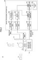
FIG. 2 is a drawing illustrating a functional configuration of theimage processing apparatus 100 according to the embodiment. As illustrated inFIG. 2 , theimaging system 10 further includes theimage processing apparatus 100. - As illustrated in
FIG. 2 , theimage processing apparatus 100 includes afirst acquisition unit 101, asecond acquisition unit 102, a position determiner 103, animage corrector 104, athird acquisition unit 105, acurrent distribution generator 106, an imagesuperimposing unit 107, and anoutput unit 108. - The
first acquisition unit 101 obtains a first radiation image (a radiation image of the subject S captured from a position below the subject S) captured by thefirst imager 13. - The
second acquisition unit 102 obtains a second radiation image (a radiation image of the subject S captured from a position lateral to the subject S) captured by thesecond imager 14. - The
position determiner 103 determines a position in the subject S at which magnetism is generated (an example of "information on a position of a specific region of a subject") relative to the imaging position of the first radiation image (i.e., an imaging position at which thefirst imager 13 captures an image) based on the second radiation image obtained by thesecond acquisition unit 102. In the present embodiment, theposition determiner 103 determines a height r2 at a vertical position H2 of the spinal cord S1 of the subject S relative to the imaging position of the first radiation image (i.e., a vertical position H1 of the first imager 13) (seeFIG. 4 ). - The
image corrector 104 corrects the first radiation image obtained by thefirst acquisition unit 101 based on the height r2 at the vertical position H2 of the spinal cord S1 of the subject S determined by theposition determiner 103. Specifically, theimage corrector 104 reduces the size of the first radiation image to a size corresponding to the vertical position H2 of the spinal cord S1 of the subject S determined by theposition determiner 103. The size corresponding to the vertical position H2 indicates a size that the first radiation image may have if the first radiation image is captured by thefirst imager 13 at the vertical position H2. Thus, "correction of the image by the image corrector" indicates reducing a radiation image. Any method may be used to reduce the size of the first radiation image. For example, as illustrated inFIG. 7 , the position of each pixel in the first radiation image after reduction may be calculated using a reduction coefficient. In this case, reduction coefficients applied to the respective pixels may be the same or may be different from each other. - The
third acquisition unit 105 obtains magnetism detection data (that is, the magnetism detection value at each of multiple positions in the subject S) output from themagnetism detection device 15. - The
current distribution generator 106 generates a current distribution image representing the current distribution in the target region of the subject S based on the magnetism detection data obtained by thethird acquisition unit 105. - The
image superimposing unit 107 generates a superimposed image in which the current distribution image generated by thecurrent distribution generator 106 and the first radiation image corrected by theimage corrector 104 are superimposed on each other. - The
output unit 108 outputs the superimposed image generated by theimage superimposing unit 107. For example, theoutput unit 108 displays the superimposed image on a display. However, the present invention is not limited to this example, and theoutput unit 108 may output the superimposed image with other output methods (for example, output to a memory or transmission to an external device). - The functional components of the
image processing apparatus 100 described above may be implemented by one or more processing circuits. In the present application, examples of "processing circuits" include a processor programmed to execute functions according to software such as a processor implemented by an electronic circuit; and devices such as an application specific integrated circuit (ASIC), a digital signal processor (DSP), a field programmable gate array (FPGA), and other circuit modules designed to execute the functions of theimage processing apparatus 100 described above. -
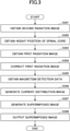
FIG. 3 is a flowchart illustrating a process performed by theimage processing apparatus 100 according to the embodiment. - First, the
second acquisition unit 102 obtains the second radiation image (i.e., a radiation image of the subject S captured from a position lateral to the subject S) captured by the second imager 14 (step S301). - Next, the
position determiner 103 determines the height r2 at the vertical position H2 of the spinal cord S1 of the subject S relative to the vertical position H1 of thefirst imager 13 based on the second radiation image obtained at step S301 (step S302). Specifically, for example, the height r2 may be determined by causing theoutput unit 108 to output the second radiation image on a display unit (not shown) and requesting an operator to specify (or locate) the position of the spinal cord S1 on a screen. Alternatively, theposition determiner 103 may be configured to recognize the spinal cord S1 by machine learning at theposition determiner 103 or using external machine learning and determine the height r2 based on the recognition result. - Next, the
first acquisition unit 101 obtains the first radiation image (i.e., a radiation image of the subject S captured from a position below the subject S) captured by the first imager 13 (step S303). - Next, the
image corrector 104 corrects the size of the first radiation image obtained at step S303 based on the height r2 at the vertical position H2 of the spinal cord S1 of the subject S determined at step S302 (step S304). Specifically, theimage corrector 104 reduces the size of the first radiation image to a size corresponding to the vertical position H2 based on the ratio between a distance R between thefirst radiation source 11 and thefirst imager 13 and a distance (R - r2) . - Next, the
third acquisition unit 105 obtains the magnetism detection data (that is, the magnetism detection value of each of the multiple positions in the subject S) output from the magnetism detection device 15 (step S305). - Next, the
current distribution generator 106 generates a current distribution image representing the current distribution in the target region of the subject S based on the magnetism detection data obtained at step S305 (step S306). - Next, the
image superimposing unit 107 generates a superimposed image by superimposing the current distribution image generated at step S306 and the first radiation image corrected at step S304 on each other (step S307). Next, theoutput unit 108 outputs the superimposed image generated at step S307 (step S308). Then, theimage processing apparatus 100 ends the process illustrated inFIG. 3 . - In the above process, the second radiation image is obtained first. However, the present invention is not limited to this example, and the first radiation image may be obtained first. Still, however, in the present embodiment, the second radiation image is preferably obtained first because the vertical position H2 of the spinal cord S1 of the subject S is determined based on the second radiation image. Also, in terms of preventing the misalignment due to the movement of the subject S, the first radiation image and the second radiation image are more preferably obtained substantially at the same time.
- Also, in terms of preventing the misalignment due to the movement of the subject S, the
imaging system 10 preferably includes two pairs of a radiation source and an imager. However, the present invention is not limited to this example, and theimaging system 10 may include, for example, one pair of a radiation source and an imager. In this case, theimaging system 10 may capture and obtain the first radiation image using the one pair of the radiation source and the imager as thefirst radiation source 11 and the first imager 13 (step S303), and capture and obtain the second radiation image by moving the one pair of the radiation source and the imager and using them as thesecond radiation source 12 and the second imager 14 (step S301). - Also, in terms of preventing the misalignment of radiation sources, the
imaging system 10 preferably includes two radiation sources that are fixed or have positional reproducibility. However, the present invention is not limited to this example, and theimaging system 10 may include, for example, one radiation source. In this case, theimaging system 10 may capture and obtain the first radiation image by irradiating the subject S using the one radiation source as the first radiation source 11 (step S303), and capture and obtain the second radiation image by moving the one radiation source and irradiating the subject S using the one radiation source as the second radiation source 12 (step S301) . - In addition, in terms of preventing the misalignment of imagers, the
imaging system 10 preferably includes two imagers that are fixed or have positional reproducibility. However, the present invention is not limited to this example, and theimaging system 10 may include, for example, one imager. In this case, theimaging system 10 may capture and obtain the first radiation image using the one imager as the first imager 13 (step S303), and capture and obtain the second radiation image by moving the one imager and using the one imager as the second imager 14 (step S301). - The above-described process is based on the assumption that either the radiation source or the imager is implemented by two devices. However, the first radiation image and the second radiation image may be captured and obtained by combining the above-described steps and moving one radiation source and one imager.
-
FIG. 4 is a schematic diagram illustrating the positional relationship between a horizontal position P1 of the spinal cord S1 of the subject S and an imaging position P2 of the second radiation image.FIG. 5 is a drawing illustrating an example of a second radiation image corrected by theposition determiner 103. - As illustrated in
FIG. 4 , the horizontal position P1 of the spinal cord S1 in the subject S is the central position in the horizontal direction of the subject S. On the other hand, the imaging position P2 at which the second radiation image is captured by thesecond imager 14, is located farther from thesecond radiation source 12 than the horizontal position P1 of the spinal cord S1. - As illustrated in
FIG. 4 , because thesecond radiation source 12 is a point radiation source, the irradiation range of thesecond radiation source 12 gradually increases as the distance from thesecond radiation source 12 increases. Therefore, the size of the second radiation image captured by thesecond imager 14 at the imaging position P2 is larger than the size of an image captured at the horizontal position P1 of the spinal cord S1. - For the above reason, the
position determiner 103 first identifies the horizontal position P1 of the spinal cord S1. For example, the subject S is placed on the bed such that the spinous process at the center of the spinal cord S1 in the horizontal direction is aligned with a linear marker provided in a predetermined position in the horizontal direction of the bed. Because the horizontal position P1 of the spinal cord S1 is aligned with the predetermined position in the horizontal direction of the bed, theposition determiner 103 can easily determine the horizontal position P1 of the spinal cord S1. As another example, the subject S may be placed on the bed after attaching a marker coil to the spinous process of the spinal cord S1. In this case, theposition determiner 103 can easily determine the horizontal position P1 of the spinal cord S1 based on the positional information of the marker coil. - Next, the
position determiner 103 reduces the size of the second radiation image captured by thesecond imager 14 at a reduction percentage corresponding to a distance r1 between the determined horizontal position P1 of the spinal cord S1 and the imaging position P2 so that the size of the second radiation image is reduced to a size corresponding to the horizontal position P1 of the spinal cord S1. The size corresponding to the horizontal position P1 indicates a size that the second radiation image may have if the second radiation image is captured by thesecond imager 14 at the horizontal position P1. Specifically, theposition determiner 103 stores (or inputs), in advance, information (corresponding to "positional information of a device that captures a radiation image") indicating the positional relationship between the position of thesecond radiation source 12 and the imaging position P2, and calculates the reduction percentage to be applied to the second radiation image based on the stored information and the information on the horizontal position P1 of the spinal cord S1. - Next, the
position determiner 103 determines the vertical position H2 of the spinal cord S1 in the corrected second radiation image. For example, theposition determiner 103 displays the corrected second radiation image on a display and requests an operator to specify the vertical position H2 of the spinal cord S1 in the corrected second radiation image. - Then, based on the specified vertical position H2 of the spinal cord S1 in the corrected second radiation image, the
position determiner 103 calculates the height r2 from the vertical position H1 to the vertical position H2. - Here, the size of each pixel in the corrected second radiation image becomes smaller than the size of each pixel in the second radiation image before correction according to the reduction percentage used for the correction of the second radiation image.
- For example, when the size of each pixel in the second radiation image before correction is "0.15 mm" and the reduction percentage used for the correction of the second radiation image is "80%", the size of each pixel in the corrected second radiation image becomes "0.12 mm" .
- Then, the
position determiner 103 calculates the height r2 from the vertical position H1 to the vertical position H2 by multiplying the size of each pixel in the second radiation image before correction by the number of pixels from the vertical position H1 to the vertical position H2 in the corrected second radiation image. - For example, when the size of each pixel in the corrected second radiation image is "0.12 mm" and the number of pixels from the vertical position H1 to the vertical position H2 in the corrected second radiation image is "650", the
position determiner 103 calculates the height r2 from the vertical position H1 to the vertical position H2 as "78 mm". - Here, depending on the positional relationship between the
second radiation source 12 and thesecond imager 14, the vertical position H1 may not be included in the second radiation image. In this case, it is preferable to provide a radiation marker whose positional relationship with the vertical position H1 is known at a position where the radiation marker is certainly captured in the second radiation image, and to determine the vertical position H1 based on the radiation marker. -
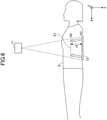
FIG. 6 is a schematic diagram illustrating the positional relationship between the vertical position H2 of the spinal cord S1 of the subject S and the vertical position H1 of thefirst imager 13. - As illustrated in
FIG. 6 , the vertical position H2 of the spinal cord S1 in the subject S is in the body of the subject S. On the other hand, the vertical position H1 of the first radiation image captured by thefirst imager 13 is outside of the body of the subject S and is located farther from thefirst radiation source 11 than the vertical position H2 of the spinal cord S1. - As illustrated in
FIG. 6 , because thefirst radiation source 11 is a point radiation source, the irradiation range of thefirst radiation source 11 gradually increases as the distance from thefirst radiation source 11 increases. For this reason, the size of the first radiation image captured by thefirst imager 13 at the vertical position H1 is greater than a size corresponding to the vertical position H2 of the spinal cord S1. Therefore, theimage corrector 104 corrects the first radiation image so that the size of the first radiation image is reduced to the size corresponding to the vertical position H2 of the spinal cord S1. -
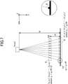
FIG. 7 is a drawing illustrating an example of a method of correcting the first radiation image by theimage corrector 104. InFIG. 7 , for description purposes, the spinal cord S1 of the subject S at the vertical position H2 is represented by a set of n black dots. Also, inFIG. 7 , a first radiation image S' captured by thefirst imager 13 at the vertical position H1 using the radiation emitted from thefirst radiation source 11 toward the subject S is similarly represented by a set of n black dots. Further, inFIG. 7 , the direction in which the radiation is emitted from thefirst radiation source 11 is defined as the Y axis, and the direction orthogonal to the Y axis is defined as the X axis. - Here, referring to a black dot x'1 in the first radiation image S', an angle θ formed between the radiation emitted from the
first radiation source 11 and thefirst imager 13 at the black dot x'1 is expressed by θ = arctan (R / (x'1 - x0). Here, R is a known distance from thefirst radiation source 11 to thefirst imager 13, and x0 is the position of thefirst radiation source 11 on the X axis. Accordingly, the relationship between a black dot x1 in the subject S and the black dot x'1 in the first radiation image S' is represented by (x1 - x'1) tan θ = r2, which can be deformed into x1 = r2 / tan θ + x'1. Here, r2 is the height from the vertical position H1 to the vertical position H2, which has already been determined by theposition determiner 103. - The
image corrector 104 obtains the position at the vertical position H2 of the subject S for each of pixels constituting the first radiation image S' in a similar manner and thereby corrects the first radiation image S' to a size corresponding to the vertical position H2 of the subject S. -
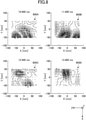
FIG. 8 is a drawing illustrating examples of current distribution images generated by thecurrent distribution generator 106.
Current distribution images FIG. 8 represent time transition of the current distribution of neural activity currents in a target region (in this example, the lumbar region) of the subject S and are generated by thecurrent distribution generator 106 based on magnetism detection data output from themagnetism detection device 15. InFIG. 8 , the time (10.400 ms, 11.400 ms, 12.400 ms, or 13.400 ms) elapsed from the timing when electrical stimulation was given to the subject S (particularly, a fibular nerve in a fibular head in this example) is indicated in each of thecurrent distribution images current distribution images -
FIG. 9 is a drawing illustrating examples of superimposed images generated by theimage superimposing unit 107. Each of superimposedimages FIG. 9 is generated by theimage superimposing unit 107 by superimposing the corresponding one of thecurrent distribution images FIG. 8 on the first radiation image (a radiation image of a target region (in this example, the lumbar region) of the subject S) corrected by theimage corrector 104. Accordingly, each of the superimposedimages 900A through 900D includes both of the image of a spine S1' of the subject S represented by the first radiation image and the current distribution around the spine S1' represented by the corresponding one of thecurrent distribution images 800A through 800D. In the example illustrated inFIG. 9 , to facilitate the understanding, the outline of the spine S1' in the first radiation image in thesuperimposed image 900A is emphasized. - Here, the first radiation image used for each of the superimposed
images 900A through 900D is corrected by theimage corrector 104 to have a size corresponding to the vertical position H2 of the spine S1' of the subject S. Also, thecurrent distribution images 800A through 800D used for the superimposedimages 900A through 900D are generated by thecurrent distribution generator 106 to have a size corresponding to the vertical position H2 of the spine S1'. - That is, both of the first radiation image and the
current distribution images 800A through 800D used to generate the superimposedimages 900A through 900D have a size corresponding to the same vertical position (vertical position H2). Therefore, in the superimposedimages 900A through 900D, both the image of the spine S1' of the subject S represented by the first radiation image and the current distributions around the spine S1' represented by thecurrent distribution images 800A through 800D are presented with high positional accuracy. -
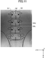
FIGs. 10 and11 are drawings for explaining a variation of the method of correcting the first radiation image by theimage corrector 104.FIG. 10 illustrates physical features depicted in the second radiation image.FIG. 11 illustrates physical features depicted in the first radiation image. In the example illustrated inFIGs. 10 and11 , the outline of the spine S1' in each of the first radiation image and the second radiation image is emphasized to facilitate the understanding. Also, in the example illustrated inFIG. 10 and11 , the imaging range of the first radiation image illustrated inFIG. 11 is greater than the imaging range of the second radiation image illustrated inFIG. 10 . - In the example illustrated in
FIGs. 10 and11 , the lower ends of pedicles of vertebral arch S2 in the spine S1', an upper end S3U of the spinous process, and a lower end S3L of the spinous process are used as the feature points extracted by theimage corrector 104. In the example illustrated inFIGs. 10 and11 , each of the lower ends of the pedicles of vertebral arch S2 is marked with an "x". - When the positional relationship between the
first radiation source 11 and thefirst imager 13 is unknown, as illustrated inFIGs. 10 and11 , theimage corrector 104 may extract common physical features from the first radiation image and the second radiation image as another example of "information on a position of a specific region of a subject", and may correct the size of the first radiation image based on the positional relationship (e.g., the ratio of distances between multiple physical features) between the position of a physical feature in the first radiation image and the position of a physical feature in the second radiation image. - The
image corrector 104 can extract the positions of multiple physical features in the standing height direction (the X-axis direction) of the subject S from each of the first radiation image and the second radiation image, and therefore can correct the first radiation image in the standing height direction (the X-axis direction) of the subject S using a correction coefficient obtained from the multiple physical features. On the other hand, theimage corrector 104 cannot extract the positions of multiple physical features in the width direction (the Z-axis direction) of the subject S from the second radiation image. Therefore, theimage corrector 104 may be configured to correct the first radiation image in the width direction (the Z-axis direction) of the subject S using the same correction coefficient as that used for the correction of the first radiation image in the vertical direction. - An aspect of this disclosure makes it possible to easily correct a radiation image according to the position of a specific region in the body of a subject.
- An image processing apparatus, an imaging system, an image processing method, and a storage medium according to an embodiment of the present invention are described above. However, the present invention is not limited to the specifically disclosed embodiment, and variations and modifications may be made without departing from the scope of the present invention.
Claims (10)
- An image processing apparatus, comprising:a first acquisition unit configured to obtain a first radiation image of a subject captured from a first direction;a second acquisition unit configured to obtain a second radiation image of the subject captured from a second direction that intersects the first direction; andan image corrector configured tocorrect one of the first radiation image and the second radiation image based on positional information of a device for capturing the one of the first radiation image and the second radiation image, orcorrect another one of the first radiation image and the second radiation image based on information on a position of a specific region of the subject obtained from the one of the first radiation image and the second radiation image.
- The image processing apparatus as claimed in claim 1, further comprising:a position determiner configured to determine a position of a magnetism generating part of the subject in the one of the first radiation image and the second radiation image, whereinthe image corrector is configured to correct the another one of the first radiation image and the second radiation image to a size corresponding to the position of the magnetism generating part determined by the position determiner based on the position of the magnetism generating part, the position of the magnetism generating part being the information on the position of the specific region of the subject.
- The image processing apparatus as claimed in claim 2, wherein
the image corrector is configured to correct the another one of the first radiation image and the second radiation image to the size corresponding to the position of the magnetism generating part based on a distance between the position of the magnetism generating part and an imaging position of the another one of the first radiation image and the second radiation image. - The image processing apparatus as claimed in claim 1, wherein the image corrector is configured toextract a physical feature, which is included in both of the first radiation image and the second radiation image, from the first radiation image and the second radiation image, andcorrect the another one of the first radiation image and the second radiation image to a size corresponding to a position of a magnetism generating part of the subject based on a positional relationship between a position of the physical feature in the one of the first radiation image and the second radiation image and a position of the physical feature in the another one of the first radiation image and the second radiation image.
- The image processing apparatus as claimed in any one of claims 2 through 4, further comprising:a third acquisition unit configured to obtain magnetism detection data from a magnetism detection device that detects magnetism emitted by the magnetism generating part;a current distribution generator configured to generate a current distribution image representing current distribution in the subject based on the magnetism detection data; andan image superimposing unit configured to generate a superimposed image by superimposing the current distribution image generated by the current distribution generator on the another one of the first radiation image and the second radiation image corrected by the image corrector.
- The image processing apparatus as claimed in any one of claims 2 through 5, wherein the magnetism generating part is a spinal cord or a cauda equina nerve of the subject.
- The image processing apparatus as claimed in any one of claims 1 through 6, wherein
the first direction is a front direction or a back direction of the subject; and
the second direction is a right-side direction or a left-side side direction of the subject. - An imaging system, comprising:the image processing apparatus as claimed in any one of claims 1 through 7;at least one imaging device configured to capture the first radiation image and the second radiation image; andat least one radiation source configured to irradiate the subject with radiation when the first radiation image and the second radiation image are captured.
- An image processing method, comprising:obtaining a first radiation image of a subject captured from a first direction;obtaining a second radiation image of the subject captured from a second direction that intersects the first direction; andeither correcting one of the first radiation image and the second radiation image based on positional information of a device for capturing the one of the first radiation image and the second radiation image, or correcting another one of the first radiation image and the second radiation image based on information on a position of a specific region of the subject obtained from the one of the first radiation image and the second radiation image.
- A non-transitory computer-readable storage medium storing a program for causing a computer to execute a process, the process including:obtaining a first radiation image of a subject captured from a first direction;obtaining a second radiation image of the subject captured from a second direction that intersects the first direction; andeither correcting one of the first radiation image and the second radiation image based on positional information of a device for capturing the one of the first radiation image and the second radiation image, or correcting another one of the first radiation image and the second radiation image based on information on a position of a specific region of the subject obtained from the one of the first radiation image and the second radiation image.
Applications Claiming Priority (2)
| Application Number | Priority Date | Filing Date | Title |
|---|---|---|---|
| JP2020131129 | 2020-07-31 | ||
| JP2021044354A JP7511845B2 (en) | 2020-07-31 | 2021-03-18 | IMAGE PROCESSING APPARATUS, IMAGE PICKUP SYSTEM, IMAGE PROCESSING METHOD, AND PROGRAM |
Publications (2)
| Publication Number | Publication Date |
|---|---|
| EP3944816A1 true EP3944816A1 (en) | 2022-02-02 |
| EP3944816B1 EP3944816B1 (en) | 2023-12-20 |
Family
ID=77021106
Family Applications (1)
| Application Number | Title | Priority Date | Filing Date |
|---|---|---|---|
| EP21186878.1A Active EP3944816B1 (en) | 2020-07-31 | 2021-07-21 | Image processing apparatus, imaging system, image processing method, and storage medium |
Country Status (3)
| Country | Link |
|---|---|
| US (1) | US11980493B2 (en) |
| EP (1) | EP3944816B1 (en) |
| CN (1) | CN114071033B (en) |
Families Citing this family (2)
| Publication number | Priority date | Publication date | Assignee | Title |
|---|---|---|---|---|
| JP2023142080A (en) * | 2022-03-24 | 2023-10-05 | アイシンシロキ株式会社 | Object detection method and detection device |
| JP2024024505A (en) | 2022-08-09 | 2024-02-22 | 株式会社リコー | Biometric device, biometric system, and biometric method |
Citations (5)
| Publication number | Priority date | Publication date | Assignee | Title |
|---|---|---|---|---|
| JPH0213798B2 (en) | 1980-06-24 | 1990-04-05 | Nintendo Co Ltd | |
| US20050195945A1 (en) * | 2004-03-05 | 2005-09-08 | Atsushi Gotoh | X-ray diagnostic apparatus |
| US20110069812A1 (en) * | 2009-09-24 | 2011-03-24 | Fujifilm Corporation | Radiation imaging apparatus |
| US20160296195A1 (en) * | 2015-04-09 | 2016-10-13 | Kabushiki Kaisha Toshiba | X-ray diagnostic apparatus, and method of adjusting irradiation range of x-ray diagnostic apparatus |
| JP2018011952A (en) * | 2016-07-08 | 2018-01-25 | 株式会社リコー | Diagnosis support system, diagnosis support apparatus, and diagnosis support program |
Family Cites Families (22)
| Publication number | Priority date | Publication date | Assignee | Title |
|---|---|---|---|---|
| JP4110108B2 (en) * | 2004-03-26 | 2008-07-02 | 株式会社日立ハイテクノロジーズ | Biomagnetic field measurement device, horizontal position setting method for biomagnetic field measurement |
| GB0913930D0 (en) * | 2009-08-07 | 2009-09-16 | Ucl Business Plc | Apparatus and method for registering two medical images |
| JP2012152480A (en) * | 2011-01-28 | 2012-08-16 | Fujifilm Corp | Radiation image display device and method |
| US8848868B2 (en) * | 2011-08-24 | 2014-09-30 | Albert Davydov | X-ray system and method of using thereof |
| JP5485308B2 (en) * | 2012-01-27 | 2014-05-07 | 富士フイルム株式会社 | Radiographic imaging apparatus, radiographic imaging method and program |
| JP6076658B2 (en) | 2012-09-14 | 2017-02-08 | 東芝メディカルシステムズ株式会社 | Medical image processing apparatus, X-ray diagnostic apparatus, and medical image processing program |
| JP5839710B2 (en) * | 2012-09-27 | 2016-01-06 | 富士フイルム株式会社 | Analysis point setting device and method, and body motion detection device and method |
| JP2016019724A (en) * | 2014-06-19 | 2016-02-04 | 株式会社東芝 | X-ray diagnostic equipment |
| CN106793983B (en) * | 2014-10-03 | 2019-12-03 | 株式会社岛津制作所 | X-ray camera |
| JP6072102B2 (en) * | 2015-01-30 | 2017-02-01 | キヤノン株式会社 | Radiographic system and radiographic method |
| KR20160103518A (en) * | 2015-02-24 | 2016-09-01 | 삼성전자주식회사 | Medical image processing apparatus and method for the same |
| JP6513798B2 (en) | 2015-04-30 | 2019-05-15 | 国立大学法人 東京医科歯科大学 | Biological information measuring device |
| US11191506B2 (en) * | 2016-07-08 | 2021-12-07 | Ricoh Company, Ltd. | Diagnosis support system, diagnosis support apparatus, and recording medium |
| EP3520698B1 (en) * | 2016-09-30 | 2022-12-14 | National University Corporation Tokyo Medical and Dental University | Biometric information measuring device |
| US11138746B2 (en) * | 2017-07-03 | 2021-10-05 | Ricoh Company, Ltd. | Diagnostic support system and diagnostic support method |
| JP7176689B2 (en) | 2017-12-01 | 2022-11-22 | 株式会社リコー | Biomagnetism measuring device and biomagnetism measuring method |
| US11375934B2 (en) | 2017-12-01 | 2022-07-05 | Ricoh Company, Ltd. | Biomagnetic measurement apparatus, biological information measurement apparatus, and biomagnetic measurement method |
| KR102204515B1 (en) * | 2018-08-31 | 2021-01-20 | (주) 뉴케어 | x-ray imaging method using variable imaging plane projection and x-ray imaging device applying the same |
| JP7167564B2 (en) * | 2018-09-05 | 2022-11-09 | 株式会社島津製作所 | Radiographic device and method of operating the radiographic device |
| JP7234709B2 (en) * | 2019-03-13 | 2023-03-08 | 株式会社島津製作所 | radiography equipment |
| JP7358866B2 (en) | 2019-06-27 | 2023-10-11 | 株式会社リコー | Radiation source position estimation system, calibration system, and biomagnetic measurement system |
| US12102470B2 (en) | 2019-06-27 | 2024-10-01 | Ricoh Company, Ltd. | Radiation source position estimation system, calibration system and biomagnetic measuring system |
-
2021
- 2021-07-16 US US17/305,890 patent/US11980493B2/en active Active
- 2021-07-21 EP EP21186878.1A patent/EP3944816B1/en active Active
- 2021-07-29 CN CN202110861964.5A patent/CN114071033B/en active Active
Patent Citations (5)
| Publication number | Priority date | Publication date | Assignee | Title |
|---|---|---|---|---|
| JPH0213798B2 (en) | 1980-06-24 | 1990-04-05 | Nintendo Co Ltd | |
| US20050195945A1 (en) * | 2004-03-05 | 2005-09-08 | Atsushi Gotoh | X-ray diagnostic apparatus |
| US20110069812A1 (en) * | 2009-09-24 | 2011-03-24 | Fujifilm Corporation | Radiation imaging apparatus |
| US20160296195A1 (en) * | 2015-04-09 | 2016-10-13 | Kabushiki Kaisha Toshiba | X-ray diagnostic apparatus, and method of adjusting irradiation range of x-ray diagnostic apparatus |
| JP2018011952A (en) * | 2016-07-08 | 2018-01-25 | 株式会社リコー | Diagnosis support system, diagnosis support apparatus, and diagnosis support program |
Non-Patent Citations (2)
| Title |
|---|
| CLOSE R ET AL: "AUTOMATIC CORRECTION OF BIPLANE PROJECTION IMAGING GEOMETRY", MEDICAL PHYSICS, AIP, MELVILLE, NY, US, vol. 23, no. 1, 1 January 1996 (1996-01-01), pages 133 - 139, XP000554242, ISSN: 0094-2405, DOI: 10.1118/1.597789 * |
| SATOSHI SUMIYA ET AL: "Magnetospinography visualizes electrophysiological activity in the cervical spinal cord", SCIENTIFIC REPORTS, vol. 7, no. 1, 19 May 2017 (2017-05-19), XP055449754, DOI: 10.1038/s41598-017-02406-8 * |
Also Published As
| Publication number | Publication date |
|---|---|
| CN114071033A (en) | 2022-02-18 |
| EP3944816B1 (en) | 2023-12-20 |
| US20220031276A1 (en) | 2022-02-03 |
| US11980493B2 (en) | 2024-05-14 |
| CN114071033B (en) | 2024-08-23 |
Similar Documents
| Publication | Publication Date | Title |
|---|---|---|
| JP6833444B2 (en) | Radiation equipment, radiography system, radiography method, and program | |
| US9462733B2 (en) | Magnetic shielding apparatus and magnetic shielding method | |
| EP3944816B1 (en) | Image processing apparatus, imaging system, image processing method, and storage medium | |
| US20220237817A1 (en) | Systems and methods for artificial intelligence based image analysis for placement of surgical appliance | |
| US11051778B2 (en) | X-ray fluoroscopic imaging apparatus | |
| US20190209871A1 (en) | A Realtime radiotherapy markerless calibration and measurement system | |
| Durdle et al. | An improved structured light technique for surface reconstruction of the human trunk | |
| US20160247293A1 (en) | Medical imaging systems and methods for performing motion-corrected image reconstruction | |
| CN116205954A (en) | Method and system for image registration | |
| US10657661B2 (en) | Information processing apparatus, imaging system, information processing method, and program causing computer to execute information processing | |
| JPH07181609A (en) | Region of irradiation field extracting device for radiograph | |
| JP7511845B2 (en) | IMAGE PROCESSING APPARATUS, IMAGE PICKUP SYSTEM, IMAGE PROCESSING METHOD, AND PROGRAM | |
| US20080123929A1 (en) | Apparatus, method and program for image type judgment | |
| US11426139B2 (en) | Radiographic imaging apparatus | |
| US11439336B2 (en) | Biological information measurement system and recording medium | |
| US10176587B2 (en) | Medical cross-sectional image displaying apparatus and method for displaying cross-sectional image | |
| JP5635389B2 (en) | Image processing apparatus, image processing program, and X-ray diagnostic imaging apparatus | |
| CN115486859B (en) | Medical image processing device and medical image processing method | |
| US20090296883A1 (en) | Radiation image correction apparatus, method, and program | |
| KR101818183B1 (en) | Method for correcting distortion of fluoroscopy image | |
| CN112996440B (en) | X-ray imaging device | |
| CN106600575A (en) | Stitched image verification method and device, X-ray photography system | |
| CN115280362A (en) | Tracking method | |
| US20250275724A1 (en) | Examination table movement control device, examination table movement control method, program, and medical image capturing apparatus | |
| JP7740420B1 (en) | Radiography support device, radiation photography support system, radiation photography support method and program |
Legal Events
| Date | Code | Title | Description |
|---|---|---|---|
| PUAI | Public reference made under article 153(3) epc to a published international application that has entered the european phase |
Free format text: ORIGINAL CODE: 0009012 |
|
| STAA | Information on the status of an ep patent application or granted ep patent |
Free format text: STATUS: REQUEST FOR EXAMINATION WAS MADE |
|
| 17P | Request for examination filed |
Effective date: 20210721 |
|
| AK | Designated contracting states |
Kind code of ref document: A1 Designated state(s): AL AT BE BG CH CY CZ DE DK EE ES FI FR GB GR HR HU IE IS IT LI LT LU LV MC MK MT NL NO PL PT RO RS SE SI SK SM TR |
|
| GRAP | Despatch of communication of intention to grant a patent |
Free format text: ORIGINAL CODE: EPIDOSNIGR1 |
|
| STAA | Information on the status of an ep patent application or granted ep patent |
Free format text: STATUS: GRANT OF PATENT IS INTENDED |
|
| RIC1 | Information provided on ipc code assigned before grant |
Ipc: A61B 5/00 20060101ALN20230706BHEP Ipc: A61B 5/242 20210101ALI20230706BHEP Ipc: G06T 3/00 20060101ALI20230706BHEP Ipc: A61B 6/00 20060101AFI20230706BHEP |
|
| INTG | Intention to grant announced |
Effective date: 20230725 |
|
| P01 | Opt-out of the competence of the unified patent court (upc) registered |
Effective date: 20230922 |
|
| GRAS | Grant fee paid |
Free format text: ORIGINAL CODE: EPIDOSNIGR3 |
|
| GRAA | (expected) grant |
Free format text: ORIGINAL CODE: 0009210 |
|
| STAA | Information on the status of an ep patent application or granted ep patent |
Free format text: STATUS: THE PATENT HAS BEEN GRANTED |
|
| AK | Designated contracting states |
Kind code of ref document: B1 Designated state(s): AL AT BE BG CH CY CZ DE DK EE ES FI FR GB GR HR HU IE IS IT LI LT LU LV MC MK MT NL NO PL PT RO RS SE SI SK SM TR |
|
| REG | Reference to a national code |
Ref country code: GB Ref legal event code: FG4D |
|
| REG | Reference to a national code |
Ref country code: CH Ref legal event code: EP |
|
| REG | Reference to a national code |
Ref country code: DE Ref legal event code: R096 Ref document number: 602021007832 Country of ref document: DE |
|
| REG | Reference to a national code |
Ref country code: IE Ref legal event code: FG4D |
|
| PG25 | Lapsed in a contracting state [announced via postgrant information from national office to epo] |
Ref country code: GR Free format text: LAPSE BECAUSE OF FAILURE TO SUBMIT A TRANSLATION OF THE DESCRIPTION OR TO PAY THE FEE WITHIN THE PRESCRIBED TIME-LIMIT Effective date: 20240321 |
|
| REG | Reference to a national code |
Ref country code: LT Ref legal event code: MG9D |
|
| PG25 | Lapsed in a contracting state [announced via postgrant information from national office to epo] |
Ref country code: LT Free format text: LAPSE BECAUSE OF FAILURE TO SUBMIT A TRANSLATION OF THE DESCRIPTION OR TO PAY THE FEE WITHIN THE PRESCRIBED TIME-LIMIT Effective date: 20231220 |
|
| REG | Reference to a national code |
Ref country code: NL Ref legal event code: MP Effective date: 20231220 |
|
| PG25 | Lapsed in a contracting state [announced via postgrant information from national office to epo] |
Ref country code: ES Free format text: LAPSE BECAUSE OF FAILURE TO SUBMIT A TRANSLATION OF THE DESCRIPTION OR TO PAY THE FEE WITHIN THE PRESCRIBED TIME-LIMIT Effective date: 20231220 |
|
| PG25 | Lapsed in a contracting state [announced via postgrant information from national office to epo] |
Ref country code: LT Free format text: LAPSE BECAUSE OF FAILURE TO SUBMIT A TRANSLATION OF THE DESCRIPTION OR TO PAY THE FEE WITHIN THE PRESCRIBED TIME-LIMIT Effective date: 20231220 Ref country code: GR Free format text: LAPSE BECAUSE OF FAILURE TO SUBMIT A TRANSLATION OF THE DESCRIPTION OR TO PAY THE FEE WITHIN THE PRESCRIBED TIME-LIMIT Effective date: 20240321 Ref country code: FI Free format text: LAPSE BECAUSE OF FAILURE TO SUBMIT A TRANSLATION OF THE DESCRIPTION OR TO PAY THE FEE WITHIN THE PRESCRIBED TIME-LIMIT Effective date: 20231220 Ref country code: ES Free format text: LAPSE BECAUSE OF FAILURE TO SUBMIT A TRANSLATION OF THE DESCRIPTION OR TO PAY THE FEE WITHIN THE PRESCRIBED TIME-LIMIT Effective date: 20231220 Ref country code: BG Free format text: LAPSE BECAUSE OF FAILURE TO SUBMIT A TRANSLATION OF THE DESCRIPTION OR TO PAY THE FEE WITHIN THE PRESCRIBED TIME-LIMIT Effective date: 20240320 |
|
| REG | Reference to a national code |
Ref country code: AT Ref legal event code: MK05 Ref document number: 1641763 Country of ref document: AT Kind code of ref document: T Effective date: 20231220 |
|
| PG25 | Lapsed in a contracting state [announced via postgrant information from national office to epo] |
Ref country code: NL Free format text: LAPSE BECAUSE OF FAILURE TO SUBMIT A TRANSLATION OF THE DESCRIPTION OR TO PAY THE FEE WITHIN THE PRESCRIBED TIME-LIMIT Effective date: 20231220 |
|
| PG25 | Lapsed in a contracting state [announced via postgrant information from national office to epo] |
Ref country code: SE Free format text: LAPSE BECAUSE OF FAILURE TO SUBMIT A TRANSLATION OF THE DESCRIPTION OR TO PAY THE FEE WITHIN THE PRESCRIBED TIME-LIMIT Effective date: 20231220 Ref country code: RS Free format text: LAPSE BECAUSE OF FAILURE TO SUBMIT A TRANSLATION OF THE DESCRIPTION OR TO PAY THE FEE WITHIN THE PRESCRIBED TIME-LIMIT Effective date: 20231220 Ref country code: NO Free format text: LAPSE BECAUSE OF FAILURE TO SUBMIT A TRANSLATION OF THE DESCRIPTION OR TO PAY THE FEE WITHIN THE PRESCRIBED TIME-LIMIT Effective date: 20240320 Ref country code: NL Free format text: LAPSE BECAUSE OF FAILURE TO SUBMIT A TRANSLATION OF THE DESCRIPTION OR TO PAY THE FEE WITHIN THE PRESCRIBED TIME-LIMIT Effective date: 20231220 Ref country code: LV Free format text: LAPSE BECAUSE OF FAILURE TO SUBMIT A TRANSLATION OF THE DESCRIPTION OR TO PAY THE FEE WITHIN THE PRESCRIBED TIME-LIMIT Effective date: 20231220 Ref country code: HR Free format text: LAPSE BECAUSE OF FAILURE TO SUBMIT A TRANSLATION OF THE DESCRIPTION OR TO PAY THE FEE WITHIN THE PRESCRIBED TIME-LIMIT Effective date: 20231220 |
|
| PG25 | Lapsed in a contracting state [announced via postgrant information from national office to epo] |
Ref country code: IS Free format text: LAPSE BECAUSE OF FAILURE TO SUBMIT A TRANSLATION OF THE DESCRIPTION OR TO PAY THE FEE WITHIN THE PRESCRIBED TIME-LIMIT Effective date: 20240420 |
|
| PG25 | Lapsed in a contracting state [announced via postgrant information from national office to epo] |
Ref country code: CZ Free format text: LAPSE BECAUSE OF FAILURE TO SUBMIT A TRANSLATION OF THE DESCRIPTION OR TO PAY THE FEE WITHIN THE PRESCRIBED TIME-LIMIT Effective date: 20231220 Ref country code: AT Free format text: LAPSE BECAUSE OF FAILURE TO SUBMIT A TRANSLATION OF THE DESCRIPTION OR TO PAY THE FEE WITHIN THE PRESCRIBED TIME-LIMIT Effective date: 20231220 |
|
| PG25 | Lapsed in a contracting state [announced via postgrant information from national office to epo] |
Ref country code: SK Free format text: LAPSE BECAUSE OF FAILURE TO SUBMIT A TRANSLATION OF THE DESCRIPTION OR TO PAY THE FEE WITHIN THE PRESCRIBED TIME-LIMIT Effective date: 20231220 |
|
| PG25 | Lapsed in a contracting state [announced via postgrant information from national office to epo] |
Ref country code: SM Free format text: LAPSE BECAUSE OF FAILURE TO SUBMIT A TRANSLATION OF THE DESCRIPTION OR TO PAY THE FEE WITHIN THE PRESCRIBED TIME-LIMIT Effective date: 20231220 Ref country code: SK Free format text: LAPSE BECAUSE OF FAILURE TO SUBMIT A TRANSLATION OF THE DESCRIPTION OR TO PAY THE FEE WITHIN THE PRESCRIBED TIME-LIMIT Effective date: 20231220 Ref country code: RO Free format text: LAPSE BECAUSE OF FAILURE TO SUBMIT A TRANSLATION OF THE DESCRIPTION OR TO PAY THE FEE WITHIN THE PRESCRIBED TIME-LIMIT Effective date: 20231220 Ref country code: IT Free format text: LAPSE BECAUSE OF FAILURE TO SUBMIT A TRANSLATION OF THE DESCRIPTION OR TO PAY THE FEE WITHIN THE PRESCRIBED TIME-LIMIT Effective date: 20231220 Ref country code: IS Free format text: LAPSE BECAUSE OF FAILURE TO SUBMIT A TRANSLATION OF THE DESCRIPTION OR TO PAY THE FEE WITHIN THE PRESCRIBED TIME-LIMIT Effective date: 20240420 Ref country code: EE Free format text: LAPSE BECAUSE OF FAILURE TO SUBMIT A TRANSLATION OF THE DESCRIPTION OR TO PAY THE FEE WITHIN THE PRESCRIBED TIME-LIMIT Effective date: 20231220 Ref country code: CZ Free format text: LAPSE BECAUSE OF FAILURE TO SUBMIT A TRANSLATION OF THE DESCRIPTION OR TO PAY THE FEE WITHIN THE PRESCRIBED TIME-LIMIT Effective date: 20231220 Ref country code: AT Free format text: LAPSE BECAUSE OF FAILURE TO SUBMIT A TRANSLATION OF THE DESCRIPTION OR TO PAY THE FEE WITHIN THE PRESCRIBED TIME-LIMIT Effective date: 20231220 |
|
| PG25 | Lapsed in a contracting state [announced via postgrant information from national office to epo] |
Ref country code: PL Free format text: LAPSE BECAUSE OF FAILURE TO SUBMIT A TRANSLATION OF THE DESCRIPTION OR TO PAY THE FEE WITHIN THE PRESCRIBED TIME-LIMIT Effective date: 20231220 Ref country code: PT Free format text: LAPSE BECAUSE OF FAILURE TO SUBMIT A TRANSLATION OF THE DESCRIPTION OR TO PAY THE FEE WITHIN THE PRESCRIBED TIME-LIMIT Effective date: 20240422 |
|
| PG25 | Lapsed in a contracting state [announced via postgrant information from national office to epo] |
Ref country code: PT Free format text: LAPSE BECAUSE OF FAILURE TO SUBMIT A TRANSLATION OF THE DESCRIPTION OR TO PAY THE FEE WITHIN THE PRESCRIBED TIME-LIMIT Effective date: 20240422 Ref country code: PL Free format text: LAPSE BECAUSE OF FAILURE TO SUBMIT A TRANSLATION OF THE DESCRIPTION OR TO PAY THE FEE WITHIN THE PRESCRIBED TIME-LIMIT Effective date: 20231220 |
|
| REG | Reference to a national code |
Ref country code: DE Ref legal event code: R097 Ref document number: 602021007832 Country of ref document: DE |
|
| PG25 | Lapsed in a contracting state [announced via postgrant information from national office to epo] |
Ref country code: DK Free format text: LAPSE BECAUSE OF FAILURE TO SUBMIT A TRANSLATION OF THE DESCRIPTION OR TO PAY THE FEE WITHIN THE PRESCRIBED TIME-LIMIT Effective date: 20231220 |
|
| PLBE | No opposition filed within time limit |
Free format text: ORIGINAL CODE: 0009261 |
|
| STAA | Information on the status of an ep patent application or granted ep patent |
Free format text: STATUS: NO OPPOSITION FILED WITHIN TIME LIMIT |
|
| PG25 | Lapsed in a contracting state [announced via postgrant information from national office to epo] |
Ref country code: SI Free format text: LAPSE BECAUSE OF FAILURE TO SUBMIT A TRANSLATION OF THE DESCRIPTION OR TO PAY THE FEE WITHIN THE PRESCRIBED TIME-LIMIT Effective date: 20231220 |
|
| PG25 | Lapsed in a contracting state [announced via postgrant information from national office to epo] |
Ref country code: SI Free format text: LAPSE BECAUSE OF FAILURE TO SUBMIT A TRANSLATION OF THE DESCRIPTION OR TO PAY THE FEE WITHIN THE PRESCRIBED TIME-LIMIT Effective date: 20231220 Ref country code: DK Free format text: LAPSE BECAUSE OF FAILURE TO SUBMIT A TRANSLATION OF THE DESCRIPTION OR TO PAY THE FEE WITHIN THE PRESCRIBED TIME-LIMIT Effective date: 20231220 |
|
| 26N | No opposition filed |
Effective date: 20240923 |
|
| PG25 | Lapsed in a contracting state [announced via postgrant information from national office to epo] |
Ref country code: MC Free format text: LAPSE BECAUSE OF FAILURE TO SUBMIT A TRANSLATION OF THE DESCRIPTION OR TO PAY THE FEE WITHIN THE PRESCRIBED TIME-LIMIT Effective date: 20231220 |
|
| REG | Reference to a national code |
Ref country code: GB Ref legal event code: 732E Free format text: REGISTERED BETWEEN 20250123 AND 20250128 |
|
| REG | Reference to a national code |
Ref country code: CH Ref legal event code: PL |
|
| REG | Reference to a national code |
Ref country code: DE Ref legal event code: R081 Ref document number: 602021007832 Country of ref document: DE Owner name: INSTITUTE OF SCIENCE TOKYO, JP Free format text: FORMER OWNERS: INSTITUTE OF SCIENCE TOKYO, TOKYO, JP; RICOH COMPANY, LTD., TOKYO, JP Ref country code: DE Ref legal event code: R081 Ref document number: 602021007832 Country of ref document: DE Owner name: INSTITUTE OF SCIENCE TOKYO, JP Free format text: FORMER OWNERS: NATIONAL UNIVERSITY CORPORATION TOKYO MEDICAL AND DENTAL UNIVERSITY, TOKYO, JP; RICOH COMPANY, LTD., TOKYO, JP |
|
| PG25 | Lapsed in a contracting state [announced via postgrant information from national office to epo] |
Ref country code: LU Free format text: LAPSE BECAUSE OF NON-PAYMENT OF DUE FEES Effective date: 20240721 |
|
| PG25 | Lapsed in a contracting state [announced via postgrant information from national office to epo] |
Ref country code: LU Free format text: LAPSE BECAUSE OF NON-PAYMENT OF DUE FEES Effective date: 20240721 |
|
| PG25 | Lapsed in a contracting state [announced via postgrant information from national office to epo] |
Ref country code: CH Free format text: LAPSE BECAUSE OF NON-PAYMENT OF DUE FEES Effective date: 20240731 Ref country code: BE Free format text: LAPSE BECAUSE OF NON-PAYMENT OF DUE FEES Effective date: 20240731 |
|
| REG | Reference to a national code |
Ref country code: BE Ref legal event code: MM Effective date: 20240731 |
|
| PG25 | Lapsed in a contracting state [announced via postgrant information from national office to epo] |
Ref country code: IE Free format text: LAPSE BECAUSE OF NON-PAYMENT OF DUE FEES Effective date: 20240721 |
|
| PGFP | Annual fee paid to national office [announced via postgrant information from national office to epo] |
Ref country code: DE Payment date: 20250708 Year of fee payment: 5 |
|
| PGFP | Annual fee paid to national office [announced via postgrant information from national office to epo] |
Ref country code: GB Payment date: 20250710 Year of fee payment: 5 |
|
| PGFP | Annual fee paid to national office [announced via postgrant information from national office to epo] |
Ref country code: FR Payment date: 20250708 Year of fee payment: 5 |
|
| PG25 | Lapsed in a contracting state [announced via postgrant information from national office to epo] |
Ref country code: CY Free format text: LAPSE BECAUSE OF FAILURE TO SUBMIT A TRANSLATION OF THE DESCRIPTION OR TO PAY THE FEE WITHIN THE PRESCRIBED TIME-LIMIT; INVALID AB INITIO Effective date: 20210721 |
|
| PG25 | Lapsed in a contracting state [announced via postgrant information from national office to epo] |
Ref country code: HU Free format text: LAPSE BECAUSE OF FAILURE TO SUBMIT A TRANSLATION OF THE DESCRIPTION OR TO PAY THE FEE WITHIN THE PRESCRIBED TIME-LIMIT; INVALID AB INITIO Effective date: 20210721 |