EP3944460A1 - Control unit, battery pack, and power supply device - Google Patents
Control unit, battery pack, and power supply device Download PDFInfo
- Publication number
- EP3944460A1 EP3944460A1 EP21185192.8A EP21185192A EP3944460A1 EP 3944460 A1 EP3944460 A1 EP 3944460A1 EP 21185192 A EP21185192 A EP 21185192A EP 3944460 A1 EP3944460 A1 EP 3944460A1
- Authority
- EP
- European Patent Office
- Prior art keywords
- battery
- power supply
- secondary battery
- voltage
- controller
- Prior art date
- Legal status (The legal status is an assumption and is not a legal conclusion. Google has not performed a legal analysis and makes no representation as to the accuracy of the status listed.)
- Pending
Links
Images


Classifications
-
- H—ELECTRICITY
- H02—GENERATION; CONVERSION OR DISTRIBUTION OF ELECTRIC POWER
- H02J—ELECTRIC POWER NETWORKS; CIRCUIT ARRANGEMENTS OR SYSTEMS FOR SUPPLYING OR DISTRIBUTING ELECTRIC POWER; SYSTEMS FOR STORING ELECTRIC ENERGY
- H02J9/00—Circuit arrangements for emergency or stand-by power supply, e.g. for emergency lighting
- H02J9/04—Circuit arrangements for emergency or stand-by power supply, e.g. for emergency lighting in which the distribution system is disconnected from the normal source and connected to a standby source
- H02J9/06—Circuit arrangements for emergency or stand-by power supply, e.g. for emergency lighting in which the distribution system is disconnected from the normal source and connected to a standby source with automatic change-over, e.g. UPS systems
- H02J9/061—Circuit arrangements for emergency or stand-by power supply, e.g. for emergency lighting in which the distribution system is disconnected from the normal source and connected to a standby source with automatic change-over, e.g. UPS systems for DC powered loads
-
- H—ELECTRICITY
- H02—GENERATION; CONVERSION OR DISTRIBUTION OF ELECTRIC POWER
- H02J—ELECTRIC POWER NETWORKS; CIRCUIT ARRANGEMENTS OR SYSTEMS FOR SUPPLYING OR DISTRIBUTING ELECTRIC POWER; SYSTEMS FOR STORING ELECTRIC ENERGY
- H02J7/00—Circuit arrangements for charging or discharging batteries or for supplying loads from batteries
- H02J7/80—Circuit arrangements for charging or discharging batteries or for supplying loads from batteries including monitoring or indicating arrangements
-
- H—ELECTRICITY
- H02—GENERATION; CONVERSION OR DISTRIBUTION OF ELECTRIC POWER
- H02J—ELECTRIC POWER NETWORKS; CIRCUIT ARRANGEMENTS OR SYSTEMS FOR SUPPLYING OR DISTRIBUTING ELECTRIC POWER; SYSTEMS FOR STORING ELECTRIC ENERGY
- H02J7/00—Circuit arrangements for charging or discharging batteries or for supplying loads from batteries
- H02J7/90—Regulation of charging or discharging current or voltage
- H02J7/96—Regulation of charging or discharging current or voltage in response to battery voltage
-
- H—ELECTRICITY
- H02—GENERATION; CONVERSION OR DISTRIBUTION OF ELECTRIC POWER
- H02J—ELECTRIC POWER NETWORKS; CIRCUIT ARRANGEMENTS OR SYSTEMS FOR SUPPLYING OR DISTRIBUTING ELECTRIC POWER; SYSTEMS FOR STORING ELECTRIC ENERGY
- H02J7/00—Circuit arrangements for charging or discharging batteries or for supplying loads from batteries
- H02J7/80—Circuit arrangements for charging or discharging batteries or for supplying loads from batteries including monitoring or indicating arrangements
- H02J7/82—Control of state of charge [SOC]
-
- H—ELECTRICITY
- H02—GENERATION; CONVERSION OR DISTRIBUTION OF ELECTRIC POWER
- H02J—ELECTRIC POWER NETWORKS; CIRCUIT ARRANGEMENTS OR SYSTEMS FOR SUPPLYING OR DISTRIBUTING ELECTRIC POWER; SYSTEMS FOR STORING ELECTRIC ENERGY
- H02J7/00—Circuit arrangements for charging or discharging batteries or for supplying loads from batteries
- H02J7/855—Circuit arrangements for charging or discharging batteries or for supplying loads from batteries with circuits adapted for supplying loads from the battery
-
- H—ELECTRICITY
- H02—GENERATION; CONVERSION OR DISTRIBUTION OF ELECTRIC POWER
- H02J—ELECTRIC POWER NETWORKS; CIRCUIT ARRANGEMENTS OR SYSTEMS FOR SUPPLYING OR DISTRIBUTING ELECTRIC POWER; SYSTEMS FOR STORING ELECTRIC ENERGY
- H02J7/00—Circuit arrangements for charging or discharging batteries or for supplying loads from batteries
- H02J7/865—Battery or charger load switching, e.g. concurrent charging and load supply
-
- H—ELECTRICITY
- H02—GENERATION; CONVERSION OR DISTRIBUTION OF ELECTRIC POWER
- H02J—ELECTRIC POWER NETWORKS; CIRCUIT ARRANGEMENTS OR SYSTEMS FOR SUPPLYING OR DISTRIBUTING ELECTRIC POWER; SYSTEMS FOR STORING ELECTRIC ENERGY
- H02J7/00—Circuit arrangements for charging or discharging batteries or for supplying loads from batteries
- H02J7/90—Regulation of charging or discharging current or voltage
- H02J7/92—Regulation of charging or discharging current or voltage with prioritisation of loads or sources
-
- H—ELECTRICITY
- H02—GENERATION; CONVERSION OR DISTRIBUTION OF ELECTRIC POWER
- H02J—ELECTRIC POWER NETWORKS; CIRCUIT ARRANGEMENTS OR SYSTEMS FOR SUPPLYING OR DISTRIBUTING ELECTRIC POWER; SYSTEMS FOR STORING ELECTRIC ENERGY
- H02J7/00—Circuit arrangements for charging or discharging batteries or for supplying loads from batteries
- H02J7/90—Regulation of charging or discharging current or voltage
- H02J7/933—Regulation of charging or discharging current or voltage the cycle being controlled or terminated in response to electric parameters
-
- Y—GENERAL TAGGING OF NEW TECHNOLOGICAL DEVELOPMENTS; GENERAL TAGGING OF CROSS-SECTIONAL TECHNOLOGIES SPANNING OVER SEVERAL SECTIONS OF THE IPC; TECHNICAL SUBJECTS COVERED BY FORMER USPC CROSS-REFERENCE ART COLLECTIONS [XRACs] AND DIGESTS
- Y02—TECHNOLOGIES OR APPLICATIONS FOR MITIGATION OR ADAPTATION AGAINST CLIMATE CHANGE
- Y02E—REDUCTION OF GREENHOUSE GAS [GHG] EMISSIONS, RELATED TO ENERGY GENERATION, TRANSMISSION OR DISTRIBUTION
- Y02E60/00—Enabling technologies; Technologies with a potential or indirect contribution to GHG emissions mitigation
- Y02E60/10—Energy storage using batteries
Definitions
- the present invention relates to a control unit for controlling the operation of a charge-discharge circuit that charges or discharges a secondary battery and to a battery pack and a power supply device including the control unit.
- an electronic device such as a battery pack or a power supply device includes a secondary battery and a battery indicator capable of estimating the remaining battery capacity of the secondary battery.
- the battery indicator detects a charging current flowing to the secondary battery in the case of charging secondary battery and a discharging current output from the secondary battery in the case of discharging the secondary battery and estimates the remaining battery capacity of the secondary battery based on the charging current and the discharging current.
- the battery voltage of the secondary battery is higher during charge and lower during discharge than an open-circuit voltage (OCV), which indicates a battery voltage when charge or discharge is not performed. Further, the battery voltage of the secondary battery has a characteristic of gradually approaching the OCV when the charge and discharge are ended.
- OCV open-circuit voltage
- the remaining battery capacity at the time of power supply to a microcomputer held in the electronic device is estimated based on the battery voltage. The remaining battery capacity is estimated assuming that the battery voltage at this time is the OCV. That is, a problem is that, when the power supply to the microcomputer is cut off and applied again without a time interval after the charge or discharge of the secondary battery, the estimation accuracy of the remaining battery capacity deteriorates.
- the object of the present invention is to provide a control unit, a battery pack, and a power supply device capable of improving the estimation accuracy of the remaining battery capacity of a secondary battery at a point in time when an electronic device starts from a stop (shutdown).
- a control unit for controlling the operation of a charge-discharge circuit that charges or discharges a secondary battery, the control unit including: a controller configured to control power supply for causing the charge-discharge circuit to operate; a driving power source that supplies drive power to the controller; a voltage measurer configured to measure a battery voltage of the secondary battery; and a battery indicator configured to estimate a remaining battery capacity of the secondary battery from a battery voltage of the secondary battery measured by the voltage measurer.
- the battery indicator estimates the remaining battery capacity when the controller instructs the driving power source to start power supply based on the battery voltage detected at a timing when the controller instructs the driving power source to start the power supply.
- the controller instructs the driving power source to stop the power supply after the discharge of the secondary battery by the charge-discharge circuit is ended and at a timing when the battery voltage measured by the voltage measurer is stabilized.
- the timing at which the battery voltage is stabilized is preferably a timing at which the rate of change in the battery voltage per time falls below a predetermined threshold value.
- the timing at which the battery voltage is stabilized is preferably a timing at which a preset time has elapsed after the discharge is ended.
- the control unit according to the present aspect can improve the estimation accuracy of the remaining battery capacity of the secondary battery at the point in time of starting from the stop (shutdown).
- the time is preferably from 30 minutes to two hours.
- the control unit according to the present aspect can improve the estimation accuracy of the remaining battery capacity of the secondary battery at the point in time of starting from the stop (shutdown).
- the timing at which the battery voltage is stabilized is preferably a timing at which the battery voltage changes by a predetermined value with respect to the battery voltage when the discharge is ended.
- a battery pack according to the present aspect includes the control unit according to the present aspect, the charge-discharge circuit, and the secondary battery. With the configuration described above, the battery pack according to the present aspect can improve the estimation accuracy of the remaining battery capacity of the secondary battery at the point in time of starting from the stop (shutdown).
- a power supply device includes the control unit according to the present embodiment, the charge-discharge circuit, and the secondary battery. With the configuration described above, the power supply device according to the present aspect can improve the estimation accuracy of the remaining battery capacity of the secondary battery at the point in time of starting from the stop (shutdown).
- FIG. 1 is a circuit diagram showing a power supply device 1 according to the present embodiment.
- the power supply device 1 shown in FIG. 1 converts power supplied from an external power source PS into power that can be supplied to a load 2 and supplies the power to the load 2. While supplying the power to the load 2, the power supply device 1 charges a secondary battery BA incorporated in the power supply device 1 itself by the power. When the power supply from the external power source PS is stopped due to a power failure or the like, the power supply device 1 discharges the power stored in the secondary battery BA and supplies the power to the load 2. Note that the power supply device 1 according to the present embodiment can charge the secondary battery BA while supplying the power to the load 2.
- the power supply device 1 includes a voltage converter CV and a battery pack BP.
- the battery pack BP includes a charge-discharge circuit FC and a control unit CU together with the secondary battery BA.
- the voltage converter CV converts power supplied from the external power source PS into power that can be supplied to the load 2 and supplies the power to the load 2. Also, the voltage converter CV converts the power supplied from the external power source PS into power that can be supplied to the secondary battery BA via the charge-discharge circuit FC and supplies the power to the secondary battery BA.
- the charge-discharge circuit FC charges and discharges the secondary battery BA under the control of the control unit CU.
- the charge-discharge circuit FC in the present embodiment is provided with switching elements Q1, Q2.
- the switching element Q1 is provided in an electrical path L1 between the voltage converter CV and the secondary battery BA. More specifically, the gate of the switching element Q1 is connected to the controller 11 of the control unit CU to be described later.
- the drain of the switching element Q1 is connected to the voltage converter CV.
- the source of the switching element Q1 is connected to the secondary battery BA.
- One end of the switching element Q2 is connected to an electrical path L2 between the switching element Q1 and the secondary battery BA, and the other end of the switching element Q2 is connected to an electrical path L3 between the voltage converter CV and the load 2. More specifically, the gate of the switching element Q2 is connected to the controller 11 of the control unit CU to be described later.
- the drain (the one end) of the switching element Q2 is connected to the electrical path L2.
- the source (the other end) of the switching element Q2 is connected to the electrical path L3.
- the charge-discharge circuit FC in the present embodiment performs the on/off operation of the switching element Q1 or the switching element Q2 under the control of the control unit CU to charge or discharge the secondary battery BA.
- the charge-discharge circuit FC turns on the switching element Q1 and turns off the switching element Q2.
- the power is supplied from the external power source PS to the secondary battery BA via the voltage converter CV and the switching element Q1, and the power is stored into the secondary battery BA.
- the charge-discharge circuit FC turns on the switching element Q2 and turns off the switching element Q1.
- the power is supplied from the secondary battery BA to the load 2 via the switching element Q2.
- the control unit CU controls the operation of the charge-discharge circuit FC.
- the control unit CU in the present embodiment includes a controller 11, a switching element Q3, a switching element Q4, a regulator 12, a voltage measurer 13, and a battery indicator 14.
- the controller 11 includes a predetermined processor as a hardware resource.
- the controller 11 is connected to a driving power source Vcc that supplies power for driving the controller 11 to the controller 11.
- the controller 11 is configured to control power supply for causing the charge-discharge circuit FC to operate.
- the controller 11 in the present embodiment is connected to the gates of the switching elements Q1, Q2 in the charge-discharge circuit FC and the gate of the switching element Q4 in the control unit CU.
- the controller 11 applies a predetermined gate voltage to the gate of each of the switching elements Q1, Q2, Q4 to turn on each of the switching elements Q1, Q2, Q4.
- the controller 11 is configured to turn on the switching elements Q3, Q4 at a timing of instructing the driving power source Vcc to start power supply (i.e., the timing of activating the power supply device 1) and to turn off the switching elements Q3, Q4 at a timing of instructing the driving power source Vcc to stop the power supply (i.e., the timing of stopping (shutting down) the power supply device 1).
- the controller 11 can recognize that the charging operation is being executed.
- the regulator 12 is connected in parallel to the switching element Q1 via the switching element Q3 and is configured to keep constant the power supplied from the voltage converter CV to the secondary battery BA.
- the gate of the switching element Q3 is connected to the drain of the switching element Q4.
- the drain of the switching element Q3 is connected to an electrical path L4 between the source of the switching element Q1 and the connection point of the electrical path L2 to which the drain of the switching element Q2 is connected.
- the source of the switching element Q3 is connected to the regulator 12.
- the gate of the switching element Q4 is connected to the controller 11 as described above.
- the drain of the switching element Q4 is connected to the gate of the switching element Q3 as described above.
- the source of the switching element Q4 is grounded. That is, by the controller 11 applying a predetermined gate voltage to the gate of the switching element Q4, the switching element Q4 is turned on. Further, by turning on the switching element Q4, a gate voltage is applied to the gate of the switching element Q3. Thereby, the switching element Q3 is turned on.
- the voltage measurer 13 is connected in parallel to the secondary battery BA and is configured to measure the battery voltage of the secondary battery BA.
- the battery indicator 14 is configured to estimate the remaining battery capacity of the secondary battery BA from the battery voltage of the secondary battery BA measured by the voltage measurer 13. For example, the battery indicator 14 in the present embodiment estimates a remaining battery capacity when the controller 11 instructs the driving power source Vcc to start power supply based on the battery voltage detected at a timing when the controller 11 instructs the driving power source Vcc to start the power supply. Further, the battery indicator 14 is configured to display the remaining battery capacity. For example, the battery indicator 14 displays the remaining battery capacity on a display device (not shown) such as a display incorporated in the battery indicator 14 itself or an external display.
- a diode D is provided in each of: an electrical path L5 between the source of the switching element Q1 and the connection point of the electrical path L4 to which the drain of the switching element Q3 is connected; an electrical path L6 between the source of the switching element Q2 and the connection point of the electrical path L3 to which the source of the switching element Q2 is connected; an electrical path L7 between the voltage converter CV and the connection point of the electrical path L3 to which the source of the switching element Q2 is connected; and an electrical path L8 between the switching element Q1 and the switching element Q3, thereby preventing the reverse flow of the current in each path.
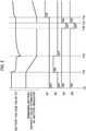
- FIG. 2 is an example of a timing chart in the case of charging the secondary battery BA after discharging the secondary battery BA in the power supply device 1 shown in FIG. 1 .
- the power supply device 1 shown in FIG. 1 discharges the secondary battery BA in a fully charged state in accordance with the timing chart shown in FIG. 2 , stops operation after discharging the secondary battery BA, and charges the secondary battery BA after being activated again.
- the timing chart shown in FIG. 2 In the timing chart shown in FIG.
- the axis of ordinates represents the battery voltage value of the secondary battery BA or the remaining battery capacity value estimated by the battery indicator 14 and the status of each switching element
- the axis of abscissas represents time. It is assumed that the power supply device 1 according to the present embodiment has been activated at the start of the timing chart shown in FIG. 2 (i.e., time T 0 ). That is, it is assumed that the switching elements Q3, Q4 have been turned on by the controller 11 at time T 0 .
- the power supply device 1 neither charges nor discharges the secondary battery BA in a period from above-mentioned time To until immediately before time T sd to start the discharge of the secondary battery BA. In this period, the battery voltage value of the secondary battery BA and the remaining battery capacity value estimated by the battery indicator 14 are constant.
- the controller 11 of the control unit CU turns off the switching elements Q1, Q2. As described above, the controller 11 maintains the switching elements Q3, Q4 in the on-state.
- the power supply device 1 starts discharging the secondary battery BA, discharges the secondary battery BA just in the period, and then ends the discharge of the secondary battery BA.
- the battery voltage value of the secondary battery BA rapidly drops when the secondary battery BA is discharged, and the battery voltage value slowly drops in the middle of the period, and rapidly drops again when the discharge of the secondary battery BA is ended.
- the remaining battery capacity value estimated by the battery indicator 14 linearly decreases.
- the controller 11 turns on the switching element Q2, maintains the switching element Q1 in the off-state, and maintains the switching elements Q3, Q4 in the on-state.
- the controller 11 maintains the switching element Q1 in the off-state and maintains the switching elements Q2, Q3, Q4 in the on-state in a period immediately after above-mentioned time T sd until immediately before time T ed .
- the controller 11 turns off the switching element Q2, maintains the switching element Q1 in the off-state, and maintains the switching elements Q3, Q4 in the on-state.
- the power supply device 1 does not discharge the secondary battery BA and maintains the power supply to the charge-discharge circuit FC in a period immediately after above-mentioned time T ed until time T off at which the controller 11 instructs the driving power source Vcc to stop the power supply (i.e., the time at which the power supply device 1 is stopped).
- the power supply device 1 stops the power supply to the charge-discharge circuit FC, and the controller 11 instructs the driving power source Vcc to stop the power supply.
- the battery voltage value of the secondary battery BA gradually increases, and at the end of the period, the battery voltage value becomes constant. Further, the remaining battery capacity value estimated by the battery indicator 14 is constant.
- the estimation method for the battery voltage by the battery indicator 14 is considered.
- the battery indicator 14 is configured to estimate the remaining battery capacity of the secondary battery BA from the battery voltage of the secondary battery BA. That is, the remaining battery capacity does not increase or decrease unless the secondary battery BA is charged or discharged. Hence the remaining battery capacity value estimated by the battery indicator 14 is constant.
- the controller 11 In the period immediately after above-mentioned time T ed until immediately before time T off , the controller 11 maintains the switching elements Q1, Q2 in the off-state and maintains the switching elements Q3, Q4 in the on-state. At above-mentioned time T off , the controller 11 maintains the switching elements Q1, Q2 in the off-state and turns off the switching elements Q3, Q4. That is, the controller 11 in the present embodiment instructs the driving power source Vcc to stop the power supply after the discharge of the secondary battery BA by the charge-discharge circuit FC is ended and at a timing when the battery voltage being measured by the voltage measurer 13 is stabilized. In the power supply device 1 according to the present embodiment, the timing at which the battery voltage of the secondary battery BA is stabilized is the timing at which the rate of change in the battery voltage per time falls below a predetermined threshold value.
- the power supply device 1 stops operation by the controller 11 instructing the driving power source Vcc to stop the power supply.
- the power supply device 1 starts the operation by the controller 11 instructing the driving power source Vcc to start power supply and starts the power supply from the control unit CU to the charge-discharge circuit FC.
- the battery voltage value of the secondary battery BA and the remaining battery capacity value estimated by the battery indicator 14 are constant.
- the controller 11 maintains the switching elements Q1, Q2, Q3, Q4 in the off-state in the period immediately after above-mentioned time T off until immediately before time T on .
- the controller 11 maintains the switching elements Q1, Q2 in the off-state and turns on the switching elements Q3, Q4 at above-mentioned time T on .
- the power supply device 1 supplies power from the control unit CU to the charge-discharge circuit FC in a period immediately after above-mentioned time T on until time T sc to charge the secondary battery BA and charges the secondary battery BA after supplying power from the control unit CU to the charge-discharge circuit FC.
- the battery voltage value of the secondary battery BA and the remaining battery capacity value estimated by the battery indicator 14 are constant.
- the controller 11 maintains the switching elements Q1, Q2 in the off-state and maintains the switching elements Q3, Q4 in the on-state.
- the controller 11 turns on the switching element Q1, maintains the switching element Q2 in the off-state, and maintains the switching elements Q3, Q4 in the on-state.
- the power supply device 1 continues to charge the secondary battery BA after above-mentioned time T sc .
- the battery voltage value of the secondary battery BA rapidly rises immediately after the secondary battery BA is charged and then gradually rises.
- the remaining battery capacity value estimated by the battery indicator 14 linearly increases.
- the controller 11 maintains the switching element Q1, Q3, Q4 in the on-state and maintains the switching element Q2 in the off-state after above-mentioned time T sc .
- the controller 11 of the control unit CU stops the power supply to the charge-discharge circuit FC after the discharge of the secondary battery BA by the charge-discharge circuit FC is ended and at a timing when a battery voltage being measured by a voltage measurer 13 is stabilized.
- the battery indicator 14 of the control unit CU estimates a remaining battery capacity when the controller 11 instructs the driving power source Vcc to start the power supply based on a battery voltage detected at a timing when the controller 11 instructs the driving power source Vcc to start the power supply.
- the driving power source Vcc is instructed to stop the power supply at a timing when the battery voltage of the secondary battery BA is not stable (i.e., the timing when the rate of change in the battery voltage per time is large.).
- the battery voltage continues to fluctuate even after the discharge of the secondary battery is ended, so that the estimated remaining battery capacity becomes low as indicated by a thin line in FIG. 3 , and an error occurs in the remaining battery capacity value, although the remaining battery capacity value should be estimated as indicated by a thick line in FIG. 3 .
- the controller 11 of the control unit CU instructs the driving power source Vcc to stop the power supply at a timing when the battery voltage measured by the voltage measurer 13 is stabilized in consideration of the fluctuation of the battery voltage.
- the power supply device 1 according to the present embodiment estimates the remaining battery capacity in consideration of the above error and can thus accurately estimate the remaining battery capacity of the secondary battery BA. That is, the power supply device 1 according to the present embodiment can improve the estimation accuracy of the remaining battery capacity.
- control unit CU in the present embodiment is incorporated in the battery pack BP.
- control unit CU in the present embodiment is not limited thereto.
- the control unit CU in the present embodiment may be incorporated as a component of the power supply device 1.
- the timing at which the battery voltage of the secondary battery BA is stabilized is a timing at which the rate of change in the battery voltage per time falls below a predetermined threshold value.
- the power supply device 1 according to the present embodiment is not limited thereto.
- the timing at which the battery voltage is stabilized may be a timing at which a preset time has elapsed after the discharge is ended. In this case, the set time is from 30 minutes to two hours.
- the timing at which the battery voltage is stabilized may be a timing at which the battery voltage changes by a predetermined value with respect to the battery voltage when the discharge is ended.
- the power that can be supplied to the load 2 and the power that can be supplied to the secondary battery BA are the same, as can be seen from the fact that the paths are shared.
- the power supply device 1 according to the present embodiment is not limited thereto.
- an inverter may be further provided in the power supply device 1 so that power converted to a desired voltage and stored into the secondary battery BA can be output.
- the external power source PS in the present embodiment may be a household power source or a commercial power source.
- the external power source PS may be a power source capable of supplying DC power or a power source capable of supplying AC power. That is, the power supply device 1 according to the present embodiment can appropriately change the internal configuration in accordance with the type of the external power source PS and the power available in the load 2.
- the voltage converter CV in the present embodiment can be changed appropriately in accordance with the type of the external power source PS and the power available in the load 2.
- the voltage converter CV in the present embodiment may be a rectifier (AC-to-DC converter) or a DC-to-DC converter.
- the secondary battery BA in the present embodiment is a battery generally known, for example, a lithium-ion battery or a lead storage battery.
- the load 2 in the present embodiment is assumed to be, for example, a personal computer, a server, a storage device, or other devices that are required to operate for a certain period of time when the power supply from the external power source PS is stopped.
- predetermined processor means, for example, a dedicated or general-purpose processor such as a central processing unit (CPU), a micro processing unit (MPU), or a graphics processing unit (GPU), an application-specific integrated circuit (ASIC), a programmable logic device (e.g., a simple programmable logic device (SPLD), a complex programmable logic device (CPLD), a field-programmable gate array (FPGA)), or the like.
- CPU central processing unit
- MPU micro processing unit
- GPU graphics processing unit
- ASIC application-specific integrated circuit
- SPLD simple programmable logic device
- CPLD complex programmable logic device
- FPGA field-programmable gate array
Landscapes
- Engineering & Computer Science (AREA)
- Power Engineering (AREA)
- Business, Economics & Management (AREA)
- Emergency Management (AREA)
- Charge And Discharge Circuits For Batteries Or The Like (AREA)
- Secondary Cells (AREA)
Abstract
A battery indicator (14) estimates a remaining battery capacity when a controller (11) instructs a driving power source (Vcc) to start the power supply based on a battery voltage detected at a timing when the controller (11) instructs the driving power source (Vcc) to start the power supply. The controller (11) instructs the driving power source (Vcc) to stop the power supply after the discharge of a secondary battery (BA) by a charge-discharge circuit (FC) is ended and at a timing when a battery voltage being measured by a voltage measurer (13) is stabilized.
Description
- The present invention relates to a control unit for controlling the operation of a charge-discharge circuit that charges or discharges a secondary battery and to a battery pack and a power supply device including the control unit.
- In general, an electronic device such as a battery pack or a power supply device includes a secondary battery and a battery indicator capable of estimating the remaining battery capacity of the secondary battery. The battery indicator detects a charging current flowing to the secondary battery in the case of charging secondary battery and a discharging current output from the secondary battery in the case of discharging the secondary battery and estimates the remaining battery capacity of the secondary battery based on the charging current and the discharging current.
- The battery voltage of the secondary battery is higher during charge and lower during discharge than an open-circuit voltage (OCV), which indicates a battery voltage when charge or discharge is not performed. Further, the battery voltage of the secondary battery has a characteristic of gradually approaching the OCV when the charge and discharge are ended. Here, the remaining battery capacity at the time of power supply to a microcomputer held in the electronic device is estimated based on the battery voltage. The remaining battery capacity is estimated assuming that the battery voltage at this time is the OCV. That is, a problem is that, when the power supply to the microcomputer is cut off and applied again without a time interval after the charge or discharge of the secondary battery, the estimation accuracy of the remaining battery capacity deteriorates.
- The object of the present invention is to provide a control unit, a battery pack, and a power supply device capable of improving the estimation accuracy of the remaining battery capacity of a secondary battery at a point in time when an electronic device starts from a stop (shutdown).
- For achieving the above object, a control unit according to the present aspect is a control unit for controlling the operation of a charge-discharge circuit that charges or discharges a secondary battery, the control unit including: a controller configured to control power supply for causing the charge-discharge circuit to operate; a driving power source that supplies drive power to the controller; a voltage measurer configured to measure a battery voltage of the secondary battery; and a battery indicator configured to estimate a remaining battery capacity of the secondary battery from a battery voltage of the secondary battery measured by the voltage measurer.
- The battery indicator estimates the remaining battery capacity when the controller instructs the driving power source to start power supply based on the battery voltage detected at a timing when the controller instructs the driving power source to start the power supply. The controller instructs the driving power source to stop the power supply after the discharge of the secondary battery by the charge-discharge circuit is ended and at a timing when the battery voltage measured by the voltage measurer is stabilized. With the configuration described above, the control unit according to the present aspect can improve the estimation accuracy of the remaining battery capacity of the secondary battery at the point in time of starting from the stop (shutdown).
- In the control unit according to the present aspect, the timing at which the battery voltage is stabilized is preferably a timing at which the rate of change in the battery voltage per time falls below a predetermined threshold value. With the configuration described above, the control unit according to the present aspect can improve the estimation accuracy of the remaining battery capacity of the secondary battery at the point in time of starting from the stop (shutdown).
- In the control unit according to the present aspect, the timing at which the battery voltage is stabilized is preferably a timing at which a preset time has elapsed after the discharge is ended. With the configuration described above, the control unit according to the present aspect can improve the estimation accuracy of the remaining battery capacity of the secondary battery at the point in time of starting from the stop (shutdown).
- In the control unit according to the present aspect, the time is preferably from 30 minutes to two hours. With the configuration described above, the control unit according to the present aspect can improve the estimation accuracy of the remaining battery capacity of the secondary battery at the point in time of starting from the stop (shutdown).
- In the control unit according to the present aspect, the timing at which the battery voltage is stabilized is preferably a timing at which the battery voltage changes by a predetermined value with respect to the battery voltage when the discharge is ended. With the configuration described above, the control unit according to the present aspect can improve the estimation accuracy of the remaining battery capacity of the secondary battery at the point in time of starting from the stop (shutdown).
- A battery pack according to the present aspect includes the control unit according to the present aspect, the charge-discharge circuit, and the secondary battery. With the configuration described above, the battery pack according to the present aspect can improve the estimation accuracy of the remaining battery capacity of the secondary battery at the point in time of starting from the stop (shutdown).
- A power supply device according to the present aspect includes the control unit according to the present embodiment, the charge-discharge circuit, and the secondary battery. With the configuration described above, the power supply device according to the present aspect can improve the estimation accuracy of the remaining battery capacity of the secondary battery at the point in time of starting from the stop (shutdown).
-
-
FIG. 1 is a circuit diagram showing a power supply device according to the present embodiment; -
FIG. 2 is an example of a timing chart in the case of charging the secondary battery after discharging the secondary battery in the power supply device shown inFIG. 1 ; -
FIG. 3 is a diagram for explaining the effect of the power supply device according to the present embodiment; and -
FIG. 4 is a circuit diagram showing a power supply device according to a modified example. - Hereinafter, a control unit, a battery pack, and a power supply device according to an embodiment will be described with reference to the drawings. Note that the present embodiment is not limited to the content described below but can be implemented with an arbitrary change in the scope where the gist thereof is not changed. The drawings for use in the description of the embodiments schematically show constituent members, are partially emphasized, enlarged, reduced, or omitted for better understanding, and may not accurately show the scale, shape, or the like of the constituent members.
-
FIG. 1 is a circuit diagram showing apower supply device 1 according to the present embodiment. Thepower supply device 1 shown inFIG. 1 converts power supplied from an external power source PS into power that can be supplied to aload 2 and supplies the power to theload 2. While supplying the power to theload 2, thepower supply device 1 charges a secondary battery BA incorporated in thepower supply device 1 itself by the power. When the power supply from the external power source PS is stopped due to a power failure or the like, thepower supply device 1 discharges the power stored in the secondary battery BA and supplies the power to theload 2. Note that thepower supply device 1 according to the present embodiment can charge the secondary battery BA while supplying the power to theload 2. - As shown in
FIG. 1 , thepower supply device 1 according to the present embodiment includes a voltage converter CV and a battery pack BP. The battery pack BP includes a charge-discharge circuit FC and a control unit CU together with the secondary battery BA. The voltage converter CV converts power supplied from the external power source PS into power that can be supplied to theload 2 and supplies the power to theload 2. Also, the voltage converter CV converts the power supplied from the external power source PS into power that can be supplied to the secondary battery BA via the charge-discharge circuit FC and supplies the power to the secondary battery BA. - The charge-discharge circuit FC charges and discharges the secondary battery BA under the control of the control unit CU. The charge-discharge circuit FC in the present embodiment is provided with switching elements Q1, Q2. The switching element Q1 is provided in an electrical path L1 between the voltage converter CV and the secondary battery BA. More specifically, the gate of the switching element Q1 is connected to the controller 11 of the control unit CU to be described later. The drain of the switching element Q1 is connected to the voltage converter CV. The source of the switching element Q1 is connected to the secondary battery BA.
- One end of the switching element Q2 is connected to an electrical path L2 between the switching element Q1 and the secondary battery BA, and the other end of the switching element Q2 is connected to an electrical path L3 between the voltage converter CV and the
load 2. More specifically, the gate of the switching element Q2 is connected to the controller 11 of the control unit CU to be described later. The drain (the one end) of the switching element Q2 is connected to the electrical path L2. The source (the other end) of the switching element Q2 is connected to the electrical path L3. - The charge-discharge circuit FC in the present embodiment performs the on/off operation of the switching element Q1 or the switching element Q2 under the control of the control unit CU to charge or discharge the secondary battery BA. For example, when charging the secondary battery BA, the charge-discharge circuit FC turns on the switching element Q1 and turns off the switching element Q2. Thus, the power is supplied from the external power source PS to the secondary battery BA via the voltage converter CV and the switching element Q1, and the power is stored into the secondary battery BA. When discharging the secondary battery BA, the charge-discharge circuit FC turns on the switching element Q2 and turns off the switching element Q1. Thus, the power is supplied from the secondary battery BA to the
load 2 via the switching element Q2. - The control unit CU controls the operation of the charge-discharge circuit FC. The control unit CU in the present embodiment includes a controller 11, a switching element Q3, a switching element Q4, a
regulator 12, avoltage measurer 13, and abattery indicator 14. - The controller 11 includes a predetermined processor as a hardware resource. The controller 11 is connected to a driving power source Vcc that supplies power for driving the controller 11 to the controller 11. The controller 11 is configured to control power supply for causing the charge-discharge circuit FC to operate. As shown in
FIG. 1 , the controller 11 in the present embodiment is connected to the gates of the switching elements Q1, Q2 in the charge-discharge circuit FC and the gate of the switching element Q4 in the control unit CU. The controller 11 applies a predetermined gate voltage to the gate of each of the switching elements Q1, Q2, Q4 to turn on each of the switching elements Q1, Q2, Q4. - The controller 11 is configured to turn on the switching elements Q3, Q4 at a timing of instructing the driving power source Vcc to start power supply (i.e., the timing of activating the power supply device 1) and to turn off the switching elements Q3, Q4 at a timing of instructing the driving power source Vcc to stop the power supply (i.e., the timing of stopping (shutting down) the power supply device 1). By detecting a voltage Vreg output from the
regulator 12, the controller 11 can recognize that the charging operation is being executed. Here, theregulator 12 is connected in parallel to the switching element Q1 via the switching element Q3 and is configured to keep constant the power supplied from the voltage converter CV to the secondary battery BA. - Here, the gate of the switching element Q3 is connected to the drain of the switching element Q4. The drain of the switching element Q3 is connected to an electrical path L4 between the source of the switching element Q1 and the connection point of the electrical path L2 to which the drain of the switching element Q2 is connected. The source of the switching element Q3 is connected to the
regulator 12. The gate of the switching element Q4 is connected to the controller 11 as described above. The drain of the switching element Q4 is connected to the gate of the switching element Q3 as described above. The source of the switching element Q4 is grounded. That is, by the controller 11 applying a predetermined gate voltage to the gate of the switching element Q4, the switching element Q4 is turned on. Further, by turning on the switching element Q4, a gate voltage is applied to the gate of the switching element Q3. Thereby, the switching element Q3 is turned on. - The
voltage measurer 13 is connected in parallel to the secondary battery BA and is configured to measure the battery voltage of the secondary battery BA. Thebattery indicator 14 is configured to estimate the remaining battery capacity of the secondary battery BA from the battery voltage of the secondary battery BA measured by thevoltage measurer 13. For example, thebattery indicator 14 in the present embodiment estimates a remaining battery capacity when the controller 11 instructs the driving power source Vcc to start power supply based on the battery voltage detected at a timing when the controller 11 instructs the driving power source Vcc to start the power supply. Further, thebattery indicator 14 is configured to display the remaining battery capacity. For example, thebattery indicator 14 displays the remaining battery capacity on a display device (not shown) such as a display incorporated in thebattery indicator 14 itself or an external display. - Here, in the
power supply device 1 according to the present embodiment, a diode D is provided in each of: an electrical path L5 between the source of the switching element Q1 and the connection point of the electrical path L4 to which the drain of the switching element Q3 is connected; an electrical path L6 between the source of the switching element Q2 and the connection point of the electrical path L3 to which the source of the switching element Q2 is connected; an electrical path L7 between the voltage converter CV and the connection point of the electrical path L3 to which the source of the switching element Q2 is connected; and an electrical path L8 between the switching element Q1 and the switching element Q3, thereby preventing the reverse flow of the current in each path. - Next, the relationship between the battery voltage of the secondary battery BA and the on/off-state of each switching element will be described in detail with reference to
FIG. 2. FIG. 2 is an example of a timing chart in the case of charging the secondary battery BA after discharging the secondary battery BA in thepower supply device 1 shown inFIG. 1 . Note that thepower supply device 1 shown inFIG. 1 discharges the secondary battery BA in a fully charged state in accordance with the timing chart shown inFIG. 2 , stops operation after discharging the secondary battery BA, and charges the secondary battery BA after being activated again. In the timing chart shown inFIG. 2 , the axis of ordinates represents the battery voltage value of the secondary battery BA or the remaining battery capacity value estimated by thebattery indicator 14 and the status of each switching element, and the axis of abscissas represents time. It is assumed that thepower supply device 1 according to the present embodiment has been activated at the start of the timing chart shown inFIG. 2 (i.e., time T0). That is, it is assumed that the switching elements Q3, Q4 have been turned on by the controller 11 at time T0. - First, as shown in
FIG. 2 , thepower supply device 1 according to the present embodiment neither charges nor discharges the secondary battery BA in a period from above-mentioned time To until immediately before time Tsd to start the discharge of the secondary battery BA. In this period, the battery voltage value of the secondary battery BA and the remaining battery capacity value estimated by thebattery indicator 14 are constant. - The controller 11 of the control unit CU turns off the switching elements Q1, Q2. As described above, the controller 11 maintains the switching elements Q3, Q4 in the on-state.
- Next, as shown in
FIG. 2 , in a period from above-mentioned time Tsd to time Ted when the discharge of the secondary battery BA is ended, thepower supply device 1 according to the present embodiment starts discharging the secondary battery BA, discharges the secondary battery BA just in the period, and then ends the discharge of the secondary battery BA. In this period, due to the discharge characteristics of the secondary battery BA, the battery voltage value of the secondary battery BA rapidly drops when the secondary battery BA is discharged, and the battery voltage value slowly drops in the middle of the period, and rapidly drops again when the discharge of the secondary battery BA is ended. The remaining battery capacity value estimated by thebattery indicator 14 linearly decreases. - At above-mentioned time Tsd, the controller 11 turns on the switching element Q2, maintains the switching element Q1 in the off-state, and maintains the switching elements Q3, Q4 in the on-state. The controller 11 maintains the switching element Q1 in the off-state and maintains the switching elements Q2, Q3, Q4 in the on-state in a period immediately after above-mentioned time Tsd until immediately before time Ted. At above-mentioned time Ted, the controller 11 turns off the switching element Q2, maintains the switching element Q1 in the off-state, and maintains the switching elements Q3, Q4 in the on-state.
- Next, as shown in
FIG. 2 , thepower supply device 1 according to the present embodiment does not discharge the secondary battery BA and maintains the power supply to the charge-discharge circuit FC in a period immediately after above-mentioned time Ted until time Toff at which the controller 11 instructs the driving power source Vcc to stop the power supply (i.e., the time at which thepower supply device 1 is stopped). After maintaining the power supply to the charge-discharge circuit FC, thepower supply device 1 stops the power supply to the charge-discharge circuit FC, and the controller 11 instructs the driving power source Vcc to stop the power supply. In this period, the battery voltage value of the secondary battery BA gradually increases, and at the end of the period, the battery voltage value becomes constant. Further, the remaining battery capacity value estimated by thebattery indicator 14 is constant. - Here, as a reason why the remaining battery capacity value estimated by the
battery indicator 14 is constant, the estimation method for the battery voltage by thebattery indicator 14 is considered. Thebattery indicator 14 is configured to estimate the remaining battery capacity of the secondary battery BA from the battery voltage of the secondary battery BA. That is, the remaining battery capacity does not increase or decrease unless the secondary battery BA is charged or discharged. Hence the remaining battery capacity value estimated by thebattery indicator 14 is constant. - In the period immediately after above-mentioned time Ted until immediately before time Toff, the controller 11 maintains the switching elements Q1, Q2 in the off-state and maintains the switching elements Q3, Q4 in the on-state. At above-mentioned time Toff, the controller 11 maintains the switching elements Q1, Q2 in the off-state and turns off the switching elements Q3, Q4. That is, the controller 11 in the present embodiment instructs the driving power source Vcc to stop the power supply after the discharge of the secondary battery BA by the charge-discharge circuit FC is ended and at a timing when the battery voltage being measured by the
voltage measurer 13 is stabilized. In thepower supply device 1 according to the present embodiment, the timing at which the battery voltage of the secondary battery BA is stabilized is the timing at which the rate of change in the battery voltage per time falls below a predetermined threshold value. - Next, as shown in
FIG. 2 , for example, in a period immediately after above-mentioned time Toff until time Ton at which the controller 11 instructs the driving power source Vcc to start power supply, (i.e., the time at which thepower supply device 1 is activated), thepower supply device 1 according to the present embodiment stops operation by the controller 11 instructing the driving power source Vcc to stop the power supply. After stopping the operation, thepower supply device 1 starts the operation by the controller 11 instructing the driving power source Vcc to start power supply and starts the power supply from the control unit CU to the charge-discharge circuit FC. In this period, the battery voltage value of the secondary battery BA and the remaining battery capacity value estimated by thebattery indicator 14 are constant. - The controller 11 maintains the switching elements Q1, Q2, Q3, Q4 in the off-state in the period immediately after above-mentioned time Toff until immediately before time Ton. The controller 11 maintains the switching elements Q1, Q2 in the off-state and turns on the switching elements Q3, Q4 at above-mentioned time Ton.
- Next, as shown in
FIG. 2 , for example, thepower supply device 1 according to the present embodiment supplies power from the control unit CU to the charge-discharge circuit FC in a period immediately after above-mentioned time Ton until time Tsc to charge the secondary battery BA and charges the secondary battery BA after supplying power from the control unit CU to the charge-discharge circuit FC. In this period, the battery voltage value of the secondary battery BA and the remaining battery capacity value estimated by thebattery indicator 14 are constant. - In the period immediately after above-mentioned time Ton until immediately before time Tsc, the controller 11 maintains the switching elements Q1, Q2 in the off-state and maintains the switching elements Q3, Q4 in the on-state. At above-mentioned time Tsc, the controller 11 turns on the switching element Q1, maintains the switching element Q2 in the off-state, and maintains the switching elements Q3, Q4 in the on-state.
- Finally, as shown in
FIG. 2 , thepower supply device 1 according to the present embodiment continues to charge the secondary battery BA after above-mentioned time Tsc. In this period, the battery voltage value of the secondary battery BA rapidly rises immediately after the secondary battery BA is charged and then gradually rises. The remaining battery capacity value estimated by thebattery indicator 14 linearly increases. - The controller 11 maintains the switching element Q1, Q3, Q4 in the on-state and maintains the switching element Q2 in the off-state after above-mentioned time Tsc.
- As described above, in the
power supply device 1 according to the present embodiment, the controller 11 of the control unit CU stops the power supply to the charge-discharge circuit FC after the discharge of the secondary battery BA by the charge-discharge circuit FC is ended and at a timing when a battery voltage being measured by avoltage measurer 13 is stabilized. Thebattery indicator 14 of the control unit CU estimates a remaining battery capacity when the controller 11 instructs the driving power source Vcc to start the power supply based on a battery voltage detected at a timing when the controller 11 instructs the driving power source Vcc to start the power supply. - For example, as shown in
FIG. 3 , consider that, immediately after the discharge of the secondary battery BA is stopped, the driving power source Vcc is instructed to stop the power supply at a timing when the battery voltage of the secondary battery BA is not stable (i.e., the timing when the rate of change in the battery voltage per time is large.). In this case, due to the influence of the fluctuation of the battery voltage, the battery voltage continues to fluctuate even after the discharge of the secondary battery is ended, so that the estimated remaining battery capacity becomes low as indicated by a thin line inFIG. 3 , and an error occurs in the remaining battery capacity value, although the remaining battery capacity value should be estimated as indicated by a thick line inFIG. 3 . - On the other hand, in the
power supply device 1 according to the present embodiment, the controller 11 of the control unit CU instructs the driving power source Vcc to stop the power supply at a timing when the battery voltage measured by thevoltage measurer 13 is stabilized in consideration of the fluctuation of the battery voltage. As a result, thepower supply device 1 according to the present embodiment estimates the remaining battery capacity in consideration of the above error and can thus accurately estimate the remaining battery capacity of the secondary battery BA. That is, thepower supply device 1 according to the present embodiment can improve the estimation accuracy of the remaining battery capacity. - As shown in
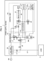
FIG. 1 , the control unit CU in the present embodiment is incorporated in the battery pack BP. However, the control unit CU in the present embodiment is not limited thereto. For example, as shown inFIG. 4 , the control unit CU in the present embodiment may be incorporated as a component of thepower supply device 1. - In the
power supply device 1 according to the present embodiment, the timing at which the battery voltage of the secondary battery BA is stabilized is a timing at which the rate of change in the battery voltage per time falls below a predetermined threshold value. However, thepower supply device 1 according to the present embodiment is not limited thereto. For example, in thepower supply device 1 according to the present embodiment, the timing at which the battery voltage is stabilized may be a timing at which a preset time has elapsed after the discharge is ended. In this case, the set time is from 30 minutes to two hours. Alternatively, the timing at which the battery voltage is stabilized may be a timing at which the battery voltage changes by a predetermined value with respect to the battery voltage when the discharge is ended. - In the present embodiment, the power that can be supplied to the
load 2 and the power that can be supplied to the secondary battery BA are the same, as can be seen from the fact that the paths are shared. However, thepower supply device 1 according to the present embodiment is not limited thereto. In the present embodiment, an inverter may be further provided in thepower supply device 1 so that power converted to a desired voltage and stored into the secondary battery BA can be output. - The external power source PS in the present embodiment may be a household power source or a commercial power source. The external power source PS may be a power source capable of supplying DC power or a power source capable of supplying AC power. That is, the
power supply device 1 according to the present embodiment can appropriately change the internal configuration in accordance with the type of the external power source PS and the power available in theload 2. At this time, the voltage converter CV in the present embodiment can be changed appropriately in accordance with the type of the external power source PS and the power available in theload 2. For example, the voltage converter CV in the present embodiment may be a rectifier (AC-to-DC converter) or a DC-to-DC converter. - Note that the secondary battery BA in the present embodiment is a battery generally known, for example, a lithium-ion battery or a lead storage battery. The
load 2 in the present embodiment is assumed to be, for example, a personal computer, a server, a storage device, or other devices that are required to operate for a certain period of time when the power supply from the external power source PS is stopped. - The term "predetermined processor" used in the above description means, for example, a dedicated or general-purpose processor such as a central processing unit (CPU), a micro processing unit (MPU), or a graphics processing unit (GPU), an application-specific integrated circuit (ASIC), a programmable logic device (e.g., a simple programmable logic device (SPLD), a complex programmable logic device (CPLD), a field-programmable gate array (FPGA)), or the like. Each component of the present embodiment is not limited to a single processor but may be achieved by a plurality of processors. A plurality of components may be achieved by a single processor.
Claims (7)
- A control unit (CU) for controlling operation of a charge-discharge circuit (FC) that charges or discharges a secondary battery (BA) characterized in that the control unit comprises:a controller (11) configured to control power supply for causing the charge-discharge circuit (FC) to operate;a driving power source (Vcc) that supplies drive power to the controller (11);a voltage measurer (13) configured to measure a battery voltage of the secondary battery (BA); anda battery indicator (14) configured to estimate a remaining battery capacity of the secondary battery (BA) from a battery voltage of the secondary battery (BA) measured by the voltage measurer (13),the battery indicator (14) estimates the remaining battery capacity when the controller (11) instructs the driving power source (Vcc) to start power supply based on the battery voltage detected at a timing when the controller (11) instructs the driving power source (Vcc) to start the power supply, andthe controller (11) instructs the driving power source (Vcc) to stop the power supply after the discharge of the secondary battery (BA) by the charge-discharge circuit (FC) is ended and at a timing when the battery voltage measured by the voltage measurer (13) is stabilized.
- The control unit (CU) according to claim 1, characterized in that the timing at which the battery voltage is stabilized is a timing at which a rate of change in the battery voltage per time falls below a predetermined threshold value.
- The control unit (CU) according to any one of the previous claims, characterized in that the timing at which the battery voltage is stabilized is a timing at which a preset time elapses after the discharge is ended.
- The control unit (CU) according to any one of the previous claims, characterized in that the time is from 30 minutes to two hours.
- The control unit (CU) according to any one of the previous claims, characterized in that the timing at which the battery voltage is stabilized is a timing at which the battery voltage changes by a predetermined value with respect to the battery voltage when the discharge is ended.
- A battery pack (BP) comprising:a control unit (CU) that controls operation of a charge-discharge circuit (FC) that charges or discharges a secondary battery (BA);the charge-discharge circuit (FC); andthe secondary battery (BA),characterized in thatthe control unit (CU) includesa controller (11) configured to control power supply for causing the charge-discharge circuit (FC) to operate,a driving power source (Vcc) that supplies drive power to the controller (11),a voltage measurer (13) configured to measure a battery voltage of the secondary battery (BA), anda battery indicator (14) configured to estimate a remaining battery capacity of the secondary battery (BA) from a battery voltage of the secondary battery (BA) measured by the voltage measurer (13),the battery indicator (14) estimates the remaining battery capacity when the controller (11) instructs the driving power source (Vcc) to start power supply based on the battery voltage detected at a timing when the controller (11) instructs the driving power source (Vcc) to start the power supply, andthe controller (11) instructs the driving power source (Vcc) to stop the power supply after the discharge of the secondary battery (BA) by the charge-discharge circuit (FC) is ended and at a timing when the battery voltage measured by the voltage measurer (13) is stabilized.
- A power supply device (1) comprising:a control unit (CU) that controls operation of a charge-discharge circuit (FC) that charges or discharges a secondary battery (BA);the charge-discharge circuit (FC); andthe secondary battery (BA),characterized in thatthe control unit (CU) includesa controller (11) configured to control power supply for causing the charge-discharge circuit (FC) to operate,a driving power source (Vcc) that supplies drive power to the controller (11),a voltage measurer (13) configured to measure a battery voltage of the secondary battery (BA), anda battery indicator (14) configured to estimate a remaining battery capacity of the secondary battery (BA) from a battery voltage of the secondary battery (BA) measured by the voltage measurer (13),the battery indicator (14) estimates the remaining battery capacity when the controller (11) instructs the driving power source (Vcc) to start power supply based on the battery voltage detected at a timing when the controller (11) instructs the driving power source (Vcc) to start the power supply, andthe controller (11) instructs the driving power source (Vcc) to stop the power supply after the discharge of the secondary battery (BA) by the charge-discharge circuit (FC) is ended and at a timing when the battery voltage measured by the voltage measurer (13) is stabilized.
Applications Claiming Priority (1)
| Application Number | Priority Date | Filing Date | Title |
|---|---|---|---|
| JP2020123934A JP7544521B2 (en) | 2020-07-20 | 2020-07-20 | Control device, battery pack and power supply device |
Publications (1)
| Publication Number | Publication Date |
|---|---|
| EP3944460A1 true EP3944460A1 (en) | 2022-01-26 |
Family
ID=77179866
Family Applications (1)
| Application Number | Title | Priority Date | Filing Date |
|---|---|---|---|
| EP21185192.8A Pending EP3944460A1 (en) | 2020-07-20 | 2021-07-13 | Control unit, battery pack, and power supply device |
Country Status (4)
| Country | Link |
|---|---|
| US (1) | US12119698B2 (en) |
| EP (1) | EP3944460A1 (en) |
| JP (1) | JP7544521B2 (en) |
| CN (1) | CN113964891B (en) |
Families Citing this family (2)
| Publication number | Priority date | Publication date | Assignee | Title |
|---|---|---|---|---|
| WO2023153043A1 (en) | 2022-02-14 | 2023-08-17 | 株式会社Ihi | Rotating electric machine |
| WO2025131717A2 (en) * | 2023-12-18 | 2025-06-26 | Robert Bosch Gmbh | Power supply system for battery operated tools |
Citations (1)
| Publication number | Priority date | Publication date | Assignee | Title |
|---|---|---|---|---|
| US5525888A (en) * | 1993-05-14 | 1996-06-11 | Sanyo Electric Co., Ltd. | Battery charger, battery case, and electronic equipment |
Family Cites Families (27)
| Publication number | Priority date | Publication date | Assignee | Title |
|---|---|---|---|---|
| US5939855A (en) * | 1994-09-06 | 1999-08-17 | Cruising Equipment, Inc. | Power conversion equipment monitor/controller method and apparatus |
| JP2001238358A (en) | 2000-02-24 | 2001-08-31 | Toshiba Battery Co Ltd | Secondary cell device |
| JP2002218668A (en) * | 2001-01-19 | 2002-08-02 | Fujitsu Ltd | Portable information processing device, charging device and method |
| JP4423800B2 (en) | 2001-03-26 | 2010-03-03 | トヨタ自動車株式会社 | Battery capacity determination method and determination device, power transfer control method and control device |
| JP4239435B2 (en) | 2001-06-04 | 2009-03-18 | トヨタ自動車株式会社 | Battery capacity determination method and battery capacity determination device |
| JP3701664B2 (en) * | 2004-08-11 | 2005-10-05 | 九州日立マクセル株式会社 | Electric razor |
| JP4466656B2 (en) * | 2005-01-06 | 2010-05-26 | 日本電気株式会社 | Charge control device and charge control method for mobile phone terminal |
| TWI274454B (en) * | 2005-03-04 | 2007-02-21 | Ind Tech Res Inst | A power management method and system of a hybrid power supply |
| JP2010104129A (en) * | 2008-10-22 | 2010-05-06 | Sanyo Electric Co Ltd | Power supply system, power supply side controller, and electric motor car |
| JP2011169831A (en) | 2010-02-19 | 2011-09-01 | Mitsumi Electric Co Ltd | Device and method for detection of battery state |
| JP5971580B2 (en) * | 2011-11-22 | 2016-08-17 | パナソニックIpマネジメント株式会社 | Discharge system |
| US20130158914A1 (en) | 2011-12-16 | 2013-06-20 | Chung-Shan Institute of Science and Technology, Armaments, Bureau, Ministry of National Defense | Apparatus for Measuring the State of Charge of a Battery Pack via Measuring an Open Circuit Voltage |
| JP2014128142A (en) | 2012-12-27 | 2014-07-07 | Fdk Corp | Uninterruptible power supply unit |
| KR101916969B1 (en) * | 2013-01-22 | 2018-11-08 | 삼성에스디아이 주식회사 | Charging method of battery and battery pack thereof |
| JP2014220236A (en) | 2013-04-11 | 2014-11-20 | 株式会社東芝 | Secondary battery device |
| JP6187815B2 (en) * | 2013-09-25 | 2017-08-30 | パナソニックIpマネジメント株式会社 | Electric tool |
| KR102165937B1 (en) * | 2014-05-30 | 2020-10-14 | 삼성전자주식회사 | Method and apparatus for managing battery |
| JP6242008B2 (en) * | 2014-06-25 | 2017-12-06 | Fdk株式会社 | Uninterruptible power system |
| JP6296608B2 (en) * | 2014-06-26 | 2018-03-20 | Fdk株式会社 | Uninterruptible power system |
| CN105375072B (en) | 2014-08-15 | 2017-09-01 | 艾默生网络能源有限公司 | A kind of method for charging batteries and device |
| KR20160063756A (en) | 2014-11-27 | 2016-06-07 | 삼성에스디아이 주식회사 | Battery pack and method for controlling the same |
| CN109075606B (en) | 2016-05-12 | 2021-11-30 | 三菱电机株式会社 | Standby power supply device during power failure |
| JP6916639B2 (en) * | 2017-03-13 | 2021-08-11 | エイブリック株式会社 | Charge / discharge control circuit and battery device |
| JP6903456B2 (en) * | 2017-03-15 | 2021-07-14 | エイブリック株式会社 | Charge / discharge control circuit and battery device |
| JP6801613B2 (en) * | 2017-09-06 | 2020-12-16 | 株式会社豊田自動織機 | Battery pack |
| KR102731551B1 (en) * | 2019-03-04 | 2024-11-18 | 현대자동차주식회사 | System and method for controlling battery charging or discharging |
| JP7191873B2 (en) * | 2020-01-17 | 2022-12-19 | 株式会社東芝 | Charge/discharge control device, charge/discharge system, charge/discharge control method, and charge/discharge control program |
-
2020
- 2020-07-20 JP JP2020123934A patent/JP7544521B2/en active Active
-
2021
- 2021-07-07 US US17/305,401 patent/US12119698B2/en active Active
- 2021-07-13 EP EP21185192.8A patent/EP3944460A1/en active Pending
- 2021-07-20 CN CN202110819251.2A patent/CN113964891B/en active Active
Patent Citations (1)
| Publication number | Priority date | Publication date | Assignee | Title |
|---|---|---|---|---|
| US5525888A (en) * | 1993-05-14 | 1996-06-11 | Sanyo Electric Co., Ltd. | Battery charger, battery case, and electronic equipment |
Also Published As
| Publication number | Publication date |
|---|---|
| JP2022020442A (en) | 2022-02-01 |
| CN113964891A (en) | 2022-01-21 |
| US20220021231A1 (en) | 2022-01-20 |
| US12119698B2 (en) | 2024-10-15 |
| JP7544521B2 (en) | 2024-09-03 |
| CN113964891B (en) | 2025-02-25 |
Similar Documents
| Publication | Publication Date | Title |
|---|---|---|
| US8508190B2 (en) | Assembled battery system and assembled battery protection device | |
| CN101460859B (en) | Method for judging abnormality of battery pack and battery pack | |
| US9490661B2 (en) | Uninterruptible power supply | |
| US6445164B2 (en) | Power supply apparatus with chargeable battery and charge/discharge method | |
| US8558515B2 (en) | Protection circuit and electronic device | |
| JP6068366B2 (en) | Storage system and control method of secondary battery pack | |
| US10505477B2 (en) | Load drive current control method and system | |
| CN101099280B (en) | Charging control device and charging control method for portable phone terminal | |
| CN105009399A (en) | System and method for monitoring a battery in an uninterruptible power supply | |
| US12119698B2 (en) | Control unit, battery pack, and power supply device | |
| CN104813560A (en) | Battery | |
| US9231417B2 (en) | Rechargeable electrical device | |
| US10608455B2 (en) | Quick battery charging with protection based on regulation relative state of charge | |
| US20200132780A1 (en) | Power supply device | |
| TWI710781B (en) | System and method for low current sensing | |
| CN109962511B (en) | Semiconductor device | |
| CN110828913A (en) | Battery charging method and charging system thereof | |
| US6020720A (en) | Fast charging method and apparatus for secondary cells | |
| CN103384072B (en) | The electronic equipment of circuit is controlled with charging and discharging | |
| US20170210596A1 (en) | Charge algorithm for battery propelled elevator | |
| KR20190093405A (en) | Battery control unit compatible for lithium ion battery, and control method thereof | |
| JP2003348765A (en) | Charger and charge control circuit | |
| EP3823124A1 (en) | Power control circuit using a using lithium-ion capacitor as backup power source | |
| US20260106487A1 (en) | Uninterruptible power supply device | |
| US10164446B2 (en) | Discharge circuit malfunction diagnosis device and discharge circuit malfunction diagnosis method |
Legal Events
| Date | Code | Title | Description |
|---|---|---|---|
| PUAI | Public reference made under article 153(3) epc to a published international application that has entered the european phase |
Free format text: ORIGINAL CODE: 0009012 |
|
| STAA | Information on the status of an ep patent application or granted ep patent |
Free format text: STATUS: REQUEST FOR EXAMINATION WAS MADE |
|
| 17P | Request for examination filed |
Effective date: 20210713 |
|
| AK | Designated contracting states |
Kind code of ref document: A1 Designated state(s): AL AT BE BG CH CY CZ DE DK EE ES FI FR GB GR HR HU IE IS IT LI LT LU LV MC MK MT NL NO PL PT RO RS SE SI SK SM TR |
|
| P01 | Opt-out of the competence of the unified patent court (upc) registered |
Effective date: 20230509 |