EP3944403B1 - Secondary battery, battery module, and device using secondary battery as power source - Google Patents
Secondary battery, battery module, and device using secondary battery as power source Download PDFInfo
- Publication number
- EP3944403B1 EP3944403B1 EP20820033.7A EP20820033A EP3944403B1 EP 3944403 B1 EP3944403 B1 EP 3944403B1 EP 20820033 A EP20820033 A EP 20820033A EP 3944403 B1 EP3944403 B1 EP 3944403B1
- Authority
- EP
- European Patent Office
- Prior art keywords
- secondary battery
- casing
- opening
- top cover
- inserting portion
- Prior art date
- Legal status (The legal status is an assumption and is not a legal conclusion. Google has not performed a legal analysis and makes no representation as to the accuracy of the status listed.)
- Active
Links
Images


Classifications
-
- H—ELECTRICITY
- H01—ELECTRIC ELEMENTS
- H01M—PROCESSES OR MEANS, e.g. BATTERIES, FOR THE DIRECT CONVERSION OF CHEMICAL ENERGY INTO ELECTRICAL ENERGY
- H01M50/00—Constructional details or processes of manufacture of the non-active parts of electrochemical cells other than fuel cells, e.g. hybrid cells
- H01M50/10—Primary casings; Jackets or wrappings
- H01M50/147—Lids or covers
- H01M50/148—Lids or covers characterised by their shape
- H01M50/152—Lids or covers characterised by their shape for cells having curved cross-section, e.g. round or elliptic
-
- H—ELECTRICITY
- H01—ELECTRIC ELEMENTS
- H01M—PROCESSES OR MEANS, e.g. BATTERIES, FOR THE DIRECT CONVERSION OF CHEMICAL ENERGY INTO ELECTRICAL ENERGY
- H01M50/00—Constructional details or processes of manufacture of the non-active parts of electrochemical cells other than fuel cells, e.g. hybrid cells
- H01M50/10—Primary casings; Jackets or wrappings
- H01M50/116—Primary casings; Jackets or wrappings characterised by the material
-
- H—ELECTRICITY
- H01—ELECTRIC ELEMENTS
- H01M—PROCESSES OR MEANS, e.g. BATTERIES, FOR THE DIRECT CONVERSION OF CHEMICAL ENERGY INTO ELECTRICAL ENERGY
- H01M50/00—Constructional details or processes of manufacture of the non-active parts of electrochemical cells other than fuel cells, e.g. hybrid cells
- H01M50/10—Primary casings; Jackets or wrappings
- H01M50/147—Lids or covers
- H01M50/166—Lids or covers characterised by the methods of assembling casings with lids
- H01M50/169—Lids or covers characterised by the methods of assembling casings with lids by welding, brazing or soldering
-
- H—ELECTRICITY
- H01—ELECTRIC ELEMENTS
- H01M—PROCESSES OR MEANS, e.g. BATTERIES, FOR THE DIRECT CONVERSION OF CHEMICAL ENERGY INTO ELECTRICAL ENERGY
- H01M50/00—Constructional details or processes of manufacture of the non-active parts of electrochemical cells other than fuel cells, e.g. hybrid cells
- H01M50/10—Primary casings; Jackets or wrappings
- H01M50/183—Sealing members
- H01M50/186—Sealing members characterised by the disposition of the sealing members
- H01M50/188—Sealing members characterised by the disposition of the sealing members the sealing members being arranged between the lid and terminal
-
- Y—GENERAL TAGGING OF NEW TECHNOLOGICAL DEVELOPMENTS; GENERAL TAGGING OF CROSS-SECTIONAL TECHNOLOGIES SPANNING OVER SEVERAL SECTIONS OF THE IPC; TECHNICAL SUBJECTS COVERED BY FORMER USPC CROSS-REFERENCE ART COLLECTIONS [XRACs] AND DIGESTS
- Y02—TECHNOLOGIES OR APPLICATIONS FOR MITIGATION OR ADAPTATION AGAINST CLIMATE CHANGE
- Y02E—REDUCTION OF GREENHOUSE GAS [GHG] EMISSIONS, RELATED TO ENERGY GENERATION, TRANSMISSION OR DISTRIBUTION
- Y02E60/00—Enabling technologies; Technologies with a potential or indirect contribution to GHG emissions mitigation
- Y02E60/10—Energy storage using batteries
Definitions
- the present disclosure relates to the technical field of battery, and in particular to a secondary battery, a battery module, and a device using the secondary battery as a power source.
- the rechargeable secondary batteries are more and more widely used in many applications, for example, the secondary batteries can be used in vehicles, electric bicycles, wireless electric tools, or the like.
- the secondary battery includes a casing and an electrode assembly enclosed within the casing. A plurality of secondary batteries are received in a housing, however, a problem of short circuit in the secondary battery may occur during the use of the secondary battery, affecting the operational safety of the secondary battery.
- the document CN201017917Y discloses a battery casing including: a cylindrical casing which is provided with a sealing end, a sealing cover which is arranged at the sealing end, wherein the sealing end is provided with a convex rib, the sealing cover is provided with a groove, and the convex rib on the sealing end corresponds to the groove on the sealing cover.
- the document CN210516782U discloses a battery casing including: an outer case, an outer cover, an inner case and an inner cover, wherein the inner case is slidably arranged inside the outer case, the inner cover is arranged at the top end of the inner case and is provided with an exhaust hole, a positive electrode and a negative electrode, the outer cover is arranged on the top surface of the outer case and is provided with a wire hole.
- the document CN110176558A discloses a top cover assembly including: a top cover plate, an electrode terminal, a lower insulating plate, a sealing part and an insulating part, wherein a through hole is formed in the top cover plate; the electrode terminal covers the through hole; the lower insulating plate is at least partially located on one side, far from the electrode terminal, of the top cover plate; the sealing part is at least partially located between the top cover plate and the electrode terminal; and the insulating part and the sealing part jointly surround the side wall of the through hole and an area, close to the through hole, of the upper surface and the lower surface of the top cover plate.
- a secondary battery including: a casing including an end portion provided with an opening; and a top cover for covering the opening of the casing, the top cover including an inserting portion extending into the casing from the opening, wherein a plurality of notches are provided on an inner side of the end portion of the casing or on a side wall of the inserting portion facing the casing.
- the present disclosure provides a secondary battery, a battery module, and a device using the secondary battery as a power source.
- the secondary battery can reduce the possibility of short circuit occurring in the electrode assembly and improve the operational safety of the secondary battery.
- the present disclosure provides a secondary battery including a casing and a top cover for covering the opening of the casing.
- the casing includes an end portion provided with an opening.
- the top cover includes an inserting portion extending into the casing from the opening.
- a plurality of notches are provided on an inner side of the end portion of the casing or on a side wall of the inserting portion facing the casing.
- the secondary battery further includes an insulating member and an electrode assembly installed within the casing; the insulating member is installed on the top cover to isolate the top cover from the electrode assembly; a minimum thickness of the insulating member protruding out from the top cover along an axial direction of the opening is greater than a maximum distance between adjacent notches; and/or the minimum thickness of the insulating member protruding out from the top cover along the axial direction of the opening is greater than a maximum thickness of the inserting portion along the axial direction of the opening.
- the insulating member includes a ring portion disposed around an edge of the inserting portion; the secondary battery further includes an insulating sheet for wrapping the electrode assembly, and the insulating sheet extends to a position between the ring portion and the casing.
- At least part of the side wall of the inserting portion has a smooth curved surface or an inclined surface inclined toward a center of the opening.
- the plurality of notches are in identical shape.
- the plurality of notches are evenly arranged on the inserting portion or the end portion of the casing along a circumferential direction of the opening.
- the top cover further includes a disc portion, and the inserting portion protrudes out from an end surface of the disc portion; and an outer edge of the disc portion extends out from the inserting portion to connect and fix with the end portion.
- the inserting portion includes an annular surface connected with the disc portion, the notch is disposed on a side of the annular surface away from the disc portion, and an orthographic projection of an end surface of the end portion along the radial direction of the opening falls within the annular surface.
- the disc portion is sealingly connected with the end portion of the casing.
- the disc portion and the end portion of the casing are connected and fixed by welding.
- the notch is disposed on the inner side of the end portion, and a size of the notch along the axial direction of the opening is smaller than a thickness of the inserting portion inserted into the opening.
- the present disclosure provides a battery module including a housing and the secondary battery described as above, the secondary battery being disposed within the housing.
- the present disclosure provides a device using a secondary battery as a power source, including the secondary battery as described above, the secondary battery being used to provide electrical energy.
- the present disclosure provides a device using a secondary battery as a power source, including the secondary battery as described above, the secondary battery being used to provide electrical energy.
- connection may refer to fixed connection or disassembly connection; or may refer to integral connection; or may refer to direct connection or indirect connection through an intermediate medium.
- connection may refer to fixed connection or disassembly connection; or may refer to integral connection; or may refer to direct connection or indirect connection through an intermediate medium.
- the inventors conducted research and analysis on various structures of the secondary battery, and found that there would remain wire-like metal debris inside the secondary battery after the assembly of the secondary battery was completed.
- the wire-like metal debris may cause an occurrence of short circuit in the secondary battery.
- the inventors optimized the processing and manufacturing procedures and assembly environment of various components of the secondary battery, in order to reduce the possibility of production of metal debris.
- there is still a short-circuit phenomenon in the secondary battery, and the proportion of secondary batteries that have such problem is not significantly decreased.
- the inventors further analyzed and studied the assembly procedures of the secondary battery.
- the inventors found that the wire-like metal debris is prone to be produced at the top cover and the casing of the secondary battery during the assembly process.
- the top cover may scratch an inner wall of the casing and/or the casing may scratch an outer wall of the top cover, and the wire-like metal debris may be produced when the two are scratched with each other. Since the wire-like metal debris is relatively long in size, it is easy to cause an occurrence of short circuit in the assembled secondary battery.
- an embodiment of the present disclosure provides a device using a battery module as a power source.
- the device may be, but is not limited to, a vehicle, a ship, an aircraft, an electric tool, or the like.
- a vehicle 1 which includes a vehicle body and a battery module 10.
- the battery module 10 is disposed on the vehicle body.
- the vehicle 1 may be a pure electric vehicle, a hybrid vehicle or an extended-range vehicle.
- the vehicle body is provided with a drive motor electrically connected with the battery module 10.
- the battery module 10 provides electrical energy to the drive motor.
- the drive motor is connected with the wheels on the vehicle body by a transmission mechanism, thereby driving the vehicle to travel.
- the battery module 10 may be horizontally disposed at a bottom of the vehicle body.
- the battery module 10 includes a housing 20, a secondary battery 30, an insulating isolation member 40, an upper cover 50 and a lower cover 60.
- the number of the secondary battery 30 disposed within the housing 20 may be plural.
- the plurality of secondary batteries 30 may be connected in series or in parallel with each other by busbar components.
- the housing 20 has a cylindrical structure with two opposite openings.
- the secondary battery 30 may be fitted into the housing 20 through one of the openings.
- the upper cover 50 and the lower cover 60 are respectively disposed at two opposite ends of the housing 20 and enclose the corresponding openings.
- the insulating isolation member(s) 40 is/are provided between the upper cover 50 and the secondary battery 30 or/and between the lower cover 60 and the secondary battery 30.
- the insulating isolation members 40 are respectively provided between the upper cover 50 and the secondary battery 30 and between the lower cover 60 and the secondary battery 30.
- Two insulating isolation members 40 are disposed at intervals in an axial direction of the secondary battery 30.
- the two insulating isolation members 40 are respectively disposed corresponding to two end portions of the secondary battery 30 and can press the secondary battery 30 tightly along the axial direction by the end portions, thereby restricting the positional movement of the secondary battery 30 in the axial direction.
- the insulating isolation member 40 can insulate and isolate the secondary battery 30 from other adjacent structural members, such as busbar components, circuit boards, wiring harnesses, or the like, so as to improve the operational safety of the secondary battery 30.
- the insulating isolation member 40 has an integral injection molding structure.
- the housing 20 according to the embodiment of the present disclosure has a square structure or is in other shape.
- the housing 20 may be made of material such as aluminum, aluminum alloy, plastic, or the like.
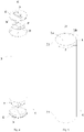
- the secondary battery 30 includes a casing 31, an electrode assembly 33 disposed within the casing 31, a top cover 32 sealingly connected with the casing 31, an electrode terminal 34 disposed on the top cover 32, and an connecting component 35.
- the casing 31 has a receiving hole 31a for receiving the electrode assembly 33 and an opening 31b that is in communication with the receiving hole 31a.
- the casing 31 has two opposite end portions 311.
- the opening 31b of the casing 31 is disposed at the end portion 311.
- the casing 31 has a cylindrical structure with one end portion open or a cylindrical structure with two end portions open. It can be understood, the casing 31 may also be in shape of square or in other shape.
- the casing 31 may be made of material such as aluminum, aluminum alloy, or the like.
- a main body of the electrode assembly 33 may be formed by winding a first electrode plate, a second electrode plate, and a separator located between the first electrode plate and the second electrode plate together, wherein the separator is an insulator sandwiched between the first electrode plate and the second electrode plate.
- the first electrode plate is exemplified as a positive electrode plate
- the second electrode plate is exemplified as a negative electrode plate.
- a positive-electrode-plate active material is coated on a coating region of the positive electrode plate
- a negative-electrode-plate active material is coated on a coating region of the negative electrode plate.
- a plurality of uncoated regions extending out from the coating regions of the main body serve as tabs.
- the electrode assembly 33 includes two tabs, i.e., a positive tab and a negative tab.
- the positive tab extends out from the coating region of the positive electrode plate, and the negative tab extends out from the coating region of the negative electrode plate.
- one tab respectively extends out from each of both ends of the main body.
- the tabs having the same polarity are connected with the electrode terminal 34 by the connecting component 35.
- the top cover 32 is used to cover the opening 31b of the casing 31.
- the top cover 32 includes an inserting portion 321 for extending into the casing 31 from the opening 31b of the casing 31.
- the inserting portion 321 of the top cover 32 is required to be inserted into the casing 31.
- the inserting portion 321 has a side wall 3211 facing an inner wall of the casing 31.
- the top cover 32 has an electrode lead-out hole (not shown in the figure).
- the electrode terminal 34 covers the electrode lead-out hole and is connected with the top cover 32.
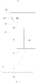
- a plurality of notches 99 are provided on an inner side of the end portion 311 of the casing 31.
- a plurality of notches 99 are provided on the side wall 3211, facing the casing 31, of the inserting portion 321 of the top cover 32.
- an inner edge of the end portion 311 of the casing 31 or an edge of the inserting portion 321 of the top cover 32 has a discontinuous toothed edge structure.
- One tooth portion is formed between two adjacent notches 99.
- the inserting portion 321 of the top cover 32 and the end portion 311 of the casing 31 are not prone to contact with each other at the notches 99, so that the region where the inserting portion 321 of the top cover 32 and the end portion 311 of the casing 31 come into contact and scratching becomes smaller.
- the size of the formed wire-like metal debris falling off from inserting portion 321 of the top cover 32 or the casing 31 can be smaller, or the possibility of producing larger-sized wire-like metal debris can be effectively reduced.
- a smaller number or smaller size of wire-like metal debris can be produced during the assembly process of the casing 31 and the top cover 32, reducing effectively the possibility of short circuit occurring at the first electrode plate and the second electrode plate of the secondary battery 30 due to overlapping with the wire-like metal debris, and improving the operational safety of the secondary battery 30.
- At least part of the side wall 3211 of the inserting portion 321 has a smooth curved surface or an inclined surface inclined toward a center of the opening 31b, so that the sharpness of the at least part of the side wall 3211 of the inserting portion 321 can be reduced, decreasing beneficially the scratching stress of the side wall 3211 of the inserting portion 321 to the inner wall of the casing 31, and reducing the possibility of producing wire-like metal debris due to scratch resulting from contact between the inserting portion 321 and the casing 31.
- the notches 99 are in identical shape, so that the convenience of processing the notches 99 and the consistency of the processing procedures can be beneficially improved, and the difficulty in processing and manufacturing the top cover 32 or the casing 31 can be reduced.
- the notches 99 are evenly arranged on the inserting portion 321 or the end portion 311 of the casing 31 along a circumferential direction Y of the opening 31b.
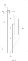
- the secondary battery 30 further includes an insulating member 36.
- the insulating member 36 is installed on the top cover 32 to isolate the top cover 32 from the electrode assembly 33.
- One end of the insulating member 36 away from the top cover 32 is pressed against the electrode assembly 33, so as to limit the position of the electrode assembly 33 and reduce the play of the electrode assembly 33 in the casing 31 along the axial direction X of the opening 31b of the casing 31.
- An axial direction X of the opening 31b is the same as an axial direction of the receiving hole 31a.
- the insulating member 36 is made of an insulating material such as rubber, plastic, or the like.
- a maximum distance between adjacent notches 99 determines a maximum size of the wire-like metal debris.
- the maximum distance between the adjacent notches 99 may be the maximum size measured along the circumferential direction Y of the opening 31b.
- a minimum thickness of the insulating member 36 protruding out from the top cover 32 along the axial direction X of the opening 31b is greater than the maximum distance between the adjacent notches 99, so that the minimum thickness of the insulating member 36 protruding out from the top cover 32 along the axial direction X of the opening 31b is greater than the maximum size of the wire-like metal debris that can be produced between the top cover 32 and the casing 31; thereby the wire-like metal debris is not prone to go in between the insulating member 36 and the electrode assembly 33, and therefore, the possibility of short circuit occurring at the first electrode plate and the second electrode plate can be reduced which is caused by the overlapping of the wire-like metal debris with the first electrode plate and the second electrode plate of the electrode assembly 33.
- the maximum thickness of the inserting portion 321 along the axial direction X of the opening 31b determines the maximum size of the wire-like metal debris along the axial direction X of the opening 31b.
- the minimum thickness of the insulating member 36 protruding out from the top cover 32 along the axial direction X of the opening 31b is greater than the maximum thickness of the inserting portion 321 of the top cover 32 along the axial direction X of the opening 31b, so that the minimum thickness of the insulating member 36 protruding out from the top cover 32 along the axial direction X of the opening 31b is greater than the maximum size of the wire-like metal debris that can be produced between the top cover 32 and the casing 31 along the axial direction X of the opening 31b; thereby, the wire-like metal debris is not prone to enter between the insulating member 36 and the electrode assembly 33, and therefore, the possibility of short circuit occurring at the first electrode plate and the second electrode plate can be reduced which is caused by the overlapping of the wire-like metal debris with the first
- the minimum thickness of the insulating member 36 protruding out from the top cover 32 along the axial direction X of the opening 31b is greater than the maximum distance between the adjacent notches 99, and the minimum thickness of the insulating member 36 protruding out from the top cover 32 along the axial direction X of the opening 31b is greater than the maximum thickness of the inserting portion 321 of the top cover 32 along the axial direction X of the opening 31b.
- the insulating member 36 includes a ring portion 361 disposed around an edge of the inserting portion 321.
- the secondary battery 30 includes an insulating sheet 37 for wrapping the electrode assembly 33.
- the insulating sheet 37 is wound along the circumferential direction Y of the opening 31b to form a cylindrical structure.
- the insulating sheet 37 extends to a position between the ring portion 361 and the casing 31.
- a part of the insulating sheet 37 located between the ring portion 361 and the casing 31 can protect from the wire-like metal debris, preventing beneficially the wire-like metal debris from entering between the insulating member 36 and the electrode assembly 33, and further reducing the possibility of short circuit occurring at the electrode assembly 33 resulting from the wire-like metal debris entering between the insulating member 36 and the electrode assembly 33.
- the top cover 32 further includes a disc portion 322.
- the inserting portion 321 protrudes from an end surface of the disc portion 322 facing the electrode assembly 33.
- a diameter of the disc portion 322 is greater than a diameter of the inserting portion 321.
- An outer edge of the disc portion 322 extends out from the inserting portion 321, to connect and fix with the end portion 311 of the casing 31.
- the disc portion 322 of the top cover 32 is sealingly connected with the end portion 311 of the casing 31.
- the disc portion 322 of the top cover 32 and the end portion 311 of the casing 31 are connected and fixed by welding.
- the welding may be laser welding or hot melt welding.
- the notches 99 are disposed on the inserting portion 321 of the top cover 32.
- the inserting portion 321 has an annular surface 3212 connected with the disc portion 322.
- the notches 99 are disposed on a side of the annular surface 3212 away from the disc portion 322.
- the end portion 311 of the casing 31 has an end surface 311a corresponding to the annular surface 3212 of the inserting portion 321 in terms of position.
- the radial direction of the opening 31b is perpendicular to the axial direction X of the opening 31b.
- an orthographic projection of the end surface 311a of the end portion 311 is located within an orthographic projection of the annular surface 3212.
- a part of the inserting portion 321 corresponding to the annular surface 3212 can block the laser light, reducing beneficially the possibility of structural damage to the electrode assembly 33 or other structural members resulting from the laser light emitting into the casing 31 or irradiating the electrode assembly 33 or other structural members.
- the notches 99 are disposed on the inner side of the end portion 311.
- a size of the notch 99 along the axial direction X of the opening 31b is smaller than a thickness of the inserting portion 321 inserted into the opening 31b.
- the inserting portion 321 can cover the entire notch 99, so that the metal slag produced when the disc portion 322 of the top cover 32 and the end portion 311 of the casing 31 are welded and connected is not prone to fall into the casing 31 from the notch 99, reducing beneficially the possibility of short circuit occurring at the first electrode plate and the second electrode plate resulting from the metal slag piercing the separator of the electrode assembly 33.
- the secondary battery 30 includes the casing 31 and the top cover 32 connected and fixed with the casing 31.
- the plurality of notches 99 are provided on the inner side of the end portion 311 of the casing 31 or the side wall 3211, facing the casing 31, of the inserting portion 321 of the top cover 32.
- the notches 99 are disposed on the inner side of the end portion 311 of the casing 31 or the side wall 3211, facing the casing 31, of the inserting portion 321 of the top cover 32, the region where the top cover 32 and the casing 31 are in contact with each other becomes smaller during the assembly process, so that the region where the inserting portion 321 and the casing 31 come into scratching becomes smaller; therefore, a smaller number or smaller size of wire-like metal debris can be produced during the assembly process of the casing 31 and the top cover 32, effectively reducing the possibility of short circuit occurring between the first electrode plate and the second pole of the secondary battery 30 due to the overlapping with the wire-like metal debris, and improving the operational safety of the secondary battery 30.
Landscapes
- Chemical & Material Sciences (AREA)
- Chemical Kinetics & Catalysis (AREA)
- Electrochemistry (AREA)
- General Chemical & Material Sciences (AREA)
- Sealing Battery Cases Or Jackets (AREA)
- Connection Of Batteries Or Terminals (AREA)
- Battery Mounting, Suspending (AREA)
Applications Claiming Priority (2)
| Application Number | Priority Date | Filing Date | Title |
|---|---|---|---|
| CN202020916363.0U CN212161863U (zh) | 2020-05-27 | 2020-05-27 | 二次电池、电池模块以及使用二次电池作为电源的装置 |
| PCT/CN2020/108249 WO2021237944A1 (zh) | 2020-05-27 | 2020-08-10 | 二次电池、电池模块以及使用二次电池作为电源的装置 |
Publications (3)
| Publication Number | Publication Date |
|---|---|
| EP3944403A4 EP3944403A4 (en) | 2022-01-26 |
| EP3944403A1 EP3944403A1 (en) | 2022-01-26 |
| EP3944403B1 true EP3944403B1 (en) | 2022-11-02 |
Family
ID=78704929
Family Applications (1)
| Application Number | Title | Priority Date | Filing Date |
|---|---|---|---|
| EP20820033.7A Active EP3944403B1 (en) | 2020-05-27 | 2020-08-10 | Secondary battery, battery module, and device using secondary battery as power source |
Country Status (5)
| Country | Link |
|---|---|
| US (2) | US11424500B2 (pl) |
| EP (1) | EP3944403B1 (pl) |
| JP (2) | JP7466654B2 (pl) |
| AU (1) | AU2020450107B2 (pl) |
| PL (1) | PL3944403T3 (pl) |
Families Citing this family (3)
| Publication number | Priority date | Publication date | Assignee | Title |
|---|---|---|---|---|
| AU2020450107B2 (en) * | 2020-05-27 | 2023-11-09 | Contemporary Amperex Technology (Hong Kong) Limited | Secondary battery, battery module, and device using secondary battery as power source |
| CN115036648B (zh) * | 2022-08-15 | 2022-11-22 | 江苏时代新能源科技有限公司 | 电极组件、电池单体、电池及用电装置 |
| KR20250151717A (ko) * | 2024-04-15 | 2025-10-22 | 삼성에스디아이 주식회사 | 이차 전지 |
Family Cites Families (20)
| Publication number | Priority date | Publication date | Assignee | Title |
|---|---|---|---|---|
| CN2416613Y (zh) | 1999-06-08 | 2001-01-24 | 深圳粤宝电子工业总公司 | 高可靠性封口结构的电池 |
| JP3608994B2 (ja) | 1999-12-24 | 2005-01-12 | Necトーキン栃木株式会社 | 密閉型電池 |
| JP4968423B2 (ja) | 2005-05-30 | 2012-07-04 | 大日本印刷株式会社 | リチウム電池の外装体 |
| JP4803023B2 (ja) | 2006-12-26 | 2011-10-26 | トヨタ自動車株式会社 | 電池及び電池の製造方法、並びに電池を搭載した車両 |
| CN201017917Y (zh) * | 2007-02-24 | 2008-02-06 | 李泰� | 一种大容量电池的外壳 |
| KR100976452B1 (ko) * | 2008-01-23 | 2010-08-17 | 삼성에스디아이 주식회사 | 이차 전지 |
| US9263713B2 (en) * | 2010-05-26 | 2016-02-16 | Samsung Sdi Co., Ltd. | Battery pack |
| US9299962B2 (en) * | 2012-05-11 | 2016-03-29 | Medtronic, Inc. | Battery encasement |
| JP2015032513A (ja) | 2013-08-05 | 2015-02-16 | 株式会社Gsユアサ | 蓄電素子及び蓄電素子の製造方法 |
| JP6171720B2 (ja) * | 2013-08-22 | 2017-08-02 | 株式会社豊田自動織機 | 蓄電装置及び蓄電装置の製造方法 |
| CN104218195A (zh) | 2014-09-27 | 2014-12-17 | 宁波世捷新能源科技有限公司 | 一种锂离子电池安全防漏液壳体 |
| US11081723B2 (en) | 2015-09-18 | 2021-08-03 | Gs Yuasa International Ltd. | Energy storage device and energy storage device production method |
| JP6085058B1 (ja) | 2016-08-02 | 2017-02-22 | 冨士発條株式会社 | 電池缶及び電池 |
| CN110326133A (zh) * | 2017-02-27 | 2019-10-11 | 三洋电机株式会社 | 方形二次电池以及其制造方法 |
| CA2997725C (en) | 2017-03-10 | 2021-08-03 | Evolution Engineering Inc. | Battery coil engaging members for downhole tools |
| CN110176558B (zh) | 2019-04-09 | 2024-04-19 | 宁德时代新能源科技股份有限公司 | 二次电池顶盖组件及二次电池 |
| CN210092146U (zh) | 2019-06-26 | 2020-02-18 | 深圳市力亚王电池有限公司 | 一种电池密封圈 |
| CN210516782U (zh) | 2019-09-19 | 2020-05-12 | 南京夏华电子有限公司 | 一种铅蓄电池用电池壳 |
| CN110729421B (zh) | 2019-11-19 | 2024-06-18 | 湖南领湃达志科技股份有限公司 | 电池盖板组件、电池电芯及其组装方法以及连接片 |
| AU2020450107B2 (en) * | 2020-05-27 | 2023-11-09 | Contemporary Amperex Technology (Hong Kong) Limited | Secondary battery, battery module, and device using secondary battery as power source |
-
2020
- 2020-08-10 AU AU2020450107A patent/AU2020450107B2/en active Active
- 2020-08-10 JP JP2022541791A patent/JP7466654B2/ja active Active
- 2020-08-10 EP EP20820033.7A patent/EP3944403B1/en active Active
- 2020-08-10 PL PL20820033.7T patent/PL3944403T3/pl unknown
- 2020-12-14 US US17/120,593 patent/US11424500B2/en active Active
-
2022
- 2022-07-14 US US17/864,453 patent/US20220344751A1/en active Pending
-
2024
- 2024-04-02 JP JP2024059652A patent/JP2024095732A/ja active Pending
Also Published As
| Publication number | Publication date |
|---|---|
| AU2020450107A1 (en) | 2022-07-14 |
| US20220344751A1 (en) | 2022-10-27 |
| US11424500B2 (en) | 2022-08-23 |
| EP3944403A4 (en) | 2022-01-26 |
| PL3944403T3 (pl) | 2023-01-02 |
| US20210376303A1 (en) | 2021-12-02 |
| JP7466654B2 (ja) | 2024-04-12 |
| BR112022014735A2 (pt) | 2022-12-06 |
| JP2024095732A (ja) | 2024-07-10 |
| JP2023509716A (ja) | 2023-03-09 |
| AU2020450107B2 (en) | 2023-11-09 |
| EP3944403A1 (en) | 2022-01-26 |
Similar Documents
| Publication | Publication Date | Title |
|---|---|---|
| KR102885441B1 (ko) | 원통형 전지 셀, 전지, 전력 소비 장치, 제조 방법 및 제조 시스템 | |
| US20220344751A1 (en) | Secondary battery, battery module, and device using secondary battery as power source | |
| EP3836297B1 (en) | Secondary battery, battery module, battery pack, device and manufacturing method | |
| KR102870559B1 (ko) | 전지 셀, 전지, 전기 장치, 전지 셀의 제조 방법 및 시스템 | |
| US12294120B2 (en) | Top cap assembly, secondary battery, battery module and device | |
| KR102737226B1 (ko) | 전지 셀, 전지, 전기 장치, 전지 셀의 제조 방법 및 시스템 | |
| EP3934020B1 (en) | Secondary battery, battery module and device | |
| CN212161863U (zh) | 二次电池、电池模块以及使用二次电池作为电源的装置 | |
| EP3926741B1 (en) | End cover assembly, battery cell, battery module and device | |
| US11929510B2 (en) | Secondary battery and manufacturing method thereof, battery module, and apparatus | |
| US20250079574A1 (en) | Shell, battery cell, battery, and electrical device | |
| US11715867B2 (en) | End cover assembly, battery cell, battery module and device | |
| KR20250082666A (ko) | 배터리 셀 및 이를 포함하는 배터리 모듈 | |
| CN120709674A (zh) | 一种单体电池、电池组及电子装置 | |
| BR112022014735B1 (pt) | Bateria secundária, módulo de bateria e dispositivo que usa uma bateria secundária como uma fonte de energia |
Legal Events
| Date | Code | Title | Description |
|---|---|---|---|
| STAA | Information on the status of an ep patent application or granted ep patent |
Free format text: STATUS: UNKNOWN |
|
| STAA | Information on the status of an ep patent application or granted ep patent |
Free format text: STATUS: THE INTERNATIONAL PUBLICATION HAS BEEN MADE |
|
| PUAI | Public reference made under article 153(3) epc to a published international application that has entered the european phase |
Free format text: ORIGINAL CODE: 0009012 |
|
| STAA | Information on the status of an ep patent application or granted ep patent |
Free format text: STATUS: REQUEST FOR EXAMINATION WAS MADE |
|
| 17P | Request for examination filed |
Effective date: 20201215 |
|
| A4 | Supplementary search report drawn up and despatched |
Effective date: 20211020 |
|
| AK | Designated contracting states |
Kind code of ref document: A1 Designated state(s): AL AT BE BG CH CY CZ DE DK EE ES FI FR GB GR HR HU IE IS IT LI LT LU LV MC MK MT NL NO PL PT RO RS SE SI SK SM TR |
|
| STAA | Information on the status of an ep patent application or granted ep patent |
Free format text: STATUS: EXAMINATION IS IN PROGRESS |
|
| 17Q | First examination report despatched |
Effective date: 20220407 |
|
| GRAP | Despatch of communication of intention to grant a patent |
Free format text: ORIGINAL CODE: EPIDOSNIGR1 |
|
| STAA | Information on the status of an ep patent application or granted ep patent |
Free format text: STATUS: GRANT OF PATENT IS INTENDED |
|
| INTG | Intention to grant announced |
Effective date: 20220728 |
|
| GRAS | Grant fee paid |
Free format text: ORIGINAL CODE: EPIDOSNIGR3 |
|
| GRAA | (expected) grant |
Free format text: ORIGINAL CODE: 0009210 |
|
| STAA | Information on the status of an ep patent application or granted ep patent |
Free format text: STATUS: THE PATENT HAS BEEN GRANTED |
|
| AK | Designated contracting states |
Kind code of ref document: B1 Designated state(s): AL AT BE BG CH CY CZ DE DK EE ES FI FR GB GR HR HU IE IS IT LI LT LU LV MC MK MT NL NO PL PT RO RS SE SI SK SM TR |
|
| DAV | Request for validation of the european patent (deleted) | ||
| DAX | Request for extension of the european patent (deleted) | ||
| REG | Reference to a national code |
Ref country code: GB Ref legal event code: FG4D |
|
| REG | Reference to a national code |
Ref country code: CH Ref legal event code: EP Ref country code: AT Ref legal event code: REF Ref document number: 1529431 Country of ref document: AT Kind code of ref document: T Effective date: 20221115 |
|
| REG | Reference to a national code |
Ref country code: DE Ref legal event code: R096 Ref document number: 602020006087 Country of ref document: DE |
|
| REG | Reference to a national code |
Ref country code: SE Ref legal event code: TRGR |
|
| REG | Reference to a national code |
Ref country code: NL Ref legal event code: FP Ref country code: IE Ref legal event code: FG4D |
|
| REG | Reference to a national code |
Ref country code: LT Ref legal event code: MG9D |
|
| PG25 | Lapsed in a contracting state [announced via postgrant information from national office to epo] |
Ref country code: PT Free format text: LAPSE BECAUSE OF FAILURE TO SUBMIT A TRANSLATION OF THE DESCRIPTION OR TO PAY THE FEE WITHIN THE PRESCRIBED TIME-LIMIT Effective date: 20230302 Ref country code: NO Free format text: LAPSE BECAUSE OF FAILURE TO SUBMIT A TRANSLATION OF THE DESCRIPTION OR TO PAY THE FEE WITHIN THE PRESCRIBED TIME-LIMIT Effective date: 20230202 Ref country code: LT Free format text: LAPSE BECAUSE OF FAILURE TO SUBMIT A TRANSLATION OF THE DESCRIPTION OR TO PAY THE FEE WITHIN THE PRESCRIBED TIME-LIMIT Effective date: 20221102 Ref country code: FI Free format text: LAPSE BECAUSE OF FAILURE TO SUBMIT A TRANSLATION OF THE DESCRIPTION OR TO PAY THE FEE WITHIN THE PRESCRIBED TIME-LIMIT Effective date: 20221102 Ref country code: ES Free format text: LAPSE BECAUSE OF FAILURE TO SUBMIT A TRANSLATION OF THE DESCRIPTION OR TO PAY THE FEE WITHIN THE PRESCRIBED TIME-LIMIT Effective date: 20221102 |
|
| REG | Reference to a national code |
Ref country code: HU Ref legal event code: AG4A Ref document number: E060827 Country of ref document: HU |
|
| PG25 | Lapsed in a contracting state [announced via postgrant information from national office to epo] |
Ref country code: RS Free format text: LAPSE BECAUSE OF FAILURE TO SUBMIT A TRANSLATION OF THE DESCRIPTION OR TO PAY THE FEE WITHIN THE PRESCRIBED TIME-LIMIT Effective date: 20221102 Ref country code: LV Free format text: LAPSE BECAUSE OF FAILURE TO SUBMIT A TRANSLATION OF THE DESCRIPTION OR TO PAY THE FEE WITHIN THE PRESCRIBED TIME-LIMIT Effective date: 20221102 Ref country code: IS Free format text: LAPSE BECAUSE OF FAILURE TO SUBMIT A TRANSLATION OF THE DESCRIPTION OR TO PAY THE FEE WITHIN THE PRESCRIBED TIME-LIMIT Effective date: 20230302 Ref country code: HR Free format text: LAPSE BECAUSE OF FAILURE TO SUBMIT A TRANSLATION OF THE DESCRIPTION OR TO PAY THE FEE WITHIN THE PRESCRIBED TIME-LIMIT Effective date: 20221102 Ref country code: GR Free format text: LAPSE BECAUSE OF FAILURE TO SUBMIT A TRANSLATION OF THE DESCRIPTION OR TO PAY THE FEE WITHIN THE PRESCRIBED TIME-LIMIT Effective date: 20230203 |
|
| P01 | Opt-out of the competence of the unified patent court (upc) registered |
Effective date: 20230516 |
|
| PG25 | Lapsed in a contracting state [announced via postgrant information from national office to epo] |
Ref country code: SM Free format text: LAPSE BECAUSE OF FAILURE TO SUBMIT A TRANSLATION OF THE DESCRIPTION OR TO PAY THE FEE WITHIN THE PRESCRIBED TIME-LIMIT Effective date: 20221102 Ref country code: RO Free format text: LAPSE BECAUSE OF FAILURE TO SUBMIT A TRANSLATION OF THE DESCRIPTION OR TO PAY THE FEE WITHIN THE PRESCRIBED TIME-LIMIT Effective date: 20221102 Ref country code: EE Free format text: LAPSE BECAUSE OF FAILURE TO SUBMIT A TRANSLATION OF THE DESCRIPTION OR TO PAY THE FEE WITHIN THE PRESCRIBED TIME-LIMIT Effective date: 20221102 Ref country code: DK Free format text: LAPSE BECAUSE OF FAILURE TO SUBMIT A TRANSLATION OF THE DESCRIPTION OR TO PAY THE FEE WITHIN THE PRESCRIBED TIME-LIMIT Effective date: 20221102 Ref country code: CZ Free format text: LAPSE BECAUSE OF FAILURE TO SUBMIT A TRANSLATION OF THE DESCRIPTION OR TO PAY THE FEE WITHIN THE PRESCRIBED TIME-LIMIT Effective date: 20221102 |
|
| REG | Reference to a national code |
Ref country code: DE Ref legal event code: R097 Ref document number: 602020006087 Country of ref document: DE |
|
| PG25 | Lapsed in a contracting state [announced via postgrant information from national office to epo] |
Ref country code: SK Free format text: LAPSE BECAUSE OF FAILURE TO SUBMIT A TRANSLATION OF THE DESCRIPTION OR TO PAY THE FEE WITHIN THE PRESCRIBED TIME-LIMIT Effective date: 20221102 Ref country code: AL Free format text: LAPSE BECAUSE OF FAILURE TO SUBMIT A TRANSLATION OF THE DESCRIPTION OR TO PAY THE FEE WITHIN THE PRESCRIBED TIME-LIMIT Effective date: 20221102 |
|
| PLBE | No opposition filed within time limit |
Free format text: ORIGINAL CODE: 0009261 |
|
| STAA | Information on the status of an ep patent application or granted ep patent |
Free format text: STATUS: NO OPPOSITION FILED WITHIN TIME LIMIT |
|
| 26N | No opposition filed |
Effective date: 20230803 |
|
| PG25 | Lapsed in a contracting state [announced via postgrant information from national office to epo] |
Ref country code: SI Free format text: LAPSE BECAUSE OF FAILURE TO SUBMIT A TRANSLATION OF THE DESCRIPTION OR TO PAY THE FEE WITHIN THE PRESCRIBED TIME-LIMIT Effective date: 20221102 |
|
| REG | Reference to a national code |
Ref country code: AT Ref legal event code: UEP Ref document number: 1529431 Country of ref document: AT Kind code of ref document: T Effective date: 20221102 |
|
| PG25 | Lapsed in a contracting state [announced via postgrant information from national office to epo] |
Ref country code: MC Free format text: LAPSE BECAUSE OF FAILURE TO SUBMIT A TRANSLATION OF THE DESCRIPTION OR TO PAY THE FEE WITHIN THE PRESCRIBED TIME-LIMIT Effective date: 20221102 |
|
| REG | Reference to a national code |
Ref country code: CH Ref legal event code: PL |
|
| PG25 | Lapsed in a contracting state [announced via postgrant information from national office to epo] |
Ref country code: MC Free format text: LAPSE BECAUSE OF FAILURE TO SUBMIT A TRANSLATION OF THE DESCRIPTION OR TO PAY THE FEE WITHIN THE PRESCRIBED TIME-LIMIT Effective date: 20221102 |
|
| PG25 | Lapsed in a contracting state [announced via postgrant information from national office to epo] |
Ref country code: LU Free format text: LAPSE BECAUSE OF NON-PAYMENT OF DUE FEES Effective date: 20230810 |
|
| PG25 | Lapsed in a contracting state [announced via postgrant information from national office to epo] |
Ref country code: LU Free format text: LAPSE BECAUSE OF NON-PAYMENT OF DUE FEES Effective date: 20230810 Ref country code: CH Free format text: LAPSE BECAUSE OF NON-PAYMENT OF DUE FEES Effective date: 20230831 |
|
| REG | Reference to a national code |
Ref country code: IE Ref legal event code: MM4A |
|
| PG25 | Lapsed in a contracting state [announced via postgrant information from national office to epo] |
Ref country code: IE Free format text: LAPSE BECAUSE OF NON-PAYMENT OF DUE FEES Effective date: 20230810 |
|
| PG25 | Lapsed in a contracting state [announced via postgrant information from national office to epo] |
Ref country code: IE Free format text: LAPSE BECAUSE OF NON-PAYMENT OF DUE FEES Effective date: 20230810 |
|
| REG | Reference to a national code |
Ref country code: DE Ref legal event code: R081 Ref document number: 602020006087 Country of ref document: DE Owner name: CONTEMPORARY AMPEREX TECHNOLOGY (HONG KONG) LI, HK Free format text: FORMER OWNER: CONTEMPORARY AMPEREX TECHNOLOGY CO., LIMITED, NINGDE CITY, FUJIAN, CN |
|
| REG | Reference to a national code |
Ref country code: NL Ref legal event code: PD Owner name: CONTEMPORARY AMPEREX TECHNOLOGY (HONG KONG) LIMITED; CN Free format text: DETAILS ASSIGNMENT: CHANGE OF OWNER(S), ASSIGNMENT; FORMER OWNER NAME: CONTEMPORARY AMPEREX TECHNOLOGY CO., LIMITED Effective date: 20240819 |
|
| REG | Reference to a national code |
Ref country code: GB Ref legal event code: 732E Free format text: REGISTERED BETWEEN 20240822 AND 20240828 |
|
| REG | Reference to a national code |
Ref country code: HU Ref legal event code: GB9C Owner name: CONTEMPORARY AMPEREX TECHNOLOGY (HONG KONG) LIMITED, HK Free format text: FORMER OWNER(S): CONTEMPORARY AMPEREX TECHNOLOGY CO., LIMITED, CN Ref country code: HU Ref legal event code: FH1C Free format text: FORMER REPRESENTATIVE(S): SBGK SZABADALMI UEGYVIVOEI IRODA, HU Representative=s name: DANUBIA SZABADALMI ES JOGI IRODA KFT., HU |
|
| PG25 | Lapsed in a contracting state [announced via postgrant information from national office to epo] |
Ref country code: BG Free format text: LAPSE BECAUSE OF FAILURE TO SUBMIT A TRANSLATION OF THE DESCRIPTION OR TO PAY THE FEE WITHIN THE PRESCRIBED TIME-LIMIT Effective date: 20221102 |
|
| REG | Reference to a national code |
Ref country code: AT Ref legal event code: PC Ref document number: 1529431 Country of ref document: AT Kind code of ref document: T Owner name: CONTEMPORARY AMPEREX TECHNOLOGY (HONG KONG) LI, HK Effective date: 20240923 |
|
| PG25 | Lapsed in a contracting state [announced via postgrant information from national office to epo] |
Ref country code: BG Free format text: LAPSE BECAUSE OF FAILURE TO SUBMIT A TRANSLATION OF THE DESCRIPTION OR TO PAY THE FEE WITHIN THE PRESCRIBED TIME-LIMIT Effective date: 20221102 |
|
| REG | Reference to a national code |
Ref country code: BE Ref legal event code: PD Owner name: CONTEMPORARY AMPEREX TECHNOLOGY (HONG KONG) LIMITED; CN Free format text: DETAILS ASSIGNMENT: CHANGE OF OWNER(S), ASSIGNMENT; FORMER OWNER NAME: CONTEMPORARY AMPEREX TECHNOLOGY CO., LIMITED Effective date: 20240807 |
|
| PGFP | Annual fee paid to national office [announced via postgrant information from national office to epo] |
Ref country code: SE Payment date: 20250310 Year of fee payment: 6 |
|
| PGFP | Annual fee paid to national office [announced via postgrant information from national office to epo] |
Ref country code: PL Payment date: 20250529 Year of fee payment: 6 |
|
| PGFP | Annual fee paid to national office [announced via postgrant information from national office to epo] |
Ref country code: GB Payment date: 20250619 Year of fee payment: 6 |
|
| PGFP | Annual fee paid to national office [announced via postgrant information from national office to epo] |
Ref country code: NL Payment date: 20250613 Year of fee payment: 6 |
|
| PGFP | Annual fee paid to national office [announced via postgrant information from national office to epo] |
Ref country code: FR Payment date: 20250610 Year of fee payment: 6 |
|
| PG25 | Lapsed in a contracting state [announced via postgrant information from national office to epo] |
Ref country code: CY Free format text: LAPSE BECAUSE OF FAILURE TO SUBMIT A TRANSLATION OF THE DESCRIPTION OR TO PAY THE FEE WITHIN THE PRESCRIBED TIME-LIMIT; INVALID AB INITIO Effective date: 20200810 |
|
| PGFP | Annual fee paid to national office [announced via postgrant information from national office to epo] |
Ref country code: HU Payment date: 20250711 Year of fee payment: 6 |
|
| PGFP | Annual fee paid to national office [announced via postgrant information from national office to epo] |
Ref country code: DE Payment date: 20250618 Year of fee payment: 6 |
|
| PGFP | Annual fee paid to national office [announced via postgrant information from national office to epo] |
Ref country code: IT Payment date: 20250722 Year of fee payment: 6 |
|
| PGFP | Annual fee paid to national office [announced via postgrant information from national office to epo] |
Ref country code: BE Payment date: 20250703 Year of fee payment: 6 |
|
| PGFP | Annual fee paid to national office [announced via postgrant information from national office to epo] |
Ref country code: AT Payment date: 20250725 Year of fee payment: 6 |
|
| PG25 | Lapsed in a contracting state [announced via postgrant information from national office to epo] |
Ref country code: TR Free format text: LAPSE BECAUSE OF FAILURE TO SUBMIT A TRANSLATION OF THE DESCRIPTION OR TO PAY THE FEE WITHIN THE PRESCRIBED TIME-LIMIT Effective date: 20221102 |